Installation 1 3 2 4 5 7 Operation 6 Troubleshooting - Home Depot
Installation 1 3 2 4 5 7 Operation 6 Troubleshooting - Home Depot
Installation 1 3 2 4 5 7 Operation 6 Troubleshooting - Home Depot

You also want an ePaper? Increase the reach of your titles
YUMPU automatically turns print PDFs into web optimized ePapers that Google loves.
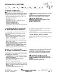
English<br />
For Halogen/Incandescent Lighting use<br />
a Halogen/Incandescent Dimmer.<br />
MA-600, MA-600M, MA-600G, MSC-600, MSC-600M, MSC-600MG<br />
120 V 60 Hz 600 W<br />
MA-1000, MSC-1000, MSC-1000M<br />
120 V 60 Hz 1000 W<br />
For Magnetic Low-Voltage Lighting use a Magnetic<br />
Low-Voltage Dimmer ONLY.<br />
MALV-600, MSCLV-600, MSCLV-600M 120 V 60 Hz 600 VA / 450 W<br />
MALV-1000, MSCLV-1000, MSCLV-1000M 120 V 60 Hz 1000 VA / 800 W<br />
Companion Dimmer<br />
MA-R, MSC-AD 120 V 60 Hz 8.3 A<br />
For Electronic Low-Voltage Lighting use an Electronic<br />
Low-Voltage Dimmer ONLY. Purchase Separately.<br />
Important Notes<br />
Please read before installing.<br />
1. Caution: When installing Halogen/Incandescent Dimmers—To reduce the risk of overheating<br />
and possible damage to other equipment, DO NOT use to control receptacles, motor-operated<br />
appliances, fluorescent lighting fixtures, electronic low-voltage or magnetic low-voltage fixtures or<br />
transformer-supplied appliances.<br />
Caution: When installing Magnetic Low-voltage Dimmers—To reduce the risk of overheating<br />
and possible damage to other equipment, DO NOT use to control receptacles, electronic lowvoltage<br />
fixtures or motor-operated appliances.<br />
2. Caution: Operating a dimmed magnetic low-voltage circuit with all lamps inoperative or<br />
removed may result in current flow in excess of normal levels. To avoid possible transformer<br />
overheating or failure, Lutron strongly recommends the following:<br />
• DO NOT operate without operative lamps in place.<br />
• Replace burned out lamps as soon as possible.<br />
• To prevent premature failure due to overcurrent, use transformers with thermal protection<br />
or fused primary transformer windings.<br />
3. Install in accordance with all national and local electrical codes.<br />
4. DO NOT use Maestro® dimmers for compact Fluorescent (Energy Saver) lamps.<br />
5. When no “grounding means” exist within the wallbox then the NEC® 2008, Article 404.9<br />
allows a dimmer without a grounding connection to be installed as a replacement, as long<br />
as a plastic, noncombustible wallplate is used. For this type of installation, cap or remove<br />
the green ground wire on the dimmer and use an appropriate wallplate such as Claro® or<br />
Satin Colors® series wallplates by Lutron.<br />
6. Do not paint Dimmers or Maestro Companion Dimmers (MA-R, MSC-AD).<br />
7. Maestro Dimmers are not compatible with standard 3-way/4-way switches, for use only with<br />
Maestro Companion Dimmers (MA-R, MSC-AD).<br />
8. Maestro Companion Dimmers (MA-R, MSC-AD) can not be used individually and must be<br />
used in conjunction with a Maestro Dimmer in a 3-way/4-way application.<br />
9. In any 3-way/4-way circuit use only one Dimmer with up to 9 Maestro Companion Dimmers<br />
(MA-R, MSC-AD).<br />
10. Do not use where total lamp wattage is less than 40 W / VA or greater than wattage indicated<br />
on unit label.<br />
11. Operate between 32 °F (0 °C) and 104 °F (40 °C).<br />
12. Smart Dimmers may feel warm to the touch during normal operation.<br />
13. Recommended wallbox depth is 2.5 in (64 mm) minimum.<br />
14. Maximum wire length between the Dimmer and the last Maestro Companion Dimmer<br />
(MA-R, MSC-AD) is 250 feet (76 m).<br />
15. Clean dimmers with a soft damp cloth only. Do not use any chemical cleaners.<br />
16. DO NOT use Halogen/Incandescent or Electronic Low-Voltage dimmers for Magnetic<br />
Low-Voltage lighting.<br />
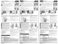
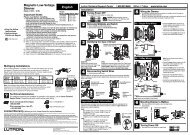
Multigang <strong>Installation</strong>s<br />
When installing more than one control in the same wallbox, it may be necessary to remove all<br />
inner side sections prior to wiring (see below). Using pliers, bend side sections up and down until<br />
they break off. Repeat for each side section to be removed. Removal of Dimmer side sections<br />
reduces maximum load capacity. Refer to chart below for maximum Dimmer capacity.<br />
Breaking Side Sections<br />
Derating Chart<br />
Dimmer Rating<br />
Halogen/Incandescent<br />
600 W<br />
1000 W<br />
Magnetic Low-Voltage<br />
600 VA/450 W*<br />
1000 VA/800 W*<br />
Maximum Load<br />
No Sides<br />
Removed<br />
600 W<br />
1000 W<br />
600 VA/450 W*<br />
1000 VA/800 W*<br />
Technical Assistance<br />
If you have questions concerning the installation or operation of this product, call the<br />
Lutron Technical Support Center. Please provide exact model number when calling.<br />
U.S.A. and Canada (24 hrs/7days)<br />
1.800.523.9466<br />
México<br />
+1.888.235.2910<br />
Other countries 8am – 8pm ET<br />
+1.610.282.3800<br />
Each control has inside<br />
section removed.<br />
1 Side<br />
Removed<br />
500 W<br />
800 W<br />
500 VA/400 W*<br />
800 VA/650 W*<br />
Do not remove<br />
outside sections.<br />
Middle control has two<br />
side sections removed.<br />
2 Sides<br />
Removed<br />
400 W<br />
650 W<br />
400 VA/300 W*<br />
650 VA/500 W*<br />
* The maximum lamp wattage is determined by the efficiency of the transformer, with 70%–85% as<br />
typical. For actual transformer efficiency, contact either the fixture or transformer manufacturer.<br />
The total VA rating of the transformer(s) shall not exceed the VA rating of the dimmer.<br />
Fax +1.610.282.6311<br />
http://www.lutron.com<br />
Limited Warranty<br />
(Valid only in U.S.A., Canada, Puerto Rico, and the Caribbean.)<br />
Lutron will, at its option, repair or replace any unit that is defective in materials or manufacture within one year after purchase.<br />
For warranty service, return unit to place of purchase or mail to Lutron at 7200 Suter Rd., Coopersburg, PA 18036-1299,<br />
postage pre-paid.<br />
THIS WARRANTY IS IN LIEU OF ALL OTHER EXPRESS WARRANTIES, AND THE IMPLIED WARRANTY OF MERCHANTABILITY<br />
IS LIMITED TO ONE YEAR FROM PURCHASE. THIS WARRANTY DOES NOT COVER THE COST OF INSTALLATION, REMOVAL<br />
OR REINSTALLATION, OR DAMAGE RESULTING FROM MISUSE, ABUSE, OR DAMAGE FROM IMPROPER WIRING OR INSTAL-<br />
LATION. THIS WARRANTY DOES NOT COVER INCIDENTAL OR CONSEQUENTIAL DAMAGES. LUTRON’S LIABILITY ON ANY<br />
CLAIM FOR DAMAGES ARISING OUT OF OR IN CONNECTION WITH THE MANUFACTURE, SALE, INSTALLATION, DELIVERY,<br />
OR USE OF THE UNIT SHALL NEVER EXCEED THE PURCHASE PRICE OF THE UNIT.<br />
This warranty gives you specific legal rights, and you may have other rights which vary from state to state. Some states do not<br />
allow the exclusion or limitation of incidental or consequential damages, or limitation on how long an implied warranty may last,<br />
so the above limitations may not apply to you.<br />
This product is covered under one or more of the following U.S. patents: 5,248,919; 5,399,940; 5,637,930; 5,798,581;<br />
6,169,377; 7,190,125; 7,365,282; 7,546,473 and corresponding foreign patents. U.S. and foreign patents pending. Lutron,<br />
Claro, Satin Colors, and Maestro are registered trademarks and FASS is a trademark of Lutron Electronics Co., Inc. NEC is a<br />
registered trademark of National Fire Protection Association, Quincy, Massachusetts.<br />
© 2009 Lutron Electronics Co., Inc.<br />
Lutron Electronics Co., Inc.<br />
7200 Suter Road<br />
Coopersburg, PA 18036-1299, U.S.A.<br />
Made and printed in the U.S.A. 9/09 P/N 030-1122 Rev. A<br />
Lutron Technical Support Center 1.800.523.9466 24 hrs / 7 days www.lutron.com<br />
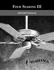
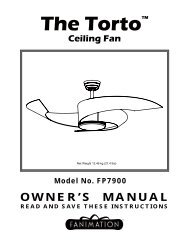
<strong>Installation</strong><br />
1<br />
2<br />
3<br />
4<br />
Removing wallplates and switches.<br />
• Remove the wallplate and switch mounting screws.<br />
• Carefully remove switch from wall (do not remove wires).<br />
3/8 in<br />
(10 mm)<br />
Identifying the circuit type.<br />
Ground<br />
(Bare Copper or<br />
Green Wire)<br />
Ground<br />
(Bare Copper or<br />
Green Wire)<br />
Different colored<br />
screw (Common)<br />
Note: Screw<br />
placement may<br />
be different on<br />
your switch.<br />
Same<br />
colored screw<br />
(or marked IN<br />
or OUT)<br />
Turning OFF power.<br />
• Turn power OFF at circuit breaker (or remove fuse).<br />
3a - Single-Location control<br />
3b - Two-Location control<br />
3c - Three-Location control<br />
Ground<br />
(Bare Copper or<br />
Green Wire)<br />
Tagged wire<br />
Tagged wires<br />
Disconnecting switch wires.<br />
One switch controlling a light fixture.<br />
This switch will be a single-pole. The switch will<br />
have insulated wires connected to two screws of<br />
the same color plus a green ground screw.<br />
See step 5a when wiring.<br />
Two switches controlling a light fixture.<br />
Both switches will be 3-way. Each switch will<br />
have insulated wires connected to three screws<br />
plus a green ground screw. One of these wires is<br />
connected to a screw of a different color (not<br />
green) or labeled COMMON. TAG this wire on<br />
both switches to identify when wiring.<br />
See step 5b when wiring.<br />
Three switches controlling a light fixture.<br />
Two switches will be 3-way and one will be a 4-<br />
way. TAG the two 3-way switches as in the Two-<br />
Location diagram above. The 4-way switch will<br />
have insulated wires connected to four screws<br />
plus a green ground screw. TAG the two same<br />
color insulated wires which are connected to<br />
opposite colored screws.<br />
Important Note: Your wall switch may have two wires attached to the same screw (see illustrations<br />
below for examples). Tape these two wires together before disconnecting. When wiring,<br />
connect wires to the Dimmer the same way they were connected to the switch.<br />
Screw<br />
Terminals:<br />
Turn screws to<br />
loosen.<br />
One wire in the<br />
backwired hole<br />
and one to the<br />
screw.<br />
Push-in<br />
Terminals:<br />
Insert screwdriver.<br />
Pull<br />
wire out.<br />
Important Wiring Information<br />
One continuous<br />
wire to the<br />
screw.<br />
Looped Wire:<br />
Turn screw to<br />
loosen.<br />
When making wire connections, follow the recommended strip lengths and combinations for the<br />
supplied wire connector. Note: All wire connectors provided are suitable for copper wire only.<br />
For aluminum wire, consult an electrician.<br />
Wire Connector:<br />
Use to join one 14 AWG (1.5 mm 2 ) or<br />
12 AWG (2.5 mm 2 ) ground wire with<br />
one 18 AWG (0.75 mm 2 ) dimmer<br />
ground wire.<br />
Twist wire<br />
connector tight.<br />
WARNING: Shock Hazard. May result in serious<br />
injury or death. Turn off power at circuit<br />
breaker before installing the unit.<br />
Trim or strip wallbox wires to the length indicated by the strip gauge on<br />
the back of the dimmer<br />
Push-in Terminals: Insert wires fully.<br />
Note: Push-in terminals are for use with<br />
14 AWG (1.5 mm 2 ) solid copper wire only.<br />
DO NOT use stranded or twisted wire.<br />
OR<br />
Screw Terminals: Tighten securely.<br />
Screw terminals are for use with 12 AWG<br />
(2.5 mm 2 ) or 14 AWG (1.5 mm 2 ) solid copper<br />
wire only. DO NOT use stranded or twisted<br />
wire.<br />
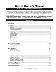
5<br />
Wiring.<br />
• For installations involving more than one control in a wallbox, refer to Multigang<br />
<strong>Installation</strong>s before beginning.<br />
• Use the screw or push-in terminals when making connections on the Dimmer or<br />
Companion Dimmer.<br />
• Wire all controls before mounting.<br />
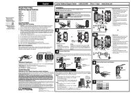
5a - Single-Location control<br />
Brass screw<br />
Black screw<br />
Green wire<br />
Live<br />
120 V~<br />
60 Hz<br />
Dimmer<br />
Reference Wiring Diagram<br />
Brass<br />
Black<br />
Wallbox<br />
Dimmer<br />
Green<br />
Ground<br />
Blue<br />
Ground<br />
5b - Two-Location control<br />
Light<br />
Fixture<br />
Neutral<br />
5c - Three-Location control or more<br />
Wiring the Dimmer:<br />
• Connect the green ground wire on the Dimmer to<br />
the bare copper or green ground wire in the wallbox.<br />
• Connect either of the wires removed from the<br />
switch to the black screw terminal on the<br />
Dimmer.<br />
• Connect the remaining wire removed from the<br />
switch to the brass screw terminal on the<br />
Dimmer.<br />
• Tighten the blue screw terminal on the Dimmer. It<br />
is not used in a single-pole circuit.<br />
One location will be replaced with a Dimmer and the other with a Companion Dimmer.<br />
Brass screw<br />
Black screw<br />
Brass screw<br />
Black screw<br />
Dimmer<br />
Green wire<br />
Companion<br />
Dimmer<br />
Green wire<br />
Blue screw<br />
Tag<br />
Blue screw<br />
Tag<br />
Reference Wiring Diagram<br />
Live<br />
120 V~<br />
60 Hz<br />
Dimmer or<br />
Companion Dimmer<br />
Brass<br />
Black<br />
Wallbox<br />
Green<br />
Ground<br />
Blue<br />
Ground<br />
Ground<br />
Dimmer or<br />
Companion Dimmer<br />
Brass<br />
Black<br />
Green<br />
Wallbox<br />
Wiring the Dimmer:<br />
• Connect the green ground wire on the Dimmer to<br />
the bare copper or green ground wire in the<br />
wallbox. (See important note 5.)<br />
• Connect the tagged wire removed from the switch<br />
to the black screw terminal on the Dimmer.<br />
• Connect one of the remaining wires removed from<br />
the switch to the brass screw terminal on the<br />
Dimmer.<br />
• Connect the remaining wire removed from the<br />
switch (note wire color) to the blue screw terminal<br />
on the Dimmer.<br />
Wiring the Companion Dimmer (MA-R, MSC-AD):<br />
• Connect the green ground wire on the Companion<br />
Dimmer to the bare copper or green ground wire<br />
in the wallbox. (See important note 5.)<br />
• Connect the tagged wire removed from the switch<br />
to the black screw terminal on the Companion<br />
Dimmer.<br />
• Connect the same color wire connected to the blue<br />
screw terminal on the Dimmer (wire color noted<br />
above) to the blue screw terminal on the<br />
Companion Dimmer.<br />
• Connect the remaining wire removed from the<br />
switch to the brass screw terminal on the<br />
Companion Dimmer.<br />
Ground<br />
Blue<br />
Light<br />
Fixture<br />
Neutral<br />
One location will be replaced with a Dimmer and the others with Companion Dimmers.<br />
Only one Dimmer can be used with up to 9 Companion Dimmers.<br />
Brass screw<br />
Dimmer or<br />
Companion<br />
Dimmer<br />
Black screw<br />
Brass screw<br />
Green wire<br />
Dimmer or<br />
Companion<br />
Dimmer<br />
Black screw<br />
Green wire<br />
Blue<br />
screw<br />
Blue screw<br />
Tag<br />
Tagged wires<br />
Reference Wiring Diagram<br />
Live<br />
120 V~<br />
60 Hz<br />
Dimmer or<br />
Companion Dimmer<br />
Brass<br />
Black<br />
Wallbox<br />
Green<br />
Ground<br />
Blue<br />
Ground<br />
Ground<br />
Dimmer or<br />
Companion Dimmer<br />
Brass<br />
Black<br />
Green<br />
Wallbox<br />
Ground<br />
Replace the 4-way switch(es)<br />
Note: 4-way switches may be replaced with either a<br />
Dimmer or a Companion Dimmer.<br />
• Connect the green ground wire on the Dimmer or<br />
Companion Dimmer to the bare copper or green<br />
ground wire in the wallbox. (See important note 5.)<br />
• Connect both of the tagged wires (noting their<br />
color) removed from the 4-way switch to the blue<br />
screw terminal on the Dimmer or Companion<br />
Dimmer (one wire to the screw and the other to<br />
the push-in terminal).<br />
• Connect one of the remaining wires removed from<br />
the switch to the black screw terminal on the<br />
Dimmer or Companion Dimmer.<br />
• Connect the remaining wire removed from the<br />
switch to the brass screw terminal on the Dimmer<br />
or Companion Dimmer.<br />
Replace the 3-way switches<br />
• Connect the green ground wire on the Dimmer or<br />
Companion Dimmer to the bare copper or green<br />
ground wire in the wallbox. (See important note 5.)<br />
• Connect the tagged wire removed from the switch<br />
to the black screw terminal on the Dimmer or<br />
Companion Dimmer.<br />
• Connect the same color wire connected to the<br />
blue screw terminal on the Dimmer or Companion<br />
Dimmer that replaced a 4-way switch (wire color<br />
noted above) to the blue screw terminal on the<br />
Dimmer or Companion Dimmer.<br />
• Connect the remaining wire removed from the<br />
switch to the brass screw terminal on the Dimmer<br />
or Companion Dimmer.<br />
Blue<br />
Dimmer or<br />
Companion Dimmer<br />
Brass<br />
Black<br />
Green<br />
Wallbox<br />
Ground<br />
Blue<br />
Light<br />
Fixture<br />
Neutral<br />
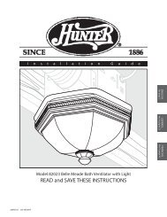
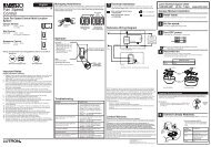
6<br />
7<br />
Mounting dimmer and companion Dimmer(s)<br />
to wallbox.<br />
• Form wires carefully into the wallbox, mount and align Dimmer<br />
(and Companion Dimmers).<br />
• Install wallplate(s).<br />
Start screws.<br />
Turning ON power.<br />
• Turn power ON at circuit breaker (or replace fuse).<br />
<strong>Operation</strong><br />
Tap Button Options<br />
• Tap once when unit is off -<br />
Lights brighten smoothly to<br />
preset intensity.<br />
• Tap once when unit is on -<br />
Lights dim smoothly to off.<br />
• Tap twice quickly -<br />
Lights brighten rapidly to<br />
full intensity.<br />
• Press and hold when unit<br />
is on - Each time dimmer is<br />
turned off delayed fade to<br />
OFF can be activated. As the<br />
tap button is held, the LEDs<br />
will begin to flash. The first<br />
flashing LED represents a<br />
10 second fade to OFF. Each<br />
additional flashing LED represents<br />
an additional<br />
10 seconds of delay before<br />
lights fade to OFF (up to<br />
60 seconds of delay).<br />
<strong>Troubleshooting</strong><br />
Note: Do not overtighten<br />
mounting screws.<br />
Permanent damage<br />
may occur.<br />
• Easy-to-follow<br />
Instructions<br />
• Instrucciones Fáciles<br />
de Seguir<br />
030-1122<br />
Dimming Rocker<br />
Press to brighten<br />
Press to dim<br />
LEDs<br />
light level indicators<br />
(not available on Companion Dimmers)<br />
FASSTM - Front<br />
Accessible Service<br />
Switch<br />
IMPORTANT NOTICE:<br />
To replace bulb, power may be<br />
conveniently removed by pulling<br />
the FASS switch out on both the<br />
Dimmer and any Companion<br />
Dimmers.<br />
For any procedure other than<br />
routine bulb replacement,<br />
power must be disconnected<br />
at the main electrical panel.<br />
To learn about the Advanced Features of Maestro Dimmers including locked preset and<br />
adjustable fade times, please visit:<br />
http://www.lutron.com/maestro/advfeatures<br />
or call the Lutron Technical Support Center. 1.800.523.9466<br />
Symptom<br />
Light does not turn On or no<br />
LEDs turn On.<br />
Light turns On and Dimmer works,<br />
but Companion Dimmer does not<br />
work.<br />
Light does not remain On, LEDs<br />
glow dimly or blink.<br />
Tap switch on Companion Dimmer<br />
does not work at brightest level.<br />
Possible Cause<br />
• Front Accessible Service Switch (FASS) on Dimmer or<br />
Companion Dimmer is pulled out to the OFF position.<br />
• Light bulb(s) burned out.<br />
• Breaker is OFF or tripped.<br />
• Wiring error. Call Lutron Technical Support Center.<br />
• Wire connected to the blue screw terminal on Dimmer<br />
is not the same wire connected to the blue screw<br />
terminal on Companion Dimmer.<br />
• Blue screw terminal miswired to neutral wire or<br />
touching ground.<br />
• Load is less that 40 W.<br />
Align dimmer and<br />
tighten screws.
Español<br />
Para Iluminación Halógeno/Incandescente, use un<br />
Atenuador Halógeno/Incandescente.<br />
MA-600, MA-600M, MA-600G, MSC-600, MSC-600M, MSC-600MG<br />
120 V 60 Hz 600 W<br />
MA-1000, MSC-1000, MSC-1000M<br />
120 V 60 Hz 1 000 W<br />
Para Iluminación Magnética de Bajo Voltaje, use un<br />
Atenuador Magnético de Bajo Voltaje SOLAMENTE.<br />
MALV-600, MSCLV-600, MSCLV-600M 120 V 60 Hz 600 VA / 450 W<br />
MALV-1000, MSCLV-1000, MSCLV-1000M 120 V 60 Hz 1 000 VA / 800 W<br />
Atenuador Accesorio<br />
MA-R, MSC-AD 120 V 60 Hz 8,3 A<br />
Para Iluminación Electrónica de Bajo Voltaje,<br />
use un Atenuador Electrónico de Bajo Voltaje SOLAMENTE.<br />
Compre por separado.<br />
Notas Importantes<br />
Por favor lea antes de instalar.<br />
1. Precaución: En instalación de atenuador Halógeno/Incandescente - Para reducir el riesgo<br />
de recalentamiento y posibles daños a otros equipos NO UTILICE para controlar receptáculos,<br />
instalaciones de iluminación fluorescente, instalaciones de iluminación electrónicas de bajo voltaje,<br />
magnético de bajo voltaje, electrodomésticos a motor o transformador.<br />
Precaución: En instalación de atenuador magnético de bajo voltaje - Para reducir el riesgo<br />
de recalentamiento y posibles daños a otros equipos NO UTILICE para controlar receptáculos,<br />
instalaciones de iluminación electrónicas de bajo voltaje o electrodomésticos a motor.<br />
2. Precaución: La operación de un circuito atenuado de bajo voltaje, con lámparas inoperantes o<br />
eliminadas puede resultar en un flujo excesivo de corriente y daño prematuro al transformador.<br />
Lutron encarecidamente recomienda lo siguiente:<br />
• No opere circuitos de bajo voltaje con lámparas eliminadas.<br />
• Reemplazca lámparas fundidas inmediatamente.<br />
• Utilice transformadores que incorporan protección térmica o transformadores con arrollamientos<br />
primarios con fusibles para prevenir daño al transformador causado por corrientes excesivas.<br />
3. La instalación se debe realizar de acuerdo con todas las reglamentaciones de los códigos<br />
eléctricos nacionales y locales.<br />
4. NO USE atenuadores Maestro® para lámparas fluorescentes compactas (de Ahorro de Energía).<br />
5. Cuando dentro de la caja de pared no hay “medios de conexión a tierra” el artículo 404.9 de<br />
NEC® 2008 permite la instalación de un atenuador sin conexión a tierra como reemplazo,<br />
siempre y cuando se utilice una placa de pared plástica e incombustible. Para efectuar este<br />
tipo de instalación, tape o retire el cable verde de conexión a tierra del atenuador y use una<br />
placa de pared adecuada como las de la serie ClaroTM o Satin ColorsTM de Lutron.<br />
6. No pinte los Atenuadores ni los Atenuadores Accesorios Maestro (MA-R, MSC-AD).<br />
7. Los Atenuadores Maestro no son compatibles con interruptores estándar de 3 o 4 vías, usar<br />
solamente con Atenuadores Accesorios Maestro (MA-R, MSC-AD).<br />
8. Los Atenuadores Accesorios Maestro (MA-R, MSC-AD) no se deben utilizar individualmente, sino<br />
junto con un Atenuador Maestro en una aplicación de 3 o 4 vías.<br />
9. En los circuitos de 3 o 4 vías utilice solamente un Atenuador con un máximo de 9<br />
Atenuadores Accesorios Maestro (MA-R, MSC-AD).<br />
10. No utilice si el wattaje total de las lámparas está por debajo de los 40 W/VA o si supera el<br />
wattaje indicado en la etiqueta de la unidad.<br />
11. Mantenga entre los 0 °C (32 °F) y los 40 °C (104 °F) de temperatura.<br />
12. Es posible que el Atenuador Inteligente esté caliente al tacto durante el funcionamiento normal.<br />
13. La profundidad de caja recomendada es de 64 mm (2,5 pulgadas) mínimo.<br />
14. La longitud máxima del cable entre el Atenuador y el último Atenuador Accesorio Maestro<br />
(MA-R, MSC-AD) es de 76 m (250 pies).<br />
15. Limpie los atenuadores con un paño suave húmedo solamente. No utilice productos<br />
químicos de limpieza.<br />
16. NO USE atenuadores Halógenos/Incandescentes o Electrónicos de Bajo Voltaje para<br />
iluminación Magnética de Bajo Voltaje.<br />
Instalaciones con Varios Componentes<br />
Cuando se instala más de un control en la misma caja de pared, puede ser necesario retirar<br />
todas las secciones laterales internas antes de cablear (ver más abajo). Utilizando pinzas, doble<br />
las secciones laterales hacia arriba y hacia abajo hasta que se quiebren. Repita para cada<br />
sección lateral a retirar. La remoción de las secciones laterales del Atenuador, reduce la<br />
capacidad de carga máxima. Consulte el cuadro más abajo para la capacidad máxima del<br />
Atenuador.<br />
Quiebre de las<br />
Secciones Laterales<br />
Capacidad del<br />
Atenuador<br />
Halógeno/Incandescente<br />
600 W<br />
1 000 W<br />
Bajo Voltaje Magnético<br />
600 VA/450 W*<br />
1 000 VA/800 W*<br />
Sin Laterales<br />
Extraídos<br />
600 W<br />
1 000 W<br />
A cada control se<br />
le ha quitado la<br />
sección interior<br />
Tabla de Reducción de las Capacidades Normales<br />
Carga Máxima<br />
600 VA/450 W*<br />
1 000 VA/800 W*<br />
Asistencia Técnica<br />
Si tiene preguntas acerca de la instalación u operación de este producto, llame al<br />
Centro de Soporte Técnico de Lutron. Por favor, diga el modelo exacto cuando llame.<br />
E.U.A. y Canadá (24 horas/7 días a la semana)<br />
1.800.523.9466<br />
México<br />
+1.888.235.2910<br />
Otros países 8 a.m. – 8 p.m. (Hora del Este)<br />
+1.610.282.3800<br />
1 Lateral<br />
Extraído<br />
500 W<br />
800 W<br />
500 VA/400 W*<br />
800 VA/650 W*<br />
No retire las<br />
secciones<br />
exteriores<br />
Al control del medio se le<br />
han quitado las das secciones<br />
laterales<br />
2 Laterales<br />
Extraídos<br />
400 W<br />
650 W<br />
400 VA/300 W*<br />
650 VA/500 W*<br />
* El wattaje total de las lámparas está determinado por la eficiencia del transformador, siendo<br />
70%–85% lo típico. Para la eficiencia real, contacte al fabricante del artefacto o del transformador.<br />
Los VA totales del transformador(es) no deben exceder los del atenuador.<br />
Fax +1.610.282.6311<br />
http://www.lutron.com<br />
Garantía Limitada<br />
(Válido solamente en los E.U.A., Canadá, Puerto Rico, y el Caribe.)<br />
Lutron, a discreción propia, reparará o reemplazará las unidades con fallas en sus materiales o fabricación dentro del año<br />
posterior a la compra de las mismas. Para obtener el servicio de garantía, remita la unidad al lugar donde la adquirió o envíela<br />
a Lutron, 7200 Suter Rd., Coopersburg, PA 18036-1299, con servicio postal prepago.<br />
ESTA GARANTÍA REEMPLAZA A TODA OTRA GARANTÍA EXPRESA Y LA GARANTÍA IMPLÍCITA DE COMERCIABILIDAD ESTÁ<br />
LIMITADA A UN AÑO DESDE LA FECHA DE COMPRA. ESTA GARANTÍA NO CUBRE EL COSTO DE INSTALACIÓN, DE<br />
REMOCIÓN NI DE REINSTALACIÓN, NI LOS DAÑOS PROVOCADOS POR USO INCORRECTO O ABUSO NI LOS DAÑOS<br />
RESULTANTES DE UN CABLEADO O UNA INSTALACIÓN INCORRECTOS. ESTA GARANTÍA NO CUBRE DAÑOS INCIDENTALES<br />
O INDIRECTOS. LA RESPONSABILIDAD DE LUTRON ANTE UNA DEMANDA POR DAÑOS CAUSADOS POR O RELACIONADOS<br />
CON LA FABRICACIÓN, VENTA, INSTALACIÓN, ENTREGA O USO DE LA UNIDAD NO EXCEDERÁ EN NINGÚN CASO EL PRECIO<br />
DE COMPRA DE LA UNIDAD.<br />
La presente garantía le otorga derechos legales específicos y usted puede tener otros derechos que varían según el estado.<br />
Algunos estados no admiten la exclusión o limitación de los daños incidentales o indirectos, ni las limitaciones en la duración<br />
de las garantías implícitas, de modo que las limitaciones anteriores pueden no ser aplicables en su caso.<br />
Este producto se cubre debajo de uno o más de los siguientes patentes de E.U.A.: 5,248,919; 5,399,940; 5,637,930; 5,798,581;<br />
6,169,377; 7,190,125; 7,365,282; 7,546,473 y correspondientes patentes extranjero. Patentes de E.U.A. y extranjeros pendientes.<br />
Lutron y Maestro son marcas registrada y FASS, Claro, y Satin Colors son marcas de Lutron Electronics Co., Inc. NEC es una marca<br />
registrada de National Fire Protection Association, Quincy, Massachusetts. © 2009 Lutron Electronics Co., Inc.<br />
Lutron Electronics Co., Inc.<br />
7200 Suter Road<br />
Coopersburg, PA 18036-1299 E.U.A.<br />
Hecho e impreso en los E.U.A. 9/09 P/N 030-1122 Rev. A<br />
Centro de Soporte Técnico de Lutron +1.888.235.2910 24 horas / 7 días www.lutron.com<br />
Instalación<br />
1<br />
2<br />
3<br />
Remoción de las placas de pared<br />
e interruptores.<br />
• Retire la placa de pared y los tornillos de montaje del interruptor.<br />
• Retire el interruptor de la pared con cuidado (no saque los cables).<br />
Tierra<br />
(Cable de cobre<br />
sin aislamiento<br />
o cable verde)<br />
4<br />
Identificación del tipo de circuito.<br />
Tierra<br />
(Cable de cobre<br />
sin aislamiento<br />
o cable verde) Tornillo de distinto<br />
color (Común)<br />
Nota: La<br />
ubicación de<br />
los tornillos<br />
puede ser<br />
diferente en su<br />
interruptor.<br />
Tornillo del<br />
mismo color (o<br />
señalado como<br />
IN o OUT)<br />
Apagado.<br />
• Desconecte la alimentación en el cortacircuito (o quite el fusible).<br />
3a – Control de un solo lugar<br />
3b – Control de dos lugares<br />
Desconexión de los cables del<br />
interruptor.<br />
10 mm<br />
(3/8 pulg)<br />
Tierra<br />
(Cable de cobre<br />
sin aislamiento<br />
o cable verde)<br />
Etiqueta<br />
3c - Control de tres lugares<br />
Bornes de<br />
Tornillo:<br />
Afloje los<br />
tornillos.<br />
Etiquetas<br />
Terminales de<br />
Empujar:<br />
Introduzca el<br />
destornillador<br />
y extraiga el<br />
cable.<br />
Un interruptor controla una Instalación de luz.<br />
Este interruptor será de un polo. El interruptor<br />
tendrá cables aislados conectados a dos tornillos<br />
del mismo color mas un tornillo verde de tierra.<br />
Véase Paso 5a durante el cableado.<br />
Dos interruptores controlan una Instalación<br />
de luz.<br />
Ambos interruptores serán de 3 vías. Cada<br />
interruptor tendrá cables aislados conectados con<br />
tres tornillos más un tornillo a tierra de color verde.<br />
Uno de estos cables está conectado con un tornillo<br />
de distinto color (no verde) o etiquetado como<br />
COMÚN. ETIQUETE este cable en ambos<br />
interruptores para poder distinguirlo durante el<br />
cableado.<br />
Véase Paso 5b durante el cableado.<br />
Tres interruptores controlan una Instalación<br />
de luz.<br />
Dos interruptores serán de 3 vías y uno de 4.<br />
ETIQUETE los dos interruptores de 3 vías tal como<br />
se muestra en el diagrama de Dos Lugares<br />
anterior. El interruptor de 4 vías tendrá cables<br />
aislados conectados con cuatro tornillos, además de<br />
un tornillo de tierra de color verde. ETIQUETE los<br />
dos cables aislados del mismo color que están<br />
conectados con los tornillos de colores opuestos.<br />
Nota Importante: Su interruptor de pared puede tener dos cables adjuntos al mismo tornillo<br />
(vea las ilustraciones abajo para ejemplos). Pegue con cinta adhesiva estos dos cables juntos<br />
antes de desconectarlos. Cuando realice el cableado, conecte los cables en el Atenuador de la<br />
misma forma que estaban conectados al interruptor.<br />
Un cable en el<br />
orificio con cableado<br />
posterior y uno al<br />
tornillo.<br />
Información Importante sobre Cableado<br />
Un cable<br />
continuo al<br />
tornillo.<br />
Cable atado:<br />
Gire el tornillo<br />
para aflojar.<br />
Cuando se hagan las conexiones de cableados, siga las longitudes recomendadas para pelar los<br />
cables y las combinaciones para el conector de cable provisto más abajo. Nota: Todos los<br />
conectores de cable ya provistos son para cable de cobre solamente. Para cable de aluminio,<br />
consulte a un electricista.<br />
Conector de cable:<br />
Use para unir un cable de tierra<br />
1,5 mm 2 (14 AWG) o 2,5 mm 2<br />
(12 AWG) con un cable de tierra<br />
0,75 mm 2 (18 AWG) del atenuador.<br />
Ajuste bien<br />
el conector<br />
de cable.<br />
ADVERTENCIA: Peligro de choque eléctrico.<br />
Podría resultar en lesiones graves o la muerte.<br />
Desconecte la alimentación en el disyuntor<br />
antes de instalar la unidad.<br />
Corte o quite el recubrimiento de los cables de la caja a la longitud<br />
indicada en la tira de información atrás en el atenuador<br />
Terminales de empujar: Inserte los cables<br />
completamente.<br />
Nota: Los terminales de empujar se usan con<br />
cable de cobre sólido 1,5 mm 2 (14 AWG)<br />
solamente. NO use cable retorcido o con<br />
hebras.<br />
O<br />
Terminales con tornillo: ajuste con firmeza.<br />
Los terminales con tornillo son para usar con<br />
cable de cobre sólido 2,5 mm 2 (12 AWG) o<br />
1,5 mm 2 (14 AWG) solamente. NO use cable<br />
retorcido o con hebras.<br />
5<br />
Cableado.<br />
• Consulte la sección Instalaciones con Varios Componentes cuando tenga más de un<br />
control en una caja de empotrar.<br />
• Use los bornes de tornillo o de empujar cuando haga las conexiones en el<br />
Atenuador o el Atenuador Accesorio.<br />
• Cablee todos los controles antes del montaje.<br />
5a – Control de un solo lugar<br />
Tornillo latón<br />
Tornillo negro<br />
Cable verde<br />
Vivo<br />
120 V~<br />
60 Hz<br />
Atenuador<br />
Latón<br />
Negro<br />
Atenuador<br />
Verde<br />
Tierra<br />
Caja de Pared<br />
Azul<br />
Tierra<br />
Diagrama de Referencia de Cableado<br />
Instalación<br />
de luz<br />
Neutro<br />
5b – Control de dos lugares<br />
5c – Control de tres o más lugares<br />
Cableando el Atenuador:<br />
• Conecte el cable verde de tierra en el Atenuador al<br />
cable pelado de cobre o al cable verde de tierra<br />
en la caja. (Véase Nota Importante 5.)<br />
• Conecte uno de los cables retirados del interruptor<br />
al terminal de tornillo negro en el Atenuador.<br />
• Conecte el cable restante removido del interruptor<br />
al terminal de tornillo de latón en el Atenuador.<br />
• Ajuste el terminal de tornillo azul en el Atenuador.<br />
No se usa en un circuito unipolar.<br />
Una ubicación será reemplazada con un Atenuador y la otra con un Atenuador Accesorio.<br />
Tornillo latón<br />
Tornillo negro<br />
Tornillo latón<br />
Tornillo negro<br />
Vivo<br />
120 V~<br />
60 Hz<br />
Atenuador<br />
Tornillo azul<br />
Cable verde<br />
Atenuador<br />
Accesorio<br />
Tornillo azul<br />
Cable verde<br />
Latón<br />
Negro<br />
Verde<br />
Etiqueta<br />
Etiqueta<br />
Atenuador o<br />
Atenuador Accesorio<br />
Tierra<br />
Caja de Pared<br />
Azul<br />
Tierra<br />
Tierra<br />
Diagrama de Referencia de Cableado<br />
Atenuador o<br />
Atenuador Accesorio<br />
Latón<br />
Negro<br />
Verde<br />
Tierra<br />
Caja de Pared<br />
Cableando el Atenuador:<br />
• Conecte el cable verde de tierra en el Atenuador al<br />
cable pelado de cobre o al cable verde de tierra<br />
en la caja. (Véase Nota Importante 5.)<br />
• Conecte el cable etiquete removido del interruptor<br />
al terminal de tornillo negro en el Atenuador.<br />
• Conecte uno de los cables restantes que se<br />
retiraron del interruptor al terminal de tornillo de<br />
latón en el Atenuador.<br />
• Conecte el cable restante removido del interruptor<br />
(note el color del cable) al terminal de tornillo azul<br />
en el Atenuador.<br />
Cableado del Atenuador Accesorio<br />
(MA-R, MSC-AD):<br />
• Conecte el cable verde de tierra en el Atenuador<br />
Accesorio al cable pelado de cobre o al cable<br />
verde de tierra en la caja. (Véase Nota Importante 5.)<br />
• Conecte el cable etiquete que se removió del<br />
interruptor al terminal de tornillo negro en el<br />
Atenuador Accesorio.<br />
• Conecte el cable del mismo color que el conectado<br />
al terminal de tornillo azul en el Atenuador (color<br />
de cable anotado más arriba) al terminal de tornillo<br />
azul en el Atenuador Accesorio.<br />
• Conecte el cable restante que se retiró del<br />
interruptor al terminal de tornillo de latón en el<br />
Atenuador Accesorio.<br />
Azul<br />
Instalación<br />
de luz<br />
Una ubicación será reemplazada con un Atenuador y las otras con Atenuadores Accesorios.<br />
Sólo un Atenuador puede ser usado con hasta 9 Atenuadores Accesorios.<br />
Tornillo latón<br />
Tornillo negro<br />
Atenuador o<br />
Atenuador<br />
Accesorio<br />
Etiquetas<br />
Tornillo azul<br />
Cable verde<br />
Tierra<br />
Neutro<br />
Reemplace el(los) interruptor(es) de 4 vías<br />
Nota: Los interruptores de 4 vías pueden ser<br />
reemplazados con un Atenuador o un Atenuador<br />
Accesorio.<br />
• Conecte el cable verde de tierra en el atenuador o<br />
el Atenuador Accesorio al cable pelado de cobre o<br />
al cable verde de tierra en la caja.<br />
(Véase Nota Importante 5.)<br />
• Conecte ambos cables etiquete (anotando su color)<br />
que se removieron del interruptor de 4 vías al<br />
terminal de tornillo azul en el Atenuador o el<br />
Atenuador Accesorio (un cable al terminal de tornillo<br />
y el otro al terminal de empujar).<br />
• Conecte uno de los cables restantes que se<br />
retiraron del interruptor al terminal de tornillo negro<br />
en el Atenuador o el Atenuador Accesorio.<br />
• Conecte el cable restante retirado del interruptor al<br />
terminal de tornillo de latón en el Atenuador o el<br />
Atenuador Accesorio.<br />
Tornillo latón<br />
Atenuador o<br />
Atenuador<br />
Accesorio<br />
Tornillo negro<br />
6<br />
7<br />
Tornillo azul<br />
Cable verde<br />
Etiqueta<br />
Atenuador o Atenuador<br />
Accesorio<br />
Latón Azul<br />
Vivo Negro<br />
120 V~<br />
60 Hz<br />
Verde<br />
Tierra<br />
Caja de Pared<br />
Montaje del Atenuador y de los Atenuadores<br />
Accesorios en la caja de pared.<br />
• Coloque los cables cuidadosamente en la caja de empotrar, monte<br />
y alinee el Atenuador (y los Atenuadores Accesorios).<br />
• Coloque las placas de pared.<br />
Encendido.<br />
• Encienda desde el cortacircuito (o reemplace el fusible).<br />
Operación<br />
Tierra<br />
Diagrama de Referencia de Cableado<br />
Inicie los<br />
tornillos.<br />
Opciones de Botones<br />
a Presión<br />
• Presione una vez cuando la<br />
unidad se encuentre apagada<br />
- Las luces aumentarán su<br />
intensidad suavemente hasta<br />
alcanzar el nivel prefijado.<br />
• Presione una vez cuando la<br />
unidad esté encendida - Las<br />
luces se irán atenuando hasta<br />
apagarse.<br />
• Presione dos veces<br />
rápidamente - Las luces<br />
iluminarán rápidamente hasta<br />
alcanzar la intensidad máxima.<br />
• Presione y mantenga cuando<br />
la unidad está encendida -<br />
Cada vez que el atenuador se<br />
apaga puede activarse el<br />
desvanecimiento hasta APAGAR<br />
retardado. Cuando se mantiene<br />
el botón presionado, los LED<br />
comenzarán a parpadear. El<br />
primer LED parpadeando<br />
representa un desvanecimiento<br />
hasta APAGAR de 10 segundos.<br />
Cada LED parpadeante adicional<br />
representa 10 segundos<br />
adicionales de retardo antes de<br />
que las luces se desvanezcan<br />
hasta APAGAR (hasta<br />
60 segundos de retardo).<br />
Atenuador o Atenuador<br />
Accesorio<br />
Latón<br />
Negro<br />
Verde<br />
Tierra<br />
Caja de Pared<br />
Nota: No ajuste<br />
demasiado los tornillos<br />
de montaje. Pueden<br />
ocurrir daños<br />
permanentes.<br />
Solución de problemas<br />
Reemplace los interruptores de 3 vías<br />
• Conecte el cable verde de tierra en el Atenuador o<br />
el Atenuador Accesorio al cable pelado de cobre o<br />
al cable verde de tierra en la caja.<br />
(Véase Nota Importante 5.)<br />
• Conecte el cable etiquete que se retiró del<br />
interruptor al terminal de tornillo negro en el<br />
Atenuador o el Atenuador Accesorio.<br />
• Conecte el cable del mismo color que el conectado<br />
al terminal de tornillo azul en el Atenuador o el<br />
Atenuador Accesorio que reemplazó un interruptor<br />
de 4-vías (color de cable anotado más arriba) al<br />
terminal de tornillo azul en el Atenuador o el<br />
Atenuador Accesorio.<br />
• Conecte el cable restante retirado del interruptor al<br />
terminal de tornillo de latón en el Atenuador o el<br />
Atenuador Accesorio.<br />
Azul<br />
Atenuador o Atenuador<br />
Accesorio<br />
Latón<br />
Negro<br />
Verde<br />
Tierra<br />
Caja de Pared<br />
Azul<br />
Instalación<br />
de luz<br />
Neutro<br />
Control Oscilante de Atenuación<br />
Presione para aumentar la intensidad<br />
Presione para atenuar<br />
Indicadores LED<br />
indicadores de nivel de luz<br />
(no se encuentra disponible en Atenuadores<br />
Accesorios)<br />
FASSTM – Interruptor de<br />
Servicio Accesible por el<br />
Frente<br />
AVISO IMPORTANTE:<br />
Para reemplazar lámpara, la energia<br />
puede ser convenientemente<br />
removida tirando del interruptor del<br />
FASS en ambos, el Atenuador y<br />
cualquier Atenuador Accesorio. Para<br />
cualquier otro procedimiento que<br />
no sea el reemplazo rutinario de<br />
bombilla, la energía se debe<br />
desconectar del panel principal<br />
eléctrico.<br />
Para conocer acerca de las Características Avanzadas de los Atenuadores Maestro incluyendo<br />
tiempos de desvanecimiento predeterminados fijos y ajustables, por favor visite:<br />
http://www.lutron.com/maestro/advfeatures<br />
o llame al Centro de Soporte Técnico de Lutron +1.888.235.2910.<br />
Síntoma<br />
La luz no se enciende o no se<br />
encienden los LED.<br />
Las luces se encienden y el Atenuador<br />
funciona, pero el Atenuador Accesorio<br />
no funciona.<br />
La luz no permanece ENCENDIDA, los<br />
LEDs brillan suavemente o parpadean.<br />
El interruptor de presión en el<br />
Atenuador Accesorio no funciona en el<br />
nivel de intensidad más alto.<br />
Posible Causa<br />
• El Interruptor de Servicio con Frente Accesible (FASS) en el<br />
Atenuador o el Atenuador Accesorio está fuera en la posición de<br />
APAGADO.<br />
• El o los focos están quemados.<br />
• El cortacircuito está APAGADO o se disparó.<br />
• Error de cableado. Llame al Centro de Soporte Técnico<br />
de Lutron.<br />
• El cable conectado al terminal de tornillo azul en el Atenuador no<br />
es el mismo conectado al terminal de tornillo azul en el<br />
Atenuador Accesorio.<br />
• El terminal de tornillo azul está conectado por error con<br />
el neutro o está tocando tierra.<br />
• La carga es menos de 40 W.<br />
Alinee el atenuador<br />
y ajuste los<br />
tornillos.