DESHUMIDIFICADOR MURAL CDP - AstralPool
DESHUMIDIFICADOR MURAL CDP - AstralPool
DESHUMIDIFICADOR MURAL CDP - AstralPool

You also want an ePaper? Increase the reach of your titles
YUMPU automatically turns print PDFs into web optimized ePapers that Google loves.
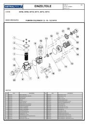
<strong>CDP</strong> WALL-MOUNTED DEHUMIDIFIER – <strong>CDP</strong> SERIES · SWIMMING POOL DEHUMIDIFIER<br />
<strong>DESHUMIDIFICADOR</strong> <strong>MURAL</strong> <strong>CDP</strong> – SERIES <strong>CDP</strong> · <strong>DESHUMIDIFICADOR</strong> DE PISCINA<br />
<strong>DESHUMIDIFICADOR</strong> <strong>MURAL</strong> <strong>CDP</strong><br />
SERIES <strong>CDP</strong> · <strong>DESHUMIDIFICADOR</strong> DE PISCINA<br />
<strong>CDP</strong>-2 <strong>CDP</strong>-2+E <strong>CDP</strong>-2+A <strong>CDP</strong>-2+A PLUS<br />
<strong>CDP</strong>-3 <strong>CDP</strong>-3+E <strong>CDP</strong>-3+A <strong>CDP</strong>-3+A PLUS<br />
<strong>CDP</strong>-4 <strong>CDP</strong>-4+E <strong>CDP</strong>-4+A <strong>CDP</strong>-4+A PLUS<br />
<strong>CDP</strong>-5 <strong>CDP</strong>-5+E <strong>CDP</strong>-5+A <strong>CDP</strong>-5+A PLUS<br />
TECHNICAL MANUAL. START-UP AND OPERATION<br />
MANUAL TÉCNICO. PUESTA EN MARCHA Y FUNCIONAMIENTO<br />
V.2008.03.04
<strong>DESHUMIDIFICADOR</strong> <strong>MURAL</strong> <strong>CDP</strong><br />
SERIES <strong>CDP</strong> · <strong>DESHUMIDIFICADOR</strong> DE PISCINA<br />
<strong>CDP</strong> WALL-MOUNTED DEHUMIDIFIER - <strong>CDP</strong> SERIES · SWIMMING POOL DEHUMIDIFIER<br />
<strong>DESHUMIDIFICADOR</strong> <strong>MURAL</strong> <strong>CDP</strong> - SERIES <strong>CDP</strong> · <strong>DESHUMIDIFICADOR</strong> DE PISCINA<br />
TECHNICAL MANUAL. START-UP AND OPERATION<br />
MANUAL TÉCNICO. PUESTA EN MARCHA Y FUNCIONAMIENTO
INDICE<br />
español<br />
1. INTRODUCCIÓN PÁG.07<br />
2. MODELOS PÁG.08<br />
3. CARACTERÍSTICAS GENERALES PÁG.09<br />
3.1. DESCRIPCIÓN PÁG.09<br />
3.2. DESCRIPCIÓN DEL EQUIPO PÁG.09<br />
3.3. CUADRO ELÉCTRICO PÁG.09<br />
4. CARACTERÍSTICAS TÉCNICAS PÁG.10<br />
5. ESQUEMA DE DIMENSIONES PÁG.11<br />
6. CARACTERÍSTICAS ELÉCTRICAS PÁG.12<br />
7. REGULADOR PÁG.12<br />
8. PRECAUCIONES GENERALES PÁG.14<br />
9. COMPROBACIÓN DEL EMBALAJE PÁG.15<br />
10. CONDICIONES DE TRABAJO PÁG.15<br />
11. REQUISITOS Y OPERACIONES PREVIAS PÁG.16<br />
12. CONEXIONES ELÉCTRICAS PÁG.16<br />
13. CONEXIONES HIDRAÚLICAS PÁG.18<br />
14. OPERACIÓN DE PUESTA EN MARCHA PÁG.18<br />
15. MANTENIMIENTO PREVENTIVO PÁG.18<br />
16. DESESCARCHE PÁG.19<br />
17. AVERÍAS, SUS CAUSAS Y SOLUCIONES PÁG.19<br />
18. CARGA GAS REFRIGERANTE PÁG.20<br />
19. RECICLAJE DEL PRODUCTO PÁG.23<br />
20. CERTIFICADO DE GARANTIA PÁG.24<br />
21. ANEXO 1: ESQUEMA ELÉCTRICO PÁG.25
GENERAL INDEX<br />
english<br />
1. INTRODUCTION PAGE.26<br />
2. MODELS PAGE.27<br />
3. GENERAL CHARACTERISTICS PAGE.28<br />
3.1. DESCRIPTION PAGE.28<br />
3.2. DESCRIPTION OF EQUIPMENT PAGE.28<br />
3.3. ELECTRICAL PANEL PAGE.28<br />
4. TECHNICAL CHARACTERISTICS PAGE.29<br />
5. DIAGRAM OF DIMENSIONS PAGE.30<br />
6. ELECTRICAL CHARACTERISTICS PAGE.31<br />
7. REGULATOR PAGE.31<br />
8. GENERAL PRECAUTIONS PAGE.33<br />
9. PACKAGING INSPECTION PAGE.34<br />
10. OPERATING CONDITIONS PAGE.34<br />
11. REQUIREMENTS AND PROCEDURES PAGE.35<br />
12. ELECTRICAL CONNECTIONS PAGE.35<br />
13. HYDRAULIC CONNECTIONS PAGE.36<br />
14. PROCEDURES AND START-UP PAGE.37<br />
15. PREVENTIVE MAINTENCANCE PAGE.37<br />
16. DEFROSTING PAGE.38<br />
17. TROUBLESHOOTING GUIDE PAGE.38<br />
18. REFRIGERANT GAS CHARGE PAGE.39<br />
19. WARRANTY AND GENERAL CONDITIONS PAGE.42<br />
20. APPENDIX 1: ELECTRICAL PANEL PAGE.44
ESPAÑOL<br />
<strong>DESHUMIDIFICADOR</strong> <strong>MURAL</strong> <strong>CDP</strong><br />
SERIES <strong>CDP</strong><br />
1. INTRODUCCIÓN.<br />
Gracias por confiar en nuestros productos para la climatización de piscinas. La experiencia<br />
acumulada por nuestra compañía durante más de 20 años en el mundo de la climatización de<br />
piscinas ha sido puesta a su servicio en este producto, en el que además incorporamos los avances<br />
técnicos que hacen de su equipo que puede solucionar de forma definitiva la climatización de su<br />
piscina.<br />
Le rogamos dedique unos minutos a la lectura de este manual para que pueda conocer<br />
todos los potenciales de la máquina, y tener en cuenta todas las circunstancias necesarias<br />
para su correcto y duradero funcionamiento.<br />
LE RECOMENDAMOS ANOTE LOS SIGUIENTES DATOS<br />
APARATO<br />
Nº REFERENCIA MODELO<br />
INSTALADOR<br />
NOMBRE<br />
POBLACIÓN<br />
DOMICILIO<br />
TELÉFONO<br />
FECHA DE PUESTA EN MARCHA<br />
USUARIO<br />
NOMBRE<br />
POBLACIÓN<br />
DOMICILIO<br />
TELÉFONO<br />
FECHA DE PUESTA EN MARCHA<br />
(A rellenar por el instalador) SELLO DEL INSTALADOR:<br />
Para todas las máquinas, se deberá cumplimentar<br />
y enviar esta tarjeta de garantía para que entre en vigor<br />
7
ESPAÑOL<br />
2. MODELOS.<br />
CÓDIGO<br />
MODELO<br />
21202 <strong>CDP</strong>-2E<br />
BAT. ELECT. 3 KW<br />
21203 <strong>CDP</strong>-3E BAT. ELECT. 3 KW<br />
PATAS<br />
21204 <strong>CDP</strong>-4E BAT. ELECT. 4 KW<br />
21205 <strong>CDP</strong>-5E BAT. ELECT. 5 KW<br />
21402 <strong>CDP</strong>-2E<br />
BAT. ELECT. 3 KW<br />
21403 <strong>CDP</strong>-3E BAT. ELECT. 3 KW<br />
RUEDAS<br />
21404 <strong>CDP</strong>-4E BAT. ELECT. 4 KW<br />
21405 <strong>CDP</strong>-5E BAT. ELECT. 5 KW<br />
21406 <strong>CDP</strong>-2E<br />
BAT. ELECT. 3 KW<br />
21407 <strong>CDP</strong>-3E BAT. ELECT. 3 KW<br />
PARED<br />
21408 <strong>CDP</strong>-4E BAT. ELECT. 4 KW<br />
21409 <strong>CDP</strong>-5E BAT. ELECT. 5 KW<br />
24771 <strong>CDP</strong>-2A<br />
BAT. AGUA. 3.000 Kcal/h<br />
24772 <strong>CDP</strong>-3A BAT. AGUA. 4.000 Kcal/h<br />
PATAS<br />
24773 <strong>CDP</strong>-4A BAT. AGUA. 5.000 Kcal/h<br />
24774 <strong>CDP</strong>-5A BAT. AGUA. 6.000 Kcal/h<br />
24779 <strong>CDP</strong>-2A<br />
BAT. AGUA. 3.000 Kcal/h<br />
24780 <strong>CDP</strong>-3A BAT. AGUA. 4.000 Kcal/h<br />
PARED<br />
24781 <strong>CDP</strong>-4A BAT. AGUA. 5.000 Kcal/h<br />
24782 <strong>CDP</strong>-5A BAT. AGUA. 6.000 Kcal/h<br />
33939 <strong>CDP</strong>-2A PLUS BAT. AGUA. 5.200 Kcal/h<br />
33940 <strong>CDP</strong>-3A PLUS BAT. AGUA. 7.800 Kcal/h<br />
33941 <strong>CDP</strong>-4A PLUS BAT. AGUA. 10.400 Kcal/h<br />
33942 <strong>CDP</strong>-5A PLUS BAT. AGUA. 10.400 Kcal/h<br />
33943 <strong>CDP</strong>-2E<br />
BAT. ELECT. 3 KW<br />
33944 <strong>CDP</strong>-3E BAT. ELECT. 3 KW<br />
33945 <strong>CDP</strong>-4E BAT. ELECT. 4 KW<br />
33946 <strong>CDP</strong>-5E BAT. ELECT. 5 KW<br />
33947 <strong>CDP</strong>-2A BAT. AGUA. 3.000 Kcal/h<br />
33948 <strong>CDP</strong>-3A BAT. AGUA. 4.000 Kcal/h<br />
EMPOTRADO<br />
33949 <strong>CDP</strong>-4A BAT. AGUA. 5.000 Kcal/h<br />
33950 <strong>CDP</strong>-5A BAT. AGUA. 6.000 Kcal/h<br />
33951 <strong>CDP</strong>-2A PLUS BAT. AGUA. 5.200 Kcal/h<br />
33952 <strong>CDP</strong>-3A PLUS BAT. AGUA. 7.800 Kcal/h<br />
33953 <strong>CDP</strong>-4A PLUS BAT. AGUA. 10.400 Kcal/h<br />
33954 <strong>CDP</strong>-5A PLUS BAT. AGUA. 10.400 Kcal/h<br />
33775 KIT DE RUEDAS INSTALACION <strong>CDP</strong><br />
33776 KIT DE PATAS INSTALACION <strong>CDP</strong><br />
33777 KIT DE PARED INSTALACION <strong>CDP</strong><br />
8
ESPAÑOL<br />
3. CARACTERÍSTICAS GENERALES.<br />
DESCRIPCIÓN.<br />
El deshumidificador <strong>CDP</strong> (Unidad deshumidificadora de piscina) se utiliza en instalaciones donde<br />
se requiere un control de humedad y temperatura individual de la zona, aprovechando el calor<br />
latente de vaporización y el propio rendimiento del equipo en calentar el aire del ambiente de<br />
pequeñas piscinas, bañeras, vestuarios y salas de baño.<br />
DESCRIPCIÓN DEL EQUIPO.<br />
Bomba deshumidificadora mural monoblock construida en robusto y ligero diseño en ABS<br />
Termo conformado resistente a la radiación solar. El color no se degrada, con gran ligereza y<br />
reducidas dimensiones. Equipado con los siguientes elementos:<br />
◙ Batería evaporadora y condensadora monoblock construida en tubería de cobre con<br />
aletas de aluminio lacado (especial para ambientes corrosivos).<br />
◙ Compresor Hermético con protección interna, resistencia de carter y silenciador.<br />
◙ Un circuito frigorífico de cobre nitrogenado, deshidratado y desoxidado.<br />
◙ Ventilador centrífugo con diferentes caudales.<br />
◙ Carga de gas freón R407C inofensivo para el Ozono (Ecológico).<br />
◙ Bandeja de recogida de condensados fabricada en termo conformado ABS.<br />
◙ Maquina mural con opcional de ruedas o patas.<br />
◙ Válvula de expansión con equilibrador de presiones.<br />
Control:<br />
◙ Control a voluntad de la humedad y visualización en todo momento del parámetro.<br />
◙ Minipresostatos de rearme automático.<br />
◙ Termostato de desescarche.<br />
◙ Opcional: Tarjeta horaria.<br />
Montaje y Mantenimiento:<br />
◙ Fácil y rápido montaje y acceso para mantenimiento.<br />
◙ Tomas exteriores de obuses de carga para conectar manómetros.<br />
◙ Fácil limpieza de filtros y de máquina.<br />
Opcionales:<br />
◙ Batería eléctrica con equipo de regulación y termostato de ambiente.<br />
◙ Batería de A.C. válvula de 3 vías incorporada y termostato de ambiente.<br />
◙ Patas o ruedas.<br />
CUADRO ELÉCTRICO<br />
Cuadro eléctrico con control total para garantizar un rendimiento óptimo con un mínimo<br />
consumo de energía en todo momento. La aplicación se basa en el control de una serie de<br />
elementos para mantener unas condiciones de temperatura y humedad en el aire de una instalación<br />
cubierta.<br />
9
ESPAÑOL<br />
El usuario partiendo de un Setpoint de humedad y temperatura, podrá definir el modo de<br />
funcionamiento de la unidad de forma manual o mediante un ajuste programado del día, hora y<br />
minuto del arranque así como de la parada, (opcional) solo las maquinas con tarjeta horaria.<br />
Esta aplicación incorpora además un modo especial para ser configurado por la persona<br />
encargada del mantenimiento y control de la unidad. Éste será capaz de variar parámetros tales<br />
como: diferencial de Setpoint, límites máximos de temperatura y tiempo de funcionamiento,<br />
temperatura de desescarche (ON/OFF), retardos, unidades,...<br />
Incorpora una serie de salidas de alarma reflejadas en el display del FX 05, así como una<br />
salida de alarma a relé.<br />
ENTRADA ANALÓGICA ENTRADA DIGITAL SALIDA DIGITAL SALIDA<br />
ANALOGICA<br />
AI1 Temperatura retorno DI1 Interruptor HP DO1 Alarma general<br />
AI2 Temperatura evaporador DI2 Interruptor LP<br />
AI3 Temperatura resistencias<br />
Válvula 3 vías.<br />
AI4 Humedad relativa<br />
DI4 Térmico compresor<br />
(Interno en el compresor)<br />
4. CARACTERÍSTICAS TÉCNICAS.<br />
DO2 (ON/OFF) Compresor<br />
DO3 (ON/OFF) Ventilador<br />
DO4 (ON/OFF )Resistencia<br />
Válvula 3 vías<br />
MODELO<br />
CARACTERISTICAS<br />
<strong>CDP</strong>-2 <strong>CDP</strong>-3 <strong>CDP</strong>-4 <strong>CDP</strong>-5<br />
Capacidad Deshumidificadora. 2,1 lts/h 3,1 lts/h 4,2 lts/h 5,1 lts/h<br />
Potencia Calorífica w (*) 4.277 W 5.313 W 7.068 W 8.473 W<br />
COMPRESOR<br />
Unidades. 1 1 1 1<br />
Tipo. Hermético Hermético Hermético Hermético<br />
Tensión. 220V II 380V III 220V II 380V III 220V II 380V III 220V II 380V III<br />
Frecuencia. 50 HZ 50 HZ 50 HZ 50 HZ<br />
Consumo. (Amp) 6,01 2 7,04 2,3 9.91 3,3 9,4 4,3<br />
Potencia Nominal. (cv) 1 1 1/4 1 5/8 2<br />
VENTILADOR<br />
Tipo. Centrífugo Centrífugo Centrífugo Centrífugo<br />
Unidades. 1 1 1 1<br />
Caudal. (m3/h) 700 800 1.000 1.200<br />
Consumo. (Amp) 1,1 1,1 1,1 1,1<br />
Voltaje. 220 V 220 V 220 V 220 V<br />
OTROS DATOS<br />
Consumo nominal 7,1 Amp 8,2 Amp 11,01 Amp 10,5 Amp<br />
Gas Refrigerante. R-407C R-407C R-407C R-407C<br />
Peso en Kg + Batería Eléctrica 46 49 64 66<br />
Peso en Kg + Batería A.C. 50 54 69 72<br />
El cálculo de potencias se ha realizado con Temperatura de aire exterior de 28ºC de aire y un 75%<br />
de Humedad.<br />
10
ESPAÑOL<br />
OPCIONALES <strong>CDP</strong>-2+E <strong>CDP</strong>-3+E <strong>CDP</strong>-4+E <strong>CDP</strong>-5+E<br />
Batería Resistencia Eléctrica KW 3 3 4 4<br />
OPCIONALES <strong>CDP</strong>-2+A <strong>CDP</strong>-3+A <strong>CDP</strong>-4+A <strong>CDP</strong>-5+A<br />
Batería Agua Caliente KW 3,5 4,65 5,8 7<br />
Caudal de Primario l/h 150 200 250 300<br />
Caída Presión de Agua m.c.d.a. 0.39 0.67 0.19 0.27<br />
Diámetro Colector Pulgadas ½” ½” ¾” ¾”<br />
<strong>CDP</strong>-2+A <strong>CDP</strong>-3+A <strong>CDP</strong>-4+A <strong>CDP</strong>-5+A<br />
OPCIONALES<br />
PLUS PLUS PLUS PLUS<br />
Batería Agua Caliente KW 6 9 12 12<br />
Caudal de Primario l/h 270 400 600 600<br />
Caída Presión de Agua m.c.d.a. 0,27 0,3 0,35 0,35<br />
Diámetro Colector Pulgadas ¾” ¾” ¾” ¾”<br />
5. ESQUEMA DE DIMENSIONES.<br />
En las dimensiones que se reflejan en el cuadro siguiente están incluidos los diferentes<br />
opcionales existentes.<br />
COTA B<br />
COTA A<br />
COTA E<br />
COTA C<br />
1<br />
2<br />
3<br />
3<br />
1<br />
2<br />
1 y 2 - Conexiones primarias agua caldera<br />
3 - Alimentación eléctrica<br />
DIMENSIONES (mm) <strong>CDP</strong>-2 <strong>CDP</strong>-3 <strong>CDP</strong>-4 <strong>CDP</strong>-5<br />
Largo ( cota A) 1.350 1.350 1.670 1.670<br />
Ancho (cota B) 360 360 360 360<br />
Alto (Cota C) 610 610 610 610<br />
Cuello impulsión 650x100 650x100 900x100 900x100<br />
Cuello Aspiración 650x200 650x200 900x200 900x200<br />
Cuellos (Cota E) 350 350 350 350<br />
11
ESPAÑOL<br />
6. CARACTERÍSTICAS ELÉCTRICAS.<br />
CARACTERISTICAS<br />
MODELO<br />
<strong>CDP</strong>-2+E <strong>CDP</strong>-3+E <strong>CDP</strong>-4+E <strong>CDP</strong>-5+E<br />
Alimentación General<br />
Voltaje. (V) 220 II 380 III 220 II 380 III 220 II 380 III 220 II 380 III<br />
Sección (mm2) 4 4 6 6<br />
Nº de Hilos. 2P+Tierra 4P+Tierra 2P+Tierra 4P+Tierra 2P+Tierra 4P+Tierra 2P+Tierra 4P+Tierra<br />
INTENSIDAD ABSORBIDA (A) <strong>CDP</strong>-2+E <strong>CDP</strong>-3+E <strong>CDP</strong>-4+E <strong>CDP</strong>-5+E<br />
Compresor. 6,01 Amp 2 Amp 7,04 Amp 2,3 Amp 9.91 Amp 3,3 Amp 9,4 Amp 4,3 Amp<br />
Ventilador. 1,1 Amp 1,1 Amp 1,1 Amp 1,1 Amp<br />
Resistencias Eléctricas. 13,6 Amp 4,5 Amp 13,6 Amp 4,5 Amp 18,1 Amp 6 Amp 18,1 Amp 6 Amp<br />
Total 21 Amp 7,6 Amp 22 Amp 7,9 Amp 30 Amp 10 Amp 30 Amp 11,4 Amp<br />
CARACTERISTICAS <strong>CDP</strong>-2 (+A) <strong>CDP</strong>-3(+A) <strong>CDP</strong>-4(+A) <strong>CDP</strong>-5(+A)<br />
Alimentación General<br />
Voltaje. (V) 220 II 380 III 220 II 380 III 220 II 380 III 220 II 380 III<br />
Sección (mm2) 2.5 2.5 2.5 2.5<br />
Nº de Hilos. 2P+Tierra 4P+Tierra 2P+Tierra 4P+Tierra 2P+Tierra 4P+Tierra 2P+Tierra 4P+Tierra<br />
INTENSIDAD ABSORBIDA (A) <strong>CDP</strong>-2 (+A) <strong>CDP</strong>-3 (+A) <strong>CDP</strong>-4 (+A) <strong>CDP</strong>-5 (+A)<br />
Compresor. 6,01 Amp 2 Amp 7,04 Amp 2,3 Amp 9.91 Amp 3,3 Amp 9,4 Amp 4,3 Amp<br />
Ventilador. 1,1 Amp 1,1 Amp 1,1 Amp 1,1 Amp<br />
Total 7,11 Amp 3,1 Amp 8,14 Amp 3,4 Amp 11,01 Amp 4,4 Amp 10,5 Amp 5,4 Amp<br />
7. REGULADOR.<br />
Funciones del frontal:<br />
INSTRUCCIONES DE FUNCIONAMIENTO:<br />
◙ ARRANQUE Y PARADA DE LA UNIDAD: La unidad se arranca por medio de la tecla<br />
superior izquierda ON/OFF. Presionando la tecla durante dos segundos se encenderá la unidad<br />
(aparece una señal en la parte superior izda. del display). Repitiendo la misma operación se<br />
apagará la unidad.<br />
El regulador muestra en el display por defecto la humedad relativa existente en el ambiente.<br />
Pulsando las teclas UP se visualizan además temperatura aire ambiente, el estado de la unidad<br />
(ON/OFF), temperatura del evaporador y temperatura resistencias.<br />
12
ESPAÑOL<br />
◙ MENU USUARIO<br />
Pulsando de forma continua la tecla (ENTER) durante unos 5 segundos se accede al menú<br />
USUARIO. En este menú aparecen los siguientes parámetros:<br />
SET: Permite fijar la temperatura deseada (SET-POINT Temperatura). Una vez alcanzada<br />
la temperatura deseada en el local la función de Calentamiento del deshumidificador parará.<br />
SEH: Permite fijar la humedad relativa deseada (SET POINT Humedad). Una vez<br />
alcanzada la humedad deseada en el local la función de Deshumidificación parará.<br />
OPCIONAL: Solo los equipos con tarjeta horaria.<br />
hh: Ajuste de la hora (del 0 al 23)<br />
nn: Ajuste del minuto (del 0 al 59)<br />
dAY: Ajuste del día de la semana (del 0 al 6) (0 = Lunes / 6 = Domingo)<br />
Pr1: Programación de la unidad (0 = Programada / 1 = Manual)<br />
Sí se elige Manual la máquina funcionará continuamente según los parámetros regulados<br />
en SET y en SHE. No haciendo caso a los parámetros de programación.<br />
Sí se elige Programada la unidad funcionará según los parámetros regulados en SET y en<br />
SHE, siempre dentro de los horarios programados. Fuera de los horarios programados no<br />
funcionará la unidad.<br />
Si elegimos en PR = 1 no hace falta establecer los parámetros siguientes. La unidad ya está<br />
ajustada.<br />
Si elegimos en PR = 0 programar los siguientes parámetros según necesidades.<br />
Ud: Día de funcionamiento de la unidad (1 = Funcionará todos los días. 2 = Funcionará de<br />
Lunes a Viernes. 3 = Funcionará de Lunes a Sábado)<br />
Us: Selección de uno o dos Ciclos de programación ( 1 = Un Ciclo de programación. 2 =<br />
Dos Ciclos de programación)<br />
Si elegimos en Us = 1 solo hará falta programar los parámetros DH1, Dn1, DH2 y Dn2.<br />
Sí elegimos en Us = 2 habrá que programar todos los parámetros siguientes:<br />
DH1: Hora de arranque de la unidad (1º ciclo)<br />
Dn1: Minuto de arranque de la unidad (1º ciclo)<br />
DH2: Hora de parada de la unidad (1º ciclo)<br />
Dn2: Minuto de parada de la unidad (1º ciclo)<br />
DH3: Hora de arranque de la unidad (2º ciclo)<br />
Dn3: Minuto de arranque de la unidad (2º ciclo)<br />
DH4: Hora de parada de la unidad (2º ciclo)<br />
Dn4: Minuto de parada de la unidad (2º ciclo)<br />
13
ESPAÑOL<br />
◙ LEDS INDICADORES:<br />
En el display del regulador se encuentran tres pilotos luminosos con las siguientes<br />
indicaciones empezando de izquierda a derecha:<br />
1. Estado de la unidad (ON/OFF)<br />
2. Desescarche (ON/OFF)<br />
3. Compresor (ON/OFF)<br />
◙ ALARMAS:<br />
La unidad mostrara los siguientes códigos en caso de alarmas:<br />
F1: Fallo sonda aire ambiente.<br />
F2: Fallo sonda evaporador.<br />
F3: Fallo sondas resistencias.<br />
F4: Fallo sonda Humedad Relativa.<br />
HP: Alarma disparo de alta presión.<br />
LP: Alarma disparo de baja presión.<br />
TH: Alarma disparo térmico compresor.<br />
AH: Alarma temperatura aire retorno máxima excedida.<br />
AL: Alarma temperatura aire retorno mínima excedida.<br />
HT: Alarma temperatura máxima de resistencias / Válvula agua superada.<br />
◙ ANULACIÓN ALARMAS:<br />
Para anular las alarmas que se hayan podido producir pulsar simultáneamente unos<br />
segundos las teclas UP & DOWN. Si el problema persiste, la alarma se mostrará inmediatamente.<br />
Mantenimiento:<br />
Limpie la superficie del controlador con un paño suave, agua y jabón. No utilice<br />
detergentes abrasivos, gasolina, alcohol o disolvente.<br />
Advertencias:<br />
El uso del equipo no respetando las instrucciones del fabricante, puede alterar los requisitos<br />
de seguridad del mismo.<br />
8. PRECAUCIONES GENERALES.<br />
Las operaciones de instalación, puesta en marcha y mantenimiento deben ser realizadas por<br />
personal cualificado.<br />
No se debe de instalar estos equipos en entornos inflamables o explosivos.<br />
Para cualquier operación de mantenimiento dentro de la máquina, se tendrá la precaución<br />
de desconectar la corriente eléctrica en el seccionador principal. En las operaciones de<br />
mantenimiento es obligatorio el uso de equipos de protección o seguridad como gafas, guantes, etc.<br />
14
ESPAÑOL<br />
Durante el funcionamiento de la máquina es habitual que las condensaciones que se<br />
producen en la batería evaporadora hagan que salga una cantidad de agua de la máquina que hay<br />
que evacuar. Las máquinas vienen provistas de un tubo de desagüe al efecto en la esquina de la<br />
carcasa trasera, que siempre debe quedar conectada a un aliviadero libre de cualquier obstrucción.<br />
Esta agua de condensación no tiene que ser tratada de una forma especial.<br />
9. COMPROBACIÓN DEL EMBALAJE.<br />
Este equipo, se presenta con un EMBALAJE RECICLABLE capaz de resistir unas duras<br />
condiciones de transporte. No obstante, durante la instalación de la misma se deberá efectuar una<br />
comprobación visual de cualquier desperfecto, de forma que se evite cualquier mal funcionamiento<br />
posterior.<br />
EL FABRICANTE no asumirá responsabilidad en ese caso.<br />
¡ATENCIÓN!<br />
ES MUY IMPORTANTE NO INCLINAR EL EMBALAJE, PARA LO QUE ÉSTE SE<br />
DISEÑÓ CONVENIENTEMENTE. SIEMPRE SE DEBERÁ MANTENER EN POSICIÓN<br />
VERTICAL.<br />
SI LA UNIDAD ESTÁ DAÑADA, O SI EL ENVIO NO ESTA COMPLETO, ANOTAR EN EL<br />
ALBARÁN DE ENTREGA Y ENVIAR UNA RECLAMACIÓN INMEDIATA A LA COMPAÑÍA<br />
QUE REALIZÓ EL ENVÍO.<br />
En su interior encontrará los siguientes elementos:<br />
Equipo de climatización de piscinas<br />
Manual de Instalación.<br />
Garantía.<br />
10. CONDICIONES DE TRABAJO.<br />
Los parámetros físicos y químicos del agua deben de estar en los siguientes valores:<br />
◙ PH..........................................7,2 a 7,8<br />
◙ Cloro residual........................ 1 a 2 ppm<br />
◙ Alcalinidad............................ 80-125 ppm<br />
◙ Sólidos totales disueltos........
ESPAÑOL<br />
11. REQUISITOS Y OPERACIONES PREVIAS.<br />
Es importante que la máquina se deposite en un apoyo horizontal y estable.<br />
Siempre se debe colocar la máquina en posición vertical y en un lugar protegido contra<br />
inundaciones. La garantía no es de aplicación en caso contrario.<br />
El deshumidificador como todo aparato eléctrico debe estar instalado en el local a<br />
tratar a más de 2 mts del vaso de piscina en sentido horizontal (Volumen 2), y 2,5 mts en<br />
sentido vertical.<br />
La máquina está provista de un metro de manguera para la retirada de agua de<br />
condensación.<br />
Durante su funcionamiento aparecerá agua de condensación producida al pasar el aire por<br />
el evaporador. Para ello la máquina dispone un tubo de drenaje en la base. Prevea su evacuación.<br />
Esta máquina está pensada para trabajar en interiores, se debe de comprobar que la entrada<br />
y salida de aire no estén obstruidas. Los obstáculos deben tener una distancia mínima.<br />
Se acompaña a la máquina con un juego de soportes de pared, suelo o ruedas.<br />
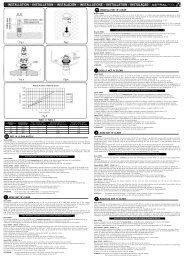
12. CONEXIONES ELÉCTRICAS.<br />
La acometida eléctrica deberá realizarse por el instalador teniendo en cuenta los siguientes puntos:<br />
• Realizar la conexión según el esquema eléctrico incluido en este manual.<br />
• Colocar en la acometida general de fuerza un magnetotérmico curva U, que protegerá la<br />
línea en caso de cortocircuito.<br />
• Colocar en la acometida general de fuerza un interruptor diferencial que protegerá la<br />
instalación contra posibles derivaciones a tierra. La sensibilidad del diferencial será como<br />
mínimo de 30 mA.<br />
• Interruptor diferencial.<br />
• Automáticos o Magnetotérmicos.<br />
En la foto que se representa a continuación se indica esquemáticamente el modo en el que<br />
debe hacer la conexión<br />
16
ESPAÑOL<br />
• Antes de realizar la conexión del equipo se comprobará que la instalación eléctrica está<br />
desconectada y no hay tensión entre las fases de alimentación.<br />
• Conectar los cables de entrada de<br />
corriente a la borna de entrada de la máquina.<br />
• Conectar el cable de toma tierra en la<br />
borna correspondiente para ello.<br />
• Se debe cumplir en todo momento lo que<br />
deja reflejado la normativa vigente en cuanto<br />
a protecciones de las líneas eléctricas contra<br />
defectos y contactos directos o indirectos.<br />
• Verificar el apriete de todas las<br />
conexiones eléctricas.<br />
• Se comprobará que la resistencia eléctrica<br />
entre el suelo y cualquier terminal eléctrico es<br />
superior a 1 megaohmio. En caso contrario no<br />
se pondrá en marcha el equipo hasta que la<br />
perdida eléctrica no sea localizada y reparada.<br />
• En caso de que puedan existir<br />
fluctuaciones en la tensión de entrada, se<br />
recomienda instalar un sistema estabilizador<br />
de tensión para evitar daños al equipo.<br />
Comprobar siempre que la tensión de red se corresponde con la de la máquina en la chapa de<br />
características técnicas.<br />
Se instalarán cables cuya sección cumpla con las normativas actuales e impidan un calentamiento<br />
de estos y una caída de tensión. A titulo orientativo se puede usar esta tabla para longitudes<br />
menores de 5 metros. En todo momento se cumplirá la normativa vigente y los criterios del<br />
proyectista.<br />
ATENCIÓN: no modificar el tarado de los térmicos de protección de motores. En<br />
caso de duda dirigirse a su distribuidor.<br />
MODELO<br />
<strong>CDP</strong>-2+E <strong>CDP</strong>-3+E <strong>CDP</strong>-4+E <strong>CDP</strong>-5+E<br />
Alimentación General<br />
Voltaje. (V) 220 II 380 III 220 II 380 III 220 II 380 III 220 II 380 III<br />
Sección (mm2) 4 4 6 6<br />
Nº de Hilos. 2P+Tierra 4P+Tierra 2P+Tierra 4P+Tierra 2P+Tierra 4P+Tierra 2P+Tierra 4P+Tierra<br />
<strong>CDP</strong>-2 (+A) <strong>CDP</strong>-3(+A) <strong>CDP</strong>-4(+A) <strong>CDP</strong>-5(+A)<br />
Alimentación General<br />
Voltaje. (V) 220 II 380 III 220 II 380 III 220 II 380 III 220 II 380 III<br />
Sección (mm2) 2.5 2.5 2.5 2.5<br />
Nº de Hilos. 2P+Tierra 4P+Tierra 2P+Tierra 4P+Tierra 2P+Tierra 4P+Tierra 2P+Tierra 4P+Tierra<br />
17
ESPAÑOL<br />
13. CONEXIONES HIDRAÚLICAS.<br />
Respetar en todo momento los diámetros de conexión hidráulica especificados para cada<br />
equipo.<br />
Se deben instalar llaves de corte de paso total en cada uno de los elementos hidráulicos de<br />
la instalación y del equipo, de forma tal que permiten aislar cada uno de estos elementos en caso de<br />
necesidad (reparaciones, sustituciones, etc.) sin obligar el vaciado del circuito.<br />
Se colocarán manguitos antivibratorios en la entrada y salida del equipo, para evitar<br />
vibraciones que produzcan fisuras o roturas en la instalación hidráulica.<br />
En la conexión del equipo a la red hidráulica no deberemos forzar los tubos de Cobre. De<br />
esta forma evitaremos la rotura de los mismos.<br />
14. OPERACIÓN DE PUESTA EN MARCHA.<br />
En una primera operación se debe de verificar las conexiones eléctricas, comprobar la<br />
tensión del equipo y la tensión de la red.<br />
Verificar que las conexiones hidráulicas están correctamente realizadas.<br />
Dar tensión al equipo conectando el interruptor general de fuerza externo a la unidad. Una<br />
vez conectada la máquina verificar las intensidades absorbidas por las fases.<br />
Comprobar que el sentido de giro del ventilador es el correcto, en caso contrario invertir las<br />
fases.<br />
Con el equipo en marcha comprobar las intensidades absorbidas por las resistencias y<br />
motores eléctricos, comprobando que no sobrepasan los valores reflejados en la ficha técnica.<br />
Se deben de colocar manómetros de alta y baja presión en el circuito frigorífico y<br />
comprobar la carga de gas (apartado Carga de Gas).<br />
Para realizar la parada del equipo desconectar el interruptor ON/OFF.<br />
15. MANTENIMIENTO PREVENTIVO.<br />
Deberá llevarse un historial de cada elemento atendido en el mantenimiento así como las<br />
actividades o reparaciones realizadas.<br />
Las superficies de las carcasas exteriores pueden limpiarse con un paño y un limpiador no<br />
agresivo.<br />
Realizar cualquier operación de mantenimiento DESCONECTANDO PREVIAMENTE<br />
LA ALIMENTACIÓN DE ELECTRICIDAD A LA MÁQUINA.<br />
ATENCIÓN: cuando la instalación vaya a estar parada durante largos períodos de<br />
tiempo, se aconseja retirar el equipo de la instalación o bien ventilar periódicamente la sala<br />
donde esté ubicado. Esto es debido al ambiente húmedo y clorado al que se ven expuestos los<br />
equipos, lo cual provoca el deterioro acelerado de los componentes electrónicos del mismo.<br />
La garantía no cubre aquellos casos en que el producto quede dañado por exposiciones<br />
prolongadas a un ambiente húmedo y clorado.<br />
Batería evaporadora, condensadora y agua caliente:<br />
Las baterías deben estar libre de obstáculos o polvo excesivo que impidan que el aire<br />
circule apropiadamente a través de la misma. Para efectuar su limpieza, utilice agua sin presión y<br />
detergentes no abrasivos o específicos para ello (consultar al fabricante).<br />
18
ESPAÑOL<br />
Compresor:<br />
Comprobar que el compresor se refrigera convenientemente con el gas circulante<br />
(comprobar la carga de gas. Capitulo 14).<br />
Comprobar que el consumo no ha aumentado.<br />
Comprobar que las presiones de descarga del compresor no sean demasiado altas y que las<br />
presiones de aspiración no sean demasiado bajas.<br />
Verificar que las sujeciones del compresor no están deterioradas.<br />
Verificar que no se forma escarcha en el compresor.<br />
Ventilador:<br />
Comprobar anualmente los caudales del ventilador.<br />
Limpiar la suciedad de los alabes del ventilador así como la rejilla de protección.<br />
Cuadro eléctrico:<br />
Verificar todas las conexiones eléctricas.<br />
Comprobar que no exista sobrecalentamiento en los terminales eléctricos.<br />
Verificar que los sistemas de protección funcionan correctamente.<br />
Verificar que el regulador funcionan correctamente contrastando su lectura con un<br />
termómetro de mercurio (calibración de sonda).<br />
16. DESESCARCHE.<br />
La disminución de temperatura de evaporación por debajo de –5ºC provocará que el<br />
controlador de seguridad de evaporación corte el funcionamiento del compresor, que permanecerá<br />
desactivado hasta el rearme automático.<br />
Este rearme se producirá cuando alcancemos el diferencial de temperatura. Durante este<br />
periodo de tiempo el ventilador estará en funcionamiento.<br />
Cuando la temperatura disminuye y entra en funcionamiento el desescarche se enciende<br />
una alarma en el display.<br />
No es conveniente que la máquina trabaje continuamente en estas condiciones. Recomendamos<br />
que desconecte la máquina cuando no la vaya a utilizar en periodos prolongados o en condiciones<br />
de baja temperatura.<br />
17. AVERÍAS, SUS CAUSAS Y SOLUCIONES.<br />
Las circunstancias por las que su deshumidificador podría no funcionar se detallan a<br />
continuación:<br />
El equipo no se pone en marcha:<br />
La bobina del contactor no se activa: Comprobar que no está quemada en cuyo caso<br />
sustituir. Comprobar los enclavamientos que activan dicha bobina.<br />
Térmico interno abierto: Comprobar el voltaje de la línea. Comprobar que las condiciones<br />
de trabajo son las correctas. Excesivo consumo del compresor. Cortocircuito en la línea del<br />
compresor.<br />
Presostato de baja abierto: Comprobar el funcionamiento de este, sustituyéndolo si fuera<br />
necesario. Comprobar el correcto funcionamiento del ventilador. Comprobar la carga de gas del<br />
equipo (perdida de refrigerante, equipo con fugas) para solucionar esto ver apartado carga de gas.<br />
19
ESPAÑOL<br />
Comprobar que hay buena circulación de aire en la batería de intercambio. Comprobar que<br />
no hay obstrucciones en el circuito frigorífico eliminándola si ocurriera esto. Comprobar el<br />
correcto funcionamiento del capilar, sustituir en caso necesario.<br />
Presostato de alta abierto: Comprobar el funcionamiento de este, sustituyéndolo si fuera<br />
necesario. Comprobar la carga de gas del equipo (exceso de refrigerante) para solucionar esto ver<br />
apartado carga de gas. Comprobar que no hay obstrucciones en el circuito frigorífico eliminándola<br />
si ocurriera esto.<br />
Comprobar que hay una buena circulación de aire por la batería condensadora.<br />
Ciclo de desescarche: Las condiciones de aire ambiente no son adecuadas (temperaturas<br />
demasiado bajas). La máquina no opera en estas condiciones, en este caso el regulador actuará<br />
sobre el compresor parándolo hasta que la temperatura ambiente sobrepase la temperatura mínima<br />
de funcionamiento.<br />
Nivel de aceite bajo:<br />
Manchas de aceite en el equipo: Comprobar fugas en el circuito frigorífico reparándolas,<br />
verificar que los mínipresostatos de alta y baja están bien apretados, en caso de avería sustituirlos.<br />
El equipo funciona en ciclos demasiado cortos:<br />
Presostato de baja se abre y se vuelve a cerrar: Verificar los apartados del punto anterior<br />
“presostato de baja abierto”.<br />
Contacto intermitente en el control de la máquina: Reparar o reemplazar el fallo del control<br />
eléctrico. Comprobar la sonda de humedad.<br />
Comprobar que el equipo no es demasiado grande para la instalación.<br />
El equipo funciona continuamente:<br />
Verificar el funcionamiento del humidostato reparándolo o sustituyéndolo si fuera<br />
necesario.<br />
Contactos del contactor del compresor pegados: Comprobar el funcionamiento de la bobina<br />
del contactor y que no estén quemados los contactos.<br />
La presión en la línea de aspiración es muy baja: Comprobar la carga de gas del equipo<br />
(perdida de refrigerante) para solucionar esto ver apartado de carga de gas. Verificar que no<br />
existen obstrucciones en el circuito frigorífico, capilar, etc, sustituir en caso de avería.<br />
Comprobar que el equipo es lo suficientemente potente para las cargas térmicas existentes.<br />
Ruido excesivo:<br />
Tornillos de sujeción del compresor o ventilador flojos: Apretar todos los elementos de<br />
fijación.<br />
Comprobar el nivel de aceite del compresor.<br />
El compresor produce ruidos parecidos a golpes internos: Comprobar que no se trata de<br />
golpe de líquido revisando el recalentamiento (ver apartado carga de gas).<br />
18. CARGA DE GAS REFRIGERANTE.<br />
Para realizar las tareas que detallamos a continuación se recomienda contactar con un<br />
especialista en equipos de calefacción o aire acondicionado.<br />
Vacío del Circuito Frigorífico:<br />
Es imprescindible antes de realizar la carga de gas hacer el vacío en el circuito frigorífico.<br />
20
ESPAÑOL<br />
-Primera operación de vacío:<br />
1.- Conectar las mangueras del manómetro con los circuitos de la línea de presión de<br />
aspiración (baja presión) y con la línea de presión de descarga (alta presión).<br />
2.- Conectar la línea central del puente del manómetro a la bomba de vacío.<br />
3.- Abrir todas las válvulas, incluyendo la solenoide y la válvula de regulación.<br />
4.- Abrir las válvulas del puente del manómetro (LO = válvula baja / HI = válvula alta).<br />
5.- Poner en funcionamiento la bomba de vacío y esperar hasta que el vacuómetro nos<br />
indique el vacío.<br />
6.- Cerrar todas las válvulas o llaves y desconectar la bomba de vacío.<br />
Carga con Refrigerante:<br />
El equipo emplea refrigerante R-407-C, que es una mezcla de 3 gases diferentes, que se<br />
comportan de forma distinta.<br />
Es por esto que hay que tomar liquido de la botella de refrigerante e introducirlo en el<br />
circuito de baja presión a través de un cargador (sistema de expansión).<br />
Después de haber puesto el circuito frigorífico bajo vacío, después de haber instalado el<br />
cargador y haber conectado las tuberías flexibles de los manómetros a los circuitos de alta y baja<br />
presión, realizaremos la carga de gas.<br />
1.- Conectar la línea central del puente del manómetro a la botella de R-407 por la llave de<br />
líquido.<br />
2.- Abrir la llave de botella y purgar el trozo de tubería.<br />
3.- Abrir la válvula de alta presión.<br />
4-. Presurizar la instalación hasta que se iguale su presión con la de la botella.<br />
5.- Cerrar la válvula del puente de manómetros.<br />
6.- Poner en marcha la máquina. Posiblemente el presostato de baja se activará. Para<br />
continuar con la carga, hay que desconectar el presostato de baja en el cuadro eléctrico<br />
(provisionalmente, mientras que se realiza la carga).<br />
7.- Abrir la válvula de baja hasta que la presión este por encima del valor de disparo del<br />
presostato de baja.<br />
8.- De vez en cuando, cerrar la válvula LO del puente de manómetros para leer la presión<br />
real de aspiración.<br />
9.- Comprobar que la presión de descarga no aumenta por encima de la que se considera<br />
normal para las condiciones de trabajo.<br />
10.- Cuando se haya introducido el peso correcto de refrigerante cerrar la válvula LO.<br />
11.- Cuando la instalación esté trabajando según el diseño y condiciones de trabajo, cerrar<br />
la válvula de botella de carga, desconectar las mangueras de los obuses teniendo cuidado con la<br />
purga de gas.<br />
12.- Colocar los tapones en las tomas de aspiración y descarga del compresor.<br />
Detección de Fugas:<br />
Las fugas pueden aparecer por diversas razones. La incidencia de las fugas puede ser<br />
reducida con una buena cualificación de los operarios y teniendo cuidado en el montaje.<br />
Es importante prestar atención a los puntos que detallamos a continuación:<br />
* Buenas técnicas de soldadura.<br />
* Utilización de antivibratorios.<br />
21
ESPAÑOL<br />
* Utilización de componentes de buena calidad y diseñados para las condiciones de<br />
presión y temperatura de la instalación.<br />
Síntomas de fugas<br />
Las fugas ocasionan la reducción de carga de refrigerante del equipo. Una carga baja puede<br />
ser indicada:<br />
◙<br />
◙<br />
◙<br />
◙<br />
Temperatura del evaporador demasiado baja. Puede ser debido a una obstrucción de la<br />
línea de líquido o mal funcionamiento del capilar. Las consecuencias pueden ser<br />
graves, por ejemplo formación de hielo en el evaporador, etc.<br />
Ciclos muy cortos de funcionamiento del compresor. Esto puede ser debido también a<br />
un mal funcionamiento del humidostato de control.<br />
Compresor sobrecalentado: La falta de gas provoca un caudal insuficiente de vapores<br />
para refrigerar el compresor. Esto puede ocasionar la apertura del térmico interno del<br />
compresor.<br />
El compresor funciona constantemente, no hay refrigerante suficiente como para<br />
obtener las prestaciones adecuadas y al no alcanzar las temperaturas de consigan, el<br />
grupo no para.<br />
En cualquier caso, es mejor no esperar a que aparezcan fugas, es por ello que la instalación<br />
debe inspeccionarse regularmente.<br />
Métodos de Búsqueda de Fugas de Gas:<br />
Existen en el mercado diferentes instrumentos de búsqueda de fugas, aunque no todos son<br />
suficientemente sensibles para ciertos refrigerantes. Es muy importante seleccionar un detector<br />
adecuado para el refrigerante que incorpora el equipo y que se cumplan las operaciones de<br />
mantenimiento.<br />
También se puede utilizar burbujas de jabón (spray de detergente líquido).<br />
Otros métodos como mecheros de antorcha halógena y aditivos en la instalación son<br />
también recomendables para la localización de fugas.<br />
El Gas R-407-C:<br />
El R-407-C es un gas NO INFLAMABLE, no tiene punto de inflamación, no está<br />
sometido, por tanto, a la reglamentación de transporte de gases inflamables.<br />
El R-407-C no es irritante para la piel, los ojos y las mucosas y no produce sensibilidad<br />
cutánea.<br />
Tiene un bajo nivel de toxicidad tanto en exposición única como en exposiciones repetidas,<br />
no es mutágeno ni cancerígeno.<br />
El R-407-C es susceptible de ocasionar congelaciones en contacto del gas licuado con la<br />
piel, debido a su inmediata evaporación.<br />
Como todos los hidrocarburos, halogenados o no, el R-407-C es susceptible, a pesar de su<br />
bajo nivel de toxicidad, de ocasionar un estado preanestésico o anestésico general peligroso si se<br />
inhala una concentración muy elevada en medio cerrado.<br />
22
ESPAÑOL<br />
19. RECICLAJE DEL PRODUCTO<br />
Esta máquina dispone de un gas frigorífico de estado líquido y de componentes eléctricos. Cuando la bomba de calor<br />
finalice su vida útil, deberá ser desmantelada por una empresa habilitada para ello o podrá llevarlo al sitio que destinan<br />
las diferentes entidades locales.<br />
Con objeto de reducir la cantidad de residuos de aparatos eléctricos y electrónicos, la<br />
peligrosidad de los componentes, fomentar la reutilización de los aparatos, la valorización de<br />
sus residuos y determinar una gestión adecuada tratando de mejorar la eficacia de la<br />
protección ambiental, se establecen una serie de normas aplicables a la fabricación del<br />
producto y otras relativas a la correcta gestión ambiental cuando se conviertan en residuo.<br />
Así mismo, se pretende mejorar el comportamiento ambiental de todos los agentes que<br />
intervienen en el ciclo de vida de los aparatos eléctricos y electrónicos, como son los<br />
productores, los distribuidores, los usuarios y en particular, el de aquellos agentes<br />
directamente implicados en la gestión de los residuos derivados de estos aparatos.<br />
A partir del 13 de Agosto de 2005 cuando usted quiera desechar este aparato, tiene dos posibles sistemas de<br />
devolución:<br />
- Si adquiere uno nuevo que sea de tipo equivalente o realice las mismas funciones que el que desecha, podrá<br />
entregarlo, sin coste, en el acto de la compra al distribuidor.<br />
- O podrá llevarlo al sitio que destinen las diferentes entidades locales.<br />
Los aparatos van etiquetados con el símbolo de un “contenedor de basura con ruedas tachado”, este símbolo es<br />
indicativo de la necesaria recogida selectiva y diferenciada del resto de las basuras urbanas.<br />
Posibles efectos sobre el medio ambiente o la salud humana de las sustancias peligrosas que pueda contener.<br />
PVC<br />
El plastificante más usado en las aplicaciones de PVC es el DEHP (dietil-hexil-ftalato). Los ensayos realizados en<br />
diversos labora-torios demuestran que no presenta riesgo alguno para la salud humana en los niveles de<br />
concentración utilizados en los artículos acabados, según informes de la BUA en Alemania (Cuerpo Asesor del Medio<br />
Ambiente Relevante de las sustancias Existentes) y de la BGA (Autoridad Alemana de la Salud) entre otros. Los<br />
resultados de dichos ensayos, unidos a los datos obtenidos en los estudios de biodegradación, confirman que el DEHP<br />
no puede ser considerado peligroso para el medio ambiente. Todos los aditivos utilizados en las formulaciones del<br />
PVC y por lo tanto en las aplicaciones alimentarías, están perfectamente reguladas tanto a nivel europeo como<br />
español.<br />
En Europa la Directiva Comunitaria 90/128/UE modificada posteriormente por la 95/3/UE. A nivel español citemos los<br />
Reales Decretos 1125/1982 del 30 de Abril, el cual fue confirmado por el 1042/1997 del 27 de Junio de ese mismo año.<br />
La moderna tecnología aplicada desde hace años en las plantas de producción del PVC, permite afirmar que éstas no<br />
presentan ningún peligro para el medio ambiente, los análisis de ciclo de vida (ACV) demuestran que el impacto<br />
medioambiental del PVC es equivalente o incluso más favorable que el de otros materiales.<br />
TITANIO<br />
Efectos sobre la salud. El titanio elemental y el dióxido de titanio tienen un nivel bajo de toxicidad. Una exposición<br />
excesiva en los humanos al dióxido de titanio por inhalación puede resultar en ligeros cambios en los pulmones.<br />
Efectos de la sobreexposición al polvo de titanio. La inhalación del polvo puede causar tirantez y dolor en el pecho,<br />
tos, y dificultad para respirar. El contacto con la piel y los ojos puede provocar irritación. Vías de entrada: inhalación,<br />
contacto con la piel, con-tacto con los ojos.<br />
Carcinogenicidad. La agencia internacional para la investigación del cáncer (IARC) ha incluido el dióxido de titanio en<br />
el grupo 3 (el agente no es clasificable con respecto a su carcinogenicidad en humanos).<br />
Efectos ambientales. Baja toxicidad. No se han documentado efectos ambientales negativos del titanio<br />
23
ESPAÑOL<br />
20. CERTIFICADO DE GARANTÍA<br />
1. ASPECTOS GENERALES<br />
1.1 De acuerdo con estas disposiciones, el vendedor garantiza que el producto correspondiente a esta garantía (“el<br />
producto”) no presenta ninguna falta de conformidad en el momento de su entrega.<br />
1.2 El período de garantía para el producto es de dos (2) años, y se calculará desde el momento de entrega al<br />
comprador.<br />
1.3 Si se produjera una falta de conformidad del Producto y el comprador lo notificase al vendedor durante el Período<br />
de Garantía, el vendedor deberá reparar o sustituir el Producto a su propio coste en el lugar donde considere oportuno,<br />
salvo que ello sea imposible o desproporcionado.<br />
1.4 Cuando no se pueda reparar ni sustituir el Producto, el comprador podrá solicitar una reducción proporcional del<br />
precio o, si la falta de conformidad es suficientemente importante, la resolución del contrato de venta.<br />
1.5 Las partes sustituidas o reparadas en virtud de esta garantía no ampliarán el plazo de la garantía del Producto<br />
original, si bien dispondrán de su propia garantía.<br />
1.6 Para la efectividad de la presente garantía, el comprador deberá acreditar la fecha de adquisición y entrega del<br />
Producto.<br />
1.7 Cuando hayan transcurrido más de seis meses desde la entrega del Producto al comprador y éste alegue falta de<br />
conformidad de aquél, el comprador deberá acreditar el origen y la existencia del defecto alegado.<br />
1.8 El presente Certificado de Garantía no limita o prejuzga los derechos que correspondan a los consumidores en<br />
virtud de normas nacionales de carácter imperativo.<br />
2. CONDICIONES PARTICULARES<br />
2.1 La presente garantía cubre los productos a que hace referencia este manual.<br />
2.2 El presente Certificado de Garantía será de aplicación únicamente en los países de la Unión Europea.<br />
2.3 Para la eficacia de esta garantía, el comprador deberá seguir estrictamente las indicaciones del fabricante incluidas<br />
en la documentación que acompaña al Producto, cuando ésta resulte aplicable según la gama y modelo del Producto.<br />
2.4 Cuando se especifique un calendario para la sustitución, mantenimiento o limpieza de ciertas piezas o<br />
componentes del Producto, la Garantía sólo será válida, cuando se haya seguido dicho calendario correctamente.<br />
3. LIMITACIONES<br />
3.1 La presente garantía únicamente será de aplicación en aquellas ventas realizadas a consumidores, entendiéndose<br />
“consumidor”, aquella persona que adquiere el Producto con fines que no entran en el ámbito de su actividad<br />
profesional.<br />
3.2 No se otorga ninguna garantía respecto del normal desgaste por uso del Producto. En relación con las piezas,<br />
componentes y/o materiales fungibles o consumibles como pilas, bombillas etc, se estará a lo dispuesto en la<br />
documentación que acompañe al Producto, en su caso.<br />
3.3 La garantía no cubre aquellos casos en que el Producto: (I) haya sido objeto de un trato incorrecto; (II) haya sido<br />
reparado, mantenido o manipulado por persona no autorizada o (III) haya sido reparado o mantenido con piezas no<br />
originales.<br />
Cuando la falta de conformidad del Producto sea consecuencia de una incorrecta instalación o puesta en marcha, la<br />
presente garantía sólo responderá cuando dicha instalación o puesta en marcha esté incluida en el contrato de<br />
compra-venta del Producto y haya sido realizada por el vendedor o bajo su responsabilidad<br />
PRODUCTOS: <strong>DESHUMIDIFICADOR</strong> DE PISCINA<br />
DECLARACIÓN CE DE CONFORMIDAD<br />
Los productos arriba enumerados se hallan conformes con:<br />
Directiva de seguridad de máquinas 98/37/CEE<br />
Directiva de compatibilidad electromagnética 89/336/CEE<br />
Directiva de equipos de baja tensión 97/23/CEE<br />
Directiva de equipos a presión 97/23/CEE<br />
Normativa europea EN 603354-2-41<br />
Directiva RoHS 2002/95 CE<br />
Directiva RAEE 2002/96 CE<br />
24
ESPAÑOL<br />
21. ANEXO 1: ESQUEMA ELÉCTRICO.<br />
LEYENDA<br />
CÓDIGO<br />
AI1<br />
AI2<br />
AI3<br />
AI4<br />
DI1<br />
DI2<br />
DI4<br />
DESCRIPCIÓN<br />
SENSOR TEMPERATURA RETORNO<br />
SENSOR TEMPERATURA EVAPORADOR<br />
SENSOR TEMPERATURA RESISTENCIAS<br />
SENSOR HUMEDAD<br />
ALTA PRESIÓN<br />
BAJA PRESIÓN<br />
TÉRMICO COMPRESOR<br />
CONTACTOR<br />
COMPRESOR<br />
Conectado internamente<br />
Conectado internamente<br />
C1<br />
DO1<br />
DO2<br />
C2/3 C4/5 C6<br />
DO3 DO4 DO5 DO6<br />
AI4<br />
AI3 AI2 AI1 com<br />
24V 24V DI1 DI2 DI3 DI4 DI5 DI AO+ AO<br />
com com<br />
(-) (+)<br />
AI3 AI2 AI1<br />
ALARMA<br />
CONTACTOR<br />
VENTILADOR<br />
RESISTENCIA / V.3 VIAS<br />
CONVERSOR<br />
TRADUCTOR<br />
0-10V<br />
TRANSFORMADOR<br />
24V AC<br />
220V AC<br />
MINIPRESOSTATO ALTA<br />
MINIPRESOSTATO BAJA<br />
TERMICO COMPRESOR<br />
AI4<br />
25
ENGLISH<br />
<strong>CDP</strong> WALL-MOUNTED DEHUMIDIFIER<br />
<strong>CDP</strong> SERIES<br />
1. INTRODUCTION.<br />
Thank you for trusting in our products for the heating and cooling systems for swimming<br />
pool. Through this product, we offer you our extensive experience of over 20 years in the heated<br />
swimming pool sector, where we strive to incorporate the latest technological innovations into all<br />
our products, making this equipment the definitive solution to your heated swimming pool needs.<br />
Please read this manual carefully. It will help you to learn the full potential of the<br />
equipment as well as the necessary procedures for its long-lasting and correct operation.<br />
WE RECOMMEND YOU FILL IN THE FOLLOWING INFORMATION<br />
UNIT<br />
SERIAL NUMBER<br />
MODEL<br />
INSTALLER<br />
NAME<br />
TOWN<br />
ADDRESS<br />
TELEPHONE<br />
START-UP DATE<br />
USER<br />
NAME<br />
TOWN<br />
ADDRESS<br />
TELEPHONE<br />
START-UP DATE<br />
(To be filled by the installer)<br />
INSTALLER´S STAMP:<br />
This warranty card should be filled and sent for<br />
all machines in order to be fully appicable<br />
26
ENGLISH<br />
2. MODELS.<br />
CODE<br />
MODEL<br />
21202 <strong>CDP</strong>-2E<br />
ELECT. BAT. 3 KW<br />
21203 <strong>CDP</strong>-3E ELECT. BAT. 3 KW<br />
WITH LEGS<br />
21204 <strong>CDP</strong>-4E ELECT. BAT. 4 KW<br />
21205 <strong>CDP</strong>-5E ELECT. BAT. 5 KW<br />
21402 <strong>CDP</strong>-2E<br />
ELECT. BAT. 3 KW<br />
21403 <strong>CDP</strong>-3E ELECT. BAT. 3 KW<br />
WITH WHEELS<br />
21404 <strong>CDP</strong>-4E ELECT. BAT. 4 KW<br />
21405 <strong>CDP</strong>-5E ELECT. BAT. 5 KW<br />
21406 <strong>CDP</strong>-2E<br />
ELECT. BAT. 3 KW<br />
21407 <strong>CDP</strong>-3E ELECT. BAT. 3 KW<br />
WALL-MOUNTED<br />
21408 <strong>CDP</strong>-4E ELECT. BAT. 4 KW<br />
21409 <strong>CDP</strong>-5E ELECT. BAT. 5 KW<br />
24771 <strong>CDP</strong>-2A<br />
WATER. BAT. 3.000 Kcal/h<br />
24772 <strong>CDP</strong>-3A WATER. BAT. 4.000 Kcal/h<br />
WITH LEGS<br />
24773 <strong>CDP</strong>-4A WATER. BAT. 5.000 Kcal/h<br />
24774 <strong>CDP</strong>-5A WATER. BAT. 6.000 Kcal/h<br />
24779 <strong>CDP</strong>-2A<br />
WATER. BAT. 3.000 Kcal/h<br />
24780 <strong>CDP</strong>-3A WATER. BAT. 4.000 Kcal/h<br />
WALL-MOUNTED<br />
24781 <strong>CDP</strong>-4A WATER. BAT. 5.000 Kcal/h<br />
24782 <strong>CDP</strong>-5A WATER. BAT. 6.000 Kcal/h<br />
33939 <strong>CDP</strong>-2A PLUS WATER. BAT. 5.200 Kcal/h<br />
33940 <strong>CDP</strong>-3A PLUS WATER. BAT. 7.800 Kcal/h<br />
33941 <strong>CDP</strong>-4A PLUS WATER. BAT. 10.400 Kcal/h<br />
33942 <strong>CDP</strong>-5A PLUS WATER. BAT. 10.400 Kcal/h<br />
33943 <strong>CDP</strong>-2E<br />
ELECT. BAT. 3 KW<br />
33944 <strong>CDP</strong>-3E ELECT. BAT. 3 KW<br />
33945 <strong>CDP</strong>-4E ELECT. BAT. 4 KW<br />
33946 <strong>CDP</strong>-5E ELECT. BAT. 5 KW<br />
33947 <strong>CDP</strong>-2A WATER. BAT. 3.000 Kcal/h<br />
33948 <strong>CDP</strong>-3A WATER. BAT. 4.000 Kcal/h<br />
RECESSED<br />
33949 <strong>CDP</strong>-4A WATER. BAT. 5.000 Kcal/h<br />
33950 <strong>CDP</strong>-5A WATER. BAT. 6.000 Kcal/h<br />
33951 <strong>CDP</strong>-2A PLUS WATER. BAT. 3.000 Kcal/h<br />
33952 <strong>CDP</strong>-3A PLUS WATER. BAT. 4.000 Kcal/h<br />
33953 <strong>CDP</strong>-4A PLUS WATER. BAT. 5.000 Kcal/h<br />
33954 <strong>CDP</strong>-5A PLUS WATER. BAT. 6.000 Kcal/h<br />
33775 CPD WHEEL INSTALLATION KIT<br />
33776 <strong>CDP</strong> LEG INSTALLATION KIT<br />
33777 <strong>CDP</strong> WALL INSTALLATION KIT<br />
27
ENGLISH<br />
3. GENERAL CHARACTERISTICS.<br />
3.1. DESCRIPTION.<br />
The <strong>CDP</strong> dehumidifier (dehumidifying unit for swimming pools) is used in facilities requiring<br />
humidity control and individualised temperature management, taking advantage of the existing<br />
heat vapours and the equipment's heat output in order to warm the ambient air in small swimming<br />
pools, bathtubs, dressing rooms and bathrooms.<br />
3.2. DESCRIPTION OF THE EQUIPMENT.<br />
Wall-mounted monoblock dehumidifying pump constructed of robust and lightweight thermalmoulded<br />
ABS plastic, resistant to solar radiation. The colour does not fade, and it has a reduced<br />
size and is very lightweight. Equipped with the following:<br />
◙ Monoblock evaporating and condensing coil constructed of copper tubing including<br />
tempered aluminium fins (special for corrosive surroundings)<br />
◙ Hermetically sealed compressor including internal protection, positive temperature<br />
coefficient device and silencer.<br />
◙ A cooling circuit made of heavy wall copper tubing, processed to repel rust.<br />
◙ Centrifugal fan with various flow levels.<br />
◙ Freon refrigerant gas R407C which is not harmful for the ozone (Ecological).<br />
◙ Condensation plenum chamber made of thermal-moulded ABS plastic.<br />
◙ Wall-mounted unit with legs or wheel mounting option.<br />
◙ Expansion valve with pressure equaliser.<br />
Control:<br />
◙ Full control of humidity and complete visualisation of all parameters.<br />
◙ Mini pressure switches with automatic reset.<br />
◙ Defrosting thermostat.<br />
◙ Optional: time control card.<br />
Assembly and Maintenance:<br />
◙ Quick and easy set-up and parts easily accessible for maintenance.<br />
◙ External outlets for fitting and charging pressure gauges.<br />
◙ Easy filter and machine cleaning.<br />
Options:<br />
◙ Electrical battery with built-in regulation and atmospheric thermostat.<br />
◙ A.C. battery with built-in three-way valve and atmospheric thermostat.<br />
◙ Legs or wheels.<br />
3.3. ELECTRICAL PANEL.<br />
Electrical control panel for complete process control and to guarantee optimum<br />
performance with minimum power consumption at all times. The process control is based on<br />
various elements which are used to maintain temperature conditions and humidity in the air of a<br />
covered facility.<br />
28
ENGLISH<br />
Starting from a preset humidity and temperature Setpoint, the user can modify the operation<br />
of the unit manually or by setting the program to start or stop on a specified day, hour and minute<br />
(optional - for machines equipped with time card).<br />
This application also offers the possibility of a special mode of programming which can be<br />
done by the personnel in charge of the maintenance and control of the equipment. This personnel<br />
will be able to modify various parameters such as: Setpoint differential, maximum temperature and<br />
time limits, defrosting temperatures (ON/OFF), delayed operation, units, etc…<br />
alarm.<br />
It also includes various alarms which can be viewed on the FX 05 display, as well as a relay<br />
ANALOG ENTRY DIGITAL ENTRY DIGITAL OUTPUT ANALOG<br />
OUTPUT<br />
AI1 Return Temperature DI1 HP Switch DO1 General alarm<br />
AI2 Condenser Temperature DI2 LP Switch DO2(ON/OFF) Compressor<br />
AI3 3-way Resistance Valve<br />
Temperature<br />
AI4 Relative Humidity<br />
DI4 Thermal compressor<br />
(Inside the compressor)<br />
4. TECHNICAL CHARACTERISTICS.<br />
DO3(ON/OFF) Fan<br />
DO4 (ON/OFF )3-way Resistance<br />
Valve<br />
MODEL<br />
CARACTERISTICS<br />
<strong>CDP</strong>-2 <strong>CDP</strong>-3 <strong>CDP</strong>-4 <strong>CDP</strong>-5<br />
Dehumidification Capacity 2,1 lts/h 3,1 lts/h 4,2 lts/h 5,1 lts/h<br />
Power Output w (*) 4.277 W 5.313 W 7.068 W 8.473 W<br />
COMPRESSOR<br />
Units. 1 1 1 1<br />
Type Hermetic Hermetic Hermetic Hermetic<br />
Voltage. 220V II 380V III 220V II 380V III 220V II 380V III 220V II 380V III<br />
Frequency. 50 HZ 50 HZ 50 HZ 50 HZ<br />
Consumption. (Amp) 6,01 2 7,04 2,3 9.91 3,3 9,4 4,3<br />
Nominal Power. (cv) 1 1 1/4 1 5/8 2<br />
FAN<br />
Type. Centrifugal Centrifugal Centrifugal Centrifugal<br />
Units. 1 1 1 1<br />
Flow. (m3/h) 700 800 1.000 1.200<br />
Consumption. (Amp) 1,1 1,1 1,1 1,1<br />
Voltage. 220 V 220 V 220 V 220 V<br />
OTHER DATA<br />
Nominal consumption 7,1 Amp 8,2 Amp 11,01 Amp 10,5 Amp<br />
Refrigerant. R-407C R-407C R-407C R-407C<br />
Weight in Kg + Electric Battery 46 49 64 66<br />
Weight in Kg + A.C. Battery 50 54 69 72<br />
* The calculation of power output was done based on exterior air Temperature of 28 ºC and 75%<br />
Humidity.<br />
29
ENGLISH<br />
OPTIONS <strong>CDP</strong>-2+E <strong>CDP</strong>-3+E <strong>CDP</strong>-4+E <strong>CDP</strong>-5+E<br />
Electrical Battery KW 3 3 4 4<br />
OPTIONS <strong>CDP</strong>-2+A <strong>CDP</strong>-3+A <strong>CDP</strong>-4+A <strong>CDP</strong>-5+A<br />
Hot WATER Battery KW 3,5 4,65 5,8 7<br />
Primary Flow l/h 150 200 250 300<br />
Water Pressure m.c.d.a. 0.39 0.67 0.19 0.27<br />
Manifold Diameter Inches ½” ½” ¾” ¾”<br />
<strong>CDP</strong>-2+A <strong>CDP</strong>-3+A <strong>CDP</strong>-4+A <strong>CDP</strong>-5+A<br />
OPTIONS<br />
PLUS PLUS PLUS PLUS<br />
Hot Water Battery KW 6 9 12 12<br />
Primary Flow l/h 270 400 600 600<br />
Water Pressure m.c.d.a. 0,27 0,3 0,35 0,35<br />
Manifold Diameter Inches ¾” ¾” ¾” ¾”<br />
5. DIAGRAMS OF DIMENSIONS.<br />
The different options available are reflected in the diagrams of the dimensions shown<br />
below.<br />
SIDE B<br />
SIDE A<br />
SIDE E<br />
SIDE C<br />
1<br />
2<br />
3<br />
3<br />
1<br />
2<br />
1 and 2 - Water heater primary connections<br />
3 - Power supply<br />
DIMENSIONS (mm) <strong>CDP</strong>-2 <strong>CDP</strong>-3 <strong>CDP</strong>-4 <strong>CDP</strong>-5<br />
Length ( side A) 1.350 1.350 1.670 1.670<br />
Width (side B) 360 360 360 360<br />
Height (side C) 610 610 610 610<br />
Supply duct 650x100 650x100 900x100 900x100<br />
Return duct 650x200 650x200 900x200 900x200<br />
Ducts (side E) 350 350 350 350<br />
30
ENGLISH<br />
6. ELECTRICAL CHARACTERISTICS.<br />
CHARACTERISTICS<br />
MODEL<br />
<strong>CDP</strong>-2+E <strong>CDP</strong>-3+E <strong>CDP</strong>-4+E <strong>CDP</strong>-5+E<br />
General Power Supply<br />
Voltage. (V) 220 II 380 III 220 II 380 III 220 II 380 III 220 II 380 III<br />
Section (mm2) 4 4 6 6<br />
No. of wires<br />
2P+ 4P+ 2P+ 4P+ 2P+ 4P+ 2P+ 4P+<br />
Ground Ground Ground Ground Ground Ground Ground Ground<br />
ABSORBED INTENSITY (A) <strong>CDP</strong>-2+E <strong>CDP</strong>-3+E <strong>CDP</strong>-4+E <strong>CDP</strong>-5+E<br />
Compressor. 6,01 Amp 2 Amp 7,04 Amp 2,3 Amp 9.91 Amp 3,3 Amp 9,4 Amp 4,3 Amp<br />
Fan. 1,1 Amp 1,1 Amp 1,1 Amp 1,1 Amp<br />
Electric Resistance. 13,6 Amp 4,5 Amp 13,6 Amp 4,5 Amp 18,1 Amp 6 Amp 18,1 Amp 6 Amp<br />
Total 21 Amp 7,6 Amp 22 Amp 7,9 Amp 30 Amp 10 Amp 30 Amp 11,4 Amp<br />
CHARACTERISTICS <strong>CDP</strong>-2 (+A) <strong>CDP</strong>-3(+A) <strong>CDP</strong>-4(+A) <strong>CDP</strong>-5(+A)<br />
General Power Supply<br />
Voltage. (V) 220 II 380 III 220 II 380 III 220 II 380 III 220 II 380 III<br />
Section (mm2) 2.5 2.5 2.5 2.5<br />
No. of wires<br />
2P+ 4P+ 2P+ 4P+ 2P+ 4P+ 2P+ 4P+<br />
Ground Ground Ground Ground Ground Ground Ground Ground<br />
ABSORBED INTENSITY (A) <strong>CDP</strong>-2 (+A) <strong>CDP</strong>-3 (+A) <strong>CDP</strong>-4 (+A) <strong>CDP</strong>-5 (+A)<br />
Compressor. 6,01 Amp 2 Amp 7,04 Amp 2,3 Amp 9.91 Amp 3,3 Amp 9,4 Amp 4,3 Amp<br />
Fan. 1,1 Amp 1,1 Amp 1,1 Amp 1,1 Amp<br />
Total 7,11 Amp 3,1 Amp 8,14 Amp 3,4 Amp 11,01 Amp 4,4 Amp 10,5 Amp 5,4 Amp<br />
7. REGULATOR.<br />
Frontal features:<br />
INSTRUCTIONS FOR OPERATION:<br />
◙ TURNING THE UNIT ON AND OFF: The unit is turned on by pressing the ON/OFF<br />
button on the upper left side of the display. Pressing the button for two seconds will turn the unit<br />
on (a lighted signal will appear on the upper left side of the display). Repeating this procedure will<br />
turn off the unit.<br />
31
ENGLISH<br />
The regulator will display the relative humidity of the atmosphere by defect. By pressing<br />
the UP button, you can also visualise ambient air temperature, the condition of the unit (ON/OFF),<br />
and the resistor temperatures.<br />
◙ USER MENU<br />
By pressing the (ENTER) button for 5 seconds, you can access the USER menu. This menu<br />
displays the following parameters:<br />
SET: Allows for the setting of a specific temperature (SET-POINT Temperature). Once the<br />
specific temperature is reached in the area, the Heating function of the Dehumidifier will turn off.<br />
SEH: Allows for the setting of a specific relative humidity (SET-POINT Humidity). Once<br />
the specific humidity is reached in the area, the Dehumidifying function will turn off.<br />
OPCIONAL: Only for units with time card.<br />
hh: Adjusts the hour (from 0 to 23)<br />
nn: Adjusts the minutes (from 0 to 59)<br />
dAY: Adjusts the day of the week (from 0 to 6) (0 = Monday / 6 = Sunday)<br />
Pr1: Unit programming (0 = Programmed / 1 = Manual)<br />
If Manual operation is chosen, the machine will operate continuously, following the<br />
specified parameters regulated by SET and SEH. Factory setting will be ignored.<br />
If Programmed operation is chosen, the machine will operate following factory settings of<br />
SET and SEH, within the specified times. Outside of these times, the machine will not operate.<br />
If PR = 1 is chosen, it is not necessary to establish any parameters. The machine is already<br />
adjusted.<br />
If PR = 0 is chosen, the following parameters must be programmed depending on your<br />
needs.<br />
Ud: Days the unit should operate (1 = Every day. 2 = From Monday to Friday. 3 = From<br />
Monday to Saturday).<br />
Us: Selection of one or two Programme Cycles (1 = One Programme Cycle. 2 = Two<br />
Programme Cycles).<br />
If Us = 1 is chosen, only the DH1, Dn1, DH2 and Dn2 parameters need be programmed.<br />
If Us = 2 is chosen, the following parameters will need to be programmed:<br />
DH1: Hour of unit start-up (1st cycle)<br />
Dn1: Minute of unit start-up (1st cycle)<br />
DH2: Hour of unit shutdown (1st cycle)<br />
Dn2: Minute of unit shutdown (1st cycle)<br />
DH3: Hour of unit start-up (2nd cycle)<br />
Dn3: Minute of unit start-up (2nd cycle)<br />
DH4: Hour of unit shutdown (2nd cycle)<br />
Dn4: Minute of unit shutdown (2nd cycle)<br />
32
ENGLISH<br />
◙ INDICATOR LEDS:<br />
Located on the regulator display, you will find three indicator leds indicating the following,<br />
from left to right:<br />
4. Condition of the unit (ON/OFF)<br />
5. Defrosting (ON/OFF)<br />
6. Compressor (ON/OFF)<br />
◙ ALARMS:<br />
The unit will display the following alarm codes when necessary:<br />
F1: Failure ambient air indicator.<br />
F2: Failure evaporation indicator.<br />
F3: Failure resistance indicator.<br />
F4: Failure Relative Humidity indicator.<br />
HP: High pressure alarm.<br />
LP: Low pressure alarm.<br />
TH: Thermal compressor alarm.<br />
AH: Maximum air return exceeded alarm.<br />
AL: Minimum air return exceeded alarm.<br />
HT: Maximum resistance temperature exceeded / Water valve exceeded.<br />
◙ ALARM CANCELLATION:<br />
In order to cancel the alarm codes which may be displayed, push the UP & DOWN buttons<br />
simultaneously for a few seconds. If the problem still exists, the alarm will show it immediately.<br />
Maintenance:<br />
Clean the surface of the controlling unit with a soft cloth, soap and water. Never use<br />
abrasive products, gasoline, alcohol or solvent.<br />
Warnings:<br />
Not respecting the manufacturer's instructions regarding the use of this equipment may<br />
compromise the operation and safety of the equipment.<br />
8. GENERAL PRECAUTIONS.<br />
The installation, start-up and maintenance should be done by qualified personnel only.<br />
This equipment should not be exposed to inflammable substances or explosives.<br />
For any maintenance work done on the inside of the machine, proper care and precaution<br />
should be taken to disconnect the main equipment from the power supply. For these types of<br />
operations, the use of protective equipment such as goggles and gloves is required.<br />
33
ENGLISH<br />
During operation of the equipment, it is normal that the condensation produced by the<br />
evaporation unit will produce a certain quantity of water which will have to be evacuated. The<br />
machines have an outlet tube for this reason on the corner of the back cover which should always<br />
be free of any obstruction and connected to a drain.<br />
This condensation water does not have to be treated in any special manner.<br />
9. PACKAGING INSPECTION.<br />
This equipment is packaged using RECYCLABLE MATERIALS which can withstand<br />
even the most difficult transportation conditions. Nevertheless, an inspection of the packaging<br />
should be done upon receipt of the equipment in order to check for any damages, and to avoid<br />
incorrect operation of the equipment.<br />
Talleres del Agua will not be held responsible in this case.<br />
¡WARNING!<br />
IT IS VERY IMPORTANT TO KEEP THE PACKAGED EQUIPMENT UPRIGHT, AND THE<br />
PACKAGING HAS BEEN SPECIFICALLY DESIGNED FOR THIS. ALWAYS MAINTAIN IT IN A<br />
VERTICAL POSITION.<br />
IF THE UNIT IS DAMAGED, OR THE CONSIGNMENT IS INCOMPLETE, MAKE A NOTE<br />
OF IT ON THE CARRIER'S BILL OF LADING AND IMMEDIATELY MAKE A CLAIM TO THE<br />
COMPANY IN CHARGE OF SHIPPING.<br />
The package includes the following elements:<br />
Heating and cooling swimming pool’s equipment<br />
Owner's Manual.<br />
Warranty.<br />
10. OPERATING CONDITIONS.<br />
Water physical and chemical parameters must be in between:<br />
◙ PH 7.2 to 7.8<br />
◙ Residual Cl<br />
1 to 2 ppm<br />
◙ Alkalinity<br />
80 to 125 ppm<br />
◙ Solids<br />
Lower than 3000 mg/l<br />
◙ Ca<br />
200 – 300 ppm<br />
Normal ambient conditions for operation are:<br />
◙ Air temp. installation: 28º C<br />
◙ Humidity: 75%<br />
The limits established for working conditions in order to guarantee the proper operation of<br />
the equipment are:<br />
◙ Minimum air temp. installation: 18ºC<br />
Temperature below this will activate the alarm.<br />
The operating conditions will affect the output of the equipment.<br />
34
ENGLISH<br />
11. REQUIREMENTS AND PROCEDURES.<br />
It is important that the equipment be installed on stable, horizontal ground.<br />
Always place the equipment vertically and far away from dangers of inundation. If not, the<br />
warranty will be voided.<br />
Like any other electrical equipment, the dehumidifier should be installed more than 2<br />
meters, horizontally, away from the pool (Volume 2) and 2,5 meters, vertically, away from<br />
the pool.<br />
The machine is equipped with a one-meter hose for the elimination of condensed water.<br />
During operation, condensed water will appear, produced by the passing of air through the<br />
evaporation unit. For this, the machine is equipped with a drainage tube on the base. Please plan<br />
ahead for the drainage.<br />
This equipment is designed for interiors, the air inlets and outlets should be free of<br />
obstruction. Obstacles should be maintained at a distance.<br />
The equipment includes a support kit for wall, floor or wheels.<br />
12. ELECTRICAL CONNECTIONS.<br />
The electrical installation should be done by qualified professionals, keeping in mind the following<br />
points:<br />
Connect the equipment following the wiring diagram included in this manual.<br />
Place a U-curve thermal-magnetic circuit breaker in the general power connection to<br />
protect the line in the case of a short in the circuit.<br />
Place a differential circuit breaker in the general power connection to protect the<br />
equipment from possible grounding problems. The differential breaker should be minimum<br />
30 mA.<br />
◙ Differential circuit breaker.<br />
◙ Circuit breakers or thermal-magnetic circuit breaker.<br />
The picture shown below is a diagram of how the connections should be made.<br />
35
ENGLISH<br />
Before installing the connections, be sure to<br />
disconnect the electricity so that the power<br />
supply is turned off.<br />
Connect the power supply wires to the<br />
machine's input terminal.<br />
Connect the grounding wire to its<br />
corresponding terminal.<br />
All local and national electricity codes<br />
concerning the protection of defects in electric<br />
power lines should be respected at all times<br />
during the electrical installation.<br />
Verify the torque of all electrical<br />
connections.<br />
The electrical resistance between the<br />
ground and any electric terminal will be verified<br />
to be over 1 megaohm.<br />
In the case of fluctuations in the power<br />
supply, a power supply stabilising system is<br />
recommended in order to protect the equipment.<br />
Always check that the supply voltage corresponds with the voltage which appears on the technical<br />
characteristics nameplate of the equipment.<br />
All wiring should comply with local and national electric codes and should not be prone to<br />
overheating and subsequent voltage failures. As a guide, you can use the table shown below for<br />
lengths of less than 5 meters. All local and national codes should be respected at all times.<br />
MODEL<br />
<strong>CDP</strong>-2+E <strong>CDP</strong>-3+E <strong>CDP</strong>-4+E <strong>CDP</strong>-5+E<br />
General Power Supply<br />
Voltage. (V) 220 II 380 III 220 II 380 III 220 II 380 III 220 II 380 III<br />
Section (mm2) 4 4 6 6<br />
2P+ 4P+ 2P+ 4P+ 2P+ 4P+ 2P+<br />
No. of wires<br />
Ground Ground Ground Ground Ground Ground Ground<br />
4P+<br />
Ground<br />
<strong>CDP</strong>-2 (+A) <strong>CDP</strong>-3(+A) <strong>CDP</strong>-4(+A) <strong>CDP</strong>-5(+A)<br />
General Power Supply<br />
Voltage. (V) 220 II 380 III 220 II 380 III 220 II 380 III 220 II 380 III<br />
Section (mm2) 2.5 2.5 2.5 2.5<br />
No. of wires<br />
2P+<br />
Ground<br />
4P+<br />
Ground<br />
2P+<br />
Ground<br />
13. HYDRAULIC CONNECTIONS.<br />
4P+<br />
Ground<br />
2P+<br />
Ground<br />
4P+<br />
Ground<br />
2P+<br />
Ground<br />
Always respect the hydraulic connection diameters specified for each machine.<br />
A full-flow shut-off valve should be installed on each of the hydraulic elements in the<br />
equipment, so that each of these may be isolated if needed (for repairs, substitutions, etc.) without<br />
the need to drain the circuit.<br />
Anti-vibration dampers should be installed in the inlet and outlet of the machine, in order to<br />
avoid vibrations which may cause cracks or breakage in the hydraulic connections.<br />
In order to avoid possible breakage, do not force the copper tubes connected to the water<br />
supply.<br />
4P+<br />
Ground<br />
36
ENGLISH<br />
14. PROCEDURES AND START-UP<br />
When setting-up, the electrical connections, as well as the general power supply and<br />
voltage should be verified.<br />
Verify that the hydraulic connections are correct.<br />
Give power to the equipment by connecting the general power switch on the outside of the<br />
machine. Once the machine is connected, verify the intensity absorbed by the phases.<br />
Verify that the fan is operating in the correct direction, and if not, invert the phases.<br />
With the machine running, verify the intensities absorbed by the resistors and electric<br />
motors, making sure they do not exceed the limits mentioned in the technical specification sheet.<br />
High and low pressure switches should be installed in the cooling circuit and verify the<br />
refrigerant charge (Refrigerant Charge section).<br />
In order to shutdown the equipment, use the ON/OFF switch.<br />
15. PREVENTIVE MAINTENANCE.<br />
A record should be kept of each element repaired or substituted as well as of all<br />
maintenance and repairs.<br />
The surface of the exterior panels may be cleaned with a soft cloth and non-abrasive<br />
cleaner.<br />
DISCONNECT THE EQUIPMENT FROM THE POWER SUPPLY before performing<br />
any maintenance procedures.<br />
WARNING: in the case that the equipment will be shutdown for a long period of<br />
time, we recommend you remove the equipment or periodically ventilate the area where the<br />
equipment is located. This is because the humid and often corrosive (chlorinated) areas<br />
where the equipment is located may lead to premature deterioration of the electrical<br />
components. The warranty does not cover damage due to prolonged exposure to humid and<br />
corrosive atmospheres.<br />
Evaporation unit, condensers and hot water:<br />
The units should be kept clean and free of obstacles which may hinder the circulation of air<br />
through them. In order to clean them, use water (no pressure) and non-abrasive detergents or<br />
cleaning liquids made specifically for them (consult the manufacturer).<br />
Compressor:<br />
Verify that the compressor refrigerates adequately with the circulating gas (verify the<br />
refrigerant charge. Section 14).<br />
Verify that the power consumption has not increased.<br />
Verify that the compressor discharge pressure is not too high and that the intake pressure is<br />
not too low.<br />
Verify that the compressor fasteners are not deteriorated.<br />
Verify that no frost develops on the compressor.<br />
Fan:<br />
Verify the flows of the fan each year.<br />
Clean the louvers of the fan as well as the protection grill regularly.<br />
Electrical panel:<br />
Verify all electrical connections.<br />
Verify that there is no over-heating of the electrical terminals.<br />
Verify that the protection systems operate correctly.<br />
37
ENGLISH<br />
Verify that the regulator operates correctly and verify the temperature with a mercury<br />
thermometer (calibration probe).<br />
16. DEFROSTING.<br />
A decrease in evaporation temperature to below -5 ºC will result in the shutting down of the<br />
compressor by the evaporation security controlling unit, and will remain off until the automatic<br />
reset takes place.<br />
This reset will take place when the differential temperature is reached. During this time, the<br />
fan will operate normally.<br />
When the temperature decreases and defrosting begins, an alarm indicator will appear on<br />
the display.<br />
It is not advisable that the machine operate continuously under these conditions. We recommend<br />
you disconnect the equipment if it will not be in use during prolonged periods of time or under<br />
conditions of low temperatures.<br />
17. TROUBLESHOOTING GUIDE.<br />
The reasons why your dehumidifier may not function properly are mentioned below:<br />
The unit does not start:<br />
Coil contactor does not activate: Verify that it is not burned, and replace it if it is. Verify<br />
the terminals which activate the coil.<br />
Internal thermal switch tripped: Verify the voltage of the line. Verify that the operating<br />
conditions are correct. Excessive compressor consumption. Short circuit in the compressor.<br />
Low pressure switch tripped: Verify the switch operates correctly, replacing it if necessary.<br />
Verify that the fan is operating correctly. Verify the refrigerant charge of the equipment<br />
(refrigerant leak, loss of refrigerant fluids) in order to solve this problem; please refer to the<br />
refrigerant charge section.<br />
Verify that there is sufficient ventilation around coils. Verify that there are no obstructions<br />
in the cooling circuit and eliminate them if there are. Verify that the switch wires function properly<br />
and replace them if necessary.<br />
High pressure switch tripped: Verify that the pressure switch operates correctly and<br />
substitute if necessary. Check the refrigerant charge (excess refrigerant) in order to solve this<br />
please refer to the refrigerant charge section. Check for any obstruction of the cooling circuit and<br />
eliminate the obstruction if necessary.<br />
Verify that there is sufficient ventilation around the condensers.<br />
Defrost cycle: The ambient conditions are not correct (temperatures are too low). The<br />
machine will not operate under these conditions; in this case, the regulator will affect the<br />
condenser, shutting it off until the ambient temperature returns to the minimum required limits for<br />
correct operation.<br />
Low oil level:<br />
Oil stains on the equipment: Check for leaks in the cooling circuit and repair them if<br />
necessary, check the torque on the high and low mini pressure switches, and replace them if<br />
necessary.<br />
38
ENGLISH<br />
The equipment operates on cycles which are too short:<br />
The low pressure switch opens then closes again: Verify the points mentioned in the "low<br />
pressure switch tripped" section above.<br />
Intermittent contact on machine control unit: Repair or replace the faulty electrical part.<br />
Check the humidity.<br />
Make sure the equipment is not too large for the facilities.<br />
The equipment does not shut down:<br />
Verify that the humidistat functions properly, repairing or replacing it if necessary.<br />
Compressor contactor contacts are stuck together: Check that the coil is functioning<br />
properly and that the contacts are not burned.<br />
The pressure of the intake duct is too low: Check the refrigerant charge of the equipment<br />
for leaks, to solve this problem please refer to the refrigerant charge section. Check that there are<br />
no obstructions in the cooling circuit, lines, etc. and replace if necessary.<br />
Verify that the equipment is powerful enough for the existing thermal conditions.<br />
Excessive noise:<br />
The fastening screws of the compressor or fan are loose: Tighten all the fastening elements.<br />
Check the compressor oil level.<br />
The compressor produces internal bumping noises: Check that the noise does not come<br />
from any fluid leak from overheating (see section of refrigerant charge).<br />
18. REFRIGERANT CHARGE.<br />
For the procedures described below, we recommend you contact a professional specialised in<br />
heating and air conditioning units.<br />
Draining the Cooling Circuit:<br />
It is imperative to drain the cooling circuit before charging the refrigerant.<br />
-First draining procedure:<br />
1.- Connect the gauge tubes to the intake pressure lines of the circuit (low pressure) and to<br />
the return pressure lines (high pressure).<br />
2.- Connect the main line of the gauge to the vacuum pump.<br />
3.- Open all the valves, including the solenoid and the regulating valves.<br />
4.- Open the valves of the gauge (LO = low pressure valve / HI = high pressure valve).<br />
5.- Activate the vacuum pump and wait until the circuit is completely drained.<br />
6.- Close all valves or stopcocks and disconnect the vacuum pump.<br />
Refrigerant Charge:<br />
The equipment uses R-407-C class refrigerant, which is a blend of 3 different gases with<br />
different properties.<br />
This is the reason why the gas taken from the refrigerant bottle must be introduced in the<br />
low-pressure circuit by means of a charger (expansion system).<br />
After having discharged the cooling circuit, and after having installed the charger and<br />
connected the flexible tubes of the gauge to the high and low-pressure circuits, we can proceed<br />
with the charge:<br />
39
ENGLISH<br />
1.- Connect the main line of the gauge to the R-407 bottle stopcock.<br />
2.- Open the bottle stopcock and purge the section of tubing.<br />
3.- Open the high-pressure valve.<br />
4-. Pressurise the equipment to equal the pressure of the bottle.<br />
5.- Close all gauge valves.<br />
6.- Start the machine. The low-pressure switch may be activated. To continue with the<br />
charge, you must disconnect the low-pressure switch in the electrical panel (just while the charging<br />
operation is underway).<br />
7.- Open the low-pressure valve until the pressure is above the trip point of the lowpressure<br />
switch.<br />
8.- Once in a while, close the LO valve of the gauges in order to confirm the real pressure<br />
of intake.<br />
9.- Verify that the outflow pressure is not above the normal range for normal working<br />
conditions.<br />
10.- When the correct weight of refrigerant has been charged, close the LO valve.<br />
11.- When the equipment is functioning according to the specified working conditions,<br />
close the valve of the charging bottle and disconnect the tubes taking precautions regarding gas<br />
purge.<br />
12.- Place the caps on the supply and return lines of the compressor.<br />
Detecting Leaks:<br />
Leaks may appear due to various reasons. Leakage risk may be greatly reduced if the<br />
equipment is correctly installed by qualified personnel and by taking certain precautions in the<br />
assembly of the equipment.<br />
The following points are especially important:<br />
* Good welding technique.<br />
* Use of antivibration tools.<br />
* Use of top-quality components and tools designed specifically for the pressure and<br />
temperature conditions of the equipment.<br />
Symptoms of a leak<br />
Leaks will cause a decrease in the refrigerant charge in the equipment. Low refrigerant<br />
charge may be the cause of:<br />
◙<br />
◙<br />
◙<br />
◙<br />
The temperature of the evaporating unit is too low. This may be caused by an<br />
obstructed fluid line or the incorrect operation of a capillary. The consequences may be<br />
very serious, for example ice may form on evaporating unit, etc.<br />
The compressor is functioning on cycles which are too short. This may also be due to<br />
incorrect functioning of control humidistat.<br />
Compressor is overheated: low gas charge makes for insufficient flow of vapours to<br />
cool the compressor. This may cause the tripping of the internal thermal indicator of the<br />
compressor.<br />
The compressor operates continuously, there is not enough refrigerant to obtain the<br />
desired results, and since the specified temperatures are not reached, the equipment<br />
does not shut down.<br />
40
ENGLISH<br />
In any case, it is better not to wait until a leak appears, and for this reason, it is<br />
recommended that the equipment be serviced regularly.<br />
Methods for Searching for a Gas Leak:<br />
There are various tools on the market used in order to detect leaks, although not all of them<br />
are sufficiently sensitive to certain types of refrigerants. It is very important to choose an adequate<br />
detector for the refrigerant used for this equipment and that the maintenance guidelines by<br />
followed.<br />
You can also use soap bubbles (liquid detergent in a spray bottle) to detect leaks.<br />
Other methods such as halogen lighters and additives may also be used to detect leaks.<br />
The R-407-C Gas:<br />
The R-407-C is NOT AN INFLAMMALBE gas; it has no flash point, and so is not<br />
subjected to the rules and regulations of the transportation of inflammable gases.<br />
The R-407-C does not irritate the skin, eyes or mucous membranes and does not produce<br />
and side-effects.<br />
It has a very low level of toxicity for one or many repeated exposures; it does not cause<br />
cancer or mutations.<br />
The R-407-C is susceptible may cause freezing if it comes into contact with the skin, due to<br />
its immediate evaporation.<br />
As with all hydrocarbons, whether they are halogenated or not, the R-407-C gas may,<br />
although it has a very low level of toxicity, cause anaesthetic or preanaesthetic conditions if<br />
inhaled deeply and within a closed area.<br />
41
ENGLISH<br />
19. PRODUCT RECYCLING<br />
This unit has a refrigeration gas in liquid state and electrical components. When the heat pump reaches the end of its<br />
service life, it should be dismantled by an authorised company or may be transported to the place assigned by the<br />
corresponding local authorities.<br />
With the aim of reducing the amount of electrical and electronic equipment residues and the danger of<br />
their components, to promote the recycling of the equipment and the appreciation of their residues, and<br />
to determine a suitable management that attempts to improve the effectiveness of the environmental<br />
protection, a series of regulations applicable to the manufacturing of the product and others related to<br />
the correct environmental management when they become residues have been implemented.<br />
It is also envisaged to improve the environmental behaviour of all the agents involved in the service life of the electrical<br />
and electronic equipment, such as the producers, distributors, users and, specially, those agents directly involved in the<br />
management of the residues derived from this equipment.<br />
As of 13 August 2005, when you wish to throw away this unit, you have two possible return systems:<br />
- if you acquire a new one that is of an equivalent type or it has the same functions as the one thrown away, you could<br />
hand it over<br />
at no cost to the distributor.<br />
- or you could take it to the place so selected by the local authorities.<br />
The units are labelled with the symbol of a “crossed out wheeled rubbish container “. This symbol denotes the need for<br />
its selective and differentiated collection from the rest of urban rubbish.<br />
Possible effects over the environment or human health of the dangerous materials it may contain.<br />
PVC<br />
The most used plastifying agent in the different PVC applications is the DEHP (di-2-ethyl hexyl phthalate). The tests<br />
conducted in different laboratories demonstrate that it does not present risks for human health in the concentration<br />
levels so used in finished articles, according to the information from the German BUA (Advisory Body for the Relevant<br />
Environment of the Existing Substances) and the VGA (German Health Authority) among others. The results of these<br />
tests, together with the data collected in biodegradation studies, confirm that the DEHP cannot be considered<br />
dangerous for the environment. All additives used in the PVC formulations and therefore in the food industry<br />
applications are perfectly regulated at both European and Spanish level.<br />
In Europe, the EC Directive 90/128/EU, later modified by the 95/3/EU. In Spain, we should mention the Royal Decrees<br />
1125/1982 of 30 April 1982, later confirmed by the 1042/1997 of 27 June 1982.<br />
Modern technology applied for years in the PVC production plants allow us to state that they do not mean a danger for<br />
the environment. The service life analyses (SLA) demonstrate that the environmental impact of the PVC is equivalent or<br />
even more favourable than those corresponding to other materials.<br />
TITANIUM<br />
Health effects. Elemental titanium and titanium dioxide are of a low order of toxicity. Humans overexposed to titanium<br />
dioxide via inhalation can develop slight changes in lungs.<br />
Effects of overexposure to titanium powder. Dust inhalation may cause tightness and pain in chest, coughing, and<br />
difficulty in breathing. Contact with skin or eyes may cause irritation. Routes of entry: Inhalation, skin contact, eye<br />
contact.<br />
Carcinogenicity. The International Agency for Research on Cancer (IARC) has listed titanium dioxide within Group 3<br />
(The agent is not classifiable as to its carcinogenicity to humans.)<br />
Environmental effects. Low toxicity. No negative environmental effects of titanium have been reported.<br />
42
ENGLISH<br />
20. WARRANTY CERTIFICATE<br />
1. WARRANTY COVERAGE<br />
1.1 In accordance with these provisions, the salesman guarantees that the product corresponding to this warranty (“the<br />
product”) does not present any non-conformance at the moment of its delivery.<br />
1.2 The warranty period of the product is of two (2) years and it will take effect as of the time of delivery to the buyer.<br />
1.3 If a Product non-conformance occurs and the buyer notifies it to the salesman during the Warranty Period, the<br />
salesman should repair or replace the Product at his own cost in the appropriate place, unless it is impossible or<br />
disproportionate.<br />
1.4 When the Product cannot be repaired nor be replaced, the buyer shall be able to ask for a proportional price<br />
reduction or, if the nonconformance is sufficiently important, the discharge of the sales contract.<br />
1.5 The replaced or repaired parts by virtue of this warranty will not extend the warranty term of the original Product,<br />
although they will have its own warranty.<br />
1.6 For the effectiveness of this warranty, the buyer will have to credit the acquisition date and delivery date of the<br />
Product.<br />
1.7 When the delivery of the Product to the buyer had been more than six months before and the buyer alleges nonconformance<br />
with the Product, the buyer will have to prove the origin and existence of the alleged fault.<br />
1.8 The present Warranty Certificate does not limit or prejudges the rights the consumers are entitled by virtue of local<br />
prevailing and applicable regulations.<br />
2. CONDITIONS TO WARRANTY<br />
2.1 This warranty covers the products referred to in this manual.<br />
2.2 This Warranty Certificate will be solely applicable in the countries of the European Union.<br />
2.3 For the effectiveness of this warranty, the buyer will have to strictly follow the manufacturer instructions included in<br />
the documentation enclosed with the Product, whenever this warranty is applicable according to the Product range and<br />
model.<br />
2.4 When a calendar for the substitution, maintenance or cleaning of certain parts or components of the Product is<br />
specified, the Warranty will only be valid when the calendar has been observed.<br />
3. LIMITACIONES<br />
3.1 This warranty will be solely applicable to those sales to consumers, being understood “consumers” as those people<br />
who acquire the Product with a purpose that does not fall within the scope of their professional activity.<br />
3.2 No warranty is granted referred to the wear and tear caused by the use of the Product. In relation to the parts,<br />
components and/or consumable materials such as batteries, light bulbs etc, it will refer to the provisions of the<br />
documentation enclosed with the Product, when applicable.<br />
3.3 The warranty does not cover those cases where the Product: (I) has been incorrectly treated; (II) has been repaired,<br />
maintained or manipulated by a nonauthorized person, or (III) has been repaired or maintained with nonoriginal pieces<br />
When the non-conformance of the Product is a consequence of an incorrect installation or start-up, this warranty will<br />
only cover those installations or start-ups included in the contract of sale of the Product and carried out by the salesman<br />
or under his/her responsibility.<br />
PRODUCTS: SWIMMING POOL DEHUMIDIFIER<br />
DECLARATION OF CONFORMITY<br />
The products above listed are in conformity with the following:<br />
Machinery Directive 89/392/EEC,<br />
Electromagnetic Compatibility Directive 89/336/EEC, and its amendments.<br />
Low Voltage Equipment Directive 73/23/EEC.<br />
European Standard EN 60335-2-41.<br />
RoHS Directive 2002/95 EC.<br />
43
ENGLISH<br />
21. APPENDIX 1: ELECTRICAL DIAGRAM.<br />
LEGEND<br />
CODE<br />
AI1<br />
AI2<br />
AI3<br />
AI4<br />
DI1<br />
DI2<br />
DI4<br />
DESCRIPTION<br />
RETURN TEMPERATURE SENSOR<br />
EVAPORATOR TEMPERATURE SENSOR<br />
RESISTENCE TEMPERATURE SENSORS<br />
HUMIDITY SENSOR<br />
HIGH PRESSURE<br />
LOW PRESSURE<br />
COMPRESSOR CONTACTO<br />
COMPRESSOR<br />
CONTACTOR<br />
INTERNALLY CONNECTED<br />
INTERNALLY CONNECTED<br />
C1<br />
DO1<br />
DO2 C2/3 C4/5 C6<br />
DO3 DO4 DO5 DO6<br />
AI4<br />
AI3 AI2 AI1 com<br />
24V 24V DI1 DI2 DI3 DI4 DI5 DI AO+ AO<br />
com com<br />
(-) (+)<br />
AI3 AI2 AI1<br />
ALARM<br />
VENTILADOR<br />
CONTACTOR<br />
RESISTENCE / 3 WAYS VALVE<br />
VOLTAGE<br />
CONVERTER<br />
TRANSLATOR<br />
0-10V<br />
TRANSFORMER<br />
24V AC<br />
220V AC<br />
HIGH-PRESSURE SWITCH<br />
LOW-PRESSURE SWITCH<br />
COMPRESSOR THERMAL SWITCH<br />
AI4<br />
NOS RESERVAMOS EL DERECHO DE CAMBIAR TOTAL O PARCIALMENTE LAS CARACTERÍSTICAS DE NUESTROS ARTÍCULOS O<br />
CONTENIDO DE ESTE DOCUMENTO SIN PREVIO AVISO.<br />
WE RESERVE THE RIGHT TO CHANGE ALL OR PART OF THE FEATURES OF THE ARTICLES OR CONTENTS OF THIS DOCUMENT,<br />
WITHOUT PRIOR NOTIC<br />
44