REVERB Remote Hose Replacement and System Bleed - Canyon
REVERB Remote Hose Replacement and System Bleed - Canyon
REVERB Remote Hose Replacement and System Bleed - Canyon

You also want an ePaper? Increase the reach of your titles
YUMPU automatically turns print PDFs into web optimized ePapers that Google loves.
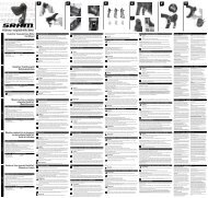
<strong>REVERB</strong> <strong>Remote</strong> <strong>Hose</strong> <strong>Replacement</strong> <strong>and</strong> <strong>System</strong> <strong>Bleed</strong><br />
This service guide covers the steps to replace the Reverb remote hose <strong>and</strong> perform a bleed of the Reverb system.<br />
ImpoRtant:<br />
You must perform a system bleed any time you replace the remote hose.<br />
toolS nEEdEd foR SERVIcE<br />
HoSE REplacEmEnt SYStEm BlEEd<br />
Safety glasses<br />
Nitrile gloves<br />
6 mm open end wrench<br />
Needle nose or slip joint pliers<br />
Sharp utility knife<br />
Cable cutter<br />
High quality hydraulic hose cutter<br />
ImpoRtant:<br />
��SRAM�LLC�������<br />
Safety glasses<br />
Nitrile gloves<br />
Reverb <strong>Bleed</strong> Kit<br />
RockShox�����wt�suspension�luid�<br />
T���<strong>and</strong>�T���Torx�<br />
Torque�wrench�with�a�T���Torx�socket<br />
Clean, lint free rag<br />
do not use avid Hydraulic disc Brake bleed tools or any other bleed kit that speciies dot luid. any dot luid that contaminates the Reverb system will damage the product. In<br />
addition, suspension luid will damage any dot speciic brake bleed tools.<br />
HoSE REplacEmEnt<br />
When replacing the remote hose, you will need to determine the final length of the hose prior to installing it. Determine where you need to cut the new remote hose by routing it<br />
from the remote assembly to the seatpost while the seatpost is in the fully extended position. Make sure to leave a gentle bend at both the remote <strong>and</strong> the seatpost <strong>and</strong> account for<br />
h<strong>and</strong>lebar rotation.<br />
If you are unable to extend the seatpost to its full height, use the old hose length as a guide to determine the new hose length.<br />
1.<br />
c<br />
Push the remote actuator to extend the seatpost to its full height.<br />
��� Clamp the bicycle into a bike st<strong>and</strong>.<br />
B<br />
To clamp a Reverb equipped bicycle into a bike st<strong>and</strong>, loosen the seatpost binder bolt/quick release at the frame. Raise<br />
the seatpost to the Minimum Insertion line then tighten the seatpost binder bolt/quick release to the frame manufacturer’s<br />
recommendation. Do not exceed 6.7 N·m (60 in-lb).<br />
Important: clamp the seatpost into the bike st<strong>and</strong> just below the top cap. do not clamp the seatpost by the top<br />
cap or allow the hose to be clamped as this may damage the seatpost.<br />
3. Turn the speed adjuster on the remote counter-clockwise to the Full Slow position (this is opposite the direction of the<br />
arrow printed on the speed adjuster).<br />
4. Orient the bike so that the remote assembly is higher than the top of the saddle.<br />
��� Use�a�T���Torx�to�loosen�the�remote�clamp�bolt�then�rotate�the�remote�assembly�so�that�the�bleed�screw�is�at�the�highest�point�on�the�remote�<br />
Re-tighten the clamp bolt just enough to prevent the remote assembly from rotating on the h<strong>and</strong>lebar.<br />
6. Place�an�oil�pan�on�the�loor�directly�beneath�the�remote�assembly�<br />
f<br />
E<br />
A - <strong>Remote</strong> hose<br />
B - Minimum insertion line<br />
C - Top Cap<br />
7. Use a cable cutter to cut the remote hose approximately 1" (one inch) from the remote assembly.<br />
Allow any oil to drain into the oil pan.<br />
a<br />
t10<br />
d<br />
G<br />
D - <strong>Remote</strong> assembly<br />
E - Actuator<br />
F - Speed adjuster<br />
G - <strong>Bleed</strong> port/bleed screw<br />
t25<br />
<strong>Remote</strong> Clamp Bolt<br />
����N∙m��������in�lb�<br />
1
8. Move the oil pan underneath the seatpost.<br />
9. Use a cable cutter to cut the remote hose approximately 1" (one inch) from the strain relief at the seatpost.<br />
Allow any oil to drain into the oil pan.<br />
Discard the old remote hose.<br />
����Use<br />
a 6 mm open end wrench to unthread the hose barbs at both the remote assembly <strong>and</strong> seatpost. Discard the old hose barbs.<br />
Important: do not reuse the old hose or hose barbs.<br />
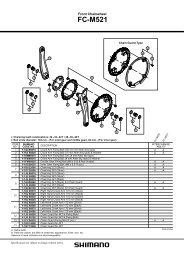
11. Thread the new, longer hose barb, by h<strong>and</strong>, into the remote assembly. Ensure the o-ring is present on the hose barb prior to installing it.<br />
Use a torque wrench with a 6 mm socket to tighten the remote assembly barb to 3.1 N∙m�����in�lb��<br />
����Thread<br />
the new, shorter hose barb, by h<strong>and</strong>, into the seatpost. Ensure the o-ring is present on the hose barb prior to installing it. Use a torque wrench with a 6 mm socket to<br />
tighten�the�seatpost�barb�to�����N∙m�����in�lb��<br />
13. Use a hydraulic hose cutter to cut the new hose to the desired length.<br />
14. Grip one end of the remote hose with a pair of pliers. do not damage the remote hose by gripping it too tightly. Use a twisting motion to press the remote hose back onto the<br />
seatpost hose barb. Continue to press the remote hose onto the hose barb until the end of the hose makes contact with the base of the barb.<br />
����Slide the strain relief, large end first, over the length of the remote hose. Press the strain relief onto the seatpost hose barb. Make sure the Reverb logo, embossed on the strain<br />
relief, is visible from the non-drive side of the seatpost.<br />
16. Grip the other end of the remote hose with a pair of pliers. do not damage the remote hose by gripping it too tightly. Use a twisting motion to press the remote hose back onto<br />
the remote assembly hose barb. Continue to press the remote hose onto the hose barb until the end of the hose makes contact with the base of the barb.<br />
You have completed the <strong>Remote</strong> <strong>Hose</strong> <strong>Replacement</strong> portion of this service guide. You will now need to perform a <strong>System</strong> <strong>Bleed</strong> in order for your seatpost to function properly.<br />
SYStEm BlEEd<br />
1. Confirm the system is prepared according to steps 1-6 of the <strong>Remote</strong> <strong>Hose</strong> <strong>Replacement</strong> instructions.<br />
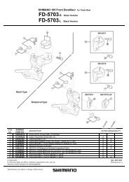
��� Use�a�T���Torx�to�remove�the�both�the�seatpost�<strong>and</strong>�remote�assembly�bleed�screws�<br />
Note the diference in shape between the two bleed screws so you don't confuse them later. The seatpost bleed screw has a lat base <strong>and</strong> o-ring, while the remote assembly bleed<br />
screw has a pointed base.<br />
Set the bleed screws aside.<br />
3. Prepare�the�irst�RockShox�Reverb�bleed�syringe�by�illing�it���full�of�RockShox����wt�oil��<br />
Hold the syringe with the tip pointed up.<br />
Place a rag around the tip <strong>and</strong> slowly push any air bubbles out of the syringe.<br />
4. Thread the syringe into the remote assembly bleed port.<br />
��� Prepare the second, empty, RockShox Reverb bleed syringe by pushing the syringe plunger all the way in, then thread the empty syringe into the seatpost bleed port.<br />
6. Purge the system of air <strong>and</strong> fill it with oil.<br />
7.<br />
While holding both syringes upright, gently push on the remote assembly syringe plunger <strong>and</strong> gently pull up on the seatpost syringe plunger at the same time. This will force oil<br />
<strong>and</strong> any air bubbles through the remote assembly, remote hose, seatpost, <strong>and</strong> into the seatpost syringe.<br />
Continue to push on the remote assembly syringe plunger until it is nearly empty.<br />
Important: at this point, an excessive amount of air may accumulate in the seatpost syringe which can make the bleed process diicult. If this occurs, unthread the seatpost<br />
syringe from the bleed port, hold the syringe with the tip pointed up, place a rag around the tip <strong>and</strong> slowly push any air out of the syringe. thread the syringe back into the<br />
seatpost bleed port.<br />
<strong>Bleed</strong> any remaining air from the system.<br />
While holding both syringes upright, gently push on the seatpost syringe plunger until the syringe is nearly empty <strong>and</strong> pull up on the remote syringe at the same time. You should<br />
see air bubbles <strong>and</strong> oil moving into the remote syringe.<br />
Then, gently push on the remote assembly syringe plunger until the syringe is nearly empty <strong>and</strong> pull up on the seatpost syringe at the same time. You may see air bubbles in the<br />
oil as oil fills the seatpost syringe.<br />
Cycle the oil between the seatpost <strong>and</strong> remote assembly syringes, by pushing <strong>and</strong> pulling, until no more air bubbles transfer into either syringe.<br />
Finish the process of cycling the oil between the seatpost <strong>and</strong> remote assembly with a firm push on the seatpost syringe plunger until the syringe is nearly empty <strong>and</strong> pulling up<br />
on the remote syringe at the same time.<br />
8. Unthread the syringe from the seatpost bleed port.<br />
9. Use�a�T���Torx�to�thread�the�seatpost�bleed�screw��the�bleed�screw�with�the�lat�base�<strong>and</strong>�o�ring��into�the�seatpost�bleed�port�<strong>and</strong>�tighten�it�to�����N∙m�����in�lb��<br />
����Dislodge<br />
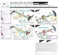
any remaining bubbles from inside the remote assembly.<br />
While pushing on the remote assembly syringe plunger, press the remote actuator 8 times then turn the speed adjuster back <strong>and</strong> forth 4 times.<br />
Pull up on the syringe plunger to remove any air bubbles that may have been dislodged from the remote assembly. Repeat until no more air bubbles come out of the remote<br />
assembly.<br />
11. Complete the bleed process by pushing the remote assembly syringe plunger one final time to force the remote actuator to return to the fully extended position.<br />
Continue to push on the syringe plunger <strong>and</strong> turn the speed adjuster on the remote counter-clockwise to the Full Slow position (this is opposite the direction of the arrow printed<br />
on the speed adjuster).<br />
����Unthread<br />
the syringe from the remote assembly.<br />
13. Use�a�T���Torx�to�thread�the�remote�assembly�bleed�screw��the�bleed�screw�with�the�pointed�base��into�the�seatpost�bleed�port�<strong>and</strong>�tighten�it�to�����N∙m�����in�lb��<br />
14. Use�a�T���Torx�to�loosen�the�remote�clamp�bolt���Rotate�the�remote�to�the�desired�position�on�the�h<strong>and</strong>lebar���Tighten�the�remote�clamp�bolt�to�����N�m��������in�lb��<br />
����Turn<br />
the speed adjuster to the desired setting.<br />
16. Secure the remote hose to the bicycle frame.<br />
17. Spray isopropyl alcohol on the remote assembly, remote hose, <strong>and</strong> seatpost <strong>and</strong> clean them with a lint free rag.<br />
18. Remove the bicycle from the bike st<strong>and</strong>.<br />
19. Set the seatpost to the desired height then tighten the seatpost binder bolt/quick release to the frame manufacturer’s recommendation. do not exceed 6.7 n∙m (60 in-lb).<br />
this completes the Reverb <strong>Remote</strong> Assembly <strong>Hose</strong> <strong>Replacement</strong> <strong>and</strong> <strong>System</strong> <strong>Bleed</strong>.<br />
for additional service information, please visit the service section of our website at www.sram.com.<br />
� ����������������Rev�A�
Reverb Height Adjust Seatpost<br />
User Manual<br />
PLEASE READ THE SAFETY AND WARRANTY INFORMATION INSIDE<br />
95-4215-000-000 Rev. B Copyright © 2010 SRAM, LLC
English Reverb User Manual<br />
2<br />
IMPORTANT<br />
To ensure that your seatpost performs properly <strong>and</strong> to help make your riding experience more<br />
enjoyable <strong>and</strong> trouble-free, we highly recommend that you have it installed by a qualified<br />
bicycle mechanic. We also highly recommend wearing your safety glasses every time you<br />
install <strong>and</strong>/or service your bicycle components.<br />
Important: DO NOT attempt to adjust air pressure using the air valve located at the bottom<br />
of the seatpost. Any change in the factory air pressure setting will render the seatpost<br />
inoperable, requiring full service.<br />
COMPATIBILITY<br />
• RockShox seatposts are compatible with saddles with 7 mm rail diameters <strong>and</strong> are<br />
designed for use with 30.9 mm <strong>and</strong> 31.6 mm seat tube internal diameters.<br />
• Seatpost <strong>and</strong> seat tube diameters must be the same. RockShox seatpost diameters are<br />
printed on the products.<br />
Important: Do not use a reduction sleeve to alter the seat tube diameter.<br />
TOOLS NEEDED<br />
• Safety glasses<br />
• 4 mm hex wrench<br />
• T25 TORX®<br />
wrench<br />
• Torque wrench<br />
• Friction paste<br />
• Isopropyl alcohol<br />
• Clean, lint free rag<br />
95-4215-000-000 Rev B<br />
Reverb User Manual<br />
B C B<br />
D<br />
E<br />
A - Saddle clamp bolts (2)<br />
B - Saddle clamp nuts (2)<br />
C - Top clamp<br />
D - Bottom clamp<br />
E - Minimum insertion line<br />
IDENTIFY PARTS<br />
English<br />
Copyright © 2010 SRAM, LLC 3<br />
A<br />
J<br />
F<br />
G<br />
I<br />
A<br />
F - <strong>Remote</strong> hose<br />
G - Strain relief boot<br />
H - <strong>Remote</strong> assembly<br />
I - Actuator<br />
J - Speed adjuster<br />
H
English Reverb User Manual<br />
4<br />
1<br />
2<br />
3<br />
PREPARE THE FRAME<br />
Use isopropyl alcohol <strong>and</strong> a clean, lint free rag to clean any debris or grease from the<br />
inside of the seat tube. Remove any burrs from frame’s seat tube edges then smooth<br />
with 400 grit s<strong>and</strong>paper.<br />
PREPARE THE SEATPOST<br />
Remove the saddle clamp bolt(s) <strong>and</strong> apply grease to the bolt threads. Loosely<br />
re-install the saddle clamp bolts.<br />
APPLY FRICTION PASTE<br />
Apply a moderate amount of friction paste to the inside of the seat tube <strong>and</strong> contact<br />
surface of the seatpost. Do not apply grease.<br />
WARNING - Seatpost Slippage<br />
Friction paste is designed to create friction between the contact surfaces to prevent<br />
the seatpost from slipping without over-torquing the seat clamp device. Failure to use<br />
friction paste could allow your seatpost to slip during use which could lead to serious<br />
injury <strong>and</strong>/or death.<br />
95-4215-000-000 Rev B<br />
Reverb User Manual<br />
4<br />
5<br />
INSTALL THE SEATPOST<br />
Your seatpost must be inserted into the seat tube a minimum<br />
of 80 mm or the minimum amount specified by your frame<br />
manufacturer; whichever is greater. Torque the seat<br />
clamp device to the frame manufacturer’s lowest<br />
specification. Do not exceed 6.7 N·m (60 in-lb).<br />
WARNING - Minimum Insertion<br />
You must install your seatpost so that the minimum<br />
required seatpost length is inside the frame’s seat<br />
tube. Installing the seatpost with less than the<br />
minimum length required for insertion can cause<br />
damage to the seatpost <strong>and</strong>/or bicycle frame which can<br />
cause the seatpost <strong>and</strong>/or bicycle frame to fail, which can<br />
lead to serious injury <strong>and</strong>/or death.<br />
IMPORTANT - Strain Relief Clearance<br />
To prevent interference when the seatpost is adjusted<br />
to its lowest position, rotate the strain relief boot so that<br />
the <strong>REVERB</strong> logo faces out.<br />
INSTALL THE SADDLE TO THE SEATPOST<br />
Make sure the saddle rails are seated in the<br />
grooves between the top <strong>and</strong> bottom clamps.<br />
NOTE - The top clamp does not need to be<br />
completely removed to install the saddle.<br />
≥80 mm<br />
≤6.7 N·m<br />
(≤60 in-lb)<br />
English<br />
Copyright © 2010 SRAM, LLC 5
English Reverb User Manual<br />
6<br />
6<br />
7<br />
8<br />
ADJUST THE SADDLE ANGLE<br />
Adjust your saddle to the angle <strong>and</strong> fore-aft position of your preference, then use a<br />
4 mm hex to tighten each seat clamp bolt, in an alternating fashion, to<br />
8-10 N·m (70-89 in-lb).<br />
4<br />
8-10 N·m<br />
(70-89 in-lb)<br />
ALIGN THE SEATPOST TO THE FRAME<br />
If necessary, loosen the seat clamp device on your frame <strong>and</strong><br />
align your seatpost so that the saddle is in line with the top<br />
tube of your frame. Re-torque the seat clamp device to the<br />
frame manufacturer’s specifications or 5-6 N·m (40-60 in-lb),<br />
whichever is lower.<br />
INSTALL THE REMOTE (DISCRETE CLAMP)<br />
4<br />
8-10 N·m<br />
(70-89 in-lb)<br />
Close the remote clamp around the h<strong>and</strong>lebar. Insert the remote clamp bolt <strong>and</strong> use<br />
a T25 TORX ® to loosely tighten the bolt to hold the assembly together. Rotate the<br />
remote clamp to the desired position <strong>and</strong> tighten the clamp bolt to<br />
5-6 N·m (43-52 in-lb).<br />
95-4215-000-000 Rev B<br />
Reverb User Manual<br />
INSTALL THE REMOTE (MATCHMAKER X)<br />
<strong>Remote</strong> - Install the remote bracket nut in the channel<br />
on the inside surface of the remote clamp. Position<br />
the remote bracket on the outside of the<br />
MatchMaker X (MMX) clamp <strong>and</strong> install the MMX<br />
bracket bolt. Use a T25 TORX® to torque the bracket<br />
bolt to 3-4 N·m (35-44 in-lb).<br />
Brake lever - Position the brake lever against the<br />
h<strong>and</strong>lebar. Close the remote clamp around the<br />
h<strong>and</strong>lebar <strong>and</strong> brake lever. Insert the remote clamp<br />
bolt <strong>and</strong> loosely tighten the bolt to hold the assembly<br />
together. Rotate the remote clamp to the desired<br />
position <strong>and</strong> use a T25 TORX to tighten the clamp bolt<br />
to 5-6 N·m (43-52 in-lb).<br />
Shifter - Attach the shifter to the remote bracket with<br />
the shifter mounting bolt. Use a T25 TORX wrench to<br />
torque the shifter mounting bolt to<br />
2.8-3.4 N∙m (25-30 in-lb). Reposition the shifter if<br />
necessary by loosening the MMX bracket bolt,<br />
adjusting the angle of the shifter, <strong>and</strong> re-tightening the<br />
bracket bolt to 3-4 N·m (35-44 in-lb).<br />
English<br />
Copyright © 2010 SRAM, LLC 7<br />
25<br />
25<br />
5-6 N·m<br />
(43-52 in-lb)<br />
2.8 - 3.4 N·m<br />
(25-30 in-lb)<br />
25<br />
3-4 N·m<br />
(35-44 in-lb)
English Reverb User Manual<br />
8<br />
9<br />
10<br />
RAISE AND LOWER THE SADDLE<br />
Before riding your bike, sit on your bike while it is stationary <strong>and</strong> cycle the seatpost<br />
through its travel a couple of times. To lower the seatpost completely, press <strong>and</strong> hold<br />
the actuator; your body weight will compress the seatpost. To raise the seatpost,<br />
unweight the saddle then press <strong>and</strong> release the actuator.<br />
You can adjust the height of the seatpost to any point in its travel by releasing the<br />
actuator while the seatpost is at the desired height.<br />
NOTE - It is possible to manually raise the seatpost without actuating the remote by<br />
pulling up on the saddle with enough force.<br />
ADJUST THE SPEED OF THE SEATPOST<br />
Turn the speed adjuster on the remote counter-clockwise<br />
to decrease the speed of the saddle height change or<br />
clockwise to increase the speed of the saddle height<br />
change.<br />
95-4215-000-000 Rev B<br />
Reverb User Manual<br />
11<br />
SAFETY CHECK<br />
Check that the seatpost does not slip in the frame. Check that the saddle does not slip<br />
on the seatpost clamp.<br />
MAINTENANCE<br />
When the post sits for a prolonged period of time without movement, it may develop a slight<br />
increase in breakaway friction. This is normal <strong>and</strong> will cease once the seatpost is cycled.<br />
If the breakaway is excessive or does not cease once seatpost is cycled, cleaning <strong>and</strong><br />
lubrication of the seatpost may be required.<br />
English<br />
Copyright © 2010 SRAM, LLC 9
English Reverb User Manual<br />
10<br />
SRAM LLC WARRANTY<br />
EXTENT OF LIMITED WARRANTY<br />
SRAM warrants its products to be free from defects in materials<br />
or workmanship for a period of two years after original purchase.<br />
This warranty only applies to the original owner <strong>and</strong> is not<br />
transferable. Claims under this warranty must be made through<br />
the retailer where the bicycle or the SRAM component was<br />
purchased. Original proof of purchase is required.<br />
LOCAL LAW<br />
This warranty statement gives the customer specific legal<br />
rights. The customer may also have other rights which vary from<br />
state to state (USA), from province to province (Canada), <strong>and</strong><br />
from country to country elsewhere in the world.<br />
To the extent that this warranty statement is inconsistent<br />
with the local law, this warranty shall be deemed modified<br />
to be consistent with such law, under such local law, certain<br />
disclaimers <strong>and</strong> limitations of this warranty statement may apply<br />
to the customer. For example, some states in the United States<br />
of America, as well as some governments outside of the United<br />
States (including provinces in Canada) may:<br />
a. Preclude the disclaimers <strong>and</strong> limitations of this warranty<br />
statement from limiting the statutory rights of the consumer (e.g.<br />
United Kingdom).<br />
b. Otherwise restrict the ability of a manufacturer to enforce<br />
such disclaimers or limitations.<br />
LIMITATIONS OF LIABILITY<br />
To the extent allowed by local law, except for the obligations<br />
specifically set forth in this warranty statement, In no event<br />
shall SRAM or its third-party suppliers be liable for direct,<br />
indirect, special, incidental, or consequential damages.<br />
LIMITATIONS OF WARRANTY<br />
· This warranty does not apply to products that have been<br />
incorrectly installed <strong>and</strong>/or adjusted according to the respective<br />
SRAM technical installation manual. The SRAM installation<br />
manuals can be found online at www.sram.com, www.rockshox.<br />
com, www.avidbike.com, www.truvativ.com, or www.zipp.com.<br />
TORX ® is a registered trademark of Acument Intellectual Properties, LLC<br />
· This warranty does not apply when the product has been<br />
modified.<br />
· This warranty does not apply when the serial number or<br />
production code has been deliberately altered, defaced or<br />
removed.<br />
· This warranty does not apply to damage to the product<br />
caused by a crash, impact, abuse of the product, noncompliance<br />
with manufacturer’s specifications of usage<br />
or any other circumstances in which the product has been<br />
subjected to forces or loads beyond its design.<br />
· This warranty does not apply to normal wear <strong>and</strong> tear. Wear<br />
<strong>and</strong> tear parts are subject to damage as a result of normal<br />
use, failure to service according to SRAM recommendations<br />
<strong>and</strong>/or riding or installation in conditions or applications<br />
other than recommended.<br />
WEAR AND TEAR PARTS ARE IDENTIFIED AS:<br />
Dust seals/Bushings/Air sealing o-rings/Glide rings/Rubber<br />
moving parts/Foam rings/Rear shock mounting hardware <strong>and</strong><br />
main seals/Stripped threads <strong>and</strong> bolts (aluminum,titanium,<br />
magnesium or steel)/Upper tubes (stanchions)/Brake<br />
sleeves/Brake pads/Chains/Sprockets/Cassettes/Shifter<br />
<strong>and</strong> brake cables (inner <strong>and</strong> outer)/H<strong>and</strong>lebar grips/Shifter<br />
grips/Jockey wheels/Disc brake rotors/Wheel braking<br />
surfaces/Bottom out pads/Bearings/Bearing races/Pawls/<br />
Transmission gears/Spokes/Free hubs/Aero bar pads/<br />
Corrosion/Tools<br />
· This warranty shall not cover damages caused by the use of<br />
parts of different manufacturers.<br />
· This warranty shall not cover damages caused by the use of<br />
parts that are not compatible, suitable <strong>and</strong>/or authorized by<br />
SRAM for use with SRAM components.<br />
· This warranty shall not cover damages resulting from<br />
commercial (rental) use.<br />
95-4215-000-000 Rev B<br />
Reverb höhenverstellbare Sattelstütze<br />
Bedienungsanleitung<br />
BITTE BEACHTEN SIE DIE INNENSEITIGEN SICHERHEITS- UND GARANTIEINFORMATIONEN<br />
95-4215-000-000 Rev. A Copyright © 2010 SRAM, LLC
Deutsch Reverb Bedienungsanleitung<br />
12<br />
WICHTIG<br />
Um die ordnungsgemäße Funktion Ihrer Sattelstütze sicherzustellen und ein optimales<br />
Fahrerlebnis zu gewährleisten, wird dringend empfohlen, den Einbau von einem qualifizierten<br />
Fahrradmechaniker vornehmen zu lassen. Wir empfehlen Ihnen außerdem, bei der<br />
Installation und/oder Wartung von Fahrradkomponenten eine Schutzbrille zu tragen.<br />
Wichtig: Versuchen Sie NICHT, den Luftdruck über das Luftventil am unteren Ende der<br />
Sattelstütze einzustellen. Jegliche Änderung des werkseitig voreingestellten Luftdrucks<br />
macht die Sattelstütze unbrauchbar, sodass eine Komplettwartung erforderlich ist.<br />
KOMPATIBILITÄT<br />
• RockShox -Sattelstützen eignen sich für Sättel mit einem Schienendurchmesser von 7 mm<br />
und sind für Sattelrohre mit einem Innendurchmesser von 30,9 mm oder 31,6 mm ausgelegt.<br />
• Der Sattelstützen- und Sattelrohrdurchmesser müssen übereinstimmen. Die<br />
Sattelstützendurchmesser sind auf den RockShox-Produkten aufgedruckt.<br />
Wichtig: Verwenden Sie keine Reduzierhülsen, um den Durchmesser des Sattelrohrs zu<br />
verändern.<br />
ERFORDERLICHES WERKZEUG<br />
• Augenschutz<br />
• 4-mm-Inbusschlüssel<br />
• T25 TORX®-Schlüssel<br />
• Drehmomentschlüssel<br />
• Friktionspaste<br />
• Isopropyl-Alkohol<br />
• Saubere Lappen (fusselfrei)<br />
95-4215-000-000 Rev B<br />
Reverb Bedienungsanleitung<br />
B C B<br />
D<br />
A - Sattelklemmschrauben (2)<br />
B - Sattelklemmmuttern (2)<br />
C - Obere Klemmung<br />
D - Untere Klemmung<br />
E - Markierung für minimale Einstecktiefe<br />
E<br />
BAUTEILE<br />
Deutsch<br />
Copyright © 2010 SRAM, LLC 13<br />
A<br />
J<br />
F<br />
G<br />
I<br />
A<br />
H<br />
F - Fernbedienungsschlauch<br />
G - Zugentlastungsmanschette<br />
H - Fernbedienungsbaugruppe<br />
I - Einsteller<br />
J - Geschwindigkeitseinsteller
Deutsch Reverb Bedienungsanleitung<br />
14<br />
1<br />
2<br />
3<br />
RAHMEN VORBEREITEN<br />
Reinigen Sie die Innenseite des Sattelrohrs mit Isopropyl-Alkohol und einem<br />
sauberen, fusselfreien Lappen. Entfernen Sie jegliche Grate von den Rändern des<br />
Sattelrohrs mit Schleifpapier (Körnung 400).<br />
SATTELSTÜTZE VORBEREITEN<br />
Entfernen Sie die Sattelklemmschraube(n), und tragen Sie Fett auf die Gewinde der<br />
Schrauben auf. Bringen Sie die Sattelklemmschraube(n) lose wieder an.<br />
FRIKTIONSPASTE AUFTRAGEN<br />
Tragen Sie vor der Montage auf die Innenseiten des Sattelrohrs und die Kontaktfläche<br />
der Sattelstütze ein wenig Friktionspaste auf. Die Teile nicht fetten.<br />
WARNUNG - Durchrutschen der Sattelstütze<br />
Friktionspaste ist dafür vorgesehen, Reibung zwischen den Kontaktflächen zu<br />
erzeugen, damit die Sattelstütze nicht aus der Klemmung rutschen kann, ohne dass<br />
Sie die Sattelklemmschrauben zu fest anzuziehen müssen. Wenn Sie keine<br />
Friktionspaste verwenden, kann die Sattelstütze während der Fahrt in den Rahmen<br />
rutschen, was zu schweren und/oder tödlichen Verletzungen führen kann.<br />
95-4215-000-000 Rev B<br />
Reverb Bedienungsanleitung<br />
4<br />
5<br />
SATTELSTÜTZE MONTIEREN<br />
Die Sattelstütze muss mindestens 80 mm tief bzw. so<br />
weit wie vom Rahmenhersteller vorgeschrieben in das<br />
Sattelrohr eingeführt werden (je nachdem, welcher<br />
Wert größer ist). Ziehen Sie die Sattelstützen-<br />
Klemmvorrichtung gemäß dem vom Hersteller<br />
vorgegebenen Mindestwert an. Das Anzugsmoment<br />
darf 6,7 N·m nicht übersteigen.<br />
≥80 mm<br />
WARNUNG - Mindesteinstecktiefe<br />
Sie müssen Ihre Sattelstütze so einbauen, dass<br />
sie sich mit der erforderlichen Mindestlänge im<br />
Sattelrohr des Rahmens befindet. Andernfalls kann es<br />
zu Schäden an der Sattelstütze und/oder am Rahmen<br />
kommen, die zum Versagen der Sattelstütze und/ oder<br />
des Rahmens führen können, sodass die Gefahr von<br />
schweren und/ oder tödlichen Verletzungen besteht.<br />
WICHTIG - Abst<strong>and</strong> zur Zugentlastung<br />
Um die störungsfreie Funktion der Zugentlastung bei<br />
maximal eingeführter Sattelstütze zu gewährleisten,<br />
drehen Sie die Zugentlastungsmanschette so, dass das<br />
<strong>REVERB</strong>-Logo nach außen zeigt.<br />
SATTEL AN DER SATTELSTÜTZE MONTIEREN<br />
Stellen Sie sicher, dass die Sattelschienen in den<br />
Führungen zwischen der oberen und unteren<br />
Klemmung sitzen.<br />
HINWEIS - Sie brauchen die obere Klemmung<br />
nicht vollständig auszubauen, um den Sattel zu<br />
montieren.<br />
≤6,7 N·m<br />
Deutsch<br />
Copyright © 2010 SRAM, LLC 15
Deutsch Reverb Bedienungsanleitung<br />
16<br />
6<br />
7<br />
8<br />
WINKEL DES SATTELS EINSTELLEN<br />
Stellen Sie den Sattel im gewünschten Winkel und der gewünschten Position ein, und<br />
ziehen Sie dann die beiden Schrauben mit einem 4-mm-Inbusschlüssel abwechselnd<br />
mit 10 N·m an.<br />
4<br />
8-10 N·m<br />
SATTELSTÜTZE AUF DEN SATTEL AUSRICHTEN<br />
Falls erforderlich, lösen Sie die Sattelklemmvorrichtung an<br />
Ihrem Rahmen und richten Sie die Sattelstütze so aus, dass<br />
sie in einer Linie mit dem Oberrohr des Fahrradrahmens steht.<br />
Ziehen Sie die Sattelklemmvorrichtung erneut gemäß den<br />
Anweisungen des Rahmenherstellers oder mit 5 bis 6 N·m an<br />
(je nachdem, welcher Wert geringer ist).<br />
FERNBEDIENUNG ANBRINGEN (SEPARATE KLEMMUNG)<br />
4<br />
8-10 N·m<br />
Schieben Sie die Fernbedienungsklemmung über den Lenker. Setzen Sie die<br />
Fernbedienungsklemmschraube ein und ziehen Sie sie mit einem<br />
T25 TORX ®-Schlüssel leicht an, um die Baugruppe zusammenzuhalten. Platzieren<br />
Sie die Fernbedienungsklemmung in der gewünschten Position und ziehen Sie die<br />
Klemmschraube mit 5 bis 6 N·m an.<br />
95-4215-000-000 Rev B<br />
Reverb Bedienungsanleitung<br />
FERNBEDIENUNG ANBRINGEN (MATCHMAKER X)<br />
Fernbedienung - Platzieren Sie die Mutter der<br />
Fernbedienungsklemmung in der Vertiefung auf der<br />
Innenseite der Fernbedienungsklemmung. Platzieren<br />
Sie die Fernbedienungsklemmung außen neben<br />
der MatchMaker X (MMX)-Klemmung und bringen<br />
Sie die MMX-Klemmschraube an. Ziehen Sie die<br />
Klemmschraube mit einem T25 TORX ®-Schlüssel mit<br />
3 bis 4 N·m an.<br />
Bremshebel - Platzieren Sie den Bremshebel am<br />
Lenker. Schließen Sie die Fernbedienungsklemmung<br />
um den Lenker und den Bremshebel. Setzen Sie die<br />
Fernbedienungsklemmschraube ein und ziehen Sie<br />
sie leicht an, um die Baugruppe zusammenzuhalten.<br />
Drehen Sie die Fernbedienungsklemmung in<br />
die gewünschte Position und ziehen Sie die<br />
Klemmschraube mit einem T25 TORX-Schlüssel mit 5<br />
bis 6 N·m an.<br />
Schalthebel - Fixieren Sie den Schalthebel<br />
mit der Schalthebel-Befestigungsschraube an<br />
der Fernbedienungsklemmung. Ziehen Sie die<br />
Schalthebel-Befestigungsschraube mit einem<br />
T25 TORX-Schlüssel mit 2,8 bis 3,4 N·m an. Ändern<br />
Sie die Position des Schalthebels bei Bedarf, indem<br />
Sie die MMX-Klemmschraube lösen, den Winkel des<br />
Schalthebels anpassen und dann die Klemmschraube<br />
mit 3 bis 4 N·m wieder festziehen.<br />
25 5-6 N·m<br />
25 2,8-3,4 N·m<br />
Deutsch<br />
Copyright © 2010 SRAM, LLC 17<br />
25<br />
3-4 N·m
Deutsch Reverb Bedienungsanleitung<br />
18<br />
9<br />
10<br />
SATTEL HÖHER ODER NIEDRIGER STELLEN<br />
Bevor Sie mit dem Fahrrad fahren, setzen Sie sich auf das Fahrrad und bewegen Sie<br />
die Sattelstütze einige Male vollständig durch ihren gesamten Einstellweg. Um die<br />
Sattelstütze vollständig nach unten zu stellen, drücken und halten Sie den Einsteller<br />
gedrückt, sodass die Sattelstütze durch Ihr Körpergewicht zusammengedrückt<br />
wird. Um die Sattelstütze höher zu stellen, entlasten Sie den Sattel, drücken Sie den<br />
Einsteller und lassen Sie ihn wieder los.<br />
Sie können die Sattelstütze auf eine beliebige Höhe nach unten stellen, indem Sie<br />
den Einsteller auf der gewünschten Höhe loslassen.<br />
HINWEIS - Sie können die Sattelstütze von H<strong>and</strong> nach oben stellen, ohne die<br />
Fernbedienung zu betätigen, indem Sie den Sattel mit ausreichend Kraft nach oben<br />
ziehen.<br />
GESCHWINDIGKEIT DER SATTELSTÜTZE EINSTELLEN<br />
Drehen Sie den Geschwindigkeitseinsteller an der<br />
Fernbedienung gegen den Uhrzeigersinn, um die<br />
Geschwindigkeit der Sattelhöhenverstellung zu<br />
verringern bzw. drehen Sie ihn im Uhrzeigersinn, um die<br />
Geschwindigkeit der Sattelhöhenverstellung zu erhöhen.<br />
95-4215-000-000 Rev B<br />
Reverb Bedienungsanleitung<br />
11 SICHERHEITSPRÜFUNG<br />
Stellen Sie sicher, dass die Sattelstütze im Rahmen nicht rutscht. Stellen Sie sicher,<br />
dass der Sattel in der Sattelstützenklemmung nicht rutscht.<br />
WARTUNG<br />
Wenn die Sattelstütze längere Zeit nicht bewegt wird, nimmt die Reibung möglicherweise<br />
etwas zu. Das ist normal und gibt sich, wenn die Sattelstütze einige Male durchbewegt<br />
wird.<br />
Wenn die Reibung übermäßig ist oder nach dem Durchbewegen der Sattelstütze nicht<br />
nachlässt, muss die Sattelstütze möglicherweise gereinigt und geschmiert werden.<br />
Deutsch<br />
Copyright © 2010 SRAM, LLC 19
Deutsch Reverb Bedienungsanleitung<br />
GARANTIEUMFANG<br />
SRAM garantiert vom Erstkaufdatum an für zwei Jahre, dass<br />
das Produkt frei von Mängeln in Material oder Verarbeitung ist.<br />
Diese Gewährleistung kann nur vom Erstkäufer in Anspruch<br />
genommen werden und ist nicht übertragbar. Ansprüche aus dieser<br />
Gewährleistung sind über den Händler, bei dem das Fahrrad oder<br />
die SRAM-Komponente erworben wurde, geltend zu machen. Der<br />
Kaufbeleg muss im Original vorgelegt werden.<br />
20<br />
GEWÄHRLEISTUNG DER SRAM LLC<br />
LOKALE GESETZGEBUNG<br />
Diese Gewährleistung räumt Ihnen spezifische Rechte ein. Je nach<br />
Bundesl<strong>and</strong> (USA), Provinz (Kanada) oder Ihrem Wohnl<strong>and</strong> verfügen<br />
Sie möglicherweise über weitere Rechte.<br />
Die Gewährleistung ist in dem Maße, in dem sie von der lokalen<br />
Gesetzgebung abweicht, in Übereinstimmung mit der geltenden<br />
Gesetzgebung zu bringen. Der jeweiligen lokalen Gesetzgebung<br />
unterliegen möglicherweise Ausschlüsse und Einschränkungen<br />
aus dieser Gewährleistung. Für bestimmte Bundesstaaten der<br />
USA sowie einige Länder außerhalb der USA (einschließlich von<br />
Kanadischen Provinzen) gilt beispielsweise Folgendes:<br />
a. Die Ausschlüsse und Einschränkungen in dieser Gewährleistung<br />
dürfen die gesetzlich festgelegten Rechte des Verbrauchers nicht<br />
beeinträchtigen (z.B. Großbritannien).<br />
b. Andernfalls sind derartige Ausschlüsse und Einschränkungen<br />
unwirksam.<br />
HAFTUNGSBESCHRÄNKUNG<br />
Im nach der örtlichen Gesetzgebung zulässigen Maße und mit<br />
Ausnahme der in der vorliegenden Gewährleistung ausdrücklich<br />
dargelegten Verpflichtungen schließen SRAM bzw. seine<br />
Lieferanten jegliche Haftung für direkte, indirekte, spezielle,<br />
zufällige oder Folgeschäden aus.<br />
GEWÄHRLEISTUNGSAUSSCHLUSS<br />
· Die Garantie gilt nicht für Produkte, die nicht fachgerecht bzw.<br />
nicht gemäß den Montageanleitungen von SRAM montiert und/oder<br />
eingestellt wurden. Die SRAM-Montageanleitungen finden Sie im<br />
Internet unter www.sram.com, www.rockshox.com,<br />
www.avidbike.com, www.truvativ.com oder www.zipp.com.<br />
· Bei Veränderungen am Produkt erlischt der<br />
Gewährleistungsanspruch.<br />
· Der Gewährleistungsanspruch erlischt ebenfalls, wenn die<br />
Seriennummer bzw. der Herstellungscode verändert, unkenntlich<br />
gemacht oder entfernt wurde.<br />
· Diese Garantie gilt nicht bei Schäden am Produkt<br />
infolge von Unfällen, Stürzen oder missbräuchlicher<br />
Nutzung, Nichtbeachtung der Herstellerangaben oder<br />
sonstigen Umständen, unter denen das Produkt nicht<br />
bestimmungsgemäßen Belastungen oder Kräften ausgesetzt<br />
wurde.<br />
· Normaler Verschleiß und Abnutzung sind von der<br />
Gewährleistung ausgeschlossen. Zum normalen Verschleiß von<br />
Komponenten kann es infolge des sachgemäßen Gebrauchs,<br />
der Nichteinhaltung von Wartungsempfehlungen von SRAM<br />
und/oder von Fahren unter <strong>and</strong>eren als den empfohlenen<br />
Bedingungen kommen.<br />
FOLGENDE KOMPONENTEN UNTERLIEGEN DEM „NORMALEN<br />
VERSCHLEISS“:<br />
Staubdichtungen/Buchsen/Luftschließende O-Ringe/<br />
Gleitringe/Bewegliche Teile aus Gummi/Schaumgummiringe/<br />
Federelemente und -Hauptlager am Hinterbau/Obere Rohre<br />
(Tauchrohre)/Überdrehte Gewinde/Schrauben (Aluminium,<br />
Titan, Magnesium oder Stahl)/Bremshebelüberzüge/<br />
Bremsbeläge/Ketten/Kettenräder/Kassetten/Schalt- und<br />
Bremszüge (Innen- und Außenzüge)/Lenkergriffe/Schaltgriffe/<br />
Spannrollen/Bremsscheiben/Bremsflächen der Felgen/<br />
Federanschlagdämpfer/Lager/Lagerlaufflächen/Sperrklinken/<br />
Antriebszahnräder/Speichen/Freilaufnaben/Aerolenker-Polster/<br />
Korrosion/Werkzeug<br />
· Schäden, die von Fremdbauteilen verursacht werden, sind von<br />
der Gewährleistung ausgeschlossen.<br />
· Schäden infolge der Verwendung von Teilen, die nicht<br />
kompatibel oder geeignet sind bzw. nicht von SRAM für die<br />
Verwendung mit SRAM-Komponenten autorisiert wurden, sind<br />
von der Gewährleistung ausgeschlossen.<br />
· Diese Garantie deckt keine Schäden, die infolge gewerblicher<br />
Nutzung (Vermietung) entstehen.<br />
TORX ® ist eine eingetragene Marke der Acument Intellectual Properties, LLC.<br />
95-4215-000-000 Rev B<br />
Manual de la tija de<br />
sillín ajustable en altura Reverb<br />
POR FAVOR, LEA LA INFORMACIÓN SOBRE SEGURIDAD Y GARANTÍA QUE CONTIENE ESTE DOCUMENTO<br />
95-4215-000-000 Rev. A Copyright © 2010 SRAM, LLC
Español Reverb Manual de Usario<br />
22<br />
IMPORTANTE<br />
Para garantizar el correcto funcionamiento de la tija de sillín y ayudarle a que pueda disfrutar<br />
al máximo de su bicicleta sin ningún tipo de problemas, le recomendamos que su instalación<br />
sea realizada por un mecánico de bicicletas cualificado. También le recomendamos<br />
encarecidamente que utilice gafas de seguridad siempre que realice algún trabajo de<br />
instalación y/o mantenimiento de componentes de su bicicleta.<br />
Importante: NO intente ajustar la presión de aire utiliz<strong>and</strong>o la válvula neumática situada en la<br />
parte inferior de la tija de sillín. Cualquier cambio en la presión de aire que viene ajustada de<br />
fábrica dejará fuera de servicio la tija de sillín y obligará a someterla a una revisión completa.<br />
COMPATIBILIDAD<br />
• Las tijas de sillín RockShox son compatibles con sillines con carril de 7 mm de diámetro, y<br />
están diseñadas para su utilización con tubos de sillín con diámetros internos de 30,9 mm<br />
y 31,6 mm.<br />
• Los diámetros de la tija y del tubo de sillín del cuadro deben ser idénticos. Los diámetros<br />
de las tijas RockShox aparecen serigrafiados sobre el propio producto.<br />
Importante: No utilice una vaina reductora para alterar el diámetro del tubo de sillín del<br />
cuadro.<br />
HERRAMIENTAS NECESARIAS<br />
• Gafas de seguridad<br />
• Llave Allen de 4 mm<br />
• Llave T25 TORX®<br />
• Llave dinamométrica<br />
• Pasta de fricción<br />
• Alcohol isopropílico<br />
• Paño limpio que no<br />
desprenda pelusa<br />
95-4215-000-000 Rev B<br />
Reverb Manual de Usario<br />
B C B<br />
D<br />
IDENTIFICACIÓN DE PIEZAS<br />
A - Tornillos de la abrazadera del sillín (2)<br />
B - Tuercas de la abrazadera del sillín (2)<br />
C - Abrazadera superior<br />
D - Abrazadera inferior<br />
E - Línea indicadora de inserción mínima<br />
E<br />
Español<br />
Copyright © 2010 SRAM, LLC 23<br />
A<br />
J<br />
F<br />
G<br />
I<br />
A<br />
H<br />
F - Manguito del control remoto<br />
G - Protector contra tirones<br />
H - Conjunto del control remoto<br />
I - Actuador<br />
J - Ajustador de velocidad
Español Reverb Manual de Usario<br />
24<br />
1<br />
2<br />
3<br />
PREPARACIÓN DEL CUADRO<br />
Limpie con alcohol isopropílico y un paño limpio que no desprenda pelusa la grasa y<br />
suciedad que pueda haber en el interior del tubo de sillín del cuadro. Elimine todas las<br />
rebabas que pueda haber en los extremos del tubo de sillín del cuadro de su bicicleta,<br />
lij<strong>and</strong>o a continuación con lija de arena del 400.<br />
PREPARACIÓN DE LA TIJA DE SILLÍN<br />
Quite los tornillos de la abrazadera del sillín y aplique grasa a las roscas de los<br />
tornillos. Vuelva a colocar los tornillos de la abrazadera del sillín sin llegar a<br />
apretarlos.<br />
APLICACIÓN DE PASTA DE FRICCIÓN<br />
Aplique un poco de pasta de fricción al interior del tubo de sillín del cuadro y a la<br />
superficie de contacto de la tija de sillín. No aplique grasa.<br />
ATENCIÓN - Deslizamiento de la tija de sillín<br />
Esta pasta está diseñada para generar fricción entre las superficies de contacto,<br />
evit<strong>and</strong>o de este modo que la tija resbale, sin necesidad de apretar en exceso los<br />
tornillos de la abrazadera del sillín. Si no utiliza pasta de fricción, la tija podría<br />
resbalar con la bicicleta en marcha y ocasionar lesiones graves o incluso mortales.<br />
95-4215-000-000 Rev B<br />
Reverb Manual de Usario<br />
4<br />
5<br />
INSTALACIÓN DE LA TIJA DE SILLÍN<br />
La tija debe insertarse en el tubo de sillín del cuadro un<br />
mínimo de 80 mm, o bien la longitud mínima especificada<br />
por el fabricante del cuadro (la mayor de ambas cifras).<br />
Apriete el dispositivo de abrazadera de la tija de sillín<br />
con la fuerza mínima especificada por el fabricante.<br />
No sobrepase los 6,7 N·m.<br />
≥80 mm<br />
ATENCIÓN - Inserción mínima<br />
Es fundamental instalar la tija de sillín respet<strong>and</strong>o<br />
el requisito de longitud mínima de inserción de la<br />
tija dentro del tubo de sillín del cuadro. Instalar la<br />
tija de sillín con una longitud de inserción menor que la<br />
especificada puede provocar daños y averías en la tija y/o<br />
en el cuadro de la bicicleta y ocasionar lesiones graves<br />
o incluso mortales.<br />
IMPORTANTE - Separación del protector contra tirones<br />
Para evitar que estorbe cu<strong>and</strong>o la tija de sillín esté<br />
ajustada en la posición más baja, gire el protector<br />
contra tirones de modo que el logotipo <strong>REVERB</strong> quede<br />
apunt<strong>and</strong>o hacia fuera.<br />
INSTALACIÓN DEL SILLÍN EN LA TIJA<br />
Asegúrese de que los carriles del sillín queden<br />
asentados sobre las ranuras situadas entre las<br />
abrazaderas superior e inferior.<br />
NOTA - Para instalar el sillín no es necesario<br />
quitar del todo la abrazadera superior.<br />
≤6,7 N·m<br />
Español<br />
Copyright © 2010 SRAM, LLC 25
Español Reverb Manual de Usario<br />
26<br />
6<br />
7<br />
8<br />
AJUSTE DEL ÁNGULO DEL SILLÍN<br />
Ajuste el sillín con la inclinación longitudinal que prefiera, y a continuación utilice una<br />
llave Allen de 4 mm para apretar de forma alternada cada uno de los tornillos de la<br />
abrazadera de la tija, hasta un par de 10 N·m.<br />
4<br />
8-10 N·m<br />
ALINEACIÓN DE LA TIJA DE SILLÍN CON RESPECTO AL<br />
CUADRO<br />
Si es necesario, afloje el dispositivo de abrazadera del<br />
sillín y alinee la tija de modo que el sillín quede paralelo al<br />
tubo superior del cuadro. Vuelva a apretar el dispositivo<br />
de abrazadera del sillín con un par de entre 5 y 7 N·m, o la<br />
cantidad especificada por el fabricante (la menor de ambas<br />
cifras).<br />
INSTALACIÓN DEL CONTROL REMOTO (ABRAZADERA SUELTA)<br />
4<br />
8-10 N·m<br />
Cierre la abrazadera del control remoto alrededor del manillar. Inserte el tornillo de<br />
la abrazadera del control remoto y utilice una llave T25 TORX ® para apretar un poco<br />
el tornillo, justo lo suficiente para mantener sujeto el conjunto. Gire la abrazadera del<br />
control remoto hasta la posición deseada y apriete el tornillo con un par de entre<br />
5 y 6 N·m.<br />
95-4215-000-000 Rev B<br />
Reverb Manual de Usario<br />
INSTALACIÓN DEL CONTROL REMOTO<br />
(MATCHMAKER X)<br />
Control remoto - Instale la tuerca del soporte del<br />
control remoto en el canal situado en la superficie<br />
interior de la abrazadera del control remoto. Coloque<br />
el soporte del control remoto en el lado exterior de la<br />
abrazadera MatchMaker X (MMX) e instale el tornillo<br />
del soporte MMX. Apriete el tornillo del soporte con<br />
un par de entre 3 y 4 N·m, utiliz<strong>and</strong>o una llave<br />
T25 TORX ®.<br />
Maneta de freno - Sitúe la maneta de freno contra<br />
el manillar. Cierre la abrazadera del control remoto<br />
rode<strong>and</strong>o el manillar y la maneta de freno. Inserte el<br />
tornillo de la abrazadera del control remoto y apriete<br />
un poco el tornillo, justo lo suficiente para mantener<br />
sujeto el conjunto. Gire la abrazadera del control<br />
remoto hasta la posición deseada y apriete el tornillo<br />
con un par de entre 5 y 6 N·m, utiliz<strong>and</strong>o una llave<br />
T25 TORX.<br />
Palanca de cambio - Sujete la palanca de cambio al<br />
soporte del control remoto, con el tornillo de montaje<br />
de la palanca de cambio. Utiliz<strong>and</strong>o una llave<br />
T25 TORX, apriete el tornillo de montaje de la palanca<br />
de cambio con un par de entre 2,8 y 3,4 N·m. Si es<br />
necesario, vuelva a colocar la palanca de cambio,<br />
afloj<strong>and</strong>o el tornillo del soporte MMX, ajust<strong>and</strong>o el<br />
ángulo de la palanca de cambio y apret<strong>and</strong>o de nuevo<br />
el tornillo del soporte con un par de entre 3 y 4 N·m.<br />
25 5-6 N·m<br />
25 2,8-3,4 N·m<br />
Español<br />
Copyright © 2010 SRAM, LLC 27<br />
25<br />
3-4 N·m
Español Reverb Manual de Usario<br />
28<br />
9<br />
10<br />
PARA SUBIR O BAJAR EL SILLÍN<br />
Antes de empezar a circular con la bicicleta, móntese en ella en parado y desplace<br />
la tija de sillín por todo su recorrido un par de veces. Para bajar del todo la tija,<br />
presione el actuador; mientras lo mantenga presionado, el peso de su propio cuerpo<br />
comprimirá la tija de sillín. Para subir la tija, descargue su peso del sillín, presione el<br />
actuador y suéltelo después.<br />
Puede ajustar la altura del sillín hasta cualquier posición a lo largo de su recorrido<br />
con sólo soltar el actuador al llegar a la altura deseada.<br />
NOTA - Es posible elevar manualmente la tija de sillín sin llegar a accionar el control<br />
remoto, tir<strong>and</strong>o del sillín con suficiente fuerza.<br />
AJUSTE DE LA VELOCIDAD DE LA TIJA DE SILLÍN<br />
Para reducir la velocidad de cambio de altura del sillín,<br />
gire el ajustador de velocidad del m<strong>and</strong>o de control<br />
remoto en sentido horario. Para aumentar la velocidad,<br />
gírelo en sentido antihorario.<br />
95-4215-000-000 Rev B<br />
Reverb Manual de Usario<br />
11<br />
COMPROBACIÓN DE SEGURIDAD<br />
Compruebe que la tija no resbala dentro del cuadro. Compruebe que el sillín no resbala<br />
con respecto a la abrazadera de la tija.<br />
MANTENIMIENTO<br />
Si la tija permanece en la misma posición sin movimiento alguno durante bastante tiempo,<br />
puede que adquiera una cierta resistencia al movimiento inicial. Este efecto es normal, y<br />
desaparecerá una vez que la tija haya realizado un ciclo completo a lo largo de todo su<br />
recorrido.<br />
Si la resistencia inicial es excesiva, o no desaparece después de desplazar la tija un ciclo<br />
completo a lo largo de todo su recorrido, puede que necesite limpiarla o engrasarla.<br />
Español<br />
Copyright © 2010 SRAM, LLC 29
Español Reverb Manual de Usario<br />
ALCANCE DE LA GARANTÍA LIMITADA<br />
SRAM garantiza durante un período de dos años a partir de la<br />
fecha de compra original que sus productos carecen de defectos<br />
de materiales o de fabricación. Esta garantía sólo se aplica<br />
al propietario original y no es transferible. Las reclamaciones<br />
efectuadas en virtud de esta garantía deben hacerse a través del<br />
distribuidor en el que se adquirió la bicicleta o el componente de<br />
SRAM. Se requerirá prueba de compra original.<br />
30<br />
GARANTÍA DE SRAM LLC<br />
LEGISLACIÓN LOCAL<br />
Esta declaración de garantía confiere derechos legales específicos<br />
al cliente. El cliente podría también gozar de otros derechos que<br />
varían según el estado (en los Estados Unidos de América), la<br />
provincia (en Canadá), o el país en cualquier otro lugar del mundo.<br />
Hasta donde se establezca que esta declaración de garantía<br />
contraviene las leyes locales, se considerará modificada para<br />
acatar las leyes locales. Bajo dichas leyes locales, puede que<br />
algunas de las renuncias de responsabilidad y limitaciones<br />
estipuladas en esta declaración de garantía se apliquen al cliente.<br />
Por ejemplo, algunos estados de los Estados Unidos de América,<br />
así como ciertas entidades gubernamentales fuera de los Estados<br />
Unidos (incluidas las provincias de Canadá) pueden:<br />
a. Evitar que las renuncias y limitaciones de esta declaración de<br />
garantía limiten los derechos legales del consumidor (por ejemplo,<br />
en el Reino Unido).<br />
b. Restringir de otro modo la capacidad de un fabricante para hacer<br />
cumplir dichas renuncias o limitaciones.<br />
LIMITACIONES DE RESPONSABILIDAD<br />
Hasta el punto permitido por la ley local, excepto en el caso de<br />
las obligaciones expuestas específicamente en esta declaración<br />
de garantía, en ningún caso SRAM o sus proveedores serán<br />
responsables de daños directos, indirectos, especiales, fortuitos o<br />
emergentes.<br />
LIMITACIONES DE LA GARANTÍA<br />
· Esta garantía no se aplicará a aquellos productos que no<br />
hayan sido correctamente instalados y ajustados conforme al<br />
correspondiente manual de instalación que proporciona SRAM. Los<br />
manuales de instalación de SRAM se pueden encontrar en Internet,<br />
en www.sram.com, www.rockshox.com, www.avidbike.com,<br />
www.truvativ.com, o www.zipp.com.<br />
TORX ® es marca registrada de Acument Intellectual Properties, LLC<br />
· Esta garantía no cubre los daños que pueda sufrir el producto<br />
como consecuencia de accidentes, impactos, utilización<br />
indebida, incumplimiento de las especificaciones del fabricante<br />
o cualquier otra circunstancia en la que el producto haya sido<br />
sometido a fuerzas o cargas para las que no ha sido diseñado.<br />
· Esta garantía no se aplicará cu<strong>and</strong>o se haya modificado el<br />
producto.<br />
· Esta garantía no se aplicará cu<strong>and</strong>o el número de serie o<br />
el código de producción se hayan modificado, desfigurado o<br />
eliminado intencionadamente.<br />
· Esta garantía no se aplicará en caso de desgaste y deterioro<br />
normal por el uso. Las piezas pueden sufrir desgaste, deterioro<br />
y daño como resultado de un uso normal, al no llevar a cabo<br />
el mantenimiento siguiendo las recomendaciones de SRAM o<br />
al usar o instalar en condiciones o aplicaciones distintas a las<br />
recomendadas.<br />
ÉSTAS SON, EN PARTICULAR, LAS PIEZAS QUE SE CONSIDERA<br />
PUEDEN SUFRIR DESGASTE Y DETERIORO:<br />
Guardapolvos/Cojinetes/Juntas tóricas de estanqueidad/<br />
Anillos de deslizamiento/Piezas móviles de caucho/Anillos de<br />
espuma/Tornillería de montaje del amortiguador trasero y juntas<br />
principales/Tubos superiores (montantes)/Roscas y pernos sin<br />
revestimiento (aluminio, titanio, magnesio o acero)/Manguitos<br />
de frenos/Pastillas de freno/Cadenas/Ruedas dentadas/Casetes/<br />
Cables de cambio y de freno (interiores y exteriores)/Puños del<br />
manillar/Palanca de cambios/Poleas tensoras/Rotores de frenos<br />
de disco/Superficies de frenado de la rueda/Almohadillas de<br />
tope/Cojinetes/Superficies de rodadura de los cojinetes/Uñas/<br />
Engranajes de transmisión/Radios/Bujes libres/Almohadillas de<br />
la aerobarra/Corrosión/Herramientas<br />
· Esta garantía no cubrirá los daños provocados por el uso de<br />
piezas de distintos fabricantes.<br />
· Esta garantía no cubrirá los daños provocados por el uso de<br />
piezas no compatibles, adecuadas o autorizadas por SRAM para<br />
el uso con componentes de SRAM.<br />
· Esta garantía no cubre los daños ocasionados por el uso<br />
comercial (alquiler).<br />
95-4215-000-000 Rev B<br />
Guide de l’utilisateur de la tige de selle à<br />
hauteur réglable Reverb Height Adjust<br />
VEUILLEZ LIRE LES INFORMATIONS DE SÉCURITÉ ET DE GARANTIE SE TROUVANT À L’INTÉRIEUR<br />
95-4215-000-000 Rev. A Copyright © 2010 SRAM, LLC
Français Guide de l’utilisateur Reverb<br />
32<br />
IMPORTANT<br />
Pour assurer le fonctionnement correct de la tige de selle, et pour que vos sorties soient plus<br />
plaisantes et comportent moins de risques d’incidents, nous vous recomm<strong>and</strong>ons de faire<br />
installer ce composant par un mécanicien vélo professionnel. Nous vous recomm<strong>and</strong>ons<br />
également de toujours porter vos lunettes de sécurité qu<strong>and</strong> vous installez ou procédez à<br />
l’entretien des composants de votre vélo.<br />
Important : N’essayez PAS de modifier la pression pneumatique avec la valve située à la<br />
base de la tige de selle. La pression la tige de selle a été réglée en usine. Toute modification<br />
de la pression rendra la tige de selle inutilisable. Elle devra être remise en état en atelier.<br />
COMPATIBILITÉ<br />
• Les tiges de selle RockShox sont compatibles aux selles avec des rails de 7 mm de<br />
diamètre et des diamètres internes de tube de selle de 30,9 mm et 31,6 mm.<br />
• Le diamètre de la tige et du tube de selle doivent être identiques. Le diamètre des tiges de<br />
selle RockShox est imprimé sur les composants.<br />
Important : ne jamais ajouter de manchon réducteur pour adapter le diamètre du tube de<br />
selle.<br />
OUTILS NÉCESSAIRES<br />
• Lunettes de sécurité<br />
• Clé hexagonale de 4 mm<br />
• Clé TORX®<br />
T25<br />
• Clé dynamométrique<br />
• Pâte de montage<br />
• Alcool isopropylique<br />
• Chiffons propres (sans peluche)<br />
95-4215-000-000 Rev B<br />
Guide de l’utilisateur Reverb<br />
B C B<br />
D<br />
DESCRIPTION DES ÉLÉMENTS<br />
A - boulons du chariot de selle (2)<br />
B - écrous du chariot de selle (2)<br />
C - collier supérieur<br />
D - collier inférieur<br />
E - repère d’insertion minimale<br />
E<br />
Français<br />
Copyright © 2010 SRAM, LLC 33<br />
A<br />
J<br />
F<br />
G<br />
I<br />
A<br />
H<br />
F - durite de la télécomm<strong>and</strong>e<br />
G - souflet de protection<br />
H - unité de contrôle à distance<br />
I - actionneur<br />
J - réglage de la vitesse
Français Guide de l’utilisateur Reverb<br />
34<br />
1<br />
2<br />
3<br />
PRÉPARATION DU CADRE<br />
Nettoyez tout débris ou graisse de l’intérieur du tube de selle avec de l’alcool<br />
isopropylique et un chiffon non-pelucheux propre. Éliminez toute ébarbure des bords<br />
du tube de selle, puis finissez-les avec le papier de verre de grain 400.<br />
PRÉPARATION DE LA TIGE DE SELLE<br />
Déposez le ou les boulon(s) du chariot de selle et appliquez de la graisse sur le<br />
filetage. Remettez en place les boulons du chariot de selle sans les serrer.<br />
APPLICATION DE LA PÂTE DE MONTAGE<br />
Appliquez une fine couche de pâte de montage dans le tube de selle et sur les surfaces<br />
de contact de la tige de selle. Ne pas appliquer de graisse.<br />
AVERTISSEMENT - glissement de la tige de selle<br />
La pâte de montage est conçue pour créer plus de friction entre les surfaces de<br />
contact afin d’éviter que la tige de selle ne bouge sans pour autant devoir serrer<br />
excessivement les boulons du collier de selle. Si vous n’utilisez pas de pâte de<br />
montage, la tige de selle peut glisser pendant l’utilisation, ce qui peut provoquer des<br />
blessures graves, voire la mort.<br />
95-4215-000-000 Rev B<br />
Guide de l’utilisateur Reverb<br />
4<br />
5<br />
INSTALLATION DE LA TIGE DE SELLE<br />
La tige de selle doit être insérée d’au moins 80 mm dans le<br />
tube de selle, ou de la longueur minimale requise par le<br />
fabricant du cadre : utilisez la plus gr<strong>and</strong>e de ces deux<br />
valeurs. Serrez le boulon du collier de tube de selle<br />
selon les spécifications minimales du fabricant du<br />
cadre. Ne dépassez pas 6,7 N·m.<br />
ATTENTION - insertion minimale<br />
Il est impératif que vous installiez la tige de selle<br />
avec au moins la longueur minimale requise insérée<br />
dans le tube de selle du cadre. Si vous installez<br />
la tige de selle sans respecter cette longueur<br />
minimale d’insertion, la tige de selle et/ou le cadre peut<br />
être endommagé(e) en cours d’utilisation, ce qui peut<br />
provoquer une rupture de la tige ou du cadre, ce qui<br />
peut provoquer des blessures graves voire la mort.<br />
IMPORTANT - dégagement pour la protection<br />
anticontrainte<br />
Pour éviter les interférences qu<strong>and</strong> la tige de selle est<br />
enfoncée à fond, faites pivoter le soufflet de protection<br />
anticontrainte de manière à ce que le logo <strong>REVERB</strong> soit<br />
orienté vers l’extérieur.<br />
INSTALLATION DE LA SELLE SUR LA TIGE DE<br />
SELLE<br />
Vérifiez que les rails de la selle sont bien en<br />
place dans les dégagements entre les colliers<br />
supérieur et inférieur.<br />
REMARQUE - vous n’avez pas besoin de déposer<br />
complètement la partie supérieure du chariot<br />
pour installer la selle.<br />
≥80 mm<br />
≤6,7 N·m<br />
Français<br />
Copyright © 2010 SRAM, LLC 35
Français Guide de l’utilisateur Reverb<br />
36<br />
6<br />
7<br />
8<br />
AJUSTEMENT DE L’ANGLE DE LA SELLE<br />
Ajustez la selle en lui donnant l’angle et l’avancement ou le recul que vous souhaitez,<br />
puis utilisez une clé Allen de 4 mm pour serrer chaque boulon du chariot, en alternant.<br />
Serrez-les au couple de 10 N·m.<br />
4<br />
8-10 N·m<br />
ALIGNEMENT DE LA TIGE DE SELLE PAR RAPPORT AU<br />
CADRE<br />
Si besoin est, desserrez le collier du tube de selle sur le cadre<br />
et orientez la tige de selle de manière à ce que la selle soit<br />
bien alignée par rapport au tube horizontal du cadre. Resserrez<br />
le collier de tube de selle en respectant les valeurs de couple<br />
spécifiées par le fabricant du cadre, ou au couple de 5-6 N·m :<br />
respectez la valeur minimale de ces deux valeurs.<br />
INSTALLATION DE LA COMMANDE À DISTANCE (COLLIER SÉPARÉ)<br />
4<br />
8-10 N·m<br />
Placez le collier de la comm<strong>and</strong>e à distance sur le guidon. Insérez le boulon de<br />
serrage de la comm<strong>and</strong>e à distance et utilisez un tournevis TORX ® T25 pour serrer<br />
le boulon sans forcer afin de maintenir le tout en place. Faites pivoter le levier à<br />
l’emplacement souhaité pour lui donner l’orientation voulue et serrez le boulon du<br />
collier à un couple de 5-6 N·m.<br />
95-4215-000-000 Rev B<br />
Guide de l’utilisateur Reverb<br />
INSTALLATION DE LA COMMANDE À DISTANCE<br />
(MATCHMAKER X)<br />
Comm<strong>and</strong>e à distance - installez l’écrou du support<br />
de la comm<strong>and</strong>e à distance dans l’évidement de la<br />
surface interne du collier de la comm<strong>and</strong>e à distance.<br />
Placez le support de la comm<strong>and</strong>e à distance sur<br />
l’extérieur du collier du MatchMaker X (MMX) et<br />
mettez en place le boulon du support MMX. Utilisez un<br />
tournevis TORX ® T25 pour serrer le boulon du support<br />
au couple de 3-4 N·m.<br />
Levier de frein - placez le bloc du levier de frein contre<br />
le guidon. Fermez le collier de la comm<strong>and</strong>e à distance<br />
sur le guidon et sur le bloc du levier de frein. Insérez<br />
le boulon de serrage de la comm<strong>and</strong>e à distance et<br />
serrez le boulon sans forcer afin de maintenir le tout<br />
en place. Faites pivoter le levier à l’emplacement<br />
souhaité pour lui donner l’orientation voulue et serrez<br />
le boulon du collier à un couple de 5-6 N·m avec un<br />
tournevis TORX T25.<br />
Comm<strong>and</strong>e du dérailleur - attachez le bloc de la<br />
comm<strong>and</strong>e du dérailleur au support de la comm<strong>and</strong>e à<br />
distance avec le boulon de la comm<strong>and</strong>e du dérailleur.<br />
Utilisez un tournevis TORX T25 pour serrer le boulon de<br />
la comm<strong>and</strong>e du dérailleur au couple de 2,8-3,4 N·m.<br />
Repositionnez la comm<strong>and</strong>e du dérailleur si besoin<br />
est en desserrant légèrement le boulon du collier du<br />
MMX, en changeant l’orientation de la comm<strong>and</strong>e puis<br />
en resserrant le boulon du support au couple de<br />
3-4 N·m.<br />
25 5-6 N·m<br />
25 2,8-3,4 N·m<br />
Français<br />
Copyright © 2010 SRAM, LLC 37<br />
25<br />
3-4 N·m
Français Guide de l’utilisateur Reverb<br />
38<br />
9<br />
10<br />
LEVER ET ABAISSER LA SELLE<br />
Avant de sortir avec le vélo, asseyez-vous dessus à l’arrêt et faites monter<br />
et descendre la tige de selle complètement deux ou trois fois. Pour abaisser<br />
complètement la selle, appuyez sur la comm<strong>and</strong>e et maintenez-la enfoncée : le poids<br />
de votre corps va enfoncer la tige de selle. Pour monter la selle, levez votre corps<br />
pour soulager votre poids, et appuyez sur la comm<strong>and</strong>e et relâchez-la.<br />
Vous pouvez régler la hauteur de la selle à tout moment en relâchant l’actionneur<br />
qu<strong>and</strong> elle atteint la hauteur souhaitée.<br />
REMARQUE - il est possible de monter la selle manuellement sans la comm<strong>and</strong>e à<br />
distance en tirant dessus avec suffisamment de force.<br />
RÉGLAGE DE LA VITESSE DE REMONTÉE DE LA SELLE<br />
Tournez la molette de contrôle de la vitesse de la<br />
comm<strong>and</strong>e à distance dans le sens inverse des aiguilles<br />
d’une montre pour ralentir la vitesse de la remontée de<br />
la selle, ou dans le sens des aiguilles d’une montre pour<br />
l’accélérer.<br />
95-4215-000-000 Rev B<br />
Guide de l’utilisateur Reverb<br />
11<br />
ENTRETIEN<br />
VÉRIFICATION DE SÉCURITÉ<br />
Vérifiez que la tige de selle ne glisse pas ou ne tourne pas dans le cadre. Vérifiez que<br />
la selle ne glisse pas sur le collier de la tige de selle.<br />
Qu<strong>and</strong> la tige de selle reste immobile pendant une longue période, il se peut que vous<br />
notiez une légère résistance au déclenchement. Ceci est normal et tout rentre en ordre dès<br />
que vous faites coulisser la tige de selle.<br />
Si la résistance est excessive ou ne s’arrange pas après avoir fait coulisser la tige de selle,<br />
il vous faut alors peut-être nettoyer et lubrifier la tige de selle.<br />
Français<br />
Copyright © 2010 SRAM, LLC 39
Français Guide de l’utilisateur Reverb<br />
ÉTENDUE DE LA GARANTIE LIMITÉE<br />
SRAM garantit que ses produits sont exempts de défauts de<br />
matières premières ou de vices de fabrication pour une durée<br />
de deux ans à compter de la date d’achat originale. Cette<br />
garantie couvre uniquement le propriétaire d’origine et n’est pas<br />
transmissible. Les réclamations sous cette garantie doivent être<br />
adressées au magasin où le vélo ou la pièce SRAM a été acheté(e).<br />
Une preuve d’achat originale sera exigée.<br />
40<br />
GARANTIE DE SRAM LLC<br />
LÉGISLATION LOCALE<br />
La présente garantie confère à l’acheteur des droits juridiques<br />
spécifiques. Il se peut également qu’il bénéficie d’autres droits<br />
selon l’État (États-Unis), la province (Canada) ou le pays du monde<br />
où il réside.<br />
En cas de contradiction de cette garantie avec la législation locale,<br />
cette garantie sera réputée modifiée afin d’être en accord avec<br />
ladite législation, suivant une telle législation locale, certaines<br />
clauses de non-responsabilité et restrictions de la présente garantie<br />
peuvent s’appliquer au client. Par exemple, certains États des États-<br />
Unis d’Amérique ainsi que certains gouvernements à l’extérieur des<br />
États-Unis (y compris les provinces du Canada) peuvent :<br />
a. empêcher les clauses de non-responsabilité et restrictions de la<br />
présente garantie de limiter les droits juridiques du consommateur<br />
(p. ex., le Royaume-Uni) ;<br />
b. ou encore limiter la capacité d’un fabricant à faire valoir de telles<br />
clauses de non-responsabilité ou restrictions.<br />
LIMITES DE RESPONSABILITÉ<br />
Dans la mesure où la législation locale l’autorise, à l’exception<br />
des obligations spécifiquement exposées dans la présente<br />
garantie, en aucun cas SRAM ou ses fournisseurs tiers ne seront<br />
tenus responsables des dommages directs, indirects, spéciaux,<br />
accessoires ou imprévus.<br />
EXCLUSIONS DE LA GARANTIE<br />
· Cette garantie ne couvre pas les produits qui n’ont pas été installés<br />
et/ou réglés de façon appropriée, selon les instructions du manuel<br />
SRAM correspondant. Les manuels d’instructions de SRAM peuvent<br />
être consultés en ligne aux adresses www.sram.com,<br />
www.rockshox.com, www.avidbike.com, www.truvativ.com ou<br />
www.zipp.com.<br />
TORX ® est une marque déposée de Acument Intellectual Properties, LLC<br />
· La présente garantie ne s’applique pas aux produits qui ont<br />
été endommagés suite à un accident, un choc, une utilisation<br />
abusive, en cas de non-respect des instructions du fabricant ou<br />
dans toute autre circonstance où le produit a été soumis à des<br />
forces ou des charges pour lesquelles il n’a pas été conçu.<br />
· La présente garantie ne couvre pas les produits auxquels des<br />
modifications ont été apportées.<br />
· La présente garantie ne s’applique pas lorsque le numéro de<br />
série ou le code de production a été intentionnellement altéré,<br />
rendu illisible ou supprimé.<br />
· La présente garantie ne couvre pas les dommages résultant<br />
de l’usure normale. Les pièces subissant l’usure peuvent<br />
être endommagées suite à une utilisation normale, en cas de<br />
non-respect des recomm<strong>and</strong>ations d’entretien de SRAM et/ou<br />
lorsqu’elles sont utilisées ou installées dans des conditions ou<br />
pour des applications autres que celles qui sont recomm<strong>and</strong>ées.<br />
LES PIÈCES SUBISSANT L’USURE SONT LES SUIVANTES :<br />
Joints anti-poussière/Douilles/Joints toriques étanches à l’air/<br />
Anneaux de coulissage/Pièces mobiles en caoutchouc/Bagues<br />
en mousse/Éléments de fixation de l’amortisseur arrière et<br />
joints principaux/Tiges et boulons à filet foiré (aluminium, titane,<br />
magnésium ou acier)/Tubes supérieurs (tubes plongeurs)/Gaines<br />
de frein/Patins de frein/Chaînes/Pignons/Cassettes/Manette<br />
et câbles de frein (internes et externes)/Poignées de guidon/<br />
Poignées de manette/Galets/Rotors de freins à disque/Surfaces<br />
de frottement des freins sur la jante/Butées de fin de course<br />
des amortisseurs /Roulements à billes/Surface interne des<br />
roulements à billes/Cliquets d’arrêt/Mécanisme de transmission/<br />
Rayons/Roue libre/Coussinets d’extension aérodynamique/<br />
Corrosion/Outils<br />
· La présente garantie ne couvre pas les dommages résultant de<br />
l’utilisation de pièces provenant de fabricants différents.<br />
· La présente garantie ne couvre pas les dommages résultant<br />
de l’utilisation de pièces incompatibles, inappropriées et/ou<br />
interdites par SRAM pour utilisation avec des pièces SRAM.<br />
· Cette garantie ne couvre pas les dommages résultant d’une<br />
utilisation commerciale (location).<br />
95-4215-000-000 Rev B<br />
Manuale per l’utente del reggisella con<br />
regolazione dell’altezza Reverb<br />
LEGGERE LE INFORMAZIONI SULLA SICUREZZA E SULLA GARANZIA ALL’INTERNO<br />
95-4215-000-000 Rev. A Copyright © 2010 SRAM, LLC
Italiano Reverb Manuale per l’utente<br />
42<br />
IMPORTANTE<br />
Per accertarsi che il reggisella operi correttamente e per rendere l’esperienza di guida più<br />
gradevole e senza problemi, consigliamo vivamente di farlo installare da un meccanico per<br />
biciclette qualificato. Consigliamo anche vivamente di indossare occhiali di sicurezza ogni<br />
volta che si eseguono operazioni di installazione e/o assistenza ai componenti della bicicletta.<br />
Importante: NON tentare di regolare la pressione dell’aria utilizz<strong>and</strong>o la valvola dell’aria<br />
ubicata sul fondo del reggisella. Eventuali modifiche nell’impostazione di fabbrica della<br />
pressione dell’aria renderebbero il reggisella inutilizzabile, richiedendo un intervento<br />
completo di assistenza.<br />
COMPATIBILITÀ<br />
• I reggisella RockShox sono compatibili con sellini di diametro della rotaietta 7 mm e sono<br />
progettati per essere utilizzati con diametri interni del tubo verticale di 30,9 mm e 31,6 mm.<br />
• I diametri del reggisella e del tubo verticale devono essere uguali. I diametri dei reggisella<br />
RockShox sono stampati sui prodotti.<br />
Importante: Non utilizzare un manicotto di riduzione per alterare il diametro del tubo<br />
verticale.<br />
STRUMENTI NECESSARI<br />
• Occhiali di protezione<br />
• Chiave esagonale da 4 mm<br />
• Chiave T25 TORX®<br />
• Chiave torsiometrica<br />
• Pasta ad attrito<br />
• Alcool isopropilico<br />
• Stroinaccio pulito e privo di<br />
silacciature<br />
95-4215-000-000 Rev B<br />
Reverb Manuale per l’utente<br />
B C B<br />
D<br />
IDENTIFICAZIONE DELLE PARTI<br />
A - Bulloni di bloccaggio del sellino (2)<br />
B - Dadi dei bulloni del sellino (2)<br />
C - Morsetto superiore<br />
D - Morsetto inferiore<br />
E - Linea di inserimento minimo<br />
E<br />
Italiano<br />
Copyright © 2010 SRAM, LLC 43<br />
A<br />
J<br />
F<br />
G<br />
I<br />
A<br />
H<br />
F - Tubo lessibile remoto<br />
G - Sofietto del pressacavo<br />
H - Gruppo remoto<br />
I - Attuatore<br />
J - Regolatore di velocità
Italiano Reverb Manuale per l’utente<br />
44<br />
1<br />
2<br />
3<br />
PREPARAZIONE DEL TELAIO<br />
Utilizzare alcool isopropilico e uno strofinaccio pulito e privo di sfilacciature per pulire<br />
eventuali detriti o grasso dall’interno del tubo verticale. Rimuovere eventuali bavature<br />
dai margini del tubo verticale del telaio, quindi levigare con carta abrasiva 400.<br />
PREPARAZIONE DEL REGGISELLA<br />
Rimuovere i bulloni di bloccaggio del sellino e applicare grasso alle filettature dei<br />
bulloni. Reinstallare, senza stringerli, i bulloni di bloccaggio del sellino.<br />
APPLICAZIONE DI PASTA AD ATTRITO<br />
Applicare una quantità moderata di pasta ad attrito all’interno del tubo verticale e<br />
della superficie di contatto del reggisella. Non applicare grasso.<br />
AVVERTENZA - Scivolamento del reggisella<br />
La pasta ad attrito è progettata per creare attrito fra le superfici di contatto per<br />
evitare che il reggisella scivoli senza generare una coppia eccessiva sul dispositivo di<br />
bloccaggio della sella. Il mancato utilizzo di pasta ad attrito potrebbe causare lo<br />
scivolamento del reggisella durante l’utilizzo, il che potrebbe comportare gravi lesioni<br />
e/o la morte.<br />
95-4215-000-000 Rev B<br />
Reverb Manuale per l’utente<br />
4<br />
5<br />
INSTALLAZIONE DEL REGGISELLA<br />
Il reggisella deve essere inserito di almeno 80 mm nel tubo<br />
verticale o al valore minimo specificato dal produttore<br />
del telaio, a seconda di quale valore sia maggiore.<br />
Serrare il dispositivo di blocco del sellino in base<br />
alle specifiche minime del costruttore del telaio. Non<br />
superare 6,7 N·m.<br />
≥80 mm<br />
AVVERTENZA - Inserimento minimo<br />
È necessario installare il reggisella in modo tale<br />
che la lunghezza minima richiesta del reggisella sia<br />
interna al tubo verticale del telaio. L’installazione del<br />
reggisella con una lunghezza minore di quella minima<br />
richiesta per l’inserimento può causare danni al reggisella<br />
e/o al telaio della bicicletta, il che può causare il cedimento<br />
del reggisella e/o del telaio della bicicletta, il che<br />
potrebbe comportare gravi lesioni e/o la morte.<br />
IMPORTANTE - Gioco del pressacavo<br />
Per prevenire l’interferenza qu<strong>and</strong>o il reggisella è<br />
regolato alla relativa posizione minima, ruotare il<br />
soffietto del pressacavo in modo tale che il logo <strong>REVERB</strong><br />
sia rivolto verso l’esterno.<br />
INSTALLAZIONE DEL SELLINO SUL<br />
REGGISELLA<br />
Accertarsi che le rotaiette del sellino siano<br />
alloggiate nelle scanalature tra i morsetti<br />
superiori e inferiori.<br />
NOTA - Non è necessario che il morsetto<br />
superiore sia completamente rimosso per<br />
installare il sellino.<br />
≤6,7 N·m<br />
Italiano<br />
Copyright © 2010 SRAM, LLC 45
Italiano Reverb Manuale per l’utente<br />
46<br />
6<br />
7<br />
8<br />
REGOLAZIONE DELL’ANGOLO DEL SELLINO<br />
Regolare il sellino all’angolo e al posizionamento longitudinale di preferenza, quindi<br />
utilizzare una chiave esagonale da 4 mm e serrare ciascun bullone di bloccaggio del<br />
sellino, in modo alternato, a 8-10 N·m.<br />
4<br />
8-10 N·m<br />
ALLINEAMENTO DEL SELLINO AL TELAIO<br />
Se necessario, allentare il dispositivo di bloccaggio della sella<br />
sul telaio e allineare il reggisella in modo tale che il sellino<br />
sia in linea col tubo superiore del telaio. Serrare nuovamente<br />
il dispositivo di blocco della sella secondo le specifiche del<br />
produttore o a 5-6 N·m, a seconda di quale valore sia minore.<br />
INSTALLAZIONE DEL REMOTO (MORSETTO DISCRETE)<br />
4<br />
8-10 N·m<br />
Chiudere il morsetto remoto attorno al manubrio. Inserire il bullone del morsetto<br />
remoto e utilizzare un T25 TORX ® per serrare, senza stringere, il bullone per tenere<br />
insieme il gruppo. Ruotare il morsetto remoto alla posizione desiderata e serrare il<br />
bullone di bloccaggio a 5-6 N·m.<br />
95-4215-000-000 Rev B<br />
Reverb Manuale per l’utente<br />
INSTALLAZIONE DEL REMOTO (MATCHMAKER X)<br />
Remoto - Installare il dado della staffa remota nel<br />
canale sulla superficie interna del morsetto remoto.<br />
Posizionare la staffa remota all’esterno del morsetto<br />
MatchMaker X (MMX) e installare il bullone della<br />
staffa MMX. Utilizzare un T25 TORX ® per serrare il<br />
bullone della staffa a 3-4 N·m.<br />
Leva freno - Posizionare la leva del freno contro il<br />
manubrio. Chiudere il morsetto remoto attorno al<br />
manubrio e alla leva del freno. Inserire il bullone del<br />
morsetto remoto e serrare, senza stringere, il bullone<br />
per tenere insieme il gruppo. Ruotare il morsetto<br />
remoto alla posizione desiderata e utilizzare un<br />
T25 TORX per serrare il bullone di bloccaggio a<br />
5-6 N·m.<br />
Cambio - Fissare il cambio alla staffa remota col<br />
bullone di montaggio del cambio. Utilizzare una<br />
chiave T25 TORX per serrare il bullone di montaggio<br />
del cavo a 2,8-3,4 N·m. Riposizionare il cambio,<br />
se necessario, allent<strong>and</strong>o il bullone della staffa<br />
MMX, regol<strong>and</strong>o l’angolo del cambio e serr<strong>and</strong>o<br />
nuovamente il bullone della staffa a 3-4 N·m.<br />
25 5-6 N·m<br />
25 2,8 - 3,4 N·m<br />
Italiano<br />
Copyright © 2010 SRAM, LLC 47<br />
25<br />
3-4 N·m
Italiano Reverb Manuale per l’utente<br />
48<br />
9<br />
10<br />
SOLLEVAMENTO E ABBASSAMENTO DEL SELLINO<br />
Prima di guidare la bicicletta, sedervisi mentre è ferma e spostare il sellino sulla sua<br />
corsa un paio di volte. Per abbassare completamente il sellino, premere e tenere<br />
premuto l’attuatore; il peso corporeo del biker comprimerà il reggisella. Per sollevare<br />
il reggisella, scaricare il sellino e quindi premere e rilasciare l’attuatore.<br />
È possibile regolare l’altezza del reggisella in qualunque punto della sua corsa<br />
rilasci<strong>and</strong>o l’attuatore qu<strong>and</strong>o il reggisella è all’altezza desiderata.<br />
NOTA - È possibile sollevare manualmente il reggisella senza azionare il remoto,<br />
semplicemente tir<strong>and</strong>o il sellino con una forza sufficiente.<br />
REGOLAZIONE DELLA VELOCITÀ DEL REGGISELLA<br />
Ruotare il regolatore della velocità sul remoto in senso<br />
antiorario per ridurre la velocità di cambiamento<br />
dell’altezza del sellino o in senso orario per aumentare la<br />
velocità di cambiamento dell’altezza del sellino.<br />
95-4215-000-000 Rev B<br />
Reverb Manuale per l’utente<br />
11<br />
CONTROLLO DI SICUREZZA<br />
Controllare che il reggisella non scivoli nel telaio. Controllare che il sellino non scivoli<br />
sul morsetto del reggisella.<br />
MANUTENZIONE<br />
Qu<strong>and</strong>o il reggisella resta fermo per un periodo prolungato senza spostamento, potrebbe<br />
sviluppare un lieve aumento nell‘attrito di spunto. Ciò è normale e cessa una volta eseguito<br />
un ciclo del reggisella.<br />
Se lo spunto è eccessivo o non cessa una volta eseguito un ciclo del reggisella, potrebbe<br />
essere necessaria la pulizia e lubrificazione del reggisella.<br />
Italiano<br />
Copyright © 2010 SRAM, LLC 49
Italiano Reverb Manuale per l’utente<br />
PORTATA DELLA GARANZIA LIMITATA<br />
SRAM Corporation garantisce i propri prodotti per un periodo di<br />
due anni dalla data originale di acquisto per ogni difetto di materiali<br />
o di lavorazione. Questa garanzia si applica esclusivamente al<br />
proprietario originario e non è cedibile. Eventuali richieste sulla<br />
base della presente garanzia dovranno essere inoltrate tramite<br />
il rivenditore presso il quale è stata acquistata la bicicletta o il<br />
componente SRAM. È richiesta una prova d’acquisto originale.<br />
LEGGE LOCALE<br />
La presente garanzia riconosce al cliente alcuni diritti legali<br />
specifici. Il cliente potrà vantare anche altri diritti, che varieranno<br />
da Stato a Stato (Stati Uniti), da provincia a provincia (Canada) e da<br />
nazione a nazione nel resto del mondo.<br />
Nella misura in cui la presente garanzia non dovesse essere<br />
conforme al diritto locale, essa dovrà essere modificata in maniera<br />
da essere conforme a tale legge. In conformità a detta legge locale,<br />
si potranno applicare al cliente eventuali rinunce e limitazioni<br />
della presente garanzia. Ad esempio, alcuni Stati degli Stati Uniti<br />
d’America e alcune amministrazioni governative esterne agli Stati<br />
Uniti (tra cui le province del Canada), potranno:<br />
a. Non ammettere che le rinunce e le restrizioni della presente<br />
garanzia limitino i diritti statutari del consumatore (ad es. nel Regno<br />
Unito).<br />
b. Limitare in altro modo la possibilità del produttore di applicare<br />
dette rinunce o restrizioni.<br />
LIMITAZIONI DELLA RESPONSABILITÀ<br />
Nella misura ammessa dal diritto locale, fatta eccezione per<br />
gli obblighi stabiliti specificamente nella presente garanzia, in<br />
nessun caso la SRAM o terze parti saranno ritenute responsabili di<br />
eventuali danni diretti, indiretti, speciali, accidentali o conseguenti.<br />
50<br />
GARANZIA SRAM LLC<br />
LIMITAZIONI DELLA GARANZIA<br />
· La presente garanzia non si applica a prodotti che non siano stati<br />
correttamente installati e regolati secondo il relativo manuale<br />
tecnico di installazione SRAM. I manuali di installazione SRAM sono<br />
disponibili online ai siti www.sram.com, www.rockshox.com,<br />
www.avidbike.com, www.truvativ.com o www.zipp.com.<br />
TORX ® is a registered trademark of Acument Intellectual Properties, LLC<br />
· La presente garanzia non si applica a danni subiti dal prodotto<br />
a causa di uno scontro, di un urto o di uso improprio del prodotto<br />
stesso, di inosservanza delle specifiche d’uso fornite dal<br />
costruttore o di qualsiasi altra circostanza in cui il prodotto sia<br />
stato sottoposto a forze o carichi superiori a quelli per cui è stato<br />
progettato.<br />
· La presente garanzia non si applica nel caso che il prodotto sia<br />
stato sottoposto a modifiche.<br />
· La presente garanzia non si applica nel caso che il numero<br />
di serie o il codice di produzione siano stati deliberatamente<br />
modificati, cancellati o rimossi.<br />
· La presente garanzia non si applica nel caso di normale logorio<br />
delle varie parti. Le parti comunemente soggette a logorio<br />
possono risultare danneggiate per effetto del normale utilizzo,<br />
per la mancata esecuzione della manutenzione secondo quanto<br />
indicato da SRAM e/o per la guida o l’installazione in condizioni<br />
o applicazioni diverse da quanto consigliato.<br />
PER PARTI SOGGETTE A LOGORIO SI INTENDONO:<br />
Guarnizioni parapolvere/Boccole/O-ring di tenuta aria/Anelli<br />
di scorrimento/Parti mobili in gomma/Anelli di schiuma/<br />
Hardware antiurto posteriore e guarnizioni principali/Tubi<br />
superiori (montanti)/Filettature/viti strippate (alluminio, titanio,<br />
magnesio o acciaio)/Manicotti dei freni/Pattini dei freni/Catene/<br />
Pignoni/Cassette/Cavi del cambio e dei freni (interni ed esterni)/<br />
Manopole del manubrio/Manopole del cambio/Tendicinghia/<br />
Rotori per freni a disco/Superfici di frenatura della ruota/Pattini<br />
di fondo/Cuscinetti/Piste del cuscinetto/Denti di arresto/Rapporti<br />
di trasmissione/Raggi/Mozzi liberi/Ammortizzatori per barre<br />
aerodinamiche/Corrosione/Strumenti<br />
· La presente garanzia non copre i danni causati dall’utilizzo di<br />
componenti forniti da produttori diversi.<br />
· La presente garanzia non copre i danni causati dall’utilizzo di<br />
parti che non sono compatibili, adatte e/o ammesse da SRAM<br />
per essere utilizzate con i componenti SRAM.<br />
· Questa garanzia non copre i danni derivanti dall’utilizzo<br />
commerciale (noleggio).<br />
95-4215-000-000 Rev B<br />
Reverb hoogte instelbare zadelpen<br />
gebruikersh<strong>and</strong>leiding<br />
LEES DE VEILIGHEIDS- EN GARANTIE-INFORMATIE IN DEZE HANDLEIDING<br />
95-4215-000-000 Rev. A Copyright © 2010 SRAM, LLC
Nederl<strong>and</strong>s Reverb H<strong>and</strong>leiding<br />
52<br />
BELANGRIJK<br />
Om er zeker van te zijn dat uw zadelpen naar behoren functioneert en te zorgen dat uw<br />
rijervaring prettiger en zonder problemen verloopt, raden wij u ten zeerste aan deze te laten<br />
monteren door een gekwalificeerde fietsenmaker. We raden u ook aan om een veiligheidsbril<br />
te dragen wanneer u fietsonderdelen installeert en/of onderhoudt.<br />
Belangrijk: Probeer NIET om de luchtdruk te regelen door het luchtventiel onderaan de<br />
zadelpen te gebruiken. Elke wijziging aan de in de fabriek ingestelde luchtdruk maakt de<br />
zadelpen onbruikbaar en vereist een volledig onderhoud.<br />
COMPATIBILITEIT<br />
• RockShox zadelpennen zijn compatibel met zadels met een 7 mm raildiameter en zijn<br />
ontworpen voor gebruik met zadelbuizen met een interne diameter van 30,9 mm of 31,6 mm.<br />
• De diameter van zowel de zadelpen als de zadelbuis moet gelijk zijn. De diameter van de<br />
RockShox zadelpen is vermeld op het product.<br />
Belangrijk Gebruik geen reductiebus om de diameter van de zadelbuis te wijzigen.<br />
BENODIGD GEREEDSCHAP<br />
• Veiligheidsbril<br />
• Inbussleutel 4 mm<br />
• T25 TORX®<br />
moersleutel<br />
• Momentsleutel<br />
• Frictiepasta<br />
• Isopropylalcohol<br />
• Schone, pluisvrije doek<br />
95-4215-000-000 Rev B<br />
Reverb H<strong>and</strong>leiding<br />
B C B<br />
D<br />
A - Zadelklembouten (2)<br />
B - Zadelklemmoeren (2)<br />
C - Bovenklem<br />
D - Onderklem<br />
E - Minimum invoeglijn<br />
BESCHRIJVING VAN ONDERDELEN<br />
E<br />
Nederl<strong>and</strong>s<br />
Copyright © 2010 SRAM, LLC 53<br />
A<br />
J<br />
F<br />
G<br />
I<br />
A<br />
F - Afzonderlijke slang<br />
G - Trekontlastingsklem<br />
H - Afzonderlijke assemblage<br />
I - A<strong>and</strong>rijver<br />
J - Snelheidsregelaar<br />
H
Nederl<strong>and</strong>s Reverb H<strong>and</strong>leiding<br />
54<br />
1<br />
2<br />
3<br />
HET FRAME VOORBEREIDEN<br />
Gebruik isopropylalcohol en een schone, pluisvrije doek om het eventuele vuil of vet<br />
van de binnenkant van de zadelbuis te verwijderen. Verwijder eventuele braampjes<br />
van de r<strong>and</strong> van de zadelbuis met behulp van 400 korrel schuurpapier.<br />
DE ZADELPEN VOORBEREIDEN<br />
Verwijder de zadelklembout(en) en breng smeervet aan op de boutdraad. Draai de<br />
zadelklembouten losjes aan.<br />
FRICTIEPASTA AANBRENGEN<br />
Breng een redelijke hoeveelheid frictiepasta aan op de binnenkant van de zadelbuis<br />
en op het contactoppervlak van de zadelpen. Breng geen smeervet aan.<br />
WAARSCHUWING - Glijden van zadelpen<br />
Frictiepasta is ontworpen om frictie te creëren tussen de contactoppervlakken zodat<br />
u de zadelklem niet te strak hoeft aan te draaien omdat deze <strong>and</strong>ers zou glijden. Het<br />
niet aanbrengen van frictiepasta kan ervoor zorgen dat uw zadelpen tijdens het<br />
fietsen glijdt, wat kan leiden tot ernstig letsel en/of de dood.<br />
95-4215-000-000 Rev B<br />
Reverb H<strong>and</strong>leiding<br />
4<br />
5<br />
DE ZADELPEN INSTALLEREN<br />
Voeg uw zadelpen minimum 80 mm in de zadelbuis of<br />
volgens de minimum lengte aangegeven door de fabrikant<br />
van uw frame, kies de grootste lengte uit. Draai het<br />
klemmechanisme van de zadelpen aan tot de laagste<br />
specificatie aangegeven door de fabrikant van het<br />
kader. 6,7 N·m mag niet overschreden worden.<br />
≥80 mm<br />
WAARSCHUWING - Minimum invoeging<br />
U moet uw zadelpen op een dergelijke manier<br />
installeren zodat de minimum vereiste lengte<br />
zich in de zadelbuis van het frame bevindt. Een<br />
zadelpen installeren met een invoeging die minder is<br />
dan de vereiste lengte kan de zadelpen en/of het kader<br />
beschadigen waardoor deze kunnen falen tijdens het<br />
fietsen, wat kan leiden tot ernstig letsel en/of de dood.<br />
BELANGRIJK - Speling voor trekontlasting<br />
Om speling te vermijden wanneer de zadelpen op zijn<br />
laagste positie is ingesteld, draai de trekontlastingsklem<br />
zodat het <strong>REVERB</strong> logo naar buiten is gericht.<br />
HET ZADEL AAN DE ZADELPEN MONTEREN<br />
Zorg dat de rails van het zadel in de groeven,<br />
tussen de boven- en onderklem, zijn geplaatst.<br />
OPMERKING - Het is niet nodig om de bovenklem<br />
volledig te verwijderen om het zadel te<br />
monteren.<br />
Nederl<strong>and</strong>s<br />
≤6,7 N·m<br />
Copyright © 2010 SRAM, LLC 55
Nederl<strong>and</strong>s Reverb H<strong>and</strong>leiding<br />
56<br />
6<br />
7<br />
8<br />
DE ZADELHOEK AFSTELLEN<br />
Stel uw zadel af naargelang uw gewenste hoek en overlangse positie, gebruik dan<br />
een 4 mm inbussleutel om elke zadelklembout afwisselend aan te draaien tot 10 N·m.<br />
4<br />
8-10 N·m<br />
DE ZADELPEN OP EEN LIJN BRENGEN MET HET FRAME<br />
Indien nodig, maak het zadelklemmechanisme van uw frame<br />
losser en pas uw zadelpen aan zodat het zadel zich op<br />
één lijn bevindt met de bovenbuis van uw frame. Draai het<br />
zadelklemmechanisme van het kader opnieuw aan volgens de<br />
aanwijzingen van de fabrikant van het kader of 5-6 N·m, kies<br />
de laagste waarde uit.<br />
DE AFZONDERLIJKE KLEM INSTALLEREN<br />
4<br />
8-10 N·m<br />
Breng de afzonderlijke klem aan rond het stuur. Voeg de afzonderlijke klembout in en<br />
gebruik een T25 TORX ® om de bout losjes vast te draaien zodat de assemblage wordt<br />
samengehouden. Plaats de afzonderlijke klem in de gewenste positie en draai de<br />
klembout aan tot 5-6 N·m.<br />
95-4215-000-000 Rev B<br />
Reverb H<strong>and</strong>leiding<br />
DE AFZONDERLIJKE MATCHMAKER X INSTALLEREN<br />
Afzonderlijk - Installeer de moer van de afzonderlijke<br />
beugel in het kanaal op het binnenoppervlak van de<br />
afzonderlijke klem. Positioneer de afzonderlijke beugel<br />
op de buitenkant van de MatchMaker X (MMX) klem en<br />
installeer de MMX beugelbout. Draai de beugelbout aan<br />
tot 3-4 N·m met behulp van een T25 TORX ®.<br />
Remhendel - Positioneer de remhendel tegen het stuur.<br />
Breng de afzonderlijke klem aan rond het stuur en<br />
de remhendel. Voeg de afzonderlijke klembout in en<br />
draai de bout losjes vast zodat de assemblage wordt<br />
samengehouden. Plaats de afzonderlijke klem in de<br />
gewenste positie en gebruik een T25 TORX om de klem<br />
aan te draaien tot 5-6 N·m.<br />
Shifter - Maak de shifter aan de afzonderlijke beugel<br />
vast met behulp van de shifter montagebout. Gebruik<br />
een T25 TORX moersleutel om de shifter montagebout<br />
aan te draaien tot 2,8-3,4 N·m. Indien nodig, positioneer<br />
de shifter opnieuw door de MMX beugelbout los te<br />
draaien, de hoek van de shifter aan te passen en de<br />
beugelbout opnieuw aan te draaien tot 3-4 N·m.<br />
25 5-6 N·m<br />
25 2,8 - 3,4 N·m<br />
Nederl<strong>and</strong>s<br />
Copyright © 2010 SRAM, LLC 57<br />
25<br />
3-4 N·m
Nederl<strong>and</strong>s Reverb H<strong>and</strong>leiding<br />
58<br />
9<br />
10<br />
HET ZADEL HOGER OF LAGER AFSTELLEN<br />
Alvorens te fietsen, zit op uw fiets terwijl deze stilstaat en laat de zadelpen enkele<br />
malen op en neer gaan. Om de zadelpen op de laagste instelling te plaatsen, druk en<br />
houd de a<strong>and</strong>rijver ingedrukt, uw lichaamsgewicht zal de zadelpen samendrukken.<br />
Om de zadelpen te verhogen, haal uw gewicht van het zadel, druk dan op de<br />
a<strong>and</strong>rijver en laat deze los.<br />
U kunt de zadelpen tot op gelijk welke hoogte binnen zijn bereik afstellen door de<br />
a<strong>and</strong>rijver los te laten wanneer de zadelpen zich op de gewenste hoogte bevindt.<br />
OPMERKING - Het is mogelijk om de zadelpen manueel te verhogen, zonder gebruik<br />
van de a<strong>and</strong>rijver, door het zadel met voldoende kracht omhoog te trekken.<br />
DE SNELHEID VAN DE ZADELPEN REGELEN<br />
Draai de snelheidsregelaar op het afzonderlijk<br />
mechanisme tegen de klok in om de regelsnelheid van<br />
de zadelhoogte te verlagen of met de klok mee om de<br />
regelsnelheid van de zadelhoogte te verhogen.<br />
95-4215-000-000 Rev B<br />
Reverb H<strong>and</strong>leiding<br />
Nederl<strong>and</strong>s<br />
11 VEILIGHEIDSCONTROLE<br />
Controleer of de zadelpen niet in het frame glijdt. Controleer of het zadel niet over de<br />
klem van de zadelpen glijdt.<br />
ONDERHOUD<br />
Als de zadelpen gedurende een lange periode in dezelfde positie blijft, kan dit leiden tot<br />
een lichte toename van lostrekwrijving. Dit is normaal en stopt wanneer de zadelpen wordt<br />
verschoven.<br />
Als de lostrekwrijving overmatig aanwezig is of niet stopt na het verschuiven van de<br />
zadelpen, kan het nodig zijn om de zadelpen schoon te maken en te smeren.<br />
Copyright © 2010 SRAM, LLC 59
Nederl<strong>and</strong>s Reverb H<strong>and</strong>leiding<br />
REIKWIJDTE BEPERKTE GARANTIE<br />
SRAM gar<strong>and</strong>eert zijn producten voor een periode van twee jaar na<br />
de oorspronkelijke aanschafdatum vrij van defecten in materialen<br />
of vakmanschap. Deze garantie is alleen van toepassing op de<br />
oorspronkelijke eigenaar en is niet overdraagbaar. Claims in het<br />
kader van deze garantie moeten worden gedaan via de verkoper<br />
waar u de fiets of het SRAM-onderdeel hebt aangeschaft. Een<br />
oorspronkelijk aankoopbewijs is vereist.<br />
LOKALE WETGEVING<br />
Dit garantiebewijs geeft de klant specifieke juridische rechten.<br />
De klant kan daarnaast nog <strong>and</strong>ere rechten hebben die van staat<br />
tot staat (VS), van provincie tot provincie (Canada) en elders in de<br />
wereld van l<strong>and</strong> tot l<strong>and</strong> kunnen verschillen.<br />
Voor zover deze garantie niet overeenstemt met de lokale<br />
wetgeving, wordt deze garantie beschouwd als gewijzigd teneinde<br />
consistent te zijn met dergelijke wetgeving, onder dergelijke lokale<br />
wetgeving kunnen bepaalde afwijzingen en uitsluitingen van deze<br />
garantie op de klant van toepassing zijn. Bijvoorbeeld, sommige<br />
staten in de Verenigde Staten van Amerika en sommige regeringen<br />
buiten de Verenigde Staten (waaronder provincies in Canada)<br />
kunnen:<br />
a. Verhinderen dat de afwijzingen en beperkingen van dit<br />
garantiebewijs de grondwettelijke rechten van de consument<br />
beperken (bijv. in het Verenigd Koninkrijk).<br />
b. Anderszins het vermogen van een fabrikant om dergelijke<br />
uitsluitingen of beperkingen op te leggen beperken.<br />
BEPERKTE AANSPRAKELIJKHEID<br />
Voor zover toegestaan door de lokale wetgeving, met uitsluiting<br />
van de verplichtingen die specifiek in dit garantiebewijs worden<br />
aangegeven, zijn SRAM of zijn leveranciers, in geen geval<br />
aansprakelijk voor directe, indirecte, speciale, incidentele of<br />
gevolgschade.<br />
GARANTIEBEPERKINGEN<br />
· Deze garantie is niet van toepassing op producten die niet juist<br />
zijn aangebracht en/of afgesteld, in overeenstemming met de<br />
respectievelijke technische installatieh<strong>and</strong>leiding van SRAM. De<br />
installatieh<strong>and</strong>leidingen van SRAM vindt u online op www.sram.<br />
com, www.rockshox.com, www.avidbike.com, www.truvativ.com,<br />
of www.zipp.com.<br />
60<br />
SRAM LLC GARANTIE<br />
· Deze garantie is niet van toepassing bij schade veroorzaakt<br />
door een ongeval, een botsing of misbruik van het product, het<br />
niet naleven van de specificaties van de fabrikant of enig <strong>and</strong>er<br />
gebruik of enige <strong>and</strong>ere omst<strong>and</strong>igheid waarin het product is<br />
blootgesteld aan krachten of lasten waarvoor het niet ontworpen<br />
is.<br />
· Deze garantie is niet van toepassing als er wijzigingen zijn<br />
aangebracht aan het product.<br />
· Deze garantie is niet van toepassing wanneer het serienummer<br />
of de productiecode opzettelijk is gewijzigd, beschadigd of<br />
verwijderd.<br />
· Deze garantie is niet van toepassing op normale slijtage.<br />
Onderdelen die onderhevig zijn aan slijtage ondervinden<br />
schade als gevolg van normaal gebruik, het achterwege blijven<br />
van onderhoud volgens SRAM aanbevelingen en/of rijden of<br />
installeren onder omst<strong>and</strong>igheden <strong>and</strong>ers dan aanbevolen.<br />
DE VOLGENDE ONDERDELEN ZIJN ONDERHEVIG AAN<br />
SLIJTAGE:<br />
/Stofafdichtingen/Kabeldoorvoeren/Luchtdichte o-ringen/<br />
Glijringen/Rubber bewegende onderdelen/Schuimringen/<br />
Onderdelen montage achterschokbreker en belangrijke<br />
afdichtingen/Bovenbuizen (schuine buizen )/Schroefdraden/<br />
bouten (aluminium, titanium, magnesium of staal)/Rembussen/<br />
Remblokjes/Kettingen/Kettingwielen/Cassettes/Versnellings-<br />
en remkabels (binnenste en buitenste)/H<strong>and</strong>vatten/<br />
Versnellingsgrepen/Steunwielen/Rotoren schijfremmen/ Wiel<br />
remoppervlakken/Bottomout blokjes/Lagers/ Kogellagerringen/<br />
Pallen/ Transmissieversnellingen/Spaken/Vrije naven/<br />
Aerostuurbeschermers/Corrosie/Gereedschap<br />
· Deze garantie dekt geen schade als gevolg van het gebruik van<br />
onderdelen van <strong>and</strong>ere fabrikanten.<br />
· Deze garantie dekt geen schade veroorzaakt door het gebruik<br />
van onderdelen die niet compatibel, geschikt en/of niet door<br />
SRAM geautoriseerd zijn voor gebruik mat SRAM-componenten.<br />
· Deze garantie dekt geen schade ontstaan door commercieel<br />
(huur) gebruik.<br />
TORX ® is een geregistreerd h<strong>and</strong>elsmerk van Acument Intellectual Properties, LLC<br />
95-4215-000-000 Rev B<br />
Manual do Utilizador do Espigão do Selim<br />
Ajustável em Altura Reverb<br />
POR FAVOR LEIA AS INFORMAÇÕES DE SEGURANÇA E A GARANTIA, NO INTERIOR<br />
95-4215-000-000 Rev. A Copyright © 2010 SRAM, LLC
Português Reverb Manual do utilizador<br />
62<br />
IMPORTANTE<br />
Para assegurar que o espigão do seu selim funcione correctamente e para ajudar a fazer<br />
com que a sua condução seja mais agradável e sem problemas, nós recomendamos<br />
fortemente que o m<strong>and</strong>e instalar por um mecânico de bicicletas qualificado. Também<br />
recomendamos vivamente que use óculos de protecção todas as vezes que instalar<br />
componentes ou fizer manutenção na sua bicicleta.<br />
Importante: NÃO tente ajustar a pressão do ar us<strong>and</strong>o a válvula pneumática localizada na<br />
parte de baixo do espigão do selim. Qualquer mudança na pressão do ar regulada na fábrica<br />
irá avariar o espigão do selim, obrig<strong>and</strong>o a uma reparação completa.<br />
COMPATIBILIDADE<br />
• Os espigões de selim RockShox são compatíveis com os selins com barras de 7 mm de<br />
diâmetro, e são concebidos para usar com tubos para selim com diâmetros internos de<br />
30,9 mm e 31,6 mm.<br />
• Os diâmetros do espigão do selim e do tubo para o selim têm que ser os mesmos. Os<br />
diâmetros dos espigões do selim RockShox estão impressos nos produtos.<br />
Importante: Não use uma manga de redução para alterar o diâmetro do tubo para o selim.<br />
FERRAMENTAS NECESSÁRIAS<br />
• Óculos de protecção<br />
• Chave sextavada de 4 mm<br />
• Chave TORX®<br />
T25<br />
• Chave dinamométrica<br />
• Pasta de fricção<br />
• Álcool isopropílico<br />
• Trapo limpo que não<br />
desprenda cotão<br />
95-4215-000-000 Rev B<br />
Reverb Manual do utilizador<br />
B C B<br />
D<br />
IDENTIFIQUE AS PEÇAS<br />
A - Pernos da braçadeira de fixação do selim (2))<br />
B - Porcas da braçadeira de fixação do selim (2)<br />
C - Braçadeira de aperto superior<br />
D - Braçadeira de aperto inferior<br />
E - Linha de inserção mínima<br />
E<br />
Português<br />
Copyright © 2010 SRAM, LLC 63<br />
A<br />
J<br />
F<br />
G<br />
I<br />
A<br />
H<br />
F - Mangueira de acção remota<br />
G - Encaixe de alívio da tensão<br />
H - Conjunto da acção remota<br />
I - Actuador<br />
J - Regulador da velocidade
Português Reverb Manual do utilizador<br />
64<br />
1<br />
2<br />
3<br />
PREPARE O QUADRO<br />
Use álcool isopropílico e um trapo limpo que não solte cotão para limpar quaisquer<br />
resíduos ou massa lubrificante do interior do tubo do seu selim. Retire quaisquer<br />
rebarbas dos bordos do tubo do quadro para o selim e depois alise com lixa tipo 400.<br />
PREPARE O ESPIGÃO DO SELIM<br />
Retire o(s) perno(s) da braçadeira do selim e aplique massa lubrificante nos fios dos<br />
pernos. Volte a instalar os pernos da braçadeira de fixação do selim, sem apertar.<br />
APLIQUE PASTA DE FRICÇÃO<br />
Aplique uma quantidade moderada de pasta de fricção ao lado de dentro do tubo<br />
para o selim e à superfície de contacto do espigão do selim. Não aplique massa<br />
lubrificante.<br />
AVISO – Escorregamento do Espigão do Selim<br />
A pasta de fricção é concebida para criar fricção entre as superfícies em contacto, a<br />
fim de evitar que o espigão do selim escorregue, sem ter que apertar demasiado os<br />
pernos da braçadeira de aperto do selim. Não us<strong>and</strong>o a pasta de fricção, pode fazer<br />
com que o seu espigão do selim escorregue enquanto conduz, o que poderá provocar<br />
ferimentos graves e/ou morte.<br />
95-4215-000-000 Rev B<br />
Reverb Manual do utilizador<br />
4<br />
5<br />
INSTALAÇÃO DO ESPIGÃO DO SELIM<br />
O seu espigão do selim tem que ser inserido dentro do<br />
tubo para o selim um mínimo de 80 mm ou o comprimento<br />
mínimo especificado pelo fabricante do seu quadro;<br />
conforme o que for maior. Aplique momento de torção<br />
à braçadeira de fixação conforme a especificação<br />
mais baixa do fabricante do quadro. Não exceda<br />
6,7 N·m.<br />
≥80 mm<br />
AVISO – Inserção Mínima<br />
Tem que instalar o seu espigão do selim de tal<br />
maneira que o comprimento mínimo exigido do<br />
espigão do selim fique dentro do tubo para o selim<br />
no quadro. Instalar o espigão do selim com menos<br />
que o comprimento mínimo exigido para inserção pode<br />
causar danos no espigão do selim e/ou no quadro da bicicleta,<br />
o que poderá causar a falha do espigão do selim e/ou<br />
do quadro da bicicleta, o que poderá causar graves<br />
ferimentos e/ou morte.<br />
IMPORTANTE – Folga do encaixe de alívio da tensão<br />
Para evitar interferência qu<strong>and</strong>o se ajusta o espigão<br />
do selim na sua posição mais baixa, rode o encaixe de<br />
alívio da tensão de maneira que o logótipo <strong>REVERB</strong> fique<br />
virado para fora.<br />
INSTALE O SELIM NO ESPIGÃO PARA O SELIM<br />
Assegure-se de que as barras do selim estão<br />
encaixadas nas fendas entre as braçadeiras de<br />
cima e de baixo.<br />
NOTA - A braçadeira superior não precisa de ser<br />
completamente retirada para instalar o selim.<br />
≤6,7 N·m<br />
Português<br />
Copyright © 2010 SRAM, LLC 65
Português Reverb Manual do utilizador<br />
66<br />
6<br />
7<br />
8<br />
AJUSTE O ÂNGULO DO SELIM<br />
Ajuste o seu selim ao ângulo e posição para diante ou para trás que prefira, e depois<br />
use uma chave sextavada de 4 mm para apertar cada um dos pernos das braçadeiras<br />
do selim, de forma alternada, a 10 N·m.<br />
4<br />
8-10 N·m<br />
ALINHE O SELIM COM O QUADRO<br />
Se for necessário, desaperte a braçadeira de fixação do selim<br />
no seu quadro e alinhe o seu espigão do selim de tal forma<br />
que o selim fique alinhado com o tubo superior do seu quadro.<br />
Volte a apertar a braçadeira de fixação do selim conforme a<br />
especificação do fabricante do quadro ou a 5-6 N·m, conforme<br />
o que for menor.<br />
INSTALE O DISPOSITIVO REMOTO (BRAÇADEIRA DISCRETA)<br />
4<br />
8-10 N·m<br />
Enfie a braçadeira remota em volta do guiador. Enfie o perno da braçadeira remota<br />
e use uma chave TORX ® T25 para apertar de maneira frouxa o perno que mantém<br />
o conjunto montado. Rode a braçadeira remota para a posição desejada e aperte o<br />
perno da braçadeira a um momento de torção de 5-6 N·m.<br />
95-4215-000-000 Rev B<br />
Reverb Manual do utilizador<br />
INSTALE O REMOTO (MATCHMAKER X)<br />
Remoto - Instale a porca do fixador remoto no<br />
canal na superfície do lado de dentro da braçadeira<br />
remota. Posicione o fixador remoto no lado de fora da<br />
braçadeira MatchMaker X (MMX) e instale o perno do<br />
fixador MMX. Use uma chave TORX ® T25 para apertar<br />
o perno do fixador a 3-4 N·m.<br />
Alavanca do travão - Posicione a alavanca do travão<br />
contra o guiador. Feche a braçadeira remota em volta<br />
do guiador e da alavanca do travão. Insira o perno da<br />
braçadeira remota e aperte o perno de maneira frouxa<br />
para manter montado o conjunto. Rode a braçadeira<br />
remota para a posição desejada e use uma chave<br />
TORX T25 para apertar o perno da braçadeira a<br />
5-6 N·m.<br />
Manípulo das mudanças - Fixe o manípulo ao fixador<br />
remoto com o perno de montagem do manípulo.<br />
Use uma chave TORX T25 para apertar o perno<br />
de montagem do manípulo a 2,8-3,4 N·m. Mude a<br />
posição do manípulo se for necessário desapert<strong>and</strong>o<br />
o perno do fixador MMX, ajust<strong>and</strong>o a ângulo do<br />
manípulo, e volt<strong>and</strong>o a apertar o perno do fixador a<br />
3-4 N·m.<br />
25 5-6 N·m<br />
25 2,8 - 3,4 N·m<br />
Português<br />
Copyright © 2010 SRAM, LLC 67<br />
25<br />
3-4 N·m
Português Reverb Manual do utilizador<br />
68<br />
9<br />
10<br />
SUBA E DESÇA O SELIM<br />
Antes de conduzir a sua bicicleta, sente-se sobre a bicicleta parada e mova o<br />
espigão do selim ao longo da sua gama de posições um par de vezes. Para descer<br />
completamente o espigão do selim, carregue e segure o accionador; o peso do seu<br />
corpo irá comprimir o espigão do selim. Para subir o espigão do selim, retire o peso<br />
do selim e depois carregue e solte o accionador.<br />
Pode regular a altura do espigão do selim para qualquer posição na sua gama<br />
de posições, solt<strong>and</strong>o o accionador qu<strong>and</strong>o o espigão do selim estiver à altura<br />
desejada.<br />
NOTA - É possível subir manualmente o espigão do selim sem accionar o remoto,<br />
pux<strong>and</strong>o o selim para cima com força suficiente.<br />
AJUSTE A VELOCIDADE DO ESPIGÃO DO SELIM<br />
Rode o afinador da velocidade no remoto na direcção<br />
contrária à dos ponteiros do relógio para reduzir a<br />
velocidade da mudança de altura do selim, ou no sentido<br />
dos ponteiros do relógio para aumentar a velocidade da<br />
mudança de altura do selim.<br />
95-4215-000-000 Rev B<br />
Reverb Manual do utilizador<br />
11<br />
VERIFICAÇÃO DE SEGURANÇA<br />
MANUTENÇÃO<br />
Qu<strong>and</strong>o o espigão fica durante muito tempo sem movimento, ele pode criar um pequeno<br />
aumento na fricção de início do movimento. Isto é normal e irá desaparecer depois que o<br />
espigão do selim se tenha movimentado ao longo do seu ciclo.<br />
Se o emperramento for excessivo, ou se não desaparecer depois de mover o espigão do<br />
selim pelo seu ciclo, poderá ser necessária uma limpeza e lubrificação do espigão do<br />
selim.<br />
Português<br />
Certifique-se de que o espigão do selim não escorrega no quadro. Certifique-se de que<br />
o selim não escorrega na braçadeira de aperto ao espigão do selim.<br />
Copyright © 2010 SRAM, LLC 69
Português Reverb Manual do utilizador<br />
ÂMBITO DA GARANTIA LIMITADA<br />
A SRAM garante os seus produtos quanto à não existência de<br />
defeitos de material ou de mão de obra, por um prazo de dois anos<br />
a contar da data da compra original. Esta garantia só se aplica<br />
ao dono original e não pode ser transferida. As reclamações<br />
no âmbito desta garantia têm de ser feitas através do retalhista<br />
onde a bicicleta ou o componente SRAM foi adquirido. É exigido o<br />
comprovativo de compra.<br />
LEGISLAÇÃO LOCAL<br />
Esta garantia dá ao cliente direitos legais específicos. O cliente<br />
pode ainda ter outros direitos, que variam de um Estado para o<br />
outro dentro dos EUA, de uma província para a outra dentro do<br />
Canadá, e de um país para o outro em todo o mundo.<br />
70<br />
GARANTIA DA SRAM LLC<br />
Na medida em que esta declaração de garantia não esteja em<br />
concordância com as leis locais, deve ser considerada modificada<br />
de modo a tornar-se coerente com elas, podendo algumas<br />
denegações e limitações aplicar-se ao cliente. Por exemplo, em<br />
alguns Estados dos EUA, bem como nalguns países (incluindo<br />
províncias do Canadá):<br />
a. Impedem denegações e limitações incluídas nesta declaração de<br />
garantia de limitar os direitos estatutários dos consumidores (por<br />
exemplo, no Reino Unido).<br />
b. Por outro lado, poderá restringir-se a capacidade do fabricante<br />
impor tais denegações ou limitações.<br />
LIMITAÇÕES DE RESPONSABILIDADE<br />
Dentro das limitações consagradas pelas leis locais, excepto no<br />
que se refere às obrigações especificamente apontadas nesta<br />
declaração de garantia, não pode, em caso algum, a SRAM ou seus<br />
fornecedores terceiros ser responsabilizados por danos directos,<br />
indirectos, especiais, ocasionais ou consequenciais.<br />
LIMITAÇÕES DA GARANTIA<br />
· Esta garantia não se aplica a produtos que tenham sido<br />
incorrectamente instalados e/ou regulados em contradição com os<br />
respectivos manuais de instalação técnica da SRAM. Os manuais<br />
de instalação da SRAM encontram-se online, em www.sram.com,<br />
www.rockshox.com, www.avidbike.com, www.truvativ.com ou<br />
www.zipp.com.<br />
· Esta garantia não se aplica a danos causados ao produto por<br />
colisões, pancadas, utilização abusiva do produto, desrespeito<br />
pelas especificações de uso do fabricante, nem qualquer outra<br />
circunstância em que o produto tenha sido submetido a forças<br />
ou cargas para além daquelas para que foi projectado.<br />
· Esta garantia não se aplica qu<strong>and</strong>o o produto tiver sofrido<br />
modificações.<br />
· Esta garantia não se aplica qu<strong>and</strong>o o número de série ou o<br />
código de produção tiverem sido deliberadamente alterados,<br />
distorcidos ou removidos.<br />
· Esta garantia não se aplica ao desgaste e envelhecimento<br />
normais. Peças sujeitas a desgaste e envelhecimento<br />
deterioram-se em consequência do uso normal, da falta de<br />
manutenção recomendada pela SRAM e/ou de condução<br />
ou instalação em condições ou aplicações diferentes das<br />
recomendadas.<br />
SÃO PEÇAS DE DESGASTE E DETERIORAÇÃO AS SEGUINTES:<br />
Vedantes de poeira/Buchas/Anilhas o-ring vedantes de ar/<br />
Anilhas deslizantes/Peças móveis em borracha./Anéis de<br />
espuma/Material de fixação de amortecedores traseiros e<br />
principais juntas vedantes/Tubos superiores (varões)/Roscas/<br />
parafusos (alumínio, titânio, magnésio ou aço) moídos/Mangas<br />
de travão/Pastilhas de travão/Correntes/Rodas dentadas/<br />
Cassetes/Cabos de mudanças e de travão (interiores e<br />
exteriores)/Punhos do guiador/Punhos de manípulos das<br />
mudanças/Volantes de jockey/Rotores de travão de disco/<br />
Superfícies de travagem das rodas/Batentes da suspensão/<br />
Rolamentos/chumaceiras/ Pistas de rolamentos/ Garras/<br />
Engrenagens da transmissão/Raios/Cubos livres/Deflectores do<br />
guiador/Corrosão/Ferramentas<br />
· Esta garantia não cobre danos provocados pela utilização de<br />
peças de diferentes fabricantes.<br />
· Esta garantia não cobre danos provocados pela utilização de<br />
peças que não são compatíveis, adequadas e/ou autorizadas<br />
pela SRAM como podendo ser usadas com componentes da<br />
SRAM.<br />
· Esta garantia não cobre danos resultantes de utilização<br />
comercial (aluguer).<br />
TORX ® é uma marca comercial registada de Acument Intellectual Properties, LLC<br />
95-4215-000-000 Rev B
B C B<br />
72 95-4215-000-000 Rev B<br />
Copyright © 2010 SRAM, LLC 73<br />
D<br />
A<br />
J<br />
F<br />
I
1<br />
2<br />
3<br />
74 95-4215-000-000 Rev B<br />
Copyright © 2010 SRAM, LLC 75<br />
4<br />
5<br />
≥80 mm<br />
≤6.7 N·m<br />
(≤60 in-lb)
6<br />
7<br />
8<br />
4<br />
8-10 N·m<br />
(70-89 in-lb)<br />
4<br />
8-10 N·m<br />
(70-89 in-lb)<br />
76 95-4215-000-000 Rev B<br />
Copyright © 2010 SRAM, LLC 77<br />
25<br />
25<br />
2.8 - 3.4 N·m<br />
(25 - 30 in-lb)<br />
25
9<br />
10<br />
78 95-4215-000-000 Rev B<br />
Copyright © 2010 SRAM, LLC 79<br />
11
80<br />
95-4215-000-000 Rev B
B C B<br />
82 95-4215-000-000 Rev B<br />
Copyright © 2010 SRAM, LLC 83<br />
D<br />
A<br />
J<br />
F<br />
I
1<br />
2<br />
3<br />
84 95-4215-000-000 Rev B<br />
Copyright © 2010 SRAM, LLC 85<br />
4<br />
5<br />
≥80 mm<br />
≤6.7 N·m<br />
(≤60 in-lb)
6<br />
7<br />
8<br />
4<br />
8-10 N·m<br />
(70-89 in-lb)<br />
4<br />
8-10 N·m<br />
(70-89 in-lb)<br />
86 95-4215-000-000 Rev B<br />
Copyright © 2010 SRAM, LLC 87<br />
25<br />
25<br />
2.8 - 3.4 N·m<br />
(25 - 30 in-lb)<br />
25
9<br />
10<br />
88 95-4215-000-000 Rev B<br />
Copyright © 2010 SRAM, LLC 89<br />
11
90<br />
95-4215-000-000 Rev B
WORLD HEADQUARTERS<br />
SRAM Corporation<br />
1333 N. Kingsbury, 4th Floor<br />
Chicago, Illinois 60642<br />
United States of America<br />
Phone: +1-312-664-8800<br />
Fax: +1-312-664-8826<br />
E-mail: sramusa@sram.com<br />
ASIAN HEADQUARTERS<br />
SRAM Taiwan<br />
No. 1598-8 Chung Shan Road<br />
Shen Kang Hsiang, Taichung<br />
County 429 Taiwan R.O.C.<br />
Phone: +886-4-2561-3678<br />
Fax: +886-4-2561-3686<br />
E-mail: sramasia@sram.com<br />
EUROPEAN HEADQUARTERS<br />
SRAM Europe<br />
Paasbosweg 14-16<br />
3862ZS Nijkerk<br />
The Netherl<strong>and</strong>s<br />
Phone +31-33-450-6060<br />
Fax +31-33-457-0200<br />
E-mail: srameurope@sram.com
<strong>REVERB</strong> REMOTE ASSEMBLY BLEED<br />
This service guide covers the steps to perform a bleed of the Reverb remote assembly. Use this procedure only when<br />
you suspect there is air in the system that is afecting the operation of the height adjust feature of the seatpost or when<br />
you shorten the remote hose.<br />
This procedure is not intended for service that requires the replacement of the remote hose. <strong>Remote</strong> hose<br />
replacement requires the Reverb <strong>Remote</strong> <strong>Hose</strong> <strong>Replacement</strong> <strong>and</strong> <strong>System</strong> <strong>Bleed</strong> procedure (available December 2010).<br />
TOOLS NEEDED FOR SERVICE<br />
Safety Glasses<br />
Nitrile Gloves<br />
T10 <strong>and</strong> T25 Torx®<br />
Torque wrench with T10 Torx socket<br />
IMPORTANT:<br />
RockShox 2.5wt suspension luid<br />
Reverb bleed kit<br />
Clean lint free rag<br />
Do not use Avid Hydraulic Disc Brake bleed tools or any other bleed kit that specifies DOT fluid. Any DOT fluid that<br />
contaminates the Reverb system will damage the product. In addition, suspension fluid will damage any DOT specific<br />
brake bleed tools.<br />
C<br />
B<br />
F<br />
E<br />
A<br />
T10<br />
D<br />
G<br />
A - <strong>Remote</strong> hose<br />
B - Minimum insertion line<br />
C - Top Cap<br />
<strong>Remote</strong> Clamp Bolt<br />
D - <strong>Remote</strong> assembly<br />
E - Actuator<br />
F - Speed adjuster<br />
G - <strong>Bleed</strong> port/bleed screw<br />
T25<br />
5-6 N∙m (43-52 in-lb)
REMOTE ASSEMBLY BLEED<br />
1<br />
2<br />
Push the remote actuator to extend the seatpost to its full height.<br />
Clamp the bicycle into a bike st<strong>and</strong>.<br />
To clamp a Reverb equipped bicycle into a bike st<strong>and</strong>, loosen the seatpost binder bolt/quick release at the frame.<br />
Raise the seatpost to the Minimum Insertion line then tighten the seatpost binder bolt/quick release to the frame<br />
manufacturer’s recommendation. Do not exceed 6.7 N·m (60 in-lb).<br />
IMPORTANT:<br />
Clamp the seatpost into the bike st<strong>and</strong> just below the top cap. Do not clamp the seatpost by the top cap or allow the<br />
hose to be clamped as this may damage the seatpost.<br />
3<br />
4<br />
5<br />
6<br />
7<br />
8<br />
Turn the speed adjuster on the remote counter-clockwise to the Full Slow position (this is opposite the direction of<br />
the arrow printed on the speed adjuster).<br />
Orient the bike so that the remote is higher than the top of the saddle.<br />
Use a T25 Torx to loosen the remote clamp bolt then rotate the remote so that the bleed screw is at the highest<br />
point on the remote.<br />
Re-tighten the clamp bolt just enough to prevent the remote assembly from rotating on the h<strong>and</strong>lebar.<br />
Place an oil pan on the loor directly beneath the remote.<br />
Fill a RockShox Reverb bleed syringe ¼ full of RockShox 2.5wt oil.<br />
Hold the syringe with the tip pointed up.<br />
Place a rag around the tip <strong>and</strong> slowly push any air bubbles out of the syringe.<br />
Use a T10 Torx to remove the bleed screw on the remote.<br />
2 Gen 0000000003215
9<br />
Thread the syringe into the remote bleed port.<br />
While holding the syringe upright, gently pull up on the syringe plunger <strong>and</strong> push the remote actuator at the same<br />
time. This will remove air bubbles from the remote.<br />
Then, push on the syringe plunger which will, in turn, extend the remote actuator. This will force oil into the remote.<br />
Cycle the syringe plunger <strong>and</strong> remote actuator through this process until no more air bubbles transfer from the<br />
remote to the syringe.<br />
��SRAM�LLC�������<br />
Pull - Syringe Plunger<br />
Push - <strong>Remote</strong> Actuator<br />
Push - Syringe Plunger<br />
Pull - <strong>Remote</strong> Actuator<br />
Complete the bleed with a irm push on the syringe plunger that leaves the remote actuator fully extended.<br />
Unthread the syringe from the remote.<br />
10<br />
Use a T10 Torx to thread the bleed screw into the bleed port <strong>and</strong> tighten it to 1.7 N∙m (15 in-lb).<br />
11<br />
Use a T25 Torx to loosen the remote clamp bolt. Rotate the remote to the desired position on the h<strong>and</strong>lebar.<br />
12 Tighten the remote clamp bolt to 5-6 N∙m (43-52 in-lb).<br />
Turn the speed adjuster to the desired setting.<br />
13<br />
Spray isopropyl alcohol on the remote assembly <strong>and</strong> clean it with a lint free rag.<br />
14<br />
Remove the bicycle from the bike st<strong>and</strong>.<br />
15<br />
Set the seatpost to the desired height then tighten the seatpost binder bolt/quick release to the frame<br />
16 manufacturer’s recommendation. Do not exceed 6.7 N·m (60 in-lb).<br />
This completes the Reverb <strong>Remote</strong> Assembly Quick <strong>Bleed</strong>.<br />
3