Embragues y Frenos Mecanicos y Electromagneticos - Industrial ...
Embragues y Frenos Mecanicos y Electromagneticos - Industrial ...
Embragues y Frenos Mecanicos y Electromagneticos - Industrial ...

Create successful ePaper yourself
Turn your PDF publications into a flip-book with our unique Google optimized e-Paper software.
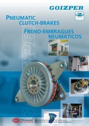
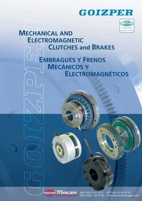
MECHANICAL AND<br />
ELECTROMAGNETIC<br />
CLUTCHES and BRAKES<br />
EN ISO 9001:2000<br />
Certificate: 01 100 5695<br />
EMBRAGUES Y FRENOS<br />
MECÁNICOS Y<br />
ELECTROMAGNÉTICOS<br />
DIST. AUTORIZADO<br />
®<br />
MEX (55) 53 63 23 31<br />
QRO (442) 1 95 72 60<br />
MTY (81) 83 54 10 18<br />
ventas@industrialmagza.com
INDEX<br />
Pág<br />
INTRODUCTION 2<br />
TECHNICAL INFORMATION 2<br />
Terms 2<br />
Acceleration time 4<br />
Calorific capacity 5<br />
Clutch size determination 6<br />
K safety factor values 7<br />
MECHANICAL CLUTCHES AND TORQUE LIMITERS 8<br />
Torque limiters serie 3.00 9<br />
Mechanical multi-plate clutches serie 3.13/3.23 10<br />
Mechanical multi-plate double clutches serie 3.24 11<br />
Mechanical clutches serie 3.83 12<br />
Actuator ring serie 3.15.__.802/3.24.__.802/3.85.__.802 13<br />
ELECTROMAGNETIC CLUTCHES AND BRAKES 14<br />
Electrical supply 14<br />
Electromagnetic multi-plate brakes serie 4.03/4.03B 16<br />
Electromagnetic slipring multi-plate clutches serie 4.05/4.05B 17<br />
Electromagnetic stationary field multi-plate<br />
clutches serie 4.25 18<br />
Assembly examples 4.03, 4.05B, 4.25 19<br />
Electromagnetic slipring toothed clutches serie 4.40 21<br />
Electromagnetic stationary field toothed<br />
clutches serie 4.41/4.42 22<br />
Electromagnetic slipring multi-plate clutches serie 4.50 25<br />
Electromagnetic multi-plate brakes serie 4.53 26<br />
Assembly examples 4.40, 4.41, 4.42, 4.50, 4.53 27<br />
Electromagnetic stationary field single-plate<br />
clutches serie 4.60/4.61/4.61A/4.61B 29<br />
Electromagnetic single-plate brakes serie 4.62/4.63/4.64 31<br />
Electromagnetic stationary field single-plate<br />
clutches serie 4.67/4.68/4.68A 32<br />
Electromagnetic safety brakes serie 4.74/4.75/4.76 33<br />
Assembly examples 4.60, 4.62, 4.64, 4.67, 4.75, 4.71 35<br />
Electrical accesories 36<br />
DIST. AUTORIZADO<br />
®<br />
MEX (55) 53 63 23 31<br />
QRO (442) 1 95 72 60<br />
MTY (81) 83 54 10 18<br />
ventas@industrialmagza.com
INDICE<br />
Pág<br />
INTRODUCCION 2<br />
INFORMACION TECNICA 2<br />
Definiciones 2<br />
Tiempo de aceleración 4<br />
Capacidad calorífica 5<br />
Determinación del tamaño del embrague 6<br />
Valores del factor de seguridad K 7<br />
EMBRAGUES MECANICOS Y LIMITADORES 8<br />
Limitadores de par serie 3.00 9<br />
<strong>Embragues</strong> mecánicos multidisco serie 3.13/3.23 10<br />
<strong>Embragues</strong> mecánicos dobles multidisco serie 3.24 11<br />
<strong>Embragues</strong> mecánicos serie 3.83 12<br />
Collarín de maniobra serie 3.15.__.802/3.24.__.802/3.85.__.802 13<br />
EMBRAGUES Y FRENOS ELECTROMAGNETICOS 14<br />
Alimentación eléctrica 14<br />
<strong>Frenos</strong> electromagnéticos multidisco serie 4.03/4.03B 16<br />
<strong>Embragues</strong> electromagnéticos multidisco<br />
con colector serie 4.05/4.05B 17<br />
<strong>Embragues</strong> electromagnéticos multidisco<br />
de bobina estática serie 4.25 18<br />
Ejemplos de montaje 4.03, 4.05B, 4.25 19<br />
<strong>Embragues</strong> electromagnéticos de dientes<br />
con colector serie 4.40 21<br />
<strong>Embragues</strong> electromagnéticos a dientes de<br />
bobina estática serie 4.41/4.42 22<br />
<strong>Embragues</strong> electromagnéticos multidisco<br />
con colector serie 4.50 25<br />
<strong>Frenos</strong> electromagnéticos multidisco serie 4.53 26<br />
Ejemplos de montaje 4.40, 4.41, 4.42, 4.50, 4.53 27<br />
<strong>Embragues</strong> electromagnéticos monodisco de<br />
bobina estática serie 4.60/4.61/4.61A/4.61B 29<br />
<strong>Frenos</strong> electromagnéticos monodisco serie 4.62/4.63/4.64 31<br />
<strong>Embragues</strong> electromagnéticos monodisco de<br />
bobina estática serie 4.67/4.68/4.68A 32<br />
<strong>Frenos</strong> electromagnéticos de seguridad serie 4.74/4.75/4.76 33<br />
Ejemplos de montaje 4.60, 4.62, 4.64, 4.67, 4.75, 4.71 35<br />
Accesorios eléctricos 36<br />
DIST. AUTORIZADO<br />
®<br />
MEX (55) 53 63 23 31<br />
QRO (442) 1 95 72 60<br />
MTY (81) 83 54 10 18<br />
ventas@industrialmagza.com
M E C H A N I C A L A N D E L E C T R O M A G N E T I C C L U T C H E S A N D B R A K E S<br />
TECHNICAL INFORMATION<br />
INFORMACION TECNICA<br />
INTRODUCTION<br />
Many of our customers already know operation<br />
and calculation of brakes and clutches. This<br />
information may be used confidently. However<br />
engineers and technicians facing brake and clutch<br />
problems for the first time may find them difficult<br />
to assimilate. We shall be pleased to provide<br />
advice on this subject. Do not hesitate to contact<br />
us.<br />
INTRODUCCION<br />
Muchos de nuestros clientes son conocedores del<br />
funcionamiento y cálculo de los frenos y embragues,<br />
y ellos manejan esta información con familiaridad.<br />
Sin embargo los ingenieros y técnicos que se<br />
enfrentan por primera vez con problemas de frenos<br />
y embragues pueden tener alguna dificultad en su<br />
asimilación. Nos ofrecemos para asesorarles en todo<br />
lo que esté a nuestro alcance, y les rogamos no<br />
duden en consultarnos.<br />
TERMS<br />
Firstly, let us define some concepts concerning<br />
moments and torques which are frequently used<br />
in calculation.<br />
DEFINICIONES<br />
Primeramente vamos a definir algunos conceptos<br />
en cuanto a momentos o pares se refiere y que se<br />
emplean frecuentemente en el cálculo.<br />
2<br />
Me. Clutch static torque.- This is the torque<br />
transmitted when the friction surfaces have<br />
no relative speed, that is the driver and driven<br />
parts are integral (clutch engaged).<br />
Par estático del embrague Me.- Es el par que<br />
transmite cuando las superficies de fricción no tienen<br />
velocidad relativa o sea son solidarias las partes<br />
conductora y conducida (Posición embragado).<br />
Md. Clutch dynamic torque.- This is the<br />
torque transmitted when there is a relative<br />
speed between the driver and the driven parts.<br />
It varies depending on the relative linear speed<br />
of the friction surfaces and on their lubricating<br />
condition, among other factors. This is the<br />
torque shown on the table of characteristics<br />
in our catalogue.<br />
Depending on the type of discs used, the ratio<br />
existing between the dynamic and the static<br />
torque is as follows:<br />
Steel/steel plates 1:1.8<br />
Lining/steel plates 1:1.3<br />
Sintered bronze/steel plates 1:1.5<br />
Par dinámico del embrague Md.- Es el par que<br />
transmite cuando hay una velocidad relativa entre<br />
las partes conductora y conducida. Este par varia en<br />
función de la velocidad lineal relativa de las superficies<br />
de fricción, del estado de lubricación de las mismas<br />
y de otros factores. Este par es el que aparece en las<br />
tablas de características de nuestro catálogo.<br />
Según qué tipo de láminas se empleen, la relación<br />
que hay entre el par dinámico y el estático es<br />
aproximadamente:<br />
Láminas acero/acero 1:1,8<br />
Láminas acero/guarnición 1:1,3<br />
Láminas acero/bronce sinterizado 1:1,5<br />
DIST. AUTORIZADO<br />
®<br />
MEX (55) 53 63 23 31<br />
QRO (442) 1 95 72 60<br />
MTY (81) 83 54 10 18<br />
ventas@industrialmagza.com
E M B R A G U E S Y F R E N O S M E C Á N I C O S Y E L E C T R O M A G N É T I C O S<br />
Mr. Clutch residual torque.- This is the torque<br />
transmitted by the clutch in the disengaged<br />
position.<br />
It depends on clutch position (horizontal or<br />
vertical), relative speed of plates or discs, oil flow<br />
rate and viscosity.<br />
With vertical assembly, the mobile frame or<br />
pressure plate, if it is not separated by springs,<br />
will be mounted at the lower position to prevent<br />
its weight from increasing residual torque.<br />
Par residual del embrague Mr .- Es el par que<br />
transmite el embraque en posición de<br />
desembragado.<br />
Depende de: La posición del embrague (horizontal<br />
o vertical), la velocidad relativa de las láminas o<br />
discos, de la viscosidad y caudal de aceite.<br />
En el caso de montaje vertical, la armadura móvil<br />
o plato de presión si no está separada por muelles,<br />
deberá montarse en la posición baja para evitar<br />
que su peso aumente el par residual.<br />
Mc. Load torque or static torque.- This is the<br />
torque required to overcome the work done by<br />
the machine and frictions. Its value is equal to<br />
the tangential force to be made multiplied by<br />
the length of the corresponding lever arm.<br />
M c = F • r<br />
Par resistente estático o par de carga Mc .-<br />
Es el par necesario para vencer el trabajo que<br />
realiza la máquina y los rozamientos. Su valor es<br />
igual al producto de la fuerza tangencial que hay<br />
que hacer, por la longitud del brazo de palanca<br />
correspondiente.<br />
M c = F • r<br />
Ma. Acceleration torque.- This is the torque<br />
required to accelerate masses up to a speed, in a<br />
required time. To work out this value the following<br />
formula is applied:<br />
M a =<br />
J(n 2 -n 1 )<br />
94 • t<br />
in daNm.<br />
J = Moment of inertia in kgm 2 .<br />
n 1 = priven shaft speed in r.p.m.<br />
n 2 = Driver shaft speed in r.p.m.<br />
t = Time in seconds.<br />
M a = Acceleration torque in daNm.<br />
In this formula all moments have to be referred<br />
to the clutch shaft, using the following formula:<br />
J red = J • i 2<br />
where J is the moment of inertia of the masses<br />
of a shaft at any given speed; J ref is the moment<br />
referred to the clutch shaft, and i is ratio between<br />
the former and the latter speeds.<br />
Par de aceleración Ma .- Es el par necesario<br />
para acelerar las masas hasta una velocidad en<br />
un tiempo deseado. Para calcular su valor se aplica<br />
la siguiente fórmula:<br />
M a =<br />
J(n 2 -n 1 )<br />
94 • t<br />
in daNm.<br />
J = momento de inercia en kgm 2 .<br />
n 1 = velocidad en r.p.m. del eje conducido.<br />
n 2 = velocidad en r.p.m. del eje conductor.<br />
t = tiempo en segundos.<br />
M a = par de aceleración en daNm.<br />
En esta fórmula todos los momentos tienen que<br />
ser referidos al eje del embrague, lo que se obtiene<br />
por la relación siguiente:<br />
J red = J • i 2<br />
siendo J el momento de inercia de las masas de<br />
un eje a una velocidad cualquiera; J red, el<br />
momento reducido al eje del embrague, e i la<br />
relación de velocidades entre el primero y el<br />
segundo.<br />
3<br />
DIST. AUTORIZADO<br />
®<br />
MEX (55) 53 63 23 31<br />
QRO (442) 1 95 72 60<br />
MTY (81) 83 54 10 18<br />
ventas@industrialmagza.com
M E C H A N I C A L A N D E L E C T R O M A G N E T I C C L U T C H E S A N D B R A K E S<br />
If the masses to be accelerated have a linear<br />
motion, their moments are referred to the<br />
clutch shaft, applying the following formula:<br />
Si las masas a acelerar tienen un movimiento<br />
lineal, sus momentos se reducen al eje del<br />
embrague, por la siguiente fórmula:<br />
J red. = 91 • m •<br />
v 2<br />
n 2<br />
J red. = 91 • m •<br />
v 2<br />
n 2<br />
m<br />
V<br />
n<br />
= Masses in linear motion, in kg.<br />
= Speed of the above mentioned masses<br />
in m/sec.<br />
= R.p.m. of the clutch.<br />
J red = Moment of inertia in kgm 2 referred<br />
to the clutch shaft.<br />
m<br />
V<br />
n<br />
= Masas en movimiento lineal (kg).<br />
= Velocidad de las citadas masas en<br />
m/seg.<br />
= revoluciones por minuto del embrague.<br />
J red = momento de inercia en kgm 2 reducido<br />
al eje del embrague.<br />
4<br />
M t . Total torque.- This is the sum of the load<br />
torque and the acceleration torque.<br />
M t = M c + M a<br />
The J of a 100 mm thick solid iron cylinder, it<br />
works out by means of the following formula:<br />
J = 77 • D 4<br />
Where D is its external diameter in m, and J is<br />
the moment of inertia in Kgm 2 .<br />
M t = Par resistente total<br />
Su valor resulta de la suma de los pares de<br />
carga y aceleración.<br />
M t = M c + M a<br />
El J de un cilindro macizo de hierro, de 100<br />
mm de espesor, se obtiene por la fórmula:<br />
J = 77 • D 4<br />
Siendo D su diámetro exterior en m J es el<br />
momento de inercia en kgm 2 .<br />
ACCELERATION TIME<br />
TIEMPO DE ACELERACION<br />
The acceleration time can be calculated using<br />
the following formula:<br />
Para hallar el tiempo de aceleración, utilice la<br />
siguiente fórmula:<br />
t a =<br />
J (n 2 ± n 1 )<br />
9,55 (M t ± M c )<br />
in seconds<br />
t a =<br />
J (n 2 ± n 1 )<br />
9,55 (M t ± M c )<br />
in seconds<br />
n 2 - n 1<br />
= where acceleration or deceleration<br />
is concerned.<br />
n 2 + n 1 = where inversion is concerned.<br />
M t - M c = in Nm where acceleration is<br />
concerned.<br />
M t + M c = in Nm where deceleration is<br />
concerned.<br />
n 2 - n 1<br />
= en casos de aceleración o<br />
deceleración.<br />
n 2 + n 1 = en casos de inversión.<br />
M t - M c = en Nm, en casos de aceleración.<br />
M t + M c = en Nm, en casos de deceleración.<br />
DIST. AUTORIZADO<br />
®<br />
MEX (55) 53 63 23 31<br />
QRO (442) 1 95 72 60<br />
MTY (81) 83 54 10 18<br />
ventas@industrialmagza.com
E M B R A G U E S Y F R E N O S M E C Á N I C O S Y E L E C T R O M A G N É T I C O S<br />
CALORIFIC CAPACITY<br />
In order to calculate the produced heat Q during<br />
every operation, use the following formula:<br />
CAPACIDAD CALORIFICA<br />
Para calcular el calor Q producido en cada<br />
maniobra, aplique la siguiente fórmula:<br />
Q =<br />
J (n 2 ± n 1 ) 2 M t<br />
•<br />
764 • 10 3 (M t ± M c )<br />
in kcal.<br />
Q =<br />
J (n 2 ± n 1 ) 2 M t<br />
•<br />
764 • 10 3 (M t ± M c )<br />
in kcal.<br />
The work produced by the clutch or brake<br />
during every operation will be transformed<br />
into heat, it will be absorbed by the friction<br />
surfaces of the plates or dissipated into the air,<br />
without exceeding the calorific capacity of the<br />
clutch.<br />
In order to work out the maximum frequency<br />
per hour of clutch operations the following<br />
should be taken into account: friction surface<br />
area of the discs in cm2, number of friction<br />
surfaces and calorific value (dissipation capacity<br />
in Kcal/cm2 hour). For this last element and<br />
according to the type of plate, the following<br />
values should be considered:<br />
1) steel/steel plates<br />
Splash lubrication ≈ 0.4 ÷ 0.5<br />
Inside lubrication ≈ 0.6 ÷ 0.7<br />
Maximum temperature of the friction surfaces:<br />
200° C.<br />
2) sintered bronze/steel plates<br />
Dry running = 0,4 ÷ 0,5<br />
Splash lubrication 1 ÷ 1.2<br />
Inside lubrication 1,5 ÷ 2<br />
Maximum temperature: 500° C.<br />
3) lining/steel plates<br />
Single-plate units, 1 ÷ 2 dry running.<br />
Multi-plate units, 0,2 ÷ 0,3 dry running.<br />
Maximum temperature: 300° C.<br />
El trabajo producido por el embrague o freno<br />
en cada maniobra que se transforma en calor<br />
y es absorbido o transmitido al aire por las<br />
superficies de fricción de los discos, sin<br />
sobrepasar la capacidad calorifica del embrague.<br />
Para calcular la frecuencia máxima de maniobras<br />
por hora admisibles para el embrague, hay que<br />
tener en cuenta: superficies de rozamiento de<br />
los discos en cm2, número de las mismas y el<br />
valor calorífico (Poder de disipación en Kcal/cm2<br />
hora). Para este último factor y según el tipo<br />
de disco se pueden considerar los siguientes<br />
valores:<br />
1) discos acero/acero<br />
Lubricación por barboteo ≈ 0,4 ÷ 0,5<br />
Lubricación interior ≈ 0,6 ÷ 0,7<br />
La temperatura de las superficies de rozamiento<br />
no debe sobrepasar 200° C.<br />
2) discos acero/sinterizado<br />
En seco = 0,4 ÷ 0,5<br />
Lubricación por barboteo 1 ÷ 1,2<br />
Lubricación interior 1,5 ÷ 2<br />
La temperatura no debe ser superior a 500° C.<br />
3) discos acero/guarnición<br />
Monodiscos 1 ÷ 2 en seco<br />
Multidiscos 0,2 ÷ 0,3 en seco.<br />
La temperatura máxima será 300° C.<br />
5<br />
DIST. AUTORIZADO<br />
®<br />
MEX (55) 53 63 23 31<br />
QRO (442) 1 95 72 60<br />
MTY (81) 83 54 10 18<br />
ventas@industrialmagza.com
M E C H A N I C A L A N D E L E C T R O M A G N E T I C C L U T C H E S A N D B R A K E S<br />
6<br />
Furthermore, the energy produced per operation<br />
and per cm2 of surface area should not exceed:<br />
* 25-50 cal/cm2 for wet operation of sintered<br />
bronze/steel plates.<br />
* 6-12 cal/cm2 for wet operation of steel/steel<br />
plates.<br />
* 25-35 cal/cm2 for dry operation sintered<br />
bronze/steel plates.<br />
* 50-100 cal/cm2 for dry operation of lining/steel<br />
or cast iron plates.<br />
DETERMINING CLUTCH SIZE<br />
In order to determine clutch size, consider the<br />
máximum resisting torque to be overcome.<br />
While in operation in most cases impact<br />
unknown peaks may happen. For that reason<br />
a service factor K determined by experience<br />
should be taken into consideration. It will<br />
depend on the characteristics of driving and<br />
driven machines.<br />
M d ≥ M t • K<br />
If the machine is not equipped with a flywheel,<br />
calculate clutch torque using motor power, with<br />
the following formula:<br />
M d = 955 •<br />
P m<br />
n<br />
P m = Motor power in kw.<br />
n = Clutch speed in r.p.m.<br />
K = Safety factor.<br />
M d = Dynamic clutch torque in daNm.<br />
For some applications with a high speed and<br />
operation frequency, the calculation should be<br />
complementad by a study on heat dissipation<br />
based on empirical formulations. Please let us do<br />
this for you.<br />
K<br />
Además, la energía producida por operación y<br />
por cm2 de superficie no deberá pasar de:<br />
* 25-50 cal/cm2 para discos de acero-bronce<br />
sinterizado en aceite.<br />
* 6-12 cal/cm2 para acero-acero en aceite.<br />
* 25-35 cal/cm2 acero-bronce sinterizado en seco.<br />
* 50-100 cal/cm2 para acero o fundiciónguarnición<br />
orgánica en seco.<br />
DETERMINACIÓN DEL TAMAÑO DEL<br />
EMBRAGUE<br />
Para determinar el tamaño del embrague, se<br />
tendrá en cuenta el par resistente máximo que<br />
tiene que vencer.<br />
Durante el funcionamiento se pueden producir<br />
puntas de choque desconocidas en la mayoría de<br />
los casos; por esta razón hay que tener en cuenta<br />
un factor de seguridad K determinado por la<br />
experiencia, y que depende de la naturaleza de<br />
las máquinas motriz y receptora.<br />
M d ≥ M t • K<br />
En el caso de que la máquina no lleve incorporado<br />
un volante de inercia se puede calcular el par del<br />
embrague partiendo de la potencia del motor,<br />
en cuyo caso se aplicará la siguiente fórmula:<br />
M d = 955 •<br />
P m<br />
n<br />
P m = Potencia del motor en kw.<br />
n = Velocidad del embrague en r.p.m.<br />
K = Factor de seguridad.<br />
M d = Par dinámico del embrague en daNm.<br />
En ciertas aplicaciones, en las que la velocidad y<br />
frecuencia de maniobras es elevada, el cálculo<br />
debe ser completado con un estudio de disipación<br />
del calor cuyo cálculo basado en fórmulas<br />
empíricas, rogamos nos confíen.<br />
K<br />
DIST. AUTORIZADO<br />
®<br />
MEX (55) 53 63 23 31<br />
QRO (442) 1 95 72 60<br />
MTY (81) 83 54 10 18<br />
ventas@industrialmagza.com
E M B R A G U E S Y F R E N O S M E C Á N I C O S Y E L E C T R O M A G N É T I C O S<br />
K SAFETY FACTOR VALUES<br />
Type of driving machine<br />
Type of driven machine<br />
Electric<br />
motor<br />
Internal<br />
combustion<br />
engine 4 or<br />
6 cylinders<br />
Internal<br />
combustion<br />
engine 2 or<br />
3 cylinders<br />
Infernal<br />
combustion<br />
engine<br />
1-cylinder<br />
Lower J<br />
Centrifugal pumps, small fans, centrifugal compressors<br />
1,5<br />
1,8<br />
2<br />
2,5<br />
Low J<br />
Elevators, Large fans, Belt conveyors, Wood and metal machine<br />
tools, Small textile Machines<br />
1,7<br />
2<br />
2,2<br />
2,8<br />
Medium J<br />
Rotary furnaces, Elevators, Mixers, Shearing machines, Stamping<br />
machines, Pump and piston compressors, Sharpening machines,<br />
Heavy textile machines, Mills.<br />
2<br />
2,3<br />
2,5<br />
3,2<br />
High J and high load peaks<br />
Shovels, Polishing machines, Tractors, Light metal rollers, Crushing<br />
machines, Large fans, Molding presses, Locomotives, Large<br />
piston pumps, Cranes.<br />
2,5<br />
2,7<br />
3<br />
3,5<br />
Higher J and high load peaks<br />
Forging presses, Large piston compressors, Steel and rubber<br />
rollers, Saws, Carrier rollers, Filing machines, Wire drawing<br />
machines, Plate bending machines, Large crushing machines,<br />
Paper calenders, Spinning machines.<br />
3<br />
3,2<br />
3,5<br />
4<br />
7<br />
VALORES DEL FACTOR DE SEGURIDAD K<br />
Tipo de máquina receptora<br />
Motor<br />
eléctrico<br />
Tipo de máquina motriz<br />
Motor<br />
explosión<br />
4 ó 6 cilind.<br />
Motor<br />
explosión<br />
2 ó 3 cilind.<br />
Motor<br />
explosion<br />
Monocilindr.<br />
J muy reducido<br />
Bombas centrífugas, pequeños ventiladores, compresor<br />
centrífugo.<br />
1,5<br />
1,8<br />
2<br />
2,5<br />
J pequeño<br />
Elevadores, Grandes ventiladores, Transportadores a cinta,<br />
Máquinas herramientas para madera y metal, Pequeña máquina<br />
textil.<br />
1,7<br />
2<br />
2,2<br />
2,8<br />
J mediano<br />
Horno rotativo, montacargas, Mezcladoras, Cizalla, Máquina<br />
de estampar, Bomba y compresor de pistón, Afiladora, Máquina<br />
textil pesada, Molinos<br />
2<br />
2,3<br />
2,5<br />
3,2<br />
J elevado y fuertes puntas de carga<br />
Palas, Pulidoras, Tractores, Laminadoras de metales ligeros,<br />
Trituradoras, Grandes ventiladores, Prensas de matrizar,<br />
Locomotoras, Bombas grandes de pistón, Grúas.<br />
2,5<br />
2,7<br />
3<br />
3,5<br />
J muy elevado y fuertes puntas de carga<br />
Prensas de forjar, Compresor de pistón grande, Laminadoras<br />
para acero y caucho, Sierras alternativas, Rodillos transportadores,<br />
Limadoras, Bancos de estiraje, Plegadoras, Grandes trituradores,<br />
Calandras para papel, Centrifugadoras.<br />
3<br />
3,2<br />
3,5<br />
4<br />
DIST. AUTORIZADO<br />
®<br />
MEX (55) 53 63 23 31<br />
QRO (442) 1 95 72 60<br />
MTY (81) 83 54 10 18<br />
ventas@industrialmagza.com
M E C H A N I C A L A N D E L E C T R O M A G N E T I C C L U T C H E S A N D B R A K E S<br />
MECHANICAL CLUTCHES<br />
AND TORQUE LIMITERS<br />
EMBRAGUES MECANICOS<br />
Y LIMITADORES<br />
This section shows:<br />
- Series 3.00 multi-plate torque limiters.<br />
- Series 3.15-3.23 single multi-plate clutches.<br />
- Series 3.24 double multi-plate clutches.<br />
- Series 3.83 single or twin-plate clutches.<br />
- Actuator rings.<br />
Mechanical clutches are used for braking and<br />
clutching operations. Manufacturing could be<br />
done for oil or dry running applications.<br />
Torque limiters or slipping clutches are usually<br />
applied in order to protect against overloads in<br />
various types of installations.<br />
En este apartado se ofrecen:<br />
- Limitadores de par multidiscos de la serie 3.00.<br />
- <strong>Embragues</strong> simples multidisco de la serie 3.15-<br />
3.23.<br />
- <strong>Embragues</strong> dobles multidisco de la serie 3.24.<br />
- <strong>Embragues</strong> mono y bidiscos de la serie 3.83.<br />
- Y los collarines de maniobra para los mismos.<br />
Los embragues multidisco se utilizan tanto en<br />
aplicaciones de freno como de embrague. Se<br />
pueden fabricar para su uso en baño de aceite o<br />
en seco.<br />
Los Iimitadores o embragues de resbalamiento<br />
se aplican normalmente como protectores de<br />
sobrecarga en instalaciones diversas.<br />
8<br />
DIST. AUTORIZADO<br />
®<br />
MEX (55) 53 63 23 31<br />
QRO (442) 1 95 72 60<br />
MTY (81) 83 54 10 18<br />
ventas@industrialmagza.com
E M B R A G U E S Y F R E N O S M E C Á N I C O S Y E L E C T R O M A G N É T I C O S<br />
Serie 3.00<br />
TORQUE LIMITERS • LIMITADORES DE PAR<br />
Serie 3.00<br />
Size 02 05 08 16 23 32 64 12 25<br />
Torque Nm 20 50 80 160 230 320 640 1280 2560<br />
Weight Kg 0,8 1,5 2 3,5 5 6,5 10,5 20,5 38<br />
9<br />
J Total Kg cm 2 5 25 45 75 150 225 250 1.250 3.750<br />
Ø A<br />
min. 15 15 20 25 25 25 35 40 50<br />
máx. 22 32 40 45 50 55 70 80 100<br />
Ø B 30 40 50 55 65 65 95 95 115<br />
Ø D 65 93 103 120 130 150 190 230 295<br />
Ø E - - - - - - - - -<br />
Ø F<br />
min. 15 15 25 35 35 35 38 38 45<br />
máx. 40 60 63 63 67 67 85 105 120<br />
L 44 49 54 62 66 75 85 105 125<br />
M máx. 40 60 60 62 68 66 95 105 110<br />
N 6 8 8 10 10 10 12 12 15<br />
O 33 37,5 43 46 51 57 63 77 94<br />
DIST. AUTORIZADO<br />
®<br />
MEX (55) 53 63 23 31<br />
QRO (442) 1 95 72 60<br />
MTY (81) 83 54 10 18<br />
ventas@industrialmagza.com
M E C H A N I C A L A N D E L E C T R O M A G N E T I C C L U T C H E S A N D B R A K E S<br />
Serie 3.13 / 3.23<br />
SERIE 3.13 SERIE 3.23<br />
MECHANICAL MULTI-PLATE CLUTCHES • EMBRAGUES MECÁNICOS MULTIDISCO<br />
10<br />
Serie 3.13 3.23<br />
Size 05 08 11 16 23 32 45 64 90 05 08 11 16 23 32<br />
Torque Nm 50 80 110 160 230 320 450 640 900 50 80 110 160 230 320<br />
Weight Kg 2 3,5 4,5 6 7 9 11 16 18 2,5 4 5 6,5 7,5 10<br />
Speed max min -1 3.000 2.800 2.600 2.400 2.200 2.000 1.900 1.800 1.800 3.000 2.800 2.600 2.400 2.200 2.000<br />
Interior 9 20 30 40 60 110 180 350 500 15 37 50 60 75 112<br />
J Int. flange Kg cm 2 12 30 40 60 80 140 180 300 500 15 22 25 50 75 140<br />
Ext. flange 12 30 50 70 100 170 200 400 600 15 30 37 62 90 150<br />
Engagem. Force 140 170 200 260 300 350 400 450 500 120 160 190 250 280 330<br />
N<br />
Diseng. force 75 90 110 130 150 180 210 270 290 60 80 90 130 150 170<br />
Stroke - Carrera mm 10 10 10 12 12 12 14 17 17 13 13 13 14 14 16<br />
Ø A min. 21 21 21 21 21 26 26 41 41 21 21 21 26 21 26<br />
Ø A max. 32 36 40 45 50 55 60 70 75 32 32 35 38 43 48<br />
Ø B 36 40 45 55 55 65 70 80 86 42 42 45 46 53 58<br />
Ø C 86 95 105 115 125 140 155 175 190 86 95 105 115 125 140<br />
Ø D 90 100 110 120 130 145 160 185 200 90,5 99 113 120 130 145<br />
Ø E 102 120 130 140 150 165 180 210 220 102 125 130 140 150 165<br />
Ø F 115 140 150 160 170 185 200 235 240 115 145 150 160 170 185<br />
Ø H 58 78 78 85 85 110 110 132 132 70 78 82 85 92 100<br />
L 60 70 70 80 80 100 100 126 126 81 86 86 95 95 108<br />
M 3 3 3 4 4 4 4 4 4 3 3 3 4 4 4<br />
N 6 8 8 10 10 10 10 10 10 6 8 8 10 10 10<br />
P 42 51 51 60 60 76 74 91 90 55 60 60 65 65 76<br />
Ø R 4x6,5 4x8,5 4x8,5 4x10,5 6x10,5 6x10,5 6x10,5 6x10,5 6x10,5 4x6,5 4x8,5 4x8,5 4x10,5 6x10,5 6x10,5<br />
S 2 2 2 3 3 3 3 3 3 2 2 2 3 3 3<br />
T 11 11 11 11 11 16 16 20 20 11 11 11 15 15 15<br />
U 18 18 18 22 22 25 25 36 36 21 21 21 26 26 26<br />
Ø Z 65 88 88 96 96 122 122 152 152 85 92 97 100 107 115<br />
DIST. AUTORIZADO<br />
®<br />
MEX (55) 53 63 23 31<br />
QRO (442) 1 95 72 60<br />
MTY (81) 83 54 10 18<br />
ventas@industrialmagza.com
E M B R A G U E S Y F R E N O S M E C Á N I C O S Y E L E C T R O M A G N É T I C O S<br />
Serie 3.24<br />
MECHANICAL MULTI-PLATE DOUBLE CLUTCHES • EMBRAGUES MECÁNICOS DOBLES MULTIDISCO<br />
Serie 3.24<br />
Size 05 08 11 16 23 32<br />
Torque Nm 50 80 110 160 230 320<br />
Weight Kg 3,8 6,5 8 10 11,5 16<br />
11<br />
Speed max. min -1 3.000 3.000 3.000 2.800 2,600 2.500<br />
J int. Kg cm 2 25 50 60 87 112 162<br />
Engagem. force 120 160 190 250 280 330<br />
N<br />
Diseng. force 60 80 90 130 150 170<br />
Stroke - Carrera mm 13 13 13 14 14 16<br />
Ø A min. 21 21 21 21 21 26<br />
Ø A max. 32 32 35 38 43 48<br />
Ø B 40 42 45 46 53 58<br />
Ø C min. 44 44 48 49 56 61<br />
Ø D 90,5 99 113 120 130 145<br />
Ø H 70 78 82 85 92 100<br />
L 1 136 148 148 158 158 185<br />
N 6 8 8 10 10 10<br />
N 1 10 10 10 12 12 14<br />
P 55 60 60 65 65 76<br />
T 11 11 11 15 15 15<br />
U 21 21 21 26 26 26<br />
Ø Z 85 92 97 100 107 115<br />
DIST. AUTORIZADO<br />
®<br />
MEX (55) 53 63 23 31<br />
QRO (442) 1 95 72 60<br />
MTY (81) 83 54 10 18<br />
ventas@industrialmagza.com
M E C H A N I C A L A N D E L E C T R O M A G N E T I C C L U T C H E S A N D B R A K E S<br />
Serie 3.83<br />
MECHANICAL CLUTCHES • EMBRAGUES MECÁNICOS<br />
Serie 3.83<br />
Size 18 25* 36 55* 75* 76**<br />
Torque Nm 1800 2560 3600 5500 7500 11000<br />
12<br />
Weight Kg 36 42 55 62 74 90<br />
Speed max. min -1 2.500 2.500 1.800 1.800 1.500 1.500<br />
int. 0,25 0,30 0,85 1,10 2,4 2,90<br />
J Kg m 2<br />
Ext. 0,18 0,23 0,40 0,90 1,80 2,75<br />
Engagem. Forze 2.200 2.200 4.000 4.000 4.500 4.500<br />
N<br />
Diseng. Forze 1.100 1.100 2.000 2.000 2.250 2.250<br />
Stroke mm 23 24 32 32 37 37<br />
min. 38 38 55 55 65 65<br />
Ø A<br />
max. 90 90 120 120 110 110<br />
Ø B 145 145 185 185 185 185<br />
Ø C 168 168 214 214 214 214<br />
Ø D 188 188 240 240 240 240<br />
Ø E 310 310 430 430 490 490<br />
Ø F f7 330 330 460 460 520 520<br />
Ø G 266 266 377 377 435 435<br />
I 120 120 134 134 132 132<br />
L 155 155 185 210 235 265<br />
M 25 25 42 42 47 50<br />
N 25 40 20 45 55 80<br />
P 113 113 125 150 171 197<br />
Ø R 8x10,5 8x10,5 6x13 6x14,5 6x17 6x17<br />
T 20 20 26 26 30 30<br />
U 35 35 46 46 54 54<br />
*TWIN-PLATE • DOBLE DISCO<br />
**TRIPLE PLATE • TRIPLE DISCO<br />
DIST. AUTORIZADO<br />
®<br />
MEX (55) 53 63 23 31<br />
QRO (442) 1 95 72 60<br />
MTY (81) 83 54 10 18<br />
ventas@industrialmagza.com
E M B R A G U E S Y F R E N O S M E C Á N I C O S Y E L E C T R O M A G N É T I C O S<br />
Serie 3.15.__.802 / 3.24.__ .802 / 3.85.__ .802<br />
BRONZE ACTUATOR RING • COLLARÍN DE MANIOBRA, DE BRONCE<br />
CODE Size A B C D E F G H<br />
3.15.05.802 05 58,5 72 78 8 7 14 94 10,8<br />
3.14.11.802<br />
08<br />
11<br />
78,5 94 100 9 10 16 118 10,8<br />
13<br />
Serie 3.13<br />
3.15.16.802<br />
3.15.32.802<br />
16<br />
23<br />
32<br />
45<br />
85,5 102 113 10 11 18 130 10,8<br />
111 128 140 12 12 18 160 15,8<br />
3.15.64.802<br />
64<br />
90<br />
133 155 170 15 16 24 195 19,8<br />
3.24.05.802 05 70,5 87 90 10 15 14 110 10,8<br />
Serie 3.23 - 3.24<br />
3.24.08.802 08 78,5 95 100 10 15 16 122 10,8<br />
3.24.11.802 11 82,5 100 104 10 15 16 126 10,8<br />
3.24.16.802 16 86 102 106 10 15 18 130 14,8<br />
3.24.23.802 23 93 110 112 10 15 24 140 14,8<br />
3.24.32.802 32 101 118 120 10 15 24 154 14,8<br />
Serie 3.83<br />
3.85.18.802<br />
3.85.55.802<br />
18<br />
25<br />
36<br />
55<br />
169 194 206 18 18 24 230 19,8<br />
215 248 250 20 25 32 290 25,8<br />
3.85.76.802<br />
75<br />
76<br />
215 244 250 26 25 34 290 29,8<br />
DIST. AUTORIZADO<br />
®<br />
MEX (55) 53 63 23 31<br />
QRO (442) 1 95 72 60<br />
MTY (81) 83 54 10 18<br />
ventas@industrialmagza.com
M E C H A N I C A L A N D E L E C T R O M A G N E T I C C L U T C H E S A N D B R A K E S<br />
ELECTROMAGNETIC<br />
CLUTCHES AND BRAKES<br />
EMBRAGUES Y FRENOS<br />
ELECTROMAGNÉTICOS<br />
14<br />
ELECTRICAL SUPPLY<br />
The industrial applications of electromagnetic<br />
clutches and brakes are very frequent due to the<br />
progress in designing of machines and because<br />
they perform with required functions.<br />
Power Supply<br />
When coil body is static, the input is made by<br />
the strip through AMP terminals (6.35 Faston).<br />
For connection with slipring (rotating coil body),<br />
the intake (positive pole) is made through the<br />
brush which rubs the slipring. The negative<br />
pole is earthed.<br />
Carbon-brush is used for dry operation and if<br />
the assembly is made in oil-bath the brush will<br />
be braided copper. It must be also considered<br />
that with oil bath and with circumferential<br />
speeds of the slipring above 10 m/s it is advisable<br />
to fit two adjacent brushes, as in this way the<br />
electrical interruption caused by the oil-film is<br />
avoided. The advisable limit speed for use of the<br />
braided copper brush is 20 m/s. The brush must<br />
be mounted perpenticular to the friction surface,<br />
allowing a maximum tolerance inclination of 2º.<br />
Coil Power Supply<br />
The direct current supply voltage is 24 V. and<br />
must not exceed +5% or go below -10% of its<br />
nominal value. The supply interruption must<br />
be foreseen in the d.c. circuit in order to<br />
obtain shorter stopping times.<br />
To obtain a quicker clutch or brake interlocking<br />
the following accelerating methods may be<br />
applied:<br />
Set in series with the magnet coil an ohmic<br />
resistance of double value of the coil resistance<br />
in order that the time constant t = L/R be of less<br />
value. Thus we obtain a quicker current rise.<br />
Obviously the supply voltage is higher in order<br />
to obtain the same final value of the current.<br />
A better solution than the previous one is to<br />
supply directly the coil in a split second with a<br />
voltage of 3 or 4 times the nominal voltage value.<br />
ALIMENTACIÓN ELECTRICA<br />
Las aplicaciones industriales de los embragues y<br />
frenos electromagnéticos son cada vez más<br />
frecuentes, debido al progreso en el diseño de la<br />
máquina, respondiendo perfectamente a las<br />
funciones exigidas.<br />
Tomas de corriente<br />
Cuando el cuerpo de bobina es estático, la toma<br />
de corriente se hará por medio de la regleta, a<br />
través de las bornas AMP (Fastón de 6.35). Para<br />
la ejecución con anillo colector (cuerpo de bobina<br />
giratorio), la toma (polo positivo) se realiza por<br />
medio de la escobilla que roza con aquél en su<br />
periferia. El polo negativo está unido a masa.<br />
Para funcionamiento en seco, la escobilla será de<br />
carbón, y si el montaje se realiza en baño de<br />
aceite, de cobre trenzado. Hay que tener en<br />
cuenta también que en baño de aceite y con<br />
velocidades circunferenciales del anillo colector<br />
superiores a 10 m/s es aconsejable colocar 2<br />
escobillas contiguas, porque de esta forma se<br />
evita la interrupción eléctrica provocada por el<br />
film de aceite.<br />
La velocidad limite aconsejable para la utilización<br />
de la escobilla de cobre trenzado es de 20 m/s.<br />
La escobilla tiene que ser montada perpendicular<br />
a la superficie de rozamiento, admitiendo como<br />
máximo una tolerancia de 2º de inclinación.<br />
Alimentación de la bobina<br />
La tensión de corriente continua de alimentación,<br />
normalmente es de 24 V. y no debe variar de +5%<br />
y de -10% con respecto a su valor nominal. La<br />
interrupción de la corriente se debe prever en el<br />
circuito de continua con el fin de obtener unos<br />
tiempos de parada más cortos.<br />
Para conseguir un enclavamiento más rápido del<br />
embrague o freno, se puede recurrir a los métodos<br />
aceleradores siguientes:<br />
Colocar en serie con la bobina una resistencia<br />
óhmica de valor doble a la resistencia de la bobina,<br />
con objeto de que la constante de tiempo t= L/R<br />
sea menor, consiguiendo así una elevación más<br />
rápida de la corriente. Como es natural, la tensión<br />
de alimentación será mayor, con el fin de<br />
conseguir el mismo valor final de la corriente.<br />
Solución de más efecto que la anterior, es<br />
alimentar la bobina directamente con una tensión<br />
igual a 3 ó 4 veces la tensión nominal, durante<br />
una fracción de segundo.<br />
DIST. AUTORIZADO<br />
®<br />
MEX (55) 53 63 23 31<br />
QRO (442) 1 95 72 60<br />
MTY (81) 83 54 10 18<br />
ventas@industrialmagza.com
E M B R A G U E S Y F R E N O S M E C Á N I C O S Y E L E C T R O M A G N É T I C O S<br />
SUPPLY CIRCUITS<br />
When a current failure happens in the clutch an<br />
over-voltage to be absorved will appear in the<br />
coil.<br />
In order to protect the contact points of the relays<br />
a condenser of 2 μF capacity has to be installed<br />
for coils up to 60 watts and of 4 μF capacity for<br />
bigger coils.<br />
1. Protection of the coil by means of a varistor.<br />
2. For higher tensions than 48V the varistor must<br />
be mounted in series with a diode (2A - 1000 V).<br />
The clutch releasing times retard slightly using<br />
these protections.<br />
3. Normal excitation of the coil.<br />
4. Excitation with additional resistance.<br />
The connection time reduces by approximately<br />
70% with regard to the previous case.<br />
ESQUEMAS DE ALIMENTACION<br />
En el momento de la ruptura de la corriente en<br />
el embrague, se produce en la bobina una<br />
sobretensión que debe ser amortiguada.<br />
Para proteger los contactos de los relés, se monta<br />
en paralelo con ellos un condensador de capacidad<br />
2μF para bobinas hasta 60 Watios y 4μF para<br />
bobinas de mayor potencia.<br />
1. Protección de la bobina por medio de un<br />
varistor.<br />
2. Protección de la bobina por medio de un<br />
varistor en serie con un diodo (2A - 1000 V),<br />
para tensiones superiores a 48 V. Los tiempos<br />
de desembrague se retardan ligeramente,<br />
utilizando estas protecciones.<br />
3. Excitación normal de la bobina.<br />
4. Excitación con resistencia adicional. El tiempo<br />
de conexión se reduce un 70% aproximadamente<br />
con respecto al caso anterior.<br />
15<br />
5. Excitation with momentary overvoltage.<br />
The connection time will be reduced by<br />
approximately an 80%.<br />
6. Excitation with overvoltage and with additional<br />
resistance and condenser.<br />
7. Excitation with overvoltage by means of<br />
discharge of a condenser.<br />
The connection time will be reduced by<br />
approximately a 90%<br />
8. Clutch ralease by excitation with reversed<br />
polarity.<br />
The disconnecting time will be reduced by a<br />
50%.<br />
5. Excitación con sobretensión momentánea. El<br />
tiempo de conexión se reduce un 80% aprox.<br />
6. Excitación con sobretensión y con resistencia<br />
y condensación adicionales.<br />
El tiempo de conexión se reduce un 85% aprox.<br />
7. Excitación con sobretensión por descarga de<br />
un condensador.<br />
El tiempo de conexión se reduce un 90% aprox.<br />
8. Desembrague a base de excitación con<br />
polaridad invertida.<br />
El tiempo de desconexión se reduce un 50%.<br />
DIST. AUTORIZADO<br />
®<br />
MEX (55) 53 63 23 31<br />
QRO (442) 1 95 72 60<br />
MTY (81) 83 54 10 18<br />
ventas@industrialmagza.com
M E C H A N I C A L A N D E L E C T R O M A G N E T I C C L U T C H E S A N D B R A K E S<br />
Serie 4.03 / 4.03 B<br />
SERIE 4.03<br />
SERIE 4.03 B<br />
ELECTROMAGNETIC MULTI-PLATE BRAKES • FRENOS ELECTROMAGNÉTICOS MULTIDISCO<br />
16<br />
Serie 403<br />
4.03 - 4.03 B<br />
Size 02 05 11 11e 23 23e 32 45 64<br />
Torque Nm 20 50 110 110 230 230 320 450 640<br />
Voltage V 24*<br />
Power W 19 24 38 38 54 46 67 67 75<br />
Weight Kg 1,6 2,8 4,2 4,2 6,4 6,4 9 9,8 13<br />
Speed max. min -1 3.500 3.200 3.000 3.000 2.600 2.600 2.200 2.200 2.000<br />
int. 2 5 15 15 65 65 112 125 190<br />
J Kg cm 2<br />
ext. 20 62 150 150 375 375 620 750 1.250<br />
Ø A min. 16 15 21 21 26 26 26 26 41<br />
Ø A max. 28 32 38 45 45 55 55 55 65<br />
B 20 23 26 26 30 27 33,5 33,5 35<br />
Ø C min. 15 21 21 21 31 31 41 41 81<br />
Ø C max. 40 53 60 70 70 80 85 85 100<br />
Ø D 93 114 134 140 168 168 198 198 216<br />
Ø E 50 60 72 80 92 95 110 110 120<br />
Ø E 1 56 75 90 90 100 116 116 116 130<br />
Ø F 85 100 122 125 152 152 182 182 195<br />
G 18 23 28 29 32 32 36,5 39,5 46<br />
Ø H 42 55 68 68 75 90 90 90 100<br />
I 2 5 7 7 5 5 6 6 8<br />
L 38 48 55 55 58,5 64,5 66 69 77,5<br />
L 1 36 44 52 52 60 58,5 67 70 74<br />
Ø M 80 95 120 120 142 142 170 170 184<br />
Ø Q 37 45 60 60 65 80 80 80 90<br />
Ø R 4xM6 4xM6 4xM8 4xM6 5xM10 5xM10 5xM10 5xM10 5xM10<br />
ØR 1 - 4 a 90º M6 M8 M8 M8 M10 M10 M10 M10 M12<br />
S 20 22 22 22 25 28 28 28 31<br />
T 12 12 16 16 16 16 16 16 20<br />
T 1 max. 5 7 8 8 9 9 9 9 16<br />
UxV 2,5x12 5x14 5x16 5x16 6x20 6x20 6x20 6x20 6x20<br />
FOR WET OPERATION • FUNCIONAMIENTO EN MEDIO LUBRIFICADO<br />
* OTHER VOLTAGE UNDER REQUEST • OTRAS TENSIONES BAJO DEMANDA<br />
DIST. AUTORIZADO<br />
®<br />
MEX (55) 53 63 23 31<br />
QRO (442) 1 95 72 60<br />
MTY (81) 83 54 10 18<br />
ventas@industrialmagza.com
E M B R A G U E S Y F R E N O S M E C Á N I C O S Y E L E C T R O M A G N É T I C O S<br />
Serie 4.05 / 4.05 B<br />
SERIE 4.05<br />
SERIE 4.05 B<br />
ELECTROMAGNETIC SLIPRING MULTI-PLATE CLUTCHES<br />
EMBRAGUES ELECTROMAGNÉTICOS MULTIDISCO CON COLECTOR<br />
Serie 4.03<br />
4.05 - 4.05 B<br />
Size 02 05 11 11e 23 23e 32 45 64<br />
Torque Nm 20 50 110 110 230 230 320 450 640<br />
Voltage V 24*<br />
Power W 19 24 38 38 54 46 67 67 75<br />
Weight Kg 1,6 2,8 4,2 4,2 6,4 6,4 9 9,8 13<br />
Speed max. min-1 3.500 3.200 3.000 3.000 2.600 2.600 2.200 2.200 2.000<br />
Int 2 5 15 15 65 65 112 125 190<br />
J<br />
Kg cm2<br />
Ext. 20 62 150 150 375 375 620 750 1.250<br />
B 20 23 26 26 30 27 33,5 33,5 35<br />
Ø C min. 15 21 21 21 31 31 41 41 81<br />
Ø C max. 40 53 60 70 70 80 85 85 100<br />
Ø D 95 114 134 140 168 168 198 198 216<br />
Ø E 50 60 72 80 92 95 110 110 120<br />
Ø E 1 56 75 90 90 100 116 116 116 130<br />
Ø H 42 55 68 68 75 90 90 90 100<br />
I 2 5 7 7 5 5 6 6 8<br />
K 8 8 10 10 10 10 10 10 10<br />
L 38 48 55 55 58,5 64,5 66 69 77,5<br />
L 1 36 44 52 52 60 58,5 67 70 74<br />
Ø M 80 95 120 120 142 142 170 170 184<br />
P 5,5 6 7 7,5 7 7 7 7 8<br />
Ø Q 37 45 60 60 65 80 80 80 90<br />
Ø R 4xM6 4xM6 4xM8 4xM6 5xM10 5xM10 5xM10 5xM10 5xM10<br />
Ø R 1 - 4 a 90° M6 M8 M8 M8 M10 M10 M10 M10 M12<br />
S 20 22 22 22 25 28 28 28 31<br />
T 12 12 16 16 16 16 16 16 20<br />
T 1 max. 5 7 8 8 9 9 9 9 16<br />
UxV 2,5x12 5x14 5x16 5x16 6x20 6x20 6x20 6x20 6x20<br />
17<br />
FOR WET OPERATION • FUNCIONAMIENTO EN MEDIO LUBRIFICADO<br />
* OTHER VOLTAGE UNDER REQUEST • OTRAS TENSIONES BAJO DEMANDA<br />
DIST. AUTORIZADO<br />
®<br />
MEX (55) 53 63 23 31<br />
QRO (442) 1 95 72 60<br />
MTY (81) 83 54 10 18<br />
ventas@industrialmagza.com
M E C H A N I C A L A N D E L E C T R O M A G N E T I C C L U T C H E S A N D B R A K E S<br />
Serie 4.25<br />
ELECTROMAGNETIC STATIONARY-FIELD MULTI-PLATE CLUTCHES<br />
EMBRAGUES ELECTROMAGNÉTICOS MULTIDISCO DE BOBINA ESTÁTICA<br />
18<br />
Serie 4.25<br />
Size 02 05 11 23 32 40 45 60<br />
Torque Nm 20 50 110 230 320 400 450 600<br />
Voltage V 24*<br />
Power W 37 42 67 80 80 100 100 120<br />
Weight Kg 2 3,5 5,5 10 10,5 14 15 18<br />
Speed max min -1 4.000 3.800 3.800 3.500 3.400 3.200 3.200 3.000<br />
Int. 7 17 40 112 120 200 300 450<br />
J Kg cm 2<br />
Ext. 10 14 35 75 90 140 180 300<br />
Ø A mín. 14 15 20 25 30 41 44 50<br />
Ø A máx. 25 30 42 52 52 65 65 70<br />
Ø B 40 40 50 65 65 80 80 85<br />
Ø C mín. 25 31 41 51 61 61 61 91<br />
Ø C máx. 55 70 80 115 140 155 150 160<br />
Ø D 95 114 134 168 168 195 195 210<br />
J 0 0 -1 0 -1 2 0 2<br />
L 53 58,5 68 76 80 83,5 90 91<br />
N 5 6 6 8 8 9 10 12<br />
a 2 2 2 2 2 3 3 3<br />
b 4 4 5 6 6 8 8 8<br />
c 6 8 8 8 8 12 12 12<br />
f 7 9 11 14 16 16 16 16<br />
g 5 7 9 11 11 12 12 13<br />
FOR WET OPERATION • FUNCIONAMIENTO EN MEDIO LUBRIFICADO<br />
* OTHER VOLTAGE UNDER REQUEST • OTRAS TENSIONES BAJO DEMANDA<br />
DIST. AUTORIZADO<br />
®<br />
MEX (55) 53 63 23 31<br />
QRO (442) 1 95 72 60<br />
MTY (81) 83 54 10 18<br />
ventas@industrialmagza.com
E M B R A G U E S Y F R E N O S M E C Á N I C O S Y E L E C T R O M A G N É T I C O S<br />
ASSEMBLY EXAMPLES • EJEMPLOS DE MONTAJE<br />
SERIE 4.05 B<br />
SERIE 4.03<br />
VERTICAL MOUNTING<br />
The mobile plate has to be placed in the lower<br />
position in order to avoid the tightening of the<br />
plates when running without load and avoid the<br />
residual torque.<br />
19<br />
SERIE 4.25<br />
MONTAJE VERTICAL<br />
La armadura móvil se debe colocar en la parte<br />
inferior, con el fin de evitar que apriete los<br />
discos durante la marcha en vacío y evitar así<br />
el par residual.<br />
SERIE 4.25 SERIE 4.25<br />
DIST. AUTORIZADO<br />
®<br />
MEX (55) 53 63 23 31<br />
QRO (442) 1 95 72 60<br />
MTY (81) 83 54 10 18<br />
ventas@industrialmagza.com
M E C H A N I C A L A N D E L E C T R O M A G N E T I C C L U T C H E S A N D B R A K E S<br />
ELECTROMAGNETIC TOOTHED<br />
CLUTCHES 4.40, 4.41 AND 4.42 SERIES<br />
EMBRAGUES ELECTROMAGNETICOS<br />
DE DIENTES SERIE 4.40, 4.41 Y 4.42<br />
20<br />
The transmission is done connecting the frontal<br />
teeth of the driving part with the corresponding<br />
teeth of the driven part.<br />
The clutch release time is short and there is not<br />
residual torque.<br />
That type of clutches do not admit sliding thus<br />
their size determination is very important. The<br />
transmissible torque should be higher than the<br />
resultant torque Md or that corresponding to<br />
the maximum torque of the motor.<br />
The clutches may be installed horizontally or<br />
vertically. In the last case the dragging plate will<br />
occupy the lower position.<br />
The front teeth may be triangular or trapezoidal<br />
using the triangular shape specially for engaging<br />
in stopping position.<br />
Clutches could be manufactured with special<br />
teeth in order to get engagement in a certain<br />
position.<br />
The engagement must be done at low revolutions<br />
or once stopped. However the disengagement<br />
could be done at any speed.<br />
La transmisión se realiza por acoplamiento del<br />
dentado frontal de la parte conductora con el<br />
dentado correspondiente de la parte conducida.<br />
El tiempo de desembrague es corto y su par<br />
residual es nulo.<br />
Debido a que este tipo de embragues no admiten<br />
deslizamiento, la determinación de su tamaño es<br />
muy importante, debiendo ser su par transmisible<br />
superior al par resultante Md o al correspondiente<br />
al par máximo del motor.<br />
Los embragues pueden ser montados horizontal<br />
o verticalmente y en este último caso, el plato de<br />
arrastre ocupará la posición inferior.<br />
El dentado frontal puede ser triangular o trapecial,<br />
utilizando el primero de ellos especialmente para<br />
embragar en parado.<br />
Se pueden construir con dentado especial para<br />
embragar en una posición determinada.<br />
Deben ser embragados en parado o a bajas<br />
revoluciones; en cambio el desembragado puede<br />
ser a cualquier velocidad.<br />
DIST. AUTORIZADO<br />
®<br />
MEX (55) 53 63 23 31<br />
QRO (442) 1 95 72 60<br />
MTY (81) 83 54 10 18<br />
ventas@industrialmagza.com
E M B R A G U E S Y F R E N O S M E C Á N I C O S Y E L E C T R O M A G N É T I C O S<br />
Serie 4.40<br />
ELECTROMAGNETIC SLIPRING TOOTHED CLUTCHES<br />
EMBRAGUES ELECTROMAGNETICOS DE DIENTES CON COLECTOR<br />
Serie 4.40<br />
Size 04 08 11 23 45 10 18 36 55<br />
Torque Nm 40 100 160 300 500 1.000 2.000 4.000 6.000<br />
Voltage V 24*<br />
21<br />
Power W 12 20 29 40 50 63 72 105 115<br />
Weight Kg 0,5 1 1,50 2,3 3,4 6,2 10,5 20 24<br />
Speed max. min -1 4.500 4.000 3.600 3.000 2.500 2.100 1.800 1.400 1.000<br />
Magnet side 4 8 15 35 75 220 450 1.500 1.800<br />
J Kg cm 2<br />
Armat. Side 1,5 3 7 22 45 150 220 1.000 1.500<br />
Ø A min. 15 17 20 21 21 31 41 48 51<br />
Ø A max. 25 30 40 48 55 75 85 100 110<br />
Ø C H 7 32 42 50 60 70 90 100 130 150<br />
Ø D 70 82 95 114 134 168 198 250 262<br />
Ø E 28 36,5 44 53 60 80 90 112 123<br />
K 6 8 8 8 10 10 10 10 10<br />
L 29 38 40 45 55 62 70 83 89<br />
M 17 23 25 27,5 31 35 38,5 42,5 46<br />
P 4,5 5 5,5 6 7 7 7 8,5 8,5<br />
S 0,3 0,3 0,4 0,4 0,4 0,5 0,6 0,8 0,8<br />
Ø U max. 34 44 54 65 76 101 119 151 162<br />
SCREWS 3xM4 3xM5 3xM6 3xM6 3xM8 6xM8 6xM10 6xM12 6xM14<br />
Disc fixing Ø B 45 55 65 80 100 120 150 180 190<br />
PINS 2Ø5 2Ø6 2Ø6 2Ø8 2Ø10 3Ø10 3Ø12 3Ø14 3Ø18<br />
N.° Keyw 1 1 1 2 a 180° 2 a 180° 2 a 180° 4 a 90° 4 a 90° 4 a 90°<br />
THE TEETH CAN BE TRAPEZOIDAL OR TRIANGULAR FORM • EL DENTADO PUEDE SER TRAPECIAL O TRIANGULAR<br />
* OTHER VOLTAGE UNDER REQUEST • OTRAS TENSIONES BAJO DEMANDA<br />
DIST. AUTORIZADO<br />
®<br />
MEX (55) 53 63 23 31<br />
QRO (442) 1 95 72 60<br />
MTY (81) 83 54 10 18<br />
ventas@industrialmagza.com
M E C H A N I C A L A N D E L E C T R O M A G N E T I C C L U T C H E S A N D B R A K E S<br />
Serie 4.41<br />
ELECTROMAGNETIC STATIONARY-FIELD TOOTHED CLUTCHES<br />
EMBRAGUES ELECTROMAGNETICOS A DIENTES DE BOBINA ESTATICA<br />
Serie 4.41<br />
Size 04 07 16 23 45 90 18 30<br />
22<br />
Torque Nm 40 70 160 250 400 900 2.000 3.000<br />
Voltage V 24*<br />
Power W 20 24 32 45 58 80 100 114<br />
Weight Kg 1,3 1,7 2,7 3,5 6,7 11,5 14 18<br />
Speed max. min -1 4.000 4.000 3.500 3.000 2.500 2.000 2.000 2.000<br />
Magnet side 1,5 2 7 12 28 65 190 240<br />
J Kg cm 2<br />
Armat. side 1,5 3,5 9 17 40 100 250 490<br />
Ø A min. 15 17 15 20 25 35 41 40<br />
Ø A max. 20 25 30 42 46 60 65 65<br />
Ø C H7 32 40 50 60 65 90 100 105<br />
Ø D 73 82 98 115 134 168 198 210<br />
Ø E 28 38 43 53 58 80 90 105<br />
M 34 35 36 42 45 53 67 74<br />
S 0,3 0,3 0,4 0,4 0,4 0,6 0,6 0,6<br />
T 47 48 52 59 65 76 98 113<br />
a 1 2 2 2 2 2 2 2<br />
b 3 3 3 4 5 6 8 8<br />
c 6 6 6 8 8 8 12 12<br />
SCREWS 3xM4 3xM5 3xM6 3xM6 3xM8 6xM8 3xM10 6xM10<br />
Disc fixing Ø B 45 52 65 75 85 110 150 160<br />
PINS 2Ø5 2Ø6 2Ø6 2Ø8 3Ø10 3Ø10 3Ø12 3Ø12<br />
THE TEETH CAN BE TRAPEZOIDAL OR TRIANGULAR FORM • EL DENTADO PUEDE SER TRAPECIAL O TRIANGULAR<br />
* OTHER VOLTAGE UNDER REQUEST • OTRAS TENSIONES BAJO DEMANDA<br />
DIST. AUTORIZADO<br />
®<br />
MEX (55) 53 63 23 31<br />
QRO (442) 1 95 72 60<br />
MTY (81) 83 54 10 18<br />
ventas@industrialmagza.com
E M B R A G U E S Y F R E N O S M E C Á N I C O S Y E L E C T R O M A G N É T I C O S<br />
Serie 4.42<br />
ELECTROMAGNETIC STATIONARY FIELD TOOTHED CLUTCHES<br />
EMBRAGUES ELECTROMAGNETICOS DE DIENTES DE BOBINA ESTATICA<br />
Serie 4.42<br />
Size 02 05 11 23 60 10 25<br />
Torque Nm 20 50 100 200 400 800 2.500<br />
Voltage V 24*<br />
23<br />
Power W 24 34 46 52 58 84 144<br />
Weight Kg 1,2 2,4 4,5 7,6 14,2 22,2 51,6<br />
Speed max. min -1 15.000 10.000 9.000 6.700 5.600 4.800 2.200<br />
Magnet side 2,06 7,35 17,9 49,9 136,6 273 1.143<br />
J Kg cm 2<br />
Armat. side 1,16 3,48 9,2 21,1 64,4 120 540<br />
Ø A min. 18 25 35 45 60 70 90<br />
Ø A max. 11 15 19 24 30 39 50<br />
Ø C H7 52 72 82 110 135 160 190<br />
Ø D 82 106 127 157 195 225 295<br />
M 44 50 58 66 80 95 125<br />
S 0,2 0,2 0,3 0,3 0,3 0,4 0,5<br />
T 5,4 6 8 9 11 13 18<br />
bxc 3x6 3x6 3x6 3x6 4x8 5x8 12x14<br />
SCREWS 4xM4 4xM4 4xM6 4xM6 4xM8 4xM10 4xM12<br />
Disc fixing Ø B 62 82 95 123 152 180 220<br />
PINS 2Ø4 2Ø5 2Ø6 2Ø8 2Ø10 2Ø12 2Ø14<br />
THE TEETH CAN BE TRAPEZOIDAL OR TRIANGULAR FORM • EL DENTADO PUEDE SER TRAPECIAL O TRIANGULAR<br />
* OTHER VOLTAGE UNDER REQUEST • OTRAS TENSIONES BAJO DEMANDA<br />
DIST. AUTORIZADO<br />
®<br />
MEX (55) 53 63 23 31<br />
QRO (442) 1 95 72 60<br />
MTY (81) 83 54 10 18<br />
ventas@industrialmagza.com
M E C H A N I C A L A N D E L E C T R O M A G N E T I C C L U T C H E S A N D B R A K E S<br />
ELECTROMAGNETIC CLUTCHES AND<br />
BRAKES 4.50 AND 4.53 SERIES<br />
EMBRAGUES Y FRENOS ELECTRO-<br />
MAGNETICOS SERIES 4.50 Y 4.53<br />
24<br />
Due to the design the magnetic field established<br />
by the coil doesn't pass through the plates and<br />
that is why the response times are very quick.<br />
Referring to the clutch, the magnetic body will<br />
be mounted on the motor shaft, in continuos<br />
rotation so that the moment of inertia of the<br />
masses in motion during every operation is not<br />
increased and besides we avoid to apply the<br />
current to a stopped collector during every start,<br />
which may cause sparks specially working in oil.<br />
Their main characteristic is: multiple plates for<br />
dry or wet operation.<br />
Por su diseño, el campo magnético creado por la<br />
bobina no atraviesa los discos y por ello los tiempos<br />
de respuesta son muy rápidos.<br />
Cuando se trata de un embrague, el cuerpo<br />
magnético se montará sobre el eje motor, es decir,<br />
en rotación contínua, a fin de no aumentar el<br />
momento de inercia de las masas a poner en<br />
movimiento en cada maniobra y además se evita<br />
tener que aplicar la corriente en cada arranque<br />
sobre un colector parado, que puede ocasionar<br />
chispas sobre él, especialmente cuando funciona<br />
en aceite.<br />
Su característica principal es que lleva discos<br />
sinterizados que pueden funcionar<br />
indistintamente en seco en baño de aceite.<br />
DIST. AUTORIZADO<br />
®<br />
MEX (55) 53 63 23 31<br />
QRO (442) 1 95 72 60<br />
MTY (81) 83 54 10 18<br />
ventas@industrialmagza.com
E M B R A G U E S Y F R E N O S M E C Á N I C O S Y E L E C T R O M A G N É T I C O S<br />
Serie 4.50<br />
ELECTROMAGNETIC SLIPRING MULTI-PLATE CLUTCHES<br />
EMBRAGUES ELECTROMAGNETICOS MULTIDISCO CON COLECTOR<br />
Serie 4.50<br />
Size 02 05 11 23 45<br />
Torque Nm 20 50 110 230 450<br />
25<br />
Voltage V 24*<br />
Power W 20 26 34 48 60<br />
Weight Kg 1,6 2,7 4,8 7,5 10,5<br />
Speed max. min -1 3.200 3.000 2.800 2.500 2.000<br />
Int. 17 40 95 225 450<br />
J Kg cm 2<br />
Ext 10 20 50 100 225<br />
Ø A min. 15 15 16 25 30<br />
Ø A max. 20 28 35 45 55<br />
Ø B 95 114 134 168 198<br />
Ø C min. 38 48 58 70 80<br />
Ø D 103 118 145 170 198<br />
K 8 8 10 10 10<br />
L 44 51 56 64 73,5<br />
N 5 6 8 8 10<br />
P 4,5 6 6,5 7 7<br />
S max. engaged 0,30 0,35 0,40 0,40 0,50<br />
* OTHER VOLTAGE UNDER REQUEST • OTRAS TENSIONES BAJO DEMANDA<br />
DIST. AUTORIZADO<br />
®<br />
MEX (55) 53 63 23 31<br />
QRO (442) 1 95 72 60<br />
MTY (81) 83 54 10 18<br />
ventas@industrialmagza.com
M E C H A N I C A L A N D E L E C T R O M A G N E T I C C L U T C H E S A N D B R A K E S<br />
Serie 4.53<br />
ELECTROMAGNETIC MULTI-PLATE BRAKES<br />
FRENOS ELECTROMAGNETICOS MULTIDISCO<br />
Serie 4.53<br />
Size 02 05 11 23 45<br />
26<br />
Torque Nm 20 50 110 230 450<br />
Voltage V 24*<br />
Power W 20 26 34 48 60<br />
Weight Kg 1,6 2,7 4,8 7,5 10,5<br />
Speed max. min -1 6.000 4.800 4.000 3.200 2.800<br />
int. 17 40 95 225 450<br />
J Kg cm 2<br />
Ext. 10 20 50 100 225<br />
Ø A 20 28 38 45 55<br />
Ø B 83 102 120 140 170<br />
Ø C min. 38 48 58 70 80<br />
Ø D 103 118 145 170 198<br />
Ø E 72 92 110 130 156<br />
Ø FH 7 38 50 60 70 85<br />
L 44 51 56 64 73,5<br />
N 5 6 8 8 10<br />
S max. engaged 0,30 0,35 0,40 0,40 0,50<br />
T 8 8 10 12 15<br />
Ø R M4 M5 M6 M8 M10<br />
* OTHER VOLTAGE UNDER REQUEST • OTRAS TENSIONES BAJO DEMANDA<br />
DIST. AUTORIZADO<br />
®<br />
MEX (55) 53 63 23 31<br />
QRO (442) 1 95 72 60<br />
MTY (81) 83 54 10 18<br />
ventas@industrialmagza.com
E M B R A G U E S Y F R E N O S M E C Á N I C O S Y E L E C T R O M A G N É T I C O S<br />
ASSEMBLY EXAMPLES • EJEMPLOS DE MONTAJE<br />
SERIE 4.40 SERIE 4.41<br />
27<br />
SERIE 4.42<br />
SERIE 4.50 SERIE 4.53<br />
DIST. AUTORIZADO<br />
®<br />
MEX (55) 53 63 23 31<br />
QRO (442) 1 95 72 60<br />
MTY (81) 83 54 10 18<br />
ventas@industrialmagza.com
M E C H A N I C A L A N D E L E C T R O M A G N E T I C C L U T C H E S A N D B R A K E S<br />
ELECTROMAGNETIC SINGLE-DISC<br />
CLUTCHES AND BRAKES<br />
These clutches and brakes dispose of multiple<br />
applications due to their characteristic<br />
construction: Wrapping machines, printing<br />
machines, computers.<br />
They are self-regulating within extensive limits<br />
and their torque after the first adapting wear<br />
will not suffer variation.<br />
At the releasing position they haven't residual<br />
torque thanks to a spring incorporated into the<br />
armature. Their operation is effectuated in dry<br />
running und the friction disc have to be protected<br />
against all oil or grease projections.<br />
Since the friction during the clutching and braking<br />
moment takes place also between metallic parts,<br />
it is normal that same parts are presenting grooves<br />
und lines through the ages.<br />
EMBRAGUES Y FRENOS<br />
ELECTROMAGNÉTICOS MONODISCO<br />
Por su construcción peculiar, estos embraques y<br />
frenos tienen múltiples aplicaciones: Envolvedoras,<br />
máquinas de imprimir, ordenadores, etc.. Son<br />
autoregulantes dentro de unos amplios límites y<br />
su par, una vez sufrido el primer desgaste de<br />
adaptación no sufre variación.<br />
En posición de desembragado, no tienen par<br />
residual gracias a un resorte que Ileva incorporado<br />
la armadura. Su funcionamiento es en seco y hay<br />
que proteger los discos de fricción contra toda<br />
proyección de aceite o grasa.<br />
Como el roce en el momento de embragar o<br />
frenar tiene lugar también entre partes metálicas,<br />
es normal que a través del tiempo surjan en las<br />
mismas surcos y rayas.<br />
28<br />
DIST. AUTORIZADO<br />
®<br />
MEX (55) 53 63 23 31<br />
QRO (442) 1 95 72 60<br />
MTY (81) 83 54 10 18<br />
ventas@industrialmagza.com
E M B R A G U E S Y F R E N O S M E C Á N I C O S Y E L E C T R O M A G N É T I C O S<br />
Serie 4.60 - 4.61<br />
SERIE 4.60 SERIE 4.61<br />
ELECTROMAGNETIC STATIONARY-FIELD SINGLE DISC CLUTCHES<br />
EMBRAGUES ELECTROMAGNETICOS MONODISCO DE BOBINA ESTATICA<br />
Serie 4.60 - 4.61<br />
Size 94 95 01 02 04 08 16 32<br />
Torque Nm 2 7,5 15 30 60 120 240 480<br />
Voltage V 24*<br />
Power W 10 13 27 27 36 51 72 82<br />
4.60 0,20 0,50 0,85 1,5 2,8 5 9,5 17,5<br />
Weight<br />
Kg<br />
4.61 0,30 0,60 1,20 2 3,6 6 11 19,5<br />
Speed max. min -1 8.000 7.000 6.000 5.000 4.000 3.000 3.000 2.000<br />
Rotor 0,20 0,75 2 7 23 65 197 475<br />
J Arm. - 4.60 Kg cm 2 0,08 0,5 1,4 5 18 55 150 380<br />
Arm. - 4.61 0,15 0,8 2,4 9 28 80 280 700<br />
Ø A H7 min. 9 10 15 15 15 21 21 25<br />
Ø A H7 max. 10 15 25 30 40 50 70 80<br />
B - 3,5 4,25 5 5,5 6 7 8<br />
Ø C H8 18 35 42 52 62 80 100 125<br />
D 2,5 2 2,5 3 3,5 3,5 4 4<br />
Ø E 52 72 90 112 138 175 215 270<br />
ØF h9 62 83 100 125 150 190 230 290<br />
G 20 22 24 27 30 34 40 47<br />
H 22,5 24 26,5 30 33,5 37,5 44 51<br />
I 3,8 3,8 4,5 5,9 6,8 8,5 10,5 12<br />
Ø K 7 7 7 9,5 11 14 17 20<br />
Ø M 2x4,1 3x4,1 3x4,1 3x5,2 3x6,2 3x8,2 3x 10,2 4x12,2<br />
Ø N 8 8,5 8,5 10,5 12 15,5 18 22<br />
Ø P 29 46 60 76 95 120 158 210<br />
Q 2 2 2,5 3 3,5 4 5 6<br />
Ø R 3x4,3 4x4,5 4x5,5 4x6,5 4x6,5 4x8,5 4x8,5 4x10,5<br />
S 0,2 0,2 0,2 0,2 0,3 0,3 0,5 0,5<br />
Ø T 42 63 80 100 125 160 200 250<br />
Ø U 45 67 85 107 135 171 215 266<br />
Z 1,8 1,8 1,8 2 2 3 4 5<br />
a 26,5 28 31,2 36,1 40,6 46,3 55 63,5<br />
b 12 15 20 25 30 38 48 55<br />
Ø d M4 M4 M5 M5 M6 M8 M8 M10<br />
Ø e min. 8 10 10 11 14 19 25 21<br />
Ø e max. 10 15 20 30 35 50 65 80<br />
h 3 5 6 6 10 10 15 20<br />
i 38,5 43 51,2 61,1 70,6 84,3 103 118,5<br />
Ø m 17 27 38 42 52 65 83 105<br />
29<br />
FOR DRY OPERATION • FUNCIONAMIENTO EN SECO / * OTHER VOLTAGE UNDER REQUEST • OTRAS TENSIONES BAJO DEMANDA<br />
DIST. AUTORIZADO<br />
®<br />
MEX (55) 53 63 23 31<br />
QRO (442) 1 95 72 60<br />
MTY (81) 83 54 10 18<br />
ventas@industrialmagza.com
M E C H A N I C A L A N D E L E C T R O M A G N E T I C C L U T C H E S A N D B R A K E S<br />
Serie 4.61 A - 4.61 B<br />
SERIE 4.61 A<br />
SERIE 4.61 B<br />
ELECTROMAGNETIC STATIONARY-FIELD SINGLE DISC CLUTCHES<br />
EMBRAGUES ELECTROMAGNETICOS MONODISCO DE BOBINA ESTATICA<br />
30<br />
Serie<br />
4.61 A - 4.61 B<br />
Size 94 95 01 02 04 08 16 32<br />
Torque Nm 2 7,5 15 30 60 120 240 480<br />
Voltage V 24*<br />
Power W 8 10 15 21 24 38 52 60<br />
461 - 1 1,5 3 5 8 15 25<br />
Weight<br />
Kg<br />
4.61 B - 1 1,6 2,8 5 9 17 30<br />
Speed max min -1 8.000 7.000 6.000 5.000 4.000 3.000 3.000 2.000<br />
Rotor- 0,20 0,75 2 7 23 65 197 475<br />
J Arm.-4.61 A Kg cm 2 - 1 3 9,5 26,5 89 270 750<br />
Arm.-4.61 B - 4,3 12 47 128 450 1.280 3.330<br />
Ø A H7 min. 9 10 15 15 15 21 21 25<br />
Ø A H7 max. 10 15 25 30 40 50 70 80<br />
B - 3,5 4,25 5 5,5 6 7 8<br />
Ø C H8 18 35 42 52 62 80 100 125<br />
D 2,5 2 2,5 3 3,5 3,5 4 4<br />
Ø E 52 72 90 112 138 175 215 270<br />
Ø F h9 62 83 100 125 150 190 230 290<br />
G 20 22 24 27 30 34 40 47<br />
H 22,5 24 26,5 30 33,5 37,5 44 51<br />
J - 31,5 35,2 41,1 46,6 53,3 64 74,5<br />
L - 51 61,2 71 86 104,3 123,5 146<br />
N 49,5 54 60 69 77,5 88 105 122<br />
O - 17 22 26,5 35,5 44,5 52,5 64<br />
Q 2 2 2,5 3 3,5 4 5 6<br />
Ø R 3x4,3 4x4,5 4x5,5 4x6,5 4x6,5 4x8.5 4x8,5 4x10,5<br />
S 0,2 0,2 0,2 0,2 0,3 0,3 0,5 0,5<br />
V 17 18 20 22 24 26 30 35<br />
Ø X - 12 15 20 25 30 40 45<br />
Ø Y k6 - 38 45 55 65 75 90 115<br />
b 12 15 20 25 30 38 48 55<br />
c - 5 6,5 7,5 8,5 9 12 14<br />
Ø e min. 8 10 10 11 14 19 25 21<br />
Ø e max. 10 15 20 30 35 50 65 80<br />
f - 2,5 3 2,5 4 4 4 5<br />
g - 22 28,2 33,5 44 57,8 67,5 81<br />
h x j x l - 6x6x14 8x7x18 8x7x25 10x8x32 12x8x36 14x9x45 16x10x56<br />
q 12 10,5 8,7 8,1 7,1 3,6 2 3,5<br />
FOR DRY OPERATION • FUNCIONAMIENTO EN SECO / * OTHER VOLTAGE UNDER REQUEST • OTRAS TENSIONES BAJO DEMANDA<br />
DIST. AUTORIZADO<br />
®<br />
MEX (55) 53 63 23 31<br />
QRO (442) 1 95 72 60<br />
MTY (81) 83 54 10 18<br />
ventas@industrialmagza.com
E M B R A G U E S Y F R E N O S M E C Á N I C O S Y E L E C T R O M A G N É T I C O S<br />
Serie 4.62 - 4.63 - 4.64<br />
SERIE 4.62 SERIE 4.62 SERIE 4.62<br />
ELECTROMAGNETIC SINGLE DISC BRAKES • FRENOS ELECTROMAGNETICOS MONODISCO<br />
Serie 4.62 - 4.63 - 4.64<br />
Size 94 95 01 02 04 08 16 32<br />
Torque Nm 2 7,5 15 30 60 120 240 480<br />
Voltage V 24*<br />
Power W 8 10 22 27 36 38 52 60<br />
4.62 0,16 0,30 0,5 1 1,70 3,80 6 11<br />
Weight<br />
kg<br />
4.63 - 4.64 0,18 0,40 0,70 1,30 2,20 4 7,5 12,5<br />
Speed max. min -1 8.000 7.000 6.000 5.000 4.000 3.000 2.500 2.000<br />
Arm. – 4.62 0,08 0,5 1,4 5 18 55 150 380<br />
J Kg cm 2<br />
Arm. - 4.63 - 4.64 0,15 0,8 2,4 9 28 80 280 700<br />
B - 3,5 4,25 5 5,5 6 7 8<br />
B 1 - 1,6 1,85 2,15 2,15 2,65 3,15 4,15<br />
Ø C H8 18 35 42 52 62 80 100 125<br />
Ø C 2 - 37 44,5 55 65 82,1 103,5 129<br />
Ø E 52 72 90 112 138 175 215 270<br />
Ø F h9 62 83 100 125 150 190 230 290<br />
I 3,8 3,8 4,5 5,9 6,8 8,3 10,5 12<br />
Ø K 7 7 7 10 10 14 17 20<br />
L 1 21 22 24,7 28,1 31,1 34,6 41 47,5<br />
Ø M 2x4,1 3x4,1 3x4,1 3x5,2 3x6,2 3x8,2 3x10,2 4x12,2<br />
Ø N 8 8,5 8,5 10,5 12 15,5 18,5 22<br />
Ø P 29 46 60 76 95 120 158 210<br />
Q 2 2 2,5 3 3,5 4 5 6<br />
Ø R 3x4,3 4x4,5 4x5,5 4x6,5 4x6,5 4x8,5 4x8,5 4x10,5<br />
S 0,2 0,2 0,2 0,2 0,3 0,3 0,5 0,5<br />
Ø T 42 63 80 100 125 160 200 250<br />
V 17 18 20 22 24 26 30 35<br />
Z 1,8 1,8 1,8 2 2 3 4 5<br />
b 12 15 20 25 30 38 48 55<br />
Ø d M4 M4 M5 M5 M6 M8 M8 M10<br />
Ø e min. 8 10 10 11 14 19 25 21<br />
Ø e max. 10 15 20 30 35 50 65 80<br />
h 5 5 6 6 10 10 15 20<br />
I 1 33 37 44,7 53,1 61,1 72,6 89 102,5<br />
Ø m 18,5 27 38 42 52 65 83 105<br />
n 24 25,5 28,7 33,1 37,1 41,6 50 58,5<br />
31<br />
FOR DRY OPERATION • FUNCIONAMIENTO EN SECO<br />
/ * OTHER VOLTAGE UNDER REQUEST • OTRAS TENSIONES BAJO DEMANDA<br />
DIST. AUTORIZADO<br />
®<br />
MEX (55) 53 63 23 31<br />
QRO (442) 1 95 72 60<br />
MTY (81) 83 54 10 18<br />
ventas@industrialmagza.com
M E C H A N I C A L A N D E L E C T R O M A G N E T I C C L U T C H E S A N D B R A K E S<br />
Serie 4.67 - 4.68 - 4.68 A<br />
SERIE 4.67 SERIE 4.68 SERIE 4.68 A<br />
ELECTROMAGNETIC STATIONARY-FIELD SINGLE DISC CLUTCHES<br />
EMBRAGUES ELECTROMAGNETICOS MONODISCO DE BOBINA ESTATICA<br />
32<br />
Serie<br />
4.67 - 4.68 - 4.68 A<br />
Size 95 01 02 04 08 16 32<br />
Torque Nm 7,5 15 30 60 120 240 480<br />
Voltage V 24*<br />
Power W 13 22 27 36 51 72 82<br />
4.67 1 1,4 2,5 4,2 7,5 14 22<br />
Weight 4.68 Kg 1,1 1,6 3 4,8 8,3 15 23<br />
4.68 A 1,5 2,2 4 6,5 10,5 19,5 29,5<br />
Speed max. min -1 8.000 6.000 5.000 4.000 3.000 3.000 2.000<br />
Rotor 1,5 3,1 8,9 25,1 74 225 580<br />
J Arm. - 4.67 Kg cm2 Arm. - 4.68<br />
0,5<br />
0,8<br />
1,4<br />
2,4<br />
5<br />
9<br />
18<br />
28<br />
55<br />
80<br />
150<br />
280<br />
380<br />
700<br />
Arm. - 4.68 A 1 3 10 32 92 340 950<br />
Ø A H7 min. 10 13 15 15 21 30 35<br />
Ø A H7 max. 20 22 30 40 50 60 70<br />
Ø C H8 35 42 52 62 80 100 125<br />
D 6,5 8,7 11,1 13,1 15,6 20 23,5<br />
E 40,5 43,5 49 55,5 61,5 74 81<br />
G 47 52 58,1 68,6 77,1 94 104,5<br />
H 26,5 28,5 35 36 39 48 57<br />
I 14 15 14 19,5 20 25,5 26<br />
J 3,8 4,5 5,9 6,8 8,3 10,5 12<br />
K 1,8 1,8 2 2 3 4 5<br />
L 67,5 78,2 90 108 128,1 153,5 176<br />
Ø M 3x4,1 3x4,1 3x5,2 3x6,2 3x8,2 3x10,2 4x12,2<br />
O 17 22 26,5 35,5 44,5 52,5 63<br />
Ø P 46 60 76 95 120 158 210<br />
Q 37,5 46 55,5 71 93,5 113,1 139<br />
R 4,1 4,1 4,1 4,1 8,1 10,1 8,1<br />
S 0,2 0,2 0,2 0,3 0,3 0,5 0,5<br />
Ø T 63 80 100 125 160 200 250<br />
Ø U 67 85 107 135 171 215 266<br />
V 4 4 4 4 6 6 6<br />
Ø X 12 15 20 25 30 40 45<br />
Ø Y k6 38 45 55 65 75 90 115<br />
b 15 20 25 30 38 48 55<br />
c 5 6,5 7,5 8,5 9 12 14<br />
Ø d M4 M5 M5 M6 M8 M8 M10<br />
Ø e min. 10 10 11 14 19 25 21<br />
Ø e max. 15 20 30 35 50 65 80<br />
f 2,5 3 2,5 4 4 4 5<br />
g 22 28,2 33,5 44 57,8 67,5 81<br />
h 5 6 10 10 10 15 20<br />
Ø m 27 38 42 52 65 83 105<br />
FOR DRY OPERATION • FUNCIONAMIENTO EN SECO<br />
/ * OTHER VOLTAGE UNDER REQUEST • OTRAS TENSIONES BAJO DEMANDA<br />
DIST. AUTORIZADO<br />
®<br />
MEX (55) 53 63 23 31<br />
QRO (442) 1 95 72 60<br />
MTY (81) 83 54 10 18<br />
ventas@industrialmagza.com
E M B R A G U E S Y F R E N O S M E C Á N I C O S Y E L E C T R O M A G N É T I C O S<br />
Serie 4.74 - 4.76<br />
SERIE 4.76 SERIE 4.74<br />
SPRING APPLIED ELECTROMAGNETIC SAFETY BRAKES<br />
FRENOS ELECTROMAGNETICOS DE SEGURIDAD ACCIONADOS POR RESORTES<br />
Serie 4.76 4.74<br />
Size 95 01 02 04 05 11 23 45<br />
Torque Nm 4 8 16 32 60 120 240 400<br />
Voltage V 24-96-190<br />
Power W 18 24 30 37 52 72 82 101<br />
Weight Kg 1,6 2,8 4,5 6 8 13 20 38<br />
J Kg cm 2 0,18 0,5 1,8 3,6 13 30 50 170<br />
Ø A min. 11 15 15,20 20,25 18 20 28 35<br />
Ø A max. 15 20 24 30 35 40 48 65<br />
Ø A 1 58 68 78 101<br />
B 18 20 20 25 30 35 40 50<br />
Ø C 84 103 127 147 162 192 220 295<br />
Ø D 72 90 112 132 145 170 195 270<br />
Ø D 2 20 30 40 45 55 71 75 90<br />
Ø D 3 90 110 135 158 170 200 230 306<br />
Ø D 4 30 38 52 60 75 75 85 120<br />
Ø E 32 40 54 63 80 80 90 125<br />
Ø F 6 8 8 10 10 12 14 16<br />
G 1,25 2,25 2,25 2,75 3 3,5 4 4,5<br />
Ø H 62 80 99 119 124 146 171 240<br />
I 6,5 8 9 9 11 12 12 13<br />
Ø K 25 31 37 44 50 55 65 75<br />
L 36,5 43 52,5 57 62,5 71,5 83,5 98,5<br />
L 1 43 51 61,5 66 73,5 83,5 95,5 111,5<br />
L 2 max. 50,5 56 65 72 82 93 110 129<br />
M 50 50 55 55 72 94 112 140<br />
N 19,5 25 27,5 32 18 20 22 26<br />
P 52,5 66 76 86 102 116 135 180<br />
Q 92 110 132 165<br />
Q 1 32 40 48 58<br />
Ø R 3 M4 3 M5 3 M6 3 M6 3 M8 3 M8 6 M10 6 M10<br />
Ø R 1 3x4,5 3x5,5 3x6,5 3x6,5 3x9 3x9 6x11 6x11<br />
R 2 1,5 2 2,5 2,5 3 3 4 5<br />
S + 0,10 0,20 0,20 0,20 0,30 0,30 0,40 0,50<br />
V 4 5 6 7 8 9 10 11<br />
Z 72 90 112 132 165 194 222 298<br />
33<br />
DIST. AUTORIZADO<br />
®<br />
MEX (55) 53 63 23 31<br />
QRO (442) 1 95 72 60<br />
MTY (81) 83 54 10 18<br />
ventas@industrialmagza.com
M E C H A N I C A L A N D E L E C T R O M A G N E T I C C L U T C H E S A N D B R A K E S<br />
ACCESORIES • ACCESORIOS<br />
10 34<br />
ACCESORIES<br />
The simplest models of the 4.74 and 4.76 series<br />
can be completed with several available accesories<br />
to get a wide range of custom-buit models.<br />
1. - PROTECTION RING<br />
2. - FRICTION PLATE<br />
3. - ADJUSTING SCREW<br />
4. - MANUAL RELEASE<br />
5. - FRICTION DISC<br />
ACCESORIOS<br />
Las versiones más simples de las series 4.74 y 4.76<br />
pueden completarse con diversos accesorios<br />
disponibles consiguiéndose una amplia gama de<br />
versiones según las necesidades del cliente.<br />
1. - ANILLO DE PROTECCION<br />
2. - PLATO DE FRICCION<br />
3. - TUERCA DE REGULACION<br />
4. - DESBLOQUEO MANUAL<br />
5. - DISCO DE FRICCIÓN<br />
DIST. AUTORIZADO<br />
®<br />
MEX (55) 53 63 23 31<br />
QRO (442) 1 95 72 60<br />
MTY (81) 83 54 10 18<br />
ventas@industrialmagza.com
E M B R A G U E S Y F R E N O S M E C Á N I C O S Y E L E C T R O M A G N É T I C O S<br />
ASSAMBLY EXAMPLES • EJEMPLOS DE MONTAJE<br />
SERIE 4.60<br />
SERIE 4.62<br />
11 35<br />
SERIE 4.64 SERIE 4.67<br />
SERIE 4.75 SERIE 4.71<br />
DIST. AUTORIZADO<br />
®<br />
MEX (55) 53 63 23 31<br />
QRO (442) 1 95 72 60<br />
MTY (81) 83 54 10 18<br />
ventas@industrialmagza.com
M E C H A N I C A L A N D E L E C T R O M A G N E T I C C L U T C H E S A N D B R A K E S<br />
ELECTRICAL ACCESORIES • ACCESORIOS ELÉCTRICOS<br />
10 36<br />
RECTIFIERS<br />
The rectifying units are provided with a connecting<br />
block with AC input terminals, DC output terminals<br />
and additional terminals for shunting current<br />
breakdown from auxiliary contacts of the motor<br />
switch and, as a result, getting a faster response<br />
speed.<br />
RECTIFICADORES<br />
Estos equipos rectificadores presentan una regleta<br />
de conexiones con las bornas de entrada de<br />
corriente alterna, las de salida en continua y<br />
además dos bornas complementarias para derivar<br />
la ruptura de corriente desde contactos auxiliares<br />
del interruptor del motor, para conseguir de esta<br />
forma una mayor velocidad de respuesta.<br />
CONNECTION EXAMPLES • EJEMPOS DE CONEXIONES<br />
DIST. AUTORIZADO<br />
®<br />
MEX (55) 53 63 23 31<br />
QRO (442) 1 95 72 60<br />
MTY (81) 83 54 10 18<br />
ventas@industrialmagza.com
E M B R A G U E S Y F R E N O S M E C Á N I C O S Y E L E C T R O M A G N É T I C O S<br />
ELECTRICAL ACCESORIES • ACCESORIOS ELÉCTRICOS<br />
SERIE 2.40.99.081<br />
2.40.99.080<br />
11 37<br />
SERIE 2.40.99.141<br />
POWER SUPPLY<br />
Serie 2.40.99.080. Carbon brush for dry operation<br />
Serie 2.40.99.081. Standard for wet operation<br />
Serie 2.40.99.141. Telescopic for wet operation<br />
TOMAS DE CORRIENTE<br />
Serie 2.40.99.080. Grafito para funcionamiento<br />
en seco<br />
Serie 2.40.99.081. Normal para funcionamiento<br />
en medio lubrificado<br />
Serie 2.40.99.141. Telescópica para funcionamiento<br />
en medio lubrificado<br />
DIST. AUTORIZADO<br />
®<br />
MEX (55) 53 63 23 31<br />
QRO (442) 1 95 72 60<br />
MTY (81) 83 54 10 18<br />
ventas@industrialmagza.com
Biarritz<br />
Bilbao<br />
San Sebastian<br />
Antzuola<br />
Vitoria<br />
Pamplona<br />
S. COOP.<br />
211 - 20570 BERGARA<br />
C/ Antigua, 4 - 20577 ANTZUOLA<br />
GUIPUZCOA - SPAIN<br />
Tel: (34) 943 78 60 00<br />
Fax: (34) 943 78 70 95<br />
E-mail:goizper@goizper.com<br />
www.goizper.com<br />
EN ISO 9001:2000<br />
Certificate: 01 100 5695<br />
DIST. AUTORIZADO<br />
®<br />
MEX (55) 53 63 23 31<br />
QRO (442) 1 95 72 60<br />
MTY (81) 83 54 10 18<br />
ventas@industrialmagza.com<br />
GOIZPER S. COOP. LTDA. reserves the right to change the designs and/or dimensions of the products shown in this brochure without prior notice.