Montage- und Justieranleitung
Montage- und Justieranleitung
Montage- und Justieranleitung

You also want an ePaper? Increase the reach of your titles
YUMPU automatically turns print PDFs into web optimized ePapers that Google loves.
<strong>Montage</strong>- <strong>und</strong> <strong>Justieranleitung</strong><br />
Assembly and Adjustment Instructions<br />
Instructions de montage et de réglage<br />
Instrucciones de ensamblaje y ajuste<br />
Instrukcja montażu i regulacji LDVA4UF<br />
LDVA4UF<br />
www.adamhall.com<br />
1<br />
2<br />
2<br />
4<br />
3<br />
7<br />
6<br />
5<br />
Adam Hall GmbH · Daimlerstr. 9 · 61267 Neu-Anspach · Germany<br />
Tel. (+49) 60 81 / 94 19 0 · Fax (+49) 60 81 / 94 19 1000 · e-mail: mail@adamhall.com
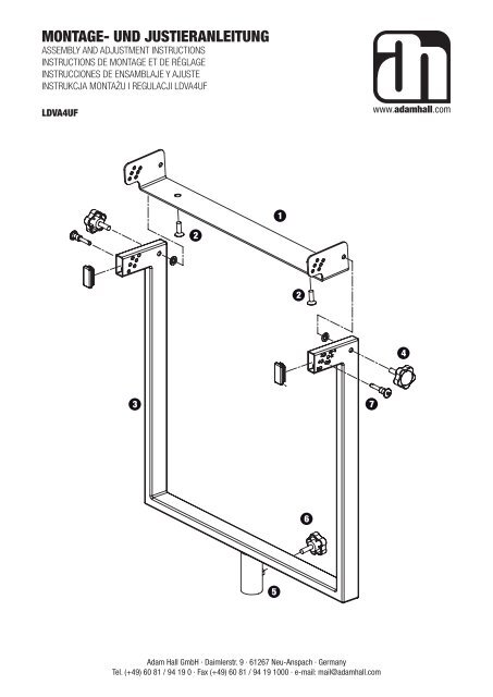
Assembly and Adjustment Instructions for LDVA4UF<br />
Assembly:<br />
Note: Ideally, the system should be assembled with baffle-mounted speakers.<br />
- Fasten the U-frame 1 with both screws 2 to the bottom of the uppermost speaker. When doing so, make certain that the U-frame<br />
is aligned correctly (double row of holes facing forward, see drawing).<br />
- Now up to three additional speakers can be mounted <strong>und</strong>er the speaker with the U-frame.<br />
- Now fasten the U-frame 1 to the frame 3 on both sides with the tommy screws 4 . Tighten the tommy screws only slightly at first.<br />
- Slide the frame with the sleeve 5 onto a compatible stand (tube diameter 35 mm) and fix it in place with the tommy screw 6 .<br />
Adjusting the tilt angle:<br />
- The tilt angle of the speakers can be adjusted within a range of -4° to 6° in increments of 2°. To do this, the correspondingly labelled<br />
hole in the frame is aligned with the associated hole in the U-frame. Insert the locking pins 7 on both sides through this hole<br />
in order to lock the system.<br />
- Once the tilt angle has been adjusted, tighten the tommy screws 4 securely.<br />
<strong>Montage</strong>- <strong>und</strong> <strong>Justieranleitung</strong> für LDVA4UF<br />
<strong>Montage</strong>:<br />
Hinweis: Die <strong>Montage</strong> des Systems sollte am besten mit auf der Schallfront liegenden Lautsprechern erfolgen.<br />
- Den Bügel 1 mit den beiden Schrauben 2 an der Unterseite des obersten Lautsprechers befestigen. Hierbei ist auf die korrekte<br />
Ausrichtung des Bügels zu achten (doppelte Lochreihe nach vorn, siehe Zeichnung).<br />
- Es können nun bis zu drei weitere Lautsprecher unter dem mit dem Bügel versehenen Lautsprecher befestigt werden.<br />
- Nun den Bügel 1 beidseitig mit den Knebelschrauben 3 am Rahmen 4 befestigen. Die Knebelschrauben vorerst nur leicht<br />
anziehen.<br />
- Den Rahmen mit der Hülse 5 auf ein geeignetes Stativ (Rohrdurchmesser 35 mm) stecken <strong>und</strong> mit der Knebelschraube 6 fixieren.<br />
Justieren des Neigungswinkels:<br />
- Der Neigungswinkel der Lautsprecher kann in 2°-Schritten in einem Bereich von -4° bis 6° eingestellt werden. Hierzu wird durch<br />
langsames Neigen der Lautsprecher die entsprechend beschriftete Bohrung im Rahmen deckungsgleich zu der zugehörigen Bohrung<br />
im Bügel ausgerichtet. Die Sicherungsstifte 7 auf beiden Seiten durch diese Bohrung stecken um das System zu arretieren.<br />
- Nach erfolgter Einstellung des Winkels die Knebelschrauben 4 fest anziehen.<br />
Instructions de montage et de réglage pour le LDVA4UF<br />
<strong>Montage</strong> :<br />
Remarque : Dans l‘idéal, le système devrait être assemblé avec des enceintes montées sur baffle.<br />
- Fixez le berceau en U 1 avec les deux vis 2 sur le bas de l‘enceinte supérieure. Ce faisant, vérifiez bien que le berceau en U est<br />
correctement disposé (double rangée de trous dirigée vers l‘avant, voir schéma)<br />
- Désormais, vous pouvez fixer jusqu‘à trois enceintes supplémentaires sous l‘enceinte dans le berceau en U.<br />
- Serrez ensuite le berceau en U 1 sur le châssis, 3 des deux côtés, avec les vis moletées 4 . Ne serrez les vis moletées que<br />
modérément au début.<br />
- Faites glisser le châssis avec la barre 5 dans un pied compatible (diamètre du tube : 35 mm), et fixez-le en place avec la vis<br />
moletée 6 .<br />
Réglage de l‘angle d‘inclinaison:<br />
- L‘angle d‘inclinaison des enceintes est réglable entre -4° et +6°, par pas de 2°. Pour ce faire, il suffit d‘aligner le trou repéré correspondant<br />
du châssis au trou associé dans le berceau en U. Insérez les goupilles de verrouillage 7 des deux côtés du trou, afin de<br />
verrouiller le dispositif.<br />
- Une fois l‘angle d‘inclinaison réglé, serrez fermement les vis moletées 4 .<br />
Adam Hall GmbH · Daimlerstr. 9 · 61267 Neu-Anspach · Germany<br />
Tel. (+49) 60 81 / 94 19 0 · Fax (+49) 60 81 / 94 19 1000 · e-mail: mail@adamhall.com
Instrucciones de ensamblaje y ajuste de LDVA4UF<br />
Ensamblaje:<br />
Nota: Lo ideal es que el sistema esté ensamblado con altavoces montados en bafle.<br />
- Fije el bastidor en U 1 mediante los dos tornillos 2 a la parte inferior del altavoz situado más alto. Asegúrese de que el bastidor<br />
en U esté correctamente alineado, con la doble fila de orificios hacia delante (ver figura).<br />
- Ahora podrá instalar bajo este altavoz hasta 3 altavoces más en el bastidor en U.<br />
- Fije ambos laterales del bastidor en U 1 al bastidor 3 mediante los tornillos de muletilla 4 . De momento, no apriete del todo<br />
estos tornillos.<br />
- Introduzca el bastidor con el tubo 5 en un soporte compatible (diámetro del tubo = 35 mm) y fíjelo con el tornillo de muletilla 6 .<br />
Ajuste del ángulo de inclinación:<br />
- Puede ajustar el ángulo de inclinación de -4° a +6°, en incrementos de 2°. Para realizar este ajuste, alinee el orificio marcado<br />
correspondiente del bastidor con el orificio asociado del bastidor en U. Inserte los pines de bloqueo 4 en ambos laterales por este<br />
orificio para bloquear el sistema.<br />
- Cuando haya ajustado el ángulo de inclinación, apriete fuerte los tornillos de muletilla 7 .<br />
Instrukcja montażu i regulacji LDVA4UF<br />
Montaż:<br />
Uwaga: System powinien zostać złożony z głośników wyposażonych w płytę rezonansową.<br />
- Zamocować ramę U-kształtną 1 obiema śrubami 2 do spodu najwyższego z głośników. Upewnić się, że rama U-kształtna jest<br />
odpowiednio ustawiona (podwójny rząd otworów ustawiony w kierunku przednim, patrz: rysunek).<br />
- Pod głośnikiem zamocowanym na ramie można zamontować do trzech dodatkowych głośników.<br />
- Zamocować ramę U-kształtną obustronnie 1 do ramy głównej 3 za pomocą śrub motylkowych 4 . - Nie dokręcać zbyt mocno.<br />
- Nałożyć ramę główną z obudową 5 na odpowiedni statyw (średnica rury 35 mm) i dokręcić śruby motylkowe. 6 Regulacja kąta<br />
nachylenia:<br />
- Kąt nachylenia głośników można regulować w zakresie od -4° do 6° w skokach 2°. Aby to zrobić, należy odpowiednio ustawić<br />
oznaczone otwory ramy głównej względem otworów ramy U-kształtnej. Włożyć szpilki blokujące 7 po obu stronach przez wskazany<br />
otwór, celem zablokowania konstrukcji.<br />
- Dokręcić odpowiednio śruby motylkowe po ustawieniu kąta nachylenia 4 .<br />
Adam Hall GmbH · Daimlerstr. 9 · 61267 Neu-Anspach · Germany<br />
Tel. (+49) 60 81 / 94 19 0 · Fax (+49) 60 81 / 94 19 1000 · e-mail: mail@adamhall.com