DOC E DOC I - France Automatismes
DOC E DOC I - France Automatismes
DOC E DOC I - France Automatismes

You also want an ePaper? Increase the reach of your titles
YUMPU automatically turns print PDFs into web optimized ePapers that Google loves.
CANCELLI AUTOMATICI<br />
SERIE R | R SERIES | SÉRIE R| BAUREIHE R| SERIE R<br />
FOTOCELLULE<br />
PHOTOCELLS<br />
PHOTOCELLULES<br />
PHOTOZELLEN<br />
FOTOCELULAS<br />
<strong>DOC</strong><br />
Documentazione<br />
Tecnica<br />
42<br />
rev. 4.1<br />
04/2001<br />
© CAME<br />
CANCELLI<br />
AUTOMATICI<br />
119R42<br />
I<br />
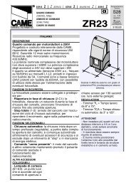
CARATTERISTICHE TECNICHE<br />
La fotocellula non richiede interventi di allineamento<br />
requenza infrarosso: 1000Hz<br />
Portata: 18 m garantiti anche in cattive condizioni atmosferiche<br />
Alimentazione: 12/24V a.c./d.c.<br />
Portata contatti relè: 1A max a 24V<br />
Temperatura di funzionamento: da -15° a +70°C<br />
Assorbimento: 60 mA<br />
Dimensioni <strong>DOC</strong> I: 70x70 mm (contenitore 1: ø60x75 mm)<br />
Dimensioni <strong>DOC</strong> E: 70x70 mm, profondità 34 mm<br />
Materiale contenitori: nylon caricato vetro<br />
Grado di protezione: IP54<br />
A norme UNI 8612<br />
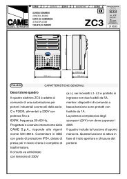
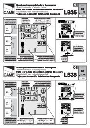
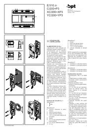
DESCRIZIONE DI MONTAGGIO<br />
A - Murare o fissare i contenitori da incasso sullo stesso asse e alla stessa altezza da terra. Per l’applicazione<br />
dei contenitori sui pilastri in ferro, asportare i 4 supporti per il fissaggio delle viti mantenendo<br />
intatta la battuta del contenitore (<strong>DOC</strong> I).<br />
B - Predisporre i cavi di collegamento all’interno dei contenitori, collegati alle rispettive morsettiere del<br />
trasmettitore TX e del ricevitore RX (Esempi di collegamento)<br />
C - issare i contenitori-circuito al contenitore da incasso (<strong>DOC</strong> I) con le rispettive 4 viti. NB Per l’applicazione<br />
della fotocellula su colonnina <strong>DOC</strong> L, escludere dall’installazione il contenitore da incasso.<br />
D - Applicare lo schermo infrarosso con l’apposita vite e controllare il funzionamento.<br />
GB<br />
TECHNICAL CHARACTERISTICS<br />
The photocells which requires no special alignment<br />
Infrared frequency: 1000Hz<br />
Range: a range of 18 m is guaranteed in any atmospheric conditions<br />
Power supply: 12/24V a.c./d.c.<br />
Relay contact range. 1A max at 24V<br />
Operating temperature: -15° to 70°C<br />
Absorption: 60 mA<br />
<strong>DOC</strong> I dimensions: 70x70 mm (Casing 1: ø60x75 mm)<br />
<strong>DOC</strong> E dimensions: 70x70 mm; depht 34 mm)<br />
Casings material: glass-reinforced nylon<br />
Protection rating: IP54<br />
Conforms to UNI 8612<br />
1 - Contenitore da incasso<br />
2 - Contenitore circuiti ottico/<br />
elettronici<br />
3 - Circuiti ottico/elettronici<br />
4 - Vite fissaggio contenitori<br />
5 - Schermo infrarossi<br />
6 - Vite fissaggio schermo<br />
1 - Casing for embedded<br />
installation<br />
2 - Casing for optical/electronic<br />
circuits<br />
3 - Optical/electronic circuits<br />
4 - ixing screw<br />
5 - Infrared panel<br />
6 - Panel fixing screw<br />
ASSEMBLY DESCRIPTION<br />
A - Attach or embed the casings on the same axis and at the same height. If the casing are fitted to a<br />
steel pillar, remove the four supports which house the screws. Take care not do damage the<br />
support plate (<strong>DOC</strong> I).<br />
B - Insert the connector cables into the casing and connect to the terminals of the<br />
transmitter TX and receiver RX (Examples of connection).<br />
C - asten the circuit box to the casing (<strong>DOC</strong> I) using the four fixing screws. NOTE:<br />
If the photocells are fitted to the <strong>DOC</strong> L columns, the casing 1 should be discarded.<br />
D - it the infrared panel and tighten the fixing screw. Check that the unit functions<br />
correctly.<br />
F<br />
CARACTÉRISTIQUES TECHNIQUES<br />
La photocellule qui ne necressite aucune intervention en ce qui concerne l’allignement<br />
réquence infrarouge: 1000Hz<br />
Portée: la portée garantie est de 18 m, quelles que soient les conditions atmosphériques<br />
Alimentation: 12/24V c.a./c.c.<br />
Portée contacts relais: 1A max a 24V<br />
Température de fonctionnement: des -15° à +70°C<br />
Absorption: 60 mA<br />
Dimensions <strong>DOC</strong> I: 70x70 mm (boîtier 1: ø60x75 mm)<br />
Dimensions <strong>DOC</strong> E: 70x70 mm, profondeur 34 mm<br />
Matériaux des boîtiers: nylon renforcé avec fibre de verre<br />
Degré de protection: IP54<br />
A normes NP 25-362<br />
1 - Boîtier à encastrer<br />
2 - Boîtier pour circuits optique/<br />
électronique<br />
3 - Circuits optique/électronique<br />
4 - Vis de fixation des boîtiers<br />
5 - Ecran infrarouges<br />
6 - Vis de fixation de l’écran<br />
DESCRIPTION DU MONTAGE<br />
A - Sceller ou fixer les boîtiers à encatrer sur le méme axe et à la méme hauteur du sol. Pour appliquer<br />
les boîtiers sur le piller en fer, enlever les 4 supports pour la fixation des vis, en gardant intacte la<br />
surface d’appui du boîtier (<strong>DOC</strong> I).<br />
B - Préparer les cables de connexion à l’intérieur des boîtiers, en les connectant sur les plaques à bornes<br />
clorrespondantes de l’émetteur TX et du récepteur RX (Exemples du branchement)<br />
C - ixer les boîtiers des circuits sur le boîtiers à encastrer (<strong>DOC</strong> I) au moyen des 4 vis correspondantes.<br />
NB Pour l’application de la photocellule sur la colonne <strong>DOC</strong> L, exclure la boîtier à encastrer de l’installatrion.<br />
D - Appliquer l’écran infrarouge au moyen de la vis appropriée et contrôler le fonctionnement.<br />
<strong>DOC</strong> E<br />
D TECHNISCHE DATEN<br />
Die Photozelle, die Keine spezielle ausrichtung erfordert<br />
Infrarotfrequenz: 1000Hz<br />
Reichweite: ohne Ausrichtung garantiert 18 m, bei<br />
jeder Wetterlage<br />
Stromversorgung: 12/24V a.c./d.c<br />
Relaiskontaktleistung: 1A max bei 24V<br />
Betriebstemperatur: zwischen -15° und +70° C<br />
Stromentnahme: 60 mA<br />
<strong>DOC</strong> I Abmessungen: 70 x 70 mm (versenkbarer<br />
Teil Ø 60 mm; Tiefe: 75 mm)<br />
<strong>DOC</strong> E Abmessungen: 70 x 70; Tiefe 34 mm<br />
Material des Gehäuses: glasfaserverstärktes Nylon<br />
Schutzgrad: IP 54<br />
Nach UNI-Norm 8612<br />
MONTAGEBESCHREIBUNG<br />
A - Die Unterputzgehäuse auf derselben Achse und<br />
in derselben Bodenhöhe befestigen oder einmauern.<br />
Bei Anbringung der Gehäuse auf Stahlpfeilern, die<br />
4 Schraubenhalterungen entfernen, den<br />
Gehäuseanschlag unversehrt lassen<br />
(<strong>DOC</strong> I).<br />
B - Die Anschlußkabel im lnneren des Gehäuse<br />
vorbereiten und an die entsprechenden Klemmbretter<br />
des Senders TX und des Empfängers RX anschließen<br />
(Anschlußbeispiele).<br />
C - Die Stromkreisgehäuse mit den 4 entspechenden<br />
Schrauben am Unterputzgehäuse (<strong>DOC</strong> I) befestigen.<br />
Achtung: Beim Einbau der Photozelle in<br />
Standsäulen <strong>DOC</strong> L das Unterputzgehäuse von der<br />
Montage ausschließen.<br />
D - Den Infrarotschirm mit der entsprechenden<br />
Schraube anschrauben und nochmals eine<br />
Betriebskontrolle durchführen.<br />
1 - Unterpuntzgehäuse<br />
2 - Gehäuse für optisch-elektronische Shaltkreise<br />
3 - Optisch-elektronische Shaltkreise<br />
4 - Gehäusebefestigungsschraube<br />
5 - Infrarotschirm<br />
6 - Schraube Infrarotschirmbefestigung<br />
<strong>DOC</strong> I<br />
E CARACTERISTICAS TÉCNICAS<br />
La fotocélula que no require alineamiento<br />
requencia infrarrojo: 1000 Hz<br />
Alcance: se garantizan 18 m con cualquier condición<br />
atmosférica<br />
Alimentación: 12/24V a.c./d.c.<br />
Alcance conctatos relés: 1A máx a 24V<br />
Temperatura de funcionamiento: de -15° a +70° C<br />
Absorbencia: 60 mA<br />
Dimensiones <strong>DOC</strong> I: 70 x 70 mm (parte empotrable Ø<br />
60 mm; profundidad 75 mm)<br />
Dimensiones <strong>DOC</strong> E: 70 x 70 mm; profundidad 34 mm<br />
Materiales de las cajas: nylon reforzado con vidrio<br />
Grado de protección: IP 54<br />
A las normas UNI 8612<br />
DESCRIPCION DEL MONTAJE<br />
A - Empotrar o fijar los contenedores empotrables a<br />
lo largo del mismo eje y a la misma altura del suelo.<br />
Para la aplicación de los contenedores en el pilar de<br />
hierro, quitar los 4 soportes para la sujeción de los<br />
tornillos sin danar la placa de soporte del<br />
contenedor (<strong>DOC</strong> I).<br />
B - Predisponer los cables de conexión en el interior<br />
de los contenedores, conectarlos a las terminales<br />
relatives del transmisor TX y del recptor RX (Ejemplos<br />
de conexión).<br />
C - ijar los contenedores-circuitos en el contenedor<br />
empotrable (<strong>DOC</strong> I), con los tornillos especificos.<br />
Nota: Para la aplicación de la fotocélula en la<br />
columna <strong>DOC</strong> L, no incorporar en la instalación<br />
el contenedor empotrable.<br />
D - Aplicar la pantalla infrarroja mediante el<br />
tornillo especifico y comprobar el funcionamento.<br />
1 - Contenedor empotrable<br />
2 - Contenedor circuitos óptico/electrónicos<br />
3 - Circuitos óptico/electrónicos<br />
4 - Tornillo de sujeción contenedores<br />
5 - Pantalla infrarrojos<br />
6 - Tornillo de sujeción pantalla
I<br />
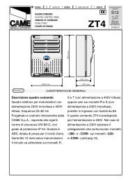
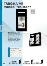
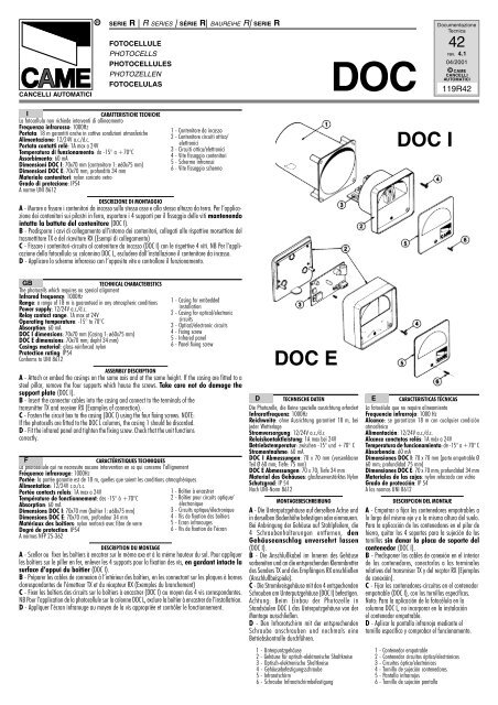
COLLEGAMENTO<br />
DI UNA COPPIA DI FOTOCELLULE<br />
(fig. 1)<br />
- Selezionare l'alimentazione con i<br />
Dip 2 (Fig. 2).<br />
- Procedere al collegamento elettrico<br />
(Fig. 1 e 3).<br />
GB<br />
CONNECTION<br />
OF ONE PAIR OF PHOTOCELLS<br />
(fig. 1)<br />
- Select the desired voltage using<br />
Dip 2 (Fig. 2).<br />
- Connect up the wiring (Fig. 1<br />
and 3).<br />
F<br />
BRANCHEMENT D'UNE<br />
COUPLE DE PHOTOCELLULES<br />
(fig. 1)<br />
- Sélectionner l'alimentation avec<br />
le Dip 2 (Fig. 2).<br />
- Procéder au branchement<br />
électrique (Fig. 1 et 3).<br />
D<br />
ANSCHLUSS VON<br />
EINES PHOTOZELLENPAARS<br />
(Abb. 1)<br />
- Die Stromversorgung an den Dip-<br />
Schaltern 2 auswählen (Abb. 2).<br />
- Den Stromanschluß durchführen<br />
(Abb. 1 u. 3).<br />
E<br />
CONEXIÓN DE<br />
UNA PAREJA DE FOTOCÉLULAS<br />
(fig. 1)<br />
- Seleccionar la alimentación con<br />
el dip 2 (Fig. 2).<br />
- Proceder a la conexión eléctrica<br />
(Fig. 1 y 3).<br />
COLLEGAMENTO DI DUE<br />
COPPIE DI FOTOCELLULE<br />
(fig. 4)<br />
Come il precedente, con l'avvertenza<br />
d'installare alternativamente<br />
trasmettitore (TX) e ricevitore<br />
(RX).<br />
Inoltre, solo nel caso di alimentazione<br />
a.c., invertire le polarità<br />
tra coppia e coppia di fotocellule,<br />
per evitare sovrapposizioni di<br />
segnali, e commutare i Dip 1 in<br />
ON (Fig. 5).<br />
CONNECTION OF TWO<br />
PAIRS OF PHOTOCELLS<br />
(Fig. 4)<br />
Just like beware, but installing<br />
the transmitter (TX) and the<br />
receiver (RX) alternately.<br />
And, if the photocells are<br />
connected to an a.c. power<br />
supply, reverse the polarity with<br />
respect to the first pair of<br />
photocells in order to avoid<br />
signal overlap. In this case,<br />
position Dip 1 in ON (fig. 5).<br />
BRANCHEMENT DE DEUX<br />
COUPLES DE PHOTOCELLULES<br />
(Fig. 4)<br />
Procéder comme ei-dessus, en<br />
ayant cependant soin d'installer<br />
alternativement un émetteur (TX)<br />
et un récepteur (RX).<br />
De plus, en cas d'alimentation<br />
a.c., invertir les polarités entre<br />
les couples de photocellules, afin<br />
d'éviter des superpositions de<br />
signaux, et positionner le Dip 1<br />
en ON (fig. 5).<br />
ANSCHLUSS VON ZWEI<br />
PHOTOZELLENPAAREN<br />
(Abb. 4)<br />
Wie oben beschrieben vorgehen.<br />
Der Sender (TX) und der Empfänger<br />
(RX) sollten dabei auf gegenüberliegenden<br />
Seiten installiert werden.<br />
Bei Versorgung mit Wechselstrom<br />
sollte die Polarität zwischen den<br />
beiden Fotozellenpaaren invertiert<br />
werden, um eine Signalüberlagerung<br />
zu vermeiden. Außerdem<br />
die Dip-Schalter 1 auf ON stellen<br />
(Abb. 5)<br />
CONEXIÓN DE DOS<br />
PAREJAS DE FOTOCÉLULAS<br />
(fig. 4)<br />
Como el precedente, con la<br />
advertencia de instalar alternativamente<br />
el transmisor TX y el<br />
receptor RX.<br />
Además, sólo en el caso de<br />
alimentación a.c., invertir la<br />
polaridad entre pareja de<br />
fotocélulas, para evitar<br />
supurposiciones de señales, y<br />
activar el dip 1 in ON (fig. 5).<br />
12<br />
<strong>DOC</strong>-I<br />
1 2<br />
+ - N O C N C<br />
1 2<br />
<strong>DOC</strong>-E<br />
+ - N O C N C<br />
1 2<br />
Fig. 2<br />
dip 2 OFF<br />
1 2<br />
24V<br />
dip 2 ON<br />
1 2<br />
12V<br />
Fig. 1<br />
1 2<br />
RX<br />
Fig. 3<br />
ESEMPI DI COLLEGAMENTO<br />
(con quadro comando CAME)<br />
EXAMPLES OF CONNECTION<br />
(with CAME control panel)<br />
EXEMPLES DE BRANCHEMENT<br />
(avec TABLEAU de commande CAME)<br />
ANSCHLUSSBEISPIELE<br />
(mit CAME-Steuerung)<br />
EJEMPLOS DE CONEXIÓN<br />
(con cuadro de mando CAME)<br />
1 2<br />
+ -<br />
TX<br />
RX<br />
+ -<br />
NO C NC<br />
TX<br />
Stop parziale<br />
Partial stop<br />
Stop partiel<br />
Teilstop<br />
Stop parcial<br />
0 1<br />
(10 11)<br />
2 C2<br />
(2 CX)<br />
Fig. 4<br />
1 2<br />
RX<br />
Alimentazione A.C.<br />
A.C. power supply<br />
Alimentation A.C.<br />
Stromversorg A.C.<br />
Alimentación A.C.<br />
Stop totale<br />
Total stop<br />
Arrêt total<br />
Totalstop<br />
Stop total<br />
Richiusura durante l'apertura<br />
Re-closing during opening<br />
Réfermeture pendant<br />
l'ouverture<br />
Erneutes Schließen beim Öffnen<br />
Recierre durante la fase de<br />
apertura<br />
0 1<br />
(10 11)<br />
0 1<br />
(10 11)<br />
1 2<br />
2 C2<br />
(2 CX)<br />
TX<br />
1 2<br />
TX<br />
Riapertura durante la chiusura<br />
Re-opening during closure<br />
Réouverture pendant la<br />
fermeture<br />
Erneutes Öffnen beim Schließen<br />
Reapertura durante la fase de<br />
cierre<br />
0 1<br />
(10 11)<br />
2 C<br />
(2 C1)<br />
1 2 1 2<br />
RX<br />
Fig. 5<br />
UNA COPPIA DI FOTOCELLULE<br />
ONE PAIR OF PHOTOCELLS<br />
UNE COUPLE DE PHOTOCELLULES<br />
EINES PHOTOZELLEN-PAARS<br />
UNA PAREJA DE FOTOCÉLULAS<br />
dip 1 OFF<br />
1 2<br />
dip 1 ON DUE COPPIE DI FOTOCELLULE<br />
TWO PAIRS OF PHOTOCELLS<br />
DEUX COUPLES DE PHOTOCELLULES<br />
ZWEI PHOTOZELLEN-PAAREN<br />
1 2 DOS PAREJAS DE FOTOCÉLULAS