Create successful ePaper yourself
Turn your PDF publications into a flip-book with our unique Google optimized e-Paper software.
3 Electrical Installation<br />
• Control Circuit Terminals<br />
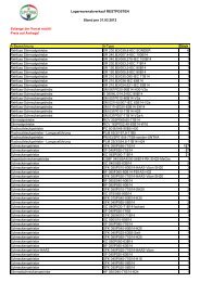
The figure below shows the control circuit terminal arrangement. The drive is equipped with screwless terminals.<br />
S2<br />
S1<br />
R+ R- S+ S- IG<br />
S3<br />
P1 P2 PC A1 A2 +V <strong>AC</strong> AM <strong>AC</strong> MP<br />
S1 S2 S3 S4 S5 S6 SC HC H1 H2 RP<br />
MA MB MC<br />
Use a straght-edge screwdriver<br />
with a blade width of max 2.5 mm<br />
and a thickness of max 0.6 mm to<br />
release the terminals<br />
There are three DIP switches, S1 to S3, located on the terminal board<br />
SW1<br />
SW2<br />
SW3<br />
Switches analog input A2 between voltage and current input<br />
Enables or disables the internal RS422/485 comm. port terminal resistance.<br />
Used to select sourcing (PNP)/sinking (NPN, default) mode for the digital inputs (PNP requires external 24 Vdc power supply)<br />
• Control Circuit Terminal Functions<br />
<strong>Type</strong> No. Terminal Name (Signal) Function (Signal Level), Default Setting<br />
Multi-Function<br />
Digital Inputs<br />
Multi-Function<br />
Analog/ Pulse<br />
Inputs<br />
<strong>Drive</strong><br />
Disable Inputs<br />
Multi-Function<br />
Relay Output<br />
Multi-Function PHC<br />
Output<br />
Monitor Output<br />
MEMOBUS/<br />
Communication<br />
Operator/ PC<br />
Communication<br />
S1<br />
to<br />
S6<br />
Multi-function digital input 1 to 6<br />
SC Multi-function input common Sequence common<br />
Photocoupler inputs, 24 Vdc, 8 mA<br />
Note: <strong>Drive</strong> preset to sinking mode (NPN). When using source mode, set DIP switch<br />
S3 to “SOURCE” and use an external 24 Vdc (±10%) power supply.<br />
RP Pulse train input<br />
Response frequency: 0.5 to 32 kHz, Duty: 30 to 70%, High: 3.5 to 13.2 V, Low: 0.0<br />
to 0.8 V, input impedance: 3 k)<br />
+V Analog input power supply +10.5 V (max allowable current 20 mA)<br />
A1 Multi-function analog input 1 0 to +10 Vdc (20 k) resolution 1/1000<br />
A2 Multi-function analog input 2<br />
0/4 to 20 mA (250 ) resolution: 1/500 (A2 only)<br />
<strong>AC</strong> Frequency reference common 0 V<br />
HC <strong>Drive</strong> Disable Input common +24 V (max 10 mA allowed)<br />
H1 <strong>Drive</strong> Disable Input 1 One or both open: <strong>Drive</strong> output disabled (time from input open to drive output<br />
H2 <strong>Drive</strong> Disable Input 2<br />
switch off is less than 1 ms)<br />
Both Closed: Normal operation<br />
MA N.O. (fault) Digital relay output<br />
MB N.C. output (fault)<br />
30 Vdc, 10 mA to 1 A<br />
MC Digital output common<br />
250 Vac, 10 mA to 1 A<br />
P1 Photocoupler output 1<br />
P2 Photocoupler output 2<br />
PC Photocoupler output common<br />
Digital photocoupler output<br />
48 Vdc, 2 to 50 mA<br />
MP Pulse train output 32 kHz (max)<br />
AM Analog monitor output 0 to 10 Vdc (2 mA or less), Resolution: 1/1000 (10 bit)<br />
<strong>AC</strong> Monitor common 0 V<br />
R+ Communications input (+)<br />
R– Communications input (–)<br />
S+ Communications output (+)<br />
S– Communications output (–)<br />
RJ45<br />
Communication port to Digital Operator<br />
or PC<br />
MEMOBUS/Modbus communication.:<br />
RS-485 or RS-422, 115.2 kbps (max)<br />
RS232: PC connection via JVOP-181 (USB Copy Unit), Digital Operators JVOP-180<br />
(LCD) or JVOP-182 (LED). Other device connection may damage the drive or the<br />
external device.Variant CIMR-...-0080 only on the drive. Variant CIMR-...-0081 with<br />
external RJ45 connector.<br />
NOTICE: The terminals HC, H1, H2 can be used to disable the drive output. Other than in <strong>V1000</strong> standard drives they can NOT be used to perform safe stop according to<br />
EN60204-1 (Function is in preparation. Contact your sales representative or <strong>YASKAWA</strong> for details).<br />
NOTICE: The wiring length to the terminals HC, H1 and H2 should not exceed 30 m.<br />
<strong>YASKAWA</strong> Europe TOMP_C710606_75A <strong>V1000</strong> <strong>IP66</strong> - Quick Start Guide EN 15