Create successful ePaper yourself
Turn your PDF publications into a flip-book with our unique Google optimized e-Paper software.
3 Electrical Installation<br />
3 Electrical Installation<br />
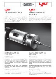
The figure below shows the main and control circuit wiring.<br />
DC reactor<br />
(option)<br />
Link<br />
Thermal<br />
relay<br />
Braking<br />
resistor<br />
(opt)<br />
Power<br />
Supply<br />
L1<br />
L2<br />
L3<br />
Main<br />
Switch<br />
Fuses<br />
Filter<br />
L1<br />
L2<br />
L3 <br />
Forward/Stop<br />
Reverse/Stop<br />
External Fault<br />
S1<br />
S2<br />
S3<br />
<br />
+2 +1 B1 B2<br />
<strong>V1000</strong> <strong>IP66</strong><br />
U/T1<br />
V/T2<br />
W/T3<br />
Ground<br />
Shielded<br />
Cable<br />
U<br />
V<br />
W<br />
M<br />
Fault Reset<br />
S4<br />
Multi-speed 1<br />
S5<br />
Multi-function<br />
digital inputs<br />
(default setting)<br />
Multi-speed 2<br />
2 kΩ<br />
S6<br />
SC<br />
RP<br />
+V<br />
A1<br />
A2<br />
<strong>AC</strong><br />
DIP<br />
switch S3<br />
+24 V 8 mA<br />
SINK<br />
SOURCE<br />
24 V<br />
0V<br />
Shielded ground<br />
terminal<br />
Pulse Input<br />
(max. 32kHz)<br />
Analog input power supply<br />
+10.5 Vdc, max. 20 mA<br />
Multi-function analog input 1<br />
0 to 10 V (20 kΩ)<br />
Multi-function analog input 2<br />
0 to 10 V (20 kΩ) or<br />
0/4 to 20 mA (250 Ω)<br />
MA<br />
MB<br />
MC<br />
P1<br />
P2<br />
PC<br />
MP<br />
AM<br />
<strong>AC</strong><br />
Fault<br />
During run<br />
Multi-function relay output<br />
250 Vac / 30 Vdc (10 mA to 1A)<br />
(default setting)<br />
Frequency agree<br />
Photocoupler<br />
common<br />
Pulse train output<br />
(max. 32 kHz)<br />
(Output frequency)<br />
Analog output<br />
0 to +10 Vdc (2mA)<br />
(Output frequency)<br />
Multi-function<br />
photocoupler<br />
output<br />
48 Vdc, 2 to 50 mA<br />
(default setting)<br />
Monitor outputs<br />
(default setting)<br />
Multi-function pulse / analog inputs<br />
(default: frequency reference)<br />
Terminal resistance<br />
(120 Ω, 1/2 W)<br />
R+<br />
<strong>Drive</strong> Disable<br />
inputs <br />
H2<br />
H1<br />
R−<br />
S+<br />
S−<br />
Memobus comm.<br />
RS-485/422<br />
max. 115 kbps<br />
HC<br />
IG<br />
Symbols:<br />
Use twisted pair cables.<br />
Use shielded twisted pair cables.<br />
Indicates the <strong>IP66</strong> enclosure.<br />
Indicates a main circuit terminal.<br />
Indicates a control circuit terminal.<br />
Single-phase units do not have a L3 terminal.<br />
These terminals can be used to disable the drive output. Other than in <strong>V1000</strong> standard drives they can NOT be used to perform safe stop according to EN60204-1 (Function<br />
is in preparation. Contact your sales representative or <strong>YASKAWA</strong> for details).<br />
EN 12<br />
<strong>YASKAWA</strong> Europe TOMP_C710606_75A <strong>V1000</strong> <strong>IP66</strong> - Quick Start Guide