Manual de instalación - Golmar
Manual de instalación - Golmar
Manual de instalación - Golmar

You also want an ePaper? Increase the reach of your titles
YUMPU automatically turns print PDFs into web optimized ePapers that Google loves.
CONFORMIDAD/COMPLIANCE/CONFORMITÉ151<br />
Este producto es conforme con las disposiciones <strong>de</strong> las Directivas Europeas<br />
aplicables respecto a la Seguridad Eléctrica 2006/95/CEE y la Compatibilidad<br />
Electromagnética 2004/108/CEE, así como con la ampliación en la Directiva <strong>de</strong>l<br />
Marcado CE 93/68/CEE.<br />
This product meets the essentials requirements of applicable European<br />
Directives regarding Electrical Safety 2006/95/CEE, Electromagnetic Compatibility<br />
2004/108/ECC, and as amen<strong>de</strong>d for CE Marking 93/68/ECC.<br />
NOTA: El funcionamiento <strong>de</strong> este equipo está sujeto a las siguientes<br />
condiciones:<br />
(1) Este dispositivo no pue<strong>de</strong> provocar interferencias dañinas, y (2)<br />
<strong>de</strong>be aceptar cualquier interferencia recibida, incluyendo las que<br />
pue<strong>de</strong>n provocar un funcionamiento no <strong>de</strong>seado.<br />
NOTE: Operation is subject to the following conditions:<br />
(1) This <strong>de</strong>vice may not cause harmful interference, and (2) this <strong>de</strong>vice<br />
must accept any received interference, including the ones that may<br />
cause un<strong>de</strong>sired operation.<br />
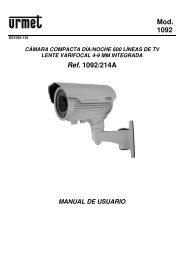
Portero Electrónico<br />
y Vi<strong>de</strong>oportero<br />
instalación digital<br />
(Una o varias puertas<br />
<strong>de</strong> acceso /<br />
Placa general)<br />
Stadio Plus<br />
T500SE ML<br />
rev.0112<br />
golmar@golmar.es<br />
www.golmar.es<br />
manual <strong>de</strong> instalación<br />
version français (page 48)<br />
english version (page 96)<br />
<strong>Golmar</strong> se reserva el <strong>de</strong>recho a cualquier modificación sin previo aviso.<br />
<strong>Golmar</strong> se réserve le droit <strong>de</strong> toute modification sans préavis.<br />
<strong>Golmar</strong> reserves the right to make any modifications without prior notice.<br />
Cod. 50124509
INTRODUCCIÓN<br />
1<br />
2<br />
PRECAUCIONES DE SEGURIDAD<br />
Ante todo le agra<strong>de</strong>cemos y felicitamos por la adquisición <strong>de</strong> este producto fabricado por <strong>Golmar</strong>.<br />
Nuestro compromiso por conseguir la satisfacción <strong>de</strong> clientes como usted queda manifiesto por nuestra<br />
certificación ISO-9001 y por la fabricación <strong>de</strong> productos como el que acaba <strong>de</strong> adquirir.<br />
La avanzada tecnología <strong>de</strong> su interior y un estricto control <strong>de</strong> calidad harán que, clientes y usuarios<br />
disfruten <strong>de</strong> las innumerables prestaciones que este equipo ofrece. Para sacar el mayor provecho <strong>de</strong> las<br />
mismas y conseguir un correcto funcionamiento <strong>de</strong>s<strong>de</strong> el primer día, rogamos lea <strong>de</strong>tenidamente este<br />
manual <strong>de</strong> instrucciones.<br />
ÍNDICE<br />
Introducción .........................................1<br />
Índice ..................................................1<br />
Consejos para la puesta en marcha .........1<br />
Precauciones <strong>de</strong> seguridad .....................2<br />
Características <strong>de</strong>l sistema.................2 a 3<br />
Funcionamiento <strong>de</strong>l sistema....................3<br />
Instalación <strong>de</strong> la placa .............................<br />
Descripción........................................4<br />
Ubicación <strong>de</strong> la caja <strong>de</strong> empotrar.....5 a 6<br />
Montaje <strong>de</strong> los módulos.......................6<br />
Colocación <strong>de</strong> circuitos electrónicos .....7<br />
Sujeción <strong>de</strong> la placa ............................8<br />
Colocación etiqueta visor informativo....8<br />
Cableado <strong>de</strong> los pulsadores..........9 a 10<br />
Códigos <strong>de</strong> los pulsadores .................11<br />
Configuración circuito EL500SE .....12 a 13<br />
Programación (placa general)......14 a16<br />
Conexión visor <strong>de</strong>l canal ocupado ......16<br />
Cableado <strong>de</strong> las lamparitas................17<br />
Ajustes finales y cierre <strong>de</strong> la placa ........17<br />
Instalación <strong>de</strong>l alimentador ..................18<br />
Instalación <strong>de</strong>l abrepuertas...................18<br />
Monitor Platea/Tekna Plus ........................<br />
Descripción......................................19<br />
Pulsadores <strong>de</strong> función........................20<br />
Módulo EL562 .................................21<br />
Resistencia final <strong>de</strong> línea ....................21<br />
Cambio <strong>de</strong> carátula ..........................21<br />
Regleta <strong>de</strong> conexión ..........................22<br />
Sujeción <strong>de</strong>l monitor..........................23<br />
Programación ..................................24<br />
Teléfono T-740 Plus .................................<br />
Descripción...............................25 a 26<br />
Pulsadores <strong>de</strong> función........................26<br />
Sujeción <strong>de</strong>l teléfono .........................27<br />
Programación ..................................28<br />
Esquemas <strong>de</strong> instalación ..........................<br />
Vi<strong>de</strong>oportero con coaxial............29 a 30<br />
Vi<strong>de</strong>oportero sin coaxial .............31 a 32<br />
Portero electrónico.....................33 a 34<br />
Vi<strong>de</strong>oportero (placa general).......35 a 38<br />
Portero elec. (placa general)........39 a 40<br />
Conexión <strong>de</strong> un abrepuertas c.a. ........41<br />
Enlace <strong>de</strong> varios alimentadores...........41<br />
Conexionados opcionales.............42 a 46<br />
Solución <strong>de</strong> averías..............................47<br />
Notas .......................................144-150<br />
Conformidad....................................151<br />
CONSEJOS PARA LA PUESTA EN MARCHA<br />
O No apretar excesivamente los tornillos <strong>de</strong> la regleta <strong>de</strong>l alimentador.<br />
O Toda la instalación <strong>de</strong>be viajar alejada al menos a 40 cm. <strong>de</strong> cualquier otra instalación.<br />
O Antes <strong>de</strong> conectar el equipo, verificar el conexionado entre placa, distribuidores, monitores,<br />
teléfonos y el conexionado <strong>de</strong>l alimentador. Siga en todo momento las instrucciones <strong>de</strong> este manual.<br />
O Al poner en marcha el equipo por primera vez, o tras una modificación, el sistema permanecerá<br />
inactivo unos 30 segundos <strong>de</strong>bido al tiempo <strong>de</strong> arranque.<br />
O En equipos con cable coaxial, utilice siempre cable RG-59 B/U MIL C-17 o RG-11, (ver pág. 30).<br />
No utilice nunca cable coaxial <strong>de</strong> antena. En instalaciones <strong>de</strong> hasta 100m pue<strong>de</strong> utilizar el<br />
cable <strong>Golmar</strong> RAP-5130, que incluye todos los conductores necesarios para la instalación.<br />
O Cuando se instale o modifique los equipos, hacerlo sin alimentación.<br />
O La instalación y manipulación <strong>de</strong> estos equipos <strong>de</strong>ben ser realizadas por personal autorizado.<br />
O Toda la instalación <strong>de</strong>be viajar alejada al menos a 40 cm. <strong>de</strong> cualquier otra instalación.<br />
O En el alimentador:<br />
wNo apretar excesivamente los tornillos <strong>de</strong> la regleta.<br />
wInstale el alimentador en un lugar seco y protegido sin riesgo <strong>de</strong> goteo o proyecciones <strong>de</strong> agua.<br />
wEvite emplazamientos cercanos a fuentes <strong>de</strong> calor, húmedos o polvorientos.<br />
wNo bloquee las ranuras <strong>de</strong> ventilación para que pueda circular el aire libremente.<br />
wPara evitar daños, el alimentador tiene que estar firmemente anclado.<br />
wPara evitar choque eléctrico, no quite la tapa ni manipule los cables conectados a los terminales.<br />
O En el monitor, teléfonos y distribuidores:<br />
wNo apretar excesivamente los tornillos <strong>de</strong> la regleta.<br />
wInstale los equipos en un lugar seco y protegido sin riesgo <strong>de</strong> goteo o proyecciones <strong>de</strong> agua.<br />
wEvite emplazamientos cercanos a fuentes <strong>de</strong> calor, húmedos, polvorientos o con mucho humo.<br />
wNo bloquee las ranuras <strong>de</strong> ventilación para que pueda circular el aire libremente.<br />
O Recuer<strong>de</strong>, la instalación y manipulación <strong>de</strong> estos equipos <strong>de</strong>ben ser realizados por personal<br />
autorizado y en ausencia <strong>de</strong> corriente eléctrica.<br />
O Siga en todo momento las instrucciones <strong>de</strong> este manual.<br />
CARACTERÍSTICAS DEL SISTEMA<br />
O Equipos microprocesados con instalación simplificada (bus sin hilos <strong>de</strong> llamada):<br />
wPortero electrónico con instalación <strong>de</strong> 4 hilos comunes.<br />
wVi<strong>de</strong>oportero con instalación <strong>de</strong> 3 hilos comunes más cable coaxial.<br />
wVi<strong>de</strong>oportero con instalación <strong>de</strong> 4 hilos comunes más par trenzado.<br />
O Circuito microprocesador EL500SE con dos modos <strong>de</strong> funcionamiento (EL500 ó EL501).<br />
O Ilimitado número <strong>de</strong> placas (accesos) sin necesidad <strong>de</strong> unida<strong>de</strong>s <strong>de</strong> conmutación.<br />
O Hasta 120 monitores/teléfonos por edificio o canal.<br />
O Placas generales (modo EL501): Hasta 120 monitores/teléfonos, distribuidos en máx. 120 edificios.<br />
O Módulo EL560 para transmisión <strong>de</strong> ví<strong>de</strong>o através <strong>de</strong> par trenzado, integrado en el circuito EL500SE.<br />
O Resistencia <strong>de</strong> comunicaciones para el sistema UNO ó PLUS, integrado en el circuito EL500SE.<br />
O Tonos telefónicos para confirmación <strong>de</strong> llamada y canal ocupado.<br />
O Apertura <strong>de</strong> puerta temporizada durante 3 segundos.<br />
O Entrada para pulsador exterior <strong>de</strong> apertura <strong>de</strong> puerta (temporizable a 3 ó 15 seg.).<br />
O Abrepuertas <strong>de</strong> corriente continua o alterna accionado mediante relé.<br />
O Hasta 13 monitores o teléfonos en cada vivienda, (ver página 46):<br />
wHasta 3 monitores o teléfonos (sin alimentación adicional).<br />
er<br />
wDel 4º al 8º monitor/teléfono (1 alimentador adicional FA-Plus/C, montar en armario técnico).<br />
wDel 9º al 13º monitor/teléfono (2º alimentador adicional FA-Plus/C, montar en armario técnico).<br />
O Prestaciones comunes para los monitores Platea/Tekna Plus y los teléfonos T-740 Plus:<br />
wSecreto total <strong>de</strong> conversación.<br />
wIntercomunicación entre dos equipos <strong>de</strong>ntro <strong>de</strong> la misma vivienda. (Sólo un equipo secundario<br />
configurado con intercomunicación).<br />
wEntrada para llamada <strong>de</strong>s<strong>de</strong> la puerta interior <strong>de</strong> la vivienda.<br />
wSalida a sonería auxiliar.<br />
wLlamada a central <strong>de</strong> conserjería principal.<br />
wLlamada <strong>de</strong> pánico a las centrales <strong>de</strong> conserjería.<br />
wVarios tonos <strong>de</strong> llamada que permiten distinguir su proce<strong>de</strong>ncia: placa principal, placa<br />
secundaria, intercomunicación, puerta interior <strong>de</strong> la vivienda, ...<br />
Continúa
CARACTERÍSTICAS DEL SISTEMA<br />
3<br />
4<br />
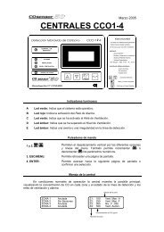
DESCRIPCIÓN DE LA PLACA<br />
Viene <strong>de</strong> la página anterior<br />
OEn los teléfonos T-740 Plus, a<strong>de</strong>más <strong>de</strong> las prestaciones anteriores:<br />
wRegulador <strong>de</strong> volumen <strong>de</strong> llamada (máximo, medio y <strong>de</strong>sconexión).<br />
wEntrada para pulsador exterior abrepuertas.<br />
wPermite una <strong>de</strong> estas funciones a la vez, configurable con el microinterruptor Sw1 (ver pág. 26):<br />
wFunción "Autoencendido".<br />
wSalida activación relé auxiliar (18Vcc/0,5 A máximo).<br />
wLlamada a central <strong>de</strong> conserjería secundaria.<br />
wIntercomunicación entre dos equipos <strong>de</strong>ntro <strong>de</strong> la misma vivienda.<br />
OEn los monitores Platea/Tekna Plus, a<strong>de</strong>más <strong>de</strong> las prestaciones comunes:<br />
wRegulador <strong>de</strong> volumen <strong>de</strong> llamada (máximo, medio y mínimo).<br />
wFunción "Autoencendido".<br />
wFunción "Autoespía" sin ocupar canal.<br />
wLlamada a central <strong>de</strong> conserjería secundaria.<br />
wActivación <strong>de</strong> dos funciones auxiliares: segunda cámara, luces <strong>de</strong> cortesía, ...<br />
wMonitor B/N y Color.<br />
wRegulación <strong>de</strong> brillo y contraste (color en caso <strong>de</strong> monitor en color).<br />
FUNCIONAMIENTO DEL SISTEMA<br />
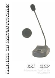
Cabezales<br />
600<br />
*<br />
Módulos rejilla<br />
1xxx<br />
2xxx<br />
Visor informativo<br />
Modulo pulsadores<br />
3xxx<br />
Descripción <strong>de</strong> la placa.<br />
Cajas <strong>de</strong> empotrar CE-6xx<br />
O Para realizar la llamada, el visitante <strong>de</strong>berá presionar el pulsador correspondiente a la vivienda con<br />
la que <strong>de</strong>sea establecer comunicación, unos tonos acústicos advertirán <strong>de</strong> que la llamada se está<br />
realizando. En este instante, el monitor (teléfono) <strong>de</strong> la vivienda recibe la llamada. Si se ha<br />
presionado por equivocación el pulsador <strong>de</strong> otra vivienda, pulsar sobre el que corresponda con la<br />
vivienda <strong>de</strong>seada, cancelando así la primera llamada.<br />
O En equipos con varias puertas <strong>de</strong> acceso, la(s) otra(s) placa(s) quedará(n) automáticamente<br />
<strong>de</strong>sconectada(s), si otro visitante <strong>de</strong>sea llamar, unos tonos telefónicos le advertirán <strong>de</strong> que el canal<br />
está ocupado y el indicador <strong>de</strong> canal ocupado <strong>de</strong>l visor se iluminará (si existe).<br />
O Placas generales (modo EL501): Si la llamada se está realizando <strong>de</strong>s<strong>de</strong> la placa general, la placa<br />
interior <strong>de</strong>l edificio llamado y las otras posibles placas generales quedarán automáticamente<br />
<strong>de</strong>sconectadas, si otro visitante intenta llamar <strong>de</strong>s<strong>de</strong> una placa interior ocupada o <strong>de</strong>s<strong>de</strong> otra placa<br />
general, unos tonos telefónicos le advertirán <strong>de</strong> que el canal está ocupado y el indicador <strong>de</strong> canal<br />
ocupado <strong>de</strong>l visor parpa<strong>de</strong>ará (en la placa general). Las placas <strong>de</strong> los otros edificios interiores<br />
quedarán libres <strong>de</strong> ser usadas.<br />
O Placas generales (modo EL501): En el caso <strong>de</strong> que la llamada se realice <strong>de</strong>s<strong>de</strong> una placa interior, el<br />
resto <strong>de</strong> placas interiores quedarán libres <strong>de</strong> ser usadas. Des<strong>de</strong> las placas generales sólo se podrán<br />
realizar llamadas a los edificios interiores cuyas placas no se encuentren en uso, si se intenta realizar<br />
una llamada a una placa interior ocupada, unos tonos telefónicos le advertirán <strong>de</strong> que el canal está<br />
ocupado y el indicador <strong>de</strong> canal ocupado <strong>de</strong>l visor parpa<strong>de</strong>ará.<br />
O La llamada tiene una duración <strong>de</strong> 45 segundos, apareciendo la imagen en el monitor principal unos<br />
3 segundos <strong>de</strong>spués <strong>de</strong> recibir la llamada sin que el visitante lo perciba. Para visualizar la imagen en<br />
un monitor secundario presionar el pulsador , <strong>de</strong>sapareciendo la imagen <strong>de</strong>l monitor que la<br />
estaba visualizando. Si la llamada no es atendida antes <strong>de</strong> 45 segundos, el canal quedará libre.<br />
O Para establecer comunicación, <strong>de</strong>scolgar el auricular <strong>de</strong>l (monitor) teléfono.<br />
O La comunicación tendrá una duración <strong>de</strong> un minuto y medio o hasta colgar el auricular. Finalizada la<br />
comunicación, el canal quedará libre.<br />
O Si se <strong>de</strong>sea abrir la puerta, presionar el pulsador <strong>de</strong> abrepuertas durante los procesos <strong>de</strong> llamada o<br />
comunicación: una sola pulsación activa el abrepuertas durante tres segundos.<br />
O La <strong>de</strong>scripción <strong>de</strong> los pulsadores <strong>de</strong> función se encuentra en las páginas 20 y 26.<br />
*<br />
Módulos <strong>de</strong> sonido<br />
EL530 , en equipos <strong>de</strong> vi<strong>de</strong>oportero con cámara b/n.<br />
EL531 , en equipos <strong>de</strong> vi<strong>de</strong>oportero con cámara color.<br />
EL540 , en equipos <strong>de</strong> portero electrónico.<br />
Circuito<br />
microprocesado<br />
EL500SE<br />
, en todos los equipos.<br />
Modos <strong>de</strong> funcionamiento EL500 o EL501,<br />
configurable através <strong>de</strong> microinterruptor, (pág. 12).<br />
Decodificador<br />
EL516SE , en equipos con más <strong>de</strong> ocho pulsadores.<br />
Visor informativo para indicar <strong>de</strong> un modo visual que el canal está ocupado. Se recomienda<br />
su uso en los siguientes tipos <strong>de</strong> instalaciones:<br />
- Edificios o canales con más <strong>de</strong> un acceso.<br />
- Sistemas con Placas Generales.
INSTALACIÓN DE LA PLACA<br />
5<br />
6<br />
INSTALACIÓN DE LA PLACA<br />
bicación <strong>de</strong> la caja <strong>de</strong> empotrar.<br />
U<br />
olocar la caja <strong>de</strong> empotrar.<br />
C<br />
Pasar la instalación por el hueco realizado en la caja<br />
<strong>de</strong> empotrar. Empotrar, enrasar y nivelar la caja.<br />
Una vez colocada extraer los adhesivos antiyeso<br />
<strong>de</strong> los orificios <strong>de</strong> fijación <strong>de</strong> la placa.<br />
1650<br />
1850<br />
1450<br />
Realizar un agujero en la pared que ubique la parte superior <strong>de</strong> la placa a una altura <strong>de</strong> 1,65m.<br />
Las dimensiones <strong>de</strong>l agujero <strong>de</strong>pen<strong>de</strong>rán <strong>de</strong>l número <strong>de</strong> módulos <strong>de</strong> la placa.<br />
Módulos<br />
Mo<strong>de</strong>lo<br />
1<br />
CE610<br />
*<br />
Compacto<br />
CE615<br />
2<br />
CE620<br />
3<br />
CE630<br />
ontaje <strong>de</strong> los módulos <strong>de</strong> la placa.<br />
M<br />
An<br />
Al<br />
P<br />
125<br />
140<br />
56<br />
125<br />
220<br />
56<br />
125<br />
257<br />
56<br />
125 mm.<br />
374 mm.<br />
56 mm.<br />
La placa ha sido diseñada para soportar las diversas condiciones ambientales. Sin embargo,<br />
recomendamos tomar precauciones adicionales para prolongar la vida <strong>de</strong> la misma (viseras,<br />
lugares cubiertos, ...). Para obtener una óptima calidad <strong>de</strong> imagen en equipos <strong>de</strong> vi<strong>de</strong>oportero,<br />
evite contraluces provocados por fuentes <strong>de</strong> luz (sol, farolas, ...).<br />
* Placas Stadio Plus compactas <strong>de</strong> audio o ví<strong>de</strong>o, permiten configuraciones <strong>de</strong> hasta 10 pulsadores.<br />
reparación <strong>de</strong> la entrada <strong>de</strong> cables.<br />
P<br />
Romper el tabique para la entrada <strong>de</strong> cables por la parte inferior <strong>de</strong> la caja.<br />
En caso <strong>de</strong> placas con más <strong>de</strong> una caja,<br />
romper los tabiques laterales para cablear los módulos<br />
y unir las cajas mediante los túneles pasacables UC.<br />
Insertar el cabezal inferior (marcado ABAJO) en el módulo inferior y fijarlo atornillando los ejes<br />
<strong>de</strong>l módulo.<br />
Intercalar el separador <strong>de</strong> módulos entre el módulo inferior y el siguiente, asegurándose <strong>de</strong><br />
que las muescas <strong>de</strong>l separador quedan en el interior <strong>de</strong> la placa. Fijar el siguiente módulo<br />
atornillando los ejes. Repetir este proceso en placas <strong>de</strong> un módulo más (el número máximo<br />
<strong>de</strong> módulos enlazados verticalmente es <strong>de</strong> tres).<br />
Insertar el cabezal superior (marcado ARRIBA) en el último módulo y fijarlo mediante los<br />
tornillos suministrados.
8<br />
INSTALACIÓN DE LA PLACA 7 INSTALACIÓN DE LA PLACA<br />
ontaje <strong>de</strong>l módulo <strong>de</strong> sonido.<br />
M<br />
ujeción <strong>de</strong> la placa en la caja <strong>de</strong> empotrar.<br />
S<br />
Insertar el módulo <strong>de</strong> sonido en el módulo<br />
rejilla. Para una correcta colocación, alinee<br />
el pulsador <strong>de</strong> luz y el micrófono <strong>de</strong>l módulo<br />
<strong>de</strong> sonido con sus respectivos orificios en el<br />
módulo rejilla.<br />
Escoger la dirección en la que se abrirá la placa; esta selección<br />
<strong>de</strong>berá facilitar el cableado <strong>de</strong> la placa. El sentido <strong>de</strong> apertura <strong>de</strong><br />
la placa quedará <strong>de</strong>terminado por la ubicación <strong>de</strong> los dos muelles<br />
bisagra, que se <strong>de</strong>ben pasar por las pinzas que se hallan en los<br />
extremos <strong>de</strong> los cabezales tal y como muestra el dibujo. Por<br />
ejemplo, si los muelles se colocan en las dos pinzas <strong>de</strong>l cabezal<br />
inferior, la apertura <strong>de</strong> la placa se realizará hacia abajo; si se<br />
colocan en las pinzas <strong>de</strong>rechas <strong>de</strong> ambos cabezales, la apertura<br />
será hacia la izquierda.<br />
Para sujetar la placa en la caja <strong>de</strong> empotrar,<br />
introducir los muelles bisagra en los<br />
pasadores dispuestos a tal efecto en la caja<br />
<strong>de</strong> empotrar.<br />
olocación <strong>de</strong>l circuito microprocesado EL500SE<br />
Cy <strong>de</strong>l <strong>de</strong>codificador EL516SE.<br />
El circuito EL500SE se coloca en la parte superior <strong>de</strong> la<br />
caja <strong>de</strong> empotrar. Para ello, introducir el circuito en<br />
las pestañas superiores (1) <strong>de</strong> la caja <strong>de</strong> empotrar.<br />
Encajarlo en las pestañas inferiores (2) realizando<br />
una fuerte presión sobre el circuito impreso.<br />
1<br />
Conectar el módulo <strong>de</strong> sonido al circuito<br />
microprocesador EL500SE mediante el<br />
cable plano suministrado.<br />
2<br />
Para colocar el <strong>de</strong>codificador EL516SE, centrar el agujero <strong>de</strong> la<br />
parte superior <strong>de</strong> la tapa <strong>de</strong>l <strong>de</strong>codificador con el<br />
correspondiente en la caja <strong>de</strong> empotrar.<br />
Apoyar el circuito en las pestañas inferiores y atornillarlo en<br />
la caja <strong>de</strong> empotrar.<br />
Caso <strong>de</strong> existir más <strong>de</strong>codificadores, repetir este procedimiento<br />
más abajo, o en la siguiente caja.<br />
El uso <strong>de</strong> <strong>de</strong>codificadores EL516SE sólo es necesario para<br />
instalaciones con más <strong>de</strong> 8 pulsadores.<br />
Cada <strong>de</strong>codificador permite la conexión <strong>de</strong> 15 pulsadores,<br />
pudiendo obtener un máximo <strong>de</strong> 120 pulsadores mediante<br />
el uso <strong>de</strong> 8 <strong>de</strong>codificadores.<br />
olocación <strong>de</strong> la etiqueta <strong>de</strong>l visor informativo.<br />
C<br />
Antes <strong>de</strong> conectar el circuito <strong>de</strong>l visor (si existe)<br />
para la indicación <strong>de</strong> canal ocupado, se<br />
<strong>de</strong>berá colocar la etiqueta i<strong>de</strong>ntificativa.<br />
Para ello introducir un <strong>de</strong>stornillador plano<br />
y hacer palanca para acce<strong>de</strong>r al habitáculo<br />
<strong>de</strong> la etiqueta. Una vez puesta la etiqueta<br />
volver a colocar el circuito.
10<br />
INSTALACIÓN DE LA PLACA 9 INSTALACIÓN DE LA PLACA<br />
ableado <strong>de</strong> los pulsadores.<br />
C<br />
Para un buen acabado <strong>de</strong> la instalación, pasar los cables<br />
a través <strong>de</strong>l hueco dispuesto en el separador <strong>de</strong><br />
módulos más cercano. Es recomendable utilizar cable<br />
2<br />
con secciones entre 0,1 y 0,25mm .<br />
ableado <strong>de</strong> los pulsadores.<br />
C<br />
Conectar el cable <strong>de</strong> conexión <strong>de</strong> pulsadores en el conector<br />
CN6 <strong>de</strong>l circuito microprocesador EL500SE, dicho cable<br />
dispone <strong>de</strong> 10 conductores (P1 a P8, B y CP) para la<br />
conexión <strong>de</strong> pulsadores o circuitos <strong>de</strong>codificadores<br />
EL516SE.<br />
El borne CP se <strong>de</strong>be conectar al común <strong>de</strong> pulsadores y al<br />
borne CP <strong>de</strong> los circuitos <strong>de</strong>codificadores. Conectar el<br />
borne B al borne B <strong>de</strong> los circuitos <strong>de</strong>codificadores.<br />
Unir las entradas <strong>de</strong> pulsador (P1...P8) a los pulsadores y/o a<br />
los circuitos <strong>de</strong>codificadores (P) según se muestra en el<br />
ejemplo.<br />
Trenzar los hilos <strong>de</strong> llamada tal y como muestra el<br />
dibujo adjunto. Los hilos <strong>de</strong> llamada se <strong>de</strong>berán<br />
conectar al circuito microprocesador EL500SE o a<br />
su correspondiente <strong>de</strong>codificador.<br />
IMPORTANTE: En caso <strong>de</strong> más <strong>de</strong> un acceso, cablear todos los pulsadores y módulos EL-516SE<br />
respetando el mismo or<strong>de</strong>n en todas las placas.<br />
EL500SE<br />
Descripción conector CN6<br />
Código <strong>de</strong> colores<br />
CP: Negro P4: Violeta<br />
B: Rojo P5: Amarillo<br />
P1: Ver<strong>de</strong> P6: Blanco<br />
P2: Naranja P7: Marrón<br />
P3: Azul P8: Gris<br />
Vista superior<br />
CP B P1 P2 P3<br />
P8 P7 P6 P5 P4<br />
CN6<br />
P2<br />
P3<br />
olocar las etiquetas i<strong>de</strong>ntificativas <strong>de</strong> los pulsadores.<br />
C<br />
MUY IMPORTANTE: unir el común <strong>de</strong> pulsadores <strong>de</strong> los<br />
diferentes módulos. Los pulsadores <strong>de</strong>ntro <strong>de</strong> un<br />
mismo módulo vienen unidos <strong>de</strong> fábrica.<br />
El borne CP <strong>de</strong>l circuito microprocesador EL500SE se<br />
<strong>de</strong>be conectar al común <strong>de</strong> pulsadores y al borne CP<br />
<strong>de</strong> su circuito <strong>de</strong>codificador (caso <strong>de</strong> existir).<br />
EL-516SE<br />
CN2<br />
CN1<br />
CP B P<br />
CN3<br />
1<br />
2<br />
3<br />
4<br />
5<br />
6<br />
7<br />
8<br />
9<br />
10<br />
11<br />
12<br />
13<br />
14<br />
15<br />
P4<br />
P5<br />
P6<br />
P7<br />
P8<br />
Hacia otros <strong>de</strong>codificadores o pulsadores<br />
CP<br />
B<br />
EL516SE<br />
Descripción conector CN2<br />
EL516SE<br />
Descripción conector CN3<br />
Abrir la ventana <strong>de</strong>l<br />
porta-etiquetas.<br />
Colocar la etiqueta<br />
y cerrar.<br />
CP: Negro P4: Violeta<br />
B: Rojo P5: Amarillo<br />
P1: Ver<strong>de</strong> P6: Blanco<br />
P2: Naranja P7: Marrón<br />
P3: Azul P8: Gris<br />
(**) Sin función.<br />
Código <strong>de</strong> colores<br />
Vista superior<br />
CP B P1 P2 P3<br />
P8 P7 P6 P5 P4<br />
Código <strong>de</strong> colores<br />
CP: Negro P12: Violeta<br />
B: Rojo P13: Amarillo<br />
P9: Ver<strong>de</strong> P14: Blanco<br />
P10: Naranja<br />
P11: Azul<br />
P15: Marrón<br />
: Gris ( )<br />
**<br />
Vista superior<br />
CP B P9 P10 P11<br />
P15 P14 P13 P12
12<br />
INSTALACIÓN DE LA PLACA 11 INSTALACIÓN DE LA PLACA<br />
ímite <strong>de</strong> pulsadores.<br />
L<br />
El número máximo <strong>de</strong> pulsadores que se pue<strong>de</strong>n cablear <strong>de</strong>pen<strong>de</strong> <strong>de</strong>l número <strong>de</strong><br />
circuitos <strong>de</strong>codificadores EL516SE que contenga la placa, según se muestra en la tabla:<br />
Sin circuitos EL516SE:<br />
Con 1 circuito EL516SE:<br />
Con 2 circuitos EL516SE:<br />
Con 3 circuitos EL516SE:<br />
Con 4 circuitos EL516SE:<br />
Con 5 circuitos EL516SE:<br />
Con 6 circuitos EL516SE:<br />
Con 7 circuitos EL516SE:<br />
Con 8 circuitos EL516SE:<br />
Bornes <strong>de</strong>l circuito EL500SE<br />
P1<br />
P2<br />
P4<br />
P6<br />
P1<br />
1<br />
16<br />
46<br />
76<br />
P2<br />
2<br />
17<br />
47<br />
77<br />
P3<br />
3<br />
18<br />
48<br />
78<br />
8<br />
7 + 15 = 22<br />
6 + 15 + 15 = 36<br />
5 + 15 + 15 +15 = 50<br />
4 + 15 + 15 + 15 +15 = 64<br />
3 + 15 + 15 + 15 +15 + 15 = 78<br />
2 + 15 + 15 + 15 +15 + 15 + 15 = 92<br />
1 + 15 + 15 + 15 +15 + 15 + 15 + 15 = 106<br />
0 + 15 + 15 + 15 +15 + 15 + 15 + 15 +15 = 120<br />
P4<br />
4<br />
19<br />
49<br />
79<br />
Bornes <strong>de</strong> los circuitos EL516SE<br />
P5<br />
5<br />
20<br />
50<br />
80<br />
P6<br />
6<br />
21<br />
51<br />
81<br />
P7<br />
7<br />
22<br />
52<br />
82<br />
ódigo <strong>de</strong> los pulsadores.<br />
C<br />
En el caso <strong>de</strong> equipos combinados con placas codificadas o centrales <strong>de</strong> conserjería, será <strong>de</strong><br />
especial interés conocer el código <strong>de</strong> llamada <strong>de</strong> cada pulsador, tal y como muestra la<br />
tabla adjunta.<br />
Los códigos <strong>de</strong> la columna sombreada correspon<strong>de</strong>n a los pulsadores conectados<br />
directamente al correspondiente borne CN6 <strong>de</strong>l circuito EL500SE, o al borne 1 <strong>de</strong> su<br />
respectivo circuito <strong>de</strong>codificador EL516SE.<br />
P8 106107108<br />
109 110 111 112 113 114 115 116 117 118 119 120<br />
P8<br />
8<br />
23<br />
53<br />
83<br />
P9 P10P11P12P13P14P15<br />
P3 31 32 33 34 35 36 37 38 39 40 41 42 43 44 45<br />
P5 61 62 63 64 65 66 67 68 69 70 71 72 73 74 75<br />
P7 91 92 93 94 95 96 97 98 99 100 101 102 103 104 105<br />
9<br />
24<br />
54<br />
84<br />
10<br />
25<br />
55<br />
85<br />
11<br />
26<br />
56<br />
86<br />
12<br />
27<br />
57<br />
87<br />
13<br />
28<br />
58<br />
88<br />
14<br />
29<br />
59<br />
89<br />
15<br />
30<br />
60<br />
90<br />
escripción <strong>de</strong>l microinterruptor <strong>de</strong> configuración<br />
D SW1 <strong>de</strong>l circuito microprocesado EL500SE.<br />
6<br />
7<br />
6<br />
8<br />
El microinterruptor <strong>de</strong> configuración SW1 está ubicado en la<br />
parte <strong>de</strong>recha <strong>de</strong>l circuito, accesible levantando la tapa<br />
que protege la regleta <strong>de</strong> conexión.<br />
6<br />
7<br />
6<br />
6<br />
Valor <strong>de</strong> fábrica<br />
7<br />
8<br />
6<br />
7<br />
Dejar en OFF si se configura el módulo microprocesado como modo <strong>de</strong><br />
funcionamiento EL500.<br />
Colocar en ON para configurar el módulo microprocesado como modo <strong>de</strong><br />
funcionamiento EL501(placa general).<br />
Selecciona el tiempo <strong>de</strong> apertura <strong>de</strong> puerta realizado <strong>de</strong>s<strong>de</strong> el pulsador<br />
exterior (borne 'AP'), ver página 42.<br />
Dejar en ON para configurar el tiempo <strong>de</strong> apertura <strong>de</strong> puerta a 3 seg.<br />
Colocar en OFF para configurar el tiempo <strong>de</strong> apertura a15 segundos.<br />
Selecciona el tipo <strong>de</strong> cableado para la señal <strong>de</strong> vi<strong>de</strong>o.<br />
Dejar en OFF para cable coaxial RG-59 o RG-11.<br />
Colocar en ON para cable <strong>de</strong> par trenzado.<br />
Selecciona si la placa dispone <strong>de</strong> telecámara o no. En caso <strong>de</strong> que la placa<br />
no disponga <strong>de</strong> telecámara (módulo <strong>de</strong> sonido EL540) colocar en ON.<br />
Sistemas Plus, carga la instalación con una resistencia <strong>de</strong> comunicaciones<br />
Plus. Para un correcto funcionamiento, <strong>de</strong>jar en ON sólo en la placa más<br />
cercana al canal <strong>de</strong> instalación o en la placa general (si existe), colocar el<br />
resto en OFF.<br />
Sistemas Uno, carga la instalación con una resistencia <strong>de</strong> comunicaciones<br />
Uno. Para un correcto funcionamiento, colocar en ON sólo en la placa más<br />
cercana al canal <strong>de</strong> instalación, <strong>de</strong>jar el resto en OFF.<br />
Si existe el uso <strong>de</strong>l repetidor RD Plus/UnoSE:<br />
En el canal <strong>de</strong> instalación o a la entrada <strong>de</strong> la placa interior en sistemas con<br />
placas generales, <strong>de</strong>jar la/s placa/s en OFF.<br />
Colocar en ON para que el volumen <strong>de</strong> los tonos emitidos en la placa:<br />
(llamada en curso, sistema ocupado y puerta abierta) sea ALTO o <strong>de</strong>jar en<br />
OFF si se <strong>de</strong>sea un volumen BAJO <strong>de</strong> dichos tonos.<br />
Dejar en ON para que las llamadas realizadas <strong>de</strong>s<strong>de</strong> una placa sean<br />
capturadas por la central (caso <strong>de</strong> existir). Colocar en OFF para que la<br />
llamada se reciba en la vivienda.<br />
En sistemas <strong>de</strong> placa/s general/es con central, esta función sólo es aplicable<br />
a la placa/s general/es.
INSTALACIÓN DE LA PLACA 13 14<br />
INSTALACIÓN (SÓLO PLACA GENERAL)<br />
escripción <strong>de</strong>l microinterruptor <strong>de</strong> configuración<br />
D SW2 <strong>de</strong>l circuito microprocesado EL500SE.<br />
El microinterruptor <strong>de</strong> configuración SW2 está ubicado en la<br />
parte central <strong>de</strong>l circuito, accesible levantando la tapa que<br />
protege la regleta <strong>de</strong> conexión.<br />
Valor <strong>de</strong> fábrica<br />
Permite el autoencendido (comunicación <strong>de</strong> audio y/o vi<strong>de</strong>o sin haber sido<br />
llamado) <strong>de</strong> la placa que tiene este interruptor en la posición ON. En<br />
edificios con varias placas sólo activar en una <strong>de</strong> ellas; en equipos con<br />
placa general se podrá activar en una placa <strong>de</strong> cada edificio.<br />
Colocar en ON para programar los monitores o teléfonos. Finalizada la<br />
programación volverlo a <strong>de</strong>jar en OFF. El método <strong>de</strong> programación se<br />
<strong>de</strong>scribe en la página 24 para los monitores y 28 para los teléfonos.<br />
En la placa general (modo EL501), colocar en ON para programar los<br />
pulsadores <strong>de</strong> la placa general o los monitores/teléfonos <strong>de</strong>l canal<br />
(edificio). EL método <strong>de</strong> programación se <strong>de</strong>scribe en las pág. 14 a 16.<br />
Finalizada la programación volverlo a <strong>de</strong>jar en OFF.<br />
Dejar en OFF si se trata <strong>de</strong> una placa principal. Cada sistema <strong>de</strong>be tener<br />
sólo una placa principal; el resto <strong>de</strong>ben ser secundarias (ON).<br />
En equipos con placa general se <strong>de</strong>berán configurar como principales una<br />
placa <strong>de</strong> cada canal (edificio) y la placa general como secundaria. De<br />
esta forma, el usuario podrá distinguir <strong>de</strong>s<strong>de</strong> que placa le están<br />
llamando.<br />
Definen el código <strong>de</strong>l canal (edificio). En canales con más <strong>de</strong> una placa,<br />
colocar el mismo código para todas las placas; en equipos con placa<br />
general colocar códigos diferentes para cada canal. Colocar un código<br />
entre 1 y 120 en los canales interiores (hasta 127 si la placa general es<br />
codificada) y un código <strong>de</strong> canal 0 (valor <strong>de</strong> fábrica) para la placa/s<br />
general/es. La asignación <strong>de</strong>l código se realiza <strong>de</strong> forma binaria, tal y<br />
como se muestra en el apartado siguiente.<br />
odificación binaria <strong>de</strong>l microinterruptor <strong>de</strong> configuración<br />
C<br />
SW2 <strong>de</strong>l circuito microprocesador EL500SE.<br />
Los interruptores colocados en la posición OFF tienen un valor cero.<br />
En la posición ON tienen asignados los valores <strong>de</strong> la tabla adjunta.<br />
El código <strong>de</strong>l canal (edificio) será igual a la suma <strong>de</strong> valores <strong>de</strong> los<br />
interruptores colocados en ON.<br />
odos <strong>de</strong> programación <strong>de</strong> la Placa General.<br />
M<br />
Configurar el módulo microprocesado <strong>de</strong> la placa general en modo EL501, (ver página 12).<br />
la placa general permite los siguientes modos <strong>de</strong> programación:<br />
O Programación <strong>de</strong>l pulsador (por llamada <strong>de</strong> monitor).<br />
O Programación <strong>de</strong>l pulsador (con un código <strong>de</strong> canal).<br />
O Programación <strong>de</strong>l pulsador (con un código <strong>de</strong> monitor/teléfono).<br />
O Programación <strong>de</strong>l monitor/teléfono.<br />
rogramación <strong>de</strong> los pulsadores <strong>de</strong> la Placa General.<br />
P<br />
Programación <strong>de</strong>l pulsador (por llamada <strong>de</strong> monitor/teléfono):<br />
Este modo <strong>de</strong> programación permite asignar un monitor/teléfono (programado) al pulsador <strong>de</strong> la<br />
placa general que se <strong>de</strong>sea que llame.<br />
Previamente <strong>de</strong>ben estar programados los monitores/teléfonos <strong>de</strong> las placas interiores, ver pág. 24<br />
para los monitores y 28 para los teléfonos.<br />
T-740Plus<br />
Localizar el microinterruptor <strong>de</strong> configuración SW2 <strong>de</strong> la placa<br />
general a programar, ubicado en la parte central <strong>de</strong>l circuito<br />
EL500SE. Con los interruptores 1 y 3 en la posición OFF,<br />
colocar el interruptor 2 en ON: la placa general emitirá un<br />
tono indicando que ha entrado en modo programación.<br />
Descolgar el auricular <strong>de</strong>l monitor o teléfono <strong>de</strong> la<br />
vivienda a programar y presionar el pulsador <strong>de</strong><br />
abrepuertas hasta establecer comunicación <strong>de</strong> audio<br />
con la placa general.<br />
Presionar el pulsador <strong>de</strong> la placa general que se <strong>de</strong>sea que<br />
llame a este monitor o teléfono. En dicho instante la placa<br />
general emitirá unos tonos. Para finalizar la programación<br />
<strong>de</strong> este pulsador, cuelgue el auricular <strong>de</strong>l monitor<br />
o teléfono; la placa general volverá a emitir unos tonos,<br />
confirmando que la grabación se ha realizado con éxito.<br />
Realizar una llamada para comprobar que el pulsador se ha programado<br />
con éxito. Programar el resto <strong>de</strong> pulsadores <strong>de</strong> la misma forma.<br />
Finalizada la programación coloque el interruptor <strong>de</strong> programación en la<br />
posición OFF. Caso <strong>de</strong> olvidarse, la placa general emitirá tonos que le<br />
advertirán que no salió <strong>de</strong>l modo <strong>de</strong> programación.<br />
Interruptor nº:<br />
Valor en ON:<br />
4<br />
64<br />
5<br />
32<br />
6<br />
16<br />
7<br />
8<br />
8<br />
4<br />
9<br />
2<br />
10<br />
1<br />
Ejemplo: 64+0+16+0+4+2+1=87<br />
IMPORTANTE: En equipos con central <strong>de</strong> conserjería, apagar la central durante la programación<br />
<strong>de</strong> los pulsadores <strong>de</strong> la placa general.
INSTALACIÓN (SÓLO PLACA GENERAL)<br />
15 16<br />
INSTALACIÓN (SÓLO PLACA GENERAL)<br />
Programación <strong>de</strong>l pulsador (con un código canal):<br />
Este modo <strong>de</strong> programación permite asignar un código <strong>de</strong> canal al pulsador <strong>de</strong> la placa general.<br />
Localizar el microinterruptor <strong>de</strong> configuración SW2 <strong>de</strong> la placa<br />
general a programar, ubicado en la parte central <strong>de</strong>l circuito<br />
EL500SE. Con el interruptor 1 en ON y 3 en OFF, colocar el<br />
interruptor 2 en ON: la placa general emitirá un tono<br />
indicando que ha entrado en modo programación.<br />
Definir el código canal a programar a través <strong>de</strong> los microinterruptores<br />
SW2-4 a SW2-10. Colocar un código entre 1 y 120. La asignación<br />
<strong>de</strong>l código se realiza <strong>de</strong> forma binaria, (ver pág. 13).<br />
Presionar el pulsador <strong>de</strong> la placa general que se <strong>de</strong>sea tenga<br />
este código <strong>de</strong> canal. En dicho instante la placa general<br />
emitirá unos tonos, confirmando que la grabación se ha<br />
realizado con éxito.<br />
Programación <strong>de</strong> los monitores y teléfonos <strong>de</strong>s<strong>de</strong> una Placa General.<br />
Programación <strong>de</strong>l monitor/teléfono:<br />
Este modo <strong>de</strong> programación permite asignar a un monitor/teléfono un pulsador <strong>de</strong> la placa<br />
general al cual se <strong>de</strong>sea que llame.<br />
Previamente <strong>de</strong>be estar programado el código <strong>de</strong> canal y monitor/teléfono en el pulsador <strong>de</strong> la<br />
placa general, (ver pág. 15).<br />
Localizar el microinterruptor <strong>de</strong> configuración SW2 <strong>de</strong> la placa<br />
general a programar, ubicado en la parte central <strong>de</strong>l<br />
circuito EL500SE. Con el interruptor 1 en OFF y 3 en ON,<br />
colocar el interruptor 2 en ON: la placa general emitirá un<br />
tono indicando que ha entrado en modo programación.<br />
A continuación programe el monitor/teléfono, como se <strong>de</strong>scribe en la pág. 24 para el monitor y 28<br />
para el teléfono, (ver Doc. T1ML si el monitor/teléfono es Platea/Tekna Uno o T-740 Uno).<br />
Teniendo en cuenta la posición <strong>de</strong> los microinterruptores (tal cómo se <strong>de</strong>scribe en el<br />
paso anterior <strong>de</strong> este apartado).<br />
Programar el resto <strong>de</strong> pulsadores <strong>de</strong> la misma forma. Finalizada la programación coloque el<br />
interruptor <strong>de</strong> programación en la posición OFF. Caso <strong>de</strong> olvidarse, la placa general emitirá<br />
tonos que le advertirán que no salió <strong>de</strong>l modo <strong>de</strong> programación.<br />
Programación <strong>de</strong>l pulsador (con un código monitor/teléfono):<br />
Este modo <strong>de</strong> programación permite asignar un código <strong>de</strong> monitor/teléfono al pulsador <strong>de</strong> la placa<br />
general.<br />
Localizar el microinterruptor <strong>de</strong> configuración SW2 <strong>de</strong> la placa<br />
general a programar, ubicado en la parte central <strong>de</strong>l circuito<br />
EL500SE. Con los interruptores 1 y 3 en la posición ON,<br />
colocar el interruptor 2 en ON: la placa general emitirá un<br />
tono indicando que ha entrado en modo programación.<br />
Definir el código monitor/teléfono a programar a través <strong>de</strong> los<br />
microinterruptores SW2-4 a SW2-10. Colocar un código entre 1 y<br />
120. La asignación <strong>de</strong>l código se realiza <strong>de</strong> forma binaria, (ver<br />
pág. 13).<br />
INSTALACIÓN DE LA PLACA<br />
onexión <strong>de</strong>l visor <strong>de</strong> canal ocupado.<br />
C<br />
El circuito microprocesador EL500SE se suministra con un cable con<br />
conector para la indicación <strong>de</strong> canal ocupado.<br />
Insertar el extremo que lleva el conector en el conector CN3 <strong>de</strong>l<br />
circuito microprocesado EL500SE, accesible levantado la tapa<br />
que protege la regleta <strong>de</strong> conexión.<br />
Conectar el cable rojo al terminal 1 <strong>de</strong>l circuito <strong>de</strong>l visor y el cable<br />
blanco al terminal 2 (si existe el circuito visor).<br />
Presionar el pulsador <strong>de</strong> la placa general que se <strong>de</strong>sea tenga<br />
este código <strong>de</strong> monitor/teléfono. En dicho instante la<br />
placa general emitirá unos tonos, confirmando que la<br />
grabación se ha realizado con éxito.<br />
Programar el resto <strong>de</strong> pulsadores <strong>de</strong> la misma forma. Finalizada la programación coloque el<br />
interruptor <strong>de</strong> programación en la posición OFF. Caso <strong>de</strong> olvidarse, la placa general emitirá<br />
tonos que le advertirán que no salió <strong>de</strong>l modo <strong>de</strong> programación.
INSTALACIÓN DE LA PLACA 17 18<br />
INSTALACIÓN DEL ALIMENTADOR<br />
ableado <strong>de</strong> las lamparitas <strong>de</strong> iluminación.<br />
C<br />
Después <strong>de</strong> colocar las etiquetas i<strong>de</strong>ntificativas, cablear las<br />
lamparitas <strong>de</strong> todos los módulos entre los terminales L1 y L2 <strong>de</strong>l<br />
módulo <strong>de</strong> sonido.<br />
Si el número total <strong>de</strong> lamparitas <strong>de</strong> la placa es superior a 6, se<br />
<strong>de</strong>berá colocar un transformador TF-104 entre los terminales<br />
~1 y ~2 <strong>de</strong>l módulo <strong>de</strong> sonido y modificar la posición <strong>de</strong>l<br />
puente JP2.<br />
NOTA: No modificar la posición <strong>de</strong>l puente JP1. Los puentes JP1 y JP2 están ubicados a la<br />
izquierda <strong>de</strong> la regleta <strong>de</strong> conexión <strong>de</strong>l módulo <strong>de</strong> sonido.<br />
Si se utiliza también el transformador TF-104 con el abrepuertas <strong>de</strong> alterna, cablear<br />
~1/~2 <strong>de</strong>l módulo <strong>de</strong> sonido con Cv1/Cv2 respectivamente <strong>de</strong>l módulo EL500SE.<br />
justes finales.<br />
A<br />
Si tras la puesta en marcha <strong>de</strong>l equipo consi<strong>de</strong>ra que el volumen <strong>de</strong><br />
audio no es a<strong>de</strong>cuado, realice los ajustes necesarios tal y como<br />
muestra el dibujo.<br />
La telecámara dispone <strong>de</strong> un mecanismo <strong>de</strong> orientación horizontal y<br />
vertical. Si la orientación no fuese la correcta, corrija su posición.<br />
Si la iluminación que incorpora la telecámara es insuficiente,<br />
pue<strong>de</strong> activar una iluminación exterior conectando un<br />
relé SAR-12/24 entre los terminales '+H' y 'L2 <strong>de</strong>l módulo<br />
<strong>de</strong> sonido.<br />
errar la placa.<br />
C<br />
Fijar la placa a la caja <strong>de</strong> empotrar mediante los tornillos<br />
y aran<strong>de</strong>las suministradas.<br />
Finalizar el montaje <strong>de</strong> la placa colocando los cabezales<br />
a presión.<br />
Si fuese preciso abrir la placa una vez cerrada, utilice un<br />
<strong>de</strong>stornillador plano para extraer los cabezales.<br />
etalle <strong>de</strong> la instalación <strong>de</strong> los alimentadores FA-PLUS y FA-PLUS/C.<br />
D<br />
3,5 x 45<br />
DIN-7971<br />
3,5 x 45<br />
DIN-7971<br />
El alimentador pue<strong>de</strong> instalarse en guía DIN 46277<br />
realizando una leve presión.<br />
Para sacar el alimentador <strong>de</strong> la guía utilizar un<br />
<strong>de</strong>stornillador plano y hacer palanca tal y como<br />
muestra el dibujo.<br />
El mo<strong>de</strong>lo FA-Plus/C precisa <strong>de</strong> 6 elementos en la guía<br />
y el mo<strong>de</strong>lo FA-Plus <strong>de</strong> 10.<br />
etalle <strong>de</strong> la instalación <strong>de</strong>l abrepuertas.<br />
D<br />
Instale el alimentador en un lugar seco y protegido.<br />
Recuer<strong>de</strong> que la normativa vigente obliga a<br />
proteger el alimentador con un interruptor<br />
magnetotérmico. Conecte el alimentador FA-Plus<br />
a una toma <strong>de</strong> tierra.<br />
Para instalar el alimentador en pared, realizar dos agujeros <strong>de</strong><br />
6mm. <strong>de</strong> diámetro, e introducir los tacos. Sujetar el alimentador<br />
mediante los tornillos especificados.<br />
DIN 46277<br />
IMPORTANTE: el número máximo <strong>de</strong> unida<strong>de</strong>s que se pue<strong>de</strong>n conectar a un alimentador FA-Plus/C<br />
es <strong>de</strong> 10, siendo 50 en el caso <strong>de</strong>l mo<strong>de</strong>lo FA-Plus.<br />
Para obtener un número superior <strong>de</strong> unida<strong>de</strong>s enlace alimentadores, tal y como<br />
se muestra en la página 41.<br />
Coloque la tapa <strong>de</strong> protección una vez cableados los terminales <strong>de</strong> entrada.<br />
INSTALACIÓN DEL ABREPUERTAS<br />
Si el abrepuertas va a ser instalado en una puerta metálica, utilice una<br />
broca <strong>de</strong> 3,5mm y rosque el agujero realizado. Si la instalación se<br />
realiza sobre puerta <strong>de</strong> ma<strong>de</strong>ra, utilice una broca <strong>de</strong> 3mm.<br />
3,5 x 25<br />
DIN-7972<br />
M 4 x 8<br />
DIN-963<br />
IMPORTANTE: el abrepuertas <strong>de</strong>be ser <strong>de</strong> 12V corriente contínua o alterna.<br />
( Ver pág. 41 para abrepuertas <strong>de</strong> alterna y pág. 29-40 para abrepuertas<br />
<strong>de</strong> continua).
VERSION<br />
Nº SERIE<br />
INTER A1 SLAVE MASTER<br />
CODIGO / CODE<br />
ATENCIÓN<br />
Alta tensión. No abrir la tapa.<br />
Manipular sólo por personal<br />
<strong>de</strong>l servicio técnico.<br />
WARNING<br />
High voltage. Don't open cover.<br />
Handle only by technical service.<br />
ESCALERA<br />
Stair<br />
PISO<br />
Floor<br />
PUERTA<br />
Door<br />
DESCRIPCIÓN DEL MONITOR<br />
19<br />
20<br />
DESCRIPCIÓN DEL MONITOR<br />
Descripción <strong>de</strong>l monitor Platea/Tekna Plus.<br />
ulsadores <strong>de</strong> función.<br />
P<br />
a<br />
b<br />
f<br />
g<br />
5.00<br />
PLATEA-PLUS<br />
REF<br />
CODE<br />
11 7 5 8 8 0 2<br />
10060045<br />
100615137263<br />
Pulsador <strong>de</strong> encendido-apagado <strong>de</strong>l monitor. Después <strong>de</strong> cualquier reinicialización <strong>de</strong>l<br />
monitor y durante los 45 segundos siguientes, no se podrá realizar ninguna<br />
operación con el mismo, a excepción <strong>de</strong> la recepción <strong>de</strong> llamadas.<br />
Con el auricular colgado activa la segunda cámara(*). Con el auricular <strong>de</strong>scolgado,<br />
permite realizar la función <strong>de</strong> intercomunicación, o la activación <strong>de</strong> la segunda<br />
cámara(*).<br />
c<br />
d<br />
h<br />
Con el auricular colgado activa el dispositivo auxiliar. Con el auricular <strong>de</strong>scolgado,<br />
permite realizar una llamada a la central <strong>de</strong> conserjería secundaria(*), o activar el<br />
dispositivo auxiliar.<br />
e<br />
i<br />
Con el auricular colgado permite visualizar la imagen proce<strong>de</strong>nte <strong>de</strong> la placa<br />
configurada como principal. Con el auricular <strong>de</strong>scolgado, permite establecer<br />
comunicación <strong>de</strong> audio y ví<strong>de</strong>o con la placa que tiene activada la función <strong>de</strong><br />
autoencendido. Sólo es operativo si no existe una comunicación en curso.<br />
Con el auricular colgado realiza una llamada <strong>de</strong> pánico a las centrales <strong>de</strong> conserjería<br />
configuradas para recibir este tipo <strong>de</strong> llamada. Con el auricular <strong>de</strong>scolgado,<br />
permite realizar una llamada normal a la central principal. Durante los procesos <strong>de</strong><br />
recepción <strong>de</strong> llamada o comunicación, permite activar el abrepuertas.<br />
(*) Las funciones <strong>de</strong> activación <strong>de</strong> segunda cámara y llamada a central <strong>de</strong> conserjería secundaria<br />
requieren una modificación interna <strong>de</strong>l monitor. Si precisa alguna <strong>de</strong> estas funciones, contacte<br />
con nuestros servicios <strong>de</strong> asistencia técnica.<br />
La activación <strong>de</strong> la función segunda cámara inhabilita la función <strong>de</strong> intercomunicación y la<br />
activación <strong>de</strong> llamada a central <strong>de</strong> conserjería secundaria inhabilita la función <strong>de</strong> dispositivo<br />
auxiliar.<br />
j<br />
a. Brazo auricular.<br />
b. Pantalla b/n o color (según mo<strong>de</strong>lo).<br />
c. Carátula extraible (sólo Platea Plus).<br />
d. Pulsadores <strong>de</strong> función.<br />
e. Cordón telefónico.<br />
f . Anclajes <strong>de</strong> sujeción regleta.<br />
g. Etiqueta i<strong>de</strong>ntificativa.<br />
h. Puntos <strong>de</strong> conexión regleta.<br />
i . Conector CN4.<br />
j . Regulador <strong>de</strong> volumen <strong>de</strong> tres posiciones.<br />
k. Conector para cordón.<br />
l . Ajuste <strong>de</strong> contraste (color en monitores con pantalla color).<br />
m. Ajuste <strong>de</strong> brillo.<br />
k<br />
l<br />
m<br />
Descripción <strong>de</strong> la etiqueta i<strong>de</strong>ntificativa.<br />
VERSION<br />
5.00<br />
PLATEA-PLUS<br />
REF<br />
CODE<br />
11 7 5 8 8 0 2<br />
10060045<br />
Nº SERIE<br />
100615137263<br />
INTER A1 SLAVE MASTER<br />
CODIGO / CODE<br />
ATENCIÓN<br />
Alta tensión. No abrir la tapa.<br />
Manipular sólo por personal<br />
<strong>de</strong>l servicio técnico.<br />
WARNING<br />
High voltage. Don't open cover.<br />
Handle only by technical service.<br />
ESCALERA<br />
Stair<br />
PISO<br />
Floor<br />
PUERTA<br />
Door<br />
Para facilitar la reparación, sustitución o ampliación<br />
<strong>de</strong> monitores existentes en una instalación,<br />
complete los datos <strong>de</strong> la etiqueta i<strong>de</strong>ntificativa.<br />
MASTER: monitor principal.<br />
SLAVE: monitor secundario.<br />
INTER: monitor secundario con intercomunicación.<br />
A1: monitor conectado a un dispositivo auxiliar.<br />
CODIGO: código <strong>de</strong>l pulsador <strong>de</strong> llamada, pág. 11.<br />
ESCALERA: código <strong>de</strong>l canal (edificio), pág. 13.
REF<br />
LOTE<br />
AJUSTES DEL MONITOR<br />
21 22<br />
DESCRIPCIÓN DE LA REGLETA<br />
ódulo EL562 para instalaciones <strong>de</strong> vi<strong>de</strong>oportero<br />
M<br />
con par trenzado.<br />
Localizar el conector CN4, ubicado en la parte posterior <strong>de</strong>l monitor.<br />
Retirar el puente <strong>de</strong>l conector e insertar el módulo EL562.<br />
NOTA: en este tipo <strong>de</strong> instalaciones, el circuito microprocesador EL500SE<br />
<strong>de</strong>be configurarse el microinterruptor SW1-3 a ON (pág. 12). Utilizar<br />
el esquema <strong>de</strong> instalación específico.<br />
a<br />
b<br />
escripción <strong>de</strong> la regleta <strong>de</strong> conexión<br />
D<br />
RCPL-Plus / RCTK-Plus.<br />
c<br />
anipulación <strong>de</strong>l puente <strong>de</strong> final <strong>de</strong> línea.<br />
M<br />
El puente <strong>de</strong> final <strong>de</strong> línea se encuentra ubicado en el conector CN4,<br />
situado en la parte posterior <strong>de</strong>l monitor.<br />
En el caso <strong>de</strong> instalaciones con par trenzado, el puente <strong>de</strong> final <strong>de</strong><br />
línea se encuentra en el módulo EL562, también ubicado en el<br />
conector CN4 (ver apartado anterior).<br />
No quitar el puente en aquellos monitores en los que acabe el recorrido<br />
<strong>de</strong>l cable <strong>de</strong> ví<strong>de</strong>o. Quitar el puente sólo en monitores intermedios.<br />
b<br />
50mm.<br />
50mm.<br />
Presionar para abrir.<br />
Press to open.<br />
Colocar la parte superior <strong>de</strong> la regleta a 1,60m. <strong>de</strong>l suelo.<br />
Place the top part of the monitor connector at 1,60m. from the floor.<br />
CODE 11758882<br />
RCPL-PLUS<br />
Vin<br />
Malla<br />
Shield<br />
Malla<br />
Shield<br />
Vout<br />
A<br />
D<br />
HZ-<br />
INT<br />
SA<br />
CTO<br />
2C<br />
A1<br />
VP<br />
MP<br />
d<br />
e<br />
f<br />
a<br />
ambio <strong>de</strong> la carátula frontal.<br />
C<br />
El monitor Platea Plus se suministra con una carátula reversible <strong>de</strong> dos<br />
colores, que permite personalizar el monitor a gusto <strong>de</strong>l usuario.<br />
Para cambiar la carátula retire la cubierta protectora mediante<br />
un <strong>de</strong>stornillador plano, haciendo palanca en las muescas<br />
triangulares, tal y como muestra el dibujo.<br />
a. Orificios <strong>de</strong> fijación a pared (x4).<br />
b. Pestañas <strong>de</strong> sujeción <strong>de</strong>l monitor (x2).<br />
c. Entrada <strong>de</strong> cables vertical.<br />
d. Pestaña <strong>de</strong> fijación.<br />
e. Entrada <strong>de</strong> cables central.<br />
f. Terminales <strong>de</strong> conexión: +, –: positivo, negativo.<br />
Vin :<br />
Malla:<br />
Vout :<br />
A :<br />
D :<br />
HZ- :<br />
INT :<br />
SA :<br />
CTO :<br />
2C :<br />
A1 :<br />
Vp, Mp :<br />
entrada señal <strong>de</strong> ví<strong>de</strong>o a través <strong>de</strong> cable coaxial.<br />
malla cable coaxial.<br />
salida señal <strong>de</strong> ví<strong>de</strong>o a través <strong>de</strong> cable coaxial.<br />
comunicación audio.<br />
comunicación digital.<br />
entrada pulsador timbre <strong>de</strong> puerta.<br />
intercomunicación.<br />
salida sonería auxiliar.<br />
salida activación distribuidor.<br />
salida activación 2ª cámara.<br />
salida activación dispositivo auxiliar.<br />
señal <strong>de</strong> ví<strong>de</strong>o balanceada (a través <strong>de</strong> par trenzado).<br />
Los terminales +, – y Malla están doblados para facilitar la conexión en cascada <strong>de</strong> otros<br />
monitores o teléfonos. Si el monitor no se encuentra colocado en la regleta <strong>de</strong> conexión, los<br />
monitores o teléfonos conectados en cascada quedarán sin alimentación.
INSTALACIÓN DEL MONITOR<br />
23 24<br />
PROGRAMACIÓN DE LOS MONITORES<br />
Fijar la regleta <strong>de</strong>l monitor en la pared.<br />
Evite emplazamientos cercanos a fuentes <strong>de</strong> calor, polvorientos<br />
o con mucho humo.<br />
Instalar el monitor directamente sobre la pared, realizando<br />
cuatro agujeros <strong>de</strong> 6mm. <strong>de</strong> diámetro y utilizando los<br />
tornillos y tacos suministrados.<br />
La parte superior <strong>de</strong> la regleta se <strong>de</strong>be ubicar a 1,60m. <strong>de</strong>l<br />
suelo. La distancia mínima entre los laterales <strong>de</strong> la<br />
regleta y cualquier objeto <strong>de</strong>be ser <strong>de</strong> 5cm.<br />
olocar el monitor.<br />
C<br />
Programación <strong>de</strong> monitores Platea/Tekna Plus.<br />
Localizar el microinterruptor <strong>de</strong> configuración SW2 ubicado bajo la tapa<br />
<strong>de</strong>l circuito microprocesado EL500SE y colocar el número 2 en ON.<br />
La placa emitirá un tono indicando que ha pasado al modo <strong>de</strong><br />
programación.<br />
En sistemas con más <strong>de</strong> una placa, realizar este procedimiento sólo en la<br />
placa principal <strong>de</strong> cada uno <strong>de</strong> los edificios.<br />
Para programar el monitor <strong>de</strong>s<strong>de</strong> una placa general (si existe), ver página 16.<br />
Apagar el monitor a programar.<br />
Una vez se encuentre apagado, presionar el pulsador <strong>de</strong><br />
abrepuertas.<br />
Mantenga presionado el pulsador <strong>de</strong> abrepuertas y sin<br />
soltarlo, encienda el monitor.<br />
Colocar el monitor perpendicular a la regleta,<br />
haciendo coincidir los agujeros <strong>de</strong> la base<br />
<strong>de</strong>l monitor con las pestañas <strong>de</strong> sujeción <strong>de</strong><br />
la regleta, tal y como muestra el dibujo.<br />
Cerrar el monitor en forma <strong>de</strong> libro, ejerciendo<br />
presión sobre la parte <strong>de</strong>recha <strong>de</strong>l monitor y<br />
hasta escuchar el 'clic' <strong>de</strong> la pestaña <strong>de</strong><br />
fijación <strong>de</strong> la regleta.<br />
Si se <strong>de</strong>sea sacar el monitor una vez instalado,<br />
realizar presión mediante un <strong>de</strong>stornillador<br />
plano sobre la pestaña <strong>de</strong> fijación <strong>de</strong> la<br />
regleta. Una vez liberado el monitor, abrirlo<br />
en forma <strong>de</strong> libro y separarlo <strong>de</strong> la regleta,<br />
con cuidado <strong>de</strong> que no caiga.<br />
Para indicar que el equipo está listo para la programación, la<br />
placa emitirá unos tonos y aparecerá la imagen en el<br />
monitor, pudiendo soltar el pulsador <strong>de</strong> abrepuertas. Para<br />
establecer comunicación <strong>de</strong> audio con la placa, <strong>de</strong>scolgar<br />
el auricular.<br />
Presionar el pulsador <strong>de</strong> la placa que se<br />
<strong>de</strong>sea que llame a este monitor.<br />
En dicho instante, la placa emitirá unos<br />
tonos y parpa<strong>de</strong>ará el indicador luminoso<br />
<strong>de</strong>l monitor.<br />
Para programar el monitor como principal,<br />
apagarlo y volverlo a encen<strong>de</strong>r.<br />
Para programarlo como secundario, pulsar<br />
el botón <strong>de</strong> abrepuertas.<br />
Para programarlo como secundario con<br />
intercomunicación, pulsar el botón .<br />
Cada vivienda <strong>de</strong>be tener una sola unidad principal; si existen unida<strong>de</strong>s en paralelo se <strong>de</strong>berán<br />
configurar como secundarias, ya sean monitores o teléfonos.<br />
Realizar una llamada para comprobar que el monitor se ha programado con<br />
éxito. Programar el resto <strong>de</strong> monitores <strong>de</strong> la misma forma.<br />
Finalizada la programación coloque el interruptor <strong>de</strong> programación en la<br />
posición OFF. Caso <strong>de</strong> olvidarse, la placa emitirá tonos que le advertirán<br />
que no salió <strong>de</strong>l modo <strong>de</strong> programación.
DESCRIPCIÓN DEL TELÉFONO<br />
25 26<br />
DESCRIPCIÓN DEL TELÉFONO<br />
b<br />
d<br />
a<br />
Descripción <strong>de</strong>l teléfono T-740 Plus.<br />
ulsadores <strong>de</strong> función.<br />
P<br />
Con el auricular colgado realiza una llamada <strong>de</strong> pánico a las centrales<br />
<strong>de</strong> conserjería configuradas para recibir este tipo <strong>de</strong> llamada. Con el<br />
auricular <strong>de</strong>scolgado, permite realizar una llamada normal a la<br />
central principal. Durante los procesos <strong>de</strong> recepción <strong>de</strong> llamada o<br />
comunicación, activa el abrepuertas.<br />
c<br />
e<br />
f<br />
h<br />
i<br />
a. Brazo auricular.<br />
b. Rejilla difusión sonido.<br />
c. Orificio micrófono.<br />
d. Hueco <strong>de</strong> sujeción.<br />
e. Conectores para cordón telefónico.<br />
f. Pulsador <strong>de</strong> abrepuertas.<br />
g. Pulsador <strong>de</strong> colgado.<br />
h. Pulsador <strong>de</strong> función auxiliar.<br />
i. Regulación <strong>de</strong> volumen.<br />
Pulsador <strong>de</strong> función que <strong>de</strong>pendiendo <strong>de</strong> lo configurado en el dip-switch<br />
Sw1 realizará una <strong>de</strong> las siguientes funciones: Autoencendido, salida<br />
PA, llamada a central <strong>de</strong> conserjería secundaria e intercomunicación.<br />
escripción <strong>de</strong>l microinterruptor <strong>de</strong> configuración.<br />
D<br />
El microinterruptor <strong>de</strong> configuración SW1 está ubicado en la parte superior<br />
izquierda <strong>de</strong>l circuito, accesible abriendo el teléfono y permitiendo los siguientes<br />
modos <strong>de</strong> funcionamiento para el pulsador <strong>de</strong> función P2:<br />
1 2<br />
SW1<br />
P3<br />
g<br />
e<br />
1 2<br />
Modo "Auto-encendido": microinterruptores 1 y 2 en ON.<br />
Con el auricular <strong>de</strong>scolgado y a continuación pulsando P2, permite establecer<br />
comunicación <strong>de</strong> audio con la placa que tiene activada esta función, sin haber<br />
sido llamado. Solo es operativo si no existe una operación en curso.<br />
Descripción <strong>de</strong> los bornes <strong>de</strong> conexión.<br />
+ _ A D Al<br />
_ HZ SA + Int PA<br />
Regulación <strong>de</strong> volumen.<br />
+, - :<br />
A , D :<br />
Al :<br />
HZ :<br />
SA :<br />
INT :<br />
PA :<br />
El teléfono permite regular el volumen <strong>de</strong> llamada con un valor<br />
máximo, medio o <strong>de</strong>sconexión. Con la ayuda <strong>de</strong>l interruptor <strong>de</strong> tres<br />
posiciones situado en el frontal <strong>de</strong>recho <strong>de</strong>l teléfono.<br />
Positivo, negativo.<br />
Comunicación audio, digital.<br />
Conexión a pulsador exterior abrepuertas.<br />
Conexión a timbre <strong>de</strong> puerta.<br />
Conexión a sonería SAV-90.<br />
Intercomunicación.<br />
Salida activación relé aux. (18Vcc/0,5A máx.)<br />
MAX<br />
OFF<br />
1 2<br />
1 2<br />
1 2<br />
Modo "Salida PA": microinterruptor 1en ON y 2 en OFF:<br />
Indistintamente <strong>de</strong> la posición <strong>de</strong>l auricular y pulsando P2, permite activar la<br />
salida "PA" <strong>de</strong>l teléfono.<br />
Modo "Llamada a CE secundaría": microinterruptor 1 en OFF y 2 en ON.<br />
Con el auricular <strong>de</strong>scolgado y a continuación pulsando P2, permite realizar una<br />
llamada a la central <strong>de</strong> conserjería configurada como secundaria.<br />
Modo "Intercomunicación": microinterruptores 1 y 2 en OFF.<br />
Con el auricular <strong>de</strong>scolgado y a continuación pulsando P2, permite realizar la<br />
función <strong>de</strong> intercomunicación entre dos puntos <strong>de</strong> la misma vivienda.<br />
IMPORTANTE: Seleccionar el modo función <strong>de</strong>l pulsador P2 antes <strong>de</strong> programar el teléfono.<br />
escripción <strong>de</strong>l pulsador <strong>de</strong> programación.<br />
D<br />
1 2<br />
P3<br />
Valor <strong>de</strong> fábrica<br />
El pulsador <strong>de</strong> programación P3 está ubicado en la parte superior izquierda <strong>de</strong>l<br />
circuito, accesible abriendo el teléfono. Permite al teléfono entrar en el modo <strong>de</strong><br />
programación con la placa, (ver proceso <strong>de</strong> programación pág. 28).
ON<br />
ON<br />
ON<br />
INSTALACIÓN DEL TELÉFONO<br />
27 28<br />
PROGRAMACIÓN DE LOS TELÉFONOS<br />
ijar el teléfono a la pared.<br />
F<br />
Para conexionar el teléfono y fijarlo a la pared, es necesario<br />
abrirlo. Realizar levemente palanca con un <strong>de</strong>stornillador<br />
plano en las ranuras dispuestas para ello, tal y como<br />
muestra el dibujo.<br />
Programación <strong>de</strong> los teléfonos T-740 Plus.<br />
Localizar el microinterruptor <strong>de</strong> configuración SW2 ubicado bajo la tapa<br />
<strong>de</strong>l circuito microprocesado EL500 SE y colocar el número 2 en ON. La<br />
placa emitirá un tono indicando que ha pasado al modo <strong>de</strong><br />
programación. En sistemas con más <strong>de</strong> una placa, realizar este<br />
procedimiento sólo en la placa principal <strong>de</strong> cada uno <strong>de</strong> los edificios.<br />
Para programar el teléfono <strong>de</strong>s<strong>de</strong> una placa general (si existe), ver página 16.<br />
1 2<br />
SW1<br />
P3<br />
1 2<br />
P3<br />
Abrir el teléfono a programar (ver pág. 27).<br />
Seleccione en el microinterruptor SW1 el<br />
modo <strong>de</strong> función para el pulsador P2 (ver<br />
página 26) y a continuación presione el<br />
pulsador <strong>de</strong> programación P3.<br />
ON<br />
P3<br />
Para indicar que el equipo está listo para la<br />
programación, la placa y el auricular <strong>de</strong>l<br />
teléfono emitirán unos tonos (el led <strong>de</strong>l<br />
teléfono se ilumina fijo), pudiendo establecer<br />
comunicación <strong>de</strong> audio con la placa.<br />
ON<br />
Evitar emplazamientos cercanos a fuentes <strong>de</strong> calor,<br />
polvorientos o con mucho humo. El teléfono pue<strong>de</strong> fijarse<br />
en caja universal, o directamente a pared. Para la sujeción<br />
directa a pared, realizar dos taladros <strong>de</strong> 6mm. en las<br />
posiciones especificadas, utilizando tacos <strong>de</strong> 6mm. y<br />
tornillos Ø3,5 x 25mm.<br />
P<br />
SW1<br />
P3<br />
CN1<br />
P1<br />
P2<br />
ON<br />
P3<br />
P3<br />
Presionar el pulsador <strong>de</strong> la placa que se <strong>de</strong>sea<br />
que llame a este teléfono. En dicho instante,<br />
la placa y el auricular emitirán unos tonos (el<br />
led <strong>de</strong>l teléfono parpa<strong>de</strong>a lento).<br />
Para programar el teléfono como Principal,<br />
pulse el botón <strong>de</strong> colgado (el led se apaga).<br />
Cierre el teléfono.<br />
Pasar los cables por el orificio dispuesto a tal efecto, y conectarlos a la<br />
regleta según los esquemas <strong>de</strong> instalación. Cerrar el teléfono tal y<br />
como muestra el dibujo. Una vez cerrado, conectar el auricular<br />
mediante el cordón telefónico y colocarlo en la posición <strong>de</strong> colgado.<br />
S<br />
SI<br />
CN1<br />
CN1<br />
P1<br />
P2<br />
P1<br />
P2<br />
ON<br />
ON<br />
P3<br />
P3<br />
SW1<br />
P3<br />
SW1<br />
P3<br />
CN1<br />
CN1<br />
P1<br />
P2<br />
P1<br />
P2<br />
Para programar el teléfono como Secundario,<br />
pulse el botón <strong>de</strong> abrepuertas P1 (el led parpa<strong>de</strong>a<br />
rápido), a continuación pulse el botón<br />
<strong>de</strong> colgado (el led se apaga).<br />
Cierre el teléfono.<br />
Para programar el teléfono como Secundario +<br />
Intercom., pulse el botón <strong>de</strong> función P2 (el<br />
led parpa<strong>de</strong>a rápido), a continuación pulse el<br />
botón <strong>de</strong> colgado (el led se apaga).<br />
Cierre el teléfono.<br />
Cada vivienda <strong>de</strong>be tener una sola unidad principal; si existen unida<strong>de</strong>s en paralelo se <strong>de</strong>berán<br />
configurar como secundarias, ya sean monitores o teléfonos.<br />
Realizar una llamada para comprobar que el teléfono se ha programado con<br />
éxito. Programar el resto <strong>de</strong> teléfonos <strong>de</strong> la misma forma.<br />
Finalizada la programación coloque el interruptor <strong>de</strong> programación en la<br />
posición OFF. Caso <strong>de</strong> olvidarse, la placa emitirá tonos que le advertirán que<br />
no salió <strong>de</strong>l modo <strong>de</strong> programación.
ESQUEMAS DE INSTALACIÓN<br />
29 30<br />
UNA O VARIAS PUERTAS DE ACCESO<br />
+<br />
CN4<br />
_ V in Malla<br />
V out<br />
A<br />
D<br />
Sacar el puente JP1 <strong>de</strong><br />
todos los distribuidores<br />
excepto <strong>de</strong>l último.<br />
D4L-PLUS<br />
D1<br />
S<br />
E<br />
+<br />
JP1<br />
D2<br />
CN4<br />
+<br />
_ V in Malla V out A D<br />
vi<strong>de</strong>oportero con cable coaxial.<br />
El esquema <strong>de</strong> instalación muestra el conexionado <strong>de</strong> un equipo <strong>de</strong> vi<strong>de</strong>oportero con<br />
una o varias placas para acce<strong>de</strong>r al edificio.<br />
Si su equipo sólo dispone <strong>de</strong> una placa <strong>de</strong> acceso, no tenga en cuenta la conexión hacia las otras.<br />
Si por el contrario tiene más <strong>de</strong> una placa <strong>de</strong> acceso, conecte la segunda tal y como muestra el<br />
esquema. En el caso <strong>de</strong> más <strong>de</strong> dos placas, conecte las restantes igual que la segunda.<br />
TABLA DE SECCIONES<br />
Secciones hasta<br />
Borne<br />
+, –, CV1, CV2<br />
50m.<br />
1,00mm²<br />
150m.<br />
2,50mm²<br />
A , A<br />
in<br />
out<br />
, A, D<br />
0,25mm²<br />
0,25mm²<br />
+<br />
CN4<br />
_ V in Malla<br />
V out<br />
A<br />
D<br />
D1<br />
S<br />
E<br />
+<br />
D4L-PLUS<br />
JP1<br />
D2<br />
CN4<br />
+<br />
_ V in Malla V out A D<br />
C<br />
V , V , V , V<br />
in+ out+ in out<br />
aracterísticas cable coaxial RG-59 B/U MIL C-17.<br />
*<br />
CARACTERÍSTICAS ELÉCTRICAS<br />
Resistencia eléctrica <strong>de</strong>l conductor a 20ºC<br />
Interior (vivo)<br />
Exterior (malla)<br />
*<br />
RG-59<br />
*<br />
RG-59<br />
VALORES<br />
ESQUEMAS DE INSTALACIÓN<br />
31 32<br />
UNA O VARIAS PUERTAS DE ACCESO<br />
EL562<br />
JP1<br />
+<br />
_<br />
A D V p M p<br />
M d1<br />
V d1<br />
+<br />
_<br />
* Sacar el puente JP1 <strong>de</strong><br />
todos los distribuidores<br />
excepto <strong>de</strong>l último.<br />
+<br />
_<br />
A D V po M po<br />
D6L-Plus/2H<br />
M d6<br />
V d6<br />
+<br />
_<br />
EL562<br />
JP1<br />
+<br />
_<br />
A D V p M p<br />
vi<strong>de</strong>oportero sin cable coaxial.<br />
El esquema <strong>de</strong> instalación muestra el conexionado <strong>de</strong> un equipo <strong>de</strong> vi<strong>de</strong>oportero con una o varias<br />
placas para acce<strong>de</strong>r al edificio.<br />
Si su equipo sólo dispone <strong>de</strong> una placa <strong>de</strong> acceso, no tenga en cuenta la conexión hacia las otras.<br />
Si por el contrario tiene más <strong>de</strong> una placa <strong>de</strong> acceso, conecte la segunda tal y como muestra el<br />
esquema.En el caso <strong>de</strong> más <strong>de</strong> dos placas, conecte las restantes igual que la segunda.<br />
A<br />
D<br />
CT +<br />
_<br />
A<br />
D<br />
V pi<br />
JP1<br />
M pi<br />
A<br />
D<br />
CT<br />
IMPORTANTE: Este tipo <strong>de</strong> instalación precisa que las placas se configure el Dip-3 <strong>de</strong>l microinterruptor<br />
Sw1 a ON (pág. 12) y que los monitores utilicen el módulo EL562<br />
(pág. 21).<br />
EL562<br />
JP1<br />
EL562<br />
JP1<br />
TABLA DE SECCIONES<br />
Secciones hasta<br />
+<br />
_<br />
A D V p M p<br />
+<br />
_<br />
A D V p M p<br />
Borne<br />
+, –, CV1, CV2<br />
50m.<br />
1,00mm²<br />
150m.<br />
2,50mm²<br />
M d1<br />
+<br />
_<br />
A D V po M po<br />
D6L-Plus/2H<br />
M d6<br />
A , A<br />
in<br />
out<br />
, A, D<br />
0,25mm²<br />
0,25mm²<br />
V d1<br />
+<br />
_<br />
V d6<br />
+<br />
_<br />
V , V , V , M<br />
in+,- out+,- p,d p,d<br />
CAT-5<br />
CAT-5<br />
A<br />
D<br />
CT +<br />
_<br />
A<br />
D<br />
V pi<br />
JP1<br />
M pi<br />
A<br />
D<br />
CT<br />
P =Principal.<br />
S =Secundario.<br />
Placa <strong>de</strong> acceso<br />
Placa <strong>de</strong> acceso<br />
*Colocar este alimentador<br />
lo más cerca posible<br />
<strong>de</strong>l primer distribuidor.<br />
P<br />
S<br />
FA-Plus/C o FA-Plus<br />
SW2<br />
SW1<br />
FA-Plus/C<br />
rev.938072<br />
SW2<br />
SW1<br />
PRI<br />
~ ~<br />
SEC<br />
+ + - -<br />
CN2<br />
PRI SEC<br />
CN2<br />
- CV2 CV1 +12 AP - - + + - D Aout Ain Vin- Vin+ Malla Vout+ Vout-<br />
230110 0 - - + + - CV2 CV1 +12 AP - - + + - D Aout Ain Vin- Vin+ Malla Vout+ Vout-<br />
Red<br />
Red
ESQUEMAS DE INSTALACIÓN<br />
33 34<br />
UNA O VARIAS PUERTAS DE ACCESO<br />
T-740 Plus<br />
+ _ A D<br />
T-740 Plus<br />
+<br />
_<br />
A D<br />
ortero electrónico.<br />
P<br />
El esquema <strong>de</strong> instalación muestra el conexionado <strong>de</strong> un equipo <strong>de</strong> portero electrónico con una o<br />
varias placas para acce<strong>de</strong>r al edificio.<br />
Si su equipo sólo dispone <strong>de</strong> una placa <strong>de</strong> acceso, no tenga en cuenta la conexión hacia las otras.<br />
Si por el contrario tiene más <strong>de</strong> una placa <strong>de</strong> acceso, conecte la segunda tal y como muestra el<br />
esquema. En el caso <strong>de</strong> más <strong>de</strong> dos placas, conecte las restantes igual que la segunda.<br />
TABLA DE SECCIONES<br />
Secciones hasta<br />
Borne<br />
50m.<br />
150m.<br />
T-740 Plus<br />
T-740 Plus<br />
+, –, CV1, CV2<br />
A , A<br />
in<br />
out<br />
, A, D<br />
1,00mm²<br />
0,25mm²<br />
2,50mm²<br />
0,25mm²<br />
+ _ A D<br />
+<br />
_<br />
A<br />
D<br />
P =Principal.<br />
S =Secundario.<br />
Placa <strong>de</strong> acceso<br />
Placa <strong>de</strong> acceso<br />
*Colocar este alimentador<br />
lo más cerca posible<br />
<strong>de</strong>l primer teléfono.<br />
P<br />
S<br />
FA-Plus/C o FA-Plus<br />
SW2<br />
SW1<br />
FA-Plus/C<br />
rev.938072<br />
SW2<br />
SW1<br />
PRI<br />
~ ~<br />
SEC<br />
+ + - -<br />
CN2<br />
PRI SEC<br />
CN2<br />
- CV2 CV1 +12 AP - - + + - D Aout Ain Vin- Vin+ Malla Vout+ Vout-<br />
230110 0 - - + + - CV2 CV1 +12 AP - - + + - D Aout Ain Vin- Vin+ Malla Vout+ Vout-<br />
Red<br />
Red
ESQUEMAS DE INSTALACIÓN<br />
35<br />
36<br />
PLACA GENERAL<br />
A los monitores<br />
CANAL 1 Placa interior<br />
CANAL 2 Placa interior<br />
A los monitores<br />
P<br />
Modo EL500<br />
P<br />
Modo EL500<br />
FA-Plus o FA-Plus/C<br />
SW2<br />
SW1<br />
FA-Plus o FA-Plus/C<br />
SW2<br />
SW1<br />
PRI SEC<br />
~ ~ + + - -<br />
CN2<br />
- CV2 CV1 +12 AP - - + + - D Aout Ain Vin- Vin+ Malla Vout+ Vout-<br />
PRI SEC<br />
~ ~ + + - -<br />
CN2<br />
- CV2 CV1 +12 AP - - + + - D Aout Ain Vin- Vin+ Malla Vout+ Vout-<br />
Red<br />
Red<br />
D4L-PLUS<br />
D4L-PLUS<br />
JP1<br />
S1<br />
JP1<br />
S1<br />
E S +<br />
E S +<br />
P =Principal.<br />
S =Secundario.<br />
CANAL 0 Placa general<br />
CANAL 0<br />
S<br />
Placa general<br />
S<br />
Continúa<br />
en la página siguiente<br />
Modo EL501<br />
Modo EL501<br />
FA-Plus/C<br />
rev.938072<br />
FA-Plus/C<br />
SW2 SW1<br />
rev.938072<br />
SW2 SW1<br />
PRI SEC<br />
230110 0 - - + +<br />
CN2<br />
PRI SEC<br />
CN2<br />
- CV2 CV1 +12 AP - - + + - D Aout Ain Vin- Vin+ Malla Vout+ Vout-<br />
230110 0 - - + + - CV2 CV1 +12 AP - - + + - D Aout Ain Vin- Vin+ Malla Vout+ Vout-<br />
Red<br />
Red
ESQUEMAS DE INSTALACIÓN<br />
37<br />
38<br />
PLACA GENERAL<br />
A los monitores<br />
CANAL 119 Placa interior<br />
CANAL 120 Placa interior<br />
A los monitores<br />
P<br />
Modo EL500<br />
P<br />
Modo EL500<br />
FA-Plus o FA-Plus/C<br />
SW2<br />
SW1<br />
FA-Plus o FA-Plus/C<br />
SW2<br />
SW1<br />
PRI SEC<br />
~ ~ + + - -<br />
CN2<br />
- CV2 CV1 +12 AP - - + + - D Aout Ain Vin- Vin+ Malla Vout+ Vout-<br />
PRI SEC<br />
~ ~ + + - -<br />
CN2<br />
- CV2 CV1 +12 AP - - + + - D Aout Ain Vin- Vin+ Malla Vout+ Vout-<br />
Red<br />
Red<br />
D4L-PLUS<br />
JP1<br />
S1<br />
E<br />
S<br />
+<br />
Viene<br />
<strong>de</strong> la página anterior<br />
S2<br />
NOTAS IMPORTANTES:<br />
vi<strong>de</strong>oportero con placa general para<br />
gran<strong>de</strong>s complejos resi<strong>de</strong>nciales.<br />
vi<strong>de</strong>oportero con placa general para<br />
gran<strong>de</strong>s complejos resi<strong>de</strong>nciales.<br />
Para realizar la instalación y configuración <strong>de</strong> forma correcta, ayú<strong>de</strong>se <strong>de</strong> este manual <strong>de</strong><br />
instrucciones.<br />
El esquema <strong>de</strong> instalación muestra el conexionado <strong>de</strong> un equipo <strong>de</strong> vi<strong>de</strong>oportero con dos placas<br />
generales y hasta 120 placas interiores (canales/edificios).<br />
En el caso <strong>de</strong> más <strong>de</strong> dos placas generales, conecte las restantes igual que la segunda.<br />
En equipos <strong>de</strong> vi<strong>de</strong>oportero, utilizar un distribuidor D4L-Plus antes <strong>de</strong> cada edificio interior excepto en<br />
el último. Todos los distribuidores, excepto el último, <strong>de</strong>berán tener sacado el puente <strong>de</strong> resistencia<br />
<strong>de</strong> final <strong>de</strong> línea.<br />
En equipos <strong>de</strong> vi<strong>de</strong>oportero con par trenzado utilizar el distribuidor D6L-Plus/2H en lugar <strong>de</strong>l D4L-Plus.<br />
Todos los distribuidores, excepto en el último, <strong>de</strong>berán tener quitado el puente <strong>de</strong> resistencia <strong>de</strong><br />
final <strong>de</strong> línea. En el canal <strong>de</strong> instalación <strong>de</strong> los edificios interiores añadir un negativo, (ver pág. 31).<br />
Adjunto se muestra la conexión <strong>de</strong>l par<br />
trenzado en lugar <strong>de</strong> cable coaxial.<br />
Vin- Vin+ Malla Vout+ Vout-<br />
Vin- Vin+ Malla Vout+ Vout-<br />
A , A<br />
V<br />
in<br />
in+<br />
TABLA DE SECCIONES<br />
out<br />
, V<br />
, A, D<br />
out+<br />
Borne<br />
+, –, CV1, CV2<br />
V , V , V , V<br />
in+ in- out+ out-<br />
Secciones hasta<br />
100m.<br />
1,50mm²<br />
0,25mm²<br />
CAT-5<br />
300m.<br />
2,50mm²<br />
0,25mm²<br />
*<br />
RG-59<br />
*<br />
RG-59<br />
CAT-5<br />
Coaxial<br />
Sw1-3 Off<br />
Par Trenzado Sw1-3 On<br />
Para distancias superiores consulte con nuestros servicios <strong>de</strong> asistencia técnica.<br />
*<br />
Características cable coaxial RG-59 B/U MIL C-17, (ver pág. 30) .
ESQUEMAS DE INSTALACIÓN<br />
39<br />
40<br />
PLACA GENERAL<br />
A los teléfonos<br />
A los teléfonos<br />
CANAL 1 Placa interior<br />
CANAL 120 Placa interior<br />
P<br />
P<br />
Modo EL500<br />
Modo EL500<br />
FA-Plus o FA-Plus/C<br />
SW2<br />
SW1<br />
FA-Plus o FA-Plus/C<br />
SW2<br />
SW1<br />
PRI SEC<br />
~ ~ + + - -<br />
CN2<br />
- CV2 CV1 +12 AP - - + + - D Aout Ain Vin- Vin+ Malla Vout+ Vout-<br />
PRI SEC<br />
~ ~ + + - -<br />
CN2<br />
- CV2 CV1 +12 AP - - + + - D Aout Ain Vin- Vin+ Malla Vout+ Vout-<br />
Red<br />
Red<br />
P =Principal.<br />
S =Secundario.<br />
FA-Plus/C<br />
rev.938072<br />
PRI SEC<br />
230110 0 - - + +<br />
CANAL 0<br />
Placa general<br />
S<br />
Modo EL501<br />
SW2<br />
SW1<br />
CN2<br />
- CV2 CV1 +12 AP - - + + - D Aout Ain Vin- Vin+ Malla Vout+ Vout-<br />
NOTAS IMPORTANTES:<br />
TABLA DE SECCIONES<br />
Borne<br />
ortero electrónico con placa general para<br />
P gran<strong>de</strong>s complejos resi<strong>de</strong>nciales.<br />
Para realizar la instalación y configuración <strong>de</strong> forma correcta, ayú<strong>de</strong>se <strong>de</strong> este manual <strong>de</strong><br />
instrucciones.<br />
El esquema <strong>de</strong> instalación muestra el conexionado <strong>de</strong> un equipo <strong>de</strong> portero electrónico con una<br />
placa general y hasta 120 placas interiores (canales/edificios). En el caso <strong>de</strong> más placas<br />
generales, conéctelas como se muestra en el esquema <strong>de</strong> vi<strong>de</strong>oportero, (ver página 35).<br />
Secciones hasta<br />
100m.<br />
300m.<br />
Red<br />
+, –, CV1, CV2<br />
1,50mm²<br />
2,50mm²<br />
A , A<br />
in<br />
out<br />
, A, D<br />
0,25mm²<br />
0,25mm²<br />
Para distancias superiores consulte con nuestros servicios <strong>de</strong> asistencia técnica.
ESQUEMAS DE INSTALACIÓN<br />
41<br />
42<br />
CONEXIONADOS OPCIONALES<br />
C<br />
onexión <strong>de</strong> un abrepuertas <strong>de</strong> corriente alterna.<br />
Si el abrepuertas a conectar en las placas es <strong>de</strong> alterna, utilice un TF-104 o un conversor EL502 y<br />
conecte el abrepuertas según el esquema adjunto.<br />
FA-PLUS/C<br />
rev.938072<br />
PRI SEC<br />
230110 0 - - + +<br />
Conversor dc/ac EL502 con abrepuertas <strong>de</strong> c.a<br />
CN1<br />
CV- CV+<br />
EL502<br />
CN2 CN3<br />
+<br />
-<br />
EL500SE<br />
CN2<br />
- CV2 CV1 +12 AP - - + +<br />
Pulsador exterior para apertura <strong>de</strong> puerta.<br />
Para abrir la puerta en cualquier momento mediante un pulsador<br />
externo, colocar el pulsador entre los bornes 'AP' y '–' <strong>de</strong> la placa.<br />
Tiempo <strong>de</strong> apertura <strong>de</strong> la puerta configurable a 3 ó 15 seg., a través<br />
<strong>de</strong>l microinterruptor Sw1-2 (ver pág. 12) .<br />
Esta función es especialmente útil para permitir la salida <strong>de</strong>l edificio<br />
sin necesidad <strong>de</strong> llave.<br />
Placa<br />
AP _<br />
Red<br />
Abrepuertas<br />
<strong>de</strong> c.a.<br />
TF-104 con abrepuertas <strong>de</strong> c.a<br />
IMPORTANTE: Si se utiliza el transformador<br />
*<br />
TF-104 para alimentar el abrepuertas <strong>de</strong><br />
alterna y las lamparitas <strong>de</strong> la placa, cablear<br />
los bornes ~1/~2 <strong>de</strong>l módulo <strong>de</strong> sonido<br />
con los bornes Cv1/Cv2 respectivamente<br />
<strong>de</strong>l módulo microprocesador EL500SE.<br />
TF-104<br />
PRI SEC<br />
~ ~ ~ ~<br />
Red<br />
*<br />
Abrepuertas<br />
<strong>de</strong> c.a.<br />
EL500SE<br />
CN2<br />
- CV2 CV1 +12<br />
ctivación <strong>de</strong> dispositivos auxiliares<br />
A con monitores Platea/Tekna Plus.<br />
La activación <strong>de</strong> dispositivos auxiliares requiere el uso <strong>de</strong> una unidad <strong>de</strong> relé SAR-12/24. Si la<br />
prestación es compartida por todos los monitores, unir el borne A1 <strong>de</strong> los mismos; si por el<br />
contrario cada monitor tiene una prestación propia, utilizar un relé SAR-12/24 para cada uno,<br />
no <strong>de</strong>biendo unir el borne A1 <strong>de</strong> los monitores.<br />
Esta función se activa cuando se presiona el pulsador <strong>de</strong>l monitor, en cualquier momento e<br />
in<strong>de</strong>pendientemente <strong>de</strong> la posición en la que se encuentre el auricular.<br />
Las aplicaciones más usuales podrían ser la activación <strong>de</strong> las luces <strong>de</strong> la escalera, la apertura <strong>de</strong><br />
una segunda puerta, ...<br />
Platea Plus /<br />
Tekna Plus<br />
NC NA C<br />
SAR-12/24<br />
Al pulsador <strong>de</strong> activación<br />
luz <strong>de</strong> escalera<br />
CN4<br />
Enlace <strong>de</strong> varias fuentes <strong>de</strong> alimentación.<br />
Si la instalación dispone <strong>de</strong> más monitores o teléfonos <strong>de</strong> los soportados por una fuente <strong>de</strong><br />
alimentación (ver página 18), utilice grupos <strong>de</strong> alimentadores hasta conseguir la capacidad que<br />
necesita. Para ello, el primer alimentador se conectará a la placa y al primer grupo <strong>de</strong> monitores<br />
o teléfonos; los siguientes grupos se conectarán al positivo <strong>de</strong> su alimentador <strong>de</strong> ampliación.<br />
Para enlazar los alimentadores basta con unir el borne negativo <strong>de</strong> los mismos.<br />
NO unir los bornes positivos <strong>de</strong> alimentadores diferentes.<br />
Al distribuidor/<br />
placa.<br />
+<br />
_ V in Malla V out A D<br />
A1<br />
220 Vca/<br />
1.8A máx.<br />
( )<br />
*<br />
El neutro <strong>de</strong> la alimentación <strong>de</strong> la iluminación va seriado a través <strong>de</strong> los contactos <strong>de</strong>l relé SAR-12/24, el consumo<br />
máximo <strong>de</strong>l elemento a conectar no será superior a 1.8A.<br />
Para la activación <strong>de</strong> un segundo abrepuertas será preciso un transformador TF-104.<br />
IN<br />
IN<br />
F<br />
N<br />
) (<br />
*<br />
er 1 FA-Plus 2º FA-Plus/C o FA-Plus<br />
Platea Plus /<br />
Tekna Plus<br />
NC NA C<br />
TF-104<br />
SAR-12/24<br />
PRI<br />
~ ~<br />
SEC<br />
+ + - -<br />
PRI<br />
~ ~<br />
SEC<br />
+ + - -<br />
CN4<br />
+<br />
_ V in Malla V out A D<br />
A1<br />
IN<br />
IN<br />
PRI SEC<br />
~ ~ ~ ~<br />
Red<br />
Red<br />
Al segundo grupo <strong>de</strong><br />
monitores o teléfonos.<br />
Al distribuidor/<br />
placa.<br />
Red<br />
A la placa y primer grupo<br />
<strong>de</strong> monitores o teléfonos.<br />
Abrepuerta<br />
Vca.
CONEXIONADOS OPCIONALES 43 44 CONEXIONADOS OPCIONALES<br />
ctivación <strong>de</strong> una segunda cámara.<br />
A<br />
La activación <strong>de</strong> una segunda cámara requiere el uso <strong>de</strong> una unidad <strong>de</strong> relé SAR-12/24 y <strong>de</strong> una<br />
modificación interna <strong>de</strong>l monitor, según se <strong>de</strong>scribe en la página 20. Esta prestación inhabilita<br />
la función <strong>de</strong> intercomunicación. Si ambas funciones fuesen necesarias, utilizar el borne A1<br />
para activar la segunda cámara.<br />
Para activar esta función presionar el pulsador <strong>de</strong>l monitor, en cualquier momento e<br />
in<strong>de</strong>pendientemente <strong>de</strong> la posición en la que se encuentre el auricular.<br />
Si la prestación es compartida por todos los monitores, unir el borne 2C <strong>de</strong> los mismos; si por el<br />
contrario cada monitor, o un grupo <strong>de</strong> ellos, tiene una cámara propia, utilizar un relé SAR 12/24<br />
para cada uno, no uniendo el borne 2C <strong>de</strong> los distintos grupos.<br />
Esta función se pue<strong>de</strong> utilizar para activar cualquier otra cosa, tal y como se <strong>de</strong>scribe en el apartado<br />
<strong>de</strong> activación <strong>de</strong> dispositivos auxiliares, pero através <strong>de</strong>l borne 2C.<br />
Las aplicaciones más usuales podrían ser vigilar los accesos al ascensor, al vestíbulo, ...<br />
2ª Cámara<br />
ntercomunicación entre dos puntos<br />
I<br />
<strong>de</strong> la misma vivienda.<br />
El monitor Platea/Tekna Plus y el teléfono (*) T-740 Plus, incorporan <strong>de</strong> serie la intercomunicación<br />
entre dos puntos <strong>de</strong> la misma vivienda. Para habilitar esta función será necesario que:<br />
- Uno <strong>de</strong> los equipos haya sido configurado como principal y el otro como secundario con<br />
intercomunicación (sólo un equipo secundario configurado con intercomunicación) , según<br />
se <strong>de</strong>scribe en las páginas 24 y 28. En el caso <strong>de</strong> intercomunicar un monitor con un<br />
teléfono, es recomendable que sea el monitor el configurado como principal.<br />
- El borne INT <strong>de</strong> los equipos a intercomunicar esté unido (ver esquema adjunto).<br />
Para intercomunicarse, <strong>de</strong>scolgar el auricular y presionar el pulsador <strong>de</strong> intercomunicación; unos<br />
tonos acústicos en el auricular confirmarán que la llamada se está realizando, o que la unidad<br />
llamada está en comunicación con la placa. Para establecer comunicación, <strong>de</strong>scolgar el<br />
auricular <strong>de</strong> la unidad llamada. Si durante un proceso <strong>de</strong> intercomunicación se recibe una<br />
llamada <strong>de</strong> la placa, se escucharán unos tonos acústicos en el auricular <strong>de</strong> la unidad principal,<br />
apareciendo la imagen; para establecer comunicación con la placa presionar el pulsador <strong>de</strong><br />
intercomunicación <strong>de</strong> la unidad configurada como principal, o presionar el pulsador <strong>de</strong><br />
abrepuertas si sólo se <strong>de</strong>sea abrir la puerta.<br />
Los tonos <strong>de</strong> llamada reproducidos son diferentes en función <strong>de</strong>l lugar <strong>de</strong>s<strong>de</strong> el que se realizó la<br />
llamada, lo cual permite al usuario distinguir su proce<strong>de</strong>ncia.<br />
Platea Plus /<br />
Tekna Plus<br />
NC NA C<br />
Platea Plus /<br />
Tekna Plus<br />
T-740 Plus<br />
SAR-12/24<br />
CN4<br />
CN4<br />
+<br />
_ V in Malla V out A D<br />
2C<br />
IN<br />
IN<br />
+<br />
_ V in Malla V out A D INT<br />
+ _ A D INT<br />
IMPORTANTE: El teléfono T-740 Plus <strong>de</strong>be estar configurado con el microinterruptor SW1 en el<br />
*<br />
modo <strong>de</strong> función 'intercomunicación' (ver página 26).<br />
onexión a una televisión o ví<strong>de</strong>o<br />
C <strong>de</strong>l monitor Platea/Tekna Plus.<br />
Platea Plus /<br />
Tekna Plus<br />
onexión pulsador exterior abrepuertas en el teléfono T-740Plus.<br />
C<br />
Si su televisor o ví<strong>de</strong>o dispone <strong>de</strong> una entrada<br />
Euroconector, podrá visualizar la imagen <strong>de</strong> la<br />
persona que llama en la pantalla <strong>de</strong> su televisor a<br />
través <strong>de</strong>l canal auxiliar.<br />
Quitar el puente <strong>de</strong> resistencia <strong>de</strong> final <strong>de</strong> línea <strong>de</strong> 75..<br />
ubicado en el conector CN4 <strong>de</strong> la parte posterior <strong>de</strong>l<br />
monitor. Conectar el cable coaxial a los terminales<br />
17 (malla) y 20 (vivo) <strong>de</strong>l euroconector.<br />
CN4<br />
+<br />
_ V in Malla V out A D<br />
Permite abrir la puerta durante los procesos <strong>de</strong> recepción <strong>de</strong><br />
llamada y comunicación mediante un pulsador externo,<br />
colocar el pulsador entre los bornes 'AI' y '–' <strong>de</strong>l teléfono.<br />
T-740 Plus<br />
Al<br />
_
.<br />
.<br />
.<br />
A la siguiente planta<br />
Vivienda con Monitores/Teléfonos en paralelo<br />
Monitor 1 Monitor 3 Monitor 4 Monitor 8 Monitor 9<br />
Teléfono 13<br />
S<br />
D1 E<br />
D2<br />
+<br />
A la placa<br />
D4L-PLUS<br />
JP1<br />
_<br />
_<br />
CN4<br />
A<br />
FA-PLUS/C<br />
rev. 938072<br />
PRI<br />
230 110 0<br />
Red<br />
-<br />
SEC<br />
+<br />
_<br />
CN4<br />
A<br />
_<br />
CN4<br />
A<br />
FA-PLUS/C<br />
rev. 938072<br />
PRI<br />
230 110 0<br />
Red<br />
-<br />
SEC<br />
+<br />
_<br />
CN4<br />
A<br />
_<br />
CN4<br />
A<br />
CONEXIONADOS OPCIONALES<br />
45 46<br />
CONEXIONADOS OPCIONALES<br />
ctivación <strong>de</strong> dispositivos auxiliares con teléfonos T-740Plus.<br />
A<br />
En primer lugar el teléfono T-740Plus <strong>de</strong>be estar configurado con el microinterruptor SW1 en el<br />
modo <strong>de</strong> función 'salida PA' (ver página 26).<br />
La activación <strong>de</strong> dispositivos auxiliares requiere el uso <strong>de</strong> una unidad <strong>de</strong> relé SAR-12/24. Si la<br />
prestación es compartida por todos los teléfonos T-740Plus, unir el borne 'PA' <strong>de</strong> los mismos;<br />
si por el contrario cada teléfono tiene una prestación propia, utilizar un relé SAR-12/24 para<br />
cada uno, no <strong>de</strong>biendo unir el borne 'AP' <strong>de</strong> los teléfonos.<br />
Esta función se activa cuando se presiona el pulsador <strong>de</strong>l teléfono, en cualquier momento e<br />
in<strong>de</strong>pendientemente <strong>de</strong> la posición en la que se encuentre el auricular.<br />
Las aplicaciones más usuales podrían ser la activación <strong>de</strong> las luces <strong>de</strong> la escalera, la apertura <strong>de</strong><br />
una segunda puerta, ...<br />
Al distribuidor/<br />
placa.<br />
T-740 Plus<br />
+ _ A D<br />
NC NA C<br />
SAR-12/24<br />
IN<br />
IN<br />
Al pulsador <strong>de</strong> activación<br />
luz <strong>de</strong> escalera<br />
F 220 Vca/<br />
N 1.8A máx.<br />
El neutro <strong>de</strong> la alimentación <strong>de</strong> la iluminación va seriado a través <strong>de</strong> los contactos <strong>de</strong>l relé<br />
(<br />
SAR-12/24,<br />
)<br />
el consumo<br />
*<br />
máximo <strong>de</strong>l elemento a conectar no será superior a 1.8A.<br />
Pulsador para recepción <strong>de</strong> llamadas <strong>de</strong>s<strong>de</strong> la puerta <strong>de</strong>l rellano.<br />
-<br />
HZ<br />
PA<br />
El monitor Platea/Tekna Plus y el teléfono T-740 Plus, incorporan <strong>de</strong> serie la recepción <strong>de</strong> llamada<br />
<strong>de</strong>s<strong>de</strong> la puerta <strong>de</strong>l rellano. Esta prestación permite ahorrar el uso <strong>de</strong> un timbre, colocando un<br />
pulsador entre los bornes 'HZ–' y '–' <strong>de</strong>l monitor o <strong>de</strong>l teléfono.<br />
Los tonos <strong>de</strong> llamada reproducidos son diferentes en función <strong>de</strong>l lugar <strong>de</strong>s<strong>de</strong> el que se realizó la<br />
llamada, lo cual permite al usuario distinguir su proce<strong>de</strong>ncia. Si durante una conversación<br />
con la placa se produce una llamada <strong>de</strong>s<strong>de</strong> la puerta <strong>de</strong>l rellano, unos tonos en el auricular<br />
advertirán <strong>de</strong> esta circunstancia.<br />
Platea Plus /<br />
T-740 Plus<br />
Tekna Plus<br />
-<br />
HZ-<br />
) (<br />
*<br />
onitor/Teléfono en paralelo.<br />
M<br />
En una vivienda pue<strong>de</strong>n instalarse monitores/teléfonos en paralelo hasta un total <strong>de</strong> 13, configurando 1 como principal y hasta 12 como<br />
secundarios. Dependi<strong>de</strong>ndo <strong>de</strong>l número <strong>de</strong> monitores/teléfonos en paralelo, pue<strong>de</strong> ser necesario instalar 1.ó 2 alimentadores adicionales<br />
FA-Plus/C; tal como se <strong>de</strong>scribe a continuación:<br />
- Hasta 3 monitores/teléfonos (sin alimentador adicional).<br />
er<br />
- Del 4º al 8º monitor/teléfono (1 alimentador adicional FA-Plus/C, montar en armario técnico).<br />
- Del 9º al 13º monitor/teléfono (2º alimentador adicional FA-Plus/C, montar en armario técnico).<br />
El positivo <strong>de</strong> cada alimentador adicional alimentará su grupo <strong>de</strong> hasta 5 monitores/teléfonos.<br />
Los negativos <strong>de</strong> todos los alimentadores <strong>de</strong>ben estar unidos.<br />
Importante: Hasta 5 monitores/teléfonos en paralelo por cada alimentador adicional.<br />
Monitores <strong>de</strong>l 1º al 3º Monitores <strong>de</strong>l 4º al 8º Monitores/Teléfonos <strong>de</strong>l 9º al 13º<br />
+ _ A D<br />
+ V in Malla V out D<br />
+ V in Malla V out D<br />
+ V in Malla V out D<br />
+ V in Malla V out D<br />
+ V in Malla V out D<br />
A la siguiente<br />
vivienda<br />
- +<br />
- +
SOLUCIÓN DE AVERIAS<br />
47<br />
Una forma sencilla <strong>de</strong> comprobar que los equipos funcionan correctamente es <strong>de</strong>sconectar la<br />
instalación y probar un terminal (monitor o teléfono) directamente sobre el conector <strong>de</strong> instalación<br />
<strong>de</strong> la placa.<br />
Un cortocircuito entre diferentes terminales <strong>de</strong> la instalación nunca dañará a los equipos conectados, a<br />
excepción <strong>de</strong> un cortocircuito entre los terminales CTO y '–' <strong>de</strong>l monitor o <strong>de</strong>l distribuidor.<br />
O No funciona nada.<br />
w Comprobar que la tensión <strong>de</strong> salida <strong>de</strong>l alimentador entre los bornes '–' y '+' es <strong>de</strong> 17,5 a<br />
18,5Vc.c. Si no es así, <strong>de</strong>sconecte el alimentador <strong>de</strong> la instalación y vuelva a medir la tensión.<br />
Si ahora es correcta, es que hay un cruce en la instalación. Desconecte el alimentador <strong>de</strong> la<br />
red y revise la instalación.<br />
w Comprobar que el terminal 'D' no está cortocircuitado con los terminales '–' o '+'.<br />
w Comprobar que el terminal 'D' no está cambiado por el 'A' en algún tramo <strong>de</strong> la instalación.<br />
O Volumen <strong>de</strong> audio ina<strong>de</strong>cuado.<br />
w Ajustar los niveles <strong>de</strong> audición tal y como se muestra en la página 17. En caso <strong>de</strong> acoplo, reducir<br />
el volumen hasta que <strong>de</strong>saparezca. Si el acoplo sólo <strong>de</strong>saparece con los ajustes al mínimo, es<br />
posible que exista otro problema.<br />
O Acoplamiento <strong>de</strong> audio persistente.<br />
w Comprobar que el borne 'A' no está cortocircuitado con ningún otro borne.<br />
O No se realiza la función <strong>de</strong> apertura <strong>de</strong> puerta.<br />
w Recuer<strong>de</strong> que esta función sólo está activa durante los procesos <strong>de</strong> llamada y comunicación.<br />
w Los bornes CV1 y CV2 para apertura <strong>de</strong> puerta, son una salida libre <strong>de</strong> potencial y hay que hacer el<br />
conexionado según se necesite 12 Vcc (pág. 29 a 40) ó 12 Vca (pág. 41).<br />
w Realice un cortocircuito entre los terminales 'CV1' y 'CV2' <strong>de</strong>l circuito microprocesador EL500SE;<br />
en dicho instante <strong>de</strong>berían haber 12V (c.c ó c.a. en función <strong>de</strong>l tipo <strong>de</strong> abrepuertas instalado)<br />
entre los terminales <strong>de</strong>l abrepuertas. En caso afirmativo compruebe el estado <strong>de</strong>l abrepuertas<br />
y su cableado.<br />
O No se pue<strong>de</strong> programar el equipo.<br />
w Compruebe que el número 2 <strong>de</strong>l microinterruptor <strong>de</strong> programación SW2 se encuentra en la<br />
posición ON (ver página 13) y que la secuencia <strong>de</strong> programación es la correcta.<br />
w Comprobar que el borne 'D' no está cortocircuitado con ningún otro borne.<br />
O Algún monitor (teléfono) no recibe llamadas.<br />
w Recuer<strong>de</strong> que en cada vivienda <strong>de</strong> haber un terminal programado como principal, pero sólo<br />
uno. Compruebe que el terminal está bien programado y encendido.<br />
Portiers Audio<br />
et<br />
Portiers Vidéo<br />
Système digitale<br />
(Une ou plusieursportes<br />
d'accès /<br />
Plaque générale)<br />
Stadio Plus<br />
T500SE ML<br />
rev.0112<br />
manuel d'installation<br />
Cod. 50124509
INTRODUCTION<br />
49<br />
50<br />
PRÉCAUTIONS DE SÉCURITÉ<br />
Nous tenons, tout d'abord à vous remercier et à vous féliciter pour l'acquisition <strong>de</strong> ce produit fabriqué par<br />
<strong>Golmar</strong>.<br />
Notre engagement pour obtenir la satisfaction <strong>de</strong> clients comme vous est mis en évi<strong>de</strong>nce par notre<br />
certification ISO-9001 et par la fabrication <strong>de</strong> produits tels que celui que vous venez d'acquérir.<br />
La technologie avancée <strong>de</strong> son intérieur ainsi qu'un strict contrôle <strong>de</strong> qualité feront que clients et<br />
utilisateurs profitent <strong>de</strong>s innombrables prestations qu'offre ce matériel. Afin <strong>de</strong> bénéficier, dès sa mise en<br />
route, <strong>de</strong> toutes les fonctionnalités <strong>de</strong> ce produit, nous vous recommandons vivement <strong>de</strong> suivre<br />
attentivement ce manuel d'instructions.<br />
INDEX<br />
Introduction........................................49<br />
In<strong>de</strong>x .................................................49<br />
Conseils pour la mise en marche ...........49<br />
Précautions <strong>de</strong> sécurité.........................50<br />
Caractéristiques du système...........50 à 51<br />
Fonctionnement du système ..................51<br />
Installation <strong>de</strong> la plaque <strong>de</strong> rue..................<br />
Description ......................................52<br />
Emplacement du boîtier ..............53 à 54<br />
Montage <strong>de</strong>s modules .......................54<br />
Montage <strong>de</strong> l'électronique..................55<br />
Fixation <strong>de</strong> la plaque <strong>de</strong> rue ................56<br />
Placement étiquette visor....................56<br />
Câblage <strong>de</strong>s poussoirs d'appel ....57 à 58<br />
Co<strong>de</strong>s <strong>de</strong>s poussoirs d'appel ..............59<br />
Configuration du circuit EL500SE ...60 à 61<br />
Programmation (plaque générale) ..62 à 64<br />
Connexion visor <strong>de</strong> canal occupé ..........64<br />
Câblage <strong>de</strong>s lampes d'éclairage............65<br />
Réglages et finitions...........................65<br />
Installation <strong>de</strong> l'alimentation .................66<br />
Installation <strong>de</strong> la gâche électrique..........66<br />
Moniteur Platea/Tekna Plus.......................<br />
Description ......................................67<br />
Poussoirs-fonction.............................68<br />
Module EL562..................................69<br />
Résistance <strong>de</strong> fin <strong>de</strong> ligne....................69<br />
Changement du masque....................69<br />
Étrier <strong>de</strong> connexion............................70<br />
Fixation du moniteur..........................71<br />
Programmation ................................72<br />
Poste d'appel T-740 Plus ...........................<br />
Description ...............................73 à 74<br />
Poussoirs-fonction.............................74<br />
Fixation du poste d'appel....................75<br />
Programmation ................................76<br />
Schémas d'installation..............................<br />
Portier vidéo avec câble coaxial ...77 à 78<br />
Portier vidéo sans câble coaxial....79 à 80<br />
Portier audio .............................81 à 82<br />
Portier vidéo (plaque général) ......83 à 86<br />
Portier audio (plaque général) .....87 à 88<br />
Connexion d'une gâche c.a. ...............89<br />
Installation <strong>de</strong> plusieurs alimentations..89<br />
Connexions optionnelles...............90 à 94<br />
Résolution <strong>de</strong>s problèmes.....................95<br />
Notes .......................................144-150<br />
Conformité.......................................151<br />
CONSEILS POUR LA MISE EN MARCHE<br />
O Evitez <strong>de</strong> serrer <strong>de</strong> façon excessive les vis du connecteur <strong>de</strong> l'alimentation.<br />
O Toute l'installation doit passer à 40 cm au moins <strong>de</strong> toute autre installation.<br />
O Avant la mise sous tension, vérifier les connexions entre la plaque <strong>de</strong> rue, distributeurs, moniteurs,<br />
postes d'appel et l'alimentation.<br />
O Lorsque le système est mis en marche pour la première fois, ou après une intervention, le système<br />
restera inactif durant 30 secon<strong>de</strong>s.<br />
O Utiliser du câble coaxial RG-59 B/U MIL C-17 ou RG-11, (voir page 78). Ne jamais utiliser du<br />
câble coaxial d' antenne. Le câble <strong>Golmar</strong> RAP-5130 peut être utilisé pour toute<br />
installation <strong>de</strong> moins <strong>de</strong> 100m.<br />
O Lors <strong>de</strong> l'installation ou <strong>de</strong> interventions sur le système, veiller à couper l'alimentation électrique.<br />
O L'installation et manipulation <strong>de</strong> ces équipes doit être réalisée par un personnel autorisé.<br />
O Toute l'installation doit passer à 40 cm au moins <strong>de</strong> toute autre installation.<br />
O Alimentation:<br />
wEvitez <strong>de</strong> serrer <strong>de</strong> façon excessive les vis du connecteur.<br />
wInstaller l'alimentation dans un endroit sec et protégé sans risque <strong>de</strong> dégouttement ou <strong>de</strong>s<br />
projections d'eau.<br />
wÉviter les emplacements trop proche d'une source <strong>de</strong> chaleur, d'humidité ou poussiéreux.<br />
wNe bloquez pas les rainures d'aération <strong>de</strong> l'appareil pour que l'air puisse librement circuler.<br />
wPour éviter <strong>de</strong>s dommages, l'alimentation à être fermement fixée.<br />
wPour éviter un choc électrique, n'enlevez pas le couvercle protecteur j'ai manipulé les câbles<br />
branchés sur <strong>de</strong>s bornes.<br />
O Moniteur, poste d'appel et distributeur:<br />
wEvitez <strong>de</strong> serrer <strong>de</strong> façon excessive les vis du connecteur.<br />
wInstaller l'alimentation dans un endroit sec et protégé sans risque <strong>de</strong> dégouttement ou <strong>de</strong>s<br />
projections d'eau.<br />
wÉviter les emplacements trop proche d'une source <strong>de</strong> chaleur, d'humidité, poussiéreux ou fumé.<br />
wNe bloquez pas les rainures d'aération <strong>de</strong> l'appareil pour que l'air puisse librement circuler.<br />
O<br />
O<br />
O<br />
O<br />
O<br />
O<br />
O<br />
O<br />
O<br />
Rappel, l'installation et manipulation <strong>de</strong> ces équipes doit être réalisée par un personnel autorisé.et<br />
dans une absence <strong>de</strong> courant électrique.<br />
Suivez à chaque instant les instructions <strong>de</strong> ce manuel.<br />
Equipement microprocesseur avec installation simplifiée (bus sans fil d'appel):<br />
wPortier audio avec 4 fils communs.<br />
wPortier vidéo avec installation 3 fils communs + câble coaxial.<br />
wPortier vidéo avec installation 4 fils communs + paire torsadée.<br />
Circuit microprocesseur EL500SE avec <strong>de</strong>ux mo<strong>de</strong>s <strong>de</strong> fonctionnement (EL500 ou EL501).<br />
Nombre <strong>de</strong> plaques <strong>de</strong> rue illimité sans unités <strong>de</strong> commutation.<br />
Jusqu'à 120 moniteurs/postes d'appel par colonne montante.<br />
Plaque générale (mo<strong>de</strong> EL501): Jusqu'à 120 moniteurs/postes d'appel, distribués en max. 120 bâtiments.<br />
Module EL560 pour transmission <strong>de</strong> vidéo avec paire torsadée, intégré dans le circuit EL500SE.<br />
Résistance <strong>de</strong> communication pour le système UNO ou PLUS, intégré dans le circuit EL500SE.<br />
O Tonalités différentes pour confirmation d'appel ou canal occupé.<br />
O Comman<strong>de</strong> <strong>de</strong> gâche temporisée durant 3 secon<strong>de</strong>s.<br />
O Entrée pour pulsador extérieure d'ouverture <strong>de</strong> porte (temporisée à 3 ou 15 secon<strong>de</strong>s)<br />
O Gâche électrique en courant continu ou alternatif et commandée par relais.<br />
O Jusqu'a 13 moniteurs ou postes d'appel en parallèle pour habitation, (voir page 94).<br />
wJusqu'a 3 moniteurs ou postes d'appel (sans alimentation additionnelle).<br />
e e<br />
wDu 4 à 8 moniteur/poste (1ère alimentation additionnelle FA-Plus/C, installer en armoire technique).<br />
e e<br />
wDu 9 à 13 moniteur/poste (2ème alimentation additionnelle FA-Plus/C, installer en armoire technique).<br />
O Prestations communes pour les moniteurs Platea/Tekna Plus et les Postes d'appel T-740 Plus:<br />
wSecret total <strong>de</strong> conversation.<br />
wIntercommunication entre <strong>de</strong>ux équipes dans la même habitation. (Un seul équipe secondaire configurée<br />
avec intercommunication).<br />
wEntrée pour appel dès la porte du palier.<br />
wSortie pour connexion à sonnerie supplémentaire.<br />
wAppel a centrale <strong>de</strong> conciergerie principale.<br />
wAppel <strong>de</strong> panique aux centrales <strong>de</strong> conciergerie.<br />
wDifférents types <strong>de</strong> sonneries permettant <strong>de</strong> distinguer les appels: du plaque principal, plaque<br />
secondaire, intercommunication, porte du palier, ...<br />
CARACTÉRISTIQUES DU SYSTÈME<br />
Suite
CARACTÉRISTIQUES DU SYSTÈME 51 52 DESCRIPTION DE LA PLAQUE DE RUE<br />
Suite <strong>de</strong> la page précé<strong>de</strong>nte<br />
OPostes d'appel T-740 Plus, outre les prestations antérieures:<br />
wRéglage <strong>de</strong> volume d'appel (maximum, moyen et déconnexion).<br />
wEntrée pour pulsador extérieure d'ouverture <strong>de</strong> porte.<br />
wPermet une <strong>de</strong> ces fonctions à la fois, configuration avec les micro-interrupteurs Sw1 ( page 74):<br />
wFonction "d'auto-allumage".<br />
wActivation sortie du relais auxiliaire (18Vcc/0,5 A max.).<br />
wAppel a centrale <strong>de</strong> conciergerie secondaire.<br />
wIntercommunication entre <strong>de</strong>ux équipes dans la même habitation.<br />
OMoniteurs Platea/Tekna Plus, outre les prestations communs:<br />
wRéglage <strong>de</strong> volume d'appel (maximum, moyen et minimum).<br />
wFonction "d'auto-allumage".<br />
wFonction "vidéo-espion" sans occuper le canal.<br />
wAppel a centrale <strong>de</strong> conciergerie secondaire.<br />
wComman<strong>de</strong> <strong>de</strong>s dispositifs auxiliaires: secon<strong>de</strong> caméra, éclairage escalier, ...<br />
wMoniteur B/N et Couleur.<br />
wRéglage <strong>de</strong> brillance et contraste (couleur dans le cas du moniteur couleur).<br />
FONCTIONNEMENT DU SYSTÈME<br />
Têtes<br />
600<br />
*<br />
Modules grille<br />
1xxx<br />
2xxx<br />
Visor Informatif<br />
Modules poussoirs<br />
3xxx<br />
escription du portier.<br />
D<br />
Boîtiers d'encastrement<br />
CE-6xx<br />
O Pour effectuer un appel à partir <strong>de</strong> la plaque <strong>de</strong> rue, appuyer sur le bouton correspondant à<br />
l'habitation que vous désirez appeler: un signal sonore confirme cette transmission. A ce moment, le<br />
moniteur (ou poste dappel) <strong>de</strong> l'habitation recoit l'appel. Si ce bouton a été pressé par erreur, le<br />
visiteur peut renouverler son appel en pressant le bouton <strong>de</strong> l'habitation désirée. Cette opération<br />
annulera le premier appel.<br />
O En cas d'installation avec plusieures plaques <strong>de</strong> rue, cette(s) <strong>de</strong>rnière(s) seront automatiquement<br />
déconnectées: si un autre visiteur désire appeler, un signal sonore l'averti que le canal est occupé et<br />
l'indicateur du visor <strong>de</strong> canal occupée s'illuminera.<br />
O Plaque générale (mo<strong>de</strong> EL501): Si l'appel est réalisé <strong>de</strong>puis la plaque générale, la plaque intérieure<br />
du bâtiment appelé et les autres possibles plaques générales resteront automatiquement<br />
déconnectées, Si un autre visiteur désire appeler <strong>de</strong>puis une plaque intérieure occupée ou <strong>de</strong>puis<br />
une autre plaque générale, un signal sonore l'averti que le canal est occupé et l'indicateur du visor <strong>de</strong><br />
canal occupée clignotera (en la plaque générale). Les plaques <strong>de</strong>s autres bâtiments intérieurs<br />
resteront libres d'être usées.<br />
O Plaque générale (mo<strong>de</strong> EL501): Dans le cas où l'appel se réalise <strong>de</strong>puis une plaque intérieure, le<br />
reste <strong>de</strong> plaques intérieures resteront libres d'être usées. Depuis les plaques générales seulement se<br />
pourront réaliser <strong>de</strong>s appels aux bâtiments intérieurs dont les plaques ne se trouvent pas en usage, si<br />
s'essaie réaliser un appel à une plaque intérieure occupée,un signal sonore l'averti que le canal est<br />
occupé et l'indicateur du visor <strong>de</strong> canal occupée clignotera.<br />
O La durée <strong>de</strong> l'appel est <strong>de</strong> 45 secon<strong>de</strong>s, l'image apparaît sur le moniteur principal 3 secon<strong>de</strong>s après<br />
réception <strong>de</strong> l'appel sans que le visiteur ne puisse le percevoir. Pour pouvoir visualiser l'image sur<br />
l'écran d'un moniteur secondaire, presser le bouton , faisant disparaître l'image établie sur le<br />
moniteur principal. Si l'appel n'a pas eu <strong>de</strong> réponse pendant les 45 secon<strong>de</strong>s, le canal est liberé.<br />
O Pour établir la communication, décrocher le combiné du moniteur (ou poste d'appel).<br />
O La communication prend fin après 1 minute et 30 secon<strong>de</strong>s ou lorsque le combiné est raccroché.<br />
Une fois la communication terminée, le canal est liberé.<br />
O Pour ouvrir la porte, appuyer sur la touche <strong>de</strong> la comman<strong>de</strong> <strong>de</strong> gâche durant le processus d'appel ou<br />
<strong>de</strong> communication: une pression comman<strong>de</strong> la gâche durant 3 secon<strong>de</strong>s.<br />
O Les boutons-fonctions <strong>de</strong>s moniteurs et postes d'appel sont décrits aux pages 68 et 74.<br />
*<br />
Groupes phoniques<br />
EL530 , pour systèmes portier vidéo avec caméra n/b.<br />
EL531 , pour systèmes portier vidéo avec caméra coleur.<br />
EL540 , pour systèmes portier audio.<br />
Circuit<br />
microprocesseur<br />
EL500SE , pour tous les systèmes.<br />
M o<strong>de</strong>s <strong>de</strong> fonctionnement EL500 ou EL501,<br />
configuration avec le micro-interrupteur, (pag. 60).<br />
Module d'extension<br />
EL516SE , pour systèmes avec plus <strong>de</strong> 8 poussoirs.<br />
Visor Informatif pour indiquer visuellement que le canal est occupé. Se recomman<strong>de</strong> son usage<br />
en les suivants types d'installations:<br />
- Bâtiment ou canal avec plusieures accès.<br />
- Systèmes avec Plaques Générales.
INSTALLATION DE LA PLAQUE DE RUE<br />
53 54 INSTALLATION DE LA PLAQUE DE RUE<br />
Emplacement du boîtier d'encastrement.<br />
nstaller le boîtier d'encastrement.<br />
I<br />
Passer les câbles à travers le boîtier d'encastrement, encastrer<br />
celui-ci et le mettre <strong>de</strong> niveau.<br />
Une fois le boîtier installé, ôter les protections adhésives<br />
<strong>de</strong>s orifices <strong>de</strong> fixation <strong>de</strong> la plaque <strong>de</strong> rue.<br />
1650<br />
1850<br />
1450<br />
Percer un trou dans le support où l'on souhaite installer la plaque <strong>de</strong> rue, à une hauteur <strong>de</strong> 1,65m. Les<br />
dimensions du trou dépen<strong>de</strong>nt du nombre <strong>de</strong> modules à placer.<br />
Nbr. <strong>de</strong> modules<br />
Modèle<br />
1<br />
CE610<br />
*<br />
Compact<br />
CE615<br />
2<br />
CE620<br />
3<br />
CE630<br />
ontage <strong>de</strong>s modules <strong>de</strong> la plaque <strong>de</strong> rue.<br />
M<br />
Largeur<br />
Hauteur<br />
Profon<strong>de</strong>ur<br />
125<br />
140<br />
56<br />
125<br />
220<br />
56<br />
125<br />
257<br />
56<br />
125 mm.<br />
374 mm.<br />
56 mm.<br />
Les plaques <strong>de</strong> rue on été conçues pour résister aux diverses conditions climatiques. Nous<br />
recommandons, toutefois, <strong>de</strong> prendre les précautions supplémentaires pour prolonger la durée<br />
<strong>de</strong> vie <strong>de</strong>s appareils (visières, endroits couverts, ...). Pour obtenir une qualité d'image optimale,<br />
éviter <strong>de</strong> placer la plaque <strong>de</strong> rue face à une source lumineuse trop importante.<br />
* Plaques Stadio Plus compactes d'audio ou vidéo, permettent configurations <strong>de</strong> jusqu'à 10 poussoirs .<br />
réparation pour l'entré <strong>de</strong> câbles.<br />
P<br />
Percer le fond du boîtier (dans sa partie inférieure) pour le passage <strong>de</strong>s câbles.<br />
En cas <strong>de</strong> plaque <strong>de</strong> rue composé <strong>de</strong> plus d'un boîtier, briser les parois latérales<br />
aux emplacements prévus (pour le câblage <strong>de</strong>s modules entre-eux) et fixer les<br />
boîtiers aux moyens <strong>de</strong>s jonctions UC (passage <strong>de</strong> câbles).<br />
Insérer la traverse <strong>de</strong> fixation inférieure (marquée ABAJO) dans le module inférieur du portier et<br />
visser les <strong>de</strong>ux axes filetés.<br />
Insérer la lamelle <strong>de</strong> séparation entre les modules inférieur et le suivant, assurez-vous que les<br />
encoches du séparateur restent à l'intérieur du portier. Fixer le <strong>de</strong>uxième module en vissant les<br />
axes filetés. Répéter l'opération pour les portiers composés <strong>de</strong> plus <strong>de</strong> 1 module (le nombre<br />
maximum <strong>de</strong> modules est 3).<br />
Insérer le traverse <strong>de</strong> fixation supérieure (marquée ARRIBA) dans le <strong>de</strong>rnier module et fixer cette<br />
<strong>de</strong>rnière au moyen <strong>de</strong>s vis fournies.
INSTALLATION DE LA PLAQUE DE RUE<br />
55<br />
56<br />
INSTALLATION DE LA PLAQUE DE RUE<br />
ontage du groupe phonique.<br />
M<br />
ixation <strong>de</strong> la plaque <strong>de</strong> rue sur le boîtier d'encastrement.<br />
F<br />
Insérer le groupe phonique dans le module grille.<br />
Pour un assemblage parfait, aligner le poussoir<br />
d'éclairage du porte-nom et le microphone du<br />
groupe phonique avec les perçages du panneau<br />
frontal prévus à cet effet.<br />
Déterminer le sens d'ouverture <strong>de</strong> la plaque <strong>de</strong> rue. Positionner les <strong>de</strong>ux<br />
tiges charnières, qui doivent être passées dans les fixations<br />
métalliques se trouvant aux extrémités <strong>de</strong>s têtes, comme indiqué sur<br />
le <strong>de</strong>ssin. Si les tiges charnières sont placées dans les fixations<br />
inférieures, l'ouverture du portier s'effectuera vers le bas; si elles sont<br />
placées dans les fixations droites, le portier s'ouvrira <strong>de</strong> gauche à<br />
droite.<br />
Pour fixer la plaque <strong>de</strong> rue au boîtier<br />
d'encastrement, introduire les <strong>de</strong>ux tiges<br />
charnières dans les passants du boîtier<br />
d'encastrement, prévus à cet effet.<br />
ise en place du circuit microprocesseur EL500SE<br />
Met du module d'extension EL516SE.<br />
Le circuit EL500SE se fixe dans la partie supérieure du boîtier<br />
d'encastrement. Pour ce faire, introduire le circuit dans les<br />
supports <strong>de</strong> fixation supérieure (1) du boîtier. Puis, emboîter<br />
la partie inférieure dans les supports inférieurs (2) en exerçant<br />
une forte pression sur le circuit imprimé.<br />
1<br />
Connecter le groupe phonique au<br />
circuit microprocesseur EL500SE<br />
au moyen du câble plat fourni.<br />
2<br />
Ensuite, placer le module d'extension EL516SE. Pour ce faire,<br />
centrer l'orifice <strong>de</strong> la partie supérieure du couverte du<br />
module d'extension avec celui du boîtier d'encastrement.<br />
Appuyer le circuit dans les supports inférieurs et fixer-le au<br />
moyen d'une vis.<br />
Dans le cas d'une installation nécessitant plusieurs modules<br />
EL516SE, fixer les modules suivants dans la partie<br />
inférieure ou dans un second boîtier du portier.<br />
L'utilisation <strong>de</strong>s modules EL516SE est requise pour les<br />
installations comprenant plus <strong>de</strong> 8 poussoirs. Chaque<br />
module EL516SE permet la connexion <strong>de</strong> 15 poussoirs<br />
supplémentaires jusqu'à un maximum <strong>de</strong> 120 poussoirs<br />
(avec 8 modules EL516SE).<br />
lacement <strong>de</strong> l'étiquette du visor informatif.<br />
P<br />
Avant <strong>de</strong> connecter le circuit du viseur (s'il existe)<br />
pour l'indication <strong>de</strong> canal occupé, se <strong>de</strong>vra<br />
placer l'étiquette d'itentification. Pour cela<br />
introduire un tournevis plat et faire un levier<br />
pour accé<strong>de</strong>r à l'habitacle <strong>de</strong> l'étiquette. Une<br />
fois mise l'étiquette, placer le circuit.
INSTALLATION DE LA PLAQUE DE RUE<br />
57<br />
58<br />
INSTALLATION DE LA PLAQUE DE RUE<br />
âblage <strong>de</strong>s poussoirs d'appel.<br />
C<br />
Pour une bonne finition <strong>de</strong> l'installation, passer les câbles<br />
par les espaces vi<strong>de</strong>s <strong>de</strong>s lamelles <strong>de</strong> séparation. Il est<br />
recommandé d'utiliser <strong>de</strong>s fils ayant une section entre<br />
2<br />
0,1 et 0,25mm .<br />
âblage <strong>de</strong>s poussoirs.<br />
C<br />
Brancher le câble <strong>de</strong> connexion <strong>de</strong>s poussoirs au connecteur<br />
CN6 du circuit microprocesseur EL500SE. Ce câcle dispose<br />
<strong>de</strong> 10 fils conducteurs (P1 a P8, B y CP) pour la connexion<br />
<strong>de</strong> poussoirs ou modules d’extension EL516SE.<br />
Le borne CP doit être branché au comun <strong>de</strong>s poussoirs et au<br />
borne CP <strong>de</strong>s modules d’extensions. Brancher le borne B<br />
<strong>de</strong>s modules d’extension.<br />
Joindre les entrées <strong>de</strong> poussoir (P1...P8) aux poussoirs et/ou<br />
aux modules d’extension (P) d’après l’exemple.<br />
Tresser les fils d'appel comme indiqué sur le <strong>de</strong>ssin.<br />
Les fils d'appel doivent être connectés au circuit<br />
microprocesseur EL500SE ou à son module<br />
d'extension EL516SE correspondant.<br />
IMPORTANT: En cas d’y avoir plus d’un acces, câbler tous les poussoirs et modules L-516SE dans<br />
le même odre pour toutes les plaques <strong>de</strong> rue.<br />
CP: Noir<br />
B: Rouge<br />
P1: Vert<br />
P2: Orange<br />
P3: Bleu<br />
EL500SE<br />
Description connecteur CN6<br />
Có<strong>de</strong> <strong>de</strong>s couleurs<br />
P4: Violet<br />
P5: Jaune<br />
P6: Blanc<br />
P7: Marron<br />
P8: Gris<br />
Vue supérieure<br />
CP B P1 P2 P3<br />
P8 P7 P6 P5 P4<br />
CN6<br />
P2<br />
P3<br />
TRÈS IMPORTANT: Le commun <strong>de</strong>s poussoirs d'un même<br />
module est réalisé à la fabrication. Câbler les communs<br />
<strong>de</strong>s poussoirs <strong>de</strong> chaque module entre-eux. Le commun<br />
<strong>de</strong>s poussoirs doit être connecté à la borne CP du circuit<br />
microprocesseur EL500SE doit être connectée au<br />
commun <strong>de</strong> boutons et à la borne CP <strong>de</strong>s modules<br />
d'extension EL516SE (dans le cas où ces <strong>de</strong>rniers existent).<br />
ise en place <strong>de</strong>s étiquettes d'i<strong>de</strong>ntification <strong>de</strong>s poussoirs d'appel.<br />
M<br />
EL-516SE<br />
CN2<br />
CN1<br />
CP B P<br />
CN3<br />
1<br />
2<br />
3<br />
4<br />
5<br />
6<br />
7<br />
8<br />
9<br />
10<br />
11<br />
12<br />
13<br />
14<br />
15<br />
P4<br />
P5<br />
P6<br />
P7<br />
P8<br />
Vers autres modules d'extension ou poussoirs<br />
CP<br />
B<br />
EL516SE<br />
Description connecteur CN2<br />
EL516SE<br />
Description connecteur CN3<br />
Ouvrir la fenêtre du<br />
porte-étiquette.<br />
Placer l'étiquette<br />
et refermer.<br />
CP: Noir<br />
B: Rouge<br />
P1: Vert<br />
P2: Orange<br />
P3: Bleu<br />
Có<strong>de</strong> <strong>de</strong>s couleurs<br />
(**) Sans fonction.<br />
P4: Violet<br />
P5: Jaune<br />
P6: Blanc<br />
P7: Marron<br />
P8: Gris<br />
Vue supérieure<br />
CP B P1 P2 P3<br />
P8 P7 P6 P5 P4<br />
CP: Noir<br />
B: Rouge<br />
P9: Vert<br />
P10: Orange<br />
P11: Bleu<br />
Có<strong>de</strong> <strong>de</strong>s couleurs<br />
P12: Violet<br />
P13: Jaune<br />
P14: Blanc<br />
P15: Marron<br />
: Gris ( )<br />
**<br />
Vue supérieure<br />
CP B P9 P10 P11<br />
P15 P14 P13 P12
INSTALLATION DE LA PLAQUE DE RUE<br />
59<br />
60<br />
INSTALLATION DE LA PLAQUE DE RUE<br />
ombre maximum <strong>de</strong> poussoirs d'appel.<br />
N<br />
Le nombre maximum <strong>de</strong> poussoirs d'appel qui peuvent être câblés dépend du nombre <strong>de</strong> circuits<br />
d'extension EL516SE que contient le plaque, comme indiqué dans la table ci-<strong>de</strong>ssous:<br />
Sans circuit EL516SE:<br />
Avec 1 circuit EL516SE:<br />
Avec 2 circuits EL516SE:<br />
Avec 3 circuits EL516SE:<br />
Avec 4 circuits EL516SE:<br />
Avec 5 circuits EL516SE:<br />
Avec 6 circuits EL516SE:<br />
Avec 7 circuits EL516SE:<br />
Avec 8 circuits EL516SE:<br />
8<br />
7 + 15 = 22<br />
6 + 15 + 15 = 36<br />
5 + 15 + 15 +15 = 50<br />
4 + 15 + 15 + 15 +15 = 64<br />
3 + 15 + 15 + 15 +15 + 15 = 78<br />
2 + 15 + 15 + 15 +15 + 15 + 15 = 92<br />
1 + 15 + 15 + 15 +15 + 15 + 15 + 15 = 106<br />
0 + 15 + 15 + 15 +15 + 15 + 15 + 15 +15 = 120<br />
o<strong>de</strong> <strong>de</strong>s poussoirs d'appel.<br />
C<br />
escription <strong>de</strong>s micro-interrupteurs <strong>de</strong> configuration<br />
D SW1 du circuit microprocesseur EL500SE.<br />
Les micro-interrupteurs <strong>de</strong> configuration SW1 sont situés sur<br />
la partie droite du circuit et sont accessibles en soulevant le<br />
couvercle <strong>de</strong> protection du bornier <strong>de</strong> connexion.<br />
Laisser en OFF si se configure le module microprocesseur comme mo<strong>de</strong> <strong>de</strong><br />
fonctionnement EL500.<br />
Placer en ON pour configurer le module microprocesseur comme mo<strong>de</strong> <strong>de</strong><br />
fonctionnement EL501(plaque générale).<br />
Sélectionne le temps d'ouverture <strong>de</strong> porte réalisée <strong>de</strong>puis le pulsador<br />
extérieur (borne 'AP'), voir page 90.<br />
Laisser en ON pour configurer le temps d'ouverture <strong>de</strong> porte à 3 secon<strong>de</strong>s.<br />
Placer en OFF pour configurer le temps d'ouverture <strong>de</strong> porte à15 secon<strong>de</strong>s.<br />
Sélectionne le type <strong>de</strong> câblage du signal vidéo.<br />
Laisser en OFF pour câble coaxial RG-59 ou RG-11.<br />
Placer en ON pour câble du paire torsadée.<br />
En cas <strong>de</strong> combinaison <strong>de</strong> cette plaque avec plaque avec défilement <strong>de</strong> noms ou centrale <strong>de</strong><br />
conciergerie, il sera nécessaire <strong>de</strong> connaître le co<strong>de</strong> <strong>de</strong> chaque poussoir pour la configuration du<br />
système.<br />
Les co<strong>de</strong>s <strong>de</strong> la colonne avec ombre se correspond aux poussoirs connectés directement à la borne<br />
CN6 correspondant du circuit EL500SE, ou à la borne 1 <strong>de</strong> son respectif circuit d'extension<br />
EL516SE.<br />
Bornes du circuit EL500SE<br />
P1<br />
P2<br />
P4<br />
P6<br />
1<br />
1<br />
16<br />
46<br />
76<br />
2<br />
2<br />
17<br />
47<br />
77<br />
3<br />
3<br />
18<br />
48<br />
78<br />
4<br />
4<br />
19<br />
49<br />
79<br />
Bornes <strong>de</strong>s circuits EL516SE<br />
5<br />
5<br />
20<br />
50<br />
80<br />
6<br />
6<br />
21<br />
P3 31 32 33 34 35 36 37 38 39 40 41 42 43 44 45<br />
51<br />
P5 61 62 63 64 65 66 67 68 69 70 71 72 73 74 75<br />
81<br />
7<br />
7<br />
22<br />
52<br />
82<br />
P7 91 92 93 94 95 96 97 98 99 100 101 102 103 104 105<br />
P8 106107108<br />
109 110 111 112 113 114 115 116 117 118 119 120<br />
8<br />
8<br />
23<br />
53<br />
83<br />
9<br />
9<br />
24<br />
54<br />
84<br />
10<br />
10<br />
25<br />
55<br />
85<br />
11<br />
11<br />
26<br />
56<br />
86<br />
12<br />
12<br />
27<br />
57<br />
87<br />
13<br />
13<br />
28<br />
58<br />
88<br />
14<br />
14<br />
29<br />
59<br />
89<br />
15<br />
15<br />
30<br />
60<br />
90<br />
6<br />
7<br />
6<br />
8<br />
6<br />
6<br />
7<br />
Valeur <strong>de</strong> fabrique<br />
6<br />
7<br />
6<br />
8<br />
7<br />
Sélectionne si la plaque dispose <strong>de</strong> telecámara ou ne. Au cas où la plaque ne<br />
dispose pas <strong>de</strong> telecámara (groupe phonique EL540) placer en ON.<br />
Système Plus, fournit à l'installation une résistance <strong>de</strong> communication Plus.<br />
Pour un fonctionnement correct, laisser en ON seulement dans la plaque<br />
proche <strong>de</strong> la colonne montante <strong>de</strong> l'installation ou dans la plaque générale<br />
(si existant), placer le reste en OFF.<br />
Système Uno, fournit à l'installation une résistance <strong>de</strong> communication Uno.<br />
Pour un fonctionnement correct, placer en ON seulement dans la plaque<br />
proche <strong>de</strong> la colonne montante <strong>de</strong> l'installation, laisser le reste en OFF.<br />
S'il y a un répétiteur RD Plus/UnoSE:<br />
Dans la colonne montante <strong>de</strong> l'installation ou à l'entrée <strong>de</strong> la plaque<br />
intérieure en systèmes avec plaques générales, laisser la/les plaque/s en<br />
OFF.<br />
Placer en ON pour que le volume <strong>de</strong>s tons émis à la plaque:<br />
(appel en cours, système occupé et ouverture <strong>de</strong> porte) soit HAUT ou laisser<br />
en OFF si se souhaite un volume BAS <strong>de</strong> dits tons.<br />
Laisser en ON pour que les appels réalisés <strong>de</strong>puis une plaque soient capturés<br />
par la centrale <strong>de</strong> conciergerie (cas d'exister). Placer en OFF pour que le<br />
appel se reçoive au l'habitation.<br />
En systèmes <strong>de</strong> plaque/s général/es avec centrale <strong>de</strong> conciergerie, cette<br />
fonction seulement est applicable à la plaque/s général/es.
INSTALLATION DE LA PLAQUE DE RUE<br />
61<br />
62<br />
INSTALLATION (SEUL PLAQUE GÉNÉRALE)<br />
escription <strong>de</strong>s micro-interrupteurs <strong>de</strong> configuration<br />
D SW2 du circuit microprocesseur EL500SE.<br />
Les micro-interrupteurs <strong>de</strong> configuration SW2 sont situés sur<br />
la partie centrale du circuit et sont accessibles en soulevant<br />
le couvercle <strong>de</strong> protection du bornier <strong>de</strong> connexion.<br />
Valor <strong>de</strong> fábrica<br />
Interrupteur nº:<br />
Valeur en ON:<br />
4<br />
64<br />
En position ON, il active la fonction d'auto-allumage (communication<br />
audio et vidéo en absence d'appel) pour les installations avec plusieures<br />
plaques <strong>de</strong> rue, cette fonction ne peut être activée que sur une seule<br />
plaque. Pour les installations avec plaque générale, une plaque <strong>de</strong><br />
chaque bâtiment peut avoir cette fonction.<br />
Placer en position ON pour la programmation <strong>de</strong>s moniteurs et <strong>de</strong>s postes<br />
d'appel. Une fois terminé, replacer-le en position OFF. La programmation<br />
est décrite à la page 72 (moniteurs) et 76 (postes d'appel).<br />
À la plaque générale (mo<strong>de</strong> EL501), placer en ON pour programmer les<br />
poussoirs d'appel <strong>de</strong> la plaque générale ou les moniteurs/teléfonos du<br />
colonne montante (bâtiment). La métho<strong>de</strong> <strong>de</strong> programmation est décrite<br />
aux pages 62 à 64. Une fois terminé, replacer-le en position OFF.<br />
Laisser en OFF pour configurer le plaque comme principale. Chaque<br />
installation doit avoir une seule plaque principale; le reste doivent être<br />
secondaires (ON).<br />
Lors d'installation avec plaque générale chaque colonne montante<br />
(bâtiment) doit avoir una plaque principale et la plaque générale comme<br />
secondaire. De cette manière, l'utilisateur pourra distinguer <strong>de</strong>puis que<br />
plaque ils lui sont en appelant.<br />
Définissent le co<strong>de</strong> du colonne montante (bâtiment). Pour les colonne<br />
montante (bâtiments) avec plus d'une plaque, configurer le même co<strong>de</strong><br />
pour toutes les plaques; pour les installations avec plaque générale,<br />
configurer chaque colonne montante avec un co<strong>de</strong> différent. Placer un<br />
co<strong>de</strong> entrez 1 et 120 en les colonnes montantes intérieures (jusqu'à 127 si<br />
la plaque générale est codifiée) et un co<strong>de</strong> <strong>de</strong> canal 0 (valeur <strong>de</strong> fabrique)<br />
pour la plaque/s générale/s. La création d'un co<strong>de</strong> se réalise en mo<strong>de</strong><br />
binaire, comme indiqué au paragraphe suivant.<br />
5<br />
32<br />
6<br />
16<br />
odification binaire <strong>de</strong>s micro-interrupteurs <strong>de</strong> configuration<br />
C<br />
SW2 du circuit microprocesseur EL500SE.<br />
Les micro-interrupteurs placés en position OFF ont la valeur zéro.<br />
En position ON, une valeur leur est assignée, voir table <strong>de</strong>s valeurs ci-<strong>de</strong>ssous.<br />
Le co<strong>de</strong> du colonne montante (bâtiment) sera égal à la somme <strong>de</strong>s valeurs <strong>de</strong>s<br />
micro-interrupteurs placés en position ON.<br />
7<br />
8<br />
8<br />
4<br />
9<br />
2<br />
10<br />
1<br />
Exemple: 64+0+16+0+4+2+1=87<br />
Programmation <strong>de</strong> la Plaque Générale.<br />
Configurer le module microprocesseur <strong>de</strong> la plaque générale en mo<strong>de</strong> EL501, (voir page 60).<br />
La plaque générale permet les suivantes mo<strong>de</strong>s <strong>de</strong> programmation:<br />
O Programmation du poussoir (par appel <strong>de</strong> moniteur).<br />
O Programmation du poussoir (avec un co<strong>de</strong> <strong>de</strong> colonne montante).<br />
O Programmation du poussoir (avec un co<strong>de</strong> <strong>de</strong> moniteur/poste d'appel).<br />
O Programmation du moniteur/poste d'appel.<br />
rogrammation <strong>de</strong>s poussoirs <strong>de</strong> la Plaque Générale.<br />
P<br />
Programmation du poussoir (par appel <strong>de</strong> moniteur/poste d'appel):<br />
Cette mo<strong>de</strong> <strong>de</strong> programmation permet assigner un moniteur/poste d'appel (programmé) au<br />
poussoir <strong>de</strong> la plaque générale qu'il se souhaite qu'il appelle.<br />
Préalablement doivent être programmés les moniteurs/postes d'appel <strong>de</strong>s plaques intérieures, voir<br />
page 72 pour les moniteurs et 76 pour les postes d'appel.<br />
T-740Plus<br />
Localiser les micro-interrupteurs <strong>de</strong> configuration SW2 <strong>de</strong> la<br />
plaque générale à programmer, situés sur la partie centrale<br />
du circuit EL500SE. Avec les interrupteurs 1 et 3 à la position<br />
OFF, placer l'interrupteur 2 en ON: la plaque générale<br />
émettra un ton indiquant qu'il est en mo<strong>de</strong> programmation.<br />
Décrochez le combiné du moniteur/poste d'appel <strong>de</strong><br />
l'habitation à programmer et presser le bouton <strong>de</strong> la<br />
gâche électrique jusqu'à établir communication<br />
d'audio avec la plaque générale.<br />
Presser le poussoir <strong>de</strong> la plaque générale qu'il se souhaite<br />
appelle à ce moniteur/poste d'appel. A cet instant la<br />
plaque générale émettra quelques tons. Pour terminer la<br />
programmation <strong>de</strong> ce poussoir, raccrozhez le combiné du<br />
monitour/poste d'appel; la plaque générale reviendra à<br />
émettre quelques tons, confirmant que le enregistrement<br />
s'est réalisé.<br />
Effectuer un appel pour vérifier que le poussoir est bien programmé.<br />
Programmer le reste <strong>de</strong> poussoirs <strong>de</strong> la même manière.<br />
Finaliser la programmation en replaçant le micro-interrupteur <strong>de</strong><br />
programmation en position OFF. En cas d'oubli la plaque générale<br />
émettra régulièrement un signal indiquant que le portier se trouve<br />
toujours en programmation.<br />
IMPORTANT: En <strong>de</strong>s équipes avec centrale <strong>de</strong> conciergerie, éteindre la centrale durant la<br />
programmation <strong>de</strong>s poussoirs <strong>de</strong> la plaque générale.
INSTALLATION (SEUL PLAQUE GÉNÉRALE)<br />
64<br />
63 INSTALLATION (SEUL PLAQUE GÉNÉRALE)<br />
Programmation du poussoir (avec un co<strong>de</strong> <strong>de</strong> colonne montante):<br />
Cette mo<strong>de</strong> <strong>de</strong> programmation permet assigner un co<strong>de</strong> <strong>de</strong> colonne montante au poussoir <strong>de</strong> la<br />
plaque générale.<br />
Localiser les micro-interrupteurs <strong>de</strong> configuration SW2 <strong>de</strong> la<br />
plaque générale à programmer, situés sur la partie centrale<br />
du circuit EL500SE. Avec l'interrupteur 1 en ON et 3 en OFF,<br />
placer l'interrupteur 2 en ON: la plaque générale émettra un<br />
ton indiquant qu'il est en mo<strong>de</strong> programmation.<br />
Définir le co<strong>de</strong> <strong>de</strong> colonne montante à programmer à travers les<br />
microinterruptores SW2-4 a SW2-10. Placer un co<strong>de</strong> entrez 1 et<br />
120. La création d'un co<strong>de</strong> se réalise en mo<strong>de</strong> binaire, cf. page 61.<br />
Presser le poussoir <strong>de</strong> la plaque générale qu'il se souhaite ait<br />
ce co<strong>de</strong> <strong>de</strong> colonne montante. A cet instant la plaque<br />
générale émettra quelques tons, confirmant que le<br />
enregistrement s'est réalisé.<br />
Programmation <strong>de</strong>s moniteurs et postes d'appel <strong>de</strong>puis une Plaque Générale.<br />
Programmation du moniteur/poste d'appel:<br />
Cette mo<strong>de</strong> <strong>de</strong> programmation permet assigner à un moniteur/poste d'appel un poussoir <strong>de</strong> la<br />
plaque générale au comme se souhaite qu'il appelle.<br />
Préalablement doit être programmé le co<strong>de</strong> <strong>de</strong> colonne montante et moniteur/poste d'appel en le<br />
poussoir <strong>de</strong> la plaque générale, (voir page 63).<br />
Localiser les micro-interrupteurs <strong>de</strong> configuration SW2 <strong>de</strong> la<br />
plaque générale à programmer, situés sur la partie centrale<br />
du circuit EL500SE. Avec l'interrupteur 1 en OFF et 3 en ON,<br />
placer l'interrupteur 2 en ON: la plaque générale émettra un<br />
ton indiquant qu'il est en mo<strong>de</strong> programmation.<br />
À suite programme le moniteur/téléphone, comme se décrit en le pag. 72 pour le moniteur et 76<br />
pour le poste d'appel, (voir manuel T1ML si le moniteur/poste d'appel est Platea/Tekna Uno ou<br />
T-740 Uno). En tenant en compte <strong>de</strong> la position <strong>de</strong>s micro-interrupteurs (tel comment il<br />
est décrit en le paragraphe antérieur).<br />
Programmer le reste <strong>de</strong> poussoirs <strong>de</strong> la même manière. Finaliser la programmation en replaçant le<br />
micro-interrupteur <strong>de</strong> programmation en position OFF. En cas d'oubli la plaque générale<br />
émettra régulièrement un signal indiquant que le portier se trouve toujours en programmation.<br />
Programmation du poussoir (avec un co<strong>de</strong> <strong>de</strong> moniteur/poste d'appel):<br />
Cette mo<strong>de</strong> <strong>de</strong> programmation permet assigner un co<strong>de</strong> <strong>de</strong> moniteur/poste d'appel au poussoir <strong>de</strong><br />
la plaque générale.<br />
Localiser les micro-interrupteurs <strong>de</strong> configuration SW2 <strong>de</strong> la<br />
plaque générale à programmer, situés sur la partie centrale<br />
du circuit EL500SE. Avec les interrupteurs 1 et 3 à la position<br />
ON, placer l'interrupteur 2 en ON: la plaque générale<br />
émettra un ton indiquant qu'il est en mo<strong>de</strong> programmation.<br />
Définir le co<strong>de</strong> <strong>de</strong> moniteur/poste d'appel à programmer à travers les<br />
microinterruptores SW2-4 a SW2-10. Placer un co<strong>de</strong> entrez 1 et<br />
120. La création d'un co<strong>de</strong> se réalise en mo<strong>de</strong> binaire, cf. page 61.<br />
INSTALLATION DE LA PLAQUE DE RUE<br />
connexion du viseur <strong>de</strong> canal occupé.<br />
Le circuit le microprocesseur EL500SE est fourni par un câble avec<br />
connecteur pour l'indication <strong>de</strong> canal occupé.<br />
Insérer l'extrémité qui porte le connecteur dans le connecteur CN3<br />
du circuit microprocesseur EL500SE, accessible en soulevant le<br />
couvercle <strong>de</strong> protection du bornier <strong>de</strong> connexion.<br />
Connecter le câble rouge au terminal 1 du circuit viseur et le câble<br />
blanc au terminal 2 (si le circuit viseur existe).<br />
Presser le poussoir <strong>de</strong> la plaque générale qu'il se souhaite ait<br />
ce co<strong>de</strong> <strong>de</strong> moniteur/poste d'appel. A cet instant la plaque<br />
générale émettra quelques tons, confirmant que le<br />
enregistrement s'est réalisé.<br />
Programmer le reste <strong>de</strong> poussoirs <strong>de</strong> la même manière. Finaliser la programmation en replaçant le<br />
micro-interrupteur <strong>de</strong> programmation en position OFF. En cas d'oubli la plaque générale<br />
émettra régulièrement un signal indiquant que le portier se trouve toujours en programmation.
INSTALLATION DE LA PLAQUE DE RUE<br />
66<br />
65 INSTALLATION DE L'ALIMENTATION<br />
âblage <strong>de</strong>s lampes d'éclairage.<br />
C<br />
Après avoir mis les étiquettes en place, câbler les lampes <strong>de</strong> tous<br />
les modules entre les bornes L1 et L2 du groupe phonique.<br />
Si le nombre total <strong>de</strong>s lampes <strong>de</strong> la plaque est supérieur à 6, un<br />
transformateur TF-104 <strong>de</strong>vra être installé entre les bornes ~1<br />
et ~2 du groupe phonique et la position du pontet JP2 <strong>de</strong>vra<br />
être modifiée.<br />
étails <strong>de</strong> l'installation <strong>de</strong>s alimentations FA-PLUS et FA-PLUS/C.<br />
D<br />
3,5 x 45<br />
DIN-7971<br />
Installer le transformateur dans un endroit sec et protegé.<br />
Son alimentation <strong>de</strong>vra être protégée en tête <strong>de</strong> ligne<br />
par un disjoncteur/interrupteur différentiel 30mA et<br />
comporter une mise à la terre.<br />
NOTE: Ne pas modifier la position du pontet JP1. Les pontets JP1 et JP2 sont situés à la gauche<br />
du bornier <strong>de</strong> connexion du groupe phonique.<br />
Si on utilise aussi le transformateur TF-104 avec gâche électrique en courant alternatif,<br />
connecter ~1/~2 du groupe phonique avec Cv1/Cv2 respectivement du module<br />
EL500SE.<br />
églages et finitions.<br />
R<br />
Il est possible <strong>de</strong> régler le volume audio du système:<br />
pour cela procé<strong>de</strong>r, à l'ai<strong>de</strong> d'un tournevis, comme<br />
indiqué sur le <strong>de</strong>ssin.<br />
La télécaméra dispose d'un mécanisme d'orientation<br />
horizontale et verticale. Si l'orientation n'est pas correcte,<br />
corriger sa position.<br />
Dans le cas dune illumination insufissante, on peut activer<br />
une illumination extérieure au moyen d'un relais SAR-<br />
12/24 connecté entre les bornes '+H' et 'L2' du groupe<br />
phonique.<br />
ise en place <strong>de</strong> la<br />
Mplaque <strong>de</strong> rue.<br />
Fixer la plaque <strong>de</strong> rue au boîtier d'encastrement au<br />
moyen <strong>de</strong>s vis fournies.<br />
Terminer le montage en fixant les têtes <strong>de</strong> finition par une<br />
simple pression.<br />
Si la plaque <strong>de</strong> rue doit être ouverte, extraire les têtes <strong>de</strong><br />
finition en utilisant un tournevis plat.<br />
3,5 x 45<br />
DIN-7971<br />
Pour une fixation sur rail DIN 46277, exercer une légère<br />
pression jusqu'à l'emboîtement <strong>de</strong> celui-ci.<br />
Pour le retirer du rail, utiliser un tournevis plat et effectuer<br />
un mouvement <strong>de</strong> levier comme indiqué sur le<br />
schéma ci-joint.<br />
Le modèle FA-Plus/C équivaut à 6 éléments DIN et le<br />
modèle FA-Plus à 10 éléments DIN.<br />
DIN 46277<br />
Placez le couvercle <strong>de</strong> protection une fois câblés les bornes d'entrée.<br />
INSTALLATION DE LA GÂCHE ÉLECTRIQUE<br />
étails <strong>de</strong> l'installation <strong>de</strong> la gâche électrique.<br />
D<br />
Pour une fixation sur un mur, percer <strong>de</strong>ux trous <strong>de</strong> 6mm.<strong>de</strong><br />
diamètre, introduire les chevilles et fixer le transformateur au<br />
moyen <strong>de</strong>s vis spécifiées.<br />
IMPORTANT: le nombre maximum d'unités pouvant être connectées à une alimentation FA-<br />
Plus/C est <strong>de</strong> 10, et 50 pour le modèle FA-Plus. Pour installer un nombre<br />
supérieur d'unités, procé<strong>de</strong>r comme indiqué en page 89.<br />
Si la gâche est installée pour une porte métallique, utilisez une<br />
mèche <strong>de</strong> 3,5mm et fileter le trou réalisé. Si la gâche est<br />
installée pour une porte en bois, utiliser une mèche <strong>de</strong><br />
3mm.<br />
3,5 x 25<br />
DIN-7972<br />
M 4 x 8<br />
DIN-963<br />
IMPORTANT: La gâche électrique doit fonctionner e n 12V courant continu ou alternatif.<br />
(Voir page 89 pour gâche <strong>de</strong> courant alternatif et page 77 à 88 pour gâche<br />
<strong>de</strong> courant continu).
VERSION<br />
Nº SERIE<br />
INTER A1 SLAVE MASTER<br />
CODIGO / CODE<br />
ATENCIÓN<br />
Alta tensión. No abrir la tapa.<br />
Manipular sólo por personal<br />
<strong>de</strong>l servicio técnico.<br />
WARNING<br />
High voltage. Don't open cover.<br />
Handle only by technical service.<br />
ESCALERA<br />
Stair<br />
PISO<br />
Floor<br />
PUERTA<br />
Door<br />
DESCRIPTION DU MONITEUR<br />
67<br />
68<br />
DESCRIPTION DU MONITEUR<br />
escription du moniteur Platea/Tekna Plus.<br />
D<br />
oussoirs-fonction.<br />
P<br />
a<br />
b<br />
c<br />
d<br />
f<br />
g<br />
h<br />
5.00<br />
PLATEA-PLUS<br />
REF<br />
CODE<br />
11 7 5 8 8 0 2<br />
10060045<br />
100615137263<br />
Poussoir allumage-extinction (ON-OFF) du moniteur. Après chaque réinitialisation du<br />
moniteur et durant les 45 secon<strong>de</strong>s suivantes, aucune opération ne pourra être<br />
réalisée à l'exception <strong>de</strong> la réception d'appel.<br />
Avec le combiné raccroché, activation <strong>de</strong> la secon<strong>de</strong> caméra (*). Avec le combiné<br />
décroché, permet la réalisation <strong>de</strong> l'intercommunication, ou l'activation <strong>de</strong> la secon<strong>de</strong><br />
caméra (*).<br />
Avec le combiné raccroché, activation du dispositif auxiliaire. Avec le combiné décroché,<br />
permet la réalisation d'un appel à la centrale <strong>de</strong> conciergerie secondaire (*), ou<br />
l'activation du dispositif auxiliaire.<br />
e<br />
i<br />
Avec le combiné raccroché, permet <strong>de</strong> visualiser l'image <strong>de</strong> la plaque configurée comme<br />
principale. Avec le combiné décroché, permet d'établir une communication audio et<br />
vidéo avec la plaque configurée avec la fonction d'auto-allumage. Cela est<br />
uniquement possible si aucune communication n'est en cours.<br />
Avec le combiné raccroché, permet <strong>de</strong> réaliser un appel panique aux centrales <strong>de</strong><br />
conciergerie configurées pour recevoir ce type d'appel. Avec le combiné décroché,<br />
permet <strong>de</strong> réaliser un appel normal vers la centrale principale. Durant le processus <strong>de</strong><br />
réception d'appel ou une communication, permet d'activer la gâche électrique.<br />
(*) Les fonctions d'activation <strong>de</strong> la secon<strong>de</strong> caméra et appel à la centrale <strong>de</strong> conciergerie secondaire<br />
requiert une modification a l'intérieur du moniteur. Pour activer ces fonctions veuillez contacter<br />
votre distributeur.<br />
L'activation <strong>de</strong> la fonction <strong>de</strong> la secon<strong>de</strong> caméra rendra impossible la fonction<br />
d'intercommunication. L'activation <strong>de</strong> l'appel à la centrale <strong>de</strong> conciergerie secondaire rendra<br />
impossible l'activation du dispositif auxiliaire.<br />
j<br />
a. Combiné.<br />
b. Écran b/n ou couleur (selon le modèle).<br />
c. Masque réversible (seulement Platea Plus).<br />
d. Poussoirs-fonction.<br />
e. Cordon.<br />
f . Trou <strong>de</strong> fixation pour étrier.<br />
g. Etiquette d'i<strong>de</strong>ntification.<br />
h. Contacts <strong>de</strong> connexion avec étrier.<br />
i . Connecteur CN4.<br />
j . Réglage <strong>de</strong> volume d'appel à 3 niveaux.<br />
k. Prise pour connecteurs du cordon.<br />
l . Réglage contraste (couleur dans le cas d'écran couleur).<br />
m. Réglage luminosité.<br />
k<br />
l<br />
m<br />
Description <strong>de</strong> l'étiquette d'i<strong>de</strong>ntification.<br />
VERSION<br />
5.00<br />
PLATEA-PLUS<br />
REF<br />
CODE<br />
11 7 5 8 8 0 2<br />
10060045<br />
Nº SERIE<br />
100615137263<br />
INTER A1 SLAVE MASTER<br />
CODIGO / CODE<br />
ATENCIÓN<br />
Alta tensión. No abrir la tapa.<br />
Manipular sólo por personal<br />
<strong>de</strong>l servicio técnico.<br />
WARNING<br />
High voltage. Don't open cover.<br />
Handle only by technical service.<br />
ESCALERA<br />
Stair<br />
PISO<br />
Floor<br />
PUERTA<br />
Door<br />
Pour faciliter la réparation, le remplacement ou l'ajout<br />
<strong>de</strong> moniteurs sur une installation, compléter les<br />
données <strong>de</strong> l'étiquette d'i<strong>de</strong>ntification.<br />
MASTER: moniteur principal.<br />
SLAVE: moniteur secondaire.<br />
INTER: moniteur secondaire avec intercommunication.<br />
A1: moniteur connecté à un dispositif auxiliaire.<br />
CODIGO: co<strong>de</strong> du poussoir d'appel (voir page 59).<br />
ESCALERA: co<strong>de</strong> du colonne montante (bâtiment), voir<br />
page 61.
REF<br />
LOTE<br />
RÉGLAGES DU MONITEUR<br />
69<br />
70<br />
DESCRIPTION DE L'ÉTRIER DE CONNEXION<br />
odule EL562 pour installation <strong>de</strong> système vidéo<br />
M<br />
avec paire torsadée.<br />
Le connecteur CN4 est situé sur la partie arrière du moniteur.<br />
Retirer le pontet <strong>de</strong> fin <strong>de</strong> ligne qui est placé sur le connecteur CN4 et<br />
insérer le module EL562.<br />
NOTE: pour ce type d'installation, le circuit microprocesseur EL500SE doit<br />
être configuré avec le micro-interrupteur Sw1-3 à ON (page 60).<br />
Utiliser le schéma d'installation spécifique.<br />
a<br />
b<br />
escription <strong>de</strong> l'étrier <strong>de</strong> connexion<br />
D RCPL-Plus / RCTK-Plus.<br />
c<br />
raitement du pontet <strong>de</strong> fin <strong>de</strong> ligne.<br />
T<br />
Le pontet <strong>de</strong> fin <strong>de</strong> ligne est placé sur le connecteur CN4, situé sur la<br />
partie arrière du moniteur. Dans le cas d'installations avec paire<br />
torsadée, le pontet <strong>de</strong> fin <strong>de</strong> ligne est placé sur le module EL562, situé<br />
aussi sur le connecteur CN4 (voir le détail précé<strong>de</strong>nt).<br />
Ne pas retirer le pontet du <strong>de</strong>rnier moniteur sur une ligne <strong>de</strong> plusieurs<br />
moniteurs. Retirer le pontet <strong>de</strong>s moniteurs intermédiaires.<br />
b<br />
50mm.<br />
50mm.<br />
Presionar para abrir.<br />
Press to open.<br />
Colocar la parte superior <strong>de</strong> la regleta a 1,60m. <strong>de</strong>l suelo.<br />
Place the top part of the monitor connector at 1,60m. from the floor.<br />
CODE 11758882<br />
RCPL-PLUS<br />
Vin<br />
Malla<br />
Shield<br />
Malla<br />
Shield<br />
Vout<br />
A<br />
D<br />
HZ-<br />
INT<br />
SA<br />
CTO<br />
2C<br />
A1<br />
VP<br />
MP<br />
d<br />
e<br />
f<br />
a<br />
hangement du masque frontal.<br />
C<br />
Le moniteur Platea Plus est fourni avec une masque réversible à <strong>de</strong>ux<br />
couleurs, qui permet <strong>de</strong> changer son apparence.<br />
Pour changer la masque retirer la face <strong>de</strong> protection à l'ai<strong>de</strong> d'un tournevis<br />
plat et effectuer un léger mouvement <strong>de</strong> levier au niveau <strong>de</strong>s rainures<br />
marquées avec un triangle, comme indiqué sur le <strong>de</strong>ssin.<br />
a. Trou <strong>de</strong> fixation (x4).<br />
b. Crochet <strong>de</strong> fixation (x2).<br />
c. Entrée pour câblage vertical.<br />
d. Crochet <strong>de</strong> fixation.<br />
e. Entrée pour câblage central.<br />
f. Bornier <strong>de</strong> connexion: +, –: positif, négatif.<br />
Vin :<br />
Malla:<br />
Vout :<br />
A :<br />
D :<br />
HZ- :<br />
INT :<br />
SA :<br />
CTO :<br />
2C :<br />
A1 :<br />
Vp, Mp :<br />
entrée pour vidéo avec câble coaxial.<br />
masse câble coaxial.<br />
sortie pour vidéo avec câble coaxial.<br />
communication audio.<br />
communication digitale.<br />
entrée pour poussoir <strong>de</strong> porte palier.<br />
intercommunication.<br />
sortie sonnerie auxiliaire.<br />
sortie activation distributeur.<br />
sortie activation 2e caméra.<br />
sortie activation dispositif auxiliaire.<br />
signal vidéo balancée (paire torsadée).<br />
Les bornes <strong>de</strong> connexion +, et Malla se trouvent doublées pour faciliter la connexion en casca<strong>de</strong><br />
d'autres postes. Si le moniteur ne se trouve pas sur l'étrier <strong>de</strong> connexion, les postes placés en<br />
casca<strong>de</strong> resteront sans alimentation.
INSTALLATION DU MONITEUR<br />
71<br />
72<br />
PROGRAMMATION DES MONITEURS<br />
Fixer l'étrier <strong>de</strong> connexion du moniteur.<br />
Éviter les emplacements trop proche d'une source <strong>de</strong> chaleur,<br />
d'humidité ou exposé à la fumée.<br />
Installer le moniteur directement sur un mur, en perçant quatre<br />
trous <strong>de</strong> 6mm. <strong>de</strong> diamètre et en utilisant les vis fournies.<br />
La partie supérieure <strong>de</strong> l'étrier <strong>de</strong> connexion doit être<br />
placé à une hauteur <strong>de</strong> 1,60m. Laisser un dégagement<br />
autour du moniteur <strong>de</strong> 5cm.<br />
Programmation <strong>de</strong>s moniteurs Platea/Tekna Plus.<br />
Localiser les micro-interrupteurs <strong>de</strong> configuration SW2 situés sous le<br />
couvercle du circuit microprocesseur EL500SE et positionner le switch<br />
nº 2 sur ON. La plaque <strong>de</strong> rue émettra un signal sonore indiquant qu'il<br />
se trouve en mo<strong>de</strong> programmation.<br />
Pour les systèmes avec plusieures plaques <strong>de</strong> rue, effectuer cette opération<br />
uniquement sur le plaque principal.<br />
Pour programmer le moniteur <strong>de</strong>puis une plaque générale (si existe), voir page 64.<br />
lacer le moniteur.<br />
P<br />
Placer le moniteur perpendiculairement à l'étrier<br />
et aligner les trous <strong>de</strong> fixation du moniteur<br />
avec les crochets <strong>de</strong> l'étrier <strong>de</strong> connexion,<br />
comme indiqué sur le <strong>de</strong>ssin.<br />
Eteindre le moniteur à programmer.<br />
Une fois le moniteur éteint, presser le bouton <strong>de</strong> comman<strong>de</strong> <strong>de</strong><br />
la gâche électrique.<br />
Tout en maintenant le bouton <strong>de</strong> comman<strong>de</strong> <strong>de</strong> gâche appuyé,<br />
allumer le moniteur.<br />
La plaque <strong>de</strong> rue émet un signal sonore et l'image apparaît sur<br />
le moniteur, indiquant que ce <strong>de</strong>rnier peut être programmé.<br />
Relacher le bouton <strong>de</strong> comman<strong>de</strong> <strong>de</strong> gâche et décrocher le<br />
combiné pour établir communication.<br />
Presser le poussoir <strong>de</strong> la plaque correspondant<br />
au moniteur <strong>de</strong>vant recevoir l'appel.<br />
La plaque émet un signal sonore et<br />
l'indicateur lumineux du moniteur clignote.<br />
Fermer le moniteur comme un livre, en exerçant<br />
une légère pression sur la partie droite du<br />
moniteur jusqu'au 'clic' <strong>de</strong> fermeture.<br />
Pour ouvrir le moniteur, utiliser un tournevis plat<br />
pour effectuer une pression sur le crochet <strong>de</strong><br />
fixation <strong>de</strong> l'étrier <strong>de</strong> connexion.<br />
Maintenir le moniteur pour qu'il ne tombe pas.<br />
Pour programmer le moniteur comme<br />
principale, presser le bouton d'allumage.<br />
Pour le programmer comme secondaire,<br />
presser le bouton <strong>de</strong> comman<strong>de</strong> <strong>de</strong> gâche.<br />
Pour le programmer comme secondaire avec<br />
intercommunication, presser le bouton .<br />
Chaque habitation doit avoir un seul poste principal. Si d'autres moniteurs ou postes sont installés<br />
en parallèle, ils doivent être configurés comme secondaires.<br />
Effectuer un appel pour vérifier que le moniteur est bien programmé.<br />
Programmer les autres moniteurs <strong>de</strong> la même manière.<br />
Finaliser la programmation en replaçant le micro-interrupteur <strong>de</strong><br />
programmation en position OFF. En cas d'oubli la plaque émettra<br />
régulièrement un signal indiquant que le portier se trouve toujours en<br />
programmation.
DESCRIPTION DU POSTE D'APPEL<br />
73 74<br />
DESCRIPTION DU POSTE D'APPEL<br />
b<br />
d<br />
a<br />
Description du poste d'appel T-740 Plus.<br />
oussoirs-fonction.<br />
P<br />
Avec le combiné raccroché, permet <strong>de</strong> réaliser un appel panique aux<br />
centrales <strong>de</strong> conciergerie configurées pour recevoir ce type d'appel.<br />
Avec le combiné décroché, permet <strong>de</strong> réaliser un appel normal vers la<br />
centrale principale. Durant le processus <strong>de</strong> réception d'appel ou une<br />
communication, permet <strong>de</strong> comman<strong>de</strong>r la gâche électrique.<br />
c<br />
e<br />
f<br />
h<br />
i<br />
a. Combiné.<br />
b. Grille HP.<br />
c. Micro.<br />
d. Système d'accrochage du combiné.<br />
e. Prise pour connecteurs du cordon.<br />
f. Poussoir d'activation <strong>de</strong> gâche.<br />
g. Touche <strong>de</strong> fin communication.<br />
h. Poussoir <strong>de</strong> fonction auxiliaire.<br />
i. Réglage du volume.<br />
D<br />
Poussoir <strong>de</strong> fonction auxiliaire, dépendant du configuré en le microinterrupteurs<br />
SW1 réalisera une <strong>de</strong>s fonctions suivantes:<br />
Auto-allumage, sortie "PA", appel à la centrale <strong>de</strong> conciergerie<br />
secondaire et intercommunication.<br />
escription <strong>de</strong>s micro-interrupteurs <strong>de</strong> configuration.<br />
Les micro-interrupteurs <strong>de</strong> configuration SW1 sont situés sur la partie gauche du<br />
circuit et sont accessibles ouvrant le poste d'appel, permettant les fonctions<br />
suivantes pour le poussoir <strong>de</strong> fonction auxiliaire:<br />
1 2<br />
SW1<br />
P3<br />
Description du bornier <strong>de</strong> connexion.<br />
+ _ A D Al<br />
_ HZ SA + Int PA<br />
g<br />
e<br />
+, - :<br />
A , D :<br />
Al :<br />
HZ :<br />
SA :<br />
INT :<br />
PA :<br />
Positif, négatif.<br />
Communication audio, digital.<br />
Entrée pour poussoir extérieur gâche.<br />
Entrée pour poussoir <strong>de</strong> porte palier.<br />
Sortie sonnerie auxiliare SAV-90.<br />
Intercommunication.<br />
Sortie activation relé aux. (18Vcc/0,5A max.)<br />
1 2<br />
1 2<br />
1 2<br />
1 2<br />
"Auto-allumage": micro-interrupteurs 1 et 2 en ON.<br />
Avec le combiné décroché et à suite presser le poussoir <strong>de</strong> fonction, permettant<br />
d'établir la communication audio avec la plaque qui a activée cette fonction,<br />
sans avoir été appelé. Seulement est opérationnel sinon existe une opération en<br />
<strong>de</strong>s cours.<br />
"Sortie<br />
PA": micro-interrupteurs 1en ON et 2 en OFF:<br />
Indépendamment <strong>de</strong> la position du combiné et appuyant le poussoir <strong>de</strong> fonction,<br />
permet d'activer la sortie "PA" du poste d'appel.<br />
" Appel à centrale conciergerie secondaire ": micro-interrupteurs 1 en OFF et 2 en ON.<br />
Avec le combiné décroché et à suite presser le poussoir <strong>de</strong> fonction, permet <strong>de</strong><br />
réaliser un appel à la centrale <strong>de</strong> conciergerie configurée comme secondaire.<br />
"Intercommunication": micro-interrupteurs 1 et 2 en OFF.<br />
Avec le combiné décroché et à suite presser le poussoir <strong>de</strong> fonction, permet <strong>de</strong><br />
réaliser la fonction d'intercommunication entre <strong>de</strong>ux postes <strong>de</strong> la même habitation.<br />
IMPORTANT : Sélectionner la fonction du poussoir auxiliare avant <strong>de</strong> programmer le poste.<br />
Valeur <strong>de</strong> fabrique<br />
églage <strong>de</strong> volume.<br />
R<br />
Le poste d'appel permet el réglage <strong>de</strong> volume d'appel avec une valeur<br />
maximum, moyen et déconnexion, avec le régulateur à 3 niveaux<br />
situé sur le frontal droit du poste d'appel.<br />
MAX<br />
OFF<br />
escription du poussoir <strong>de</strong> programmation.<br />
D<br />
1 2<br />
P3<br />
Le poussoir <strong>de</strong> programmation P3 est situé sur la partie gauche du circuit et sont<br />
accessibles ouvrant le poste d'appel. Permet au poste entrer en mo<strong>de</strong> <strong>de</strong><br />
programmation avec la plaque (Voir procès <strong>de</strong> programmation page 76).
ON<br />
ON<br />
ON<br />
INSTALLATION DU POSTE D'APPEL<br />
75 76<br />
PROGRAMMATION DES POSTES D'APPEL<br />
ixer le poste d'appel au mur.<br />
F<br />
Pour raccor<strong>de</strong>r et fixer le poste d’appel, ouvrir le poste<br />
d’appel à l’ai<strong>de</strong> d’un tournevis plat, en exerçant un<br />
mouvement <strong>de</strong> levier dans la rainure prévue à cet effet<br />
(voir le <strong>de</strong>ssin ci contre).<br />
P<br />
rogrammation <strong>de</strong>s postes d'appel T-740 Plus.<br />
Localiser les micro-interrupteurs <strong>de</strong> configuration SW2 situés sous le couvercle<br />
du circuit microprocesseur EL500SE et positionner le switch nº 2 sur ON.<br />
La plaque <strong>de</strong> rue émettra un signal sonore indiquant qu'il se trouve en<br />
mo<strong>de</strong> programmation.Pour les systèmes avec plusieures plaques <strong>de</strong> rue,<br />
effectuer cette opération uniquement sur le plaque principal.<br />
Pour programmer le poste d'appel <strong>de</strong>puis une plaque générale (si existe), voir page 64.<br />
1 2<br />
SW1<br />
P3<br />
1 2<br />
P3<br />
Ouvrir le poste à programmer (voir page 75).<br />
Sélectionnez dans le micro-interrupteur SW1<br />
le mo<strong>de</strong> fonction pour le poussoir <strong>de</strong> fonction<br />
(voir page 74) et ensuite presser le poussoir <strong>de</strong><br />
programmation P3.<br />
ON<br />
P3<br />
la plaque et le combiné mettront <strong>de</strong>s signaux<br />
sonores (le led du poste s'illumine fixe), en<br />
pouvant établir communication d'audio avec<br />
la plaque.<br />
ON<br />
Éviter les emplacements trop proche d'une source <strong>de</strong> chaleur,<br />
<strong>de</strong> poussières ou exposé à la fumée. Le poste d'appel peut<br />
être installé directement sur un mur: Pour le fixer<br />
directement au mur, réaliser <strong>de</strong>ux trous <strong>de</strong> 6mm. Sur les<br />
positions à cet effet, en utilisant <strong>de</strong>s chevilles <strong>de</strong> 6mm et<br />
<strong>de</strong>s vis <strong>de</strong> Ø3,5 x 25mm.<br />
P<br />
SW1<br />
P3<br />
CN1<br />
P1<br />
P2<br />
ON<br />
P3<br />
P3<br />
Presser le poussoir <strong>de</strong> la plaque <strong>de</strong> rue correspondant<br />
au poste <strong>de</strong>vant recevoir l'appel. La<br />
plaque émet un signal sonore et (le led du<br />
poste clignote lent).<br />
Pour programmer le poste comme Principal,<br />
presser la touche <strong>de</strong> fin communication (le led<br />
s'éteint). Refermer le poste d'appel.<br />
Passer les câbles par le trou prévu à cet effet, et les brancher à la réglette<br />
selon les schémas d'installation. Refermer le poste d'appel comme<br />
indiqué sur le <strong>de</strong>ssin. Une fois le poste fermé, connecter le combiné<br />
au moyen du cordon téléphonique et le placer en position raccroché.<br />
S<br />
SI<br />
CN1<br />
CN1<br />
P1<br />
P2<br />
P1<br />
P2<br />
ON<br />
ON<br />
P3<br />
P3<br />
SW1<br />
P3<br />
SW1<br />
P3<br />
CN1<br />
CN1<br />
P1<br />
P2<br />
P1<br />
P2<br />
Pour programmer le poste comme Secondaire,<br />
presser le poussoir <strong>de</strong> comman<strong>de</strong> <strong>de</strong> gâche<br />
(le led du poste clignote rapi<strong>de</strong>), ensuite<br />
presser la touche <strong>de</strong> fin communication (le led<br />
s'éteint). Refermer le poste d'appel.<br />
Pour programmer le poste comme Secondaire<br />
+ Intercomm., presser le poussoir <strong>de</strong> fonction<br />
(le led du poste clignote rapi<strong>de</strong>), ensuite<br />
presser la touche <strong>de</strong> fin communication (le led<br />
s'éteint). Refermer le poste d'appel.<br />
Chaque habitation doit avoir un seul poste principal. Si d'autres moniteurs ou postes sont installés en<br />
parallèle, ils doivent être configurés comme secondaires.<br />
Effectuer un appel pour vérifier que le poste est bien programmé. Programmer les<br />
autres postes <strong>de</strong> la même manière.<br />
Finaliser la programmation en replaçant le micro-interrupteur <strong>de</strong> programmation<br />
en position OFF. En cas d'oubli la plaque émettra régulièrement un signal<br />
indiquant que le portier se trouve toujours en programmation.
SCHÉMAS D'INSTALLATION<br />
77<br />
78<br />
UNE OU PLUSIEURS PORTES D'<br />
ACCÈS<br />
+<br />
CN4<br />
_ V in Malla<br />
V out<br />
A<br />
D<br />
Retirer le pontet JP1 <strong>de</strong><br />
tous les distributeurs<br />
excepté celle du <strong>de</strong>rnier.<br />
D1<br />
S<br />
E<br />
+<br />
D4L-PLUS<br />
JP1<br />
D2<br />
CN4<br />
+<br />
_ V in Malla V out A D<br />
P<br />
ortier vidéo avec câble coaxial.<br />
Le schéma d'installation montre la connexion d'un système vidéo avec une ou plusieurs portes<br />
d'accès pour un même bâtiment.<br />
Si l'installation dispose d'une seule plaque d'accès, ne pas tenir compte <strong>de</strong>s autres plaques.<br />
Si l'installation comporte <strong>de</strong>ux plaques d'accès, connecter la secon<strong>de</strong> comme indiqué sur le schéma.<br />
Lors d'installations avec plus <strong>de</strong> <strong>de</strong>ux plaques, connecter les autres plaques <strong>de</strong> la même façon<br />
que la secon<strong>de</strong>.<br />
TABLE DES SECTIONS<br />
Sections jusqu'à<br />
Borne<br />
+, –, CV1, CV2<br />
50m.<br />
1,00mm²<br />
150m.<br />
2,50mm²<br />
A , A<br />
in<br />
out<br />
, A, D<br />
0,25mm²<br />
0,25mm²<br />
+<br />
CN4<br />
_ V in Malla<br />
V out<br />
A<br />
D<br />
D1<br />
S<br />
E<br />
+<br />
D4L-PLUS<br />
JP1<br />
D2<br />
CN4<br />
+<br />
_ V in Malla V out A D<br />
C<br />
V , V , V , V<br />
in+ out+ in out<br />
aractéristiques câble coaxial RG-59 B/U MIL C-17.<br />
*<br />
CARACTÉRISTIQUES ÉLECTRIQUES<br />
Résistance électrique du conducteur à 20ºC<br />
Intérieur (fil <strong>de</strong> cuivre).<br />
Extérieure (maille)<br />
RG-59 RG-59<br />
* *<br />
VALEURS<br />
SCHÉMAS D'INSTALLATION<br />
79<br />
80<br />
UNE OU PLUSIEURS PORTES D'<br />
ACCÈS<br />
EL562<br />
JP1<br />
+<br />
_<br />
A D V p M p<br />
M d1<br />
V d1<br />
+<br />
_<br />
* Retirer le pontet JP1 <strong>de</strong><br />
tous les distributeurs<br />
excepté celle du <strong>de</strong>rnier.<br />
+<br />
_<br />
A D V po M po<br />
D6L-Plus/2H<br />
M d6<br />
V d6<br />
+<br />
_<br />
EL562<br />
JP1<br />
+<br />
_<br />
A D V p M p<br />
ortier vidéo sans câble coaxial.<br />
P<br />
Le schéma d'installation montre la connexion d'un système vidéo avec une ou plusieurs portes<br />
d'accès pour un même bâtiment.<br />
Si l'installation dispose d'une seule plaque d'accès, ne pas tenir compte <strong>de</strong>s autres plaques.<br />
Si l'installation comporte <strong>de</strong>ux plaques d'accès, connecter la secon<strong>de</strong> comme indiqué sur le<br />
schéma. Lors d'installations avec plus <strong>de</strong> <strong>de</strong>ux plaques d'accès, connecter les autres plaques <strong>de</strong><br />
la même façon que la secon<strong>de</strong>.<br />
A<br />
D<br />
CT +<br />
_<br />
A<br />
D<br />
V pi<br />
JP1<br />
M pi<br />
A<br />
D<br />
CT<br />
IMPORTANT: Ce type d'installation requiert que à chaque plaque placer le Dip-3 du microinterrupteur<br />
Sw1 à ON (voir page 60) et l'utilisation d'un module EL562 dans<br />
chaque moniteur (voir page 69).<br />
EL562<br />
JP1<br />
EL562<br />
JP1<br />
TABLE DES SECTIONS<br />
Sections jusqu'à<br />
+<br />
_<br />
A D V p M p<br />
+<br />
_<br />
A D V p M p<br />
Borne<br />
+, –, CV1, CV2<br />
50m.<br />
1,00mm²<br />
150m.<br />
2,50mm²<br />
M d1<br />
+<br />
_<br />
A D V po M po<br />
D6L-Plus/2H<br />
M d6<br />
A , A<br />
in<br />
out<br />
, A, D<br />
0,25mm²<br />
0,25mm²<br />
V d1<br />
+<br />
_<br />
V d6<br />
+<br />
_<br />
V , V , V , M<br />
in+,- out+,- p,d p,d<br />
CAT-5<br />
CAT-5<br />
A<br />
D<br />
CT +<br />
_<br />
A<br />
D<br />
V pi<br />
JP1<br />
M pi<br />
A<br />
D<br />
CT<br />
P =Principale.<br />
S =Secondaire.<br />
Plaque d'accès<br />
Plaque d'accès<br />
*Placer cette alimentation<br />
le plus près possible<br />
du premier distributeur.<br />
P<br />
S<br />
FA-Plus/C o FA-Plus<br />
SW2<br />
SW1<br />
FA-Plus/C<br />
rev.938072<br />
SW2<br />
SW1<br />
PRI SEC<br />
~ ~ + + - -<br />
CN2<br />
PRI SEC<br />
CN2<br />
- CV2 CV1 +12 AP - - + + - D Aout Ain Vin- Vin+ Malla Vout+ Vout-<br />
230110 0 - - + + - CV2 CV1 +12 AP - - + + - D Aout Ain Vin- Vin+ Malla Vout+ Vout-<br />
Réseau<br />
Réseau
SCHÉMAS D'INSTALLATION<br />
81<br />
82<br />
UNE OU PLUSIEURS PORTES D'<br />
ACCÈS<br />
T-740 Plus<br />
+ _ A D<br />
T-740 Plus<br />
+<br />
_<br />
A D<br />
ortier audio.<br />
P<br />
Le schéma d'installation montre la connexion d'un système portier audio avec une ou plusieurs<br />
portes d'accès pour un même bâtiment.<br />
Si l'installation dispose d'une seule plaque d'accès, ne pas tenir compte <strong>de</strong>s autres plaques.<br />
Si l'installation comporte <strong>de</strong>ux plaques d'accès, connecter la secon<strong>de</strong> comme indiqué sur le<br />
schéma. Lors d'installations avec plus <strong>de</strong> <strong>de</strong>ux plaques d'accès, connecter les autres plaques<br />
<strong>de</strong> la même façon que la secon<strong>de</strong>.<br />
TABLE DES SECTIONS<br />
Sections jusqu'à<br />
Borne<br />
50m.<br />
150m.<br />
T-740 Plus<br />
T-740 Plus<br />
+, –, CV1, CV2<br />
A , A<br />
in<br />
out<br />
, A, D<br />
1,00mm²<br />
0,25mm²<br />
2,50mm²<br />
0,25mm²<br />
+ _ A D<br />
+<br />
_<br />
A<br />
D<br />
P =Principale.<br />
S =Secondaire.<br />
Plaque d'accès<br />
Plaque d'accès<br />
*Placer cette alimentation<br />
le plus près possible<br />
du premier poste.<br />
P<br />
S<br />
FA-Plus/C o FA-Plus<br />
SW2<br />
SW1<br />
FA-Plus/C<br />
rev.938072<br />
SW2<br />
SW1<br />
PRI SEC<br />
~ ~ + + - -<br />
CN2<br />
PRI SEC<br />
CN2<br />
- CV2 CV1 +12 AP - - + + - D Aout Ain Vin- Vin+ Malla Vout+ Vout-<br />
230110 0 - - + + - CV2 CV1 +12 AP - - + + - D Aout Ain Vin- Vin+ Malla Vout+ Vout-<br />
Réseau<br />
Réseau
SCHÉMAS D'INSTALLATION<br />
83 84<br />
PLAQUE GÉNÉRALE<br />
Aux moniteurs<br />
COLONNE MONTANTE 1 Plaque intérieure<br />
COLONNE MONTANTE 2<br />
Aux moniteurs<br />
Plaque intérieure<br />
P<br />
P<br />
Mo<strong>de</strong> EL500<br />
Mo<strong>de</strong> EL500<br />
FA-Plus o FA-Plus/C<br />
SW2<br />
SW1<br />
FA-Plus o FA-Plus/C<br />
SW2<br />
SW1<br />
PRI SEC<br />
~ ~ + + - -<br />
CN2<br />
- CV2 CV1 +12 AP - - + + - D Aout Ain Vin- Vin+ Malla Vout+ Vout-<br />
PRI SEC<br />
~ ~ + + - -<br />
CN2<br />
- CV2 CV1 +12 AP - - + + - D Aout Ain Vin- Vin+ Malla Vout+ Vout-<br />
Réseau<br />
Réseau<br />
D4L-PLUS<br />
D4L-PLUS<br />
JP1<br />
S1<br />
JP1<br />
S1<br />
E S +<br />
E S +<br />
Suite<br />
à la page suivante<br />
P =Principale.<br />
COLONNE MONTANTE 0 Plaque générale<br />
COLONNE MONTANTE 0<br />
Plaque générale<br />
S =Secondaire.<br />
S<br />
S<br />
Mo<strong>de</strong> EL501<br />
Mo<strong>de</strong> EL501<br />
FA-Plus/C<br />
rev.938072<br />
FA-Plus/C<br />
SW2 SW1<br />
rev.938072<br />
SW2 SW1<br />
PRI SEC<br />
230110 0 - - + +<br />
CN2<br />
PRI SEC<br />
CN2<br />
- CV2 CV1 +12 AP - - + + - D Aout Ain Vin- Vin+ Malla Vout+ Vout-<br />
230110 0 - - + + - CV2 CV1 +12 AP - - + + - D Aout Ain Vin- Vin+ Malla Vout+ Vout-<br />
Réseau<br />
Réseau
SCHÉMAS D'INSTALLATION<br />
85 86<br />
PLAQUE GÉNÉRALE<br />
Aux moniteurs<br />
COLONNE MONTANTE 119 Plaque intérieure<br />
Aux moniteurs<br />
COLONNE MONTANTE 120 Plaque intérieure<br />
P<br />
P<br />
Mo<strong>de</strong> EL500<br />
Mo<strong>de</strong> EL500<br />
FA-Plus o FA-Plus/C<br />
SW2<br />
SW1<br />
FA-Plus o FA-Plus/C<br />
SW2<br />
SW1<br />
PRI SEC<br />
~ ~ + + - -<br />
CN2<br />
- CV2 CV1 +12 AP - - + + - D Aout Ain Vin- Vin+ Malla Vout+ Vout-<br />
PRI SEC<br />
~ ~ + + - -<br />
CN2<br />
- CV2 CV1 +12 AP - - + + - D Aout Ain Vin- Vin+ Malla Vout+ Vout-<br />
Réseau<br />
Réseau<br />
D4L-PLUS<br />
JP1<br />
S1<br />
E<br />
S<br />
+<br />
Suite<br />
<strong>de</strong> la page précé<strong>de</strong>nte<br />
IMPORTANT:<br />
S2<br />
ortier vidéo avec plaque générale pour<br />
P grands complexes rési<strong>de</strong>ntiels.<br />
Pour réaliser l'installation et configuration correctement, ai<strong>de</strong>z-vous <strong>de</strong> ce manuel d'instructions.<br />
Le schéma d'installation montre les connexions d'une équipe <strong>de</strong> portier vidéo avec <strong>de</strong>ux plaques<br />
générales et jusqu'à 120 plaques intérieures (colonne montante/bâtiments).<br />
Lors d'installations avec plus <strong>de</strong> <strong>de</strong>ux plaques d'accès, connecter les autres plaques <strong>de</strong> la même façon<br />
que la secon<strong>de</strong>.<br />
Dans équipes <strong>de</strong> portier vidéo, utiliser un distributeur D4L-Plus avant chaque bâtiment intérieur excepté<br />
dans le <strong>de</strong>rnier. Tous les distributeurs, excepté le <strong>de</strong>rnier, <strong>de</strong>vront avoir retiré le pontet <strong>de</strong> résistance<br />
<strong>de</strong> fin <strong>de</strong> ligne.<br />
Dans équipes <strong>de</strong> portier vidéo avec paire torsadée, utiliser le distributeur D6L-Plus/2H au lieu du D4L-<br />
Plus. Tous les distributeurs, excepté le <strong>de</strong>rnier, <strong>de</strong>vront avoir retiré le pontet <strong>de</strong> résistance <strong>de</strong> fin <strong>de</strong><br />
ligne. Sur le colonne d'installation <strong>de</strong>s bâtiments intérieurs ajouter un négatif, (voir page 79).<br />
Ensuite on se montre la connexion <strong>de</strong> la paire<br />
torsadée au lieu d'un câble coaxial.<br />
Vin- Vin+ Malla Vout+ Vout-<br />
Vin- Vin+ Malla Vout+ Vout-<br />
A , A<br />
V<br />
in<br />
in+<br />
TABLE DES SECTIONS<br />
out<br />
, V<br />
, A, D<br />
out+<br />
Borne<br />
+, –, CV1, CV2<br />
V , V , V , V<br />
in+ in- out+ out-<br />
Sections jusqu'à<br />
100m.<br />
1,50mm²<br />
0,25mm²<br />
CAT-5<br />
ortier vidéo avec plaque générale pour<br />
P grands complexes rési<strong>de</strong>ntiels.<br />
300m.<br />
2,50mm²<br />
0,25mm²<br />
*<br />
RG-59<br />
*<br />
RG-59<br />
CAT-5<br />
Coaxial<br />
P. Torsadée<br />
Sw1-3 Off<br />
Sw1-3 On<br />
Pour <strong>de</strong>s distances supérieures, consulter notre service d'assistance technique.<br />
*<br />
Caractéristiques câble coaxial RG-59 B/U MIL C-17, (voir page 78).
SCHÉMAS D'INSTALLATION<br />
88<br />
87 PLAQUE GÉNÉRALE<br />
Aux postes<br />
Aux postes<br />
COLONNE MONTANTE 1 Plaque intérieure<br />
COLONNE MONTANTE 120 Plaque intérieure<br />
P<br />
P<br />
Mo<strong>de</strong> EL500<br />
Mo<strong>de</strong> EL500<br />
FA-Plus o FA-Plus/C<br />
SW2<br />
SW1<br />
FA-Plus o FA-Plus/C<br />
SW2<br />
SW1<br />
PRI SEC<br />
~ ~ + + - -<br />
CN2<br />
- CV2 CV1 +12 AP - - + + - D Aout Ain Vin- Vin+ Malla Vout+ Vout-<br />
PRI SEC<br />
~ ~ + + - -<br />
CN2<br />
- CV2 CV1 +12 AP - - + + - D Aout Ain Vin- Vin+ Malla Vout+ Vout-<br />
Réseau<br />
Réseau<br />
P =Principale.<br />
S =Secondaire.<br />
FA-Plus/C<br />
rev.938072<br />
PRI SEC<br />
230110 0 - - + +<br />
COLONNE MONTANTE 0 Plaque générale<br />
S<br />
Mo<strong>de</strong> EL501<br />
SW2<br />
SW1<br />
CN2<br />
- CV2 CV1 +12 AP - - + + - D Aout Ain Vin- Vin+ Malla Vout+ Vout-<br />
IMPORTANT:<br />
TABLE DES SECTIONS<br />
Borne<br />
ortier audio avec plaque générale pour<br />
P grands complexes rési<strong>de</strong>ntiels.<br />
Pour réaliser l'installation et configuration correctement, ai<strong>de</strong>z-vous <strong>de</strong> ce manuel d'instructions.<br />
Le schéma d'installation montre les connexions d'une équipe <strong>de</strong> portier audio avec une plaque<br />
générale et jusqu'à 120 plaques intérieures (colonne montante/bâtiments). Lors<br />
d'installations avec plus plaques d'accès, connecter les autres plaques comme se montre en 'e<br />
schéma d'installation <strong>de</strong> portier vidéo, (voir page 83).<br />
Sections jusqu'à<br />
100m.<br />
300m.<br />
Réseau<br />
+, –, CV1, CV2<br />
1,50mm²<br />
2,50mm²<br />
A , A<br />
in<br />
out<br />
, A, D<br />
0,25mm²<br />
0,25mm²<br />
Pour <strong>de</strong>s distances supérieures, consulter notre service d'assistance technique.
SCHÉMAS D'INSTALLATION<br />
89<br />
90<br />
CONNEXIONS OPTIONNELLES<br />
onnexion d'une gâche électrique (courant alternatif).<br />
C<br />
Si la gâche à connecter à la plaque est <strong>de</strong> courant alternatif, un transformateur TF-104 ou un<br />
convertisseur EL502 <strong>de</strong>vra êtré installé et connecter la gâche selon le schéma adjoint.<br />
FA-PLUS/C<br />
rev.938072<br />
PRI SEC<br />
230110 0 - - + +<br />
Convertisseur dc/ac EL502 avec gâche c.a<br />
CN1<br />
CV- CV+<br />
EL502<br />
CN2 CN3<br />
+<br />
-<br />
EL500SE<br />
CN2<br />
- CV2 CV1 +12 AP - - + +<br />
Poussoir extérieur pour ouverture <strong>de</strong> porte.<br />
Pour ouvrir la porte à n'importe quel moment au moyen d'un poussoir<br />
extérieur, installer le poussoir entre les bornes 'AP' et '–' du circuit<br />
microprocesseur EL500SE.<br />
Temps d'ouverture <strong>de</strong> la porte configurable à 3 ou 15 secon<strong>de</strong>s, à<br />
travers le micro-interrupteur Sw1-2 (voir page 60).<br />
Cette fonction est spécialement utile pour permettre la sortie du<br />
bâtiment sans l'utilisation d'une clef.<br />
Plaque<br />
AP _<br />
Réseau<br />
tilisation <strong>de</strong> plusieurs alimentations.<br />
U<br />
er 1 FA-Plus 2e FA-Plus/C ou FA-Plus<br />
Gâche<br />
<strong>de</strong> c.a.<br />
TF-104 avec gâche <strong>de</strong> c.a<br />
IMPORTANT: Si utilise le transformateur TF104<br />
*<br />
avec la gâche électrique en courant alternatif<br />
et les lampes <strong>de</strong> la plaque, connecter<br />
~1/~2 du groupe phonique avec Cv1/Cv2<br />
respectivement du module EL500SE.<br />
TF-104<br />
PRI SEC<br />
~ ~ ~ ~<br />
Réseau<br />
*<br />
Gâche<br />
<strong>de</strong> c.a.<br />
EL500SE<br />
CN2<br />
- CV2 CV1 +12<br />
Si l'installation dispose <strong>de</strong> plus <strong>de</strong> moniteurs ou postes d'appel que ne peut supporter une<br />
alimentation (voir page 66), utiliser <strong>de</strong>s alimentations supplémentaires jusqu'à obtenir la capacité<br />
nécessaire. Pour cela, la première alimentation doit être connecté à la plaque et au premier<br />
groupe <strong>de</strong> moniteurs ou postes; les groupes suivants seront connectés respectivement au positif<br />
<strong>de</strong> l'alimentation supplémentaire qui leur est assignée.<br />
Connecter le bornes négatives <strong>de</strong>s alimentations entre elles.<br />
NE PAS connecter les bornes positives <strong>de</strong>s différentes alimentations entre elles.<br />
ctivation <strong>de</strong>s dispositifs auxiliaires<br />
Aavec les moniteurs Platea/Tekna Plus.<br />
La activation <strong>de</strong> dispositifs auxiliaires requiert l'utilisation d'une unité relais SAR-12/24. Si le<br />
dispositif doit être activé à partir <strong>de</strong> tous les moniteurs, câbler toutes les bornes A1 entre elles. Si<br />
au contraire, chaque moniteur ou groupe <strong>de</strong> moniteurs a son propre dispositif auxiliaire, utiliser<br />
un relais SAR-12/24 pour chacun d'eux, sans relier les bornes A1 <strong>de</strong>s différents groupes <strong>de</strong><br />
moniteurs.<br />
Ce dispositif auxiliaire sera activé en pressant le bouton du moniteur, à tout moment et cela,<br />
indépendamment <strong>de</strong> la position dans laquelle se trouve le combiné.<br />
Les applications les plus usuelles sont l'éclairage <strong>de</strong> l'escalier, la comman<strong>de</strong> d'un portail<br />
automatique, ...<br />
Au distributeur/<br />
plaque.<br />
CN4<br />
Platea Plus /<br />
Tekna Plus<br />
+<br />
_ V in Malla V out A D<br />
NC NA C<br />
SAR-12/24<br />
220 Vca/<br />
1.8A max.<br />
Le neutre d'alimentation <strong>de</strong> l'éclairage d'escalier est sérié à travers les contacts du relais SAR-12/24, le courant maximum<br />
( )<br />
*<br />
permit pour l'éclairage d'escalier: 1.8A.<br />
Pour l'activation d'une secon<strong>de</strong> gâche électrique, un transformateur TF-104 sera nécessaire.<br />
Platea Plus /<br />
Tekna Plus<br />
A1<br />
IN<br />
IN<br />
NC NA C<br />
SAR-12/24<br />
Poussoir <strong>de</strong> comman<strong>de</strong><br />
d'éclairage d'escalier<br />
TF-104<br />
F<br />
N<br />
) (<br />
*<br />
PRI<br />
~ ~<br />
SEC<br />
+ + - -<br />
PRI<br />
~ ~<br />
SEC<br />
+ + - -<br />
CN4<br />
+<br />
_ V in Malla V out A D<br />
A1<br />
IN<br />
IN<br />
PRI SEC<br />
~ ~ ~ ~<br />
Réseau<br />
Réseau<br />
Vers le second groupe <strong>de</strong><br />
moniteurs/postes.<br />
Au distributeur/<br />
plaque.<br />
Réseau<br />
Vers la plaque et le premier<br />
groupe <strong>de</strong> moniteurs/postes.<br />
Gâche électrique<br />
Vca.
CONNEXIONS OPTIONNELLES<br />
91<br />
92<br />
CONNEXIONS OPTIONNELLES<br />
ctivation d'une secon<strong>de</strong> caméra.<br />
A<br />
L'activation d'une secon<strong>de</strong> caméra requiert l'utilisation d'une unité relais SAR-12/24 et d'une<br />
modification a l'intérieur du moniteur, comme indiqué à la page 68. Cette fonction rendra<br />
impossible la fonction d'intercommunication. Si toutefois cette fonction est nécessaire, utiliser la<br />
borne A1 pour activer la secon<strong>de</strong> caméra.<br />
Pour activer cette fonction, presser le bouton du moniteur à n'importe quel moment et<br />
indépendamment <strong>de</strong> la position dans laquelle se trouve le combiné.<br />
Si la caméra doit être activée à partir <strong>de</strong> tous les moniteurs, câbler toutes les bornes 2C entre elles.<br />
Si au contraire, chaque moniteur ou groupe <strong>de</strong> moniteurs a sa propre caméra, utiliser un relais<br />
SAR-12/24 pour chacun d'eux, sans relier les bornes 2C <strong>de</strong>s différents groupes.<br />
Cette fonction peut être utilisée pour d'autres équipements <strong>de</strong> la même façon que décrite dans le<br />
chapitre d'activation <strong>de</strong>s dispositifs auxiliaires, utilisant la borne 2C.<br />
Les applications les plus usuelles sont la surveillance dans les limites <strong>de</strong> la législation en vigueur.<br />
Platea Plus /<br />
Tekna Plus<br />
NC NA C<br />
e<br />
2 Caméra<br />
ntercommunication entre <strong>de</strong>ux postes<br />
I<strong>de</strong> la même habitation.<br />
Les moniteurs Platea/Tekna Plus et le poste (*) T-740 Plus incluent, <strong>de</strong> série, l'intercommunication<br />
entre <strong>de</strong>ux postes <strong>de</strong> la même habitation. Pour pouvoir utiliser cette fonction, il est nécessaire<br />
que:<br />
- Un <strong>de</strong>s postes soit configuré comme principal et l'autre comme secondaire avec la fonction<br />
d'intercommunication (un seul équipe secondaire configurée avec intercommunication) , comme<br />
indiqué en pages 72 et 76. En cas d'intercommunication entre un moniteur et un poste d'appel, il<br />
est recommandé <strong>de</strong> configurer le moniteur comme principal.<br />
- La borne INT <strong>de</strong> chacun <strong>de</strong>s <strong>de</strong>ux postes doivent être reliées entre-elles (voir schéma).<br />
Pour effectuer une intercommunication, décrocher le combiné et presser le bouton<br />
d'intercommunication; un signal sonore dans le combiné confirmera l'appel ou la<br />
communication <strong>de</strong> l'autre poste avec la plaque. Pour établir la communication, décrocher le<br />
combiné du poste appelé. Si durant le processus d'intercommunication, un appel <strong>de</strong> la plaque<br />
est reçu, un signal sonore sera entendu dans le combiné du poste principal et l'image<br />
apparaîtra; pour établir la communication avec la plaque, presser le bouton<br />
d'intercommunication du poste configuré comme principal, ou presser le bouton <strong>de</strong> comman<strong>de</strong><br />
<strong>de</strong> gâche pour ouvrir la porte.<br />
Les types <strong>de</strong> sonnerie sont différents en fonction <strong>de</strong> l'endroit où l'appel a été effectué, ce qui permet à<br />
l'utilisateur <strong>de</strong> distinguer la provenance <strong>de</strong> l'appel.<br />
Platea Plus /<br />
Tekna Plus<br />
T-740 Plus<br />
SAR-12/24<br />
CN4<br />
CN4<br />
+<br />
_ V in Malla V out A D<br />
2C<br />
IN<br />
IN<br />
+<br />
_ V in Malla V out A D INT<br />
+ _ A D INT<br />
IMPORTANT: Le poste T-740 Plus doit être configuré avec le micro-interrupteur SW1 dans le mo<strong>de</strong><br />
*<br />
<strong>de</strong> fonction 'intercommunication' (voir page 74).<br />
onnexion à un téléviseur ou à<br />
Cun magnétoscope.<br />
Platea Plus /<br />
Tekna Plus<br />
onnexion poussoir extérieur gâche au<br />
Cposte d'appel T-740Plus.<br />
Si le téléviseur ou le magnétoscope dispose d'une entrée<br />
SCART, il est possible <strong>de</strong> visualiser l'image <strong>de</strong> la<br />
personne qui appelle sur l'écran <strong>de</strong> le téléviseur via le<br />
canal auxiliaire.<br />
Retirer le pontet <strong>de</strong> fin <strong>de</strong> ligne du connecteur CN4, situé<br />
sur la partie arrière du moniteur. Connecter le câble<br />
coaxial aux bornes 17 (masse) et 20 (signal) du<br />
connecteur SCART.<br />
CN4<br />
+<br />
_ V in Malla V out A D<br />
Permet d'ouvrir la porte durant le processus <strong>de</strong> réception d'appel<br />
ou une communication au moyen d'un poussoir externe,<br />
placer lepoussoir entre les bornes 'AI' et '–' du poste d 'appel.<br />
T-740 Plus<br />
Al<br />
_
.<br />
.<br />
.<br />
À l'étage suivante<br />
Moniteur 1 Moniteur 3 Moniteur 4 Moniteur 8 Moniteur 9<br />
Poste 13<br />
S<br />
D1 E<br />
D2<br />
+<br />
À la plaque<br />
D4L-PLUS<br />
JP1<br />
_<br />
_<br />
CN4<br />
A<br />
FA-PLUS/C<br />
rev. 938072<br />
PRI<br />
230 110 0<br />
Réseau<br />
-<br />
SEC<br />
+<br />
_<br />
CN4<br />
A<br />
_<br />
CN4<br />
A<br />
FA-PLUS/C<br />
rev. 938072<br />
PRI<br />
230 110 0<br />
Réseau<br />
-<br />
SEC<br />
+<br />
_<br />
CN4<br />
A<br />
_<br />
CN4<br />
A<br />
CONNEXIONS OPTIONNELLES<br />
93<br />
94<br />
CONNEXIONS OPTIONNELLES<br />
ctivation <strong>de</strong>s dispositifs auxiliaires avec<br />
Ales postes d'appel T-740Plus.<br />
En premier lieu le poste d'appel T-740Plus doit être configuré avec le micro-interrupteur SW1<br />
dans le mo<strong>de</strong> <strong>de</strong> fonction 'sortie PA' (voir page 74).<br />
La activation <strong>de</strong> dispositifs auxiliaires requiert l'utilisation d'une unité relais SAR-12/24. Si le<br />
dispositif doit être activé à partir <strong>de</strong> tous les postes d'appel T-740Plus, câbler toutes les bornes<br />
'PA' entre elles. Si au contraire, chaque poste a son propre dispositif auxiliaire, utiliser un relais<br />
SAR-12/24 pour chacun d'eux, sans relier les bornes 'PA' <strong>de</strong>s différents postes.<br />
Ce dispositif auxiliaire sera activé en pressant le bouton du poste, à tout moment et cela,<br />
indépendamment <strong>de</strong> la position dans laquelle se trouve le combiné.<br />
Les applications les plus usuelles sont l'éclairage <strong>de</strong> l'escalier, la comman<strong>de</strong> d'un portail<br />
automatique, ...<br />
Au distributeur/<br />
plaque.<br />
Fonction appel palier.<br />
T-740 Plus<br />
+ _ A D<br />
PA<br />
NC NA C<br />
SAR-12/24<br />
IN<br />
IN<br />
Poussoir <strong>de</strong> comman<strong>de</strong><br />
d'éclairage d'escalier<br />
F 220 Vca/<br />
N 1.8A máx.<br />
Le neutre d'alimentation <strong>de</strong> l'éclairage d'escalier est sérié à travers les contacts du relais<br />
(<br />
SAR-12/24,<br />
)<br />
*<br />
le courant<br />
maximum permit pour l'éclairage d'escalier: 1.8A.<br />
Les moniteurs Platea/Tekna Plus et les postes T-740 Plus , incluent <strong>de</strong> série la fonction appel palier.<br />
Cette fonction permet d'éviter l'utilisation d'une sonnerie <strong>de</strong> porte. Installer le poussoir entre les<br />
bornes 'HZ–' et '–' du moniteur ou du poste.<br />
Les types <strong>de</strong> sonnerie sont différents en fonction <strong>de</strong> l'endroit où l'appel a été effectué, ce qui permet<br />
à l'utilisateur <strong>de</strong> distinguer la provenance <strong>de</strong> l'appel. Si durant un processus <strong>de</strong><br />
communication avec la plaque, un appel palier est reçu, un signal sonore est perceptible dans<br />
le haut-parleur du combiné, avertissant l'utilisateur <strong>de</strong> la présence d'un visiteur à la porte.<br />
Platea Plus /<br />
T-740 Plus<br />
Tekna Plus<br />
-<br />
HZ<br />
-<br />
HZ-<br />
) (<br />
*<br />
oniteur/poste d'appel en parallèle.<br />
M<br />
Jusqu'a 13 moniteurs/postes d'appel peuvent être installés en parallèle pour habitation, en configurant 1 comme principale et jusqu'à 12 comme<br />
secondaires. En dépendant du nombre <strong>de</strong> moniteurs/postes d'appel dans parallèle, il peut être nécessaire d'installer 1 ou 2 alimentations<br />
FA-Plus/C additionnel; comme il est décrit ensuite :<br />
- Jusqu'a 3 moniteurs/postes d'appel (sans alimentation additionnelle).<br />
Du 4e à 8e moniteur/poste d'appel (1ère alimentation additionnelle FA-Plus/C, installer en armoire technique).<br />
- Du 9e à 13e moniteur/poste d'appel (2nd alimentation additionnelle FA-Plus/C, installer en armoire technique).<br />
-<br />
Jusqu'a groupes du 5 moniteurs/postes d'appel seront connectés au positif <strong>de</strong> l'alimentation additionnelle qui leur est assignée.<br />
Connecter le bornes négatives <strong>de</strong>s alimentations entre elles.<br />
Important: Jusqu'a 5 moniteurs/postes d'appel en parallèle par chaque alimentation additionnelle.<br />
Habitation avec Moniteurs/Postes d'appel en parallèle<br />
Moniteurs du 1er à 3e Moniteurs du 4e à 8e Moniteurs/Postes du 9e à 13e<br />
+ _ A D<br />
+ V in Malla V out D<br />
+ V in Malla V out D<br />
+ V in Malla V out D<br />
+ V in Malla V out D<br />
+ V in Malla V out D<br />
À la habitation<br />
suivante<br />
- +<br />
- +
RÉSOLUTION DES PROBLÈMES<br />
95<br />
Une façon simple <strong>de</strong> vérifier si les équipements fonctionnent correctement, est <strong>de</strong> les déconnecter <strong>de</strong><br />
l'installation et <strong>de</strong> les tester directement sur le circuit microprocesseur EL500SE.<br />
Un court-circuit entre les différentes bornes (ou fils) n'endommagera jamais les équipements connectés,<br />
à l'exception d'un court-circuit entre les bornes CTO et '–' du moniteur ou du distributeur.<br />
O Rien ne fonctionne.<br />
w Vérifier la tension <strong>de</strong> sortie entre les bornes '–' et '+' <strong>de</strong> l'alimentation. Celle-ci doit être comprise<br />
entre 17,5 et 18,5Vc.c. Si ce n'est pas le cas, déconnecter l'alimentation <strong>de</strong> l'installation et<br />
mesurer la tension. Si celle-ci est correcte, déconnecter l'alimentation du réseau<br />
220/230Vc.a. et vérifier l'installation (possibilité d'un court-circuit).<br />
w Vérifier que la borne 'D' ne soit pas en court-circuit avec les bornes '–' ou '+'.<br />
w Vérifier que les bornes 'D' et 'A' n'aient pas été inversés dans le câblage.<br />
O Le volume audio n'est pas satisfaisant.<br />
w Régler le niveau comme expliqué page 65. En cas d'effet Larsen, réduire le volume jusqu'à<br />
disparition <strong>de</strong> celui-ci. Si l'effet Larsen disparaît seulement lorsque le volume est au<br />
minimum, il est possible qu'il y ait un autre problème.<br />
O Effet Larsen persistant.<br />
w Vérifier que la borne 'A' ne soit pas en court-circuit avec une autre.<br />
O La comman<strong>de</strong> <strong>de</strong> gâche ne fonctionne pas.<br />
w N'oubliez pas que cette fonction ne peut être activée qu'après un appel ou durant une communication.<br />
w Les bornes CV1 et CV2 pour l'ouverture <strong>de</strong> la porte sont une sortie libre <strong>de</strong> potentiel et il faut<br />
brancher le câblage selon le besoin, 12Vc.c.(page 77 à 88) ou 12Vc.a.(page 89).<br />
w Réalisez un court-circuit entre les bornes 'CV1' et 'CV2' du circuit microprocesseur EL500SE; à<br />
cet instant, il <strong>de</strong>vrait y avoir 12V (c.c. ou c.a. en fonction du type <strong>de</strong> gâche installé) entre les<br />
bornes <strong>de</strong> la gâche. Si tel est le cas, vérifiez l'état <strong>de</strong> la gâche.<br />
O Impossible <strong>de</strong> programmer le système.<br />
w Vérifier que les micro-interrupteurs <strong>de</strong> configuration SW2 il a le switch nº 2 sur ON (page 61) et<br />
que la séquence <strong>de</strong> programmation soit correcte.<br />
w Vérifier que la borne 'D' ne soit pas en court-circuit avec une autre.<br />
O Certains moniteurs (ou postes) ne reçoivent pas l'appel.<br />
w Vérifier qu'un et un seul moniteur (ou poste) soit programmé comme principal. Vérifier que le<br />
moniteur (ou poste) soit bien programmé et allumé.<br />
Audio and Vi<strong>de</strong>o<br />
door entry system<br />
digital installation<br />
(One or several<br />
accesses doors /<br />
General door panel)<br />
Stadio Plus<br />
T500SE ML<br />
rev.0112<br />
Instructions manual<br />
Cod. 50124509
INTRODUCTION<br />
97 98<br />
SAFETY PRECAUTIONS<br />
First of all we would like to thank and congratulate you for the purchase of this product manufactured by<br />
<strong>Golmar</strong>.<br />
The commitment to reach the satisfaction of our customers is stated through the ISO-9001 certification<br />
and for the manufacturing of products like this one.<br />
Its advanced technology and exacting quality control will do that customers and users enjoy with the<br />
legion of features this system offers. To obtain the maximum profit of these features and a properly wired<br />
installation, we kindly recommend you to expend a few minutes of your time to read this manual.<br />
INDEX<br />
Introduction........................................97<br />
In<strong>de</strong>x .................................................97<br />
Starting recommendations....................97<br />
Safety precautions ...............................98<br />
System characteristics .....................98-99<br />
System operation.................................99<br />
Door panel installation.............................<br />
Description ....................................100<br />
Embedding box positioning.......101-102<br />
Door panel modules assembly ..........102<br />
Electronic modules assembly ............103<br />
Door panel fixing ............................104<br />
Place informative window label .........104<br />
Push buttons wiring ..................105-106<br />
Push buttons coding ........................107<br />
EL500SE configuration ...............108-109<br />
Programming (general panel)....110-112<br />
Informative window connection.........112<br />
Lamps wiring ..................................113<br />
Final adjustments ............................113<br />
Power supply installation.....................114<br />
Lock release installation .....................114<br />
Platea/Tekna Plus monitor ........................<br />
Description ....................................115<br />
Function push buttons......................116<br />
EL562 module................................117<br />
STARTING RECOMMENDATIONS<br />
End of line resistor ...........................117<br />
Front film replacement .....................117<br />
Monitor connector <strong>de</strong>scription ..........118<br />
Monitor installation .........................119<br />
Programming .................................120<br />
T-740 Plus telephone ...............................<br />
Description .............................121-122<br />
Function push buttons......................122<br />
Telephone installation......................123<br />
Programming .................................124<br />
Installation diagrams ...............................<br />
Vi<strong>de</strong>o installation with coaxial.......125-126<br />
Vi<strong>de</strong>o installation without coaxial ..127-128<br />
Audio installation.......................129-130<br />
Vi<strong>de</strong>o installation (general panel) ..131-134<br />
Audio installation (general panel)..135-136<br />
Connection of an a.c. lock release.....137<br />
Link of several power supplies ...........137<br />
Optional connections ...................138-142<br />
Troubleshooting hints.........................143<br />
Notes .......................................144-150<br />
Compliance .....................................151<br />
O Do not use excessive force when tightening the power supply connector screws.<br />
O The entire installation must be at least 40cm. away from any other installation.<br />
O Before to connect the system, check the connections between door panel, distributors, monitors,<br />
telephones, and the transformer connection. Do always follow the enclosed information.<br />
O Each time the power supply is restarted, or after a modification, the system will remain blocked during<br />
30 seconds.<br />
O Always use RG-59 B/U MIL C-17 or RG-11 coaxial cables, (see page 126). Never use coaxial<br />
antenna cable. In installations no longers than 100m., <strong>Golmar</strong> RAP-5130 cable can be used.<br />
O Install or modify the equipment without the power connected.<br />
O The installation and handling of these equipments must be performed by authorised personnel.<br />
O The entire installation must be at least 40 cm. away from any other installation.<br />
O With power supply:<br />
wDo not use excessive force when tightening the connector screws.<br />
wInstall the power supply in a dry and protected place without risk of drip or water projections.<br />
wAvoid to place it near to heating sources, in dusty locations or smoky enviroments.<br />
wDo not block ventilation holes of the unit so that air can circulate freely.<br />
wTo avoid damage, the power supply has to be firmly fixed.<br />
wTo avoid an electrical shock, neither remove the protection cover nor handle the connected wire in<br />
the terminals.<br />
O With monitor, telephones and distributor:<br />
wDo not use excessive force when tightening the connector screws.<br />
wInstall the power supply in a dry and protected place without risk of drip or water projections.<br />
wAvoid to place it near to heating sources, in dusty locations or smoky enviroments.<br />
wDo not block ventilation holes of the equipments so that air can circulate freely.<br />
O Remember, the installation and handling of these equipments must be performed by authorized<br />
personnel and in the absence of electrical current.<br />
O Do always follow the enclosed information.<br />
SYSTEM CHARACTERISTICS<br />
O Microprocessed system with simplified installation:<br />
wAudio door entry system with 4 common wires installation.<br />
wVi<strong>de</strong>o door entry system with 3 common wires plus coaxial cable installation.<br />
wVi<strong>de</strong>o door entry system with 4 common wires plus twisted pair installation.<br />
O Microprocessed circuit EL500SE with two operating mo<strong>de</strong>s(EL500 or EL501).<br />
O Unlimited number of door panels (access) being not necessary the use of switching units.<br />
O Up to 120 monitors/telephones per installation or backbone.<br />
O General door panel (EL501 mo<strong>de</strong>): Up to 120 monitors/telephones, distributed in max. 120 buildings.<br />
O EL560 module for vi<strong>de</strong>o installations with twisted pair cable, integrated in EL500SE circuit.<br />
O Communications resistor for the system UNO or PLUS, integrated in EL500SE circuit.<br />
O Acoustic busy channel and call acknowledgement signals.<br />
O Door opening timed at 3 seconds.<br />
O Input for external door release push button (timed at 3 or 15 seconds).<br />
O a.c or d.c lock release operated by relay.<br />
O Up to 13 monitors or telephones in the same apartment, (see page 142):<br />
wUp to 3 monitors or telephones (without additional power supply).<br />
wFrom 4th to 8th monitor/telephone (1st additional power supply FA-Plus/C, placed on technical cabinet).<br />
wFrom 9th to 13th monitor/telephone (2nd additional power supply FA-Plus/C, placed on technical cabinet).<br />
O Common features for Platea/Tekna Plus monitors and T-740Plus telephones:<br />
wPrivacy on audio communications.<br />
wIntercommunication function with other monitor or telephone of the same apartment (only one<br />
slave unit configured with intercommunication).<br />
wInput for external door bell push button.<br />
wOutput for additional call repeater.<br />
wCall to a master porter's exchange.<br />
wPanic call to the porter's exchange.<br />
wDifferent call reception tones <strong>de</strong>pending where the call is comming from: main or slave door<br />
panels, door bell push button, intercom, ...<br />
Continue
SYSTEM CHARACTERISTICS<br />
99<br />
100<br />
DOOR PANEL DESCRIPTION<br />
Coming from previous page<br />
OWith T-740 Plus telephones, addition to the previous features:<br />
wThree-position control for call volume: maximum, medium and off.<br />
wInput for external door release push button.<br />
wAllows one of these functions at once, Configuration with dip switch Sw1 (see page 122):<br />
w"Autoswitch-on" function.<br />
wOutput for auxiliary relay activation (18Vdc/0,5 A maximum).<br />
wCall to a slave porter's exchange.<br />
wIntercommunication function with other monitor or telephone of the same apartment.<br />
OWith Platea/Tekna Plus monitors, addition to the common features:<br />
wThree-position control for call volume: maximum, medium and minimum.<br />
w"Autoswitch-on" function.<br />
w"Vi<strong>de</strong>o-spy" function with the communication channel remaining free.<br />
wCall to a slave porter's exchange.<br />
wActivation of two auxiliary <strong>de</strong>vices: secondary telecamera, courtesy light, ...<br />
wB/W & Color monitor.<br />
wBrightness and contrast control (color control in case of color screen).<br />
SYSTEM OPERATION<br />
600<br />
closing heads<br />
*<br />
1xxx<br />
2xxx<br />
grille module<br />
Informative window<br />
3xxx<br />
push buttons module<br />
Door panel <strong>de</strong>scription.<br />
CE-6xx embedding boxes<br />
O To make a call the visitor should press the push button corresponding to the apartment he wishes to<br />
contact. An acoustic tone will be heard confirming the call is in progress once the push button has<br />
been pressed. At this moment the call will be received at the monitor (telephone) in the dwelling.<br />
During the call the visitor can correct his call by pressing a push button corresponding to a different<br />
apartment, in which case the original call is cancelled.<br />
O In systems with several accesses doors, the other(s) door panel(s) will be automatically disconnected:<br />
If a visitor tries to call from other door panel an acoustic tone will be heard confirming the system is<br />
busy and the led of busy system from informative window will lights (If it exists).<br />
O General door panel (EL501 mo<strong>de</strong>): If the call is ma<strong>de</strong> from the general door panel, the inner door<br />
panel of the building called and other possible general door panel will remain automatically<br />
disconnected, if another visitor tries to call from an inner busy door panel or from another general<br />
door panel, an acoustic tone will be heard confirming the system is busy and the led of system busy<br />
will blink (in the general door panel). The door panels of the others inner buildings will remain free to<br />
be used.<br />
O General door panel (EL501 mo<strong>de</strong>): In the case that the call is ma<strong>de</strong> from an inner door panel, the rest<br />
of inner door panels will remain free to be used. From general door panels only will be able to make<br />
calls to the inner buildings whose door panels are not in use, if the visitor tries to make a call to a busy<br />
inner door panel, an acoustic tone will be heard confirming the system is busy and the led of system<br />
busy from informative window will blink.<br />
O The call tone will be reproduced on the monitor during 3 seconds: after this time the picture will<br />
appear on the master monitor without the visitor being aware of this. To see the picture in a slave<br />
monitor press the push button, dissapearing the picture on the other monitor. If the call is not<br />
answered in 45 seconds, the system will be freed.<br />
O To establish communication pick up the monitor (telephone) handset.<br />
O The communication will last for one and a half minutes or until the handset is replaced. Once the<br />
communication has finished the system will be freed.<br />
O To open the door, press the door release push button during call or communication progresses: with<br />
one press, the door release operates during 3 seconds. During the lock release activation an acoustic<br />
tone will be heard on the door panel confirming the lock release is activated.<br />
O The monitor and telephones push buttons <strong>de</strong>scription is shown on pages 116 and 122 respectively.<br />
*<br />
Sound module<br />
EL530 , on vi<strong>de</strong>o systems with b/w camera.<br />
EL531 , on vi<strong>de</strong>o systems with color camera.<br />
EL540 , on audio systems.<br />
Microprocessed<br />
circuit<br />
EL500SE , on audio and vi<strong>de</strong>o systems.<br />
O perating mo<strong>de</strong>s EL500 or EL501,<br />
c onfiguration with dip switch, (page 108).<br />
Push buttons<br />
enco<strong>de</strong>r<br />
EL516SE , on systems with more than eight push buttons.<br />
Informative window to indicate of a visual way that the system is busy. It is recommen<strong>de</strong>d<br />
use the following types of installations:<br />
- Buildings or backbones with more than one access.<br />
- Systems with general door panels.
DOOR PANEL INSTALLATION<br />
101 102<br />
DOOR PANEL INSTALLATION<br />
Embedding box positioning.<br />
lace the embedding box.<br />
Pass the wiring through the hole ma<strong>de</strong> in the bottom part of the<br />
embedding box. Level and flush the embedding box. Once<br />
the embedding box is placed, remove the protective labels<br />
from the attaching door panel holes.<br />
1850<br />
1650<br />
1450<br />
ssembly the door panel modules.<br />
A<br />
The upper part of the door panel should be placed at 1,65m. height roughly. The hole dimensions<br />
will <strong>de</strong>pend on the number of door panel modules.<br />
Modules 1 * Compact 2<br />
3<br />
Mo<strong>de</strong>l CE610 CE615 CE620 CE630<br />
W 125 125 125 125 mm.<br />
H 140 220 257 374 mm.<br />
D 56<br />
56<br />
56 56 mm.<br />
The door panel has been <strong>de</strong>signed to be placed un<strong>de</strong>r most of the environmental conditions.<br />
However it's recommen<strong>de</strong>d to take additional cautions like rainproof covers. To obtain a good<br />
quality picture on vi<strong>de</strong>o door entry systems, avoid direct inci<strong>de</strong>nce from light sources.<br />
* Compact size Stadio Plus (audio/vi<strong>de</strong>o) panels, allow configurations up to 10 push buttons.<br />
P<br />
reparing the cables entry.<br />
P<br />
Break the bottom flange to pass the cables through. In case of door panels<br />
with more than one embedding box, break the si<strong>de</strong> flanges and<br />
attach the embedding boxes using UC junctions.<br />
Insert the hea<strong>de</strong>r DOWN marked in the lower module and fix it by screwing the module shafts.<br />
Place the module spacer between lower and next modules, assuring that the spacer adjustment<br />
notches are insi<strong>de</strong> the panel. Fix the module by screwing the shafts. Repeat this procedure in<br />
case of door panels with one more module (the maximum number of modules placed vertically<br />
is three).<br />
Insert the hea<strong>de</strong>r UP marked in the last module and fix it by screwing the supplied screws.
DOOR PANEL INSTALLATION<br />
103<br />
104<br />
DOOR PANEL INSTALLATION<br />
ssembly the sound module.<br />
A<br />
old the door panel on the embedding box.<br />
H<br />
Insert the sound module in the grille module. For<br />
a proper assembly, align the light push button<br />
and the microphone rubber of the sound<br />
module with its corresponding holes in the<br />
grille module.<br />
Select a direction to open the door panel; this selection should ease the<br />
door panel wiring. The opening direction will be settled through the<br />
hinges position, that must be passed through the hea<strong>de</strong>r clips as<br />
shown. For example, if the hinges are placed on both clips of the<br />
lower hea<strong>de</strong>r, the door panel will open downwards; if they are<br />
placed on the right clips of both hea<strong>de</strong>rs, the door panel will open to<br />
left.<br />
To hold the door panel on the embedding box,<br />
insert the hinges in the embedding box<br />
lockers as shown.<br />
ssembling the EL500SE microprocessed circuit<br />
A and the EL516SE push buttons enco<strong>de</strong>rs.<br />
The EL500SE circuit is to be assembled on the top of<br />
the embedding box. Insert the circuit in the top<br />
flanges of the embedding box (1). Push-in the<br />
circuit in the bottom flanges (2) by pressing the pcb<br />
board.<br />
1<br />
Link the sound module with the EL500SE<br />
microprocessed circuit by using the supplied<br />
flat cable.<br />
2<br />
To assembly the EL516SE enco<strong>de</strong>r, screw the top tab of the<br />
case to the corresponding plastic lug of the embedding<br />
box.<br />
In case of more than one enco<strong>de</strong>r, place them un<strong>de</strong>rneath or<br />
in the next embedding box.<br />
The use of EL516SE enco<strong>de</strong>rs is only necessary for panels<br />
with more than 8 push buttons. Each enco<strong>de</strong>r allows to<br />
connect 15 push buttons, obtaining a maximum of 120<br />
push buttons by using 8 enco<strong>de</strong>rs.<br />
lace the label (informative window).<br />
P<br />
Before connecting the circuit of the informative<br />
window (if it exists) for the indication of busy<br />
system, should place the i<strong>de</strong>ntification label.<br />
insert a flat screwdriver to lever the flange to<br />
access to the place of the label. Once put the<br />
label replace the circuit.
DOOR PANEL INSTALLATION<br />
105<br />
106<br />
DOOR PANEL INSTALLATION<br />
ush buttons wiring.<br />
P<br />
ush buttons wiring.<br />
P<br />
For a quality finish, pass the push buttons wires through the<br />
spacer hole of the closest module. It's recommen<strong>de</strong>d to<br />
2<br />
use wires of less than 0,25mm section.<br />
Plug the push buttons connection cable to the CN6 connector<br />
of the EL500SE microprocessor circuit, this cable has 10<br />
conductors (P1 to P8, B and CP) for the connection of push<br />
buttons or EL516SE.<br />
The CP terminal must be connected to the push buttons<br />
common terminal and to the CP terminal of the push<br />
buttons enco<strong>de</strong>r circuits. Connect B terminal to the B<br />
terminal of the enco<strong>de</strong>rs.<br />
Link the push button inputs (P1...P8) to the push buttons<br />
and/or to the enco<strong>de</strong>r circuits (P) as shown in the example.<br />
Twist the call wires as shown. The call wires will be<br />
connected to the EL500SE microprocessed circuit or<br />
to the corresponding EL516SE push buttons enco<strong>de</strong>r.<br />
IMPORTANTE: In case of more than one access, wire all the push buttons and modules EL-516SE<br />
following the same or<strong>de</strong>r in all the door panels.<br />
CP: Black<br />
B: Red<br />
P1: Green<br />
P2: Orange<br />
P3: Blue<br />
EL500SE<br />
Description CN6 conector<br />
Colours co<strong>de</strong>s<br />
P4: Violet<br />
P5: Yellow<br />
P6: White<br />
P7: Brown<br />
P8: Grey<br />
Top view<br />
CP B P1 P2 P3<br />
P8 P7 P6 P5 P4<br />
CN6<br />
P2<br />
P3<br />
lace the nameplate labels.<br />
P<br />
IMPORTANT: link the push buttons common terminal of the<br />
several push buttons modules. The common terminal of<br />
the push buttons contained in a module are linked from<br />
factory. The CP terminal of the EL500SE microprocessed<br />
circuit must be connected at the push buttons common<br />
and to the CP terminal of the corresponding EL516SE<br />
enco<strong>de</strong>r circuit (if it exists).<br />
EL-516SE<br />
CN2<br />
CN1<br />
CP B P<br />
CN3<br />
1<br />
2<br />
3<br />
4<br />
5<br />
6<br />
7<br />
8<br />
9<br />
10<br />
11<br />
12<br />
13<br />
14<br />
15<br />
P4<br />
P5<br />
P6<br />
P7<br />
P8<br />
To other enco<strong>de</strong>rs or push buttons<br />
CP<br />
B<br />
EL516SE<br />
Description CN2 conector<br />
EL516SE<br />
Description CN3 conector<br />
Open the label hol<strong>de</strong>r.<br />
Place the label and<br />
close.<br />
CP: Black<br />
B: Red<br />
P1: Green<br />
P2: Orange<br />
P3: Blue<br />
Colours co<strong>de</strong>s<br />
(**) No function.<br />
P4: Violet<br />
P5: Yellow<br />
P6: White<br />
P7: Brown<br />
P8: Grey<br />
Top view<br />
CP B P1 P2 P3<br />
P8 P7 P6 P5 P4<br />
CP: Black<br />
B: Red<br />
P9: Green<br />
P10: Orange<br />
P11: Blue<br />
Colours co<strong>de</strong>s<br />
P12: Violet<br />
P13: Yellow<br />
P14: White<br />
P15: Brown<br />
: Grey ( )<br />
**<br />
Top view<br />
CP B P9 P10 P11<br />
P15 P14 P13 P12
DOOR PANEL INSTALLATION<br />
107<br />
108<br />
DOOR PANEL INSTALLATION<br />
ush buttons limit.<br />
P<br />
The maximum number of push buttons to be connected <strong>de</strong>pends on the number of installed<br />
EL516SE enco<strong>de</strong>rs, as it is shown on the following chart:<br />
Without EL516SE circuit:<br />
With 1 EL516SE circuit:<br />
With 2 EL516SE circuits:<br />
With 3 EL516SE circuits:<br />
With 4 EL516SE circuits:<br />
With 5 EL516SE circuits:<br />
With 6 EL516SE circuits:<br />
With 7 EL516SE circuits:<br />
With 8 EL516SE circuits:<br />
8<br />
7 + 15 = 22<br />
6 + 15 + 15 = 36<br />
5 + 15 + 15 +15 = 50<br />
4 + 15 + 15 + 15 +15 = 64<br />
3 + 15 + 15 + 15 +15 + 15 = 78<br />
2 + 15 + 15 + 15 +15 + 15 + 15 = 92<br />
1 + 15 + 15 + 15 +15 + 15 + 15 + 15 = 106<br />
0 + 15 + 15 + 15 +15 + 15 + 15 + 15 +15 = 120<br />
Push buttons digital co<strong>de</strong>.<br />
escription of the SW1 configuration dip-switch of<br />
D the EL500SE microprocessor module.<br />
The SW1 configuration dip-switch is located at the right si<strong>de</strong> of<br />
the circuit. It is accessed by opening the terminal connection<br />
block protection cover.<br />
Placed to OFF if the EL500SE microprocessor module is configured as EL500<br />
operating mo<strong>de</strong>.<br />
Set to ON if the EL500SE microprocessor module is configured as EL501<br />
operating mo<strong>de</strong> (general door panel).<br />
Selects the d oor opening time, done from the external push button ('AP'<br />
terminal), see page 138.<br />
Placed to ON: door opening timed at 3 seconds.<br />
Set to OFF: door opening timed at 15 seconds.<br />
Selects the type of cable to be used for the vi<strong>de</strong>o signal.<br />
Placed to OFF: coaxial cable RG-59 o RG-11.<br />
Set to ON: twisted pair.<br />
In case to combine these door panels with co<strong>de</strong>d door panels or porter's exchange it will be<br />
necessary to know these co<strong>de</strong>s for a properly system configuration.<br />
The co<strong>de</strong>s shown on the first column (shadowed) correspond with the push buttons directly<br />
connected to the corresponding terminal on the CN6 terminal connector of the EL500SE<br />
circuit, or with the terminal 1 of its corresponding EL516SE enco<strong>de</strong>r.<br />
EL500SE terminals<br />
P1<br />
P2<br />
P4<br />
P6<br />
1<br />
1<br />
16<br />
46<br />
76<br />
2<br />
2<br />
17<br />
47<br />
77<br />
3<br />
3<br />
18<br />
48<br />
78<br />
4<br />
4<br />
19<br />
49<br />
79<br />
5<br />
5<br />
20<br />
50<br />
80<br />
EL516SE terminals<br />
6<br />
6<br />
21<br />
P3 31 32 33 34 35 36 37 38 39 40 41 42 43 44 45<br />
51<br />
P5 61 62 63 64 65 66 67 68 69 70 71 72 73 74 75<br />
81<br />
7<br />
7<br />
22<br />
52<br />
82<br />
P7 91 92 93 94 95 96 97 98 99 100 101 102 103 104 105<br />
P8 106107108<br />
109 110 111 112 113 114 115 116 117 118 119 120<br />
8<br />
8<br />
23<br />
53<br />
83<br />
9<br />
9<br />
24<br />
54<br />
84<br />
10<br />
10<br />
25<br />
55<br />
85<br />
11<br />
11<br />
26<br />
56<br />
86<br />
12<br />
12<br />
27<br />
57<br />
87<br />
13<br />
13<br />
28<br />
58<br />
88<br />
14<br />
14<br />
29<br />
59<br />
89<br />
15<br />
15<br />
30<br />
60<br />
90<br />
6<br />
7<br />
6<br />
8<br />
6<br />
6<br />
7<br />
6<br />
Factory <strong>de</strong>fault<br />
7<br />
6<br />
8<br />
7<br />
Selects if the door panel has telecamera or not. In case of door panels without<br />
telecamera (EL540 sound module) set to ON.<br />
Plus system, loads the installation with a communications resistor Plus. For a<br />
proper system operation, placed to ON only in the closest door panel to the<br />
backbone installation or in the general door panel (if exists), set the rest to<br />
OFF.<br />
Uno System, loads the installation with a communications resistor Uno. For a<br />
proper system operation, set to ON only in the closest door panel to the<br />
backbone installation, placed the rest to OFF.<br />
With digital repeater RD Plus/UnoSE:<br />
In the backbone installation or after the inner door panel in systems with<br />
general door panels, placed the door panel/s to OFF.<br />
Set to ON so that the volume tone emitted by the door panel:<br />
(call reception, busy system and lock release) are HIGH, or placed to OFF if a<br />
LOW volume tone is <strong>de</strong>sired.<br />
Placed to ON, the calls ma<strong>de</strong> on the door panel will be transferred to the<br />
porter's exchange (if exists).Set to OFF, the call is received in the apartment.<br />
In general door panels systems with porter's exchange, this function is only<br />
applicable to the general door panels not to the inner door panel/s.
DOOR PANEL INSTALLATION<br />
109<br />
110<br />
GENERAL DOOR PANEL INSTALLATION<br />
escription of the SW2 configuration dip-switch of<br />
D the EL500SE microprocessor module.<br />
The SW2 configuration dip-switch is located in the center<br />
of the circuit. It is accessed by opening the terminal<br />
connection block protection cover.<br />
Factory <strong>de</strong>fault<br />
Allows to activate the autoswitch-on function (audio-vi<strong>de</strong>o communication<br />
without previous call) at the door panel that has this switch to ON position.<br />
In systems with several door panels activate this function only in one of<br />
them; in systems with general door panel this function can be activated in<br />
one door panel of each inner backbone (building).<br />
Set to ON for monitor or telephones programming. Once the programming<br />
progress is finished return the switch to OFF position. The programming<br />
process is <strong>de</strong>scribed on pages 120 (monitors) and 124 (telephones).<br />
In general door panel (EL501 mo<strong>de</strong>), set to ON for general door panel<br />
push buttons programming or backbone (building) monitor/telephones.<br />
The programming process is <strong>de</strong>scribed on pages 110 to 112. Once the<br />
programming progress is finished return the switch to OFF position.<br />
Set to OFF in case of a master door panel. Each system must have only one<br />
master door panel; the rest must be slaves (ON).<br />
In systems with general door panel, set as master one door panel of each<br />
inner backbone (building) and the general door panel as slave. Of this<br />
way, the user will be able to distinguish since door panel are calling him.<br />
Switches number 4 to 10 set the building co<strong>de</strong>. In backbones with several<br />
door panels, set the same co<strong>de</strong> in all the panels; in systems with general<br />
door panel, set different co<strong>de</strong>s for each inner backbone (building). Set a<br />
co<strong>de</strong> between 1 and 120 for inner backbones (up to 127 with co<strong>de</strong>d<br />
panel) and a co<strong>de</strong> 0 ( Factory <strong>de</strong>fault) for general door panel/s. To set the<br />
co<strong>de</strong> use binary coding as shown on the next paragraph.<br />
The switches set to OFF have null value. The values of the switches<br />
set to ON are shown in the enclosed chart.<br />
The backbone co<strong>de</strong> will be calculated as the sum result of the<br />
switches values set to ON.<br />
inary coding of the SW2 configuration dip switch<br />
B of the EL500SE microprocessor module.<br />
eneral door panel (programming mo<strong>de</strong>s).<br />
G<br />
Configure the microprocessor module of the general door panel in EL501 mo<strong>de</strong>, (see page 108).<br />
The general door panel permits the following programming mo<strong>de</strong>s:<br />
O Programming the push button (by call of monitor).<br />
O Programming the push button (with a backbone co<strong>de</strong>).<br />
O Programming the push button (with a monitor/telephone co<strong>de</strong>).<br />
O Programming the monitor/telephone.<br />
rogramming the push buttons of the general door panel.<br />
P<br />
Programming the push button (by call of monitor/telephone):<br />
This programming mo<strong>de</strong> allows to assign a monitor / telephone (programmed) to the push button of<br />
the general door panel that it wishes to call.<br />
Before the monitors/telephones of the inner door panel/s must be programmed, see page 120<br />
(monitors) and 124 (telephones).<br />
T-740Plus<br />
Locate the SW2 configuration dip switch of the general door<br />
panel to program, placed in the center of the EL500SE circuit.<br />
With the switches 1 and 3 to OFF, set the switch 2 to ON: to<br />
show that the system is ready for programming, the general<br />
door panel will reproduce a tone.<br />
Pick up the monitor/telephone handset of the apartment to<br />
program and press the door release push button until to<br />
establish communication of audio with the general door<br />
panel.<br />
Press the general door panel push button that will call to this<br />
monitor or telephone. At this moment the general door<br />
panel will reproduce a tone. To finish the push button<br />
programmation, replace the monitor/telephone handset;<br />
to show that the push button has been succesfully<br />
programmed, the general door panel will reproduce a tone.<br />
Make a call to check that the push button has been succesfully programmed.<br />
Repeat these steps to program the rest of push buttons.<br />
Once the programming has been finished, set to OFF the programming<br />
switch. If you don't, the general door panel will reproduce a tone to advise<br />
that the system is still into programming mo<strong>de</strong>.<br />
Switch number:<br />
ON value:<br />
4<br />
64<br />
5<br />
32<br />
6<br />
16<br />
7<br />
8<br />
8<br />
4<br />
9<br />
2<br />
10<br />
1<br />
Example: 64+0+16+0+4+2+1=87<br />
IMPORTANT: Before programming the general door panel push buttons, switch off the porter's<br />
exchange (if exists).
GENERAL DOOR PANEL INSTALLATION<br />
111 112<br />
GENERAL DOOR PANEL INSTALLATION<br />
Programming the push button ( with a backbone co<strong>de</strong>):<br />
This programming mo<strong>de</strong> allows to assign a backbone co<strong>de</strong> to push button of the general door panel.<br />
Locate the SW2 configuration dip switch of the general door<br />
panel to program, placed in the center of the EL500SE circuit.<br />
With the switch 1 to ON and 3 to OFF, set the switch 2 to ON:<br />
to show that the system is ready for programming, the general<br />
door panel will reproduce a tone.<br />
Define a backbone co<strong>de</strong> to program with dip switches Sw2-4 to Sw2-<br />
10. Set a co<strong>de</strong> between 1 and 120. To set the co<strong>de</strong> use binary<br />
coding, (see page 109).<br />
Press the general door panel push button that is wished has this<br />
backbone co<strong>de</strong>. At this moment the general door panel will<br />
reproduce a tone, confirming that the push button has been<br />
succesfully programmed.<br />
Repeat these steps to program the rest of push buttons. Once the programming has been finished,<br />
set to OFF the programming switch. If you don't, the general door panel will reproduce a tone to<br />
advise that the system is still into programming mo<strong>de</strong>.<br />
Programming the push button (with a monitor/telephone co<strong>de</strong>):<br />
This programming mo<strong>de</strong> allows to assign a monitor/telephone co<strong>de</strong> to push button of the general<br />
door panel.<br />
Locate the SW2 configuration dip switch of the general door<br />
panel to program, placed in the center of the EL500SE circuit.<br />
With the switches 1 and 3 to ON, set the switch 2 to ON: to<br />
show that the system is ready for programming, the general<br />
door panel will reproduce a tone.<br />
Programming the monitors/telephones from a General door panel.<br />
Programming the monitor/telephone:<br />
This programming mo<strong>de</strong> allows to assign to a monitor / telephone a push button of the general door<br />
panel that it wishes to call.<br />
Before the push button of the general door panel must be programmed with backbone and<br />
monitor/telephone co<strong>de</strong>, (see page 111).<br />
Locate the SW2 configuration dip switch of the general door<br />
panel to program, placed in the center of the EL500SE circuit.<br />
With the switch 1 to OFF and 3 to ON, set the switch 2 to ON:<br />
to show that the system is ready for programming, the general<br />
door panel will reproduce a tone.<br />
Then program the monitor/telephone, as it is <strong>de</strong>scribed in the page 120 (monitor) and 124<br />
(telephone), (see manual T1ML if the monitor/telephone is Platea/Tekna Uno or T-740 Uno).<br />
Bear in mind the configuration dip switch (as it is <strong>de</strong>scribed in the previous step).<br />
DOOR PANEL INSTALLATION<br />
Informative window connection.<br />
The EL500SE microprocessor module supplies a cable with conector<br />
for the indication of busy system.<br />
Insert the si<strong>de</strong> of the cable that takes the connector in the connector<br />
CN3 of the EL500SE microprocessor module. It is accessed by<br />
opening the terminal connection block protection cover.<br />
Connect the red cable to the terminal 1 of the informative window<br />
circuit and the white cable to the terminal 2 (if the informative<br />
window exists).<br />
Define a monitor/telephone co<strong>de</strong> to program with dip switches Sw2-4<br />
to Sw2-10. Set a co<strong>de</strong> between 1 and 120. To set the co<strong>de</strong> use<br />
binary coding, (see page 109).<br />
Press the general door panel push button that is wished has this<br />
monitor/telephone co<strong>de</strong>. At this moment the general door<br />
panel will reproduce a tone, confirming that the push button<br />
has been succesfully programmed.<br />
Repeat these steps to program the rest of push buttons. Once the programming has been finished,<br />
set to OFF the programming switch. If you don't, the general door panel will reproduce a tone to<br />
advise that the system is still into programming mo<strong>de</strong>.
DOOR PANEL INSTALLATION<br />
113<br />
114<br />
POWER SUPPLY INSTALLATION<br />
Lamps wiring.<br />
nstalling the FA-PLUS and FA-PLUS/C power supplies.<br />
I<br />
Once the nameplate labels are placed, wire the lamps from different<br />
modules and connect them to terminals L1 and L2 of the sound<br />
module.<br />
If the number of door panel lamps is higher than 6, connect a TF-104<br />
transformer between ~1 and ~2 terminals of the sound module<br />
and change JP2 jumper position.<br />
3,5 x 45<br />
DIN-7971<br />
The power supply must be installed in a dry and<br />
protected place. It's recommen<strong>de</strong>d to protect the<br />
power supply by using a thermo-magnetic circuit<br />
breaker. Use a ground connection with FA-Plus<br />
power supply.<br />
NOTE: Don't change JP1 jumper position. JP1 and JP2 jumpers are placed on the left si<strong>de</strong> of the<br />
sound module terminal connector.<br />
If the TF-104 transformer with alternating current lock release is also used, wire ~1/~2<br />
terminals of the sound with CV1/CV2 terminals respectively of the EL500SE module.<br />
inal adjustments.<br />
F<br />
If after starting the system it's consi<strong>de</strong>red that the audio<br />
volume isn't correct, proceed with the necessary<br />
adjustments as shown.<br />
The telecamera has a pan and tilt mechanism built in to adjust<br />
the telecamera position.<br />
In case of low light conditions, an external illumination can be<br />
activated by connecting a SAR-12/24 relay between<br />
terminals '+H' and 'L2' of the sound module.<br />
3,5 x 45<br />
DIN-7971<br />
The power supply can be installed on a DIN 46277<br />
gui<strong>de</strong> simply pressing it.<br />
To disassemble the power supply from the DIN gui<strong>de</strong>,<br />
use a plain screwdriver to lever the flange as shown<br />
on the picture.<br />
The FA-Plus/C mo<strong>de</strong>l uses 6 units over DIN gui<strong>de</strong> and<br />
10 units the FA-Plus mo<strong>de</strong>l.<br />
To install the power supply directly on the wall, drill two holes of<br />
Ø6mm. and insert the wallplugs. Fix the transformer with the<br />
specified screws.<br />
DIN 46277<br />
IMPORTANT: the maximum number of units that can be connected to a FA-Plus/C power supply is<br />
10, and 50 units in case of a FA-Plus mo<strong>de</strong>l. Link power supplies to connect more<br />
units than the specified as it's shown on page 137.<br />
Replace the protection cover once the input terminals have been wired.<br />
LOCK RELEASE INSTALLATION<br />
lose the door panel.<br />
C<br />
Fix the door panel by using the supplied<br />
screws.<br />
Finish the door panel assembly by pressing<br />
the closing heads.<br />
ock release installation.<br />
L<br />
If the lock release will be installed in a metal door, use a Ø3,5mm.<br />
drill and tap the hole. In case of wood door, use a Ø3mm. drill.<br />
3,5 x 25<br />
DIN-7972<br />
M 4 x 8<br />
DIN-963<br />
IMPORTANT: the lock release must be of 12Vd.c. or a.c.<br />
See page 137 (a.c. lock releases) and page 125 - 136 (d.c lock releases)
VERSION<br />
Nº SERIE<br />
INTER A1 SLAVE MASTER<br />
CODIGO / CODE<br />
ATENCIÓN<br />
Alta tensión. No abrir la tapa.<br />
Manipular sólo por personal<br />
<strong>de</strong>l servicio técnico.<br />
WARNING<br />
High voltage. Don't open cover.<br />
Handle only by technical service.<br />
ESCALERA<br />
Stair<br />
PISO<br />
Floor<br />
PUERTA<br />
Door<br />
MONITOR DESCRIPTION<br />
115<br />
116<br />
MONITOR DESCRIPTION<br />
escription of the Platea/Tekna Plus monitor.<br />
D<br />
unction push buttons.<br />
F<br />
a<br />
b<br />
f<br />
g<br />
5.00<br />
PLATEA-PLUS<br />
REF<br />
CODE<br />
11 7 5 8 8 0 2<br />
10060045<br />
100615137263<br />
On-Off push button. After any monitor reset and during the next 45 seconds, all the<br />
monitor functions will be disabled, with the exception of call reception.<br />
If the handset is on the craddle allows the activation of an optional second camera (*). If<br />
not, allows to make an intercom call or to activate the second camera (*).<br />
c<br />
h<br />
If the handset is on the craddle allows the activation of an optional <strong>de</strong>vice. If not, allows to<br />
call to a slave porter's exchange (*) or to activate the optional <strong>de</strong>vice.<br />
d<br />
e<br />
i<br />
If the handset is on the craddle allows to see the picture from the master door panel. If<br />
not, allows to establish audio and vi<strong>de</strong>o communication with the door panel that has<br />
been configurated with the autoswitch-on function. This function is disabled if a<br />
communication is already established.<br />
If the handset is on the craddle sends a panic call to the porter's exchanges that have<br />
enabled the reception of this type of call. If not, allows to call to the master porter's<br />
exchange. During call reception and communication progresses allows the lock<br />
release activation.<br />
(*) Second camera activation and call to a slave porter's exchange functions require an internal<br />
modification of the monitor. If any of these functions are required, contact with your nearest<br />
authorized distributor.<br />
Second camera activation disables the intercomm function and call function to a slave porter's<br />
exchange disables optional <strong>de</strong>vice function.<br />
j<br />
a. Handset.<br />
b. B/W or color screen (<strong>de</strong>pending on the mo<strong>de</strong>l).<br />
c. Front film (only Platea Plus).<br />
d. Function push buttons.<br />
e. Cord.<br />
f . Attachment holes.<br />
g. I<strong>de</strong>ntification label.<br />
h. Connecting points.<br />
i . CN4 connector.<br />
j . Three positions call reception volume control.<br />
k. Cable slot.<br />
l . Contrast control (color control in case of color screen).<br />
m. Brightness control.<br />
k<br />
l<br />
m<br />
Description of the i<strong>de</strong>ntification label.<br />
VERSION<br />
5.00<br />
PLATEA-PLUS<br />
REF<br />
CODE<br />
11 7 5 8 8 0 2<br />
10060045<br />
Nº SERIE<br />
100615137263<br />
INTER A1 SLAVE MASTER<br />
CODIGO / CODE<br />
ATENCIÓN<br />
Alta tensión. No abrir la tapa.<br />
Manipular sólo por personal<br />
<strong>de</strong>l servicio técnico.<br />
WARNING<br />
High voltage. Don't open cover.<br />
Handle only by technical service.<br />
ESCALERA<br />
Stair<br />
PISO<br />
Floor<br />
PUERTA<br />
Door<br />
For an easiest repair, replacement or increasement of<br />
the existing monitors, fill the in<strong>de</strong>ntifying label<br />
information.<br />
MASTER: master monitor.<br />
SLAVE: slave monitor.<br />
INTER: slave monitor with intercom function.<br />
A1: monitor connected to an auxiliary <strong>de</strong>vice.<br />
CODE: push button co<strong>de</strong> (see page 107).<br />
STAIR: backbone co<strong>de</strong> (building) (see page 109).
REF<br />
LOTE<br />
MONITOR ADJUSTMENTS<br />
117<br />
118<br />
MONITOR CONNECTOR DESCRIPTION<br />
L562<br />
E<br />
module for vi<strong>de</strong>o installations<br />
with twisted pair cable.<br />
Description of the RCPL-Plus/RCTK-Plus monitor connector.<br />
Locate the CN4 connector, that's placed in the monitor base. Remove the<br />
existing jumper and plug the EL562 module.<br />
a<br />
c<br />
NOTE: on this type of installations the EL500SE microprocessed circuit<br />
must be setting with SW1-3 to ON (page 108). Refer to the specific<br />
installation diagram.<br />
b<br />
andling the end of line jumper.<br />
H<br />
The end of line jumper is placed on the CN4 connector, that can be<br />
located on the monitor base.<br />
In case of twisted pair cable installations, the end of line jumper is<br />
placed in the EL562 module, also located in the CN4 connector of the<br />
monitor base.<br />
Do not remove the jumper on monitors where the vi<strong>de</strong>o cable finish.<br />
Remove the jumper on monitors where the vi<strong>de</strong>o cable continue.<br />
b<br />
50mm.<br />
50mm.<br />
Presionar para abrir.<br />
Press to open.<br />
Colocar la parte superior <strong>de</strong> la regleta a 1,60m. <strong>de</strong>l suelo.<br />
Place the top part of the monitor connector at 1,60m. from the floor.<br />
CODE 11758882<br />
RCPL-PLUS<br />
Vin<br />
Malla<br />
Shield<br />
Malla<br />
Shield<br />
Vout<br />
A<br />
D<br />
HZ-<br />
INT<br />
SA<br />
CTO<br />
2C<br />
A1<br />
VP<br />
MP<br />
d<br />
e<br />
f<br />
a<br />
hanging the front film.<br />
C<br />
The Platea Plus monitor is supplied with a reversible front film, that allow<br />
the owner to choose between two colors.<br />
To change the front film, remove the front plate by inserting a plain<br />
screwdriver in the triangle marks, as it is shown on the drawing.<br />
a. Wall attachment hole (x4).<br />
b. Monitor attachment hook (x2).<br />
c. Vertical wiring input.<br />
d. Attachment clip.<br />
e. Wiring input hole.<br />
f. Installation terminals: +, –: positive, ground.<br />
Vin :<br />
Malla:<br />
Vout :<br />
A :<br />
D :<br />
HZ- :<br />
INT :<br />
SA :<br />
CTO :<br />
2C :<br />
A1 :<br />
Vp, Mp :<br />
vi<strong>de</strong>o signal coaxial input.<br />
coaxial shield.<br />
vi<strong>de</strong>o signal coaxial output.<br />
audio communication.<br />
digital communication.<br />
door bell push button input.<br />
intercom.<br />
auxiliary calling <strong>de</strong>vice output.<br />
vi<strong>de</strong>o distributor activation output.<br />
2nd camera activation output.<br />
optional <strong>de</strong>vice activation output.<br />
twisted pair vi<strong>de</strong>o signal.<br />
Terminals +, – and Malla (shield) are duplicated for easiest casca<strong>de</strong> installation of parallel<br />
monitors or telephones. If the first monitor is not placed on the connector, casca<strong>de</strong> units will not<br />
be powered.
MONITOR INSTALLATION<br />
119<br />
120<br />
MONITORS PROGRAMMING<br />
Fix the monitor connector to the wall.<br />
Avoid to place the monitor near to heating sources, in dusty<br />
locations or smoky environments.<br />
To install the monitor directly over the wall, drill two holes of<br />
Ø6mm. and use the supplied screws.<br />
The upper part of the monitor connector must be placed<br />
at 1,60m. height roughly. The minimum distance<br />
between the monitor connector and the closest object<br />
must be 5cm.<br />
Programming the Platea/Tekna Plus monitors.<br />
Set to ON the switch number 2 of the SW2 configuration dip switch, that's<br />
accessible in the EL500SE module by opening the terminal connector<br />
protection cover.<br />
The door panel will reproduce a sound to advise that the system has<br />
entered into programming mo<strong>de</strong>.<br />
In systems with more than one door panel, the programming process shall<br />
be done on the master door panel only.<br />
To program the monitor from a general door panel (if it exists), see page 112.<br />
Switch off the monitor to be programmed.<br />
Once the monitor is off, press the door release push button.<br />
ix the monitor.<br />
F<br />
Place the monitor at right angles to the<br />
connector and align the attaching holes of the<br />
monitor with the attachment hooks of the<br />
connector, as it is shown on the drawing.<br />
Lock out the monitor. Press the right si<strong>de</strong> till the<br />
attachment clip locks the monitor firmly.<br />
To disassemble the monitor from the connector,<br />
use a plain screwdriver to release the<br />
attachment clip. Remove the monitor from the<br />
connector, with special attention do not falls.<br />
With the door release push button pressed switch on the<br />
monitor.<br />
To show that the system is ready for programming, the door<br />
panel will reproduce a tone and the picture will appears<br />
on the monitor. At this moment, the door release push<br />
button can be released. Lift the handset to establish audio<br />
communication with the door panel.<br />
Press the door panel push button that will<br />
call to this monitor. At this moment the<br />
door panel will reproduce a tone and the<br />
monitor led will blink.<br />
To program the monitor as master, switch it<br />
off and on again.<br />
To program it as slave, press the door<br />
release push button.<br />
To program it as slave with intercom<br />
function press the push button.<br />
Each apartment must have one master unit only; in case of parallel units configure them as slaves,<br />
both monitors or telephones.<br />
Make a call to check that the monitor has been succesfully programmed.<br />
Repeat these steps to program the rest of monitors.<br />
Once the programming has been finished, set to OFF the programming<br />
switch. If you don't, the door panel will reproduce a tone to advise that the<br />
system is still into programming mo<strong>de</strong>.
TELEPHONE DESCRIPTION<br />
erminal connector <strong>de</strong>scription.<br />
T<br />
+ _ A D Al SA Int PA<br />
all volume control.<br />
C<br />
+, - : Positive, ground.<br />
A , D : Audio, digital communication.<br />
Al : Connection to external door release push button.<br />
HZ : Door bell push button input.<br />
SA : Auxiliary calling <strong>de</strong>vice output SAV-90.<br />
INT : Intercom.<br />
PA : Output for aux. relay activation (18Vdc/0,5A max.)<br />
121<br />
TELEPHONE DESCRIPTION<br />
Description of the T-740 Plus telephone. Function push buttons.<br />
b<br />
If the handset is on the craddle sends a panic call to the porter's<br />
exchanges that have enabled the reception of this type of call. If not,<br />
d<br />
a<br />
allows to call to the master porter's exchange. During call reception<br />
and communication progresses allows the lock release activation.<br />
c<br />
e<br />
a. Telephone handset.<br />
b. Speaker grille.<br />
c. Microphone hole.<br />
d. Subjection hole.<br />
e. Telephone cord connectors.<br />
Auxiliary function push button, <strong>de</strong>pending on setting in the SW1 dip<br />
switch will realize one of the following functions: Autoswitch-on, "PA"<br />
output, call to a slave porter's exchange and intercommunication.<br />
f f. Door release push button.<br />
h g. Hook switch.<br />
Description of configuration dip switch.<br />
h. Auxiliary function push button.<br />
i<br />
SW1<br />
i. Volume control.<br />
The SW1 configuration dip switch is located in the top part left of the circuit,it is<br />
accessed by opening the telephone and allow the next operation mo<strong>de</strong>s for the<br />
auxiliary function push button:<br />
P3<br />
1 2<br />
g<br />
"Autoswitch-on" mo<strong>de</strong>: switches 1 and 2 to ON.<br />
With the handset off the cradle, allows to stablish audio communication with the<br />
door panel that has been configured with the autoswitch-on function. This<br />
e<br />
1 2<br />
function is disabled if a communication is already established.<br />
"PA" output mo<strong>de</strong>: switches 1to ON and 2 to OFF:<br />
Regardless of the handset's position, it activates the "PA" telephone output.<br />
1 2<br />
"C all to a slave porter's exchange" mo<strong>de</strong>: switches 1 to OFF and 2 to ON.<br />
With the handset off the cradle, allows to call to a porter's exchange that it is<br />
1 2 configured as slave.<br />
The telephone allows to regulate the call volume with a maximum,<br />
medium and off value. With the help of the switch of three positions<br />
placed in the right front of the telephone.<br />
MAX<br />
OFF<br />
1 2<br />
" Intercommunication" mo<strong>de</strong>: switches 1 and 2 to OFF.<br />
With the handset off the cradle, allows to make an intercom call between two units<br />
of the same apartment.<br />
IMPORTANT: Select the auxiliary function push button mo<strong>de</strong> before programming the telephone.<br />
escription of programming push button.<br />
D<br />
1 2<br />
P3<br />
Factory <strong>de</strong>fault<br />
The P3 programm push button is located in the top part left of the circuit,it is<br />
accessed by opening the telephone. Allows to telephone enter in programming<br />
mo<strong>de</strong> with the door panel, (see programming process on page 124).
ON<br />
ON<br />
ON<br />
TELEPHONE INSTALLATION<br />
123<br />
124 TELEPHONES PROGRAMMING<br />
ix the telephone to the wall.<br />
F<br />
It is necessary to open the telephone for wiring and fixing<br />
purposes.<br />
To open the telephone, insert a plain screwdriver<br />
into the slots and gently lever as shown in the drawing.<br />
Programming the T-740 Plus telephones.<br />
Set to ON the switch number 2 of the SW2 configuration dip switch, that's<br />
accessible in the EL500SE module by opening the terminal connector protection<br />
cover. The door panel will reproduce a sound to advise that the system has<br />
entered into programming mo<strong>de</strong>. In systems with more than one door panel,<br />
the programming process shall be done on the master door panel only.<br />
To program the telephone from a general door panel (if it exists), see page 112.<br />
1 2<br />
SW1<br />
P3<br />
1 2<br />
P3<br />
Open the telephone to programming (see page<br />
123). Select in the SW1 dip switch the fuction<br />
mo<strong>de</strong> for the auxiliary function push button<br />
(see page 122) and later press the P3<br />
programming push-button.<br />
ON<br />
P3<br />
To show that the system is ready for programming,<br />
the door panel and the telephone's handset will<br />
reproduce a tone (the telephone led will light).<br />
Audio communication can be established.<br />
ON<br />
Avoid placing the telephone near sources of heat, in dusty<br />
locations or smoky environments.<br />
The telephone can be<br />
fixed using an electrical embedding box or directly on the<br />
wall, as shown on the picture.<br />
If the telephone will be<br />
installed directly over the wall, drill two holes of Ø6mm on<br />
the specified positions, using 6mm wall plugs and Ø3.5 x<br />
25mm screws.<br />
M<br />
SW1<br />
P3<br />
CN1<br />
P1<br />
P2<br />
ON<br />
P3<br />
P3<br />
Press the door panel push button that will call to<br />
this telephone. At this moment both door<br />
panel and handset will reproduce tones (the<br />
telephone led will slow blink).<br />
To programm the telephone as Master, press the<br />
h ook switch (the telephone led will off).<br />
Close the telephone.<br />
Pass the installation wires through the corresponding hole and connect<br />
them as shown on the installation diagrams. Close the telephone as<br />
shown on the picture.<br />
Once the telephone is closed, connect the<br />
handset using the telephone cord and put it on the cradle.<br />
S<br />
SI<br />
CN1<br />
CN1<br />
P1<br />
P2<br />
P1<br />
P2<br />
ON<br />
ON<br />
P3<br />
P3<br />
SW1<br />
P3<br />
SW1<br />
P3<br />
CN1<br />
CN1<br />
P1<br />
P2<br />
P1<br />
P2<br />
To programm the telephone as Slave, press the<br />
P1 door release push button (the telephone<br />
led will quick blink) and later press the hook<br />
switch (the led will off).<br />
Close the telephone.<br />
To programm the telephone as Slave +<br />
Intercom., press the P2 auxiliary function<br />
push button (the led will quick blink) and later<br />
press the hook switch (the led will off).<br />
Close the telephone.<br />
Each apartment must have one master unit only; in case of parallel units configure them as slaves,<br />
both monitors or telephones.<br />
Make a call to check that the telephone has been succesfully programmed. Repeat<br />
these steps to program the rest of telephones.<br />
Once the programming has been finished, set to OFF the programming switch. If<br />
you don't, the door panel will reproduce a tone to advise that the system is still<br />
into programming mo<strong>de</strong>.
INSTALLATION DIAGRAMS<br />
125<br />
126<br />
ONE OR SEVERAL ACCESSES DOORS<br />
Take off JP1 jumper<br />
of all the distributors<br />
except in the last one.<br />
D4L-PLUS<br />
vi<strong>de</strong>o installation with coaxial cable.<br />
+<br />
CN4<br />
_ V in Malla<br />
V out<br />
A<br />
D<br />
D1<br />
S<br />
E<br />
+<br />
JP1<br />
D2<br />
CN4<br />
+<br />
_ V in Malla V out A D<br />
The installation diagram shows the connection of a vi<strong>de</strong>o system with one or several door panels<br />
for the same building.<br />
If the system has one access door panel only, overri<strong>de</strong> the wiring to the second door panel.<br />
If the system has more than one access door panel, wire the second panel as shown on the<br />
diagram. In case of more than two door panels, wire them as the second is connected.<br />
SECTIONS CHART<br />
Distance<br />
Terminal<br />
+, –, CV1, CV2<br />
50m.<br />
1,00mm²<br />
150m.<br />
2,50mm²<br />
A , A<br />
in<br />
out<br />
, A, D<br />
0,25mm²<br />
0,25mm²<br />
+<br />
CN4<br />
_ V in Malla<br />
V out<br />
A<br />
D<br />
D1<br />
S<br />
E<br />
+<br />
D4L-PLUS<br />
JP1<br />
D2<br />
CN4<br />
+<br />
_ V in Malla V out A D<br />
C<br />
V , V , V , V<br />
in+ out+ in out<br />
oaxial cable characteristics RG-59 B/U MIL C-17.<br />
*<br />
ELECTRICAL CHARACTERISTICS<br />
Core max. electrical resistence to 20ºC<br />
Copper core<br />
Copper shield<br />
RG-59 RG-59<br />
* *<br />
VALUES<br />
INSTALLATION DIAGRAMS<br />
127<br />
128<br />
ONE OR SEVERAL ACCESSES DOORS<br />
EL562<br />
JP1<br />
+<br />
_<br />
A D V p M p<br />
M d1<br />
V d1<br />
+<br />
_<br />
* Take off JP1 jumper<br />
of all the distributors<br />
except in the last one.<br />
+<br />
_<br />
A D V po M po<br />
D6L-Plus/2H<br />
M d6<br />
V d6<br />
+<br />
_<br />
EL562<br />
JP1<br />
+<br />
_<br />
A D V p M p<br />
vi<strong>de</strong>o installation without coaxial cable.<br />
The installation diagram shows the connection of a vi<strong>de</strong>o system with one or several door panels for<br />
the same building.<br />
If the system has one access door panel only, overri<strong>de</strong> the wiring to the second door panel.<br />
If the system has more than one access door panel, wire the second panel as shown on the diagram.<br />
In case of more than two door panels, wire them as the second is connected.<br />
A<br />
D<br />
CT +<br />
_<br />
A<br />
D<br />
V pi<br />
JP1<br />
M pi<br />
A<br />
D<br />
CT<br />
IMPORTANT: For this type of installation, the door panels must have configured the switch nº.3 of<br />
the SW1 configuration dip-switch to ON in each (page 108) and the monitors must<br />
have an EL562 plugged in each (page 117).<br />
EL562<br />
JP1<br />
EL562<br />
JP1<br />
SECTIONS CHART<br />
Distance<br />
+<br />
_<br />
A D V p M p<br />
+<br />
_<br />
A D V p M p<br />
Terminal<br />
+, –, CV1, CV2<br />
50m.<br />
1,00mm²<br />
150m.<br />
2,50mm²<br />
M d1<br />
+<br />
_<br />
A D V po M po<br />
D6L-Plus/2H<br />
M d6<br />
A , A<br />
in<br />
out<br />
, A, D<br />
0,25mm²<br />
0,25mm²<br />
V d1<br />
+<br />
_<br />
V d6<br />
+<br />
_<br />
V , V , V , M<br />
in+,- out+,- p,d p,d<br />
CAT-5<br />
CAT-5<br />
A<br />
D<br />
CT +<br />
_<br />
A<br />
D<br />
V pi<br />
JP1<br />
M pi<br />
A<br />
D<br />
CT<br />
M =Master.<br />
S =Slave.<br />
* Place this power supply<br />
as closest as possible<br />
to the first distributor.<br />
Access door panel Access door panel<br />
M<br />
S<br />
FA-Plus/C o FA-Plus<br />
SW2<br />
SW1<br />
FA-Plus/C<br />
rev.938072<br />
SW2<br />
SW1<br />
PRI SEC<br />
~ ~ + + - -<br />
CN2<br />
PRI SEC<br />
CN2<br />
- CV2 CV1 +12 AP - - + + - D Aout Ain Vin- Vin+ Malla Vout+ Vout-<br />
230110 0 - - + + - CV2 CV1 +12 AP - - + + - D Aout Ain Vin- Vin+ Malla Vout+ Vout-<br />
Main<br />
Main
INSTALLATION DIAGRAMS<br />
129<br />
130<br />
ONE OR SEVERAL ACCESSES DOORS<br />
T-740 Plus<br />
+ _ A D<br />
T-740 Plus<br />
+<br />
_<br />
A D<br />
udio installation.<br />
A<br />
The installation diagram shows the connection of an audio system with one or several door panels<br />
for the same building.<br />
If the system has one access door panel only, overri<strong>de</strong> the wiring to the second door panel.<br />
If the system has more than one access door panel, wire the second panel as shown on the diagram.<br />
In case of more than two door panels, wire them as the second is connected.<br />
SECTIONS CHART<br />
Distance<br />
Terminal<br />
50m.<br />
150m.<br />
T-740 Plus<br />
T-740 Plus<br />
+, –, CV1, CV2<br />
A , A<br />
in<br />
out<br />
, A, D<br />
1,00mm²<br />
0,25mm²<br />
2,50mm²<br />
0,25mm²<br />
+ _ A D<br />
+<br />
_<br />
A<br />
D<br />
M =Master.<br />
S =Slave.<br />
*Place this power supply<br />
as closest as possible<br />
to the first telephone.<br />
Access door panel Access door panel<br />
M<br />
S<br />
FA-Plus/C o FA-Plus<br />
SW2<br />
SW1<br />
FA-Plus/C<br />
rev.938072<br />
SW2<br />
SW1<br />
PRI SEC<br />
~ ~ + + - -<br />
CN2<br />
PRI SEC<br />
CN2<br />
- CV2 CV1 +12 AP - - + + - D Aout Ain Vin- Vin+ Malla Vout+ Vout-<br />
230110 0 - - + + - CV2 CV1 +12 AP - - + + - D Aout Ain Vin- Vin+ Malla Vout+ Vout-<br />
Main<br />
Main
INSTALLATION DIAGRAMS<br />
131 132<br />
GENERAL DOOR PANEL<br />
To monitors<br />
BACKBONE 1 Inner door panel<br />
BACKBONE 2 Inner door panel<br />
To monitors<br />
M<br />
EL500 mo<strong>de</strong><br />
M<br />
EL500 mo<strong>de</strong><br />
FA-Plus o FA-Plus/C<br />
SW2<br />
SW1<br />
FA-Plus o FA-Plus/C<br />
SW2<br />
SW1<br />
PRI SEC<br />
~ ~ + + - -<br />
CN2<br />
- CV2 CV1 +12 AP - - + + - D Aout Ain Vin- Vin+ Malla Vout+ Vout-<br />
PRI SEC<br />
~ ~ + + - -<br />
CN2<br />
- CV2 CV1 +12 AP - - + + - D Aout Ain Vin- Vin+ Malla Vout+ Vout-<br />
Main<br />
Main<br />
D4L-PLUS<br />
D4L-PLUS<br />
JP1<br />
S1<br />
JP1<br />
S1<br />
E S +<br />
E S +<br />
M =Master.<br />
S =Slave.<br />
BACKBONE 0 General door panel<br />
BACKBONE 0<br />
S<br />
General door panel<br />
S<br />
Continues<br />
in the following page<br />
EL501 mo<strong>de</strong><br />
EL501 mo<strong>de</strong><br />
FA-Plus/C<br />
rev.938072<br />
FA-Plus/C<br />
SW2 SW1<br />
rev.938072<br />
SW2 SW1<br />
PRI SEC<br />
230110 0 - - + +<br />
CN2<br />
PRI SEC<br />
CN2<br />
- CV2 CV1 +12 AP - - + + - D Aout Ain Vin- Vin+ Malla Vout+ Vout-<br />
230110 0 - - + + - CV2 CV1 +12 AP - - + + - D Aout Ain Vin- Vin+ Malla Vout+ Vout-<br />
Main<br />
Main
INSTALLATION DIAGRAMS<br />
133 134<br />
GENERAL DOOR PANEL<br />
To monitors<br />
BACKBONE 119 Inner door panel<br />
BACKBONE 120 Inner door panel<br />
To monitors<br />
M<br />
EL500 mo<strong>de</strong><br />
M<br />
EL500 mo<strong>de</strong><br />
FA-Plus o FA-Plus/C<br />
SW2<br />
SW1<br />
FA-Plus o FA-Plus/C<br />
SW2<br />
SW1<br />
PRI SEC<br />
CN2<br />
PRI SEC<br />
CN2<br />
~ ~ + + - - - CV2 CV1 +12 AP - - + + - D Aout Ain Vin- Vin+ Malla Vout+ Vout-<br />
~ ~ + + - - - CV2 CV1 +12 AP - - + + - D Aout Ain Vin- Vin+ Malla Vout+ Vout-<br />
Main<br />
Main<br />
D4L-PLUS<br />
JP1<br />
S1<br />
E<br />
S<br />
+<br />
S2<br />
Coming from<br />
previous page<br />
IMPORTANT NOTES:<br />
v<br />
i<strong>de</strong>o installation with general door panel<br />
to large resi<strong>de</strong>ntial complexes.<br />
To install and configure properly, do always follow the enclosed information.<br />
The installation diagram shows the connection of a vi<strong>de</strong>o system with two general door panels and up to<br />
120 inner door panels (backbones/buildings).<br />
In case of more than two door panels, wire them as the second is conected.<br />
In vi<strong>de</strong>o systems use a D4L-Plus distributor before each inner building except in the last one. Take off JP1<br />
jumper of all the distributors except in the last one.<br />
In vi<strong>de</strong>o systems with twisted pair use the D6L-Plus/2H distributor instead of D4L-Plus distributor. Take off<br />
JP1 jumper of all the distributors except in the last one. Add a negative in the inner building<br />
installation riser, (see page 127).<br />
Below shows the connection of the twisted<br />
pair instead of coaxial cable.<br />
Vin- Vin+ Malla Vout+ Vout-<br />
Vin- Vin+ Malla Vout+ Vout-<br />
*<br />
A , A<br />
V<br />
in<br />
in+<br />
SECTIONS CHART<br />
out<br />
, V<br />
Terminal<br />
+, –, CV1, CV2<br />
, A, D<br />
out+<br />
V , V , V , V<br />
in+ in- out+ out-<br />
100m.<br />
1,50mm²<br />
0,25mm²<br />
CAT-5<br />
For greater distances contact our technical support <strong>de</strong>partment.<br />
vi<strong>de</strong>o installation with general door panel<br />
to large resi<strong>de</strong>ntial complexes.<br />
Distance<br />
300m.<br />
2,50mm²<br />
0,25mm²<br />
*<br />
RG-59<br />
*<br />
RG-59<br />
CAT-5<br />
Coaxial<br />
Twisted pair<br />
Coaxial cable characteristics RG-59 B/U MIL C-17, (see page 126).<br />
Sw1-3 Off<br />
Sw1-3 On
INSTALLATION DIAGRAMS<br />
135 136<br />
GENERAL DOOR PANEL<br />
To telephones<br />
To telephones<br />
BACKBONE 1 Inner door panel<br />
BACKBONE 120 Inner door panel<br />
M<br />
M<br />
EL500 mo<strong>de</strong><br />
EL500 mo<strong>de</strong><br />
FA-Plus o FA-Plus/C<br />
SW2<br />
SW1<br />
FA-Plus o FA-Plus/C<br />
SW2<br />
SW1<br />
PRI SEC<br />
~ ~ + + - -<br />
CN2<br />
- CV2 CV1 +12 AP - - + + - D Aout Ain Vin- Vin+ Malla Vout+ Vout-<br />
PRI SEC<br />
~ ~ + + - -<br />
CN2<br />
- CV2 CV1 +12 AP - - + + - D Aout Ain Vin- Vin+ Malla Vout+ Vout-<br />
Main<br />
Main<br />
M =Master.<br />
S =Slave.<br />
FA-Plus/C<br />
rev.938072<br />
PRI SEC<br />
230110 0 - - + +<br />
BACKBONE 0 General door panel<br />
S<br />
EL501 mo<strong>de</strong><br />
SW2<br />
SW1<br />
CN2<br />
- CV2 CV1 +12 AP - - + + - D Aout Ain Vin- Vin+ Malla Vout+ Vout-<br />
IMPORTANT NOTES:<br />
SECTIONS CHART<br />
Terminal<br />
udio installation with general door panel<br />
A to large resi<strong>de</strong>ntial complexes.<br />
To install and configure properly, do always follow the enclosed information.<br />
The installation diagram shows the connection of an audio system with one general door panel<br />
and up to 120 inner door panels (backbones/buildings).<br />
In case of more than one general door panel, wire them as it shows in the vi<strong>de</strong>o installation<br />
diagram, (see page 131).<br />
100m.<br />
Distance<br />
300m.<br />
Main<br />
+, –, CV1, CV2<br />
1,50mm²<br />
2,50mm²<br />
A , A<br />
in<br />
out<br />
, A, D<br />
0,25mm²<br />
0,25mm²<br />
For greater distances contact our technical support <strong>de</strong>partment.
INSTALLATION DIAGRAMS<br />
137<br />
138<br />
OPTIONAL CONNECTIONS<br />
C<br />
onnexion of an a.c. lock release.<br />
If an alternating current lock release has been installed, use a TF-104 transformer or an EL 502<br />
dc/ac converter and connect it to the lock release as it is shown on the respective diagram.<br />
FA-PLUS/C<br />
rev.938072<br />
PRI SEC<br />
230110 0 - - + +<br />
EL502 dc/ac converter and a.c Lock release<br />
CN1<br />
CV- CV+<br />
EL502<br />
CN2 CN3<br />
+<br />
-<br />
EL500SE<br />
CN2<br />
- CV2 CV1 +12 AP - - + +<br />
External lock release activation.<br />
The lock release can be activated at any moment by using an external push<br />
button, that must be connected between 'AP' and '–' terminals of the door<br />
panel.<br />
Door opening timed at 3 or 15 seconds, with the help of the dip switch SW1-2<br />
(see page 108).<br />
This function will allows to exit from the building being not necessary the use<br />
of a key.<br />
Door panel<br />
AP _<br />
Main<br />
Va.c<br />
Lock release<br />
TF-104 and a.c Lock release<br />
IMPORTANT: If the TF-104 transformer is used<br />
*<br />
to supply the a.c lock release and the door<br />
panel lamps, wire ~1/~2 terminals of the<br />
sound module with CV1/CV2 terminals<br />
respectively of the EL-500SE module.<br />
TF-104<br />
PRI SEC<br />
~ ~ ~ ~<br />
Main<br />
*<br />
Va.c<br />
Lock release<br />
EL500SE<br />
CN2<br />
- CV2 CV1 +12<br />
uxiliary <strong>de</strong>vices activation with<br />
A Platea/Tekna Plus monitors.<br />
To activate auxiliary <strong>de</strong>vices the use of a SAR-12/24 relay unit will be required. If this <strong>de</strong>vice is shared<br />
for all the monitors, link their A1 terminal and use just one relay unit. In case that each monitor<br />
has its own application use a SAR-12/24 relay unit for each monitor and don't link the A1 monitor<br />
terminals.<br />
To activate this function, press monitor push button at any moment with no <strong>de</strong>pen<strong>de</strong>nce of the<br />
handset position.<br />
Usual applications are the activation of stairs light, second lock release, ...<br />
Platea Plus /<br />
Tekna Plus<br />
NC NA C<br />
SAR-12/24<br />
To stairs light<br />
push button<br />
CN4<br />
ink of several power supplies units.<br />
L<br />
If the quantity of monitors or telephones to be connected is bigger than the supported from one<br />
power supply (see page 114), use additional power supplies to match the required quantity. The<br />
first power supply should be connected to the door panel and to the first group of monitors or<br />
telephones; connect the next groups to the positive terminal of its corresponding power supply.<br />
To wire several power supplies link their ground terminals.<br />
NEVER link positive terminals of different power supplies.<br />
To distributor/<br />
door panel.<br />
+<br />
_ V in Malla V out A D<br />
A1<br />
The use of a TF-104 transformer will be necessary to activate a second lock release.<br />
IN<br />
IN<br />
P<br />
N<br />
220 Vac/<br />
1.8A max.<br />
( )<br />
*<br />
The neutral supply from the stairs light will be wired through the relay contacts SAR-12/24, the maximum current for stairs<br />
light will be 1.8A.<br />
) (<br />
*<br />
1st FA-Plus<br />
2nd FA-Plus/C or FA-Plus<br />
Platea Plus /<br />
Tekna Plus<br />
NC NA C<br />
TF-104<br />
SAR-12/24<br />
PRI<br />
~ ~<br />
SEC<br />
+ + - -<br />
PRI<br />
~ ~<br />
SEC<br />
+ + - -<br />
CN4<br />
+<br />
_ V in Malla V out A D<br />
A1<br />
IN<br />
IN<br />
PRI SEC<br />
~ ~ ~ ~<br />
Main<br />
Main<br />
To the second group of<br />
monitors/telephones.<br />
To distributor/<br />
door panel.<br />
Main<br />
To the door panel & to the first<br />
group of monitors/telephones.<br />
Lock release<br />
Vac.
OPTIONAL CONNECTIONS<br />
139<br />
140<br />
OPTIONAL CONNECTIONS<br />
ctivation of a second camera.<br />
A<br />
The use of a SAR-12/24 relay will be required to activate a second camera and an internal<br />
modification on the monitor shall be done, as it's <strong>de</strong>scribed on page 116. This facility disables the<br />
intercom function. If both functions are required, use A1 terminal to activate the second camera.<br />
To activate this function, press monitor push button at any moment with no <strong>de</strong>pen<strong>de</strong>nce of the<br />
handset position.<br />
If this <strong>de</strong>vice is shared for all the Platea Plus monitors, link their 2C terminal and use just one relay<br />
unit. In case that each monitor has its own camera use a SAR-12/24 relay unit for each monitor<br />
and don't link the 2C monitor terminals.<br />
This push button can be used to activate other auxiliary <strong>de</strong>vices, as the A1 terminal is used.<br />
Usual applications are the surveillance of the elevator entrance, reception hall, ...<br />
nd<br />
2 Camera<br />
ntercom function.<br />
I<br />
Platea/Tekna Plus monitor and (*) T-740Plus telephones have intercom facility between two units of<br />
the same apartment. To enable this function check the following conditions:<br />
- One of the units has been configured as master and the other unit as slave with intercom (only<br />
one slave unit configured with intercom) , as <strong>de</strong>scribed on pages 120 and 124. In case to<br />
intercom one monitor with one telephone, configure the monitor as master.<br />
- Link the INT terminal of the units, as it is shown on the enclosed diagram.<br />
To establish an intercom communication lift the handset and press the intercom push button;<br />
acoustic tones will be reproduced on the handset confirming the call is in progress or that the<br />
other unit is communicating with the door panel. To establish communication lift the handset of<br />
the called unit. If during an intercom communication a call is ma<strong>de</strong> from the door panel,<br />
acoustic tones will be heard on the master unit handset and the picture will appear in case of a<br />
monitor; press the intercom push button of the master unit to establish communication with the<br />
door panel, or press the door release push button to activate the lock release.<br />
The reproduced acoustic tones are different <strong>de</strong>pending on their provenance, that allows the user to<br />
distinguish where the call is ma<strong>de</strong> from.<br />
Platea Plus /<br />
Tekna Plus<br />
NC NA C<br />
SAR-12/24<br />
Platea Plus /<br />
Tekna Plus<br />
T-740 Plus<br />
CN4<br />
CN4<br />
+<br />
_ V in Malla V out A D<br />
2C<br />
IN<br />
IN<br />
+<br />
_ V in Malla V out A D INT<br />
+ _ A D INT<br />
onnecting the Platea/Tekna Plus monitor<br />
C<br />
to a vi<strong>de</strong>o recor<strong>de</strong>r or TV.<br />
If your TV or vi<strong>de</strong>o recor<strong>de</strong>r have a SCART connector, it will<br />
be possible to view the picture from the door panel on<br />
the TV screen.<br />
Remove the end of line jumper, that's placed on the CN4<br />
connector. Connect the coaxial cable between terminals<br />
17 (shield) and 20 (hot) of the SCART connector.<br />
CN4<br />
Platea Plus /<br />
Tekna Plus<br />
+<br />
_ V in Malla V out A D<br />
IMPORTANT: The T-740 Plus telephone must be configured with SW1 dip switch in "Intercom" mo<strong>de</strong><br />
*<br />
function (see page 122).<br />
xternal lock release activation with T-740Plus telephone.<br />
E<br />
During call reception and communication progresses allows the<br />
lock release activation, by using an external push button, that<br />
must be connected between 'AI' and '–' terminals of the<br />
telephone.<br />
T-740 Plus<br />
Al<br />
_
.<br />
.<br />
.<br />
To the next floor<br />
Apartment with parallel monitors/telephones<br />
Monitor 1 Monitor 3 Monitor 4 Monitor 8 Monitor 9<br />
Teléfono 13<br />
S<br />
D1 E<br />
D2<br />
+<br />
To the door<br />
panel<br />
D4L-PLUS<br />
JP1<br />
_<br />
_<br />
CN4<br />
A<br />
FA-PLUS/C<br />
rev. 938072<br />
PRI<br />
230 110 0<br />
Main<br />
-<br />
SEC<br />
+<br />
_<br />
CN4<br />
A<br />
_<br />
CN4<br />
A<br />
FA-PLUS/C<br />
rev. 938072<br />
PRI<br />
230 110 0<br />
Main<br />
-<br />
SEC<br />
+<br />
_<br />
CN4<br />
A<br />
_<br />
CN4<br />
A<br />
OPTIONAL CONNECTIONS<br />
141<br />
142<br />
OPTIONAL CONNECTIONS<br />
uxiliary <strong>de</strong>vices activation with T-740 Plus telephone.<br />
A<br />
First the<br />
T-740 Plus telephone must be configured with SW1 dip switch in "PA" output mo<strong>de</strong><br />
function (see page 122).<br />
To activate auxiliary <strong>de</strong>vices the use of a SAR-12/24 relay unit will be required. If this <strong>de</strong>vice is<br />
shared for all the T-740 Plus telephones, link their PA terminal and use just one relay unit. In<br />
case that each telephone has its own application use a SAR-12/24 relay unit for each<br />
telephone and don't link the PA telephone terminals.<br />
To activate this function, press telephone push button at any moment with no <strong>de</strong>pen<strong>de</strong>nce of<br />
the handset position.<br />
Usual applications are the activation of stairs light, second lock release, ...<br />
To distributor/<br />
door panel.<br />
D<br />
T-740 Plus<br />
+ _ A D<br />
oor bell push button connection.<br />
NC NA C<br />
SAR-12/24<br />
IN<br />
IN<br />
P 220 Vac/<br />
N 1.8A max.<br />
The neutral supply from the stairs light will be wired through the relay contacts SAR-12/24, the maximum<br />
(<br />
current<br />
)<br />
for stairs<br />
*<br />
light will be 1.8A.<br />
-<br />
HZ<br />
PA<br />
-<br />
HZ-<br />
To stairs light<br />
push button<br />
The Platea/Tekna Plus monitor and the T-740 Plus telephones can be used to receive the calls<br />
ma<strong>de</strong> from the apartment door, saving the use of a bell. Wire the push button of the apartment<br />
door to the 'HZ–' and '–' monitor or telephone terminals.<br />
The reproduced acoustic tones are different <strong>de</strong>pending on their provenance, that allows the user<br />
to distinguish where the call is ma<strong>de</strong> from. If during a conversation a call is ma<strong>de</strong> from the<br />
apartment door, acoustic tones will be reproduced on the handset to advise that someone is<br />
calling.<br />
Platea Plus /<br />
T-740 Plus<br />
Tekna Plus<br />
) (<br />
*<br />
arallel monitor/telephone.<br />
P<br />
Up to 13 monitors/telephones connected in parallel in the same apartment, configuring one master and 12 as slaves. Depending on the number<br />
of monitors/telephones to be connected in parallel, it may be necessary to install 1 or 2 additional power supplies FA-Plus/C; as <strong>de</strong>scribed<br />
below:<br />
- Up to 3 monitors/telephones (without additional power supply).<br />
From 4th to 8th monitor/telephone (1st additional power supply FA-Plus/C, placed on technical cabinet).<br />
- From 9th to 13th monitor/telephone (2nd additional power supply FA-Plus/C, placed on technical cabinet).<br />
-<br />
To wire more than one power supply link their ground terminals.<br />
Never link positive terminals of different power supplies.<br />
Important: Up to 5 parallel monitors/telephones for each additional power supply.<br />
From 1st to 3rd monitor From 4th to 8th monitor From 9th to 13th monitor/telephone<br />
+ _ A D<br />
+ V in Malla V out D<br />
+ V in Malla V out D<br />
+ V in Malla V out D<br />
+ V in Malla V out D<br />
+ V in Malla V out D<br />
To the next<br />
apartment<br />
- +<br />
- +
TROUBLESHOOTING HINTS<br />
143 144<br />
NOTAS/NOTES<br />
An easy way to check that the system is working properly is to disconnect the wiring from the door panel<br />
and to check the monitor directly connected to the EL500SE circuit.<br />
No shortcircuit will damage the connected units, with the exception of a shortcircuit between CTO and '–'<br />
monitor or distributor terminals.<br />
O Nothing operates.<br />
w Check the output power supply voltage between '–' and '+' terminals: it should have 17,5 to<br />
18,5Vd.c. If not, disconnect the power supply from the installation and measure again. If it's<br />
correct now, it means there is a short circuit in the installation: disconnect the power supply<br />
from mains and check the installation.<br />
w Check that 'D' terminal is not shortcircuited with '–' or '+' terminals.<br />
w Check that 'D' terminal hasn't been changed by 'A' terminal somewhere in the installation.<br />
O Inappropriate audio level.<br />
w Adjust the level volumes as shown on page 113. In case of feedback, reduce the audio levels until<br />
feedback fa<strong>de</strong> out. If feedback don't dissapears refer to the following hint.<br />
O Continuous audio feedback.<br />
w Check that 'A' terminal is not shortcircuited with other terminals.<br />
O Door open function no operates.<br />
w Remember that this function is only available during call and communication progresses.<br />
w The CV1 and CV2 terminals for door opening are voltage free outputs. The cable requires a<br />
connection <strong>de</strong>pending on whether 12Vdc (page 125 to 136) or 12Vac (page 137) is nee<strong>de</strong>d.<br />
w Make a short circuit between the 'CV1' and 'CV2' terminals on the EL500SE microprocessor<br />
circuit; there should be12V (d.c. or a.c. <strong>de</strong>pending on the type door release installed) between<br />
the terminals on the door release. If so, check the lock release and its wiring.<br />
O The system cannot be programmed.<br />
w Check that the switch number 2 of the SW2 configuration dip switch is set to ON (see page 109)<br />
and that the programming steps are correctly followed.<br />
w Check that 'D' terminal is not shortcircuited with other terminals.<br />
O Some units don't receive calls.<br />
w Remember that each apartment must have a master unit only. Check that the units are switched on<br />
and correctly programmed.
NOTAS/NOTES<br />
145 146<br />
NOTAS/NOTES
NOTAS/NOTES<br />
147 148<br />
NOTAS/NOTES
NOTAS/NOTES<br />
149 150<br />
NOTAS/NOTES