Rexroth Tightening System 300 Rexroth Sistema de atornillado 300 ...
Rexroth Tightening System 300 Rexroth Sistema de atornillado 300 ...
Rexroth Tightening System 300 Rexroth Sistema de atornillado 300 ...

Create successful ePaper yourself
Turn your PDF publications into a flip-book with our unique Google optimized e-Paper software.
Electric Drives<br />
and Controls<br />
Hydraulics<br />
Linear Motion and<br />
Assembly Technologies Pneumatics Service<br />
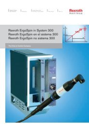
<strong>Rexroth</strong> <strong>Tightening</strong> <strong>System</strong> <strong>300</strong><br />
<strong>Rexroth</strong> <strong>Sistema</strong> <strong>de</strong> <strong>atornillado</strong> <strong>300</strong><br />
<strong>Rexroth</strong> <strong>Sistema</strong> <strong>de</strong> parafusamento <strong>300</strong><br />
M (T)<br />
M1 (T1)<br />
1<br />
The Drive & Control Company
2<br />
Bosch <strong>Rexroth</strong> AG<br />
<strong>Tightening</strong> <strong>System</strong> <strong>300</strong><br />
6 Bosch <strong>Rexroth</strong> AG<br />
Stationary multiple spindle system in the engine assembly<br />
Atornilladora múltiple estacionaria para el montaje <strong>de</strong> motores<br />
Parafusa<strong>de</strong>ira estacionária múltipla para montagem <strong>de</strong> motores<br />
Explanation of symbols in the cover<br />
Explicación <strong>de</strong> los símbolos en la cubierta<br />
Explicação dos símbolos na dobra da capa
<strong>Tightening</strong> <strong>System</strong> <strong>300</strong><br />
Bosch <strong>Rexroth</strong> AG 3<br />
Symbols<br />
Símbolos<br />
Símbolos<br />
d min<br />
●<br />
●<br />
●<br />
●<br />
●<br />
●<br />
●<br />
●<br />
●<br />
Minimum center to center [min]<br />
Number of spindles<br />
Diámetro <strong>de</strong>l círculo primitivo mínimo [min]<br />
Número <strong>de</strong> husillos<br />
Menor diâmetro <strong>de</strong> círculo primitivo <strong>de</strong><br />
referência [min]<br />
Quantida<strong>de</strong> <strong>de</strong> fusos<br />
3-1<br />
Reference to a specific page<br />
Referencia a una página <strong>de</strong>terminada<br />
Indicação <strong>de</strong> página<br />
Torque range [Nm]<br />
Intervalo <strong>de</strong>l par <strong>de</strong> apriete [Nm]<br />
Faixa <strong>de</strong> torque [Nm]<br />
Output drive speed [1/min]<br />
Número <strong>de</strong> revoluciones <strong>de</strong> salida [1/min]<br />
Rotação do cabeçote [1/min]<br />
Co<strong>de</strong><br />
Part co<strong>de</strong><br />
Código <strong>de</strong> la pieza<br />
Códigos <strong>de</strong> peças<br />
EC motor<br />
Motor EC<br />
Motor EC<br />
Planetary gearbox<br />
Engranaje planetario<br />
Redutor planetária<br />
Measurement transducer<br />
Sensor <strong>de</strong> medición<br />
Sensor <strong>de</strong> medição<br />
Adapter:<br />
... AVR redundancy adapter for fitting a<br />
measurement transducer and an offset<br />
output drive with integrated transducer<br />
... AVG adapter between planetary gearbox<br />
and offset output drive with integrated<br />
transducer<br />
... AR redundancy adapter for fitting two<br />
measurement transducers<br />
... AX axial compensator, e.g. on angle head<br />
... Ay adapter between BGy gearbox and<br />
BGx measurement transducer (replacement<br />
transducer)<br />
... A adapter between BGx gearbox and<br />
BGx output drive<br />
Adaptador:<br />
... Adaptador <strong>de</strong> redundancia AVR para el<br />
montaje <strong>de</strong> un sensor <strong>de</strong> medición y un cabezal<br />
<strong>de</strong> salida supletorio con sensor integrado<br />
... Adaptador AVG entre el engranaje planetario<br />
y el cabezal <strong>de</strong> salida supletorio<br />
con sensor integrado<br />
... Adaptador <strong>de</strong> redundancia AR para la<br />
instalación <strong>de</strong> dos sensores <strong>de</strong> medición<br />
... Compensación axial AX, p. ej. en el<br />
cabezal acodado<br />
... Adaptador Ay entre el engranaje BGy y el<br />
sensor <strong>de</strong> medición BGx (reemplazo <strong>de</strong> sensor)<br />
... Adaptador A entre el engranaje BGx y el<br />
cabezal <strong>de</strong> salida BGx<br />
Adaptador:<br />
... Adaptador <strong>de</strong> redundância AVR para<br />
montagem <strong>de</strong> um sensor <strong>de</strong> medição e <strong>de</strong><br />
um cabeçote <strong>de</strong> saída <strong>de</strong>slocado com sensor<br />
integrado<br />
... Adaptador AVG entre redutor planetário<br />
e cabeçote <strong>de</strong> saída <strong>de</strong>slocado com sensor<br />
integrado<br />
... AR adaptador <strong>de</strong> redundância para<br />
instalação <strong>de</strong> dois sensores <strong>de</strong> medição<br />
... AX compensação axial no cabeçote angular<br />
... Ay adaptador entre redutor BGy e sensor<br />
BGx (substituição <strong>de</strong> sensores)<br />
... A adaptador entre redutor BGx e<br />
cabeçote <strong>de</strong> saída BGx<br />
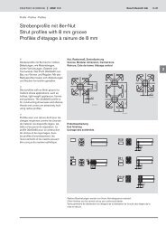
b<br />
a<br />
Transverse gearbox (a [mm] = installation<br />
length input drive si<strong>de</strong>, b [mm] =<br />
installation length output drive si<strong>de</strong>)<br />
Engranaje <strong>de</strong> inversión (a [mm] = longitud<br />
<strong>de</strong> instalación por el lado <strong>de</strong> accionamiento,<br />
b[mm]= longitud <strong>de</strong> instalación por el lado<br />
<strong>de</strong> salida).<br />
Transmissão transversal (a [mm] = comprimento<br />
<strong>de</strong> montagem no lado do<br />
acionamento, b [mm] = comprimento <strong>de</strong><br />
montagem no lado do cabeçote)<br />
Straight output drive<br />
Soporte <strong>de</strong>l husillo<br />
Cabeçote reto<br />
Offset output drive with integrated<br />
transducer<br />
Cabezal <strong>de</strong> salida supletorio con<br />
sensor integrado<br />
Cabeçote <strong>de</strong> saída <strong>de</strong>slocado com sensor<br />
integrado<br />
Angle head with integrated transducer<br />
Cabezal acodado con sensor integrado<br />
Cabeçote angular com sensor integrado<br />
Offset output drive<br />
Cabezal <strong>de</strong> salida supletorio<br />
Cabeçote <strong>de</strong> saída <strong>de</strong>slocado<br />
Angle head<br />
Cabezal acodado<br />
Cabeçote angular<br />
Feed output drive<br />
Cabezal <strong>de</strong> avance<br />
Cabeçote com avanço
4 Bosch <strong>Rexroth</strong> AG<br />
<strong>Tightening</strong> <strong>System</strong> <strong>300</strong><br />
Hand-held 8-fold nutrunner for the assembly of connecting rods<br />
Atornillador manual <strong>de</strong> 8 elementos para el montaje <strong>de</strong> bielas<br />
Parafusa<strong>de</strong>ira manual <strong>de</strong> 8 elementos para a montagem <strong>de</strong> bielas
<strong>Tightening</strong> <strong>System</strong> <strong>300</strong><br />
Bosch <strong>Rexroth</strong> AG 5<br />
Contents<br />
Índice<br />
Índice<br />
Page<br />
Introduction<br />
<strong>Tightening</strong> system <strong>300</strong> 6<br />
<strong>Tightening</strong> spindles 0.6-1000 Nm 8<br />
The way to the correct tightening<br />
spindle 10<br />
<strong>Tightening</strong> spindles sizes 2-5<br />
EC tightening spindles size 2 12<br />
EC tightening spindles size 3 14<br />
EC tightening spindles size 4 16<br />
EC tightening spindles size 5 18<br />
Control components<br />
Card racks and system boxes 20<br />
<strong>System</strong> box SB301 21<br />
<strong>System</strong> box SB305 22<br />
Card racks BT<strong>300</strong> 23<br />
Power supply module VM<strong>300</strong> 24<br />
<strong>Tightening</strong> controller SE3xx 25<br />
Servo amplifier LT303/304/305 26<br />
Communication unit KE310 27<br />
Communication unit KE312 28<br />
Interface modules 29<br />
Planning assistance:<br />
Interface module 35<br />
Single-channel operation 36<br />
Multi-channel operation of up to<br />
40 channels 38<br />
<strong>System</strong> components and 40<br />
non-standard accessories<br />
Planning assistance for BT<strong>300</strong><br />
equipment 42<br />
Cable sets<br />
Cable selection 43<br />
Measurement transducer cable 45<br />
Operation<br />
<strong>System</strong> display SD301 46<br />
Operating system BS<strong>300</strong> 48<br />
Technical appendix 50<br />
Introduction of<br />
Bosch <strong>Rexroth</strong> catalogs 56<br />
Sales organization 57<br />
Symbols on a fold-out in the cover<br />
Página<br />
Introducción<br />
<strong>Sistema</strong> <strong>de</strong> <strong>atornillado</strong> <strong>300</strong> 6<br />
Husillos <strong>atornillado</strong>res 0,6-1000 Nm 8<br />
El camino hasta el husillo <strong>atornillado</strong>r<br />
correcto 10<br />
Husillos <strong>atornillado</strong>res <strong>de</strong><br />
tamaños 2-5<br />
Husillos <strong>atornillado</strong>res EC, tamaño 2 12<br />
Husillos <strong>atornillado</strong>res EC, tamaño 3 14<br />
Husillos <strong>atornillado</strong>res EC, tamaño 4 16<br />
Husillos <strong>atornillado</strong>res EC, tamaño 5 18<br />
Componentes <strong>de</strong> control<br />
Portamódulos y cajas <strong>de</strong> sistema 20<br />
Caja <strong>de</strong> sistema SB301 21<br />
Caja <strong>de</strong> sistema SB305 22<br />
Portamódulos BT<strong>300</strong> 23<br />
Módulo <strong>de</strong> alimentación VM<strong>300</strong> 24<br />
Control <strong>de</strong> <strong>atornillado</strong> SE311 y SE312 25<br />
Módulos <strong>de</strong> potencia LT303/304/305 26<br />
Unidad <strong>de</strong> comunicación KE310 27<br />
Unidad <strong>de</strong> comunicación KE312 28<br />
Módulo <strong>de</strong> interface 29<br />
Ayuda para planificación:<br />
Módulo <strong>de</strong> interface 35<br />
Operación monocanal 36<br />
Operación multicanal<br />
hasta 40 canales 38<br />
Componentes <strong>de</strong> sistema y accesorios<br />
especiales 40<br />
Ayuda para planificación <strong>de</strong>l<br />
equipamiento BT<strong>300</strong> 42<br />
Juegos <strong>de</strong> cables (<strong>de</strong> conexión)<br />
Selección <strong>de</strong> cables 43<br />
Cable <strong>de</strong>l sensor <strong>de</strong> medición 45<br />
Manejo<br />
Pantalla <strong>de</strong>l sistema SD301 46<br />
<strong>Sistema</strong> <strong>de</strong> manejo BS<strong>300</strong> 48<br />
Anexo técnico 50<br />
Presentación <strong>de</strong> los catálogos<br />
Bosch <strong>Rexroth</strong> 56<br />
Red <strong>de</strong> distribución 57<br />
Hoja <strong>de</strong>splegable <strong>de</strong> símbolos en<br />
la cubierta<br />
Página<br />
Introdução<br />
<strong>Sistema</strong> <strong>de</strong> parafusamento <strong>300</strong> 6<br />
Parafusa<strong>de</strong>iras 0,6-1000 Nm 8<br />
A escolha da parafusa<strong>de</strong>ira certa 10<br />
Parafusa<strong>de</strong>iras Tamanhos 2-5<br />
Parafusa<strong>de</strong>iras EC, tamanho 2 12<br />
Parafusa<strong>de</strong>iras EC, tamanho 3 14<br />
Parafusa<strong>de</strong>iras EC, tamanho 4 16<br />
Parafusa<strong>de</strong>iras EC, tamanho 5 18<br />
Componentes <strong>de</strong> comando<br />
Porta-módulos e caixas <strong>de</strong> sistema 20<br />
Caixa <strong>de</strong> sistema SB301 21<br />
Caixa <strong>de</strong> sistema SB305 22<br />
Porta-módulos BT<strong>300</strong> 23<br />
Módulo <strong>de</strong> alimentação VM<strong>300</strong> 24<br />
Comando <strong>de</strong> parafusa<strong>de</strong>ira<br />
SE311 e SE312 25<br />
Unida<strong>de</strong>s <strong>de</strong> potência<br />
LT303/304/305 26<br />
Unida<strong>de</strong> <strong>de</strong> comunicação KE310 27<br />
Unida<strong>de</strong> <strong>de</strong> comunicação KE312 28<br />
Módulo <strong>de</strong> interface 29<br />
Apoio para planejamento:<br />
Módulo <strong>de</strong> interface 35<br />
Funcionamento monocanal 36<br />
Funcionamento multicanal até<br />
40 canais 38<br />
Componentes <strong>de</strong> sistema e acessórios<br />
especiais 40<br />
Apoio <strong>de</strong> planejamento da<br />
equipagem BT<strong>300</strong> 42<br />
Conjuntos <strong>de</strong> cabos<br />
Seleção dos cabos 43<br />
Cabo do sensor <strong>de</strong> medição 45<br />
Operação<br />
Display SD301 46<br />
<strong>Sistema</strong> <strong>de</strong> operação BS<strong>300</strong> 48<br />
A<strong>de</strong>ndo técnico 50<br />
Apresentação dos catálogos<br />
Bosch <strong>Rexroth</strong> 56<br />
Organização <strong>de</strong> vendas 57<br />
Símbolos na dobra da capa
6<br />
Bosch <strong>Rexroth</strong> AG<br />
<strong>Tightening</strong> <strong>System</strong> <strong>300</strong><br />
<strong>Tightening</strong> <strong>System</strong> <strong>300</strong><br />
<strong>Sistema</strong> <strong>de</strong> <strong>atornillado</strong> <strong>300</strong><br />
<strong>Sistema</strong> <strong>de</strong> parafusamento <strong>300</strong><br />
■ A fast market <strong>de</strong>mands flexible<br />
production systems<br />
The <strong>Rexroth</strong> <strong>Tightening</strong> <strong>System</strong> <strong>300</strong> has<br />
been <strong>de</strong>veloped for a market that is fast<br />
living and flexible. Shorter product<br />
cycles and changing tasks require a<br />
variable technology with simple handling.<br />
Controller and tightening spindle have<br />
been <strong>de</strong>veloped as a modular system,<br />
which ensures an optimal construction<br />
using standard components. Further<br />
extensions are simplicity itself. This<br />
system, which can be exten<strong>de</strong>d up to<br />
40 tightening channels, is coordinated<br />
by a communication unit (KE). The<br />
interface-oriented PC software BS<strong>300</strong><br />
makes programming clear and easy.<br />
Servo amplifier (LT), controller (SE)<br />
and communication unit (KE) form a<br />
powerful unit in the system card rack<br />
(BT) with compact sli<strong>de</strong>-in modules.<br />
As alternatives to the system card rack<br />
(BT), the SB301 system box is available<br />
for the inclusion of a single tightening<br />
channel and the SB305 system box for<br />
the inclusion of up to five tightening<br />
channels. All cards can be quickly<br />
plugged in. This modularity ensures<br />
easy system installation.<br />
A single connector cable suffices to<br />
connect the tightening controller with<br />
the servo amplifier. This cable provi<strong>de</strong>s<br />
both power supply and communications.<br />
In the process, distances of up to 100<br />
meters can be safely bridged.<br />
■ Un mercado rápido exige sistemas<br />
<strong>de</strong> producción flexibles<br />
El sistema <strong>de</strong> <strong>atornillado</strong> <strong>300</strong> <strong>de</strong><br />
<strong>Rexroth</strong> ha sido i<strong>de</strong>ado para un mercado<br />
flexible y en continuo <strong>de</strong>sarrollo.<br />
Los ciclos <strong>de</strong> producción más cortos y<br />
la diversificación <strong>de</strong> tareas requieren<br />
una técnica variada <strong>de</strong> sencillo manejo.<br />
La unidad <strong>de</strong> control y los husillos <strong>atornillado</strong>res<br />
se han <strong>de</strong>sarrollado según<br />
principio <strong>de</strong> sistema modular. Ésto garantiza<br />
una configuración óptima con<br />
componentes estándar. Las ampliaciones<br />
posteriores son sencillas <strong>de</strong> realizar.<br />
El sistema, al cual se pue<strong>de</strong>n acoplar<br />
hasta 40 canales <strong>de</strong> <strong>atornillado</strong>, se<br />
coordina por una unidad <strong>de</strong> comunicación<br />
(KE). El software BS<strong>300</strong> para PC,<br />
guiado por la superficie <strong>de</strong> la pantalla,<br />
hace que la programación sea clara y<br />
sencilla. El módulo <strong>de</strong> potencia (LT), la<br />
unidad <strong>de</strong> control (SE) y la unidad <strong>de</strong><br />
comunicación (KE) constituyen en el<br />
portamódulos <strong>de</strong> sistema (BT), con<br />
módulos compactos y conectables, una<br />
unidad <strong>de</strong> gran rendimiento. Como<br />
alternativa para el portamódulos <strong>de</strong><br />
sistema (BT), se dispone <strong>de</strong> la caja <strong>de</strong><br />
sistema SB301 para el alojamiento <strong>de</strong><br />
un canal <strong>de</strong> <strong>atornillado</strong> y la caja <strong>de</strong><br />
sistema SB305 para el alojamiento <strong>de</strong><br />
hasta cinco canales <strong>de</strong> <strong>atornillado</strong>.<br />
Todos los módulos se introducen rápidamente.<br />
Spindle connector cable up to 100 m in length<br />
Cable <strong>de</strong> conexión <strong>de</strong>l husillo <strong>de</strong> hasta 100 m <strong>de</strong><br />
longitud<br />
Cabo <strong>de</strong> ligação para parafusa<strong>de</strong>ira com até<br />
100 m <strong>de</strong> comprimento<br />
Esta modularidad le garantiza una instalación<br />
<strong>de</strong>l sistema sencilla.<br />
Para conectar la unidad <strong>de</strong> control<br />
y el módulo <strong>de</strong> potencia basta un solo<br />
cable <strong>de</strong> conexión. Dicho cable se<br />
encarga <strong>de</strong>l suministro <strong>de</strong> energía y <strong>de</strong><br />
la comunicación. Mediante el mismo, se<br />
pue<strong>de</strong>n salvar con seguridad distancias<br />
<strong>de</strong> hasta 100 metros.
<strong>Tightening</strong> <strong>System</strong> <strong>300</strong><br />
Bosch <strong>Rexroth</strong> AG 7<br />
The interface-oriented PC software BS<strong>300</strong> makes<br />
system programming easy.<br />
El software BS<strong>300</strong> para PC guiado por la<br />
superficie <strong>de</strong> la pantalla facilita la programación<br />
<strong>de</strong>l sistema.<br />
Um software <strong>de</strong> PC orientado para superfícies BS<strong>300</strong><br />
torna a programação do sistema muito simples.<br />
The system can be exten<strong>de</strong>d up to 40 tightening<br />
channels.<br />
El sistema pue<strong>de</strong> ser ampliado por hasta 40 canales<br />
<strong>de</strong> <strong>atornillado</strong>.<br />
O sistema é ampliável para até 40 canais <strong>de</strong> parafusamento<br />
■ Um mercado rápido exige<br />
sistemas <strong>de</strong> produção flexíveis.<br />
O sistema <strong>de</strong> parafusamento <strong>300</strong> da<br />
<strong>Rexroth</strong> foi <strong>de</strong>senvolvido para um mercado<br />
dinâmico e flexível. Ciclos <strong>de</strong><br />
produtos mais breves e tarefas alternantes<br />
exigem uma tecnologia variável,<br />
<strong>de</strong> manuseio simples.<br />
O comando e a parafusa<strong>de</strong>ira foram<br />
<strong>de</strong>senvolvidos pelo princípio modular.<br />
Isto garante uma equipagem i<strong>de</strong>al<br />
com componentes padrões, o que<br />
facilita a realização <strong>de</strong> extensões<br />
posteriores. O sistema, que po<strong>de</strong> ser<br />
ampliado para até 40 canais <strong>de</strong> parafusamento,<br />
é coor<strong>de</strong>nado por uma<br />
unida<strong>de</strong> <strong>de</strong> comunicação (KE). O<br />
software BS<strong>300</strong>, orientado para o<br />
ambiente gráfico <strong>de</strong> PC torna a pro<br />
gramação fácil e visualizável.<br />
As unida<strong>de</strong>s <strong>de</strong> potência (LT), o<br />
comando (SE) e a unida<strong>de</strong> <strong>de</strong> comunicação<br />
(KE) formam uma unida<strong>de</strong> <strong>de</strong><br />
alto <strong>de</strong>sempenho no suporte <strong>de</strong> componentes<br />
<strong>de</strong> sistema (BT), junto com<br />
circuitos encaixáveis e compactos.<br />
Como alternativas para o porta-módulos<br />
(BT) estão disponíveis a caixa <strong>de</strong><br />
sistema SB301, para receber um canal<br />
<strong>de</strong> parafusamento, e a caixa <strong>de</strong> sistema<br />
305, para receber até cinco canais<br />
<strong>de</strong> parafusamento. Todos os módulos<br />
encaixamse rapidamente e esta<br />
modularida<strong>de</strong> garante uma instalação<br />
simples do sistema.<br />
Para conectar o comando e a unida<strong>de</strong><br />
<strong>de</strong> potência, basta um único cabo <strong>de</strong><br />
ligação. Este cabo aten<strong>de</strong> a alimentação<br />
<strong>de</strong> energia e a comunicação, permitindo<br />
interligar distâncias <strong>de</strong> até<br />
100 metros com segurança.
8<br />
Bosch <strong>Rexroth</strong> AG<br />
<strong>Tightening</strong> <strong>System</strong> <strong>300</strong><br />
<strong>Tightening</strong> spindles 0.6-1000 Nm<br />
Husillos <strong>atornillado</strong>res 0,6-1000 Nm<br />
Parafusa<strong>de</strong>iras 0,6-1000 Nm<br />
■ <strong>Tightening</strong> spindle<br />
– Modular construction<br />
– IP 54<br />
– Secure digital data transmission for<br />
up to 100 m of cable<br />
■ Motor<br />
– Simple installation<br />
– Reliable EC motor<br />
– Short tightening times<br />
– High dynamics<br />
– Maintenance-free<br />
– Minimum external dimensions make<br />
it easy to integrate<br />
■ Transverse gearbox<br />
– Reduction of the installation length<br />
■ Planetary gearbox<br />
– Simple installation<br />
– Several gearboxes per product series<br />
■ Husillo <strong>atornillado</strong>r<br />
– Construcción modular<br />
– IP 54<br />
– Transmisión digital segura <strong>de</strong> datos<br />
para cables <strong>de</strong> hasta 100 m <strong>de</strong><br />
longitud<br />
■ Motor<br />
– Instalación simple<br />
– Motor EC fiable<br />
– Tiempos cortos <strong>de</strong> <strong>atornillado</strong><br />
– Dinámica elevada<br />
– Exento <strong>de</strong> mantenimiento<br />
– Dimensiones exteriores reducidas, <strong>de</strong><br />
ahí su buena correspon<strong>de</strong>ncia<br />
■ Engranaje <strong>de</strong> inversión<br />
– Reducción <strong>de</strong> la longitud <strong>de</strong><br />
instalación<br />
■ Engranaje planetario<br />
– Instalación simple<br />
– Varios engranajes por serie<br />
■ Parafusa<strong>de</strong>ira<br />
– Configuração modular<br />
– IP 54<br />
– Transmissão digital segura <strong>de</strong> dados<br />
em cabos <strong>de</strong> até 100 m <strong>de</strong><br />
comprimento<br />
■ Motor<br />
– Instalação simples<br />
– Motor EC confiável<br />
– Tempos curtos <strong>de</strong><br />
parafusamento<br />
– Dinâmica gran<strong>de</strong><br />
– Isento <strong>de</strong> manutenção<br />
– Medidas externas reduzidas<br />
com consequente intercambiabilida<strong>de</strong><br />
■ Transmissão transversal<br />
– Redução do comprimento <strong>de</strong><br />
montagem<br />
■ Redutor planetária<br />
– Instalação simples<br />
– Vários redutores por série
<strong>Tightening</strong> <strong>System</strong> <strong>300</strong><br />
Bosch <strong>Rexroth</strong> AG 9<br />
■ Measurement transducer<br />
– Simple installation<br />
– Action transducer, contactless,<br />
maintenance-free<br />
– Direct evaluation of torque,<br />
angle of turn and gradient<br />
– Integrated cycle counter<br />
– Can be used as a redundancy<br />
transducer for exten<strong>de</strong>d system<br />
assurance<br />
■ Sensor <strong>de</strong> medición<br />
– Instalación simple<br />
– Sensor <strong>de</strong> acción sin contacto<br />
exento <strong>de</strong> mantenimiento<br />
– Evaluación directa <strong>de</strong>l par <strong>de</strong> apriete,<br />
<strong>de</strong>l ángulo <strong>de</strong> giro y <strong>de</strong>l gradiente<br />
– Contador <strong>de</strong> ciclos integrado<br />
– Utilizable como sensor redundante<br />
para un mayor aseguramiento <strong>de</strong>l<br />
sistema<br />
■ Sensores <strong>de</strong> medição<br />
– Instalação simples<br />
– Sensor <strong>de</strong> ativação sem<br />
contatos, sem manutenção<br />
– Avaliação direta do torque, ângulo e<br />
gradiente<br />
– Contador <strong>de</strong> ciclos integrado<br />
– Utilizável como sensor <strong>de</strong><br />
redundância para segurança<br />
adicional do sistema<br />
■ Output drives<br />
– Simple installation<br />
– The appropriate output drive for<br />
every use<br />
■ Cabezales <strong>de</strong> salida<br />
– Instalación simple<br />
– Para cada aplicación hay un cabezal<br />
<strong>de</strong> salida a<strong>de</strong>cuado<br />
■ Cabeçotes <strong>de</strong> saída<br />
– Instalação simple<br />
– Para cada aplicação o cabeçote<br />
certo<br />
■ VMC/WMC<br />
– Torque measuring directly at the screw<br />
– Measurement transfer without slip ring<br />
– Compact construction<br />
– Measurements not influenced by<br />
fluctuation in efficiency<br />
■ VMC/WMC<br />
– Medición <strong>de</strong>l par <strong>de</strong> giro directamente<br />
en el tornillo<br />
– Transmisión <strong>de</strong> los valores <strong>de</strong><br />
medición sin anillo <strong>de</strong> <strong>de</strong>sgaste<br />
– Mo<strong>de</strong>lo compacto<br />
– Sin influenciar los valores <strong>de</strong> medición<br />
por variaciones <strong>de</strong>l<br />
rendimiento<br />
■ VMC/WMC<br />
– Medição do torque diretamente no<br />
parafuso<br />
– Transmissão dos valores medidos<br />
sem anel coletor<br />
– Construção compacta<br />
– Sem influenciar os valores medidos<br />
por flutuação do grau <strong>de</strong> rendimento
10<br />
Bosch <strong>Rexroth</strong> AG<br />
<strong>Tightening</strong> <strong>System</strong> <strong>300</strong><br />
The way to the correct tightening spindle<br />
El camino hasta el husillo <strong>atornillado</strong>r correcto<br />
A escolha da parafusa<strong>de</strong>ira certa<br />
■ The modular construction of the<br />
<strong>Rexroth</strong> tightening spindles enables a<br />
very precise adjustment of the tightening<br />
spindle to the tightening task at<br />
hand, as well as the necessary precision<br />
and safety requirements. The selection<br />
of tightening spindle components<br />
ensues from parameters 1–6. <strong>Tightening</strong><br />
spindles should be selected in such a<br />
way that they are loa<strong>de</strong>d up to 80%.<br />
■ La construcción modular <strong>de</strong> los husillos<br />
<strong>atornillado</strong>res <strong>de</strong> <strong>Rexroth</strong> posibilita una<br />
adaptación muy precisa <strong>de</strong>l husillo a su<br />
tarea <strong>de</strong> <strong>atornillado</strong>, a sus exigencias <strong>de</strong><br />
precisión y <strong>de</strong> seguridad. Para la elección<br />
<strong>de</strong> los componentes <strong>de</strong>l husillo <strong>atornillado</strong>r,<br />
hay que tener en cuenta los parámetros<br />
<strong>de</strong> 1 a 6. La elección <strong>de</strong> los husillos<br />
<strong>atornillado</strong>res <strong>de</strong>be ser tal, que la carga<br />
que éstos reciban sea <strong>de</strong> hasta el 80 %.<br />
■ A configuração modular das parafusa<strong>de</strong>iras<br />
<strong>Rexroth</strong> possibilita um ajuste<br />
muito preciso da parafusa<strong>de</strong>ira ao trabalho<br />
<strong>de</strong> parafusamento, aos requisitos<br />
<strong>de</strong> precisão e segurança. A escolha<br />
dos componentes <strong>de</strong> parafusa<strong>de</strong>ira<br />
resulta dos parâmetros 1-6. As parafusa<strong>de</strong>iras<br />
<strong>de</strong>veriam ser selecionadas<br />
<strong>de</strong> modo que sejam submetidas a até<br />
80 % da capacida<strong>de</strong> <strong>de</strong> carga.<br />
M (T)<br />
M1 (T1)<br />
1<br />
Torque<br />
Par <strong>de</strong> apriete<br />
Torque<br />
2<br />
BG 2 0,6 – 12 Nm<br />
BG 3 3,5 – 55 Nm<br />
BG 4 12 – 340 Nm<br />
BG 5 48 – 1000 Nm<br />
Sizes (BG)<br />
Tamaños (BG)<br />
Tamanhos (BG)<br />
3<br />
d min<br />
Center to center distance<br />
Distancia entre tornillos<br />
Distância entre parafuso<br />
4<br />
Tool mount<br />
Alojamiento <strong>de</strong> herramientas<br />
Alojamento <strong>de</strong> ferramenta
<strong>Tightening</strong> <strong>System</strong> <strong>300</strong><br />
Bosch <strong>Rexroth</strong> AG 11<br />
2<br />
5<br />
1<br />
6<br />
4<br />
3<br />
Explanation of symbols – on a fold-out in the<br />
cover at the back<br />
Explicación <strong>de</strong>splegable <strong>de</strong> los símbolos en la<br />
cubierta posterior<br />
Explicação dos símbolos na dobra da capa<br />
traseira<br />
nAbtr. min [min -1 ] = 60 · xG<br />
ts [s]<br />
nAbtr. min = min. output drive speed<br />
xG = screw-in thread turns G<br />
ts = pure tightening time<br />
5 6<br />
M [Nm]<br />
25<br />
20<br />
15<br />
10<br />
5<br />
0<br />
2GE19<br />
2GE26<br />
2GE19<br />
2GE26<br />
200 400 600 800 1000<br />
n [1/min]<br />
M<br />
1<br />
M [Nm]<br />
10<br />
8<br />
EC302/2GE26<br />
6<br />
4<br />
2<br />
0 1 2 3 4 5 6<br />
t [s]<br />
s<br />
nAbtr. min [min -1 ] = 60 · xG<br />
ts [s]<br />
nAbtr. min = n° <strong>de</strong> revoluciones mínimo <strong>de</strong>l cabezal<br />
<strong>de</strong> salida<br />
xG = pasos <strong>de</strong> rosca a atornillar G<br />
ts = tiempo efectivo <strong>de</strong> <strong>atornillado</strong><br />
Motor characteristics<br />
Curva característica <strong>de</strong>l motor<br />
Diagrama do motor<br />
Cycle time graph<br />
Curva <strong>de</strong> secuencia <strong>de</strong> ciclos <strong>de</strong> trabajo<br />
Curva <strong>de</strong> cadência<br />
nAbtr. min [min -1 ] = 60 · xG<br />
ts [s]<br />
nAbtr. min = rotação mínima do cabeçote <strong>de</strong> saída<br />
xG = passos <strong>de</strong> rosca a serem girados G<br />
ts = puro tempo <strong>de</strong> parafusamento<br />
Note on: <strong>de</strong>pen<strong>de</strong>ncies ( fold-out page at the back)<br />
Indicación para: <strong>de</strong>pen<strong>de</strong>ncias ( cubierta posterior)<br />
Notas referentes a: inter<strong>de</strong>pendências ( dobra da capa traseira)
12 Bosch <strong>Rexroth</strong> AG<br />
<strong>Tightening</strong> <strong>System</strong> <strong>300</strong><br />
EC tightening spindles size 2<br />
Husillos <strong>atornillado</strong>res EC, tamaño 2<br />
Parafusa<strong>de</strong>iras EC, tamanho 2<br />
BG 2<br />
0,6–12 Nm<br />
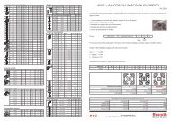
EC302 2GE19 2MC.. 2G.. 2S.. 2VN.. 2W..<br />
2GE26<br />
<strong>Tightening</strong> spindle<br />
work area<br />
Área <strong>de</strong> trabajo <strong>de</strong> los<br />
husillos <strong>atornillado</strong>res<br />
Faixa <strong>de</strong> trabalho das<br />
parafusa<strong>de</strong>iras<br />
[Nm] Co<strong>de</strong> [1/min] [1/min] Co<strong>de</strong> Co<strong>de</strong><br />
2GE19 2GE26<br />
0,6–2,5 1000 780 2G...<br />
0,6–2,5 1000 780<br />
2MC003<br />
2VN...<br />
0,6–2,5 1000 820 2W11<br />
0,6–2,5 1000 780 2S...<br />
1,5–5,5 1000 780 2G...<br />
1,5–5 1000 780 2VN...<br />
1,5–5,5 EC302 1000 820 2MC006<br />
2W11<br />
1,5–5 1000 780 2S...<br />
2,5–10 1000 780 2G...<br />
2,5–10 1000 780 2VN...<br />
2,5–11 1000 820 2MC012<br />
2W11<br />
2,5–10 1000 780 2S1<br />
2,5–7 1000 780 2S2<br />
d min = mm<br />
M [Nm]<br />
25<br />
20<br />
15<br />
10<br />
5<br />
0<br />
2GE19<br />
2GE26<br />
2GE19<br />
2GE26<br />
200 400 600 800 1000<br />
n [1/min]<br />
M [Nm]<br />
10<br />
8<br />
EC302/2GE26<br />
6<br />
4<br />
2<br />
0 1 2 3 4 5 6<br />
t [s]<br />
s<br />
d min<br />
●<br />
●<br />
●<br />
●<br />
●<br />
●<br />
●<br />
●<br />
●<br />
●<br />
●<br />
●<br />
●<br />
●<br />
●<br />
●<br />
●<br />
●<br />
●<br />
●<br />
34 46 63 64 70<br />
23 27 33 41 52<br />
33 38 46 55 65<br />
26 30 36 44 52<br />
Motor characteristics<br />
Curva característica <strong>de</strong>l motor<br />
Diagrama do motor<br />
Max. torque/cycle time<br />
Par <strong>de</strong> apriete máx./secuencia <strong>de</strong> ciclos <strong>de</strong> trabajo<br />
Torque max./cadência<br />
Multiple spindle combinations<br />
Correspon<strong>de</strong>ncia <strong>de</strong> los husillos <strong>atornillado</strong>res<br />
Intercambiabilida<strong>de</strong> das parafusa<strong>de</strong>iras<br />
Note on: <strong>de</strong>pen<strong>de</strong>ncies ( fold-out page at the back)<br />
Indicación para: <strong>de</strong>pen<strong>de</strong>ncias ( cubierta posterior)<br />
Notas referentes a: inter<strong>de</strong>pendências ( dobra da capa traseira)
<strong>Tightening</strong> <strong>System</strong> <strong>300</strong><br />
Bosch <strong>Rexroth</strong> AG 13<br />
EC..<br />
Co<strong>de</strong> No [Nm] Mmax[Nm] i = η = a [mm] b [mm] [mm] [kg]<br />
2ULG<br />
b<br />
a<br />
EC302 0 608 701 016 – – – – – – 211 0,72<br />
2ULG 0 608 PE0 282 – – 1 0,9 66,1 28,3 – 0,4<br />
2GE..<br />
2GE19 0 608 720 043 – 12 18,9 0,90 – – 50,9 0,4<br />
2GE26 0 608 720 038 – 12 25,5 0,90 – – 50,9 0,4<br />
2MC.. 2MC003 0 608 820 095 3 – 1,0 0,99 – – 118,5 0,55<br />
2MC006 0 608 820 096 6 – 1,0 0,99 – – 118,5 0,55<br />
2MC012 0 608 820 097 12 – 1,0 0,99 – – 118,5 0,55<br />
Co<strong>de</strong> No Mmax[Nm] i = η = [mm] ’A’ [mm] [mm] [kg]<br />
2AR.. 2AR 0 608 810 020 – 1,0 0,99 – – – 50,0 0,3<br />
2AX 3 607 030 018 – 1,0 0,99 20 1/4" – 106,0 0,2<br />
2A3 3 600 760 064 – 1,0 0,99 – – – 11,5 0,4<br />
2A 0 608 810 024 – 1,0 0,99 – – – 30,0 0,4<br />
2GA..<br />
2GA82 0 608 800 077 10 1,0 0,99 20 1/4" 8 ’A’ +8 0,2<br />
2GB82 0 608 800 078 10 1,0 0,99 20 1/4" 8 ’A’ +8 0,2<br />
2VNA..<br />
2VNA82 0 608 800 607 10 1,0 0,90 20 1/4" 82 ’A’ +71 0,6<br />
2VNB82 0 608 800 608 10 1,0 0,90 20 1/4" 82 ’A’ +71 0,6<br />
2W..<br />
2S..<br />
2W11 0 608 810 041 11 1,05 0,95 – 1/4" – 81,5 0,7<br />
2S1 0 608 800 612 10 1,0 0,93 – 1/4" 80 ’A’ +89,5 2,0<br />
2S2 0 608 800 619 7 1,0 0,93 – M 6 1) 80 ’A’ +89,5 2,0<br />
** Note on: max. air pressure p (55) [mm] 160<br />
** Indicación para: presión máx. <strong>de</strong> aire ( 55) [mm] 160<br />
** Observação: pressão máx. do ar ( 55) [mm] 160<br />
1)<br />
External thread<br />
1)<br />
Rosca exterior<br />
1)<br />
Rosca externa<br />
Explanation of symbols ( 3 + 58)<br />
Explicación <strong>de</strong> los símbolos ( 3 + 58)<br />
Explicação dos símbolos ( 3 + 58)
14 Bosch <strong>Rexroth</strong> AG<br />
<strong>Tightening</strong> <strong>System</strong> <strong>300</strong><br />
EC tightening spindles size 3<br />
Husillos <strong>atornillado</strong>res EC, tamaño 3<br />
Parafusa<strong>de</strong>iras EC, tamanho 3<br />
3A<br />
WMC<br />
VMC<br />
3AR<br />
BG 3<br />
3,5–55 Nm<br />
VMC<br />
WMC<br />
EC303<br />
3GE27<br />
3GE67<br />
3MC.. G.. 3S.. VN.. 3W..<br />
<strong>Tightening</strong> spindle<br />
work area<br />
Área <strong>de</strong> trabajo <strong>de</strong> los<br />
husillos <strong>atornillado</strong>res<br />
Faixa <strong>de</strong> trabalho das<br />
parafusa<strong>de</strong>iras<br />
[Nm] Co<strong>de</strong> [1/min] [1/min] Co<strong>de</strong> Co<strong>de</strong><br />
3GE27 3GE67<br />
3,5–16 740 295 G1... / G2...<br />
3,5–14,5 740 295<br />
3MC017<br />
VN... / VNS...<br />
4,5–16 705 280 3W027<br />
3,5–15 740 295 3S1 / 3S2<br />
3,5–16 740 295 3VMC017<br />
7–32 740 295 G1... / G2...<br />
7–29 740 295 VN... / VNS...<br />
7–27 705 – 3MC035<br />
3W027<br />
7–32 705 – 3W050<br />
7–30 740 – 3S1<br />
7–20 EC 303 740 – 3S2<br />
7–33 – 295 3VMC035<br />
12–55 – 295 G1A102 / G1C102 / G2A152 / G2C152<br />
12–35 – 295 G1B102 / G2B152<br />
12–51 – 295 VNS2A152 / VNS2C152<br />
12–35 – 295<br />
3MC060<br />
VNS2B152<br />
12–50 – 280 3W050<br />
19–90 – 175 3W090<br />
12–53 – 295 3S1<br />
12–20 – 295 3S2<br />
12–57 – 295 3VMC060<br />
M [Nm]<br />
150<br />
100<br />
50<br />
0<br />
3GE67<br />
3GE27<br />
200 400 600<br />
n [1/min]<br />
3GE67<br />
3GE27<br />
M [Nm]<br />
50<br />
40<br />
30<br />
20<br />
10<br />
0 2<br />
EC303/3GE67<br />
4 6 8 10 12<br />
t [s]<br />
s<br />
d min<br />
d min = mm<br />
●<br />
●<br />
●<br />
●<br />
●<br />
●<br />
●<br />
●<br />
●<br />
●<br />
●<br />
●<br />
●<br />
●<br />
●<br />
●<br />
●<br />
●<br />
●<br />
●<br />
45 59 72 77 90<br />
29 33,5 41 49,5 64<br />
49 56,5 69,5 83,5 98<br />
3W027 29 34 41 50 58<br />
3 W 050 35 40 50 60 70<br />
3 W 090 45 52 64 78 90<br />
31 36 44 53 62<br />
Motor characteristics<br />
Curva característica <strong>de</strong>l motor<br />
Diagrama do motor<br />
Max. torque/cycle time<br />
Par <strong>de</strong> apriete máx./secuencia <strong>de</strong> ciclos <strong>de</strong> trabajo<br />
Torque máx./cadência<br />
Multiple spindle combinations<br />
Correspon<strong>de</strong>ncia <strong>de</strong> los husillos <strong>atornillado</strong>res<br />
Intercambiabilida<strong>de</strong> das parafusa<strong>de</strong>iras<br />
Note on: <strong>de</strong>pen<strong>de</strong>ncies ( fold-out page at the back)<br />
Indicación para: <strong>de</strong>pen<strong>de</strong>ncias ( cubierta posterior)<br />
Notas referentes a: inter<strong>de</strong>pendências ( dobra da capa traseira)
<strong>Tightening</strong> <strong>System</strong> <strong>300</strong><br />
Bosch <strong>Rexroth</strong> AG<br />
15<br />
EC..<br />
Co<strong>de</strong> No [Nm] Mmax[Nm] i = η = a [mm] b [mm] [mm] [kg]<br />
3ULG<br />
b<br />
a<br />
EC303 0 608 701 017 – – – – – – 236 1,3<br />
3ULG 0 608 PE0 283 – – 1,0 0,9 49,6 30,1 – 0,5<br />
3GE..<br />
3GE27 0 608 720 053 – 35 27 0,9 – – 65,5 0,5<br />
3GE67 0 608 720 039 – 60 67,4 0,85 – – 81,5 0,5<br />
3MC.. 3MC017 0 608 820 098 17 – 1,0 0,99 – – 118,6 1,0<br />
3MC035 0 608 820 099 35 – 1,0 0,99 – – 118,6 1,0<br />
3MC060 0 608 820 100 60 – 1,0 0,99 – – 118,6 1,0<br />
3A..<br />
3AR 0 608 810 021 – – 1,0 0,99 – – 57,0 0,4<br />
3A 0 608 810 025 – – 1,0 0,99 – – 30,5 0,3<br />
Co<strong>de</strong> No Mmax[Nm] i = η = [mm] ’A’ [mm] [mm] [kg]<br />
G.. G1A102 0 608 800 062 55 1,0 0,99 25 3/8" 102 ’A’ +10 0,33<br />
G1B102 0 608 800 063 35 1,0 0,99 25 1/4" 102 ’A’ +10 0,33<br />
G1C102 0 608 800 072 55 1,0 0,99 25 3/8" 102 ’A’ +10 0,33<br />
G2A152 0 608 800 064 55 1,0 0,99 50 3/8" 152 ’A’ +10 0,41<br />
G2B152 0 608 800 065 35 1,0 0,99 50 1/4" 152 ’A’ +10 0,41<br />
G2C152 0 608 800 073 55 1,0 0,99 50 3/8" 152 ’A’ +10 0,41<br />
3VMC..* 3VMC017 0 608 801 009 16 1,0 0,93 50 3/8" 152 ’A’ +159 3,4<br />
3VMC035 0 608 801 010 33 1,0 0,93 50 3/8" 152 ’A’ +159 3,4<br />
3VMC060 0 608 801 011 57 1,0 0,93 50 3/8" 152 ’A’ +159 3,4<br />
VN.. VNS2A152 0 608 800 629 55 1,0 0,93 50 3/8" 152 ’A’ +88 1,2<br />
VNS2B152 0 608 800 630 35 1,0 0,93 50 1/4" 152 ’A’ +88 1,2<br />
VNS2C152 0 608 800 631 55 1,0 0,93 50 3/8" 152 ’A’ +88 1,2<br />
3W..<br />
3W027 0 608 810 042 27 1,05 0,95 – 3/8" – 85,6 1,0<br />
3W050 0 608 810 043 50 1,05 0,95 – 3/8" – 125,6 1,4<br />
3W090 0 608 810 044 90 1,67 0,95 – 1/2" – 125,6 1,7<br />
3WMC<br />
3WMC***<br />
3S..**<br />
3S1 0 608 800 610 55 1,0 0,93 – 3/8" 97 ’A’ +107 3,5<br />
3S2 0 608 800 611 20 1,0 0,93 – 1/4" 97 ’A’ +107 3,5<br />
**Note on: – max. air pressure p ( 58) [mm] 200<br />
**Indicación para: – presión máx. <strong>de</strong> aire p ( 58) [mm] 200<br />
**Notas referentes a: – pressão máx. do ar p ( 58) [mm] 200<br />
* Range of application: stationary<br />
* Campo <strong>de</strong> aplicación : estacionario<br />
* Campo <strong>de</strong> aplicação: estacionário<br />
Explanation of symbols ( 3 + 58)<br />
Explicación <strong>de</strong> los símbolos ( 3 + 58)<br />
Explicação dos símbolos ( 3 + 58)<br />
*** on <strong>de</strong>mand<br />
*** a petición<br />
*** sob consulta
16 Bosch <strong>Rexroth</strong> AG<br />
<strong>Tightening</strong> <strong>System</strong> <strong>300</strong><br />
EC tightening spindles size 4<br />
Husillos <strong>atornillado</strong>res EC, tamaño 4<br />
Parafusa<strong>de</strong>iras EC, tamanho 4<br />
4A<br />
4AVG<br />
WMC<br />
VMC<br />
AVR<br />
BG 4<br />
12–340 Nm<br />
WMC<br />
VMC<br />
EC304<br />
4GE19<br />
4GE59<br />
4MC.. G.. 4S.. V.. 4W..<br />
[Nm] Co<strong>de</strong> [1/min] [1/min] Co<strong>de</strong> Co<strong>de</strong><br />
<strong>Tightening</strong> spindle<br />
4GE19 4GE59<br />
work area<br />
12–55 1000 340 GK...<br />
Área <strong>de</strong> trabajo <strong>de</strong> los 12–48 1000 340 VNK1...<br />
husillos <strong>atornillado</strong>res 12–47 1000 340 VNK2... / VNL2...<br />
Faixa <strong>de</strong> trabalho das 15–68 740 240 4MC060<br />
VUK2D242<br />
parafusa<strong>de</strong>iras<br />
26–118 410 135 VUK2D186 / VUL2D290<br />
12–52 985 320 4W130<br />
12–47 1000 340 4S1<br />
30-47 1000 – 4VMC150<br />
42-65 700 – 4VMC210<br />
72-117 410 – 4VMC360<br />
18–89 – 340 GK...<br />
18–83 – 340 VNK1...<br />
18–80 – 340 VNK2... / VNL2...<br />
24–116 EC304 – 240 4MC095<br />
VUK2D242<br />
41–200 – 135 VUK2D186 / VUL2D290<br />
19–90 – 320 4W130<br />
18–81 – 340 4S1<br />
31–150 – 340 GK...<br />
31–136 – 340 VNK2... / VNL2...<br />
40–195 – 240 VUK2D242<br />
69–340 – 135 4MC160<br />
VUK2D186 / VUL2D290<br />
31–130 – 320 4W130<br />
50–220 – 200 4W220<br />
31–136 – 340 4S1<br />
30-142 – 340 4VMC150<br />
42-200 – 240 4VMC210<br />
72-342 – 135 4VMC360<br />
M [Nm]<br />
4GE59 4GE59 [Nm]<br />
●<br />
d<br />
4GE19 4GE19<br />
min<br />
dmin = mm ● ●<br />
60<br />
● ● ●<br />
● ● ● ●<br />
● ● ● ● ●<br />
350<br />
40<br />
● ● ● ● ●<br />
<strong>300</strong><br />
20<br />
59 80 103 109 119<br />
VN<br />
44 51 63 75 88<br />
250<br />
00<br />
VU<br />
57 66 81 97 114<br />
VUK2D242<br />
48 56 68 82 96<br />
200<br />
80<br />
56 65 79 95 112<br />
EC304/4GE59<br />
150<br />
60<br />
4W130<br />
47 55 67 80 94<br />
100<br />
40<br />
4W220 62 72 88 106 124<br />
50<br />
20<br />
4VMC150<br />
44 51 63 75 88<br />
4VMC210<br />
48 56 68 82 96<br />
0 200<br />
s<br />
4VMC360<br />
57 66 81 97 114<br />
400 600 800 1000 0 2 4 6 8 10 12<br />
n [1/min]<br />
t [s]<br />
Motor characteristics<br />
Max. torque/cycle time<br />
Multiple spindle combinations<br />
Curva característica <strong>de</strong>l motor<br />
Par <strong>de</strong> apriete máx./secuencia <strong>de</strong> ciclos <strong>de</strong> trabajo Correspon<strong>de</strong>ncia <strong>de</strong> los husillos <strong>atornillado</strong>res<br />
Diagrama do motor<br />
Torque máx./cadência<br />
Intercambiabilida<strong>de</strong> das parafusa<strong>de</strong>iras<br />
Note on: <strong>de</strong>pen<strong>de</strong>ncies ( fold-out page at the back)<br />
Indicación para: <strong>de</strong>pen<strong>de</strong>ncias ( cubierta posterior)<br />
Notas referentes a: inter<strong>de</strong>pendências ( dobra da capa traseira)
<strong>Tightening</strong> <strong>System</strong> <strong>300</strong><br />
Bosch <strong>Rexroth</strong> AG 17<br />
EC..<br />
Co<strong>de</strong> No [Nm] Mmax[Nm] i = η = a [mm] b [mm] [mm] [kg]<br />
4ULG<br />
b<br />
a<br />
EC304 0 608 701 018 – – – – – – 269 2,7<br />
4ULG 0 608 PE0 024 – – 1,0 0,9 67,5 41,3 40,5 1,4<br />
4GE..<br />
4GE19 0 608 720 056 60 – 19,3 0,9 – – 82,9 0,7<br />
4GE59 0 608 720 040 165 – 58,6 0,85 – – 105,5 1,1<br />
4MC.. 4MC060 0 608 820 101 60 – 1,0 0,99 – – 122 1,6<br />
4MC095 0 608 820 102 95 – 1,0 0,99 – – 122 1,6<br />
4MC160 0 608 820 103 160 – 1,0 0,99 – – 122 1,6<br />
4A.. 4AR 0 608 810 022 – – 1,0 0,99 – – 65,0 0,8<br />
4A 0 608 810 026 – – 1,0 0,99 – – 26,5 0,4<br />
4AVR 0 608 801 007 – – 1,0 0,99 – – 30,3 0,7<br />
4AVG 0 608 801 008 – – 1,0 0,99 – – 26,5 0,4<br />
Co<strong>de</strong> No Mmax[Nm] i = η = [mm] ’A’ [mm] [mm] [kg]<br />
GK.. GK1A156 0 608 800 031 150 1,0 0,99 25 1/2" 156 ’A’ +14 0,9<br />
GK1B156 0 608 800 020 150 1,0 0,99 25 7/16" 156 ’A’ +14 0,9<br />
GK1C156 0 608 800 001 150 1,0 0,99 25 1/2" 156 ’A’ +14 0,9<br />
GK2A181/251 0 608 800 006/048 150 1,0 0,99 50 1/2" 181/251 ’A’ +14 1<br />
GK2B181/251 0 608 800 008/049 150 1,0 0,99 50 7/16" 181/251 ’A’ +14 1<br />
GK2C181/251 0 608 800 021/050 150 1,0 0,99 50 1/2" 181/251 ’A’ +14 1<br />
GL2A319 0 608 800 056 150 1,0 0,99 50 1/2" 319 ’A’ +14 2,1<br />
GL2B319 0 608 800 057 150 1,0 0,99 50 7/16" 319 ’A’ +14 2,1<br />
GL2C319 0 608 800 027 150 1,0 0,99 50 1/2" 319 ’A’ +14 2,1<br />
4VMC..* 4VMC150 0 608 801 004 142 1,0 0,92 80 1/2" 242 ’A’ +196 4,9<br />
4VMC210 0 608 801 005 200 1,46 0,92 80 3/4" 252 ’A’ +186 7,1<br />
4VMC360 0 608 801 006 342 2,56 0,92 80 3/4" 246 ’A’ +260 11,7<br />
V.. VNK2A181/251 0 608 800 632/633 150 1,0 0,91 50 1/2" 181/251 ’A’ +128 3,4/4,0<br />
VNK2B181/251 0 608 800 634/635 150 1,0 0,91 50 7/16" 181/251 ’A’ +128 3,4/4,0<br />
VNK2C181/2510 608 800 636/637 150 1,0 0,91 50 1/2" 181/251 ’A’ +128 3,4/4,0<br />
VNL2A319 0 608 800 639 150 1,0 0,91 50 1/2" 320 ’A’ +128 4,5<br />
VNL2C319 0 608 800 643 150 1,0 0,91 50 1/2" 320 ’A’ +128 4,5<br />
VUK2D242 0 608 PE0 588 200 1,46 0,92 50 3/4" 242 ’A’ +128 5,8<br />
VUK2D186 0 608 800 644 340 2,56 0,92 50 3/4" 186 ’A’ +168 7,5<br />
VUL2D290 0 608 800 645 340 2,56 0,92 50 3/4" 290 ’A’ +168 8,5<br />
4W..<br />
4W130 0 608 810 045 130 1,05 0,95 1/2" – 141,5 2,8<br />
4W220 0 608 810 046 220 1,67 0,95 3/4" – 141,5 3,2<br />
4WMC<br />
4S..**<br />
4WMC***<br />
4S1 0 608 800 609 150 1,0 0,9 1/2" 101 ’A’ +118 6,6<br />
**Note on: max. air pressure p ( 55) [mm] 200<br />
**Indicación para: presión <strong>de</strong> aire máx. ( 55) [mm] 200<br />
**Notas referentes a: pressão máx. do ar ( 55) [mm] 200<br />
Explanation of symbols ( 3 + 58)<br />
Explicación <strong>de</strong> los símbolos ( 3 + 58)<br />
Explicação dos símbolos ( 3 + 58)<br />
*** on <strong>de</strong>mand<br />
*** a petición<br />
*** sob consulta<br />
* Range of application: stationary and hand-held<br />
multiple spindles<br />
* Campo <strong>de</strong> aplicación estacionário y husillos múltiples<br />
accionados manualmente<br />
* Campo <strong>de</strong> amplicação estacionário e parafusa<strong>de</strong>iras<br />
múltiplas movidas manualmente
18 Bosch <strong>Rexroth</strong> AG<br />
<strong>Tightening</strong> <strong>System</strong> <strong>300</strong><br />
EC tightening spindles size 5<br />
Husillos <strong>atornillado</strong>res EC, tamaño 5<br />
Parafusa<strong>de</strong>iras EC, tamanho 5<br />
BG 5<br />
48–1000 Nm<br />
EC305 5GE19 5MC.. G.. V..<br />
5GE68<br />
<strong>Tightening</strong> spindle<br />
work area<br />
Área <strong>de</strong> trabajo <strong>de</strong> los<br />
husillos <strong>atornillado</strong>res<br />
Faixa <strong>de</strong> trabalho das<br />
parafusa<strong>de</strong>iras<br />
[Nm] Co<strong>de</strong> [1/min] [1/min] Co<strong>de</strong> Co<strong>de</strong><br />
5GE19 5GE68<br />
48–139 515 – GK3C... / GL3C...<br />
48–129 515 – VNK3C... / VNL3C...<br />
108–315 200 – VUK3D...<br />
5MC250<br />
48–230 – 145 GK3C... / GL3C...<br />
48–215 EC305 – 145 VNK3C... / VNL3C...<br />
108–530 – 66 VUK3D<br />
95–460 – 145 GK3C... / GL3C...<br />
95–428 – 145 5MC500 VNK3C... / VNL3C...<br />
215–1000 – 55 VUK3D...<br />
M [Nm]<br />
700<br />
600<br />
500<br />
400<br />
<strong>300</strong><br />
200<br />
100<br />
0<br />
5GE68<br />
5GE19<br />
5GE68<br />
5GE19<br />
200 400 600<br />
n [1/min]<br />
M [Nm]<br />
700<br />
600<br />
500<br />
400<br />
<strong>300</strong><br />
200<br />
100<br />
0 4<br />
EC305/5GE68<br />
6 12 16 20 24<br />
t [s]<br />
s<br />
VN<br />
VU<br />
d min<br />
d min = mm<br />
●<br />
●<br />
●<br />
●<br />
●<br />
●<br />
●<br />
●<br />
●<br />
●<br />
●<br />
●<br />
●<br />
●<br />
●<br />
●<br />
●<br />
●<br />
●<br />
●<br />
87 113 150 158 174<br />
61 71 87 104 122<br />
94 108 133 159 187<br />
Motor characteristics<br />
Curva característica <strong>de</strong>l motor<br />
Diagrama do motor<br />
Max. torque/cycle time<br />
Par <strong>de</strong> apriete máx./secuencia <strong>de</strong> ciclos <strong>de</strong> trabajo<br />
Torque máx./cadência<br />
Multiple spindle combinations<br />
Correspon<strong>de</strong>ncia <strong>de</strong> los husillos <strong>atornillado</strong>res<br />
Intercambiabilida<strong>de</strong> das parafusa<strong>de</strong>iras<br />
Note on: <strong>de</strong>pen<strong>de</strong>ncies ( fold-out page at the back)<br />
Indicación para: <strong>de</strong>pen<strong>de</strong>ncias ( cubierta posterior)<br />
Notas referentes a: inter<strong>de</strong>pendências ( dobra da capa traseira)
<strong>Tightening</strong> <strong>System</strong> <strong>300</strong><br />
Bosch <strong>Rexroth</strong> AG 19<br />
EC..<br />
5ULG..<br />
b<br />
5GE..<br />
5MC..<br />
5A..<br />
a<br />
Co<strong>de</strong> No [Nm] Mmax[Nm] i = η = a [mm] b [mm] [mm] [kg]<br />
EC305 0 608 701 019 – – – – – – 337 6,4<br />
5ULG 0 608 PE0 023 – – 1,0 0,9 85 63,8 – 3,2<br />
5GE19 0 608 720 058 – 170 19,3 0,9 – – 154 2,9<br />
5GE68 0 608 720 041 – 500 67,9 0,86 – – 188 3,7<br />
5MC250 0 608 820 104 – 250 1,0 0,99 – – 125,5 2,35<br />
5MC500 0 608 820 105 – 500 1,0 0,99 – – 125,5 2,35<br />
5AR 0 608 810 023 – – 1,0 0,99 – – 108,0 2,4<br />
5A 0 608 810 027 – – 1,0 0,99 – – 48,5 2,2<br />
Co<strong>de</strong> No Mmax[Nm] i = η = [mm] ’A’ [mm] [mm] [kg]<br />
GK 3 C..<br />
GK3C281/350 0 608 800 079/081 500 1,0 0,99 80 3/4" 281/350 ’A’ +18 3/3,5<br />
GL3C418 0 608 800 084 500 1,0 0,99 80 3/4" 418 ’A’ +18 4,5<br />
V.. VNK3C281/3500 608 800 543/545 500 1,0 0,92 80 3/4" 281/350 ’A’ +201 11,7<br />
VNL3C418 0 608 800 548 500 1,0 0,92 80 3/4" 418 ’A’ +201 12,9<br />
VUK3D316 0 608 PE0 017 1000 2,51 0,9 80 1" 316 ’A’ +256 30<br />
VUK3D384 0 608 PE0 180 1000 2,51 0,9 80 1" 384 ’A’ +256 32<br />
Explanation of symbols ( 3 + 58)<br />
Explicación <strong>de</strong> los símbolos ( 3 + 58)<br />
Explicação dos símbolos ( 3 + 58)
20 Bosch <strong>Rexroth</strong> AG<br />
<strong>Tightening</strong> <strong>System</strong> <strong>300</strong><br />
Card racks and system boxes<br />
Portamódulos y cajas <strong>de</strong> sistema<br />
Porta-módulos e caixas <strong>de</strong> sistema<br />
■ The <strong>Tightening</strong> <strong>System</strong> <strong>300</strong> is provi<strong>de</strong>d<br />
with system box units (SB301 or<br />
SB305) and the BT<strong>300</strong> card rack for<br />
the inclusion of tightening system<br />
components. All system boxes and the<br />
card rack can be coupled via bus<br />
cables ( 43). In the case of<br />
system boxes and also card racks<br />
connected via bus cables, the bus of<br />
the first and last unit is to be closed<br />
off with AW<strong>300</strong> termination resistors.<br />
To this end, an RK<strong>300</strong> rack coupler<br />
should be inserted into each system<br />
box or card rack. This enables a tightening<br />
cell consisting of 16 units and a<br />
maximum of 40 tightening channels to<br />
be formed.<br />
In such multi-channel systems the<br />
KE310 communication unit ( 27) can<br />
be used for overriding communication.<br />
The bus rear panel board on the insi<strong>de</strong><br />
of the units connects all inserted<br />
cards and supplies these with the<br />
respective power voltages.<br />
Unoccupied card-slots must be closed<br />
off with BP301 dummy panels.<br />
■ Para el alojamiento <strong>de</strong> los componentes<br />
<strong>de</strong> sistema en el sistema <strong>de</strong> <strong>atornillado</strong><br />
<strong>300</strong> están <strong>de</strong>stinadas las cajas <strong>de</strong><br />
sistema (SB301 o SB305) y el portamódulos<br />
BT<strong>300</strong>.<br />
Todas las cajas <strong>de</strong> sistema y el portamódulos<br />
pue<strong>de</strong>n acoplarse mediante<br />
cables <strong>de</strong> bus ( 43). Cuando se tienen<br />
cajas <strong>de</strong> sistema o portamódulos<br />
conectados mediante cables <strong>de</strong> bus,<br />
<strong>de</strong>be cerrarse el bus <strong>de</strong> la primera y <strong>de</strong><br />
la última unidad con resistencias terminales<br />
AW<strong>300</strong>. Para ello <strong>de</strong>be emplearse<br />
un acoplador <strong>de</strong> rack RK<strong>300</strong> por cada<br />
caja <strong>de</strong> sistema o portamódulos. De<br />
esta manera, pue<strong>de</strong> conformarse una<br />
célula <strong>de</strong> <strong>atornillado</strong> compuesta por 16<br />
unida<strong>de</strong>s y un máx. <strong>de</strong> 40 canales <strong>de</strong><br />
<strong>atornillado</strong>.<br />
En tales sistemas <strong>de</strong> varios canales<br />
pue<strong>de</strong> emplearse la unidad <strong>de</strong> comunicación<br />
KE310 ( 27) para la<br />
coordinación superior. La platina <strong>de</strong><br />
bus <strong>de</strong>l panel posterior en el lado interior<br />
<strong>de</strong> las unida<strong>de</strong>s comunica todos<br />
los módulos introducidos y los alimenta<br />
con las tensiones correspondientes.<br />
Las conexiones no empleadas <strong>de</strong>ben<br />
cerrarse con placas ciegas BP301.<br />
■ Para instalar os componentes do<br />
sistema <strong>de</strong> parafusamento, o sistema<br />
<strong>300</strong> prevê as unida<strong>de</strong>s <strong>de</strong> caixas <strong>de</strong><br />
sistema (SB301 ou SB305) e o portamódulos<br />
BT<strong>300</strong>. Todas as caixas <strong>de</strong><br />
sistema e o porta-módulos são acopláveis<br />
por meio <strong>de</strong> cabos do bus ( 43).<br />
Em caso <strong>de</strong> caixas <strong>de</strong> sistema ou<br />
mesmo suportes <strong>de</strong> componentes interligados<br />
por cabos, o bus da primeira e<br />
da última unida<strong>de</strong> <strong>de</strong>ve ser ligado com<br />
resistores finais AW<strong>300</strong>. Para isso <strong>de</strong>ve<br />
ser utilizado um acoplador rack RK<strong>300</strong><br />
para cada caixa <strong>de</strong> sistema ou portamódulos.<br />
Assim é possível formar uma<br />
célula <strong>de</strong> parafusamento composta <strong>de</strong><br />
16 unida<strong>de</strong>s e até 40 canais <strong>de</strong> parafusamento.<br />
Em sistemas multicanais do gênero, a<br />
unida<strong>de</strong> <strong>de</strong> comunicação KE310<br />
( 27) po<strong>de</strong> ser usada para realizar<br />
a coor<strong>de</strong>nação superior. O painel <strong>de</strong><br />
bus traseiro, no lado interno das unida<strong>de</strong>s,<br />
interliga todos os módulos encaixados<br />
e os alimenta com as tensões correspon<strong>de</strong>ntes.<br />
Os pontos <strong>de</strong> encaixe não utilizados<br />
<strong>de</strong>vem ser fechados com placas<br />
cegas BP301.<br />
BT<strong>300</strong> SB305 SB301
<strong>Tightening</strong> <strong>System</strong> <strong>300</strong><br />
Bosch <strong>Rexroth</strong> AG 21<br />
<strong>System</strong> box SB301 / SB301 120V<br />
Caja <strong>de</strong> sistema SB301 / SB301 120V<br />
Caixa <strong>de</strong> sistema SB301 / SB301 120V<br />
■ <strong>System</strong> box SB301<br />
The SB301 system box is used for the<br />
simple and space-saving accommodation<br />
of a stationary tightening channel,<br />
consisting of a VM<strong>300</strong> ( 24), an<br />
SE3xx and an LT30x. If required, it is<br />
possible to insert a KE312 ( 28) into<br />
the free card-slot. In place of the SE3x2<br />
and LT30x, a KE310 ( 27) can be<br />
inserted.<br />
The bus rear panel board on the insi<strong>de</strong><br />
of the system box connects all inserted<br />
cards and supplies these with the<br />
necessary power voltages. The splashproof<br />
SB301 system box is <strong>de</strong>signed for<br />
operation without switch cabinet in an<br />
industrial environment.<br />
The unoccupied card-slot must be<br />
closed off with the BP303 dummy<br />
panel ( 40). The system boxes can<br />
be equipped with the respective nonstandard<br />
locks.<br />
■ Caja <strong>de</strong> sistema SB301<br />
La caja <strong>de</strong> sistema SB301 sirve para<br />
el alojamiento sencillo y con ahorro <strong>de</strong><br />
espacio <strong>de</strong> un canal <strong>de</strong> <strong>atornillado</strong>,<br />
conformado por un VM<strong>300</strong> ( 24),<br />
una SE3xx y un LT30x. En caso necesario,<br />
se pue<strong>de</strong> usar una KE312 ( 28)<br />
en la conexión libre. En vez <strong>de</strong> la SE3x2<br />
y <strong>de</strong> la LT30x pue<strong>de</strong> introducirse una<br />
KE310 ( 27).<br />
La platina <strong>de</strong> bus <strong>de</strong>l panel posterior<br />
en el lado interior <strong>de</strong> la caja <strong>de</strong> sistema<br />
conecta todos los módulos introducidos<br />
y los alimenta con las tensiones<br />
necesarias. La caja <strong>de</strong> sistema SB301,<br />
protegida contra agua salpicada, está<br />
diseñada para el uso en ambientes industriales<br />
sin armario <strong>de</strong> distribución.<br />
La ranura libre <strong>de</strong>be cubrirse con las<br />
placas ciegas BP303 ( 40). Las<br />
cajas <strong>de</strong> sistema pue<strong>de</strong>n equiparse<br />
con los cierres especiales respectivos.<br />
■ Caixa <strong>de</strong> sistema SB301<br />
A caixa <strong>de</strong> sistema SB301 serve para<br />
alojar <strong>de</strong> forma simples e com economia<br />
<strong>de</strong> espaço um canal <strong>de</strong> parafusamento<br />
estacionário, composto <strong>de</strong> um VM<strong>300</strong><br />
( 24), um SE3xx e uma LT30x. Se<br />
necessário, é possível conectar uma<br />
KE312 ( 28) pelo ponto <strong>de</strong> encaixe<br />
livre. Em lugar do SE3x2 e da LT30x<br />
po<strong>de</strong> ser encaixada uma KE310 ( 27).<br />
O painel <strong>de</strong> bus traseiro, na parte interna<br />
da caixa <strong>de</strong> sistema, interliga todos<br />
os módulos encaixados e os alimenta<br />
com as tensões necessárias. A caixa<br />
SB301 é protegida contra respingos<br />
d'água e foi concebida para o funcionamento<br />
sem painel elétrico em ambiente<br />
industrial.<br />
O ponto <strong>de</strong> encaixe livre <strong>de</strong>ve ser<br />
coberto pela placa cega BP303<br />
( 40). As caixas <strong>de</strong> sistema po<strong>de</strong>m<br />
ser equipadas com os correspon<strong>de</strong>ntes<br />
fechos especiais.<br />
Non-standard locks<br />
Cierres especiales<br />
Fechos especiais<br />
Co<strong>de</strong><br />
No<br />
E1 3 608 874 026<br />
E16 3 608 874 109<br />
3 mm 3 608 874 027<br />
Fiat 3 608 874 028<br />
Co<strong>de</strong><br />
No<br />
DaimlerChrysler 3 608 874 029<br />
7 mm 3 608 874 030<br />
6,5 mm 3 608 874 031<br />
Co<strong>de</strong><br />
No<br />
SB301 40<br />
SB301 120V 40
22 Bosch <strong>Rexroth</strong> AG<br />
<strong>Tightening</strong> <strong>System</strong> <strong>300</strong><br />
<strong>System</strong> box SB305<br />
Caja <strong>de</strong> sistema SB305<br />
Caixa <strong>de</strong> sistema SB305<br />
■ <strong>System</strong> box SB305<br />
The SB305 system box is used to<br />
inclu<strong>de</strong> a VM<strong>300</strong> ( 24) and up to<br />
five tightening channels, consisting of<br />
up to five SE3xx ( 25) and LT30x<br />
( 26), or a KE310 ( 27) in<br />
place of a single tightening channel.<br />
The splash-proof SB305 system box<br />
is <strong>de</strong>signed for operation without switch<br />
cabinet in an industrial environment.<br />
The system boxes can be equipped<br />
with the respective non-standard locks.<br />
■ Caja <strong>de</strong> sistema SB305<br />
La caja <strong>de</strong> sistema SB305 sirve para<br />
el alojamiento <strong>de</strong> un VM<strong>300</strong> ( 24)<br />
y <strong>de</strong> hasta cinco canales <strong>de</strong> <strong>atornillado</strong>,<br />
conformados por hasta cinco SE3xx<br />
( 25) y LT30x ( 26), o una KE310<br />
( 27) en vez <strong>de</strong> un canal <strong>de</strong> <strong>atornillado</strong>.<br />
La caja <strong>de</strong> sistema SB305 protegida<br />
contra salpicaduras <strong>de</strong> agua está<br />
diseñada para el uso en ambientes industriales<br />
sin armario <strong>de</strong> distribución.<br />
Las cajas <strong>de</strong> sistema pue<strong>de</strong>n equiparse<br />
con los cierres especiales respectivos.<br />
■ Caixa <strong>de</strong> sistema SB305<br />
A caixa <strong>de</strong> sistema SB305 serve para<br />
alojar um VM<strong>300</strong> ( 24) e até cinco<br />
canais <strong>de</strong> parafusamento, compostos<br />
<strong>de</strong> até cinco SE3xx ( 25) e LT30x<br />
( 26), ou uma KE310 ( 27) em<br />
lugar <strong>de</strong> um canal <strong>de</strong> parafusamento.<br />
A caixa SB305, protegida contra respingos<br />
d'água, foi concebida para o funcionamento<br />
sem painel elétrico em ambiente<br />
industrial.<br />
As caixas <strong>de</strong> sistema po<strong>de</strong>m ser equipadas<br />
com os correspon<strong>de</strong>ntes fechos<br />
especiais.<br />
Non-standard locks<br />
Cierres especiales<br />
Fechos especiais<br />
Co<strong>de</strong><br />
No<br />
E1 3 608 874 026<br />
E16 3 608 874 109<br />
3 mm 3 608 874 027<br />
Fiat 3 608 874 028<br />
Co<strong>de</strong><br />
No<br />
DaimlerChrysler 3 608 874 029<br />
7 mm 3 608 874 030<br />
6,5 mm 3 608 874 031<br />
RK<strong>300</strong><br />
Co<strong>de</strong><br />
No<br />
RK<strong>300</strong> 40<br />
AW<strong>300</strong><br />
Co<strong>de</strong><br />
No<br />
AW<strong>300</strong> 40<br />
Co<strong>de</strong><br />
No<br />
SB305 40<br />
Co<strong>de</strong><br />
No<br />
BP301 40
<strong>Tightening</strong> <strong>System</strong> <strong>300</strong><br />
Bosch <strong>Rexroth</strong> AG 23<br />
Card rack BT<strong>300</strong><br />
Portamódulos BT<strong>300</strong><br />
Porta-módulos BT<strong>300</strong><br />
■ Card rack BT<strong>300</strong><br />
The BT<strong>300</strong> card rack, used in a switch<br />
cabinet, can inclu<strong>de</strong> up to five tightening<br />
channels (LT30x + SE3xx)<br />
( 26+25), a VM<strong>300</strong> ( 24) and a<br />
VE<strong>300</strong> fan module.<br />
■ Portamódulos BT<strong>300</strong><br />
El portamódulos BT<strong>300</strong>, utilizado <strong>de</strong>ntro<br />
<strong>de</strong> un armario <strong>de</strong> distribucion, sirve<br />
para el alojamiento <strong>de</strong> hasta cinco<br />
canales <strong>de</strong> <strong>atornillado</strong> (LT30x + SE3xx)<br />
( 26+25), un VM<strong>300</strong> ( 24) y<br />
una unidad <strong>de</strong> ventilación VE<strong>300</strong>.<br />
■ Porta-módulos BT<strong>300</strong><br />
O porta-módulos BT<strong>300</strong> serve para a<br />
instalação <strong>de</strong> até cinco canais <strong>de</strong> parafusamento<br />
(LT30x + SE3xx)<br />
( 26+25), um VM<strong>300</strong> ( 24)<br />
e um ventilador VE<strong>300</strong> no encaixe do<br />
painel elétrico.<br />
RK<strong>300</strong><br />
Co<strong>de</strong><br />
No<br />
RK<strong>300</strong> 40<br />
AW<strong>300</strong><br />
Co<strong>de</strong><br />
AW<strong>300</strong><br />
No<br />
40<br />
Co<strong>de</strong><br />
No<br />
BP301 40<br />
Co<strong>de</strong><br />
No<br />
BT<strong>300</strong> 40<br />
Co<strong>de</strong><br />
No<br />
VE<strong>300</strong> 40
24<br />
Bosch <strong>Rexroth</strong> AG<br />
<strong>Tightening</strong> <strong>System</strong> <strong>300</strong><br />
Power supply module VM<strong>300</strong><br />
Módulo <strong>de</strong> alimentación VM<strong>300</strong><br />
Módulo <strong>de</strong> alimentação VM<strong>300</strong><br />
■ The VM<strong>300</strong> power supply module is<br />
used to supply power to all the cards<br />
in the card racks ( 20) or in the<br />
system boxes ( 21). One VM<strong>300</strong><br />
each is required per card rack or system<br />
box.<br />
The VM<strong>300</strong> has an interface at the<br />
front. On the one hand, this is used to<br />
centrally supply the personnel safety<br />
system and thus to control the integrated<br />
motor contactors in the LT30x servo<br />
amplifiers ( 26). On the other hand,<br />
via this interface, the VM<strong>300</strong> provi<strong>de</strong>s<br />
the power supply for the VE<strong>300</strong> fan<br />
module ( 24) and other integrated<br />
fan modules in the system boxes.<br />
■ El módulo <strong>de</strong> alimentación VM<strong>300</strong><br />
sirve para la alimentación <strong>de</strong> tensión <strong>de</strong><br />
todos los módulos montados en el<br />
portamódulos ( 20) o en las cajas<br />
<strong>de</strong> sistema ( 21). Por cada portamódulos<br />
o caja <strong>de</strong> sistema se requiere,<br />
respectivamente, un VM<strong>300</strong>.<br />
El VM<strong>300</strong> tiene en su lado frontal una<br />
interface que sirve, por una parte, para<br />
la alimentación central <strong>de</strong> la seguridad<br />
personal y, con ello, para el pilotaje <strong>de</strong><br />
los contactores <strong>de</strong> motor integrados en<br />
los módulos <strong>de</strong> potencia LT30x<br />
( 26). Por otra parte, el VM<strong>300</strong> pone<br />
a disposición a través <strong>de</strong> esta interface<br />
la alimentación <strong>de</strong> tensión para la unidad<br />
<strong>de</strong> ventilación VE<strong>300</strong> ( 24) y<br />
otras unida<strong>de</strong>s <strong>de</strong> ventilación integradas<br />
en las cajas <strong>de</strong> sistema.<br />
■ O módulo <strong>de</strong> alimentação VM<strong>300</strong> alimenta<br />
a tensão <strong>de</strong> todos os componentes<br />
no porta-módulos ( 20) ou nas<br />
caixas <strong>de</strong> sistema ( 21). Para cada<br />
suporte ou caixa, é necessário um<br />
VM<strong>300</strong>.<br />
Na parte da frente, o VM<strong>300</strong> possui<br />
uma interface que, por um lado, serve<br />
para o abastecimento central da segurança<br />
pessoal e, portanto, para o comando<br />
dos disjuntores <strong>de</strong> motor integrados<br />
nas unida<strong>de</strong>s <strong>de</strong> potência LT30x<br />
( 26). Por outro lado, através <strong>de</strong>sta<br />
interface o VM<strong>300</strong> oferece a alimentação<br />
<strong>de</strong> tensão para a unida<strong>de</strong> <strong>de</strong> ventilação<br />
VE<strong>300</strong> ( 24) e outras unida<strong>de</strong>s<br />
<strong>de</strong> ventilação integradas nas caixas<br />
<strong>de</strong> sistema.<br />
Co<strong>de</strong><br />
No<br />
VM<strong>300</strong> 40
<strong>Tightening</strong> <strong>System</strong> <strong>300</strong><br />
Bosch <strong>Rexroth</strong> AG 25<br />
<strong>Tightening</strong> controllers SE311 and SE312<br />
Control <strong>de</strong> <strong>atornillado</strong> SE311 y SE312<br />
Comando <strong>de</strong> parafusa<strong>de</strong>ira SE311 e SE312<br />
■ The tightening controller controls and<br />
monitors the tightening process, carries<br />
out the system diagnostic and monitors<br />
all individual components for a tightening<br />
channel. <strong>Tightening</strong> processes and<br />
rework strategies are simply and flexibly<br />
programmed via the BS<strong>300</strong> operating<br />
program. The automatic recognition of<br />
the individual components enables fast<br />
and secure start-up.<br />
Use in multi-channel systems requires a<br />
KE310 communication unit.<br />
The SE312 for single-channel applications<br />
has two unoccupied card-slots.<br />
Interface modules to communicate with<br />
superior controllers are inserted here.<br />
■ El control <strong>de</strong> <strong>atornillado</strong> controla y<br />
supervisa el proceso <strong>de</strong> <strong>atornillado</strong>, ejecuta<br />
el diagnóstico <strong>de</strong>l sistema y supervisa<br />
todos los componentes individuales<br />
<strong>de</strong> un canal <strong>de</strong> <strong>atornillado</strong>. La programación<br />
fácil y flexible <strong>de</strong> los procesos <strong>de</strong><br />
<strong>atornillado</strong> y estrategias <strong>de</strong> trabajos <strong>de</strong><br />
retoque se lleva a cabo directamente a<br />
través <strong>de</strong>l programa <strong>de</strong> manejo BS<strong>300</strong>.<br />
La <strong>de</strong>tección automática <strong>de</strong> los componentes<br />
individuales permite una puesta<br />
en marcha rápida y segura.<br />
El empleo en sistemas <strong>de</strong> varios canales<br />
exige una unidad <strong>de</strong> comunicación<br />
KE310. La SE312 para aplicaciones<br />
monocanales dispone <strong>de</strong> dos ranuras<br />
libres. Aquí se emplean módulos interface<br />
para la comunicación con unida<strong>de</strong>s<br />
<strong>de</strong> control superiores.<br />
■ O comando <strong>de</strong> parafusa<strong>de</strong>ira comanda<br />
e supervisiona o processo <strong>de</strong> parafusamento,<br />
executa o diagnóstico do<br />
sistema e monitora todos os componentes<br />
individuais <strong>de</strong> um canal <strong>de</strong> parafusamento.<br />
A programação fácil e flexível<br />
dos processos <strong>de</strong> parafusamento e das<br />
estratégias <strong>de</strong> retrabalho é feita diretamente<br />
através do programa <strong>de</strong> operação<br />
BS<strong>300</strong>. O reconhecimento automático<br />
<strong>de</strong> cada componente permite a<br />
colocação em funcionamento com rapi<strong>de</strong>z<br />
e segurança.<br />
O uso em sistemas <strong>de</strong> multicanais exige<br />
uma unida<strong>de</strong> <strong>de</strong> comunicação KE310. O<br />
SE312 para aplicações monocanal<br />
dispõe <strong>de</strong> dois pontos <strong>de</strong> encaixe livres.<br />
Neles são colocados módulos <strong>de</strong> interfaces<br />
para comunicação com comandos<br />
sobre-postos.<br />
SE312 equipped with interface module to communicate<br />
with superior systems.<br />
Slots not occupied with interface modules are to be<br />
closed off with the BP302 dummy panel.<br />
SE312 equipada con módulo <strong>de</strong> interface para la<br />
comunicación con sistemas superiores. Las ranuras<br />
no ocupadas con módulos <strong>de</strong> interface se <strong>de</strong>ben<br />
cerrar con la placa ciega BP302.<br />
SE312 equipada com módulo <strong>de</strong> interface para a<br />
comunicação com sistemas sobrepostos. Pontos<br />
<strong>de</strong> encaixe não ocupados por módulos <strong>de</strong> interface<br />
<strong>de</strong>vem ser fechados com a placa cega BP302.<br />
Co<strong>de</strong><br />
No<br />
SE311 40<br />
SE312 40<br />
Co<strong>de</strong><br />
No<br />
BP302 40
26 Bosch <strong>Rexroth</strong> AG<br />
<strong>Tightening</strong> <strong>System</strong> <strong>300</strong><br />
Servo amplifiers LT303/304/305<br />
Módulos <strong>de</strong> potencia LT303/304/305<br />
Unida<strong>de</strong>s <strong>de</strong> potência LT 303/304/305<br />
■ The digital servo amplifier controls the<br />
EC motor. The control parameters are<br />
transmitted digitally from the SE to the<br />
LT. An important factor for personnel<br />
safety is the integrated motor contactor.<br />
LT303 for tightening spindles:<br />
BG 2 up to 12 Nm<br />
BG 3 up to 55 Nm<br />
■ El módulo <strong>de</strong> potencia digital controla<br />
el motor CE. Los parámetros <strong>de</strong> dirección<br />
se transmiten digitalmente <strong>de</strong> la SE<br />
al LT. Una importante contribución a la<br />
seguridad personal es la protección <strong>de</strong>l<br />
motor integrada.<br />
LT303 para husillos <strong>atornillado</strong>res:<br />
BG 2 hasta 12 Nm<br />
BG 3 hasta 55 Nm<br />
■ O unida<strong>de</strong> <strong>de</strong> potência digital comanda<br />
o motor EC. Os parâmetros são<br />
transmitidos digitalmente da SE para o<br />
LT. Um componente importante para a<br />
segurança pessoal é o contator <strong>de</strong><br />
motor integrado.<br />
LT303 para parafusa<strong>de</strong>iras:<br />
BG 2 até 12 Nm<br />
BG 3 até 55 Nm<br />
LT304 for tightening spindles:<br />
BG 3 up to 55 Nm<br />
BG 4 up to 340 Nm<br />
LT304 para husillos <strong>atornillado</strong>res:<br />
BG 3 hasta 55 Nm<br />
BG 4 hasta 340 Nm<br />
LT304 para parafusa<strong>de</strong>iras:<br />
BG 3 até 55 Nm<br />
BG 4 até 340 Nm<br />
LT305 for tightening spindles:<br />
BG 4 up to 340 Nm<br />
BG 5 up to 1000 Nm<br />
LT305 para husillos <strong>atornillado</strong>res:<br />
BG 4 hasta 340 Nm<br />
BG 5 hasta 1000 Nm<br />
LT305 para parafusa<strong>de</strong>iras:<br />
BG 4 até 340 Nm<br />
BG 5 até 1000 Nm<br />
Co<strong>de</strong><br />
No<br />
LT303 40<br />
LT304 40<br />
LT305 40
<strong>Tightening</strong> <strong>System</strong> <strong>300</strong><br />
Bosch <strong>Rexroth</strong> AG 27<br />
Communication unit KE310<br />
Unidad <strong>de</strong> comunicación KE310<br />
Unida<strong>de</strong> <strong>de</strong> comunicação KE310<br />
■ The KE310 communication unit coordinates<br />
the individual tightening controllers<br />
and organizes the interfaces with external<br />
systems (e.g. PLC or central computer).<br />
A standard bus system is used for<br />
system-internal communication.<br />
There are two serial interfaces and three<br />
unoccupied card-slots to connect to<br />
external systems which can be used to<br />
control the tightening system and exchange<br />
data, if necessary. Various interface<br />
modules are available to control the<br />
system and for data communication<br />
( 29 - 35).<br />
Three module slots x14, x15, and x16 are<br />
available to accommodate SM24V(+),<br />
SMeth, SMibs, SMser und SMpdp in<br />
arbitrary combinations ( 29 - 35).<br />
■ La unidad <strong>de</strong> comunicación KE310<br />
coordina los diferentes controles <strong>de</strong><br />
<strong>atornillado</strong> y organiza las interfaces<br />
hacia sistemas externos (p. ej. PLC o<br />
or<strong>de</strong>nador central). La comunicación<br />
interna <strong>de</strong>l sistema con los controles <strong>de</strong><br />
<strong>atornillado</strong> se realiza mediante un sistema<br />
<strong>de</strong> bus estándar. Para la conexión a<br />
sistemas externos, lleva incorporados<br />
dos interfaces en serie y tres ranuras<br />
libres. Con ello se pue<strong>de</strong> dirigir el sistema<br />
<strong>de</strong> <strong>atornillado</strong> y realizar eventualmente<br />
los intercambios <strong>de</strong> datos necesarios.<br />
Para el control y la comunicación <strong>de</strong><br />
datos, existen varios módulos interface<br />
disponibles ( 29 - 35).<br />
Las tres ranuras <strong>de</strong> los módulos x14,<br />
x15 y x16 se encuentran disponibles<br />
para alojar SM24V(+), SMeth, SMibs,<br />
SMser y SMpdp en combinaciones <strong>de</strong><br />
libre elección ( 29 - 35).<br />
■ A unida<strong>de</strong> <strong>de</strong> comunicação KE310<br />
coor<strong>de</strong>na os comandos <strong>de</strong> parafusa<strong>de</strong>ira<br />
individuais e organiza as interfaces<br />
com sistemas externos (p.ex. CLP ou<br />
processador central). A comunicação<br />
interna do sistema com os comandos<br />
<strong>de</strong> parafusa<strong>de</strong>iras é feita por meio <strong>de</strong><br />
um sistema bus standard.<br />
Para a ligação com sistemas externos<br />
há duas interfaces seriais e três pontos<br />
<strong>de</strong> encaixe livres. Através <strong>de</strong>stes é possível<br />
acessar o sistema <strong>de</strong> parafusamento<br />
e, se for necessário, efetuar um intercâmbio<br />
<strong>de</strong> dados. Para o acesso e a comunicação<br />
<strong>de</strong> dados há diversos módulos <strong>de</strong><br />
interface disponíveis ( 29 - 35).<br />
Três pontos <strong>de</strong> encaixe <strong>de</strong> módulo x14,<br />
x15 und x16 estão disponíveis para<br />
SM24V(+), SMeth, SMibs, SMser e<br />
SMpdp em combinações livremente<br />
selecionáveis ( 29 - 35)<br />
KE310 equipped with interface module to communicate<br />
with superior systems.<br />
Slots not occupied with interface modules are to be<br />
closed off with the BP302 dummy panel.<br />
KE310 equipada con módulo <strong>de</strong> interface para la<br />
comunicación con sistemas superiores. Las ranuras<br />
no ocupadas con módulos <strong>de</strong> interface se <strong>de</strong>ben<br />
cerrar con la placa ciega BP302.<br />
KE310 equipada com módulo <strong>de</strong> interface para a<br />
comunicação com sistemas sobrepostos. Pontos<br />
<strong>de</strong> encaixe não ocupados por módulos <strong>de</strong> interface<br />
<strong>de</strong>vem ser fechados com a placa cega BP302.<br />
Co<strong>de</strong><br />
No<br />
KE310 40<br />
Co<strong>de</strong><br />
No<br />
BP302 40
28<br />
Bosch <strong>Rexroth</strong> AG<br />
<strong>Tightening</strong> <strong>System</strong> <strong>300</strong><br />
Communication unit KE312<br />
Unidad <strong>de</strong> comunicación KE312<br />
Unida<strong>de</strong> <strong>de</strong> comunicação KE312<br />
■ The KE312 communication unit is<br />
used as an Ethernet link (with an SMeth<br />
interface). Up to four SM... interface<br />
modules can be used in a single-channel<br />
system with the KE312 and the<br />
SE312 controller.<br />
A standard bus system is used for<br />
system-internal communication. There<br />
are also two free slots to connect to<br />
external systems which can be used to<br />
control the tightening system and<br />
exchange data, if necessary. The KE312<br />
can be operated in the SB301 and<br />
SBH301 system boxes. Two module<br />
slots x14 and x16 are available to<br />
accommodate SM24V(+), SMeth,<br />
SMibs, SMser und SMpdp in arbitrary<br />
combinations ( 29 - 35).<br />
■ La unidad <strong>de</strong> comunicación KE312 se<br />
utiliza para el acoplamiento <strong>de</strong> Ethernet<br />
(con la interface SMeth). En un sistema<br />
monocanal se pue<strong>de</strong>n emplear con la<br />
KE312 y la unidad <strong>de</strong> control SE312<br />
como máximo cuatro módulos <strong>de</strong> interface<br />
SM... .<br />
La comunicación interna <strong>de</strong>l sistema se<br />
realiza a través <strong>de</strong> un sistema <strong>de</strong> bus<br />
estándar. Para la conexión a sistemas<br />
externos, están disponibles dos ranuras<br />
libres. Con ello se pue<strong>de</strong> dirigir el sistema<br />
<strong>de</strong> <strong>atornillado</strong> y realizar eventualmente<br />
el intercambio <strong>de</strong> datos. La KE312<br />
pue<strong>de</strong> funcionar en las cajas <strong>de</strong> sistema<br />
SB301 y SBH301. Dos ranuras <strong>de</strong><br />
módulos x14 y x16 se encuentran disponibles<br />
para alojar SM24V(+), SMeth,<br />
SMibs, SMser y SMpdp en combinaciones<br />
<strong>de</strong> libre elección ( 29 - 35).<br />
■ A unida<strong>de</strong> <strong>de</strong> comunicação KE312 é<br />
utilizada para acoplamento Ethernet<br />
(com interface SMeth). Num sistema<br />
monocanal po<strong>de</strong>m ser utilizados com a<br />
KE312 e o comando SE312 somente<br />
até quatro módulos <strong>de</strong> interface SM... .<br />
A comunicação interna do sistema é<br />
efetuada por meio <strong>de</strong> um sistema bus<br />
standard. Para a ligação a sistemas<br />
externos estão disponíveis dois pontos<br />
<strong>de</strong> encaixe livres, permitindo o acessamento<br />
ao sistema <strong>de</strong> parafusamento e a<br />
possiblida<strong>de</strong> <strong>de</strong> um intercâmbio <strong>de</strong><br />
dados. A KE312 po<strong>de</strong> ser acionada nas<br />
caixas <strong>de</strong> sistema SB301 e SBH301.<br />
Dois pontos <strong>de</strong> encaixe <strong>de</strong> módulo x14<br />
und x16 estão disponíveis para<br />
SM24V(+), SMeth, SMibs, SMser e<br />
SMpdp em combinações livremente<br />
selecionáveis ( 29 - 35).<br />
KE312 equipped with interface module to communicate<br />
with superior systems.<br />
Slots not occupied with interface modules are to be<br />
closed off with the BP302 dummy panel.<br />
KE312 equipada con módulo <strong>de</strong> interface para la<br />
comunicación con sistemas superiores. Las ranuras<br />
no ocupadas con módulos <strong>de</strong> interface se <strong>de</strong>ben<br />
cerrar con la placa ciega BP302.<br />
KE312 equipada com módulo <strong>de</strong> interface para a<br />
comunicação com sistemas sobrepostos. Pontos<br />
<strong>de</strong> encaixe não ocupados por módulos <strong>de</strong> interface<br />
<strong>de</strong>vem ser fechados com a placa cega BP302.<br />
Co<strong>de</strong><br />
No<br />
KE312 40<br />
Co<strong>de</strong><br />
No<br />
BP302 40
<strong>Tightening</strong> <strong>System</strong> <strong>300</strong><br />
Bosch <strong>Rexroth</strong> AG 29<br />
Interface module SMpdp Profibus DP slave<br />
Módulo <strong>de</strong> interface SMpdp Profibus DP slave<br />
Módulo <strong>de</strong> interface SMpdp Profibus DP slave<br />
■ The SMpdp interface module enables<br />
the interfacing of the <strong>Tightening</strong><br />
<strong>System</strong> <strong>300</strong> with the Profibus DP field<br />
bus. <strong>Tightening</strong> system control by the<br />
superior control system, e.g. PLC control,<br />
takes place via this interface.<br />
The SMpdp is inserted into one of the<br />
unoccupied card-slots in the KE310,<br />
KE312 communication unit or in the<br />
SExx or SEHxx tightening controller.<br />
The module occupies an address space<br />
of up to 512 I/O points (64 bytes) at<br />
the field bus. This address space can<br />
be adjusted from 16 I/O points (2 bytes)<br />
to 512 I/O points (64 bytes) when used<br />
in the KE310, and up to 32 I/O points<br />
(4 bytes) when used in the<br />
SE3x2/SEH3x2L, <strong>de</strong>pending on the<br />
tightening system requirements. The<br />
tightening system control signals are<br />
logically assigned by the BS<strong>300</strong> operating<br />
system.<br />
■ El módulo <strong>de</strong> interface SMpdp posibilita<br />
el acoplamiento <strong>de</strong>l sistema <strong>de</strong> <strong>atornillado</strong><br />
<strong>300</strong> al bus <strong>de</strong> campo Profibus<br />
DP.<br />
El pilotaje <strong>de</strong>l sistema <strong>de</strong> <strong>atornillado</strong> se<br />
realiza por medio <strong>de</strong>l sistema <strong>de</strong> control<br />
superior, p. ej. el control PLC.<br />
El SMpdp se introduce en una <strong>de</strong> las<br />
conexiones libres <strong>de</strong> la unidad <strong>de</strong> comunicación<br />
KE310, KE312 o <strong>de</strong>l control <strong>de</strong><br />
<strong>atornillado</strong> SExx o SEHxx. El módulo<br />
ocupa, en el campo <strong>de</strong> bus, un espacio<br />
<strong>de</strong> direcciones <strong>de</strong> un máximo <strong>de</strong> 512<br />
puntos E/S (64 byte). Dicho espacio <strong>de</strong><br />
direcciones es regulable, según los<br />
requerimientos <strong>de</strong> la instala-ción <strong>de</strong><br />
<strong>atornillado</strong>, <strong>de</strong>s<strong>de</strong> 16 puntos E/S<br />
(2 byte) hasta 512 puntos E/S (64 byte)<br />
cuando se emplea en la KE310 y hasta<br />
32 puntos E/S (4 byte) cuando se emplea<br />
en el SE3x2/SEH3x2. La asignación<br />
lógica <strong>de</strong> las señales <strong>de</strong> mando <strong>de</strong>l<br />
sistema <strong>de</strong> <strong>atornillado</strong> se realiza mediante<br />
el programa <strong>de</strong> manejo BS<strong>300</strong>.<br />
■ O módulo <strong>de</strong> interface SMpdp permite<br />
que o sistema <strong>de</strong> parafusamento <strong>300</strong><br />
seja acoplado ao field bus Profibus DP.<br />
Através <strong>de</strong>le é feito o acesso ao sistema<br />
<strong>de</strong> parafusamento por meio do sistema<br />
<strong>de</strong> comando sobreposto, p. ex. comando<br />
CLP.<br />
O SMpdp é encaixado num dos pontos<br />
<strong>de</strong> encaixe livres da unida<strong>de</strong> <strong>de</strong> comunicação<br />
KE310, KE312 ou dos comandos<br />
<strong>de</strong> parafusa<strong>de</strong>ira SExx ou SEHxx. O<br />
módulo ocupa um espaço <strong>de</strong> en<strong>de</strong>reçamento<br />
<strong>de</strong> até 512 pontos E/S (64 byte)<br />
no field bus. Depen<strong>de</strong>ndo das necessida<strong>de</strong>s<br />
do equipamento <strong>de</strong> parafusamento,<br />
este espaço <strong>de</strong> en<strong>de</strong>reçamento<br />
po<strong>de</strong> ser ajustado <strong>de</strong> 16 pontos E/S<br />
(2 Byte) até 512 pontos E/S (64 byte),<br />
quando usado na KE310, e até 32 pontos<br />
E/S (4 byte) se for usado no<br />
SE3x2/SEH3x2. A distribuição lógica<br />
dos sinais <strong>de</strong> comando do sistema <strong>de</strong><br />
parafusamento é feita através do sistema<br />
<strong>de</strong> operação BS<strong>300</strong>.<br />
Co<strong>de</strong><br />
No<br />
SMpdp 40
30<br />
Bosch <strong>Rexroth</strong> AG<br />
<strong>Tightening</strong> <strong>System</strong> <strong>300</strong><br />
Interface module SM<strong>de</strong>v DeviceNet slave<br />
Módulo <strong>de</strong> interface SM<strong>de</strong>v DeviceNet slave<br />
Módulo <strong>de</strong> interface SM<strong>de</strong>v DeviceNet slave<br />
■ The SM<strong>de</strong>v interface module enables<br />
linking of the <strong>Tightening</strong> <strong>System</strong> <strong>300</strong> to<br />
the DeviceNet field bus. <strong>Tightening</strong><br />
system control by the superior control<br />
system, e.g. PLC control, takes place<br />
via this interface. The SM<strong>de</strong>v is inserted<br />
in a free card slot in the KE310 or<br />
KE312 communication unit. The module<br />
occupies an address space of up to 512<br />
I/O points (64 bytes) at the field bus.<br />
This address space can be adjusted<br />
from 16 I/O points (2 bytes) to 512 I/O<br />
points (64 bytes), <strong>de</strong>pending on the<br />
requirements of the tightening system, if<br />
used in the KE310 or KE312. The tightening<br />
system control signals are logically<br />
assigned by the BS<strong>300</strong> operating<br />
system.<br />
■ El módulo <strong>de</strong> interface SM<strong>de</strong>v posibilita<br />
el acoplamiento <strong>de</strong>l sistema <strong>de</strong> <strong>atornillado</strong><br />
<strong>300</strong> al bus <strong>de</strong> campo DeviceNet.<br />
El pilotaje <strong>de</strong>l sistema <strong>de</strong> <strong>atornillado</strong> se<br />
realiza por medio <strong>de</strong>l sistema <strong>de</strong> control<br />
superior, p. ej. el control PLC. El SM<strong>de</strong>v<br />
se introduce en una <strong>de</strong> las conexiones<br />
libres <strong>de</strong> la unidad <strong>de</strong> comunicación<br />
KE310 o KE312. El módulo ocupa, en el<br />
bus <strong>de</strong> campo, un espacio <strong>de</strong> direcciones<br />
<strong>de</strong> hasta 512 puntos E/S (64 byte).<br />
Dicho espacio <strong>de</strong> direcciones es regulable,<br />
según los requerimientos <strong>de</strong> la<br />
instalación <strong>de</strong> <strong>atornillado</strong>, <strong>de</strong>s<strong>de</strong><br />
16 puntos E/S (2 byte) hasta 512 puntos<br />
E/S (64 byte) cuando se emplea en<br />
la KE310 o KE312. La asignación lógica<br />
<strong>de</strong> las señales <strong>de</strong> mando <strong>de</strong>l sistema <strong>de</strong><br />
<strong>atornillado</strong> se realiza mediante el programa<br />
<strong>de</strong> manejo BS<strong>300</strong>.<br />
■ O <strong>de</strong> módulo interface SM<strong>de</strong>v permite<br />
acoplar o sistema <strong>de</strong> parafusamento<br />
<strong>300</strong> ao Feldbus DeviceNet. Com isso, o<br />
comando do sistema <strong>de</strong> parafusamento<br />
é feito pelo sistema <strong>de</strong> comando superior,<br />
p. ex. comando CLP. O SM<strong>de</strong>v é<br />
introduzido em um dos encaixes livres<br />
da unida<strong>de</strong> <strong>de</strong> comunicação KE310 ou<br />
KE312. O módulo ocupa um espaço <strong>de</strong><br />
en<strong>de</strong>reçamento no Feldbus <strong>de</strong> até 512<br />
pontos E/S (64 bytes). Depen<strong>de</strong>ndo<br />
das exigências da instalação <strong>de</strong> parafusamento,<br />
esse espaço <strong>de</strong> en<strong>de</strong>reçamento<br />
po<strong>de</strong> ser configurado <strong>de</strong> 16 pontos<br />
E/S (2 bytes) até 512 pontos E/S<br />
(64 bytes) quando usado na KE310 ou<br />
KE312. A distribuição lógica dos sinais<br />
<strong>de</strong> comando do sistema <strong>de</strong> parafusamento<br />
ocorre por meio do sistema <strong>de</strong><br />
operação BS<strong>300</strong>.<br />
Co<strong>de</strong><br />
No<br />
SM<strong>de</strong>v DeviceNet 40
<strong>Tightening</strong> <strong>System</strong> <strong>300</strong><br />
Bosch <strong>Rexroth</strong> AG 31<br />
Interface module SMibs InterBus S slave<br />
Módulo <strong>de</strong> interface SMibs InterBus S slave<br />
Módulo <strong>de</strong> interface SMibs InterBus S slave<br />
■ The SMibs interface module enables<br />
linking of the <strong>Tightening</strong> <strong>System</strong> <strong>300</strong> to<br />
the InterBus S field bus. <strong>Tightening</strong><br />
system control by the superior control<br />
system, e.g. PLC control, takes place<br />
via this interface. The SMibs is inserted<br />
into one of the unoccupied card-slots in<br />
the KE310, KE312 communication unit<br />
or in the SE3xx or SEH3x2 tightening<br />
controllers.<br />
The module occupies an address space<br />
of max. 160 I/O points (20 bytes) at the<br />
field bus. This address space can be<br />
adjusted from 16 I/O points (2 bytes)<br />
up to 160 I/O points (20 bytes), <strong>de</strong>pending<br />
on the tightening system requirements.<br />
The adjustment is implemented<br />
in 2 byte increments with the BS<strong>300</strong><br />
operating system.<br />
Via the pure I/O coupling the SMibs, in<br />
conjunction with the KE310, offers the<br />
possibility of transmitting tightening<br />
results to the bus master via the PCP<br />
(Peripherals Communication Protocol)<br />
data channel.<br />
■ El módulo <strong>de</strong> interface SMibs posibilita<br />
el acoplamiento <strong>de</strong>l sistema <strong>de</strong> <strong>atornillado</strong><br />
<strong>300</strong> al bus <strong>de</strong> campo InterBus S.<br />
La dirección <strong>de</strong>l sistema <strong>de</strong> <strong>atornillado</strong><br />
se realiza por medio <strong>de</strong>l sistema <strong>de</strong> control<br />
superior, p. ej. el control PLC.<br />
El SMibs se introduce en una <strong>de</strong> las<br />
conexiones libres <strong>de</strong> la unidad <strong>de</strong> comunicación<br />
KE310, KE312 o <strong>de</strong>l control<br />
SE3xx o SEH3x2.<br />
El módulo ocupa, en el bus <strong>de</strong> campo,<br />
un espacio <strong>de</strong> direcciones <strong>de</strong> un máximo<br />
<strong>de</strong> 160 puntos E/S (20 byte). Dicho<br />
espacio <strong>de</strong> direcciones es regulable<br />
<strong>de</strong>s<strong>de</strong> 16 puntos E/S (2 byte) hasta<br />
160 puntos E/S (20 byte), <strong>de</strong>pendiendo<br />
<strong>de</strong> las necesida<strong>de</strong>s <strong>de</strong> la instalación <strong>de</strong><br />
<strong>atornillado</strong>. La regulación se realiza en<br />
pasos <strong>de</strong> 2 bytes con el programa <strong>de</strong><br />
manejo BS<strong>300</strong>.<br />
Mediante el simple acoplamiento E/S el<br />
SMibs ofrece, en combinación con la<br />
KE310, la posibilidad <strong>de</strong> transmitir datos<br />
<strong>de</strong> los resultados <strong>de</strong> <strong>atornillado</strong> al<br />
master <strong>de</strong> bus a través <strong>de</strong>l canal <strong>de</strong><br />
datos PCP (Peripherals Communication<br />
Protocol).<br />
■ O módulo <strong>de</strong> interface SMibs permite<br />
que o sistema <strong>de</strong> parafusamento <strong>300</strong><br />
seja acoplado ao field bus InterBus S.<br />
Através <strong>de</strong>le é feito o acesso ao sistema<br />
<strong>de</strong> parafusamento por meio do sistema<br />
<strong>de</strong> comando sobreposto, p. ex. comando<br />
CLP. O SMibs é encaixado num<br />
dos pontos <strong>de</strong> encaixe livres da unida<strong>de</strong><br />
<strong>de</strong> comunicação KE310, KE312 ou dos<br />
comandos <strong>de</strong> parafusa<strong>de</strong>ira SExx ou<br />
SEH3x2.<br />
O módulo ocupa um espaço <strong>de</strong> en<strong>de</strong>reçamento<br />
<strong>de</strong> no máx. 160 pontos E/S<br />
(20 byte) no field bus.<br />
Depen<strong>de</strong>ndo das necessida<strong>de</strong>s do<br />
equipamento <strong>de</strong> parafusamento, este<br />
espaço <strong>de</strong> en<strong>de</strong>reçamento po<strong>de</strong> ser<br />
ajustado <strong>de</strong> 16 pontos E/S (2 byte) até<br />
160 pontos E/S (20 byte). O ajuste é<br />
feito em estágios <strong>de</strong> 2 Bytes com o<br />
sistema <strong>de</strong> operação BS<strong>300</strong>.<br />
Através do puro acoplamento E/S, o<br />
SMibs em conjunto com a KE310 oferece<br />
a possibilida<strong>de</strong> <strong>de</strong> transmitir dados<br />
<strong>de</strong> resultados <strong>de</strong> parafusamento ao busmaster<br />
pelo canal <strong>de</strong> dados PCP<br />
(Peripherals Communication Protocol).<br />
Co<strong>de</strong><br />
No<br />
SMibs 40
32<br />
Bosch <strong>Rexroth</strong> AG<br />
<strong>Tightening</strong> <strong>System</strong> <strong>300</strong><br />
Interface module SM24V(+), 24 V I/O interfaces<br />
Módulo <strong>de</strong> interface SM24V(+), interfaces 24 V E/S<br />
Módulo <strong>de</strong> interface SM24V(+), interfaces 24 V E/S<br />
■ The SM24V interface module (100 mA)<br />
enables the tightening system to be<br />
controlled via a 24 V interface or to output<br />
24 V status signals from the tightening<br />
system. The SM24V is inserted into<br />
one of the unoccupied card-slots in the<br />
KE310, KE312 communication unit or in<br />
the SE3x2 or SEH3x2 tightening controller.<br />
The module has 10 available inputs and<br />
13 outputs. The outputs are short circuitproof<br />
and protected against reverse<br />
polarization. The SM24V complies with<br />
DIN 19240.<br />
The SM24V+ (500 mA/output, total of<br />
max. 3 A) contains additional, exten<strong>de</strong>d<br />
functions.<br />
■ El módulo <strong>de</strong> interface SM24V<br />
(100 mA) permite pilotar el sistema <strong>atornillado</strong>r<br />
mediante una interface 24 V o<br />
transmitir señales <strong>de</strong> estado 24 V provenientes<br />
<strong>de</strong>l sistema <strong>de</strong> <strong>atornillado</strong>. El<br />
SM24V se introduce en una <strong>de</strong> las<br />
ranuras libres <strong>de</strong> la unidad <strong>de</strong> comunicación<br />
KE310, KE312 o <strong>de</strong>l control <strong>de</strong><br />
<strong>atornillado</strong> SE3x2 o SEH3x2. El módulo<br />
está provisto <strong>de</strong> 10 entradas y 13 salidas.<br />
Las salidas son a prueba <strong>de</strong> cortocircuitos<br />
y <strong>de</strong> polaridad inversa. El<br />
SM24V correspon<strong>de</strong> a la norma DIN<br />
19240.<br />
El SM24V+ (500 mA/salida, en total<br />
máx. 3 A) contiene funciones adicionales<br />
<strong>de</strong> diagnóstico ampliadas.<br />
■ O módulo <strong>de</strong> interface SM24V<br />
(100 mA) permite que o sistema <strong>de</strong><br />
parafusamento seja acessado por uma<br />
interface 24 V ou que sejam enviados<br />
sinais <strong>de</strong> status 24 V do sistema <strong>de</strong><br />
parafusamento. O SM24V é encaixado<br />
num dos pontos <strong>de</strong> encaixe livres da<br />
unida<strong>de</strong> <strong>de</strong> comunicação KE310, KE312<br />
ou do comando <strong>de</strong> parafusa<strong>de</strong>ira<br />
SE3x2 ou SEH3x2. O módulo oferece<br />
10 entradas e 13 saídas. As saídas são<br />
resistentes a curto-circuito e a inversão<br />
<strong>de</strong> polarida<strong>de</strong>. As entradas/saídas do<br />
SM24V correspon<strong>de</strong>m à norma DIN<br />
19240.<br />
O SM24V+ (500 mA/saída, total máx.<br />
3A) contém ainda funções <strong>de</strong> diagnóstico<br />
ampliadas.<br />
Co<strong>de</strong><br />
No<br />
SM24V 40<br />
SM24V+ 40
<strong>Tightening</strong> <strong>System</strong> <strong>300</strong><br />
Bosch <strong>Rexroth</strong> AG 33<br />
Interface module SMser, serial data interface<br />
Módulo <strong>de</strong> interface SMser, interface <strong>de</strong> datos serial<br />
Módulo <strong>de</strong> interface SMser, interface serial<br />
■ The SMser interface module enables<br />
data communication with the tightening<br />
system via an RS232/RS422 or a<br />
20 mA interface. Any one of these three<br />
physical interfaces can be selected for<br />
operation.<br />
The SMser is inserted into one of the<br />
unoccupied card-slots in the K310,<br />
KE312 communication unit or in the<br />
SE3x2 or SEH3x2 tightening controllers.<br />
The interface module is used for<br />
data input or output.<br />
Various print formats are available for<br />
connection to a data printer.<br />
Furthermore, a bi-directional data communication<br />
can be activated by means<br />
of protocol 3964R (K310 only).<br />
■ El módulo <strong>de</strong> interface SMser permite<br />
la comunicación <strong>de</strong> datos con el sistema<br />
<strong>de</strong> <strong>atornillado</strong> a través <strong>de</strong> una interface<br />
RS232/RS422 ó 20 mA. Se opera<br />
una <strong>de</strong> estas tres interfaces físicas<br />
según necesidad.<br />
El SMser se introduce en una <strong>de</strong> las<br />
ranuras libres <strong>de</strong> la unidad <strong>de</strong> comunicación<br />
KE310, KE312 o <strong>de</strong>l control <strong>de</strong><br />
<strong>atornillado</strong> SE3x2 o SEH3x2. El módulo<br />
<strong>de</strong> interface sirve para la entrada o la<br />
salida <strong>de</strong> datos.<br />
Se dispone <strong>de</strong> diferentes formatos <strong>de</strong><br />
impresión para la conexión a una impresora<br />
<strong>de</strong> datos. A<strong>de</strong>más, se pue<strong>de</strong> activar<br />
una comunicación <strong>de</strong> datos bidireccional<br />
mediante el protocolo 3964R<br />
(únicamente KE310).<br />
■ O módulo <strong>de</strong> interface SMer permite<br />
a comunicação <strong>de</strong> dados com o sistema<br />
<strong>de</strong> parafusamento através <strong>de</strong> uma<br />
RS232/RS422 ou <strong>de</strong> uma interface<br />
20 mA. Uma <strong>de</strong>stas três interfaces físicas<br />
po<strong>de</strong> ser usada, conforme a escolha.<br />
O SMser é encaixado num dos pontos<br />
<strong>de</strong> encaixe livres da unida<strong>de</strong> <strong>de</strong> comunicação<br />
KE310, KE312 ou do comando<br />
<strong>de</strong> parafusamento SE3x2 ou SEH3x2.<br />
O módulo <strong>de</strong> interface serve para a entrada<br />
ou saída <strong>de</strong> dados.<br />
Há diversos formatos <strong>de</strong> impressão<br />
disponíveis para ligação a uma impressora<br />
<strong>de</strong> dados. Além disso, é possível<br />
ativar uma comunicação <strong>de</strong> dados bidirecional<br />
por meio do protocolo 3964R<br />
(somente KE310).<br />
Co<strong>de</strong><br />
No<br />
SMser 40
34<br />
Bosch <strong>Rexroth</strong> AG<br />
<strong>Tightening</strong> <strong>System</strong> <strong>300</strong><br />
Interface module SMeth, Ethernet interface module<br />
Módulo <strong>de</strong> interface SMeth, módulo <strong>de</strong> interface Ethernet<br />
Módulo <strong>de</strong> interface SMeth, módulo <strong>de</strong> interface Ethernet<br />
■ The SMeth interface module enables<br />
data communication with the tightening<br />
system via an Ethernet interface. The<br />
module is used to read ID co<strong>de</strong>s into the<br />
tightening system, to transmit tightening<br />
results to file server systems and to operate<br />
and monitor the tightening system via<br />
a network. This module is inten<strong>de</strong>d solely<br />
for operation in the KE310, KE312 communication<br />
unit. It is <strong>de</strong>signed according<br />
to the 10BaseT physical standard. Data is<br />
communicated via the TCP/IP transfer<br />
protocol and the FTP (File Transfer<br />
Protocol) transfer service.<br />
For use with FTP (asynchronous transfer),<br />
the SMpcc storage module should also<br />
be inserted into the KE310. In the case of<br />
FTP data transfer, the storage module<br />
serves as an intermediate buffer (128 MB<br />
memory).<br />
■ El módulo <strong>de</strong> interface SMeth permite<br />
la comunicación <strong>de</strong> datos con el<br />
sistema <strong>de</strong> <strong>atornillado</strong> a través <strong>de</strong> una<br />
interface Ethernet. El módulo se emplea<br />
para leer códigos ID en el sistema <strong>de</strong><br />
<strong>atornillado</strong>, transmitir resultados <strong>de</strong> <strong>atornillado</strong><br />
a sistemas <strong>de</strong> servidor <strong>de</strong> archivo<br />
y para operar y observar el sistema<br />
<strong>de</strong> <strong>atornillado</strong> a través <strong>de</strong> una red. Este<br />
módulo está previsto exclusivamente<br />
para operar en la unidad <strong>de</strong> comunicación<br />
KE310, KE312 y está ejecutado<br />
según el estándar físico 10BaseT. La<br />
comunicación <strong>de</strong> datos se realiza según<br />
el protocolo <strong>de</strong> transmisión TCP/IP y el<br />
servicio <strong>de</strong> transmisión FTP (File<br />
Transfer Protocol).<br />
Para el empleo con FTP (en el caso <strong>de</strong><br />
una transmisión asincrónica), en la<br />
KE310 se <strong>de</strong>be instalar adicionalmente<br />
el módulo <strong>de</strong> memoria SMpcc. El módulo<br />
<strong>de</strong> memoria sirve <strong>de</strong> memoria intermedia<br />
durante la transferencia <strong>de</strong> datos<br />
FTP (memoria <strong>de</strong> 128 Mbyte).<br />
■ O módulo <strong>de</strong> interface permite a<br />
comunicação <strong>de</strong> dados com o sistema<br />
<strong>de</strong> parafusamento através <strong>de</strong> uma interface<br />
Ethernet. O módulo é aplicado a<br />
leitura <strong>de</strong> códigos <strong>de</strong> i<strong>de</strong>ntificação no<br />
sistema <strong>de</strong> parafusamento, para transmitir<br />
resultados <strong>de</strong> parafusamento a<br />
sistemas <strong>de</strong> servidores <strong>de</strong> arquivos, e<br />
para operar e observar o sistema <strong>de</strong><br />
parafusamento por meio <strong>de</strong> uma re<strong>de</strong>.<br />
Este módulo é concebido exclusivamente<br />
para uso na unida<strong>de</strong> <strong>de</strong> comunicação<br />
KE310, KE312 e foi executado conforme<br />
o padrão físico 10BaseT. A comunicação<br />
<strong>de</strong> dados é feita segundo o protocolo<br />
<strong>de</strong> transmissão TCP/IP e o serviço<br />
<strong>de</strong> transmissão FTP (File Transfer<br />
Protocoll).<br />
Para o uso com FTP <strong>de</strong>ve ser instalado<br />
adicionalmente na KE310 o módulo <strong>de</strong><br />
memória SMpcc. O módulo <strong>de</strong> memória<br />
serve como reserva intermediária durante<br />
a transferência <strong>de</strong> dados com FTP<br />
(memória 128 Mbyte).<br />
Co<strong>de</strong><br />
No<br />
SMeth 40<br />
Co<strong>de</strong><br />
No<br />
SMpcc 40
<strong>Tightening</strong> <strong>System</strong> <strong>300</strong><br />
Bosch <strong>Rexroth</strong> AG 35<br />
Interface modules planning assistance<br />
Planificación <strong>de</strong> módulos <strong>de</strong> interface<br />
Apoio para planejamento <strong>de</strong> módulos <strong>de</strong> interface<br />
■ The following table shows the possible<br />
uses of the individual interface modules<br />
in the SE312 controller and the KE310<br />
and KE312 communication units.<br />
■ La siguiente tabla muestra las posibilida<strong>de</strong>s<br />
<strong>de</strong> empleo <strong>de</strong> los diferentes<br />
módulos <strong>de</strong> interface en la unidad <strong>de</strong><br />
control SE312 y las unida<strong>de</strong>s <strong>de</strong> comunicación<br />
KE310 y KE312.<br />
■ A tabela a seguir apresenta as possibilida<strong>de</strong>s<br />
<strong>de</strong> emprego dos módulos <strong>de</strong><br />
interface no comando SE312 e nas unida<strong>de</strong>s<br />
<strong>de</strong> comunicação KE310 e KE312.<br />
Module<br />
Módulo<br />
Módulo<br />
SE312 BP302 KE312 BP302 KE310 BP302<br />
x8 x9 x14 x16 x14 x15 x16<br />
The 3 module slots on the KE310 can be<br />
equipped as follows:<br />
- Field bus: Interbus S SMibs<br />
- Field bus: Profibus DP SMpdp<br />
- Field bus: DeviceNet SM<strong>de</strong>v<br />
- Parallel: 24V I/O SM24V<br />
- Serial: RS232, RS422, 20mA, SMser<br />
- Network: Ethernet SMeth<br />
The SMeth/SMpdp modules can only be<br />
used once. Close off empty slots with the<br />
BP302 dummy panel.<br />
0 - - 2 - - 2<br />
1 SM24V(+) - 1 SM24V(+) - 1<br />
- SM24V(+) 1 - SM24V(+) 1<br />
SMpdp - 1 SMpdp - 1<br />
- SMpdp 1 - SMpdp 1<br />
SMibs - 1 SMibs - 1<br />
- SMibs 1 - SMibs 1<br />
SMser - 1 SMser - 1<br />
- SMser 1 - SMser 1<br />
SMeth - 1<br />
- SMeth 1<br />
SM<strong>de</strong>v - 1<br />
- SM<strong>de</strong>v 1<br />
2 SM24V(+) SM24V(+) 0 SM24V(+) SM24V(+) 0<br />
SM24V(+) SMpdp 0 SM24V(+) SMpdp 0<br />
SM24V(+) SMibs 0 SM24V(+) SMibs 0<br />
SM24V(+) SMser 0 SM24V(+) SM<strong>de</strong>v 0<br />
SMpdp SM24V(+) 0 SM24V(+) SMser 0<br />
SMpdp SMser 0 SM24V(+) SM24V(+) 0<br />
SMibs SM24V(+) 0 SMpdp SMser 0<br />
SMibs SMser 0 SMpdp SMeth 0<br />
SMser SM24V(+) 0 SMmibs SM24V(+) 0<br />
SMser SMpdp 0 SMpdp SMser 0<br />
SMser SMibs 0 SMpdp SMeth 0<br />
SM<strong>de</strong>v SM24V(+) 0<br />
SM<strong>de</strong>v SMser 0<br />
SM<strong>de</strong>v SMeth 0<br />
SMser SM24V(+) 0<br />
SMser SMpdp 0<br />
SMser SMibs 0<br />
SMser SM<strong>de</strong>v 0<br />
SMeth SM24V 0<br />
SMeth SM24V(+) 0<br />
SMeth SMibs 0<br />
SMeth SM<strong>de</strong>v 0<br />
Las 3 ranuras <strong>de</strong> módulo <strong>de</strong> la KE310 se pue<strong>de</strong>n<br />
equipar <strong>de</strong> la siguiente manera:<br />
- Bus <strong>de</strong> campo: Interbus S SMibs<br />
- Bus <strong>de</strong> campo: Profibus DP SMpdp<br />
- Bus <strong>de</strong> campo: DeviceNet SM<strong>de</strong>v<br />
- Paralelo: 24 V E/S SM24V<br />
- Serie: RS232, RS422, 20 mA, SMser<br />
- Red: Ethernet SMeth<br />
Los módulos SMeth/SMpdp se pue<strong>de</strong>n utilizar<br />
una sola vez, respectivamente. Cerrar las<br />
ranuras vacías con la placa ciega BP302.<br />
Os 3 pontos <strong>de</strong> encaixe <strong>de</strong> módulo da KE310<br />
po<strong>de</strong>m ser equipados da seguinte maneira:<br />
- Field bus: Interbus S SMibs<br />
- Field bus: Profibus DP SMpdp<br />
- Field bus: DeviceNet SM<strong>de</strong>v<br />
- Paralelo: 24 V E/S SM24V<br />
- Serial: RS232, RS422, 20 mA, SMser<br />
- Re<strong>de</strong>: Ethernet SMeth<br />
Os módulos SMeth/SMpdp só po<strong>de</strong>m ser<br />
usados uma vez. Fechar pontos <strong>de</strong> encaixe<br />
não ocupados com a placa cega BP302.
36<br />
Bosch <strong>Rexroth</strong> AG<br />
<strong>Tightening</strong> <strong>System</strong> <strong>300</strong><br />
Planning assistance<br />
Apoyo para la planificación<br />
Apoio para planejamento<br />
Single-channel operation<br />
Operación monocanal<br />
Funcionamento monocanal<br />
VM SE3xx LT30x KE312 SB301<br />
SE3x2<br />
SM...<br />
( 29)<br />
SE3xx<br />
LT30x<br />
SB305<br />
VM<br />
SE3x2<br />
SM...<br />
( 29)<br />
SE3xx<br />
LT30x<br />
BT<strong>300</strong><br />
VM<br />
SE3x2<br />
SM...<br />
( 29)<br />
VE<strong>300</strong>
<strong>Tightening</strong> <strong>System</strong> <strong>300</strong><br />
Bosch <strong>Rexroth</strong> AG 37<br />
Sample parts list for 1, 4, 14 tightening channels, size 3, SM24V(+)<br />
Ejemplo <strong>de</strong> la lista <strong>de</strong> piezas con 1, 4, 14 canales <strong>de</strong> <strong>atornillado</strong>, tamaño 3, SM24V(+)<br />
Exemplo lista <strong>de</strong> peças com 1, 4, 14 canais <strong>de</strong> parafusamento, tamanho 3, SM24V(+)<br />
Co<strong>de</strong> 1 1) 4 1) + KE 14 1) + KE No<br />
EC303 ( 14) 1 4 14 0 608 701 017<br />
3GE... ( 14) 1 4 14 0 608 720 0..<br />
3MC... ( 14) 1 4 14 0 608 820 0..<br />
G2A... ( 14) 1 4 14 0 608 800 0..<br />
ML... ( 40) 1 4 14 0 608 830 1..<br />
SL... ( 40) 1 4 14 0 608 830 1..<br />
VMC... ( 14) 1 4 14 0 608 801 0..<br />
SB301 ( 21) 1 – – 0 608 830 206<br />
VM<strong>300</strong> ( 24) 1 – – 0 608 750 083<br />
SE3xx ( 25) 1 – – 0 608 830 ...<br />
SM24V(+) ( 32) 1 – – 0 608 830 166<br />
BP302 ( 25) 1 – – 3 608 871 392<br />
LT303 (26) 1 – – 0 608 750 084<br />
KE312 ( 28) 1 – – 0 608 830 241<br />
SB305 ( 22) – 1 – 0 608 830 207<br />
VM<strong>300</strong> ( 24) – 1 – 0 608 750 083<br />
SE3x2 ( 25) – 4 – 0 608 830 ...<br />
SM24V(+) ( 32) – – – 0 608 830 166<br />
BP302 ( 25) – 4 – 3 608 871 392<br />
LT303 ( 26) – 4 – 0 608 750 084<br />
BP301 ( 22) – 1 – 3 608 871 391<br />
BT<strong>300</strong> ( 23) – – 3 0 608 830 158<br />
VM<strong>300</strong> ( 24) – – 3 0 608 750 083<br />
SE3x2 ( 25) – – 14 0 608 830 ...<br />
SM24V(+) ( 32) – – – 0 608 830 166<br />
BP302 ( 25) – – – 3 608 871 392<br />
LT303 ( 26) – – 14 0 608 750 084<br />
VE<strong>300</strong> ( 23) – – 3 0 608 830 159<br />
KE310, KE312 ( 27/28) – 1 1 0 608 830 ...<br />
SMeth ( 35) – 1 1 0 608 830 168<br />
SM24V(+) ( 32) – – 1 0 608 830 166<br />
BP302 ( 25) – 2 1 3 608 871 392<br />
1)<br />
Number of tightening channels<br />
1)<br />
Número <strong>de</strong> canales <strong>de</strong> <strong>atornillado</strong><br />
1)<br />
Quantida<strong>de</strong> <strong>de</strong> canais <strong>de</strong> parafusamento<br />
RK<strong>300</strong> ( 22) – – 3 0 608 830 184<br />
BL.0.5 ( 40) – – 2 0 608 830 185<br />
AW<strong>300</strong> ( 22) – – 1 0 608 830 192<br />
■ Planning assistance in selecting components<br />
for a tightening system.<br />
Communication to superior units is established<br />
via the KE312 (SB301) or the<br />
KE310 (SB305, BT<strong>300</strong>).<br />
Other <strong>de</strong>signs are possible.<br />
Please contact us.<br />
■ Apoyo para la planificación para la<br />
selección <strong>de</strong> un sistema <strong>de</strong> <strong>atornillado</strong>.<br />
La comunicación con unida<strong>de</strong>s superiores<br />
se realiza mediante la KE312<br />
(SB301) o la KE310 (SB305, BT<strong>300</strong>).<br />
Otras variantes son posibles.<br />
Consúltenos al respecto.<br />
■ Apoio para planejamento, para selecionar<br />
os componentes <strong>de</strong> um sistema <strong>de</strong><br />
parafusamento.<br />
A comunicação com unida<strong>de</strong>s sobrepostas<br />
é feita pela KE312 (SB301) ou pela<br />
KE310 (SB305, BT<strong>300</strong>).<br />
Outras variantes são possíveis. Entre em<br />
contato conosco.
38<br />
Bosch <strong>Rexroth</strong> AG<br />
<strong>Tightening</strong> <strong>System</strong> <strong>300</strong><br />
Planning assistance<br />
Apoyo para la planificación<br />
Apoio para planejamento<br />
Multi-channel operation of up to 40 channels<br />
Operación multicanal hasta 40 canales<br />
Funcionamento multicanal até 40 canais<br />
1<br />
SE3xx<br />
LT30x<br />
2<br />
●<br />
VM<br />
KE310<br />
SB305<br />
AW301<br />
3<br />
●<br />
RK<strong>300</strong><br />
4<br />
●<br />
●<br />
SM...<br />
( 29)<br />
BT<strong>300</strong><br />
VE<strong>300</strong><br />
RK<strong>300</strong><br />
AW301<br />
●<br />
●<br />
●<br />
●<br />
●<br />
●<br />
BL..<br />
BL..<br />
●<br />
●<br />
SE3xx<br />
LT30x<br />
36<br />
RK<strong>300</strong><br />
37<br />
●<br />
VM<br />
BT<strong>300</strong><br />
AW301<br />
38<br />
39<br />
●<br />
●<br />
VE<strong>300</strong><br />
SB305<br />
RK<strong>300</strong><br />
AW301<br />
40
<strong>Tightening</strong> <strong>System</strong> <strong>300</strong><br />
Bosch <strong>Rexroth</strong> AG 39<br />
Sample parts list for 3, 7, 40 tightening channels with KE310, size 3<br />
Ejemplo <strong>de</strong> la lista <strong>de</strong> piezas con 3, 7, 40 canales <strong>de</strong> <strong>atornillado</strong> con KE310, tamaño 3<br />
Exemplo lista <strong>de</strong> peças com 3, 7, 40 canais <strong>de</strong> parafusamento com KE310, tamanho 3<br />
1)<br />
Number of tightening channels<br />
1)<br />
Número <strong>de</strong> canales <strong>de</strong> <strong>atornillado</strong><br />
1)<br />
Quantida<strong>de</strong> <strong>de</strong> canais <strong>de</strong> parafusamento<br />
Co<strong>de</strong> 3 1) 7 1) 40 1) No<br />
EC303 ( 14) 3 7 40 0 608 701 017<br />
3GE... ( 14) 3 7 40 0 608 720 0..<br />
3MC... ( 14) 3 7 40 0 608 820 0..<br />
G2A... ( 14) 3 7 40 0 608 800 0..<br />
ML... ( 42) 3 7 40 0 608 830 1..<br />
SL... ( 42) 3 7 40 0 608 830 1..<br />
VMC... ( 14) 3 7 40 0 608 801 0..<br />
SB305 ( 22) 1 2 – 0 608 830 207<br />
VM<strong>300</strong> ( 24) 1 2 – 0 608 750 083<br />
SE3x1 ( 25) 3 7 – 0 608 830 ...<br />
LT303 ( 26) 3 7 – 0 608 750 084<br />
BP301 ( 22) 1 2 – 3 608 871 391<br />
KE310 ( 27) 1 1 1 0 608 830 ...<br />
SMeth ( 35) 1 1 1 0 608 830 168<br />
SM..... ( 29) 1 1 1 0 608 830 .......<br />
BP302 ( 25) 1 1 1 3 608 871 392<br />
RK<strong>300</strong> ( 22) – 2 9 0 608 830 184<br />
BL.0.5 ( 40) – 1 8 0 608 830 185<br />
AW<strong>300</strong> ( 22) – 1 1 0 608 830 192<br />
BT<strong>300</strong> ( 23) – – 9 0 608 830 158<br />
VM<strong>300</strong> ( 24) – – 9 0 608 750 083<br />
SE3x1 ( 25) – – 40 0 608 830 ...<br />
LT303 ( 26) – – 40 0 608 750 084<br />
VE<strong>300</strong> ( 23) – – 9 0 608 830 159<br />
BP301 ( 22) – – 4 3 608 871 391<br />
■ Planning assistance in the selection of<br />
components for a multi-channel tightening<br />
system with 1-40 tightening channels.<br />
The KE310 communicates with the<br />
SE3x1 tightening controllers via an integrated<br />
bus system ( 20).<br />
Other <strong>de</strong>signs are possible.<br />
Please contact us.<br />
■ Apoyo para la planificación para la<br />
selección <strong>de</strong> componentes <strong>de</strong> un sistema<br />
<strong>de</strong> <strong>atornillado</strong> multicanal <strong>de</strong> 1 hasta<br />
40 canales <strong>de</strong> <strong>atornillado</strong>. La comunicación<br />
<strong>de</strong> la KE310 hacia los controles <strong>de</strong><br />
<strong>atornillado</strong> SE3x1 se realiza a través <strong>de</strong><br />
un sistema <strong>de</strong> bus integrado ( 20).<br />
Otras variantes son posibles.<br />
Consúltenos al respecto.<br />
■ Apoio para planejamento para a seleção<br />
<strong>de</strong> componentes <strong>de</strong> um sistema <strong>de</strong><br />
parafusamento multicanal <strong>de</strong> 1 a 40<br />
canais <strong>de</strong> parafusamento. A comunicação<br />
entre a KE310 e os comandos <strong>de</strong><br />
parafusamento SE3x1 é feita através <strong>de</strong><br />
um sistema bus integrado ( 20).<br />
Outras variantes são possíveis. Entre em<br />
contato conosco.
40<br />
Bosch <strong>Rexroth</strong> AG<br />
<strong>Tightening</strong> <strong>System</strong> <strong>300</strong><br />
<strong>System</strong> components and non-standard accessories<br />
Componentes <strong>de</strong> sistema y accesorios especiales<br />
Componentes <strong>de</strong> sistema e acessórios especiais<br />
Co<strong>de</strong><br />
[kg] No<br />
( 23) BT<strong>300</strong> = Card rack 14,6 0 608 830 158<br />
Portamódulos<br />
Porta-módulos<br />
( 22) AW<strong>300</strong> = Termination resistors (AW 301 + AW 302) – 0 608 830 192<br />
Resistencias terminales (AW 301 + AW 302)<br />
Resistores finais (AW 301 + AW 302)<br />
( 23) VE<strong>300</strong> = Fan module 1,7 0 608 830 159<br />
Unidad <strong>de</strong> ventilación<br />
Unida<strong>de</strong> <strong>de</strong> ventilação<br />
( 22) RK<strong>300</strong> = Rack coupler (1 unit) – 0 608 830 184<br />
Acoplador <strong>de</strong> rack (1 unidad)<br />
Acoplagem <strong>de</strong> suporte (1 unida<strong>de</strong>)<br />
( 22) SB305 = Five-channel system box 74,5 0 608 830 207<br />
Caja <strong>de</strong> sistema <strong>de</strong> 5 canales<br />
Caixa <strong>de</strong> sistema 5 canais<br />
( 21) SB301 = Single-channel system box 17,8 0 608 830 206<br />
Caja <strong>de</strong> sistema monocanal<br />
Caixa <strong>de</strong> sistema 1 canal<br />
SB301120V 23,8 0 608 830 249<br />
( 25) SE311 = <strong>Tightening</strong> controller 1,4 0 608 830 237<br />
SE312 Control <strong>de</strong> <strong>atornillado</strong> 1,4 0 608 830 238<br />
Comando <strong>de</strong> parafusa<strong>de</strong>ira<br />
( 24) VM<strong>300</strong> = Power supply module 5,1 0 608 750 083<br />
Módulo <strong>de</strong> alimentación<br />
Módulo <strong>de</strong> alimentação<br />
( 26) LT303 = Servo amplifier size 3 (2) 2,8 0 608 750 084<br />
Módulo <strong>de</strong> potencia <strong>de</strong> tamaño 3 (2)<br />
Unida<strong>de</strong> <strong>de</strong> potência, tamanho 3 (2)<br />
( 26) LT304 = Servo amplifier size 4 (3) 2,7 0 608 750 085<br />
Módulo <strong>de</strong> potencia <strong>de</strong> tamaño 4 (3)<br />
Unida<strong>de</strong> <strong>de</strong> potência, tamanho 4 (3)<br />
( 26) LT305 = Servo amplifier size 5 (4) 2,7 0 608 750 086<br />
Módulo <strong>de</strong> potencia <strong>de</strong> tamaño 5 (4)<br />
Unida<strong>de</strong> <strong>de</strong> potência, tamanho 5 (4)<br />
( 27) KE310 = Communication unit 1,5 0 608 830 240<br />
Unidad <strong>de</strong> comunicación<br />
Unida<strong>de</strong> <strong>de</strong> comunicação<br />
( 28) KE312 = Communication unit 1,4 0 608 830 241<br />
Unidad <strong>de</strong> comunicación<br />
Unida<strong>de</strong> <strong>de</strong> comunicação<br />
( 34) SMpcc = Storage module – 3 608 876 612<br />
Módulo <strong>de</strong> memoria<br />
Módulo <strong>de</strong> memória<br />
* available end of 2004 * disponible a finales <strong>de</strong> 2004 * disponível no fim <strong>de</strong> 2004
<strong>Tightening</strong> <strong>System</strong> <strong>300</strong><br />
Bosch <strong>Rexroth</strong> AG 41<br />
Co<strong>de</strong><br />
[kg] No<br />
( 29) SMpdp = Interface module Profibus DP 0,15 0 608 830 165<br />
Módulo <strong>de</strong> interface Profibus DP<br />
Módulo <strong>de</strong> interface Profibus DP<br />
( 31) SMibs = Interface module Interbus S 0,05 0 608 830 164<br />
Módulo <strong>de</strong> interface Interbus S<br />
Módulo <strong>de</strong> interface Interbus S<br />
( 32) SM24V = Interface module 24 V I/O (100 mA) 0,05 0 608 830 166<br />
Módulo <strong>de</strong> interface 24 V E/S (100 mA)<br />
Módulo <strong>de</strong> interface 24 V E/S (100 mA)<br />
( 32) SM24V+ = Interface module 24 V I/O (500 mA) 0,05 0 608 830 250<br />
Módulo <strong>de</strong> interface 24 V E/S (500 mA)<br />
Módulo <strong>de</strong> interface 24 V E/S (500 mA)<br />
( 33) SMser = Serial interface module 0,1 0 608 830 167<br />
Módulo <strong>de</strong> interface serial<br />
Módulo <strong>de</strong> interface serial<br />
( 34) SMeth = Interface module Ethernet 0,1 0 608 830 168<br />
Módulo <strong>de</strong> interface Ethernet<br />
Módulo <strong>de</strong> interface Ethernet<br />
( 30) SM<strong>de</strong>v = Interface module DeviceNet 0,1 0 608 830 248<br />
Módulo <strong>de</strong> interface DeviceNet<br />
Módulo <strong>de</strong> interface DeviceNet<br />
( 22) BP301 = Dummy panel for channel card-slot – 3 608 871 391<br />
Placa ciega para ranura <strong>de</strong> canal<br />
Placa cega para ponto <strong>de</strong> encaixe <strong>de</strong> canal<br />
( 25) BP302 = Dummy panel for module card-slot – 3 608 871 392<br />
Placa ciega para ranura <strong>de</strong> módulos<br />
Placa cega para ponto <strong>de</strong> encaixe <strong>de</strong> módulo<br />
( 21) BP303 = Dummy panel for unoccupied card-slot SB301 – 3 608 873 438<br />
Placa ciega para ranura libre SB301<br />
Placa cega para ponto <strong>de</strong> encaixe livre SB301<br />
( 46) SD301 = Operating and display <strong>de</strong>vice – 0 608 830 194<br />
Aparato <strong>de</strong> manejo y visualización<br />
Aparelho <strong>de</strong> manuseio e visualização<br />
( 46) UH301 = Universal display hol<strong>de</strong>r – 3 608 874 105<br />
Soporte <strong>de</strong> pantalla universal<br />
Suporte universal <strong>de</strong> telas<br />
= Metal flange to cable the spindle – 1 070 920 201<br />
to bulkhead applications<br />
Brida <strong>de</strong> metal para el paso <strong>de</strong>l cable<br />
<strong>de</strong> husillo a las aplicaciones pasatabique<br />
Flange <strong>de</strong> metal para a passagem do cabo<br />
da parafusa<strong>de</strong>ira em aplicações <strong>de</strong> anteparo<br />
( 48) BS<strong>300</strong>-1 = Operating system <strong>300</strong>, 1-fold license – 0 608 830 187<br />
<strong>Sistema</strong> <strong>de</strong> manejo <strong>300</strong>, licencia única<br />
<strong>Sistema</strong> <strong>de</strong> operação <strong>300</strong>, licença unitária<br />
( 48) BS<strong>300</strong>-2 = 10-fold licence – 0 608 830 197<br />
Licencia décuple<br />
10 licenças<br />
( 48) BS<strong>300</strong>-3 = Plant licence – 0 608 830 198<br />
Licencia industrial<br />
Licença para fábrica<br />
Non-standard locks<br />
Cierres especiales<br />
Fechos especiais<br />
Co<strong>de</strong><br />
No<br />
E1 3 608 874 026<br />
E16 3 608 874 109<br />
3 mm 3 608 874 027<br />
Fiat 3 608 874 028<br />
Co<strong>de</strong><br />
No<br />
DaimlerChrysler 3 608 874 029<br />
7 mm 3 608 874 030<br />
6,5 mm 3 608 874 031
42<br />
Bosch <strong>Rexroth</strong> AG<br />
<strong>Tightening</strong> <strong>System</strong> <strong>300</strong><br />
Planning assistance for BT<strong>300</strong> equipment<br />
Ayuda <strong>de</strong> planificación <strong>de</strong>l equipamiento BT<strong>300</strong><br />
Apoio para planejamento da equipagem BT<strong>300</strong><br />
■ A tightening channel consists of an<br />
LT30x servo amplifier, SE3xx controller,<br />
and a tightening spindle. Not all equipment<br />
variants can be implemented, due<br />
to the power consumption of the LT30x<br />
and tightening spindle. Possible variants<br />
are listed in the following table. The<br />
maximum available peak current (is) in<br />
the card rack or system box is 140 A.<br />
<strong>Tightening</strong> spindles (<strong>Tightening</strong> <strong>System</strong><br />
<strong>300</strong>) and <strong>Rexroth</strong> ErgoSpin hand-held<br />
nutrunners can be operated together in<br />
a card rack or SB305 system box.<br />
However, the power consumption of the<br />
hand-held nutrunner must be taken into<br />
account here. (<strong>Rexroth</strong> ErgoSpin in<br />
<strong>System</strong> <strong>300</strong> catalog).<br />
■ Un canal <strong>de</strong> <strong>atornillado</strong> está formado<br />
por un módulo <strong>de</strong> potencia LT30x, una<br />
unidad <strong>de</strong> control SE3xx y un husillo<br />
<strong>atornillado</strong>r. Debido al consumo <strong>de</strong><br />
potencia <strong>de</strong>l LT30x y <strong>de</strong>l husillo <strong>atornillado</strong>r<br />
no se permite cualquier equipamiento.<br />
Las posibles variantes se indican<br />
en la siguiente tabla. La máxima<br />
corriente punta disponible (is) en el portamódulos<br />
o en la caja <strong>de</strong> sistema es<br />
<strong>de</strong> 140 A.<br />
El husillo <strong>atornillado</strong>r (sistema <strong>de</strong> <strong>atornillado</strong><br />
<strong>300</strong>) y el <strong>atornillado</strong>r manual<br />
<strong>Rexroth</strong> ErgoSpin pue<strong>de</strong>n funcionar<br />
conjuntamente en un portamódulos o<br />
en una caja <strong>de</strong> sistema SB305 teniendo<br />
en cuenta el consumo <strong>de</strong> potencia<br />
<strong>de</strong>l <strong>atornillado</strong>r manual. (Catálogo <strong>de</strong><br />
<strong>Rexroth</strong> ErgoSpin en el sistema <strong>300</strong>).<br />
■ Um canal <strong>de</strong> parafusamento é composto<br />
por uma unida<strong>de</strong> <strong>de</strong> potência<br />
LT30x, um comando SE3xx e um fuso<br />
<strong>de</strong> parafusamento. Devido à potência<br />
absorvida da LT30x e do fuso <strong>de</strong> parafusamento,<br />
nem todas as equipagem<br />
são permitidas. A tabela seguinte<br />
apresenta as variantes possíveis. Os<br />
picos <strong>de</strong> corrente máxima (is) disponíveis<br />
no suporte <strong>de</strong> componentes ou na<br />
caixa <strong>de</strong> sistema são 140 A.<br />
O fuso <strong>de</strong> parafusamento (sistema <strong>de</strong><br />
parafusamento <strong>300</strong>) e a parafusa<strong>de</strong>ira<br />
manual <strong>Rexroth</strong> ErgoSpin po<strong>de</strong>m ser<br />
operados conjuntamente em um suporte<br />
<strong>de</strong> componentes ou em uma caixa<br />
<strong>de</strong> sistema SB305 consi<strong>de</strong>rando a<br />
potência absorvida da parafusa<strong>de</strong>ira<br />
manual. (Catálogo <strong>Rexroth</strong> ErgoSpin no<br />
sistema <strong>300</strong>).<br />
i s = (n x 11A) + (n x 18A) + (n x 33A) + (n x 50A) 140A<br />
Channels*<br />
Canales*<br />
Canais*<br />
EC302/ EC303 EC304 EC305 VM<strong>300</strong> LT30x SE3xx KE310 BP301<br />
LT303 LT303 LT304 LT305<br />
nx 7A nx 14A nx 28A nx 45A<br />
1 1 1 1 1 0/1 4/3<br />
2 2 1 2 2 0/2 3/2<br />
3 3 1 3 3 0/3 2/1<br />
4 4 - 1 4 4 0/4 1/0<br />
3 1 1 4 4 0/4 1/0<br />
2 - 2 1 4 4 0/4 1/0<br />
1 1 2 1 4 4 0/4 1/0<br />
5 5 - 1 5 5 0 0<br />
4 - - 1 1 5 5 0 0<br />
3 1 1 1 5 5 0 0<br />
2 2 1 1 5 5 0 0<br />
1 3 1 1 5 5 0 0<br />
- 4 - 1 1 5 5 0 0<br />
- 3 1 1 1 5 5 0 0<br />
- 2 2 1 1 5 5 0 0<br />
3 - - 2 1 5 5 0 0<br />
2 1 2 1 5 5 0 0<br />
1 2 - 2 1 5 5 0 0<br />
* Number of channels (BT<strong>300</strong>/SB305)<br />
* Núm. <strong>de</strong> canales (BT<strong>300</strong>/SB305)<br />
* Quant. dos canais (BT<strong>300</strong>/SB305)<br />
n = Number of tightening spindles<br />
n = Núm. <strong>de</strong> husillos <strong>atornillado</strong>res<br />
n = Quant. <strong>de</strong> fusos <strong>de</strong> parafusamento
<strong>Tightening</strong> <strong>System</strong> <strong>300</strong><br />
Bosch <strong>Rexroth</strong> AG<br />
43<br />
Cable selection<br />
Selección <strong>de</strong> cables<br />
Seleção dos cabos<br />
H<br />
G<br />
Programming cable H<br />
Cable <strong>de</strong> programación H<br />
Cabo <strong>de</strong> programação H<br />
L [m] Co<strong>de</strong> No H<br />
5 PKR5 0 608 830 144<br />
Bus cable G<br />
Cable <strong>de</strong> bus G<br />
Cabo Bus G<br />
L [m] Co<strong>de</strong> No<br />
G<br />
0,43 BL0.5 0 608 830 185<br />
2 BL002 0 608 830 233<br />
5 BL005 0 608 830 234<br />
10 BL010 0 608 830 235<br />
0,25-100 BLF 0 608 872 220<br />
Up to 4 cables can be connected to one another<br />
between each card rack.<br />
Se pue<strong>de</strong>n conectar hasta 4 cables consecutivos<br />
entre los portamódulos.<br />
É possível conectar até 4 cabos uns aos outros<br />
entre cada um dos porta-módulos.<br />
■ The servo amplifier and tightening<br />
spindle are connected with a spindle<br />
cable (A–D). In the case of continuous<br />
movement of the tightening spindle<br />
we recommend the construction of the<br />
connection from several individual parts.<br />
Up to six spindle cables can be<br />
connected one after the other. The<br />
distance between the servo amplifier<br />
and tightening spindle can be as much<br />
as 100 m. The connection of individual<br />
BT<strong>300</strong> card racks, when used as a<br />
multi-channel tightening system, is created<br />
with bus cable G. The entire length<br />
of all bus cables may not exceed 100 m.<br />
To ensure the functional safety of the<br />
system the cables listed here should<br />
be used.<br />
Minimum curve radius of the listed<br />
cables: 10 x cable diameter. Spindle<br />
connector cables (Ø 13 mm) are suitable<br />
for robots.<br />
■ El módulo <strong>de</strong> potencia y el husillo<br />
<strong>atornillado</strong>r se unen entre sí mediante<br />
una conexión <strong>de</strong> husillo (A–D). Si el<br />
husillo <strong>atornillado</strong>r está en continuo<br />
movimiento, recomendamos realizar una<br />
unión <strong>de</strong> varios elementos. Se pue<strong>de</strong>n<br />
conectar hasta seis husillos en serie. La<br />
distancia entre el módulo <strong>de</strong> potencia y<br />
el husillo <strong>atornillado</strong>r pue<strong>de</strong> ser <strong>de</strong><br />
hasta 100 m. Al unir portamódulos<br />
BT<strong>300</strong> individuales como sistema <strong>de</strong><br />
<strong>atornillado</strong> múltiple, la conexión entre<br />
éstos <strong>de</strong>berá realizarse mediante cables<br />
<strong>de</strong> bus G. La longitud total <strong>de</strong> todos los<br />
cables <strong>de</strong> bus no <strong>de</strong>be ser superior a<br />
100 m. Para garantizar la seguridad <strong>de</strong><br />
funcionamiento <strong>de</strong>l sistema, llevar a<br />
cabo las conexiones aquí mencionadas.<br />
Radio <strong>de</strong> flexión mínimo <strong>de</strong> las conexiones<br />
mencionadas: 10 veces el diámetro<br />
<strong>de</strong> la conexión. Los cables <strong>de</strong> conexión<br />
<strong>de</strong>l husillo (Ø 13 mm) son <strong>de</strong> uso en<br />
robótica.<br />
■ A unida<strong>de</strong> <strong>de</strong> potência e a parafusa<strong>de</strong>ira<br />
são conectadas por um cabo <strong>de</strong><br />
parafusa<strong>de</strong>ira (A-D). Para aplicação da<br />
parafusa<strong>de</strong>ira com movimentação<br />
constante<br />
recomendamos conceber a conexão<br />
com várias peças parciais. Po<strong>de</strong>m ser<br />
conectadas em série até um máximo <strong>de</strong><br />
seis cabos <strong>de</strong> parafusa<strong>de</strong>ira. A distância<br />
entre a unida<strong>de</strong> <strong>de</strong> potência e a<br />
parafusa<strong>de</strong>ira po<strong>de</strong> ser <strong>de</strong> até 100 m.<br />
A conexão <strong>de</strong> diversos porta conjuntos<br />
BT<strong>300</strong>, para aplicação como sistema<br />
multicanal, é feita por cabos Bus G. O<br />
comprimento total <strong>de</strong> todos os cabos<br />
Bus não <strong>de</strong>ve exce<strong>de</strong>r 100 m.<br />
A fim <strong>de</strong> assegurar a segurança <strong>de</strong><br />
funcionalida<strong>de</strong> do sistema, <strong>de</strong>vem ser<br />
empregados os cabos aqui indicados.<br />
Raios mínimos <strong>de</strong> dobra dos cabos<br />
mencionados: 10x o diâmetro do<br />
cabo. Cabos <strong>de</strong> ligação <strong>de</strong> parafusa<strong>de</strong>ira<br />
(Ø 13 mm) são <strong>de</strong> qualida<strong>de</strong> a<strong>de</strong>quada<br />
para robôs.
44<br />
Bosch <strong>Rexroth</strong> AG<br />
<strong>Tightening</strong> <strong>System</strong> <strong>300</strong><br />
SL/SLF<br />
A<br />
SLW/SLWF<br />
B<br />
C<br />
D<br />
SV/SVF<br />
SVW/SWF<br />
C<br />
SV/SVF<br />
C<br />
SV/SVF<br />
D<br />
SVW/SVWF<br />
A<br />
B<br />
C<br />
D<br />
L [m] Co<strong>de</strong> No Co<strong>de</strong> No Co<strong>de</strong> No Co<strong>de</strong> No<br />
3,0 SL003 0 608 830 176 SLW003 0 608 830 227 SV003 0 608 830 188 SVW003 0 608 830 243<br />
5,0 SL005 0 608 830 177 SLW005 0 608 830 230 SV005 0 608 830 189 SVW005 0 608 830 244<br />
7,0 SL007 0 608 830 190 SLW007 0 608 830 232 SV007 0 608 830 247 SVW007 0 608 830 245<br />
10,0 SL010 0 608 830 178 SLW010 0 608 830 242 SV010 0 608 830 181 SVW010 0 608 830 246<br />
15,0 SL015 0 608 830 179 SV015 0 608 830 182<br />
20,0 SL020 0 608 830 180 SV020 0 608 830 183<br />
0,25-100* SLF 3 608 872 160 /... SLWF 3 608 872 170 /... SVF 3 608 872 180 /... SVWF 3 608 872 190 /...<br />
*The cables SLF A , SLWF B ,<br />
SVF C , SVWF DD , BLF H require a<br />
length specification in addition to the<br />
part number. The F signifies flexible<br />
cable length in increments of 0.25 m.<br />
At the time of or<strong>de</strong>ring, the length specification<br />
must be ad<strong>de</strong>d to the part<br />
number.<br />
Example of an or<strong>de</strong>r:<br />
Cable A, 17.75 m long, would be<br />
SLF 3680872160 /17.75<br />
A, C Spindle cables.<br />
A, C, B, D Spindle cables, lengths 0.25-100 m.<br />
E, F Measurement transducer cable.<br />
SLWF Spindle cable, right angle plug, free length.<br />
SVWF Spindle cable extension, right angle plug,<br />
free length.<br />
* When using a blocking adapter<br />
* Al pedir cables <strong>de</strong> tipo SLF A ,<br />
SLWF B , SVF C , SVWF DD , BLF H<br />
es necesario indicar la longitud junto<br />
al número <strong>de</strong> referencia. La F significa<br />
que la longitud <strong>de</strong>l cable varía en pasos<br />
<strong>de</strong> 0,25 m. Al hacer la <strong>de</strong>manda, hay<br />
que añadir la indicación <strong>de</strong> la longitud<br />
al número <strong>de</strong> referencia.<br />
Ejemplo <strong>de</strong> pedido:<br />
Cable A <strong>de</strong> 17,75 m <strong>de</strong> longitud:<br />
SLF 3680872160 /17,75<br />
A, C Cables <strong>de</strong> conexión <strong>de</strong>l husillo.<br />
A, C, B, D Cables <strong>de</strong> conexión <strong>de</strong>l husillo con longitu<strong>de</strong>s<br />
flexibles <strong>de</strong> 0,25-100 m.<br />
E, F Conexión para el sensor <strong>de</strong> medición.<br />
SLWF Cable <strong>de</strong> conexión <strong>de</strong> enchufe acodado,<br />
longitud libre.<br />
SVWF Cable <strong>de</strong> conexión prolongación <strong>de</strong> enchufe<br />
acodado, longitud libre.<br />
* Al usar el adaptador <strong>de</strong> bloqueo<br />
* Os cabos SLF A , SLWF B , SVF C ,<br />
SVWF DD , BLF H requerem, além do<br />
número <strong>de</strong> encomenda, a medida do<br />
comprimento. O F significa comprimento<br />
flexível <strong>de</strong> cabo em estágios <strong>de</strong><br />
0,25m. Para encomenda, o comprimento<br />
<strong>de</strong>ve ser acrescentado ao número <strong>de</strong><br />
encomenda.<br />
Exemplo <strong>de</strong> encomenda:<br />
Cabo A em 17,75 m <strong>de</strong> comprimento<br />
é SLF 3680872160 /17,75<br />
A, C Cabos <strong>de</strong> parafusa<strong>de</strong>ira.<br />
A, C, B, D Cabos <strong>de</strong> parafusa<strong>de</strong>ira com comprimentos<br />
flexíveis <strong>de</strong> 0,25-100 m.<br />
E, F Sensor <strong>de</strong> medição-Cabo.<br />
SLWF Cabo <strong>de</strong> parafusa<strong>de</strong>ira acoplamento angular<br />
com comprimento livre.<br />
SVWF Cabo <strong>de</strong> parafusa<strong>de</strong>ira extensão acoplamento<br />
angular comprimento livre.<br />
* Em caso <strong>de</strong> uso com adaptador <strong>de</strong> bloqueio
<strong>Tightening</strong> <strong>System</strong> <strong>300</strong><br />
Bosch <strong>Rexroth</strong> AG 45<br />
Measurement transducer cable<br />
Cable <strong>de</strong>l sensor <strong>de</strong> medición<br />
Cabo <strong>de</strong> sensor <strong>de</strong> medição<br />
E E F<br />
1 2 3 4<br />
E<br />
E<br />
F<br />
E E E<br />
F<br />
E<br />
5<br />
6 7 8<br />
E<br />
F<br />
1<br />
2<br />
3<br />
4<br />
5<br />
6<br />
7<br />
8<br />
E<br />
E<br />
E<br />
E<br />
F<br />
E<br />
F<br />
E<br />
F<br />
E<br />
F<br />
E<br />
F<br />
BG VMC Co<strong>de</strong> No Co<strong>de</strong> No<br />
2 - ML036 0 608 830 171 - -<br />
3 - ML036 0 608 830 171 - -<br />
4 - ML046 0 608 830 222 - -<br />
5 - ML061 0 608 830 223 - -<br />
5* - ML072 0 608 830 236 - -<br />
2 - ML036 0 608 830 171 MLR033 0 608 830 174<br />
3 - ML036 0 608 830 171 MLR033 0 608 830 174<br />
4 - ML046 0 608 830 222 MLR033 0 608 830 174<br />
5 - ML061 0 608 830 223 MLR040 0 608 830 175<br />
2 - ML046 0 608 830 222 - -<br />
3 - ML046 0 608 830 222 - -<br />
4 - ML046 0 608 830 222 - -<br />
5 - ML061 0 608 830 223 - -<br />
2 - ML046 0 608 830 222 MLR033 0 608 830 174<br />
3 - ML046 0 608 830 222 MLR033 0 608 830 174<br />
4 - ML046 0 608 830 222 MLR033 0 608 830 174<br />
5 - ML061 0 608 830 223 MLR040 0 608 830 175<br />
3 3VMC.. ML046 0 608 830 222 - -<br />
4 4VMC150 ML055 0 608 830 224 - -<br />
4 4VMC210 ML055 0 608 830 224 - -<br />
4 4VMC360 ML061 0 608 830 223 - -<br />
3 3VMC.. ML036 0 608 830 171 MLR045 0 608 830 225<br />
4 4VMC150 ML046 0 608 830 222 MLR040 0 608 830 175<br />
4 4VMC210 ML046 0 608 830 222 MLR040 0 608 830 175<br />
4 4VMC360 ML046 0 608 830 222 MLR045 0 608 830 225<br />
3 3VMC.. ML036 0 608 830 171 - -<br />
4 4VMC150 ML036 0 608 830 171 - -<br />
4 4VMC210 ML036 0 608 830 171 - -<br />
4 4VMC360 ML036 0 608 830 171 - -<br />
3 3VMC.. ML036 0 608 830 171 MLR045 0 608 830 225<br />
4 4VMC150 ML036 0 608 830 171 MLR040 0 608 830 175<br />
4 4VMC210 ML036 0 608 830 171 MLR040 0 608 830 175<br />
4 4VMC360 ML036 0 608 830 171 MLR045 0 608 830 225
46<br />
Bosch <strong>Rexroth</strong> AG<br />
<strong>Tightening</strong> <strong>System</strong> <strong>300</strong><br />
<strong>System</strong> display SD301<br />
Pantalla <strong>de</strong>l sistema SD301<br />
Display SD301<br />
■ The SD301 system display is an operating<br />
and display <strong>de</strong>vice for the <strong>Tightening</strong><br />
<strong>System</strong> <strong>300</strong>. It serves as a result and<br />
error display. A graphic-compatible touchscreen<br />
monitor with background lighting<br />
ensures readability for all types of applications.<br />
The system display offers menuai<strong>de</strong>d<br />
operation by pressing the soft keys<br />
on the touch-screen surface. In singlechannel<br />
tightening systems, the SD301<br />
is operated directly on the tightening<br />
controller or on the KE312. With multichannel<br />
tightening systems, the SD301<br />
can either be operated on the KE310 or<br />
on one of the tightening controllers. The<br />
SD301 can be attached directly to the<br />
SB301, SB305 and SBH301 system<br />
boxes using the standard display hol<strong>de</strong>r<br />
supplied. The UH301 universal display<br />
hol<strong>de</strong>r is used for attaching the display to<br />
system boxes with non-standard locks or<br />
to other points.<br />
■ La pantalla <strong>de</strong>l sistema SD301 es un<br />
aparato <strong>de</strong> manejo y <strong>de</strong> visualización<br />
para el sistema <strong>de</strong> <strong>atornillado</strong> <strong>300</strong> que<br />
muestra los resultados y los errores.<br />
Una pantalla sensitiva (touch-screen)<br />
con fondo iluminado y capacidad para<br />
gráficos garantiza la lectura clara a lo<br />
largo <strong>de</strong> todas las operaciones. El<br />
manejo tiene lugar siguiendo un menú<br />
tocando teclas soft key situadas en la<br />
superficie <strong>de</strong> la pantalla sensitiva. En los<br />
sistemas <strong>de</strong> <strong>atornillado</strong> monocanal se<br />
opera la SD301 directamente en el control<br />
<strong>de</strong> <strong>atornillado</strong> o la KE312. En los<br />
sistemas <strong>de</strong> <strong>atornillado</strong> multicanal se<br />
opera la SD301 en la KE310 o en uno<br />
<strong>de</strong> los controles <strong>de</strong> <strong>atornillado</strong>. La<br />
SD301 se pue<strong>de</strong> montar directamente<br />
mediante el soporte <strong>de</strong> pantalla estándar<br />
incluido en las cajas <strong>de</strong> sistema SB301,<br />
SB305 y SBH301. Para montarla en<br />
cajas <strong>de</strong> sistema con cierre especial o<br />
en otros lugares sirve el soporte universal<br />
UH301.<br />
■ O display SD301 é um aparelho <strong>de</strong><br />
manuseio e visualização para o sistema<br />
<strong>de</strong> parafusamento <strong>300</strong> que serve para<br />
indicar resultados e erros. Um monitor<br />
touch-screen, apropriado para visualizações<br />
gráficas e com iluminação <strong>de</strong><br />
fundo, garante que os dados possam<br />
ser lidos em qualquer situação. O<br />
manuseio é feito através <strong>de</strong> um menu,<br />
simplesmente tocando os botões soft<br />
key correspon<strong>de</strong>ntes na superfície do<br />
monitor. Em sistemas <strong>de</strong> parafusamento<br />
monocanal o SD301 é operado diretamente<br />
no comando <strong>de</strong> parafusa<strong>de</strong>ira ou<br />
em uma KE312. Em sistemas <strong>de</strong> parafusamento<br />
<strong>de</strong> multicanais, o SD301 po<strong>de</strong><br />
ser ligado à unida<strong>de</strong> <strong>de</strong> comunicação<br />
KE310 ou a um dos comandos <strong>de</strong> parafusamento.<br />
Com o suporte standard <strong>de</strong><br />
telas, incluído no fornecimento, o<br />
SD301 po<strong>de</strong> ser instalado diretamente<br />
às caixas <strong>de</strong> sistema SB301, SB305 e<br />
SBH301. Para a montagem em caixas<br />
<strong>de</strong> sistema com fecho especial ou em<br />
outros lugares é usado o suporte universal<br />
<strong>de</strong> telas UH301.<br />
Co<strong>de</strong><br />
No<br />
SD301 40<br />
UH301 40
<strong>Tightening</strong> <strong>System</strong> <strong>300</strong><br />
Bosch <strong>Rexroth</strong> AG 47<br />
■ We offer cables varying in length for<br />
connecting the system to the control<br />
components. There are also two types<br />
of cables available with different functions.<br />
Type A for SE311/312, SEH312<br />
and KE310/312 controllers. Type B for<br />
SE301 and KE<strong>300</strong> controllers.<br />
■ Para la conexión con componentes<br />
<strong>de</strong> control hay cables <strong>de</strong> diferentes longitu<strong>de</strong>s.<br />
A<strong>de</strong>más existen (según su función)<br />
dos tipos diferentes <strong>de</strong> cables.<br />
Tipo A para las unida<strong>de</strong>s <strong>de</strong> control<br />
SE311/312, SEH312 y KE310/312.<br />
Tipo B para las unida<strong>de</strong>s <strong>de</strong> control<br />
SE301 y KE<strong>300</strong>.<br />
■ Para fazer a ligação com componentes<br />
<strong>de</strong> comando há cabos <strong>de</strong> diferentes<br />
comprimentos disponíveis. Além disso,<br />
há dois tipos <strong>de</strong> cabos com diferentes<br />
funções. Tipo A para comandos<br />
SE311/312, SEH312 e KE310/312.<br />
Tipo B para comandos SE301 e<br />
KE<strong>300</strong>.<br />
A<br />
B<br />
A<br />
A<br />
A<br />
B<br />
B<br />
Co<strong>de</strong><br />
No<br />
Connection cable (coiled**), SB301/SBH301 DLW301 0 608 830 228<br />
Cable <strong>de</strong> conexión (arrollado**), SB301/SBH301<br />
Cabo <strong>de</strong> ligação (torcido**), SB301/SBH301<br />
Connection cable (coiled**), SB 305 DLW305 0 608 830 229<br />
Cable <strong>de</strong> conexión (arrollado**), SB305<br />
Cabo <strong>de</strong> ligação (torcido**), SB305<br />
Connection cable (uncoiled), with any length up to 10 m DLG 3 608 874 276*<br />
Cable <strong>de</strong> conexión (no arrollado), longitud libre hasta 10 m<br />
Cabo <strong>de</strong> ligação (não torcido), comprimento livre até 10 m<br />
Connection cable (coiled**), SB301/SBH301/SB305 DLWE 0 608 830 231<br />
Cable <strong>de</strong> conexión (arrollado**), SB301/SBH301/SB305<br />
Cabo <strong>de</strong> ligação (torcido**), SB301/SBH301/SB305<br />
Connection cable (uncoiled), with any length up to 10 m DLGE 3 608 874 277*<br />
Cable <strong>de</strong> conexión (no arrollado), longitud libre hasta 10 m<br />
Cabo <strong>de</strong> ligação (não torcido), comprimento livre até 10 m<br />
* The DLG and DLGE cables require a length specification<br />
in addition to the part number.<br />
Example: Cable A, 5 m long, would be<br />
DLG 3608 874276/5,0<br />
* Al pedir cables <strong>de</strong> tipo DLG y DLGE es necesario<br />
indicar la longitud junto al número <strong>de</strong> referencia.<br />
Ejemplo: Cable A <strong>de</strong> 5 m <strong>de</strong> longitu<strong>de</strong>s DLG<br />
3608 874276/5,0<br />
* Os cabos DLG e DLGE requerem, além do<br />
número <strong>de</strong> encomenda, a medida do comprimento.<br />
Exemplo: Cabo A em 5 m <strong>de</strong> comprimento é<br />
DLG 3608 874276/5,0<br />
** Maximum unspiralled length of spiral cable: 2.5 m<br />
** Máxima longitud <strong>de</strong>l cable helicoidal no<br />
arrollado: 2,5 m<br />
** Comprimento máximo do cabo torcido<br />
esticado: 2,5 m
48<br />
Bosch <strong>Rexroth</strong> AG<br />
<strong>Tightening</strong> <strong>System</strong> <strong>300</strong><br />
Operating system BS<strong>300</strong><br />
<strong>Sistema</strong> <strong>de</strong> manejo BS<strong>300</strong><br />
<strong>Sistema</strong> <strong>de</strong> operação BS<strong>300</strong><br />
■ The BS<strong>300</strong> operating system is<br />
used to generate tightening programs,<br />
the tightening case analysis and the<br />
system diagnostic. It is easy to operate<br />
via an icon-supported menu-driven<br />
interface.<br />
<strong>System</strong> installation and programming<br />
of individual tightening tasks can be<br />
done with convenient tools.<br />
<strong>Tightening</strong> processes are compiled on<br />
the graphic interface. The tightening<br />
process is <strong>de</strong>termined by selecting<br />
target and monitoring functions.<br />
<strong>System</strong> requirements<br />
Windows NT*, Windows 2000*,<br />
Windows XP, Pentium ® or compatible<br />
microprocessors with at least<br />
200 MHz, a minimum of 64 MB RAM<br />
(128 MB with Windows XP).<br />
Min. of 100 MB of free hard drive<br />
memory.<br />
1024x768 graphics resolution.<br />
Connection to tightening system:<br />
1 serial interface (RS232,<br />
COM1...COM4) or Ethernet.<br />
*Windows is a registered tra<strong>de</strong>mark of Microsoft.<br />
■ El sistema <strong>de</strong> manejo BS<strong>300</strong> ha<br />
sido implantado para establecer los<br />
programas <strong>de</strong> <strong>atornillado</strong>, analizarlos y<br />
diagnosticarlos. Es sencillo y fácil <strong>de</strong><br />
manejarlo mediante la ayuda <strong>de</strong> iconos<br />
y una pantalla dirigida por menús.<br />
La instalación <strong>de</strong>l sistema y la programación<br />
<strong>de</strong> tareas <strong>de</strong> <strong>atornillado</strong> se<br />
realiza mediante herramientas cómodas.<br />
Los procesos <strong>de</strong> <strong>atornillado</strong> son<br />
recogidos en la superficie gráfica <strong>de</strong><br />
la pantalla. La <strong>de</strong>finición <strong>de</strong> los procesos<br />
<strong>de</strong> <strong>atornillado</strong> tiene lugar mediante<br />
la elección <strong>de</strong> las funciones <strong>de</strong><br />
<strong>de</strong>stino y supervisión.<br />
Requisitos <strong>de</strong>l sistema<br />
Windows NT*, Windows 2000*,<br />
Windows XP, Pentium ® o micro procesadores<br />
compatibles <strong>de</strong> mín.<br />
200 MHz, mínimo 64 MB <strong>de</strong> memoria<br />
principal (128 MB en Windows XP).<br />
Memoria libre en el disco duro <strong>de</strong> por<br />
lo menos 100 MB, resolución gráfica<br />
1024x768.<br />
Conexión con el sistema <strong>de</strong> <strong>atornillado</strong>:<br />
1 interface <strong>de</strong> serie (RS232,<br />
COM1 ... COM4) o Ethernet.<br />
*Windows es una marca registrada <strong>de</strong> Microsoft.<br />
■ O sistema <strong>de</strong> operação BS<strong>300</strong> é<br />
empregado na elaboração <strong>de</strong> programas<br />
<strong>de</strong> parafusamento, sua análise e<br />
diagnóstico. O BS<strong>300</strong> é fácil <strong>de</strong> operar<br />
através <strong>de</strong> um ambiente gráfico<br />
guiado por menu e apoiado por ícones.<br />
A instalação do sistema e programação<br />
<strong>de</strong> tarefas individuais <strong>de</strong> parafusamento<br />
é feita por ferramentas confortáveis.<br />
Procedimentos <strong>de</strong> parafusamento<br />
são compostos na superfície<br />
gráfica. A <strong>de</strong>finição dos processos<br />
<strong>de</strong> parafusamento é feita selecionando<br />
funções <strong>de</strong> meta e <strong>de</strong> monitoração.<br />
Exigências quanto ao sistema<br />
Windows NT*, Windows 2000*,<br />
Windows XP, Pentium ® ou microprocessores<br />
compatíveis com um mínimo<br />
<strong>de</strong> 200 MHz, memória mín. <strong>de</strong> 64 MB<br />
(128 MB com Windows XP).<br />
Memória livre no disco rígido <strong>de</strong> no<br />
mín. 100 MB, resolução gráfica<br />
1024x768.<br />
Ligação com o sistema <strong>de</strong> parafusamento:<br />
1 interface serial (RS232,<br />
COM1 ... COM4), ou Ethernet.<br />
*Windows é uma marca registrada da Microsoft.<br />
Co<strong>de</strong><br />
No<br />
BS<strong>300</strong>-1 1)<br />
BS<strong>300</strong>-2 2) 42<br />
BS<strong>300</strong>-3 3)<br />
<strong>de</strong>/it/fr/en/es/pt<br />
The interface is based on SIS (standardisation<br />
of tightening technique) standards.<br />
La superficie <strong>de</strong> la pantalla se basa en el estándar<br />
SIS (estandarización <strong>de</strong> la técnica <strong>de</strong> <strong>atornillado</strong>).<br />
A superfície é apoiada no padrão SIS (padronização<br />
na técnica <strong>de</strong> parafusamento).<br />
1) 1-fold licence<br />
Licencia única<br />
Licença simples<br />
2) 10-fold licence<br />
Licencia décuple<br />
10 licenças<br />
3) Plant licence<br />
Licencia industrial<br />
Licença para fábrica
<strong>Tightening</strong> <strong>System</strong> <strong>300</strong><br />
Bosch <strong>Rexroth</strong> AG 49
50<br />
Bosch <strong>Rexroth</strong> AG<br />
<strong>Tightening</strong> <strong>System</strong> <strong>300</strong><br />
Applications from <strong>Rexroth</strong><br />
Aplicaciones <strong>de</strong> <strong>Rexroth</strong><br />
Aplicações da <strong>Rexroth</strong><br />
■ Os sistemas <strong>de</strong> parafusamento<br />
<strong>Rexroth</strong> contêm, além do sistema eletrônico<br />
<strong>de</strong> comando e potência e dos<br />
componentes <strong>de</strong> fuso, instalações completas<br />
<strong>de</strong> parafusamento e parafusa<strong>de</strong>iras<br />
manuais simples e múltiplas.<br />
As características <strong>de</strong> <strong>de</strong>staque das<br />
parafusa<strong>de</strong>iras <strong>Rexroth</strong> são:<br />
- estrutura modular,<br />
- acesso fácil a todos os componentes,<br />
- <strong>de</strong>sign industrial mo<strong>de</strong>rno e<br />
- manipulação ergonômica<br />
A Rexrtoth oferece também, sob consulta,<br />
estações <strong>de</strong> parafusamento totalmente<br />
automáticas, equipamentos <strong>de</strong><br />
manipulação e muitos outros componentes<br />
que po<strong>de</strong>m ser integrados em<br />
vias <strong>de</strong> produção.<br />
Além <strong>de</strong> aconselhamento, projeto, produção,<br />
colocação em funcionamento e<br />
treinamento do pessoal e manutenção<br />
<strong>de</strong> toda a instalação, a <strong>Rexroth</strong> oferece<br />
o sistema que aten<strong>de</strong> às suas exigências<br />
mais complexas.<br />
■ In addition to control and power electronics,<br />
as well as spindle components,<br />
<strong>Rexroth</strong> tightening systems also cover<br />
complete tightening systems and handheld<br />
single and multiple nutrunners.<br />
<strong>Rexroth</strong> tightening spindles are set apart<br />
by:<br />
- a modular <strong>de</strong>sign,<br />
- good accessibility to all components,<br />
- a mo<strong>de</strong>rn industrial <strong>de</strong>sign and<br />
- ergonomic handling<br />
Furthermore, <strong>Rexroth</strong> offers fully automated<br />
tightening stations that can be integrated<br />
in production lines, handling<br />
<strong>de</strong>vices, and many more components on<br />
request.<br />
Besi<strong>de</strong>s consultation, planning, production,<br />
commissioning, as well as personnel<br />
training and maintenance of the entire<br />
system, <strong>Rexroth</strong> also provi<strong>de</strong>s the<br />
system responsibility nee<strong>de</strong>d for your<br />
complex <strong>de</strong>mands.<br />
■ Los sistemas <strong>de</strong> <strong>atornillado</strong> <strong>de</strong><br />
<strong>Rexroth</strong> compren<strong>de</strong>n, a<strong>de</strong>más <strong>de</strong> la<br />
electrónica <strong>de</strong> potencia y <strong>de</strong> control y<br />
<strong>de</strong> los componentes <strong>de</strong>l husillo, instalaciones<br />
<strong>de</strong> <strong>atornillado</strong> completas y <strong>atornillado</strong>ras<br />
simples y múltiples accionadas<br />
manualmente.<br />
Los husillos <strong>atornillado</strong>res <strong>de</strong> <strong>Rexroth</strong> se<br />
caracterizan por:<br />
- estructura modular<br />
- buena accesibilidad <strong>de</strong> todos los com<br />
ponentes<br />
- diseño industrial mo<strong>de</strong>rno<br />
- manipulación ergonómica<br />
Asimismo, <strong>Rexroth</strong> ofrece estaciones <strong>de</strong><br />
<strong>atornillado</strong> totalmente automáticas integrables<br />
en líneas <strong>de</strong> producción, aparatos<br />
<strong>de</strong> manipulación y muchos otros<br />
componentes bajo pedido.<br />
A<strong>de</strong>más <strong>de</strong>l asesoramiento, planificación,<br />
producción, puesta en marcha y<br />
formación <strong>de</strong>l personal y <strong>de</strong>l mantenimiento<br />
<strong>de</strong> toda la instalación, <strong>Rexroth</strong><br />
ofrece la responsabilidad <strong>de</strong>l sistema en<br />
cuanto a sus complejas exigencias.
<strong>Tightening</strong> <strong>System</strong> <strong>300</strong><br />
Bosch <strong>Rexroth</strong> AG 51<br />
Special accessories, block output drives, feed grippers<br />
Accesorios esp., cabezales en bloque, pinzas <strong>de</strong> alimentación<br />
Acessório especial, cabeçotes em bloco, pinça<br />
■ Feed grippers<br />
The feed grippers are flanged onto tightening<br />
spindles with feed output drives.<br />
When the feed is exten<strong>de</strong>d, a bolt that<br />
has already been blown into position is<br />
ejected from the grippers. A central<br />
opening in the grippers is ensured<br />
through constructive measures. Parts<br />
feeding systems are solutions that have<br />
been tailored to the customer's needs.<br />
■ Pinzas <strong>de</strong> alimentación<br />
Las pinzas <strong>de</strong> alimentación se abridan a<br />
husillos <strong>atornillado</strong>res con cabezal <strong>de</strong><br />
avance.<br />
Al <strong>de</strong>splegarse el cabezal <strong>de</strong> avance, se<br />
expulsa <strong>de</strong> las pinzas un tornillo ya aspirado.<br />
La apertura central <strong>de</strong> las pinzas<br />
se garantiza mediante medidas constructivas.<br />
Los dispositivos <strong>de</strong> alimentación son<br />
soluciones <strong>de</strong> sistema a medida <strong>de</strong> las<br />
exigencias <strong>de</strong> los clientes.<br />
■ Pinça<br />
As pinças são unidas por flange ao<br />
fuso <strong>de</strong> parafusamento com cabeçote<br />
<strong>de</strong>slocado <strong>de</strong> avanço.<br />
Quando o avanço se move para fora,<br />
um parafuso já introduzido é expelido<br />
pela pinça. Medidas <strong>de</strong> construção<br />
garantem que a pinça se abra sempre<br />
em posição centralizada.<br />
Introduções <strong>de</strong> peças são soluções <strong>de</strong><br />
sistema feitas sob medida para aten<strong>de</strong>r<br />
as exigências do cliente.<br />
■ Handling <strong>de</strong>vices for size 2-5 tightening<br />
spindles<br />
Handling <strong>de</strong>vices enable light handling<br />
of installed tightening spindles. Fatiguefree<br />
work is guaranteed by extremely<br />
low resistance to motion. These handling<br />
<strong>de</strong>vices are <strong>de</strong>signed for high useful<br />
loads with compact dimensions. A<br />
modular construction ensures that the<br />
handling <strong>de</strong>vices can be optimally adapted<br />
to the needs of our customers.<br />
Handling <strong>de</strong>vices for installed spindles<br />
with spindle bearings or angle heads for<br />
spindle sizes 2-5 are inclu<strong>de</strong>d in our<br />
program.<br />
■ Aparatos <strong>de</strong> manipulación para<br />
husillos <strong>atornillado</strong>res <strong>de</strong>l<br />
tamaño 2-5<br />
Los aparatos <strong>de</strong> manipulación permiten<br />
una fácil manipulación <strong>de</strong> los husillos<br />
<strong>atornillado</strong>res integrados. La reducida<br />
resistencia al <strong>de</strong>splazamiento garantiza<br />
un trabajo sin cansancio. Estos aparatos<br />
<strong>de</strong> manipulación han sido concebidos<br />
para una elevada absorción <strong>de</strong> la<br />
carga útil con dimensiones compactas.<br />
Gracias a la construcción modular se<br />
garantiza que los aparatos <strong>de</strong> manipulación<br />
se puedan adaptar <strong>de</strong> forma óptima<br />
a las exigencias <strong>de</strong> nuestros clientes.<br />
En nuestro programa están disponibles<br />
aparatos <strong>de</strong> manipulación para<br />
husillos integrados con soporte <strong>de</strong><br />
husillo o cabezal acodado <strong>de</strong>l tamaño<br />
<strong>de</strong> husillo 2-5.<br />
■ Aparelhos <strong>de</strong> manuseio para fusos<br />
<strong>de</strong> parafusamento <strong>de</strong> tamanho 2-5<br />
Aparelhos <strong>de</strong> manuseio permitem<br />
manusear facilmente os fusos <strong>de</strong> parafusamento<br />
<strong>de</strong> montagem estacionária.<br />
A extrema facilida<strong>de</strong> <strong>de</strong> <strong>de</strong>slocamento<br />
garante um trabalho sem cansaço<br />
excessivo. Estes aparelhos <strong>de</strong> manuseio<br />
foram concebidos para absorver<br />
cargas úteis elevadas, mantendo<br />
dimensões compactas.<br />
A construção modular garante que os<br />
aparelhos <strong>de</strong> manuseio possam ser<br />
adaptados <strong>de</strong> forma i<strong>de</strong>al às exigências<br />
<strong>de</strong> nossos clientes.<br />
Nosso sortimento inclui aparelhos <strong>de</strong><br />
manuseio para fusos embutidos com<br />
cabeçote reto ou cabeçote angular do<br />
tamanho 2-5.<br />
■ Block output drives<br />
The installed spindles can be combined<br />
with block output drives for tight hole<br />
patterns or small minimum center to<br />
centers. The block output drives are<br />
<strong>de</strong>signed and manufactured to comply<br />
with individual requirements.<br />
■ Cabezales <strong>de</strong> salida en bloque<br />
En el caso <strong>de</strong> esquemas <strong>de</strong> perforación<br />
ajustados o pequeños diámetros <strong>de</strong>l<br />
círculo primitivo, los husillos integrados<br />
se pue<strong>de</strong>n agrupar con los cabezales<br />
<strong>de</strong> salida en bloque. Los cabezales <strong>de</strong><br />
salida en bloque se diseñan y fabrican<br />
según las exigencias individuales.<br />
■ Cabeçotes em bloco<br />
Com calibres estreitos ou diâmetros<br />
pequenos do círculo <strong>de</strong> referência, os<br />
fusos embutidos po<strong>de</strong>m ser juntados<br />
com cabeçotes em bloco. Os cabeçotes<br />
em bloco são projetados e fabricados<br />
conforme as necessida<strong>de</strong>s específicas.
52<br />
Bosch <strong>Rexroth</strong> AG<br />
<strong>Tightening</strong> <strong>System</strong> <strong>300</strong><br />
Switch cabinets<br />
Armarios <strong>de</strong> distribución<br />
Armários <strong>de</strong> comando<br />
■ The system switch cabinets enable<br />
a simple integration of the <strong>Tightening</strong><br />
<strong>System</strong> <strong>300</strong> in tightening installations.<br />
These switch cabinets are optimized to<br />
meet the <strong>de</strong>mands of the tightening<br />
system.<br />
The switch cabinets can be <strong>de</strong>livered<br />
in two standard dimensions:<br />
– 1800 x 600 x 600 mm 1) for up to 15<br />
tightening channels or 14 tightening<br />
channels plus KE310 for tightening<br />
spindles sizes 2, 3 and 4 (size 5 and<br />
combined components available upon<br />
request)<br />
– 2000 x 600 x 600 mm 1) for up to 20<br />
tightening channels or 19 tightening<br />
channels plus KE310 for tightening<br />
spindles sizes 2 and 3 (sizes 4, 5 and<br />
combined components available upon<br />
request)<br />
Standard <strong>de</strong>livery color is RAL<br />
7032. Other options, e.g. other colors,<br />
available upon request.<br />
■ Los armarios <strong>de</strong> distribución <strong>de</strong>l<br />
sistema posibilitan la integración sencilla<br />
<strong>de</strong>l sistema <strong>de</strong> <strong>atornillado</strong> <strong>300</strong> en instalaciones<br />
<strong>atornillado</strong>ras. Dichos armarios<br />
<strong>de</strong> distribución han sido optimizados<br />
según las conveniencias <strong>de</strong>l sistema <strong>de</strong><br />
<strong>atornillado</strong>.<br />
Los armarios <strong>de</strong> distribución se<br />
suministran en dos medidas estándar:<br />
– 1800 x 600 x 600 mm 1) para hasta 15<br />
canales <strong>de</strong> <strong>atornillado</strong> ó 14 canales<br />
<strong>de</strong> <strong>atornillado</strong>, más una unidad <strong>de</strong><br />
comunicación KE310 para husillos<br />
<strong>atornillado</strong>res <strong>de</strong> tamaños 2, 3 y 4<br />
(para tamaños 5 y unida<strong>de</strong>s mixtas a<br />
petición).<br />
– 2000 x 600 x 600 mm 1) para hasta 20<br />
canales <strong>de</strong> <strong>atornillado</strong> ó 19 canales<br />
<strong>de</strong> <strong>atornillado</strong> más una unidad <strong>de</strong><br />
comunicación KE310 para husillos<br />
<strong>atornillado</strong>res <strong>de</strong> tamaños 2 y 3 (para<br />
tamaños 4 y 5 y unida<strong>de</strong>s mixtas, a<br />
petición).<br />
El color estándar <strong>de</strong> suministro es<br />
RAL 7032. Opciones como otros<br />
colores, etc. a petición.<br />
■ Os armários <strong>de</strong> comando <strong>de</strong> sistemas<br />
permitem uma fácil integração do sistema<br />
<strong>de</strong> parafusamento <strong>300</strong> em equipamentos<br />
<strong>de</strong> parafusamento. Estes armários <strong>de</strong> comando<br />
são otimizados para os requisitos do<br />
sistema <strong>de</strong> parafusamento. Os armários <strong>de</strong><br />
comando são fornecidos em duas medidas<br />
padrão:<br />
– 1800x600x600 mm 1) para até 15 canais<br />
<strong>de</strong> parafusamento ou 14 canais <strong>de</strong><br />
parafusamento acrescido <strong>de</strong> KE310<br />
para parafusa<strong>de</strong>iras tamanho 2,3 e 4<br />
(tamanho 5 e equipamentos mistos sob<br />
consulta)<br />
– 2000x600x600 mm 1) para até 20 canais<br />
<strong>de</strong> parafusamento ou 19 canais <strong>de</strong><br />
parafusamento acrescido <strong>de</strong><br />
KE<strong>300</strong>/310 para parafusa<strong>de</strong>iras tamanho<br />
2 e 3 (tamanho 4 e 5 e equipamentos<br />
mistos sob consulta).<br />
A pintura fornecida padronizadamente<br />
é RAL 7032. Opções como por ex.<br />
outras cores etc. sob consulta.<br />
✆ Technical data and prices on request<br />
✆ Datos técnicos, precio a petición<br />
✆ Dados técnicos, preço sob consulta<br />
1)<br />
Measurements not including base<br />
1)<br />
Medidas sin zócalo<br />
1)<br />
Medidas sem pe<strong>de</strong>stal
<strong>Tightening</strong> <strong>System</strong> <strong>300</strong><br />
Bosch <strong>Rexroth</strong> AG 53<br />
Clamping force table according to VDI 2230<br />
Tabla <strong>de</strong> fuerza <strong>de</strong> apriete según VDI 2230<br />
Tabela <strong>de</strong> força <strong>de</strong> aperto segundo VDI 2230<br />
Size Prop. class Mounting clamp forces F M Tab in kN for µ G = <strong>Tightening</strong> torques M A in Nm for µ K = µ G =<br />
Tam. Tipo resist. Fuerzas <strong>de</strong> tensión montaje F M Tab en kN para µ G = Pares <strong>de</strong> apriete M A en Nm para µ K = µ G =<br />
Tam. Classe resist. Forças <strong>de</strong> pré-tensão <strong>de</strong> mont. F M Tab em kN para µ G = Momento <strong>de</strong> torque M A em Nm para µ K = µ G =<br />
0,08 0,10 0,12 0,14 0,16 0,20 0,24 0,08 0,10 0,12 0,14 0,16 0,20 0,24<br />
8.8 4,6 4,5 4,4 4,3 4,2 3,9 3,7 2,3 2,6 3,0 3,3 3,6 4,1 4,5<br />
M4 10.9 6,8 6,7 6,5 6,3 6,1 5,7 5,4 3,3 3,9 4,6 4,8 5,3 6,0 6,6<br />
12.9 8,0 7,8 7,6 7,4 7,1 6,7 6,3 3,9 4,5 5,1 5,6 6,2 7,0 7,8<br />
8.8 7,6 7,4 7,2 7,0 6,8 6,4 6,0 4,4 5,2 5,9 6,5 7,1 8,1 9,0<br />
M5 10.9 11,1 10,8 10,6 10,3 10,0 9,4 8,8 6,5 7,6 8,6 9,5 10,4 11,9 13,2<br />
12.9 13,0 12,7 12,4 12,0 11,7 11,0 10,3 7,6 8,9 10,0 11,2 12,2 14,0 15,5<br />
8.8 10,7 10,4 10,2 9,9 9,6 9,0 8,4 7,7 9,0 10,1 11,3 12,3 14,1 15,6<br />
M6 10.9 15,7 15,3 14,9 14,5 14,1 13,2 12,4 11,3 13,2 14,9 16,5 18,0 20,7 22,9<br />
12.9 18,4 17,9 17,5 17,0 16,5 15,5 14,5 13,2 15,4 17,4 19,3 21,1 24,2 26,8<br />
8.8 15,5 15,1 14,8 14,4 14,0 13,1 12,3 12,6 14,8 16,8 18,7 20,5 23,6 26,2<br />
M7 10.9 22,7 22,5 21,7 21,1 20,5 19,3 18,1 18,5 21,7 24,7 27,5 30,1 34,7 38,5<br />
12,9 26,6 26,0 25,4 24,7 24,0 22,6 21,2 21,6 25,4 28,9 32,2 35,2 40,6 45,1<br />
8.8 19,5 19,1 18,6 18,1 17,6 16,5 15,5 18,5 21,6 24,6 27,3 29,8 34,3 38,0<br />
M8 10.9 28,7 28,0 27,3 26,6 25,8 24,3 22,7 27,2 31,8 36,1 40,1 43,8 50,3 55,8<br />
12.9 33,6 32,8 32,0 31,1 30,2 28,4 26,6 31,8 37,2 42,2 46,9 51,2 58,9 65,3<br />
8.8 31,0 30,3 29,6 28,8 27,9 26,3 24,7 36 43 48 54 59 68 75<br />
M10 10.9 45,6 44,5 43,4 42,2 41,0 38,6 36,2 53 63 71 79 87 100 110<br />
12.9 53,3 52,1 50,8 49,4 48,0 45,2 42,4 62 73 83 93 101 116 129<br />
8.8 45,2 44,1 43,0 41,9 40,7 38,3 35,9 63 73 84 93 102 117 130<br />
M12 10.9 66,3 64,8 63,2 61,5 59,8 56,3 52,8 92 108 123 137 149 172 191<br />
12.9 77,6 75,9 74,0 72,0 70,0 65,8 61,8 108 126 144 160 175 201 223<br />
8.8 62,0 60,6 59,1 57,5 55,9 52,6 49,3 100 117 133 148 162 187 207<br />
M14 10.9 91,0 88,9 86,7 84,4 82,1 77,2 72,5 146 172 195 218 238 274 304<br />
12.9 106,5 104,1 101,5 98,8 96,0 90,4 84,8 171 201 229 255 279 321 356<br />
8.8 84,7 82,9 80,9 78,8 76,6 72,2 67,8 153 180 206 230 252 291 325<br />
M16 10.9 124,4 121,7 118,8 115,7 112,6 106,1 99,6 224 264 302 338 370 428 477<br />
12.9 145,5 142,4 139,0 135,4 131,7 124,1 116,6 262 309 354 395 433 501 558<br />
8.8 107 104 102 99 96 91 85 220 259 295 329 360 415 462<br />
M18 10.9 152 149 145 141 137 129 121 314 369 421 469 513 592 657<br />
12.9 178 174 170 165 160 151 142 367 432 492 549 601 692 769<br />
8.8 136 134 130 127 123 116 109 308 363 415 464 509 588 655<br />
M20 10.9 194 190 186 181 176 166 156 438 517 592 661 725 838 933<br />
12.9 227 223 217 212 206 194 182 513 605 692 773 848 980 1092<br />
8.8 170 166 162 158 154 145 137 417 495 567 634 697 808 901<br />
M22 10.9 242 237 231 225 219 207 194 595 704 807 904 993 1151 1284<br />
12.9 283 277 271 264 257 242 228 696 824 945 1057 1162 1347 1502<br />
8.8 196 192 188 183 178 168 157 529 625 714 798 875 1011 1126<br />
M24 10.9 280 274 267 260 253 239 224 754 890 1017 1136 1246 1440 1604<br />
12.9 327 320 313 305 296 279 262 882 1041 1190 1329 1458 1685 1877<br />
8.8 257 252 246 240 234 220 207 772 915 1050 1176 1292 1498 1672<br />
M27 10.9 367 359 351 342 333 314 295 1100 1304 1496 1674 1840 2134 2381<br />
12.9 429 420 410 400 389 367 345 1287 1526 1750 1959 2153 2497 2787<br />
■ Gui<strong>de</strong> values for clamp forces F M and<br />
tightening torques M A for headless<br />
screws with metric standard threads<br />
according to DIN ISO 262 and head<br />
dimensions of hexagon bolts according<br />
to DIN EN ISO 4014 to 4018 and/or<br />
cylin<strong>de</strong>r screws according to<br />
DIN EN ISO 4762 and “central” hole<br />
according to DIN EN 20 273.<br />
■ Valores orientativos para las fuerzas<br />
<strong>de</strong> tensión alcanzadas F M y los pares <strong>de</strong><br />
apriete M A para tornillos <strong>de</strong> caña con<br />
roscas métricas según DIN ISO 262 y<br />
para tornillos hexagonales con dimensiones<br />
<strong>de</strong> cabeza según DIN EN ISO<br />
4014 hasta 4018 o tornillos cilíndricos<br />
según DIN EN ISO 4762 y agujero<br />
“medio” según DIN EN 20 273.<br />
■ Valores <strong>de</strong> referência para as forças<br />
<strong>de</strong> pré-tensão F M e momentos <strong>de</strong> torque<br />
M A para parafusos <strong>de</strong> anteparo com<br />
rosca regular métrica segundo DIN ISO<br />
262 e medidas da cabeça <strong>de</strong> parafusos<br />
sextavados segundo DIN EN ISO 4014<br />
até 4018, ou parafusos cilíndricos<br />
segundo DIN EN ISO 4762 e furo “central”<br />
segundo DIN EN 20 273.
54 Bosch <strong>Rexroth</strong> AG<br />
<strong>Tightening</strong> <strong>System</strong> <strong>300</strong><br />
The rating of a tightening connection<br />
Configuración <strong>de</strong> una unión atornillada<br />
Projeto <strong>de</strong> uma conexão parafusada<br />
■ The basic value for the rating of a<br />
tightening connection is the clamp force<br />
required to ensure the functioning of the<br />
tightening connection. Clamp force Fk<br />
must always be greater than the acting<br />
force FA to be expected in operation,<br />
(Fk > FA).<br />
The maximum number of bolts and<br />
their maximum thread value result from<br />
the <strong>de</strong>sign conditions, i.e. the space<br />
available for the bolts. A maximum permissible<br />
force of Fmax can be calculated<br />
taking into consi<strong>de</strong>ration the stress<br />
cross-section of the bolt and the number<br />
of bolts.<br />
■ La magnitud <strong>de</strong> partida al configurar<br />
una unión atornillada es la fuerza <strong>de</strong><br />
apriete necesaria para asegurar el funcionamiento<br />
<strong>de</strong> la unión atornillada. La<br />
fuerza <strong>de</strong> apriete Fk ha <strong>de</strong> ser mayor<br />
que la fuerza <strong>de</strong> accionamiento inci<strong>de</strong>nte<br />
FA que cabe prever (Fk > FA).<br />
A partir <strong>de</strong> las características <strong>de</strong> diseño<br />
<strong>de</strong> la pieza, es <strong>de</strong>cir, <strong>de</strong>l espacio disponible<br />
para un tornillo, se obtiene el<br />
número máximo <strong>de</strong> tornillos y el tamaño<br />
máximo <strong>de</strong> la rosca admisibles.<br />
Consi<strong>de</strong>rando la sección transversal<br />
<strong>de</strong> tensión <strong>de</strong>l tornillo y el número <strong>de</strong><br />
los mismos, se pue<strong>de</strong> calcular la fuerza<br />
máxima admisible Fmax.<br />
■ Gran<strong>de</strong>za inicial para a concepção <strong>de</strong><br />
uma conexão parafusada é a força <strong>de</strong><br />
travamento necessária, a qual assegura<br />
o funcionamento da conexão parafusada.<br />
A força <strong>de</strong> travamento Fk sempre<br />
<strong>de</strong>ve ser maior do que a carga<br />
operacional prevista FA, (Fk > FA).<br />
Das circunstâncias construtivas, isto<br />
é, do espaço disponível para os parafusos,<br />
resulta a quantida<strong>de</strong> máxima <strong>de</strong><br />
parafusos e o tamanho máximo <strong>de</strong><br />
suas roscas. Sob consi<strong>de</strong>ração do<br />
perfil <strong>de</strong> tensão dos parafusos e da<br />
quantida<strong>de</strong> <strong>de</strong> parafusos po<strong>de</strong> ser calculada<br />
a força máxima Fmax. permitida.<br />
With currently available technology it is<br />
not possible to directly measure the<br />
clamp force (pretensioned force)<br />
during the tightening process.<br />
Therefore, it is necessary to rely on<br />
torque and angle of turn instead.<br />
Especially in the case of torquecontrolled<br />
tightening processes the<br />
clamp force is extremely influenced by<br />
the friction un<strong>de</strong>r the bolt head and in<br />
the threads. A tightening connection<br />
should be so <strong>de</strong>signed that the minimal<br />
attainable pretensioned force FMmin guarantees<br />
the functioning of the tightening<br />
connection, but the maximum pretensioned<br />
force FMmax does not <strong>de</strong>stroy the<br />
tightening connection or bolt. In or<strong>de</strong>r to<br />
be able to make a statement as to how<br />
the cited values will affect the mounting<br />
clamp force, the tightening factor<br />
FMmax<br />
αA = was established in<br />
FMmin<br />
VDI 2230.<br />
Con la técnica disponible actualmente<br />
no es posible medir directamente la<br />
fuerza <strong>de</strong> apriete (fuerza <strong>de</strong> pretensión)<br />
durante el proceso <strong>de</strong> <strong>atornillado</strong>.<br />
Por eso, en lugar <strong>de</strong> esto, se utilizan<br />
como auxiliares el par <strong>de</strong> apriete y el<br />
ángulo <strong>de</strong> giro. En especial en los procesos<br />
<strong>de</strong> <strong>atornillado</strong> guiados por el par<br />
<strong>de</strong> apriete, la fuerza <strong>de</strong> apriete se ve<br />
enormemente influida por la fricción<br />
bajo la cabeza <strong>de</strong>l tornillo y <strong>de</strong>ntro <strong>de</strong><br />
la rosca. Una unión atornillada <strong>de</strong>be<br />
ser colocada <strong>de</strong> tal forma que la fuerza<br />
<strong>de</strong> pretensión mínima alcanzable FMmin<br />
garantice el funcionamiento <strong>de</strong> la unión<br />
atornillada, la fuerza <strong>de</strong> pretensión máxima<br />
FMmax no dañe al tornillo o a la unión<br />
atornillada. Para <strong>de</strong>scribir cómo actúan<br />
dichas magnitu<strong>de</strong>s sobre la fuerza <strong>de</strong><br />
pretensión <strong>de</strong> montaje, la VDI 2230 ha<br />
fijado el factor <strong>de</strong> apriete<br />
FMmax<br />
αA = .<br />
FMmin<br />
Com a tecnologia atualmente disponível<br />
não é possível medir diretamente<br />
a força <strong>de</strong> travamento (força <strong>de</strong> prétensão)<br />
durante o processo <strong>de</strong> parafusamento.<br />
Por isto, em lugar <strong>de</strong>sta, são<br />
empregadas as gran<strong>de</strong>zas auxiliares<br />
torque e ângulo. Principalmente no processo<br />
<strong>de</strong> parafusamento comandado<br />
por torque, a força <strong>de</strong> travamento é fortemente<br />
influenciada pelo atrito sob a<br />
cabeça do parafuso e na rosca. Uma<br />
conexão parafusada <strong>de</strong>ve ser concebida<br />
<strong>de</strong> modo que a força <strong>de</strong> pré-tensão<br />
mínima atingida FMmin assegure a<br />
função da conexão parafusada e que<br />
porém, a força <strong>de</strong> pré-tensão máxima<br />
FMmax não <strong>de</strong>strua a conexão parafusada<br />
e/ou o parafuso. Para po<strong>de</strong>r fazer<br />
alguma afirmação a respeito <strong>de</strong> como<br />
as gran<strong>de</strong>zas citadas atuam sobre a<br />
força <strong>de</strong> pré-tensão <strong>de</strong> montagem do<br />
parafuso, no VDI 2230 foi estabelecido<br />
FMmax<br />
o fator <strong>de</strong> aperto αA = .<br />
FMmin
<strong>Tightening</strong> <strong>System</strong> <strong>300</strong><br />
Bosch <strong>Rexroth</strong> AG 55<br />
■ A specific tightening factor aA is<br />
attainable <strong>de</strong>pending on the individual<br />
tightening <strong>de</strong>vice and tightening process.<br />
In the case of torque-controlled<br />
tightening processes without angle-ofturn<br />
monitoring, a tightening factor of<br />
aA = 2-4 can be assumed <strong>de</strong>pending<br />
on the individual tightening <strong>de</strong>vice. In<br />
the case of torque-controlled tightening<br />
processes with angle-of-turn monitoring,<br />
a tightening factor of aA of 1.5-2 can be<br />
assumed.<br />
<strong>Tightening</strong> processes controlled by<br />
angle of turn or yield point should assume<br />
a tightening factor of 1-1.5. The<br />
consequence of this is the possibility<br />
that, with a given screw cross-section, a<br />
consi<strong>de</strong>rable increase in clamp force<br />
can be achieved by improving the tightening<br />
process, or, in the case of a constant<br />
clamp force, a consi<strong>de</strong>rably smaller<br />
screw can be used.<br />
■ Según el aparato <strong>de</strong> <strong>atornillado</strong> y el<br />
procedimiento <strong>de</strong> apriete, se pue<strong>de</strong><br />
alcanzar un <strong>de</strong>terminado factor <strong>de</strong> apriete<br />
aA. En el caso <strong>de</strong> procesos <strong>de</strong> <strong>atornillado</strong><br />
guiados por par sin control <strong>de</strong>l<br />
ángulo <strong>de</strong> giro, se pue<strong>de</strong> esperar un<br />
factor <strong>de</strong> apriete aA = 2-4, según el<br />
aparato <strong>de</strong> <strong>atornillado</strong>. En el caso <strong>de</strong><br />
procesos <strong>de</strong> <strong>atornillado</strong> guiados por par<br />
con control <strong>de</strong>l ángulo <strong>de</strong> giro, se<br />
pue<strong>de</strong> asumir un factor <strong>de</strong> apriete aA<br />
<strong>de</strong> 1,5-2.<br />
Durante el proceso <strong>de</strong> <strong>atornillado</strong> guiado<br />
por el ángulo <strong>de</strong> giro o el límite <strong>de</strong> tramo<br />
se <strong>de</strong>be asumir un factor <strong>de</strong> apriete <strong>de</strong><br />
1-1,5. De ello se <strong>de</strong>riva la posibilidad <strong>de</strong><br />
lograr, para una sección transversal <strong>de</strong>l<br />
tornillo <strong>de</strong>terminada y mediante la mejora<br />
<strong>de</strong>l proceso <strong>de</strong> <strong>atornillado</strong>, un incremento<br />
sustancial <strong>de</strong> la fuerza <strong>de</strong> apriete<br />
o, manteniendo constante dicha fuerza<br />
<strong>de</strong> apriete, utilizar un tornillo <strong>de</strong> un<br />
tamaño consi<strong>de</strong>rablemente inferior.<br />
■ Depen<strong>de</strong>ndo do aparelho <strong>de</strong> parafusamento<br />
e do processo <strong>de</strong> aperto é<br />
possível alcançar um <strong>de</strong>terminado<br />
fator <strong>de</strong> aperto aA. Em caso <strong>de</strong> processos<br />
<strong>de</strong> parafusamento comandados<br />
por torque, sem monitoração do ângulo<br />
<strong>de</strong> giro, <strong>de</strong>ve-se contar com um fator <strong>de</strong><br />
aperto aA = 2-4, conforme o aparelho<br />
<strong>de</strong> parafusamento. Em processos <strong>de</strong><br />
parafusamento comandados por torque<br />
com monitoração do ângulo <strong>de</strong> giro,<br />
assume-se um fator <strong>de</strong> aperto aA <strong>de</strong><br />
1,5-2.<br />
Em processos <strong>de</strong> parafusamento controlados<br />
pelo ângulo <strong>de</strong> giro ou pelo limite<br />
<strong>de</strong> alongamento <strong>de</strong>ve se prever um fator<br />
<strong>de</strong> aperto <strong>de</strong> 1-1,5. A consequência<br />
disto é a possibilida<strong>de</strong> <strong>de</strong>, num perfil <strong>de</strong><br />
parafusamento dado, pelo melhoramento<br />
do processo <strong>de</strong> parafusamento, atingir-se<br />
um aumento substancial da força<br />
<strong>de</strong> travamento ou, mediante força <strong>de</strong><br />
travamento constante, empregar um<br />
parafuso bem menor.<br />
Mounting clamp force FM [N]<br />
Fuerza <strong>de</strong> pretensión <strong>de</strong> montaje FM [N]<br />
Força <strong>de</strong> pré-tensão <strong>de</strong> montagem FM [N]<br />
50000<br />
x<br />
μ ges. = 0,14<br />
μ ges. = 0,18<br />
M (T)<br />
40000<br />
<strong>300</strong>00<br />
20000<br />
10000<br />
0<br />
y<br />
σ red. =<br />
0,9 x σ 0,2<br />
σ red. =<br />
σ 0,2<br />
20 40 60 80 100 120 140 160<br />
<strong>Tightening</strong> Torque MA [Nm]<br />
Par <strong>de</strong> apriete MA [Nm]<br />
Torque <strong>de</strong> aperto MA [Nm]<br />
Example:<br />
M10 DIN 912-12 g μ total = 0.14-0.18<br />
Ejemplo:<br />
M10 DIN 912-12 g μ total = 0,14-0,18<br />
Exemplo:<br />
M10 DIN 912-12 g μ totale = 0,14-0,18<br />
M1 (T1)<br />
1
56<br />
Bosch <strong>Rexroth</strong> AG<br />
<strong>Tightening</strong> <strong>System</strong> <strong>300</strong><br />
Introduction of Bosch <strong>Rexroth</strong> catalogs<br />
Presentación <strong>de</strong> catálogos Bosch <strong>Rexroth</strong><br />
Apresentação dos catálogos Bosch <strong>Rexroth</strong><br />
■ You can find more information on<br />
tightening and press-fit system products<br />
in the Internet:<br />
www.boschrexroth.<strong>de</strong>/schraubtechnik<br />
In the following catalogs:<br />
<strong>Rexroth</strong> <strong>Tightening</strong> <strong>System</strong> <strong>300</strong>:<br />
(<strong>de</strong>/fr/it 3 609 929 470)<br />
(ae/es/pt 3 609 929 478)<br />
<strong>Rexroth</strong> ErgoSpin:<br />
(<strong>de</strong>/fr/it 3 609 929 972)<br />
(ae/es/pt 3 609 929 973)<br />
■ Si <strong>de</strong>sea más información sobre productos<br />
<strong>de</strong> sistemas <strong>de</strong> <strong>atornillado</strong> y <strong>de</strong><br />
prensado, consulte en Internet la<br />
siguiente página:<br />
www.boschrexroth.<strong>de</strong>/schraubtechnik<br />
Y los catálogos:<br />
<strong>Sistema</strong> <strong>de</strong> <strong>atornillado</strong> <strong>Rexroth</strong> <strong>300</strong>:<br />
(<strong>de</strong>/fr/it 3 609 929 470)<br />
(ae/es/pt 3 609 929 478)<br />
<strong>Rexroth</strong> ErgoSpin:<br />
(<strong>de</strong>/fr/it 3 609 929 972)<br />
(ae/es/pt 3 609 929 973)<br />
■ Informações adicionais a respeito <strong>de</strong><br />
produtos do setor <strong>de</strong> sistemas <strong>de</strong> parafusamento<br />
e prensagem encontram-se<br />
na internet:<br />
www.boschrexroth.<strong>de</strong>/schraubtechnik<br />
Nos catálogos:<br />
<strong>Sistema</strong> <strong>de</strong> parafusamento <strong>Rexroth</strong> <strong>300</strong>:<br />
(<strong>de</strong>/fr/it 3 609 929 470)<br />
(ae/es/pt 3 609 929 478)<br />
<strong>Rexroth</strong> ErgoSpin:<br />
(<strong>de</strong>/fr/it 3 609 929 972)<br />
(ae/es/pt 3 609 929 973)
<strong>Tightening</strong> <strong>System</strong> <strong>300</strong><br />
Bosch <strong>Rexroth</strong> AG 57<br />
Sales organization<br />
Red <strong>de</strong> distribución<br />
Organização <strong>de</strong> vendas<br />
USA<br />
Canada<br />
Mexico<br />
Brasil<br />
Argentina<br />
Germany<br />
Austria<br />
Belgium<br />
Netherlands<br />
Luxembourg<br />
Denmark<br />
France<br />
Great Britain<br />
Italy<br />
Norway<br />
Finland<br />
Swe<strong>de</strong>n<br />
Switzerland<br />
Spain<br />
Portugal<br />
Turkey<br />
Iran<br />
Russia<br />
Czech Republic<br />
Hungary<br />
Poland<br />
Slovakia<br />
Slovenia<br />
Romania<br />
China<br />
Singapore<br />
Indonesia<br />
Thailand<br />
Malaysia<br />
India<br />
South Korea<br />
Australia<br />
South Africa<br />
■ Germany, Murrhardt –<br />
Development, Production and Sales<br />
Head Office<br />
The tightening and press-fit systems<br />
division of Bosch <strong>Rexroth</strong> AG has been<br />
internationally active since 1982. With<br />
more than 40,000 tightening systems<br />
installed Bosch <strong>Rexroth</strong> is globally one<br />
of the leading companies in this field.<br />
Our many years of experience are available<br />
to you at all times. With each and<br />
every one of our products you acquire a<br />
piece of the reliability and quality which<br />
sets all <strong>Rexroth</strong> products above the rest.<br />
All rights reserved by Bosch <strong>Rexroth</strong><br />
AG, even and especially in cases of proprietary<br />
rights applications. We also<br />
retain sole power of disposal, including<br />
all rights relating to copying, transmission<br />
and dissemination.<br />
■ Alemania, Murrhardt – Central para<br />
el <strong>de</strong>sarrollo, fabricación y distribución<br />
El <strong>de</strong>partamento <strong>de</strong> productos <strong>de</strong> sistemas<br />
<strong>de</strong> <strong>atornillado</strong> y prensado <strong>de</strong> Bosch<br />
<strong>Rexroth</strong> AG opera a nivel internacional<br />
<strong>de</strong>s<strong>de</strong> 1982. Con más <strong>de</strong> 40.000 sistemas<br />
<strong>de</strong> <strong>atornillado</strong>ra instaladas, Bosch<br />
<strong>Rexroth</strong> es una <strong>de</strong> las empresas lí<strong>de</strong>res<br />
a nivel mundial. Con mucho gusto ponemos<br />
a su disposición nuestra experiencia,<br />
fruto <strong>de</strong> tantos años. Con cada uno<br />
<strong>de</strong> nuestros productos, usted adquiere<br />
la calidad y fiabilidad propias <strong>de</strong> los productos<br />
<strong>Rexroth</strong>.<br />
Todos los <strong>de</strong>rechos reservados por<br />
Bosch Rexorth AG, también para registros<br />
<strong>de</strong> <strong>de</strong>rechos. Copias y traspaso a<br />
terceros sólo con nuestra autorización.<br />
■ Germany, Murrhardt – Central <strong>de</strong><br />
Desenvolvimento, Fabricação e<br />
Vendas<br />
O <strong>de</strong>partamento <strong>de</strong> produtos para sistemas<br />
<strong>de</strong> parafusamento e prensagem da<br />
Bosch <strong>Rexroth</strong> AG atua internacionalmente<br />
<strong>de</strong>s<strong>de</strong> 1982. Com mais <strong>de</strong><br />
40.000 sistemas <strong>de</strong> parafusamento<br />
instalados, a Bosch é uma das empresas<br />
lí<strong>de</strong>res mundiais. Temos prazer <strong>de</strong><br />
colocar à sua disposição, a qualquer<br />
hora, nossa competência <strong>de</strong> muitos<br />
anos. Adquirindo qualquer um <strong>de</strong> nossos<br />
produtos, você leva também a<br />
garantia e a qualida<strong>de</strong> próprias <strong>de</strong><br />
todos os produtos <strong>Rexroth</strong>.<br />
Todos os direitos reservados a Bosch<br />
<strong>Rexroth</strong> AG, inclusive para fins <strong>de</strong> pedidos<br />
<strong>de</strong> registro <strong>de</strong> proprieda<strong>de</strong> industrial.<br />
Qualquer autorização para uso, cópia<br />
ou divulgação <strong>de</strong>ve ser solicitada à nós.
<strong>Tightening</strong> <strong>System</strong> <strong>300</strong><br />
Symbols<br />
Símbolos<br />
Símbolos<br />
Torque range [Nm]<br />
Intervalo <strong>de</strong>l par <strong>de</strong> apriete [Nm]<br />
Faixa <strong>de</strong> torque [Nm]<br />
Output drive speed [rpm]<br />
Número <strong>de</strong> revoluciones <strong>de</strong> salida [1/min]<br />
Rotação do cabeçote [rpm]<br />
Co<strong>de</strong><br />
Part co<strong>de</strong><br />
Código <strong>de</strong> pieza<br />
Códigos <strong>de</strong> peças<br />
No<br />
Part no.<br />
Número <strong>de</strong> referencia<br />
Número <strong>de</strong> encomenda<br />
M<br />
Torque [Nm]<br />
Par <strong>de</strong> apriete [Nm]<br />
Torque [Nm]<br />
Nominal torque [Nm]<br />
Par nominal [Nm]<br />
Momento nominal [Nm]<br />
CW/CCW reversal input drive/output<br />
drive<br />
Inversión <strong>de</strong>l sentido <strong>de</strong>l giro accionamiento/cabezal<br />
<strong>de</strong> salida<br />
Acionamento/cabeçote com inversão<br />
do sentido <strong>de</strong> rotação<br />
i =<br />
Gear ratio<br />
Reducción<br />
Desmultiplicação<br />
Spring retraction [mm]<br />
Elongación <strong>de</strong>l muelle [mm]<br />
Curso <strong>de</strong> mola [mm]<br />
Stroke [mm]<br />
Carrera [mm]<br />
Curso [mm]<br />
Tool mount<br />
Alojamiento <strong>de</strong> herramientas<br />
Alojamento <strong>de</strong> ferramenta<br />
Square [ "]<br />
Cuadrado [ "]<br />
Quadrado [ "]<br />
Quick-change chuck [ "]<br />
Alimentador <strong>de</strong> cambio rápido [ "]<br />
Mandril <strong>de</strong> troca rápida [ "]<br />
Measurement A:<br />
e.g. with co<strong>de</strong> VN1A102 ^= 102 mm = A<br />
Square with centering pin [ "]<br />
Medida A:<br />
p. ej. con código<br />
VN1A102 ^= 102 mm = A<br />
Cuadrado con espiga <strong>de</strong> centrado [ "]<br />
Medida A:<br />
Por ex.: para o código<br />
VN1A102 ^= 102 mm = A<br />
Quadrado com pino centralizador [ "]<br />
Installation length [mm]<br />
(Installation length not including connection<br />
plug)<br />
Longitud <strong>de</strong> montaje [mm]<br />
(Longitud <strong>de</strong> montaje sin enchufe <strong>de</strong><br />
conexión)<br />
Comprimento <strong>de</strong> montagem [mm]<br />
(Comprimento <strong>de</strong> montagem sem<br />
plug <strong>de</strong> ligação)<br />
Weight [kg]<br />
Peso [kg]<br />
Peso [kg]<br />
η =<br />
p=<br />
Efficiency: all specifications of efficiency<br />
are average values<br />
– Maximum air pressure 4 bar<br />
– Supplied complete with two solenoid<br />
limit switches<br />
– Other feed output drives upon request<br />
Grado <strong>de</strong> rendimiento: todos los datos<br />
referentes a los grados <strong>de</strong> rendimiento<br />
son valores medios<br />
– Presión máx. <strong>de</strong> aire 4 bares<br />
– Dos interruptores magnéticos finales,<br />
incluidos en el volumen <strong>de</strong> suministro<br />
– Otros cabezales <strong>de</strong> avance a petición<br />
Grau <strong>de</strong> rendimento: tados os<br />
dados <strong>de</strong> rendimento são valores médios<br />
– Pressão max. do ar 4 bar<br />
– Duas chaves magnéticas <strong>de</strong> fim <strong>de</strong><br />
curso constam no volume fornecido<br />
– Outros cabeçotes com avanço sob consulta
<strong>Tightening</strong> <strong>System</strong> <strong>300</strong><br />
Depen<strong>de</strong>ncies<br />
Depen<strong>de</strong>ncias<br />
Dependências<br />
Depen<strong>de</strong>ncies of motor performance and permissible cycle time<br />
Depen<strong>de</strong>ncias <strong>de</strong> la potencia <strong>de</strong>l motor e intervalos admisibles<br />
Dependências da potência do motor e tempo <strong>de</strong> ciclo permitido<br />
M [Nm]<br />
25<br />
20<br />
15<br />
10<br />
5<br />
0<br />
2GE19<br />
2GE26<br />
2GE19<br />
2GE26<br />
200 400 600 800 1000<br />
n [1/min]<br />
1<br />
2<br />
■ 1 Maximum power with typical usage<br />
of five tightening spindles per BT<strong>300</strong> in<br />
accordance with the technical documentation<br />
on BT<strong>300</strong>.<br />
2 Maximum power of the tightening<br />
spindle. Further information can be<br />
found in the technical documentation on<br />
the BT<strong>300</strong> card rack.<br />
■ 1 Rendimiento máximo para un<br />
empleo típico <strong>de</strong> cinco husillos <strong>atornillado</strong>res<br />
por cada BT<strong>300</strong>, según la documentación<br />
técnica <strong>de</strong>l BT<strong>300</strong>.<br />
2 Rendimiento máximo <strong>de</strong>l husillo <strong>atornillado</strong>r.<br />
La información adicional se<br />
encuentra en la documentación técnica<br />
relativa al portamódulos BT<strong>300</strong>.<br />
■ 1 Capacida<strong>de</strong> <strong>de</strong> potência máxima<br />
para aplicação típica <strong>de</strong> cinco parafusa<strong>de</strong>iras<br />
para cada BT<strong>300</strong> conforme<br />
documentação técnica da BT<strong>300</strong>.<br />
2 Capacida<strong>de</strong> máxima <strong>de</strong> potência <strong>de</strong><br />
parafusa<strong>de</strong>ira. Para outras informações,<br />
pedimos consultar a documentação técnica<br />
do porta-módulos BT<strong>300</strong>.<br />
M [Nm]<br />
10<br />
8<br />
EC302/2GE26<br />
6<br />
4<br />
2<br />
0 1 2 3 4 5 6<br />
t [s]<br />
s<br />
Hard tightening case<br />
Tipo <strong>de</strong> <strong>atornillado</strong> duro<br />
Tipo <strong>de</strong> parafusamento duro<br />
Soft tightening case<br />
Tipo <strong>de</strong> <strong>atornillado</strong> blando<br />
Tipo <strong>de</strong> parafusamento brando<br />
■ Maximum output drive torque <strong>de</strong>pen<strong>de</strong>nt<br />
on the tightening case hardness<br />
and cycle time (the pure tightening time<br />
is assumed at 3.0 s).<br />
■ Par <strong>de</strong> salida máximo en función <strong>de</strong> la<br />
dureza <strong>de</strong>l tipo <strong>de</strong> <strong>atornillado</strong> y <strong>de</strong>l tiempo<br />
(se consi<strong>de</strong>ran 3,0 s como tiempo<br />
exclusivo <strong>de</strong> <strong>atornillado</strong>).<br />
■ Torque máximo no cabeçote em<br />
<strong>de</strong>pendência da dureza do tipo <strong>de</strong> parafusamento<br />
e tempo <strong>de</strong> ciclos (o tempo<br />
puro <strong>de</strong> parafusamento é estimado com<br />
3,0 s).
Bosch <strong>Rexroth</strong> AG<br />
Electric Drives and Controls<br />
Schraub- und Einpress-<strong>System</strong>e<br />
Postfach 1161<br />
D-71534 Murrhardt, Germany<br />
schraubtechnik@boschrexroth.<strong>de</strong><br />
www.boschrexroth.com/schraubtechnik<br />
Subject to modifications<br />
Modificaciones reservadas<br />
Reservado o direito <strong>de</strong> modificações<br />
Printed in Germany<br />
3 609 929 766<br />
(05.06) en/es/pt<br />
3.1
![GF series [PDF: 20.9MB]](https://img.yumpu.com/50118804/1/184x260/gf-series-pdf-209mb.jpg?quality=85)