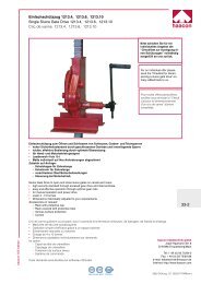
Elektrische Seilwinde Typ ESF / ESG Electrical rope ... - Haacon.de
Elektrische Seilwinde Typ ESF / ESG Electrical rope ... - Haacon.de
Elektrische Seilwinde Typ ESF / ESG Electrical rope ... - Haacon.de

Create successful ePaper yourself
Turn your PDF publications into a flip-book with our unique Google optimized e-Paper software.
Betriebsanleitung<br />
(Originaltext)<br />
Operating Manual<br />
(Translation)<br />
Manuel d‘utilisation<br />
(Traduction)<br />
Manual <strong>de</strong> instrucciones<br />
(Traducción)<br />
Istruzioni per l‘uso<br />
(Traduzione)<br />
Manual <strong>de</strong> instruções <strong>de</strong> funcionamento<br />
(Tradução)<br />
DE<br />
GB<br />
FR<br />
ES<br />
IT<br />
PT<br />
Competence in lifting technology<br />
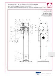
<strong>Elektrische</strong> <strong>Seilwin<strong>de</strong></strong> <strong>Typ</strong> <strong>ESF</strong> / <strong>ESG</strong><br />
<strong>Electrical</strong> <strong>rope</strong> winch type<br />
Treuil à câble électrique type<br />
Torno <strong>de</strong> cable eléctrico tipo<br />
Argano a fune elettrico tipo<br />
Guincho <strong>de</strong> cabo eléctrico tipo<br />
haacon hebetechnik gmbh<br />
Josef-Haamann-Str. 6<br />
D-97896 Freu<strong>de</strong>nberg/Main<br />
Tel: +49 (0) 93 75/84-0<br />
Fax: +49 (0) 93 75/84-66<br />
e-mail: haacon@haacon.<strong>de</strong><br />
Internet: www.haacon.com<br />
094278_g_<strong>de</strong>_gb_fr_es_it_pt_eseilwi_s haacon hebetechnik gmbh – Telefon +49 (0) 9375 - 84-0 – Fax +49 (0) 9375 - 84-66 1
DE<br />
Inhaltsverzeichnis<br />
1. Allgemeines........................................................................2<br />
1.1 Angaben zur Betriebsanleitung.....................................2<br />
1.2 Maschinentyp, Serie, Baujahr.......................................2<br />
1.3 Hersteller, Serviceadresse............................................2<br />
1.4 Bestimmungsgemäße Verwendung..............................2<br />
2. Sicherheitshinweise..........................................................3<br />
2.1 Allgemeine Sicherheitshinweise....................................3<br />
2.2 Sicherheitshinweise Betreiber.......................................3<br />
2.3 Sicherheitshinweise Bediener.......................................4<br />
2.4 Sichere Lagerung, Transport und Montage..................4<br />
2.5 Sichere Wartung / Instandhaltung,<br />
Störungsbeseitigung.....................................................4<br />
2.6 Sicherheitshinweise Elektrik..........................................5<br />
2.7 Lärmschutz.....................................................................5<br />
3. Produktbeschreibung.......................................................5<br />
3.1 Aufbau <strong>Typ</strong> <strong>ESF</strong>..............................................................5<br />
3.2 Aufbau <strong>Typ</strong> <strong>ESG</strong>.............................................................5<br />
3.3 Technische Daten..........................................................6<br />
4. Montage..............................................................................7<br />
4.1 Befestigung....................................................................7<br />
4.2 Einbaulage, Getriebeentlüftung....................................7<br />
4.3 Seile................................................................................7<br />
4.3.1 Allgemeines................................................................7<br />
4.3.2 Seilbefestigung an <strong>de</strong>r Trommel................................7<br />
4.3.3 Seilverlauf...................................................................7<br />
4.3.4 Seilendverbindungen.................................................8<br />
4.4 Lasthaken.......................................................................8<br />
5. Inbetriebnahme.................................................................8<br />
5.1 Netzanschluss................................................................8<br />
5.2 Min<strong>de</strong>stanfor<strong>de</strong>rungen..................................................8<br />
5.3 Optionen.........................................................................8<br />
6. Betrieb.................................................................................9<br />
7. Prüfung, Wartung, Instandhaltung.................................9<br />
7.1 Inspektionsintervalle......................................................9<br />
7.2 Prüfung vor Erstinbetriebnahme und nach wesentlichen<br />
Än<strong>de</strong>rungen vor Wie<strong>de</strong>rinbetriebnahme......................9<br />
7.3 Wie<strong>de</strong>rkehren<strong>de</strong> Prüfung...............................................9<br />
7.4 Ermittlung <strong>de</strong>s Nutzungsdauerverbrauchs...................10<br />
7.5 Überprüfung Seil............................................................10<br />
7.6 Überprüfung Lasthaken.................................................10<br />
7.7 Bremsmotor...................................................................10<br />
7.8 Getriebe.........................................................................10<br />
8. Optionen.............................................................................10<br />
8.1 Endabschaltung.............................................................10<br />
8.2 Andruckrolle...................................................................11<br />
8.3 Schlaffseilschalter..........................................................11<br />
8.4 Nothandantrieb..............................................................11<br />
8.5 Trommelfreischaltung....................................................11<br />
8.6 Steuerung mit Hängetaster, direkt................................12<br />
8.8 Steuerung, indirekt, mit elektrischem Lastbegrenzer ..12<br />
8.9 Steuerung indirekt, mit Halbleiter-Wen<strong>de</strong>schütz.........12<br />
9. Behebung von Störungen................................................13<br />
10. Außerbetriebnahme........................................................13<br />
11. ................................................... 74<br />
Anhang A.....................................................................79<br />
Konformitätserklärung..................................................82<br />
Einbauerklärung...........................................................85<br />
1. ALLGEMEINES<br />
1.1 Angaben zur Betriebsanleitung<br />
Der Inhalt ist Grundlage für sicheren, sachgerechten und<br />
wirtschaftlichen Betrieb. Sie enthält wichtige Hinweise über<br />
Aufbau, Inbetriebnahme, Bedienung, Betrieb und Wartung.<br />
Die Betriebsanleitung muss am Gerät verfügbar sein. Personen,<br />
die mit Arbeiten mit/am Gerät beauftragt sind, z.B.:<br />
––<br />
Bedienung, Pflege<br />
––<br />
Störungsbeseitigung<br />
––<br />
Wartung und Instandhaltung<br />
––<br />
Transport<br />
müssen <strong>de</strong>n Inhalt kennen und danach han<strong>de</strong>ln.<br />
Symbole in <strong>de</strong>r Betriebsanleitung:<br />
Gefahr für Leben und Gesundheit von Personen, Gerät und<br />
Material<br />
Gefahr durch schweben<strong>de</strong> Lasten für Leben und Gesundheit<br />
von Personen<br />
Gefahr durch elektrischen Strom für Leben und Gesundheit<br />
von Personen<br />
Gefahr durch Einziehen von Gliedmaßen<br />
Personenbeför<strong>de</strong>rung verboten<br />
Hinweise und Anwendungstipps<br />
1.2 Maschinentyp, Serie, Baujahr<br />
Das <strong>Typ</strong>schild zur I<strong>de</strong>ntifikation <strong>de</strong>r <strong>Seilwin<strong>de</strong></strong> :<br />
1.3 Hersteller, Serviceadresse<br />
<strong>Typ</strong>bezeichnung - Muster /<br />
Artikel-Nummer<br />
Kun<strong>de</strong>nnummer (KVG)/Position<br />
Serien Nummer<br />
haacon hebetechnik gmbh Tel.: +49 (0) 9375-84 0<br />
Josef-Haamann-Straße 6 Fax: +49 (0) 9675-84 66<br />
D 97896 Freu<strong>de</strong>nberg/Main e-mail: info@haacon.<strong>de</strong><br />
Internet: www.haacon.com<br />
1.4 Bestimmungsgemäße Verwendung<br />
Für sicheren Betrieb nur bestimmungsgemäß verwen<strong>de</strong>n.<br />
Für Personen- und Sachschä<strong>de</strong>n, die aus nicht bestimmungsgemäßer<br />
Verwendung entstehen, ist <strong>de</strong>r Betreiber<br />
verantwortlich. Durch eigenmächtige Verän<strong>de</strong>rungen<br />
erlischt Haftung und Gewährleistung <strong>de</strong>s Herstellers.<br />
––<br />
nur geeignet zum Heben, Senken und Ziehen von frei beweglichen<br />
Lasten.<br />
––<br />
Hebewin<strong>de</strong>n nur zum Heben und Senken von Lasten in <strong>de</strong>r<br />
Vertikalen und auf schiefen Ebenen einsetzen.<br />
––<br />
Zugwin<strong>de</strong>n nur zum Bewegen von Lasten auf horizontaler<br />
Ebene einsetzen.<br />
––<br />
Nur in technisch einwandfreiem Zustand benutzen.<br />
––<br />
Nur durch eingewiesenes Personal aufstellen, bedienen und<br />
warten.<br />
––<br />
Anschlusskonstruktion ausreichend dimensionieren.<br />
––<br />
Win<strong>de</strong> verzugsfrei befestigen.<br />
––<br />
auskuppelbare Trommeln sind nur zulässig bei Fahrzeugbergewin<strong>de</strong>n,<br />
Win<strong>de</strong>n für Bootsanhänger und Zugwin<strong>de</strong>n.<br />
Alle Unterlagen sind im Sinne <strong>de</strong>s Urheberrechtgesetzes geschützt. Alle Rechte zur Ausübung<br />
von gewerblichen Schutzrechten vorbehalten.<br />
094278_g_<strong>de</strong>_gb_fr_es_it_pt_eseilwi_s haacon hebetechnik gmbh – Telefon +49 (0) 9375 - 84-0 – Fax +49 (0) 9375 - 84-66 2
––<br />
Nicht erlaubt ist:<br />
––<br />
Überschreiten <strong>de</strong>r zulässigen Belastung (siehe <strong>Typ</strong>en-,<br />
Traglastschild und technische Daten).<br />
––<br />
Beför<strong>de</strong>rn von Personen.<br />
––<br />
Aufenthalt von Personen unter schweben<strong>de</strong>r Last.<br />
––<br />
Losreißen festsitzen<strong>de</strong>r o<strong>de</strong>r verklemmter Lasten, Schleifen<br />
von Lasten und Schrägzug.<br />
––<br />
Beför<strong>de</strong>rn feuerflüssiger Massen.<br />
––<br />
Arbeiten mit <strong>de</strong>fekter Win<strong>de</strong>, Seil o<strong>de</strong>r Lastaufnahmemittel.<br />
––<br />
Arbeiten außerhalb <strong>de</strong>s zulässigen Temperaturbereichs.<br />
––<br />
Einsatz in tropischer Umgebung.<br />
Verwendungsbereich:<br />
––<br />
Die Win<strong>de</strong> entspricht <strong>de</strong>r EN 14492-1 „Kraftgetriebene Win<strong>de</strong>n“<br />
sowie <strong>de</strong>r Unfallverhütungsvorschrift BGV D8 „Win<strong>de</strong>n,<br />
Hub und Zuggeräte“.<br />
Nicht zugelassen für<br />
––<br />
Bauaufzüge (BGV D7).<br />
––<br />
Bühnen und Studios (BGV C1).<br />
––<br />
Beför<strong>de</strong>rn von Lasten oberhalb von Leitungen und Rohren,<br />
durch die brennbare o<strong>de</strong>r gesundheitsschädliche Gase<br />
o<strong>de</strong>r Flüssigkeiten geleitet wer<strong>de</strong>n mit Steuerungen <strong>de</strong>r<br />
Sicherheitskategorie 2.<br />
––<br />
hochziehbare Personenaufnahmemittel (ZH 1/461).<br />
––<br />
Verwendung in explosionsgefähr<strong>de</strong>ter Umgebung (ATEX).<br />
Ungeeignet für<br />
––<br />
Dauerbetrieb (siehe technische Daten, Triebwerksgruppe).<br />
––<br />
übermäßigen Tippbetrieb.<br />
––<br />
Einsatz bei ständiger Vibration.<br />
––<br />
Verwendung auf hochseefähigen Schiffen und mobilen<br />
Offshore-Einrichtungen.<br />
––<br />
aggressive Umgebung.<br />
––<br />
Forstwirtschaft.<br />
Eingeschränkt geeignet für (geson<strong>de</strong>rte Auslegung):<br />
––<br />
stationäre Offshore-Einrichtungen<br />
2. SICHERHEITSHINWEISE<br />
2.1 Allgemeine Sicherheitshinweise<br />
Das Gerät entspricht in allen Belangen <strong>de</strong>n einschlägigen Vorschriften.<br />
Dennoch können bei <strong>de</strong>ssen Verwendung Gefahren<br />
für <strong>de</strong>n Benutzer o<strong>de</strong>r Dritte bzw. Schä<strong>de</strong>n am Gerät und<br />
an<strong>de</strong>ren Sachwerten entstehen, bei:<br />
––<br />
nicht eingewiesenem (geschultem) Personal.<br />
––<br />
nicht bestimmungsgemäßem Einsatz.<br />
––<br />
unsachgemäßer Wartung / Instandhaltung.<br />
Auch bei Beachtung aller Sicherheitsbestimmungen verbleiben<br />
gewisse Restrisiken. Wer mit <strong>de</strong>m Gerät o<strong>de</strong>r in <strong>de</strong>ssen<br />
Umfeld arbeitet, muss diese Gefahren kennen und Anweisungen<br />
befolgen, die verhin<strong>de</strong>rn, dass Restrisiken zu Unfällen<br />
o<strong>de</strong>r Schä<strong>de</strong>n führen.<br />
Die Restrisiken sind mit Symbolen gekennzeichnet (Erklärung<br />
in Kapitel 1.1).<br />
Die Konformitätserklärung im Anhang gilt nur für vollständige<br />
Maschinen bei Lieferung aller Komponenten durch<br />
Fa. haacon. Ansonsten obliegt es <strong>de</strong>m Hersteller <strong>de</strong>r Gesamtanlage,<br />
die Konformität zu erklären.<br />
Sicherheitseinrichtungen<br />
Sicherheitseinrichtungen regelmäßig auf einwandfreie Funktion<br />
prüfen (--> auch Kapitel 7 und 8):<br />
<br />
<br />
<br />
<br />
1 Haltebremse Überprüfung vor je<strong>de</strong>m Arbeitsbeginn<br />
2 Endabschaltung Vorgeschrieben nach EN 14492-1; Einstellen<br />
vor Erstinbetriebnahme; regelmäßige<br />
Überprüfung<br />
3 Andruckrolle regelmäßige Überprüfung<br />
4 Schlaffseilschalter Einstellen vor Erstinbetriebnahme; regelmäßige<br />
Überprüfung<br />
5 Lastbegrenzer,<br />
Überlastsicherung<br />
6 Motorabschaltung<br />
bei Nothandantrieb<br />
7 Motorabschaltung bei<br />
ausgekuppelter Trommel<br />
<br />
<br />
Vorgeschrieben nach EN 14492-1 bei Lasten<br />
≥ 1000 kg; Einstellen vor Erstinbetriebnahme;<br />
regelmäßige Überprüfung<br />
Einstellen vor Erstinbetriebnahme;<br />
Überprüfung vor Benutzung und nach<br />
Prüfplan<br />
<br />
<br />
Einstellen vor Erstinbetriebnahme;<br />
regelmäßige Überprüfung<br />
8 Schalter „Not-Aus“ regelmäßige Überprüfung<br />
Nr. 2, 3, 4, 5 ,6 ,7 ,8 optional<br />
2.2 Sicherheitshinweise Betreiber<br />
Es ist Sorgfaltspflicht <strong>de</strong>s Betreibers, alle erfor<strong>de</strong>rlichen Maßnahmen<br />
zur Gewährleistung <strong>de</strong>r Sicherheit zu planen und zu<br />
überwachen.<br />
Sicherstellen dass:<br />
––<br />
<strong>de</strong>r Einsatz bestimmungsgemäß ist (Kapitel 1.4).<br />
––<br />
die Sicherheit <strong>de</strong>s Gerätes entsprechend seinen Einsatzund<br />
Umgebungsbedingungen analysiert wird und erkennbare<br />
Risiken (z.B. Verletzungsgefahr am Seileingang und an<br />
rotieren<strong>de</strong>r Trommel) beurteilt und beseitigt wer<strong>de</strong>n.<br />
––<br />
vor Erstinbetriebnahme nach <strong>de</strong>n entsprechen<strong>de</strong>n internationalen<br />
und nationalen Vorschriften geprüft und freigegeben<br />
wird.<br />
––<br />
<strong>de</strong>r Betrieb nur in einwandfreiem, funktionstüchtigem Zustand<br />
erfolgt.<br />
––<br />
die Sicherheitseinrichtungen regelmäßig auf ihre Wirksamkeit<br />
überprüft wer<strong>de</strong>n nur Seile verwen<strong>de</strong>t wer<strong>de</strong>n, die einer<br />
gültigen Norm entsprechen und für <strong>de</strong>n Einsatzfall geeignet<br />
sind. (Kapitel 4.3)<br />
––<br />
die erfor<strong>de</strong>rliche, persönliche Schutzausrüstung für das<br />
Montage-, Bedienungs-, Wartungs- und Reparaturpersonal<br />
zur Verfügung steht und benutzt wird.<br />
––<br />
die Betriebsanleitung stets in einem leserlichen Zustand und<br />
vollständig am Einsatzort <strong>de</strong>s Gerätes zur Verfügung steht.<br />
DE<br />
094278_g_<strong>de</strong>_gb_fr_es_it_pt_eseilwi_s haacon hebetechnik gmbh – Telefon +49 (0) 9375 - 84-0 – Fax +49 (0) 9375 - 84-66 3
––<br />
nur qualifiziertes und autorisiertes Personal das Gerät bedient,<br />
wartet, prüft und repariert.<br />
––<br />
dieses Personal regelmäßig in allen zutreffen<strong>de</strong>n Fragen<br />
<strong>de</strong>r Arbeitssicherheit und <strong>de</strong>s Umweltschutzes unterwiesen<br />
wird, sowie die Betriebsanleitung und beson<strong>de</strong>rs die darin<br />
enthaltenen Sicherheitshinweise kennt.<br />
––<br />
die zulässige Last für <strong>de</strong>n Bediener <strong>de</strong>utlich erkennbar ist.<br />
––<br />
Schil<strong>de</strong>r am Gerät nicht entfernt wer<strong>de</strong>n und lesbar bleiben.<br />
––<br />
keine wesentlichen Verän<strong>de</strong>rungen am Gerät vorgenommen<br />
wer<strong>de</strong>n.<br />
––<br />
vorgeschriebene Prüfungen durchgeführt und dokumentiert<br />
DE wer<strong>de</strong>n.<br />
––<br />
zur Verwendung kommen<strong>de</strong> Ersatz- und Verschleißteile <strong>de</strong>n<br />
vom Hersteller festgelegten technischen Anfor<strong>de</strong>rungen<br />
entsprechen. Dies ist bei Originalersatzteilen gewährleistet.<br />
2.3 Sicherheitshinweise Bediener<br />
Personen, die das Gerät selbstständig bedienen, müssen hierzu<br />
geeignet, mit <strong>de</strong>n gelten<strong>de</strong>n Sicherheits- und Unfallverhütungsvorschriften<br />
vertraut und vom Betreiber beauftragt sein.<br />
Gerät nur in technisch einwandfreiem Zustand sowie bestimmungsgemäß<br />
(Kapitel1.4), sicherheits- und gefahrenbewusst<br />
unter Beachtung <strong>de</strong>r Betriebsanleitung nutzen.<br />
Checken Sie:<br />
• z Sind die notwendigen Sicherheitseinrichtungen (Kapitel<br />
2.1) vorhan<strong>de</strong>n und funktionsfähig?<br />
• z Ist die Funktion <strong>de</strong>r Bremse vor je<strong>de</strong>m Arbeitsbeginn geprüft?<br />
• z Wird persönliche Schutzausrüstung getragen, soweit die<br />
örtlichen Bestimmungen dies vorsehen?<br />
• z Ist das Lastaufnahmemittel und Seil vor je<strong>de</strong>m Arbeitsbeginn,<br />
sowie regelmäßig das komplette Gerät einer Sichtprüfung<br />
unterzogen wor<strong>de</strong>n?<br />
––<br />
Nicht fahrlässig vorgehen!<br />
• z Mangelhaftes Gerät sofort stillsetzen und Vorgesetzten<br />
informieren.<br />
• z Erst Mängel beseitigen, dann weiterarbeiten.<br />
• z Beschädigte Lastaufnahmemittel und Seile austauschen.<br />
Reparaturen sind unzulässig.<br />
––<br />
Nur Originalersatzteile verwen<strong>de</strong>n.<br />
––<br />
Keine Verän<strong>de</strong>rungen und Umbauten am Gerät vornehmen.<br />
Anbauten dürfen we<strong>de</strong>r Sicherheit noch Funktion beeinträchtigen.<br />
Verboten:<br />
Personentransport<br />
Aufenthalt von Personen unter angehobener Last.<br />
Hinweis: Personen in unmittelbarer Nähe warnen.<br />
Wir verweisen auf die einschlägigen Bestimmungen<br />
<strong>de</strong>r Unfallverhütungsvorschriften und beim Einsatz<br />
außerhalb Deutschlands auf die jeweiligen nationalen<br />
Vorschriften.<br />
Berühren von Trommel und Seileinlauf während <strong>de</strong>s<br />
Betriebes.<br />
Arbeiten an spannungsführen<strong>de</strong>n Bauteilen.<br />
Niemals:<br />
––<br />
Last mit Hubseil umschlingen.<br />
––<br />
Hubseil über feststehen<strong>de</strong> Teile o<strong>de</strong>r Kanten ziehen.<br />
––<br />
zulässige Tragfähigkeit überschreiten.<br />
––<br />
Sicherheitseinrichtungen manipulieren.<br />
––<br />
Lasten schrägziehen und schleifen.<br />
––<br />
festsitzen<strong>de</strong> Lasten losreißen.<br />
––<br />
Seil bis zur Seilbefestigung abspulen. Zwei Windungen<br />
müssen immer auf <strong>de</strong>r Trommel verbleiben.<br />
––<br />
mit ungespanntem Seil arbeiten ohne Sicherung gegen<br />
Aufspringen von <strong>de</strong>r Trommel.<br />
––<br />
Arbeiten ohne Hubbegrenzung.<br />
Zur Betriebssicherheit vermei<strong>de</strong>n:<br />
––<br />
Dauerbetrieb, sowie ständiger Tippbetrieb, Überschreiten<br />
<strong>de</strong>r Einschaltdauer <strong>de</strong>r Motoren, sowie Restlebensdauer<br />
gemäß Triebwerksgruppe und Beanspruchung.<br />
Vor Anheben <strong>de</strong>r Last prüfen:<br />
• z Ist die Last sicher im Lasthaken eingehängt und liegt sie im<br />
Hakengrund auf? Ist die Sicherungsklappe geschlossen?<br />
Für das Anschlagen <strong>de</strong>r Last gelten die jeweiligen nationalen<br />
Bestimmungen für Lastaufnahmeeinrichtungen<br />
(In Deutschland die BGR 500, Kap. 2.8).<br />
2.4 Sichere Lagerung, Transport und Montage<br />
Sauber, trocken und geschützt lagern. Maßnahmen gegen Korrosion<br />
beson<strong>de</strong>rs an Drahtseil, Haken und Bremse ergreifen.<br />
Transport und Montage durch autorisierte Personen, vertraut<br />
mit <strong>de</strong>n gelten<strong>de</strong>n Sicherheits- und Unfallverhütungsvorschriften<br />
und <strong>de</strong>r Betriebsanleitung.<br />
Checken Sie:<br />
• z Sind Transportschä<strong>de</strong>n vorhan<strong>de</strong>n? (Unverzüglich <strong>de</strong>m<br />
Lieferanten anzeigen).<br />
• z Wird persönliche Schutzausrüstung getragen? (Schutzhandschuhe,<br />
Sicherheitsschuhe, gegebenenfalls Schutzhelm).<br />
• z Wer<strong>de</strong>n geeignete, genormte und geprüfte Hebezeuge und<br />
Anschlagmittel verwen<strong>de</strong>t? Abmessungen und Gewichte<br />
--> technische Daten (Kapitel 3.3).<br />
Stets:<br />
––<br />
Anschlagmittel nur an Grundplatte, Getriebe, Trommel und/<br />
o<strong>de</strong>r Trommelwelle befestigen.<br />
––<br />
Gerät schlag- und stoßfrei transportieren, gegen Umfallen<br />
o<strong>de</strong>r Umkippen sichern.<br />
––<br />
Auf tragfähiger, ebener Unterlage montieren.<br />
––<br />
Gerät so befestigen, dass we<strong>de</strong>r die Last, noch an<strong>de</strong>re<br />
Einflüsse die Stellung verän<strong>de</strong>rn.<br />
2.5 Sichere Wartung / Instandhaltung, Störungsbeseitigung<br />
Vorgeschriebene o<strong>de</strong>r in <strong>de</strong>r Betriebsanleitung angegebene<br />
Fristen für wie<strong>de</strong>rkehren<strong>de</strong> Prüfungen/Inspektionen einhalten.<br />
Personen, die am Gerät arbeiten müssen hierzu geeignet, mit<br />
<strong>de</strong>n gelten<strong>de</strong>n Sicherheits- und Unfallverhütungsvorschriften<br />
vertraut und vom Betreiber beauftragt sein.<br />
Bevor Sie Son<strong>de</strong>r- und Instandhaltungsmaßnahmen ergreifen:<br />
• z Sind Personen im Gefahrenbereich informiert und gewarnt?<br />
Bereiche abgesperrt?<br />
• z Ist das Gerät lastfrei und ausreichend abgekühlt?<br />
Ist <strong>de</strong>r Hauptschalter ausgeschaltet und das Gerät<br />
gegen unerwartetes Wie<strong>de</strong>reinschalten gesichert?<br />
(Not-Aus betätigen, Hauptschalter abschließen<br />
und Warnschild anbringen) Manuelle Eingriffe bei<br />
laufen<strong>de</strong>m Gerät können zu schweren Unfällen<br />
führen. Ist Einschalten <strong>de</strong>nnoch erfor<strong>de</strong>rlich (z.B.<br />
Seilwechsel) so darf dies nur unter Einhaltung beson<strong>de</strong>rer<br />
Sicherheitsmaßnahmen erfolgen.<br />
––<br />
Wird geeignete Schutzausrüstung getragen und sind je<br />
nach Einsatzfall geeignete Schutzmaßnahmen getroffen?<br />
(z.B. Absturzsicherungen bei Arbeiten in großer Höhe)<br />
094278_g_<strong>de</strong>_gb_fr_es_it_pt_eseilwi_s haacon hebetechnik gmbh – Telefon +49 (0) 9375 - 84-0 – Fax +49 (0) 9375 - 84-66 4
––<br />
Sind evtl. gelöste Schraubverbindungen wie<strong>de</strong>r sicher<br />
festgezogen?<br />
––<br />
Sind bei erfor<strong>de</strong>rlicher Demontage von Sicherheitseinrichtungen<br />
unmittelbar nach Abschluss <strong>de</strong>r Arbeiten die Montage<br />
und Überprüfung <strong>de</strong>rselben erfolgt und dokumentiert?<br />
––<br />
Sind Betriebs- und Hilfsstoffe sicher und umweltschonend<br />
entsorgt?<br />
2.6 Sicherheitshinweise Elektrik<br />
Bei Arbeiten an elektrischer Anlage Gerät vom Netz trennen.<br />
Arbeiten an elektrischen Ausrüstungen nur durch autorisierte<br />
Fachkräfte ausführen. Elektrofachkraft ist eine Person mit<br />
geeigneter Ausbildung und Erfahrung, sowie Kenntnis <strong>de</strong>r<br />
einschlägigen Bestimmungen, die in <strong>de</strong>r Lage ist, Risiken zu<br />
erkennen und Gefahren zu vermei<strong>de</strong>n, die von <strong>de</strong>r Elektrizität<br />
ausgehen können.<br />
Schaltschränke stets verschlossen halten.<br />
Niemals:<br />
an spannungsführen<strong>de</strong>n Teilen arbeiten.<br />
Bei Inspektions-, Wartungs- und Reparaturarbeiten:<br />
• z Gerät vom Netz trennen, gegen Wie<strong>de</strong>reinschalten sichern<br />
• z <strong>Elektrische</strong> Bauteile zuerst auf Spannungsfreiheit prüfen,<br />
dann er<strong>de</strong>n und kurzschließen, sowie benachbarte unter<br />
Strom stehen<strong>de</strong>n Bauteile isolieren.<br />
• z zweite Person hinzuziehen, die bei Arbeiten an spannungsführen<strong>de</strong>n<br />
Bauteilen (Ausnahmesituation) im Notfall <strong>de</strong>n<br />
Not-Aus-Taster o<strong>de</strong>r Hauptschalter betätigt. Nur spannungsisoliertes<br />
Werkzeug verwen<strong>de</strong>n.<br />
––<br />
Sicherungen stets ersetzen durch Sicherungen <strong>de</strong>s gleichen<br />
<strong>Typ</strong>s mit vorgeschriebener Stromstärke.<br />
––<br />
Sicherungen niemals überbrücken!<br />
––<br />
An Steuerungen keine konstruktiven und sicherheitsmin<strong>de</strong>rn<strong>de</strong>n<br />
Verän<strong>de</strong>rungen vornehmen.<br />
––<br />
Die einwandfreie Erdung <strong>de</strong>s elektrischen Systems durch<br />
ein Schutzleitersystem gewährleisten.<br />
2.7 Lärmschutz<br />
Lärm stellt bei diesem Gerät keine signifikante Gefahr dar.<br />
Werte --> technische Daten (Kapitel 3.3).<br />
Entsprechend <strong>de</strong>n örtlichen Gegebenheiten kann Gehörschutz<br />
<strong>de</strong>nnoch erfor<strong>de</strong>rlich sein.<br />
3. PRODUKTBESCHREIBUNG<br />
Serienmässige Anordnung von Trommeldrehrichtung und Seilabgang<br />
--> technische Daten (Kapitel 3.3). Kann bei kun<strong>de</strong>nspezifischer<br />
Ausführung abweichen. (--> Kapitel 4.3.3).<br />
90°<br />
90°<br />
optional:<br />
d<br />
e<br />
f<br />
g<br />
h<br />
i<br />
j<br />
e<br />
j<br />
h/i<br />
Gerillte Trommel<br />
Endabschaltung<br />
Befestigungsplatte mit Andruckrolle<br />
Schlaffseilschalter<br />
Steuerung (direkt, indirekt) mit Hängetaster<br />
Steuerung mit Hängetaster und elektrischer Lastbegrenzung<br />
Nothandantrieb<br />
3.2 Aufbau <strong>Typ</strong> <strong>ESG</strong><br />
d<br />
c<br />
a Getriebe mit Befestigungsbohrungen<br />
b Bremsmotor (400 V bzw. 230 V)<br />
c Trommel, glatt<br />
d Grundplatte mit Außenlager<br />
optional:<br />
f<br />
i/j<br />
k<br />
b<br />
e<br />
g<br />
h<br />
g<br />
a<br />
f<br />
d<br />
DE<br />
180°<br />
270°<br />
0°<br />
rechtsdrehend (re)<br />
180°<br />
0°<br />
270°<br />
linksdrehend (li)<br />
Bei Win<strong>de</strong>n mit 230 V AC - Steuerung kann die Drehrichtung<br />
nicht geän<strong>de</strong>rt wer<strong>de</strong>n. Bei <strong>de</strong>n übrigen Win<strong>de</strong>n kann<br />
die Trommeldrehrichtung durch Än<strong>de</strong>rn <strong>de</strong>r Phasenlage am<br />
Netzanschluss erfolgen.<br />
3.1 Aufbau <strong>Typ</strong> <strong>ESF</strong><br />
e Gerillte Trommel<br />
f Endabschaltung<br />
g Andruckrolle<br />
h Schlaffseilschalter<br />
i Steuerung (direkt, indirekt) mit Hängetaster<br />
j Steuerung mit Hängetaster und elektrischer Lastbegrenzung<br />
k Nothandantrieb<br />
Als Son<strong>de</strong>rausführung möglich:<br />
m<br />
l<br />
c<br />
b<br />
a<br />
a<br />
b<br />
c<br />
Getriebe mit Befestigungsbohrungen<br />
Bremsmotor (400 V bzw.<br />
230 V)<br />
Trommel, glatt<br />
l<br />
m<br />
Geteilte Trommel<br />
Auskuppelbare Trommel<br />
094278_g_<strong>de</strong>_gb_fr_es_it_pt_eseilwi_s haacon hebetechnik gmbh – Telefon +49 (0) 9375 - 84-0 – Fax +49 (0) 9375 - 84-66 5
DE<br />
3.3 Technische Daten<br />
Elektro - <strong>Seilwin<strong>de</strong></strong> <strong>Typ</strong> <strong>ESF</strong> Elektro - <strong>Seilwin<strong>de</strong></strong> <strong>Typ</strong> <strong>ESG</strong><br />
Spannung [V] 400 230 400 230<br />
Nennlast [kg] 150 250 500 200 400 150 250 500 750 990 1500 2100 200 400 650 1100<br />
Verwendung 8 ABC AB ABC ABC ABC ABC ABC ABC AB ABC ABC ABC ABC AB ABC ABC AB ABC ABC ABC ABC ABC ABC ABC ABC ABC ABC ABC ABC ABC ABC<br />
Seilzugkraft [kN] 1,5 2,5 5 2 4 1,5 2x0,75 2,5 2x1,25 5 2x2,5 7,5 2x3,75 9,9 2x4,95 15 2x7,5 21 2x10,5 2 2x1 4 2x2 6,5 2x3,25 11 2x5,5<br />
Seilaufnahme [m] 3,4 2,8 3,4 3,2 3,4 3,2 10 2x5 8 10 2x5 10,5 2x6 12 12,5 2x7 12 14 2x7 14 2x8 14 2x8 10 2x5 10,5 2x6 14 2x7 17 2x8<br />
7,2 7,2 7 7,5 7,2 7,5 7,2 7,2 7,2 7,2 7,2 7,5 7,4 5,1 5,1 5,1 4,2 4,2 4,2 5 5 5 5 7,2 7,2 7,5 7,4 4,2 4,2 5 5<br />
Seilgeschwindigkeit [m/<br />
min]<br />
1. Seillage<br />
Seilzugkraft [kN] 1,35 2,0 2,05 4.4 1,8 3,55 1,35 2x0,67 2,2 2,25 2x1,12 4,4 2x2,2 6,6 6,7 2x3,3 8,7 8,8 2x4,4 13,4 2x6,8 18,5 2x9,3 1,8 2x0,9 3,55 2x1,8 5,8 2x2,9 10 2x5<br />
Seilaufnahme [m] 7,3 6 7,3 7 7,3 7 22 2x10 18 22 2x10 22 2x12 27 31 2x14,5 27 30 2x14,5 30 2x17 30 2x17 22 2x10 22 2x12 30 2x14,5 35 2x17<br />
7,9 8,2 7,8 8,5 7,8 8,5 7,9 7,9 8,2 7,8 7,8 8,5 8,2 5,8 5,7 5,7 4,7 4,7 4,7 5,5 5,4 5,5 5,4 7,9 7,9 8,5 8,2 4,7 4,7 5,4 5,4<br />
Seilgeschwindigkeit [m/<br />
min]<br />
2. Seillage<br />
Seilzugkraft [kN] 1,25 2 2,05 4 1,65 3.2 1,25 2x0,62 2 2,05 2x1 4 2x2 5,9 6 2x3 7,75 8 2x4 12 2x6,2 16,5 2x8,3 1,65 2x0,82 3,2 2x1,65 5,3 2x2,6 9,1 2x4,5<br />
Seilaufnahme [m] 11,5 9,6 11,5 11 11,5 11 34 2x16 28 34 2x16 35 2x20 43 49 2x23 43 48 2x23 45 2x26,5 45 2x26,5 34 2x16 35 2x20 48 2x23 56 2x26,5<br />
8,6 9,1 8,6 9,4 8,6 9,4 8,6 8,6 9,1 8,6 8,6 9,4 9,4 6,5 6,3 6,3 5,3 5,2 5,0 6,1 5,9 6,1 5,9 8,6 8,6 9,4 9 5,3 5,1 5,9 5,9<br />
Seilgeschwindigkeit [m/<br />
min]<br />
3. Seillage<br />
maximale Lagenzahl 4 6 5 6 5 6 5 6 6 5 6 6 5 6 7 7 7 7 7 7 3 4 3 4 6 6 5 6 7 7 4 4<br />
Seilzugkraft [kN] 0,95 1,6 1,6 3,3 1.3 2,65 0,95 2x0,48 1,6 1,6 2x0,8 3,3 2x1,6 4,1 4,3 2x2,2 5,4 5,7 2x2,8 12 2x5,7 16,5 2x8 1,3 2x0,65 2,65 2x1,3 3,8 2x1,9 8,4 2x4,2<br />
Seilaufnahme [m] 26 17,8 26 20 26 20 79 2x38 53 79 2x38 65 2x45 126 138 2x66 126 138 2x66 45 2x37 45 2x37 79 2x38 65 2x45 138 2x66 76 2x37<br />
11 11 11 11 11 11 11 11 11 11 11 11 11 9 8,8 8,8 7,6 7,2 6,8 6,1 6,4 6,1 6,4 11 11 11 11 7,2 6,8 6,4 6,4<br />
Seilgeschwindigkeit [m/<br />
min]<br />
oberste<br />
Lage<br />
4 1 5 1 4 2 6 1 4 1 6 1 4 1 4 1 5 1 5 1 5 1 6 1 5 1 8 1 7 2 6 2 8 2 7 2 6 2 11 1 9 1 11 2 9 2 4 1 4 1 6 1 5 1 7 1 6 2 9 2 9 1<br />
nicht drehungsfreies Seil<br />
[mm]<br />
Min<strong>de</strong>stbruchkraft [kN] 8,3 13 8,7 18,7 8,3 18,7 8,3 8,3 13 8,7 8,3 18,7 13 33,4 26,6 18,7 34,8 31,4 18,7 60 42 71 52 8,3 8,3 18,7 13 25,5 18,7 52 42<br />
Seildurchmesser 6<br />
094278_g_<strong>de</strong>_gb_fr_es_it_pt_eseilwi_s haacon hebetechnik gmbh – Telefon +49 (0) 9375 - 84-0 – Fax +49 (0) 9375 - 84-66 6<br />
Triebswerksgruppe 5 2m 1Am 1Bm 1Bm 1Am 1Am 2m 2m 1Am 1Bm 2m 1Bm 2m 1Bm 1Bm 2m 1Bm 1Dm 1Am 1Am 1Am 1Cm 1Am 1Am 3m 1Am 2m 1Bm 1Am 1Am 2m<br />
drehungsarmes Seil [mm] 4 1 5 1 4 3 6 2 4 1 6 1 4 1 4 1 5 1 4 3 4 1 6 2 5 1 8 2 7 3 6 2 8 2 7 3 6 2 11 1 9 1 11 3 9 2 4 1 4 1 6 1 5 1 7 2 6 2 9 2 9 1<br />
Min<strong>de</strong>stbruchkraft [kN] 8,3 13 10,3 20,9 8,3 18,7 8,3 8,3 13 10,3 8,3 20,9 13 37,2 31,5 20,9 37,2 31,5 20,9 71 42 72 52 8,3 8,3 18,7 13 25,5 20,9 52 42<br />
Triebswerksgruppe 5 1Am 1Bm 1Bm 1Bm 1Bm 1Bm 1Am 1Am 1Bm 1Bm 1Am 1Bm 1Am 1Bm 1Bm 1Am 1Cm 1Dm 1Bm 1Bm 1Am 1Cm 1Bm 1Bm 2m 1Bm 2m 1Bm 1Am 1Bm 1Am<br />
Trommeldrehrichtung Serie re re re re re re re re re li li re re li li<br />
Motorleistung [kW] 0.37 0,55 1,1 0,55 1,1 0.37 0,55 1,1 1,5 1,5 1,5 2,2 0,55 1,1 1,1 1,1<br />
Nennstrom [A] 1,07 1,43 2,82 4,5 7,5 1,07 1,43 2,82 3,8 3,8 3,8 5,4 4,5 7,5 7,5 7,5<br />
Schutzart min. IP 54 min. IP 54<br />
S3-40 % mit 120 c/h o<strong>de</strong>r S2-12 min<br />
Einschaltdauer S3-40 % mit 120 c/h o<strong>de</strong>r S2-12<br />
min<br />
Geräuschpegel [dB(A)] ≤ 70 ≤ 75 ≤ 83 7 ≤ 70 ≤ 72 ≤ 83 7 ≤ 83 7 ≤ 72<br />
18 21,5 38 23 43,5 29 32,5 52,5 90 98 193 198 34 58 100 195<br />
Gewicht [kg]<br />
ohne Seil, ohne Optionen<br />
<strong>Typ</strong> 150 250 500 200 400 150 250 500 750 990 1500 2100 200 400 650 1100<br />
Seilaufnahme für glatte Trommeln. Bei Verwendung gerillter Trommeln verringert sich die Seilaufnahme. 8) Verwendung<br />
1) Nennfestigkeit <strong>de</strong>r Einzeidrähte min. 1570 N/mm 2 . A = Hebewin<strong>de</strong>, Ziehen auf schräger Ebene<br />
2) Nennfestigkeit <strong>de</strong>r Einzeldrähte min. 1770 N/mm 2 . B = Boots-, Fahrzeugbergewin<strong>de</strong>n<br />
3) Nennfestigkeit <strong>de</strong>r Einzeldrähte min. 1960 N/mm 2 . C = Zugwin<strong>de</strong> (Ziehen auf waagrechter Ebene)<br />
4) Standardlagenzahl: 3<br />
5) Triebwerksgruppe nach DIN 15020 bzw. FEM 9.511.<br />
6) An<strong>de</strong>re Seildurchmesser auf Anfrage.<br />
7) Nur beim Senken unter Volllast. Beim Heben Geräuschpegel ≤ 70 dB(A). Ab 80 dB(A) ist Gehörschutz zur Verfügung zu stellen. geteilte Trommel<br />
Die Seilzugkraft ergibt sich aus allen an <strong>de</strong>r <strong>Seilwin<strong>de</strong></strong> befestigten Massen (z.B. Seil, Haken, Anschlagmittel, Hebegestelle, Magnete, Nutzlast)<br />
und gilt für Aufstellhöhen unter 1000 m bezogen auf Meereshöhe.<br />
Die 1. Seillage ist die direkt auf <strong>de</strong>r Trommel liegen<strong>de</strong> Seillage.
4. MONTAGE<br />
Es gelten die Sicherheitshinweise (Kapitel 2), insbeson<strong>de</strong>re für<br />
Lagerung, Transport und Montage (Kapitel 2.4).<br />
4.1 Befestigung<br />
––<br />
Anschlusskonstruktion: ausreichen<strong>de</strong> Festigkeit und Steifigkeit,<br />
um auftreten<strong>de</strong> Kräfte sicher aufzunehmen.<br />
––<br />
Anlagefläche eben, zum spannungsfreien Befestigen.<br />
––<br />
Schrauben gegen Selbstlockern sichern.<br />
Verschraubungsvorgaben:<br />
<strong>Typ</strong> Dim. Festigkeit<br />
Anzugsmoment<br />
[Nm]<br />
Anzahl<br />
<strong>ESF</strong> 150 / 200 / 250 M8 8.8 25 ≥ 4<br />
<strong>ESF</strong> 400 / 500 M10 8.8 50 ≥ 4<br />
<strong>ESG</strong> 150 / 200 / 250 M8 8.8 25 ≥ 4<br />
<strong>ESG</strong> 400 / 500 M10 8.8 50 ≥ 4<br />
<strong>ESG</strong> 700 / 750 / 990 M12 8.8 87 ≥ 5<br />
<strong>ESG</strong> 1100 / 1500 / 2100 M16 8.8 210 ≥ 5<br />
4.2 Einbaulage, Getriebeentlüftung<br />
• z Abhängig von <strong>de</strong>r Einbaulage nach Befestigen <strong>de</strong>r <strong>Seilwin<strong>de</strong></strong><br />
eine Verschlussschraube am Getriebe durch die mitgelieferte<br />
Entlüftungsschraube ersetzen.<br />
• z Bei Win<strong>de</strong>n <strong>de</strong>s <strong>Typ</strong>s <strong>ESF</strong>, sowie bei <strong>de</strong>n <strong>Typ</strong>en <strong>ESG</strong> 150 /<br />
200 / 250 / 400 und 500 Anschluss<strong>de</strong>ckel am Getriebe so<br />
drehen, dass die Entlüftung nach oben weist.<br />
<strong>Seilwin<strong>de</strong></strong>n <strong>de</strong>r Lastklasse über 600 kg wer<strong>de</strong>n auf ausdrückliche<br />
Bestellung auch ohne Ölfüllung geliefert. Ist keine Einbaulage<br />
vorgegeben, gilt Einbaulage B3. Bei Än<strong>de</strong>rung <strong>de</strong>r<br />
Einbaulage durch <strong>de</strong>n Anwen<strong>de</strong>r vor Inbetriebnahme Ölstand<br />
kontrollieren und gegebenenfalls anpassen.<br />
Die Einbaulage <strong>de</strong>r Win<strong>de</strong> ist durch die Lage <strong>de</strong>s Getriebes<br />
bestimmt. Folglich variieren die Position <strong>de</strong>r Entlüftung,<br />
<strong>de</strong>r Ölkontrolle, sowie die Ölfüllmenge (--> Anhang<br />
A und Benutzerhandbuch <strong>de</strong>s Herstellers).<br />
Die richtige Einbaulage ist Voraussetzung für einen<br />
sicheren Betrieb und einzuhalten.<br />
Einbaulage B6 und B7 (Trommelachse senkrecht) sind<br />
unzulässig, da ein sicheres Aufspulen <strong>de</strong>s Seils nicht<br />
gewährleistet ist.<br />
Zuordnung Getriebe zu Win<strong>de</strong> --> Ersatzteillisten.<br />
Einsatztemperatur:<br />
––<br />
zul. Temperaturbereich: –20°C bis +40°C.<br />
––<br />
Bei Temperaturen unter –10°C, zunächst Warmlaufen <strong>de</strong>r<br />
Win<strong>de</strong> ohne / mit reduzierter Last.<br />
––<br />
Bei Einsatz im Freien Win<strong>de</strong> vor Witterungseinflüssen schützen.<br />
Vorteilhaft ist ein Bremsmotor mit Schutzart IP 55. Bei<br />
senkrechter Einbaulage Motor mit Schutzdach versehen.<br />
––<br />
In beson<strong>de</strong>rs feuchter Umgebung und bei starken Temperaturschwankungen<br />
kann <strong>de</strong>r Motor zusätzlich mit einem Heizelement<br />
als Kon<strong>de</strong>nswasserschutz ausgestattet wer<strong>de</strong>n.<br />
Durch Kon<strong>de</strong>nsation (Feuchtigkeit, Temperaturschwankungen)<br />
kann es bei längeren Stillstandszeiten zu<br />
Korrosion an <strong>de</strong>r mechanischen Bremse und so zu<br />
Funktionsstörungen <strong>de</strong>r Bremse kommen. Auch ein<br />
Korrosionsschutz kann dies nicht vollständig verhin<strong>de</strong>rn.<br />
Am besten die Win<strong>de</strong> regelmäßig benutzen.<br />
Durch einen wöchentlichen Probelauf und mehrmaliges<br />
Einschalten <strong>de</strong>s Motors, kann ein Festsitzen <strong>de</strong>r<br />
Bremse nach unseren Erfahrungen verhin<strong>de</strong>rt wer<strong>de</strong>n.<br />
4.3 Seile<br />
4.3.1 Allgemeines<br />
––<br />
Wählen Sie ein für Ihre Zwecke geeignetes Seil.<br />
Auswahlhilfen bietet z.B. die EN 12385-3.<br />
Drahtseile unterschei<strong>de</strong>n sich durch:<br />
––<br />
ihren Aufbau / Konstruktion. (drehungsfreie, drehungsarme<br />
und nicht drehungsfreie Seile). haacon empfiehlt Seile <strong>de</strong>r<br />
Bauart 6x19M o<strong>de</strong>r 7x19 (nicht drehungsfrei) und <strong>de</strong>r Bauart<br />
17x7 (drehungsarm) nach EN 12385.<br />
––<br />
die Festigkeit <strong>de</strong>r Einzeldrähte. Daraus ergibt sich die Min<strong>de</strong>stbruchkraft<br />
<strong>de</strong>s Seils (–> technische Daten / <strong>Typ</strong>schild).<br />
––<br />
<strong>de</strong>n Seildurchmesser (–> technische Daten / <strong>Typ</strong>schild).<br />
––<br />
die Schlagrichtung. haacon empfiehlt die Verwendung<br />
rechtsgängiger Seile (Kennzeichen Z). Bei gerillten Trommeln<br />
ist <strong>de</strong>ren Verwendung zwingend.<br />
––<br />
die Oberfläche. Im Freien sollen nur verzinkte o<strong>de</strong>r E<strong>de</strong>lstahl-Drahtseile<br />
verwen<strong>de</strong>t wer<strong>de</strong>n.<br />
Verwendungshinweise:<br />
––<br />
einsträngiger Betrieb und nicht geführten Lasten:<br />
drehungsarme o<strong>de</strong>r drehungsfreie Seile.<br />
––<br />
mehrlagiges Aufspulen: Seile mit Stahleinlage.<br />
––<br />
Seilen<strong>de</strong>n: gegen Aufspleißen sichern.<br />
––<br />
Schmierung verlängert die Lebensdauer.<br />
Nicht zulässig:<br />
––<br />
Seile aus an<strong>de</strong>rem Material als Stahl, sowie<br />
Kunststoff ummantelungen<br />
––<br />
Korrosion, Beschädigung o<strong>de</strong>r starke Verschmutzung<br />
4.3.2 Seilbefestigung an <strong>de</strong>r Trommel<br />
• z Seil durch Öffnung <strong>de</strong>r Bordscheibe herausführen.<br />
• z mit etwas Überstand unter die Seilklemme legen, dann<br />
festziehen.<br />
Seil so befestigen, dass es sich bei drehen<strong>de</strong>r Trommel<br />
ungehin<strong>de</strong>rt aufspult. Knicken o<strong>de</strong>r über Kanten führen<br />
ist unzulässig. Ist ein Pfeil an <strong>de</strong>r Trommel angebracht,<br />
so gibt dieser die zwingend einzuhalten<strong>de</strong> Trommeldrehrichtung<br />
beim Aufspulen <strong>de</strong>s Seiles.<br />
4.3.3 Seilverlauf<br />
Seiltriebe so anordnen, dass eine Beschädigung <strong>de</strong>r Seile<br />
durch Berühren untereinan<strong>de</strong>r und mit festen und bewegten<br />
Konstruktionen verhin<strong>de</strong>rt ist. Das Seil muss gleichmäßig und<br />
stramm aufgespult wer<strong>de</strong>n.<br />
Die Seillänge ist richtig wenn:<br />
> 2 > 1,5 x Seil-Ø<br />
DE<br />
094278_g_<strong>de</strong>_gb_fr_es_it_pt_eseilwi_s haacon hebetechnik gmbh – Telefon +49 (0) 9375 - 84-0 – Fax +49 (0) 9375 - 84-66 7
DE<br />
Die Seilwickelrichtung ist richtig wenn:<br />
A) Rechtsgängiges Seil = linksgängige Trommel = Standard<br />
= Bei gerillter Trommel erfor<strong>de</strong>rlich.<br />
B) Linksgängiges Seil = rechtsgängige Trommel = Ausnahme<br />
A<br />
B<br />
I<br />
Drehrichtung <strong>de</strong>r<br />
Trommel: rechts<br />
Die Seilrichtung ist richtig wenn:<br />
II<br />
Drehrichtung <strong>de</strong>r Trommel: links<br />
Bei geteilter Trommel ist ein<br />
links- und ein rechtsgängiges<br />
Seil bevorzugt zu verwen<strong>de</strong>n.<br />
Umlenkrollen mittig zur Trommel mit Min<strong>de</strong>stabstand angeordnet<br />
sind. Größter Seilab lenkungswinkel bei nicht drehungsfreien<br />
Seilen < 4°, bei drehungsarmen Seilen < 2°.<br />
β = Seilablenkungswinkel an <strong>de</strong>r Rolle<br />
β-α o<strong>de</strong>r β+α = Seilablenkungswinkel an <strong>de</strong>r Trommel<br />
α = Winkel <strong>de</strong>r Trommelrillen<br />
Maß (Mitte Trommel zu Mitte Rolle) bei Standardseilwin<strong>de</strong>n.<br />
Min<strong>de</strong>stabstand [m]<br />
<strong>Typ</strong><br />
nicht drehungsfreies<br />
Seil<br />
drehungsarmes Seil<br />
<strong>ESF</strong> 150 / 200 / 250 0,45 0,95<br />
<strong>ESF</strong> 400 / 500 0,5 1,0<br />
<strong>ESG</strong> 150 / 200 / 250 1,35 2,9<br />
<strong>ESG</strong> 400 / 500 1,6 3,4<br />
<strong>ESG</strong> 700 / 750 / 990 2,1 4,5<br />
<strong>ESG</strong> 1100 / 1500 / 2100 2,1 4,5<br />
Faustregel 7,5 x Trommelbreite 16 x Trommelbreite<br />
4.3.4 Seilendverbindungen<br />
nach EN 14492-1 sind zulässig:<br />
––<br />
Asymmetrische Seilschlösser, die EN 13411-6 entsprechen.<br />
––<br />
Symmetrische Seilschlösser, die EN 13411-7 entsprechen<br />
bei Seildurchmesser < 8 mm.<br />
––<br />
Metall- und Kunstharzvergüsse, die EN 13411-4 entsprechen.<br />
––<br />
Pressklemmen und Verpressungen nach EN 13411-3.<br />
4.4 Lasthaken<br />
Lasthaken sind zulässig nach DIN 15400 o<strong>de</strong>r UNI 9465.<br />
Das unbeabsichtigte Lösen <strong>de</strong>r Last muss verhin<strong>de</strong>rt sein.<br />
Haken mit Hakenmaulsicherung erfüllen diese Anfor<strong>de</strong>rungen.<br />
5. INBETRIEBNAHME<br />
Sicherheitshinweise in Kapitel 2 beachten.<br />
• z Vor Inbetriebnahme Geräte durch einen Sachkundigen<br />
(befähigte Person, Kapitel 7) prüfen.<br />
• z Prüfung im mitgelieferten Prüfbuch und nach <strong>de</strong>n<br />
Angaben <strong>de</strong>r Betriebsanleitung (Kapitel 7) durchführen<br />
und im Prüfbuch dokumentieren.<br />
5.1 Netzanschluss<br />
Sicherheitshinweise in Kapitel 2.6 beachten.<br />
Der Anschluss von Elektro-<strong>Seilwin<strong>de</strong></strong>n über Netzstecker<br />
ist nach DIN EN 60204-32 nicht zulässig.<br />
––<br />
Anschluss <strong>de</strong>r Stromversorgung an <strong>de</strong>n bezeichneten<br />
Stellen L1/L2/L3/N/PE im Klemm- bzw. Schaltkasten. --><br />
Anschluss- bzw. Stromlaufplan. Dazu :<br />
• z Kabel über Kabelverschraubung einführen, Schutzleiter<br />
korrekt anschließen.<br />
• z Litzen mit A<strong>de</strong>rendhülsen versehen.<br />
• z Zuleitung mit 1- bzw. 3-poligen Leitungsschutzschalter <strong>de</strong>r<br />
Charakteristik B o<strong>de</strong>r C absichern. Um ein Verschweißen<br />
<strong>de</strong>r Leistungsschütze im Kurzschlussfall zu verhin<strong>de</strong>rn, darf<br />
<strong>de</strong>r Nennstrom <strong>de</strong>s Leitungsschutzschalters <strong>de</strong>n Wert von<br />
10 A nicht überschreiten.<br />
––<br />
Leitungsschutzschalter, Zuleitung mit Hauptschalter, Not-<br />
Aus mit Schloss verwen<strong>de</strong>n. Der Hauptschalter muss für<br />
Wartungspersonal frei zugänglich sein.<br />
––<br />
Versorgungsnetz nach Normen DIN IEC 60038 und DIN EN<br />
50160. Spannungsdifferenz an <strong>de</strong>n Einspeiseklemmen <strong>de</strong>r<br />
<strong>Seilwin<strong>de</strong></strong> max. ± 5 %. Angaben zur Netzeinspeisung im<br />
Schaltplan beachten.<br />
• z Im Hebebetrieb und beim Ziehen von Lasten auf schiefen<br />
Ebenen Versorgung <strong>de</strong>r Bremsspule gleichstromseitig<br />
unterbrechen (= schnelleres Ansprechen <strong>de</strong>r Bremse).<br />
Bei werkseitiger Steuerung ist dies bereits eingerichtet.<br />
Vorgehensweise -->Benutzerhandbuch <strong>de</strong>s Motorherstellers<br />
--> Kapitel elektrischer Anschluss.<br />
Zuordnung Motor zu Win<strong>de</strong> -->Ersatzteillisten. Motordrehrichtung<br />
--> Kapitel 3.2.<br />
5.2 Min<strong>de</strong>stanfor<strong>de</strong>rungen<br />
<strong>Seilwin<strong>de</strong></strong>n müssen <strong>de</strong>n Anfor<strong>de</strong>rungen <strong>de</strong>r gelten<strong>de</strong>n internationalen<br />
und nationalen Normen und Richtlinien entsprechen.<br />
Insbeson<strong>de</strong>re wird gefor<strong>de</strong>rt, dass:<br />
––<br />
Win<strong>de</strong>n mit Hub- und Senkbegrenzern (Endabschaltung)<br />
ausgestattet sind.<br />
––<br />
Seilauflaufstellen im Arbeitsbereich <strong>de</strong>r Bedienperson<br />
und im Verkehrsbereich gesichert sind.<br />
––<br />
Win<strong>de</strong>n mit Überlastsicherung ausgestattet sind, wenn<br />
Verklemmen o<strong>de</strong>r Festsitzen <strong>de</strong>r Last nicht verhin<strong>de</strong>rt<br />
und erkannt wer<strong>de</strong>n kann und dadurch Kräfte auftreten,<br />
welche die Win<strong>de</strong> überlasten. Ab Tragfähigkeit 1000 kg<br />
bzw. einer Zuglast von 10 kN ist eine Überlast sicherung<br />
vorgeschrieben.<br />
––<br />
Win<strong>de</strong>n mit einer Not-Halt Funktion versehen sind.<br />
––<br />
Steuereinrichtungen zum Einleiten und Anhalten <strong>de</strong>r Bewegung<br />
mit selbsttätiger Rückstellung ausgerüstet sind.<br />
––<br />
Steuereinrichtungen für Heben (Seil aufspulen) und Senken<br />
(Seil abspulen) vorhan<strong>de</strong>n und gegenseitig verriegelt sind.<br />
––<br />
Schlaffseilbildung keine gefahrbringen<strong>de</strong>n Zustän<strong>de</strong><br />
erzeugt.<br />
––<br />
die Tragfähigkeit für <strong>de</strong>n Bediener <strong>de</strong>utlich erkennbar ist.<br />
5.3 Optionen<br />
Endschalter für Optionen wer<strong>de</strong>n von haacon montiert. Bei<br />
werkseitiger Steuerung sind alle Schalter zusammengeführt,<br />
verdrahtet und geprüft. Vor Ort sind die Feineinstellungen gemäß<br />
<strong>de</strong>n Einsatzbedingungen durchzuführen (Kapitel 8).<br />
Sonst obliegt es <strong>de</strong>m Betreiber, die Optionen richtig zu verschalten.<br />
094278_g_<strong>de</strong>_gb_fr_es_it_pt_eseilwi_s haacon hebetechnik gmbh – Telefon +49 (0) 9375 - 84-0 – Fax +49 (0) 9375 - 84-66 8
6. BETRIEB<br />
Es gelten die Sicherheitshinweise in Kapitel 2.<br />
––<br />
Sicherheits- und gefahrenbewusst arbeiten<br />
––<br />
Win<strong>de</strong>n nie überlasten<br />
––<br />
Beim Wechsel <strong>de</strong>r Drehrichtung Motor erst zum Stillstand<br />
kommen lassen<br />
––<br />
Einschaltdauer einhalten (<strong>Typ</strong>schild, technische Daten in<br />
Kapitel 3.3).<br />
Beispielsweise be<strong>de</strong>utet 40 % ED (nach VDE 0530), dass<br />
in einem Zeitraum von 10 Minuten <strong>de</strong>r Motor 4 Minuten<br />
arbeiten kann. Dabei ist es gleichgültig wie hoch die Last<br />
ist und ob die 4 Minuten zusammenhängend o<strong>de</strong>r in Intervallen<br />
gefahren wer<strong>de</strong>n. S2-12 Min. be<strong>de</strong>utet, dass <strong>de</strong>r<br />
Motor 12 Minuten ununterbrochen laufen kann, anschließend<br />
jedoch auf Umgebungstemperatur abkühlen muss.<br />
––<br />
Die Last muss sicher im Lastaufnahmemittel und bei<strong>de</strong>s<br />
sicher im Lasthaken eingehangen sein und im Hakengrund<br />
liegen. Die Hakenmaulsicherung muss geschlossen sein.<br />
––<br />
Lastbewegung stets mit niedrigster Geschwindigkeit einleiten.<br />
Seil erst spannen, es darf bei Beginn <strong>de</strong>r Lastbewegung<br />
nicht schlaff sein.<br />
––<br />
Last während <strong>de</strong>r Bewegung ständig beobachten.<br />
––<br />
Auf Seilschä<strong>de</strong>n achten. Mängel sofort <strong>de</strong>m Verantwortlichen<br />
mel<strong>de</strong>n. Erst Mängel beseitigen, dann weiterarbeiten.<br />
––<br />
Vorgegebene Prüfungen durchführen und Wartungsintervalle<br />
einhalten.<br />
Bedienelemente:<br />
Heben / Seil aufspulen<br />
Heben / Seil aufspulen<br />
(langsam / schnell)<br />
Drücken leitet die Bewegung ein, Loslassen stoppt.<br />
Senken / Seil abspulen<br />
Senken / Seil abspulen<br />
(langsam / schnell)<br />
Funktion und Bedienung <strong>de</strong>r Optionen siehe Kapitel 8<br />
7. PRÜFUNG, WARTUNG, INSTANDHALTUNG<br />
Win<strong>de</strong>n, Hub- und Zuggeräte einschließlich ihrer Tragkonstruktion<br />
sind durch einen Sachkundigen zu prüfen:<br />
––<br />
vor Erstinbetriebnahme.<br />
––<br />
nach wesentlichen Än<strong>de</strong>rungen vor Wie<strong>de</strong>rinbetriebnahme<br />
––<br />
min<strong>de</strong>stens einmal jährlich.<br />
––<br />
falls außergewöhnliche Ereignisse stattgefun<strong>de</strong>n haben, die<br />
schädigen<strong>de</strong> Auswirkungen auf die Sicherheit <strong>de</strong>r Win<strong>de</strong><br />
haben können (außeror<strong>de</strong>ntliche Prüfung z.B. nach längerer<br />
Nichtbenutzung, Unfällen, Naturereignissen).<br />
––<br />
nach Instandsetzungsarbeiten, welche die Sicherheit <strong>de</strong>r<br />
Win<strong>de</strong> beeinflussen können.<br />
Sachkundig ist eine Person, die aufgrund ihrer fachlichen<br />
Ausbildung und Erfahrung ausreichend Kenntnisse auf <strong>de</strong>m<br />
Gebiet <strong>de</strong>r Win<strong>de</strong>n, Hub- und Zuggeräte hat und mit <strong>de</strong>n<br />
einschlägigen nationalen Arbeitsschutz-, Unfallverhütungsvorschriften<br />
und allgemeinen Regeln <strong>de</strong>r Technik (Gesetze,<br />
Normen, technische Regeln und Bestimmungen) soweit<br />
vertraut ist, dass sie <strong>de</strong>n arbeitssicheren Zustand <strong>de</strong>s Gerätes<br />
beurteilen kann.<br />
Die Prüfungen sind vom Betreiber zu veranlassen.<br />
• z Prüfergebnisse und getroffene Maßnahmen sind im<br />
mitgelieferten Prüfbuch zu dokumentieren.<br />
––<br />
Alle Überwachungs-, Wartungs- und Instandhaltungsarbeiten<br />
dienen <strong>de</strong>m sicheren Betrieb und sind<br />
daher sorgfältig und gewissenhaft durchzuführen.<br />
––<br />
Soweit möglich Prüfungen lastfrei durchführen.<br />
7.1 Inspektionsintervalle<br />
Die angegebenen Überwachungs- und Wartungsintervalle<br />
gelten innerhalb <strong>de</strong>r zugrun<strong>de</strong>gelegten Triebwerksgruppe für<br />
normalen Gebrauch und Einschichtbetrieb. Bei erschwerten<br />
Einsatzbedingungen (z.B. häufiger Betrieb unter Volllast) o<strong>de</strong>r<br />
beson<strong>de</strong>ren Umgebungsbedingungen (z.B. Hitze, Staub) verkürzen<br />
sich die Intervalle.<br />
7.2 Prüfung vor Erstinbetriebnahme und nach<br />
wesentlichen Än<strong>de</strong>rungen vor Wie<strong>de</strong>rinbetriebnahme<br />
Die Prüfung erstreckt sich auf die ordnungsgemäße Aufstellung<br />
und Betriebsbereitschaft und besteht im Wesentlichen<br />
aus Sicht- und Funktionsprüfungen. Sie sollen sicherstellen,<br />
dass sich das Gerät in einem sicheren Zustand befin<strong>de</strong>t und<br />
gegebenenfalls Mängel und Schä<strong>de</strong>n, die z.B. durch unsachgemäßen<br />
Transport verursacht wor<strong>de</strong>n sind, festgestellt und<br />
behoben wer<strong>de</strong>n. Der Umfang <strong>de</strong>r Prüfung ist im beiliegen<strong>de</strong>n<br />
Prüfbuch erläutert.<br />
Die Prüfung nach wesentlichen Än<strong>de</strong>rungen richtet sich nach<br />
Art und Umfang <strong>de</strong>r wesentlichen Än<strong>de</strong>rung und ist in Anlehnung<br />
an die Prüfung vor Erstinbetriebnahme durchzuführen.<br />
7.3 Wie<strong>de</strong>rkehren<strong>de</strong> Prüfung<br />
Die Prüfungen sind im wesentlichen Sicht- und Funktionsprüfungen,<br />
wobei <strong>de</strong>r Zustand von Bauteilen hinsichtlich<br />
Beschädigung, Verschleiß, Korrosion o<strong>de</strong>r sonstigen Verän<strong>de</strong>rungen<br />
beurteilt, sowie die Vollständigkeit und Wirksamkeit<br />
<strong>de</strong>r Sicherheitseinrichtungen festgestellt wer<strong>de</strong>n soll. Die<br />
Funktions- und Bremsprüfungen sind mit einer Last durchzuführen,<br />
die in <strong>de</strong>r Nähe <strong>de</strong>r zulässigen Tragfähigkeit liegt. Die<br />
Überlastsicherung muss mit einer Prüflast gemäß Kapitel 8.7<br />
überprüft wer<strong>de</strong>n. Der Umfang <strong>de</strong>r Prüfung ist im beiliegen<strong>de</strong>n<br />
Prüfbuch erläutert.<br />
DE<br />
Prüfung bei Inbetriebnahme<br />
(Kapitel 7.2)<br />
Prüfung vor<br />
Arbeitsbeginn<br />
Prüfung / Wartung<br />
alle 3 Monate<br />
Prüfung / Wartung alle 12<br />
Monate (Kapitel 7.3)<br />
Schraubverbindungen X X X<br />
Bremsfunktion X X X<br />
Bremse – Luftspalt 2<br />
X<br />
Schalter 1<br />
Endlage, Schlaffseil, Kupplung, Nothand,<br />
X<br />
X<br />
Bedienelemente, Kabel, Schaltkasten<br />
Überlastsicherung X X<br />
Seil schmieren und reinigen X X<br />
Seil und Endbefestigungen 3 X X X<br />
Lasthaken und Lastaufnahmemittel 4 X X X<br />
Getriebe – Ölstand 5<br />
X<br />
1<br />
falls vorhan<strong>de</strong>n, --> Kapitel 8, 2 --> Kapitel 7.7, 3 --> Kapitel 7.5, 4 --> Kapitel 7.6, 5 --> Kapitel 7.8<br />
094278_g_<strong>de</strong>_gb_fr_es_it_pt_eseilwi_s haacon hebetechnik gmbh – Telefon +49 (0) 9375 - 84-0 – Fax +49 (0) 9375 - 84-66 9
DE<br />
7.4 Ermittlung <strong>de</strong>s Nutzungsdauerverbrauchs<br />
Die theoretische Nutzungsdauer (‚D‘) <strong>de</strong>r haacon-<strong>Seilwin<strong>de</strong></strong>n<br />
beträgt je nach Triebwerksgruppe:<br />
1Dm 1Cm 1Bm 1Am 2m<br />
Triebwerksgruppe<br />
M1 M2 M3 M4 M5<br />
D [h] 100 200 400 800 1000<br />
Nach Ablauf von D ist die Win<strong>de</strong> aus <strong>de</strong>m Verkehr zu<br />
ziehen, o<strong>de</strong>r einer Generalüberholung im Herstellerwerk<br />
zuzuführen. Der Betreiber hat jährlich <strong>de</strong>n Verbrauch dieser<br />
Nutzungsdauer zu ermitteln und auf <strong>de</strong>n entsprechen<strong>de</strong>n<br />
Formblättern im Prüfbuch zu dokumentieren.<br />
Berechnungsgrundlage --> Europäische Norm FEM 9.755<br />
7.5 Überprüfung Seil<br />
Die Seilprüfung ist im wesentlichen eine Sichtprüfung. Vor<br />
je<strong>de</strong>m Schichtbeginn muss das Seil auf äußere Beschädigungen,<br />
Verformungen, Anrisse und Korrosion untersucht<br />
wer<strong>de</strong>n. Min<strong>de</strong>stens einmal jährlich muss das Seil durch einen<br />
Sachkundigen geprüft wer<strong>de</strong>n. Hinweise für die sachgerechte<br />
Durchführung fin<strong>de</strong>t man in <strong>de</strong>r DIN 15020 Blatt 2 „Grundsätze<br />
für Seiltriebe – Überwachung im Gebrauch“, sowie EN 12385<br />
1-4 Drahtseile aus Stahldraht - Sicherheit.<br />
Unter an<strong>de</strong>rem nach diesen Kriterien prüfen:<br />
––<br />
Art, Anzahl und Lage <strong>de</strong>r Drahtbrüche<br />
––<br />
Zeitliche Folge <strong>de</strong>s Auftretens von Drahtbrüchen<br />
––<br />
Verringerung <strong>de</strong>s Seildurchmessers<br />
––<br />
Korrosion<br />
––<br />
Abrieb<br />
––<br />
Verformungen<br />
––<br />
Hitzeeinwirkung<br />
––<br />
Aufliegezeit<br />
––<br />
Seilbefestigung<br />
Mängel sofort <strong>de</strong>m Verantwortlichen mel<strong>de</strong>n. Erst<br />
Mängel beseitigen, dann weiterarbeiten.<br />
• zBei Bruch einer Litze Seil sofort austauschen (Orginal-Ersatzteil<br />
verwen<strong>de</strong>n).<br />
7.6 Überprüfung Lasthaken<br />
Die Überprüfung <strong>de</strong>s Lasthakens ist im wesentlichen eine<br />
Sichtprüfung.<br />
Vor je<strong>de</strong>m Schichtbeginn Haken auf äußere Beschädigung,<br />
Anrisse, Abnutzung, Aufweitung, Korrosion und Funktionalität<br />
<strong>de</strong>r Hakenmaulsicherung untersuchen.<br />
Mängel sofort <strong>de</strong>m Verantwortlichen mel<strong>de</strong>n. Erst<br />
Mängel beseitigen, dann weiterarbeiten. Nur Orginal-<br />
Ersatzteile verwen<strong>de</strong>n.<br />
7.7 Bremsmotor<br />
––<br />
Kühlluftwege sauber halten.<br />
––<br />
Funktion von Motor und Bremse vor je<strong>de</strong>m Arbeitsbeginn<br />
prüfen.<br />
––<br />
In gewissen Zeitabstän<strong>de</strong>n Dichtungsringe und Stromaufnahme<br />
kontrollieren. (Vergleich mit Stromaufnahme auf<br />
<strong>de</strong>m <strong>Typ</strong>schild).<br />
––<br />
Min<strong>de</strong>stens einmal jährlich Luftspalt <strong>de</strong>r Bremse kontrollieren<br />
und gegebenenfalls nachstellen.<br />
Sicherheitshinweise Kapitel 2.5 und 2.6 beachten.<br />
Wartung nur in stromlosem Zustand.<br />
Durchführung -->Benutzerhandbuch <strong>de</strong>s Motorherstellers,<br />
Kapitel Wartung o<strong>de</strong>r Instandhaltung. Motorzuordnung zu <strong>de</strong>n<br />
einzelnen Win<strong>de</strong>nbaureihen --> Ersatzteillisten.<br />
7.8 Getriebe<br />
Tragfähigkeit < 600 kg Ölfüllung, lebensdauergeschmiert.<br />
Tragfähigkeit > 600 kg Ölfüllung, jährlich Ölstand überprüfen.<br />
Dichtungen <strong>de</strong>r Abgangswellen jährlich kontrollieren.<br />
Ein Ölwechsel ist während <strong>de</strong>r theoretischen Nutzungsdauer<br />
nicht erfor<strong>de</strong>rlich.<br />
Sicherheitshinweise in Kapitel 2.5 und 2.6 beachten.<br />
Wartung nur in stromlosem Zustand.<br />
Durchführung --> Benutzerhandbuch Getriebehersteller, Kapitel<br />
Wartung o<strong>de</strong>r Instandhaltung. Getriebezuordnung zu <strong>de</strong>n<br />
Win<strong>de</strong>nbaureihen --> Ersatzteillisten.<br />
8. OPTIONEN<br />
Von <strong>de</strong>n lieferbaren Ausstattungsvarianten (Optionen) sind<br />
einige gesetzlich vorgeschrieben.<br />
8.1 Endabschaltung<br />
Bestehend aus Endschalter und Montageset. Der Endschalter<br />
zählt die Umdrehungen <strong>de</strong>r Trommel. Er enthält zwei Schaltelemente<br />
zur Begrenzung <strong>de</strong>r oberen und unteren Endlage.<br />
Eine Endbegrenzung ist nach DIN EN 14492-1 vorgeschrieben.<br />
Endbegrenzung so wählen, dass:<br />
> 2 > 1,5 x Seil-Ø<br />
––<br />
Haken, Lastaufnahmemittel und Last dürfen nicht an die<br />
<strong>Seilwin<strong>de</strong></strong> o<strong>de</strong>r <strong>de</strong>ren Tragkonstruktion anstoßen.<br />
Je größer die aufzuspulen<strong>de</strong> Seillänge, <strong>de</strong>sto geringer<br />
die Genauigkeit <strong>de</strong>r Endbegrenzung.<br />
Einstellen:<br />
• z Schutzhaube abnehmen<br />
• z Anfahren <strong>de</strong>r „unteren“ Endposition (Seil abgewickelt). Mit<br />
Stellschraube einen Nocken soweit verstellen, dass <strong>de</strong>r<br />
Schalter anspricht.<br />
Stellschrauben<br />
• z Seil kurz aufwickeln, stoppen, wie<strong>de</strong>r abspulen und „untere“<br />
Endlage überprüfen.<br />
• z Seil aufwickeln und „obere“ Endposition anfahren. Mit Stellschraube<br />
<strong>de</strong>n an<strong>de</strong>ren Nocken soweit verstellen, dass <strong>de</strong>r<br />
Schalter anspricht.<br />
• z Seil kurz abwickeln, stoppen, wie<strong>de</strong>r aufwickeln und „obere“<br />
Endlage überprüfen.<br />
• z Nochmals „untere“ und „obere“ Endlage anfahren und<br />
solange korrigieren, bis Endlagen zufrie<strong>de</strong>nstellend angefahren<br />
wer<strong>de</strong>n.<br />
• z Schutzhaube wie<strong>de</strong>r montieren.<br />
Wird eine Steuerung werkseitig geliefert, ist <strong>de</strong>r Endschalter<br />
richtig angeschlossen und grob voreingestellt. Sonst obliegt<br />
es <strong>de</strong>m Betreiber die zwei Schaltelemente mit einer Steuerung<br />
richtig zu verbin<strong>de</strong>n.<br />
Die Endabschaltung ist ein Sicherheitsbauteil.<br />
––<br />
Regelmäßig, jedoch min<strong>de</strong>stens einmal jährlich, sowie vor<br />
Erstinbetriebnahme überprüfen.<br />
094278_g_<strong>de</strong>_gb_fr_es_it_pt_eseilwi_s haacon hebetechnik gmbh – Telefon +49 (0) 9375 - 84-0 – Fax +49 (0) 9375 - 84-66 10
8.2 Andruckrolle<br />
Legt Seilwindungen an die Trommel<br />
an. Ausgelegt für bis zu drei<br />
Seillagen.<br />
Vor Erstinbetriebnahme Lage <strong>de</strong>r Andruckrolle <strong>de</strong>n Anfor<strong>de</strong>rungen<br />
(Anzahl Seillagen) anpassen.(--> Langlöcher)<br />
8.3 Schlaffseilschalter<br />
Unterbricht <strong>de</strong>n Antrieb, sobald das Seil seine Spannung verliert,<br />
z. B. wenn die Last sich beim „Senken“ verklemmt o<strong>de</strong>r<br />
auf <strong>de</strong>m Bo<strong>de</strong>n aufsetzt. Verhin<strong>de</strong>rt Abspringen <strong>de</strong>r Seilwindungen<br />
von <strong>de</strong>r Trommel. Verhin<strong>de</strong>rt beim erneuten Heben<br />
Kreuzlagen <strong>de</strong>s Seils. (Seilbeschädigung).<br />
Nicht für geteilte Trommeln erhältlich!<br />
<br />
Ein gefe<strong>de</strong>rter Rollenarm bil<strong>de</strong>t<br />
<strong>de</strong>n Schlaffseilschalter .<br />
Verliert das Seil seine Spannung,<br />
so wird durch eine Schaltkurve<br />
<strong>de</strong>r Endschalter betätigt. Der<br />
Motor stoppt.<br />
Bei bekanntem Seilabgang ist <strong>de</strong>r Schlaffseilschalter werkseitig<br />
voreingestellt.<br />
• z Vor Erstinbetriebnahme Schalter entsprechend <strong>de</strong>n örtlichen<br />
Gegebenheiten einstellen und <strong>de</strong>ssen Funktion überprüfen.<br />
Dazu Schrauben lockern und <strong>de</strong>n Arm passend<br />
verdrehen. Danach Schrauben wie<strong>de</strong>r anziehen.<br />
Wird die Steuerung werkseitig geliefert, ist <strong>de</strong>r Schlaffseilschalter<br />
gemäß Schaltplan bereits angeschlossen. Sonst<br />
obliegt es <strong>de</strong>m Betreiber das Schaltelement richtig mit einer<br />
Steuerung zu verbin<strong>de</strong>n.<br />
Die Schlaffseilabschaltung ist ein Sicherheitsbauteil.<br />
––<br />
Regelmäßig, jedoch min<strong>de</strong>stens einmal jährlich, sowie vor<br />
Erstinbetriebnahme überprüfen.<br />
8.4 Nothandantrieb<br />
Bei Stromunterbrechung fällt vorschriftsmäßig die Motorbremse<br />
ein. Die Lastbewegung wird sofort gestoppt.<br />
Last ablassen:<br />
• z Bremshebel einschrauben, Bremse lüften.<br />
Last anheben:<br />
• z Kurbel auf Motor aufstecken, gegen Uhrzeigersinn drehen,<br />
dabei Bremse lüften.<br />
Nothandantrieb nur in stromlosem Zustand.<br />
Ausnahmesituation! Daher ist beson<strong>de</strong>re Aufmerksamkeit<br />
nötig. -->Sicherheitshinweise in Kapitel 2.<br />
Nur eingewiesenes Personal beauftragen.<br />
Kein Aufenthalt unter schweben<strong>de</strong>r Last und im<br />
Gefahrenbereich. Gefahrenbereich absichern.<br />
ABSENKEN - ACHTUNG!<br />
Durch Lüften <strong>de</strong>r Bremse setzt sich die Last selbstständig<br />
in Bewegung. Die Last wird durch Loslassen<br />
<strong>de</strong>s Bremshebels wie<strong>de</strong>r abgebremst. Angemessene<br />
Senkgeschwindigkeit nicht überschreiten.<br />
Last nur schrittweise absenken!<br />
Gegebenenfalls zum Senken die mitgelieferte Kurbel<br />
benutzen.<br />
HEBEN – ACHTUNG!<br />
Verletzungsgefahr durch die aufgesteckte Kurbel,<br />
wenn diese nicht vor <strong>de</strong>m Lüften <strong>de</strong>r Bremse ausreichend<br />
festgehalten wird.<br />
Zuerst Kurbel festhalten, dann Bremse lüften!<br />
Zuerst <strong>de</strong>n Bremshebel, dann die Kurbel vorsichtig<br />
loslassen!<br />
Einstecken <strong>de</strong>r Kurbel unterbricht Stromversorgung <strong>de</strong>s Motors.<br />
Bei werkseitiger Steuerung ist <strong>de</strong>r entsprechen<strong>de</strong> Schalter<br />
gemäß Schaltplan bereits angeschlossen. Sonst obliegt es<br />
<strong>de</strong>m Betreiber das Schaltelement richtig mit einer Steuerung<br />
zu verbin<strong>de</strong>n.<br />
Der Schalter ist ein Sicherheitsbauteil.<br />
––<br />
Regelmäßig, jedoch min<strong>de</strong>stens einmal jährlich, sowie vor<br />
<strong>de</strong>r Erstinbetriebnahme überprüfen.<br />
Der Betreiber muss dafür sorgen, dass im Regelbetrieb<br />
die Bremse nicht versehentlich gelüftet wird.<br />
z.B. kann bei 400 V - Antrieben <strong>de</strong>r Hebel abgeschraubt<br />
und in die Kurbelaufnahme eingeschraubt wer<strong>de</strong>n.<br />
8.5 Trommelfreischaltung<br />
Trommelfreischaltung nur ohne Last!<br />
Nur bei Boots-, Fahrzeugberge- und Zugwin<strong>de</strong>n,<br />
nicht bei Hebewin<strong>de</strong>n zulässig!<br />
m<br />
Zum Abziehen <strong>de</strong>s unbelasteten<br />
Seils kann die Trommel von Antrieb<br />
und Bremse getrennt wer<strong>de</strong>n.<br />
• z Kupplungshebel (m) in Richtung<br />
<strong>de</strong>r Trommel zu bewegen.<br />
DE<br />
Die Kupplung ist formschlüssig gegen selbsttätiges Lösen<br />
gesichert.<br />
• z Bei Bedarf Trommel von Hand drehen und Kupplung lösen.<br />
Das Seil ist beim Abziehen von Hand nicht gebremst. Es kann<br />
zu Schlaffseilbildung und einem Aufspringen <strong>de</strong>r Seilwicklungen<br />
von <strong>de</strong>r Trommel kommen. Eine Andruckrolle (Kapitel<br />
8.2) kann dies verhin<strong>de</strong>rn.<br />
Die Kupplung ist mit einem Schalter ausgestattet, <strong>de</strong>r die<br />
Stromversorgung <strong>de</strong>s Motors unterbricht. Bei werkseitiger<br />
Steuerung ist dieser Schalter gemäß Schaltplan bereits angeschlossen.<br />
Sonst obliegt es <strong>de</strong>m Betreiber das Schaltelement<br />
richtig mit einer Steuerung zu verbin<strong>de</strong>n.<br />
Der Schalter ist ein Sicherheitsbauteil.<br />
––<br />
Regelmäßig, jedoch min<strong>de</strong>stens einmal jährlich prüfen.<br />
094278_g_<strong>de</strong>_gb_fr_es_it_pt_eseilwi_s haacon hebetechnik gmbh – Telefon +49 (0) 9375 - 84-0 – Fax +49 (0) 9375 - 84-66 11
DE<br />
8.6 Steuerung mit Hängetaster, direkt<br />
Die Steuerung ist, wenn nicht abweichend bestellt, am Getriebe<br />
angebracht. An <strong>de</strong>r Steuerung sind <strong>de</strong>r Motor und ein Hängetaster<br />
(Standardzuleitung 2 m) angeschlossen. Der Strom<br />
wird über <strong>de</strong>n Hängetaster direkt zum Motor geführt.<br />
Not-Aus<br />
Heben / Seil aufspulen<br />
Senken / Seil abspulen<br />
Der Wirkleistungsmesser ist werkseitig eingestellt.<br />
––<br />
Als Sicherheitsbauteil ist dieser vom Betreiber regelmäßig,<br />
jedoch min<strong>de</strong>stens einmal jährlich, sowie vor <strong>de</strong>r Erstinbetriebnahme<br />
zu prüfen.<br />
Dazu beachten:<br />
––<br />
Stimmt die I<strong>de</strong>nt-Nr. (ID.-No.: 890060) mit <strong>de</strong>r Angabe auf<br />
<strong>de</strong>m <strong>Typ</strong>schild <strong>de</strong>s Wirkleistungsmessers überein?<br />
––<br />
Nur Geräte mit gleicher ID.-No. verwen<strong>de</strong>n!<br />
S1 = UL; S2 = U; ts = 0,5 s; tr = 0,3 s<br />
Level<br />
S1 = UL<br />
Range<br />
• z Drücken leitet die Bewegung ein, Loslassen stoppt.<br />
Vor Ersteinsatz Drehsinn <strong>de</strong>s Motors prüfen.<br />
(Kap. 3.2 u. 5.1)<br />
8.7 Steuerung mit Hängetaster, indirekt<br />
Die Steuerung ist, wenn nicht abweichend bestellt, am Getriebe<br />
angebracht. An <strong>de</strong>r Steuerung sind Motor, Hängetaster<br />
(Standardzuleitung 2 m) und, je nach Ausstattung, alle elektrischen<br />
Schalter (Endlage 8.1, Schlaffseil 8.3, Nothand 8.4,<br />
Kupplung 8.5) angeschlossen. Die Stromzuführung zum Motor<br />
erfolgt indirekt, über Steuerkreise.<br />
Hängetaster mit Steuerorganen analog zu Kapitel 8.6. Schaltplan<br />
–> Steuerkasten. Der Betreiber stellt <strong>de</strong>n Netzanschluss<br />
her (--> Kapitel 5.1), prüft die Drehrichtung <strong>de</strong>s Motors und<br />
die Funktion <strong>de</strong>r Schalter. Eine Warnleuchte (rot) am Steuerkasten<br />
zeigt eine „Störung“ <strong>de</strong>s Normalbetriebes.<br />
Mögliche Ursachen:<br />
Not-Aus<br />
gedrückt<br />
Schlaffseilschalter<br />
betätigt<br />
Nothandschalter<br />
betätigt<br />
Kupplungsschalter<br />
betätigt<br />
Erst Entriegeln, dann<br />
Weiterarbeiten.<br />
Es ist nur noch <strong>de</strong>r<br />
Betrieb „Heben“ (Seil<br />
aufspulen) möglich.<br />
Nothandbetätigung<br />
aufheben.<br />
Kupplung einrücken.<br />
Lampe erlischt<br />
Lampe erlischt, sobald<br />
das Seil wie<strong>de</strong>r gespannt<br />
ist.<br />
Sobald die Betätigung<br />
<strong>de</strong>s Schalters aufgehoben<br />
ist, erlischt die Lampe<br />
und Weiterarbeiten ist<br />
möglich.<br />
Ist <strong>de</strong>r Schalter nicht<br />
mehr betätigt, erlischt die<br />
Lampe und Weiterarbeiten<br />
ist möglich.<br />
Bei Abschaltung in <strong>de</strong>n Endlagen (Option 8.1) leuchtet die<br />
Lampe nicht auf. Das Gerät kann jedoch nur noch in Gegenrichtung<br />
betrieben wer<strong>de</strong>n.<br />
8.8 Steuerung, indirekt, mit elektrischem Lastbegrenzer<br />
Entspricht in Aufbau und Wirkungsweise im Wesentlichen <strong>de</strong>r<br />
Steuerung mit Hängetaster, indirekt (Kapitel 8.7)<br />
Zusätzlich wird über einen Wirkleistungsmesser die Stromaufnahme<br />
<strong>de</strong>s Motors während <strong>de</strong>s „Hebe“- Betriebs gemessen.<br />
Übersteigt (Überlast) <strong>de</strong>r Strom <strong>de</strong>n eingestellten Wert (Level),<br />
wird <strong>de</strong>r Motor abgeschaltet und die rote Lampe am Schaltkasten<br />
leuchtet.<br />
Ist eine „Störung“ nach Kapitel 8.7 auszuschließen, liegt eine<br />
Überlastabschaltung vor. Dann ist nur noch eine „Senk“-Bewegung<br />
(Seil abspulen) möglich. Nach Beseitigen <strong>de</strong>r Überlast ist<br />
„Heben“ wie<strong>de</strong>r möglich.<br />
Fehler LED<br />
S2 = U<br />
Einstellwerte – Parameter Range und Level:<br />
Art Netz-Spg. <strong>ESF</strong>/<br />
<strong>ESG</strong><br />
150<br />
Range<br />
Level %<br />
± 5 %<br />
230VAC<br />
400VAC<br />
230VAC<br />
400VAC<br />
--<br />
1<br />
--<br />
70 %<br />
Art Netz-Spg. <strong>ESG</strong><br />
1100<br />
Range<br />
Level %<br />
± 5 %<br />
230VAC<br />
400VAC<br />
230VAC<br />
400VAC<br />
6<br />
--<br />
90 %<br />
--<br />
<strong>ESF</strong>/<br />
<strong>ESG</strong><br />
250<br />
4<br />
2<br />
85 %<br />
55 %<br />
<strong>ESG</strong><br />
1500<br />
--<br />
3<br />
--<br />
85 %<br />
<strong>ESF</strong>/<br />
<strong>ESG</strong><br />
500<br />
8<br />
2<br />
70 %<br />
100 %<br />
<strong>ESG</strong><br />
2100<br />
--<br />
4<br />
--<br />
90 %<br />
ts = 0,5<br />
tr = 0,3<br />
<strong>ESG</strong><br />
750<br />
7<br />
3<br />
80 %<br />
100 %<br />
<strong>ESG</strong><br />
990<br />
--<br />
3<br />
--<br />
90 %<br />
Abschaltung bei 110% <strong>de</strong>r Nennlast!<br />
––<br />
Überlastschutz mit Prüflast überprüfen und evtl. die Einstellung<br />
„Level“ korrigieren (Erhöhung Level = Erhöhung<br />
Überlastgrenze).<br />
Nach DIN EN 14492-1 muss die Abschaltung in einem<br />
Bereich zwischen 110% und 125% <strong>de</strong>r Nennlast erfolgen.<br />
Nach einer Einlaufphase (ca. 40 Betriebsstun<strong>de</strong>n)<br />
kann sich <strong>de</strong>r Wirkungsgrad <strong>de</strong>r Win<strong>de</strong> verbessert<br />
haben, so dass eine Korrektur erfor<strong>de</strong>rlich ist.<br />
8.9 Steuerung indirekt, mit Halbleiter-Wen<strong>de</strong>schütz<br />
Eine ausführliche Beschreibung liegt im Schaltkasten und ist<br />
als PDF-File unter www.phoenixcontact.com zu la<strong>de</strong>n.<br />
Punkt 4.“ Funktion“ beschreibt Bedienung, Parametrierung,<br />
Fehlererkennung und Fehlerquittierung.<br />
Für manuelle Fehlerquittierung die RESET-Taste betätigen.<br />
094278_g_<strong>de</strong>_gb_fr_es_it_pt_eseilwi_s haacon hebetechnik gmbh – Telefon +49 (0) 9375 - 84-0 – Fax +49 (0) 9375 - 84-66 12
9. BEHEBUNG VON STÖRUNGEN<br />
Verletzungen und Schä<strong>de</strong>n vermei<strong>de</strong>n:<br />
––<br />
Störungen dürfen nur von Personen beseitigt wer<strong>de</strong>n, die ausreichend qualifiziert und autorisiert sind.<br />
––<br />
Gerät gegen unbeabsichtigte Inbetriebnahme sichern. D.h. Hauptschalter abschalten und mit Schloss sichern.<br />
––<br />
Aktionsbereich beweglicher Geräteteile absichern.<br />
––<br />
Sicherheitshinweise --> Kapitel 2.<br />
Störung mögliche Ursachen Behebung<br />
Motor läuft nicht<br />
Netzspannung fehlt<br />
Sicherung geschmolzen<br />
Unterbrechung im Steuerkabel<br />
Bremse lüftet nicht<br />
Schalteinsatz im Steuerhalter <strong>de</strong>fekt<br />
Netzanschluss überprüfen<br />
Sicherung erneuern<br />
Siehe „Störung Bremse lüftet nicht“<br />
Schalteinsatz auswechseln<br />
DE<br />
Motor läuft – Last wird nicht<br />
gehoben<br />
Motor brummt und hat<br />
hohe Stromaufnahme<br />
Anlauf- o<strong>de</strong>r Betriebskon<strong>de</strong>nsator <strong>de</strong>fekt (220 V)<br />
Überlastsicherung (ab 1000 daN Seilzug) spricht an<br />
(bei Überlast)<br />
Überlastsicherung (ab 1000 daN Seilzug) spricht an<br />
(bei Last ≤ Nennlast)<br />
Wicklung o<strong>de</strong>r Kon<strong>de</strong>nsator <strong>de</strong>fekt (220 V)<br />
Läufer schleift<br />
Bremse lüftet nicht<br />
Kon<strong>de</strong>nsator austauschen<br />
Last auf Nennlast reduzieren<br />
Überlastsicherung überprüfen und ggf nachstellen<br />
Motor instandsetzen<br />
Siehe „Störung Bremse lüftet nicht“<br />
Wicklungsscha<strong>de</strong>n Überlastung (mechanisch o<strong>de</strong>r elektrisch) Motor instandsetzen<br />
Motor bremst nicht o<strong>de</strong>r<br />
Nachlauf zu groß<br />
Bremsbelag verschlissen o<strong>de</strong>r verölt<br />
Luftspalt zu groß<br />
Schaltungsfehler nach Eingriff in die elektrische Schaltung<br />
Bremsspule <strong>de</strong>fekt<br />
Belagträger komplett auswechseln<br />
Luftspalt nachstellen<br />
Anschluss <strong>de</strong>r Bremse nach Schaltplan überprüfen<br />
Bremsspule auswechseln<br />
Bremse lüftet nicht<br />
Gleichrichter <strong>de</strong>fekt<br />
zulässiger Luftspalt überschritten da Bremsbelag<br />
abgenutzt<br />
Spannungsabfall in <strong>de</strong>r Zuleitung > 10 %<br />
Gleichrichter auswechseln<br />
Luftspalt nachstellen, ggf Belagträger auswechseln<br />
Für richtige Anschlussspannung sorgen<br />
Sicherungen schmelzen<br />
durch o<strong>de</strong>r Motorschutz<br />
löst aus<br />
(siehe Pkt. 8.9)<br />
Motor o<strong>de</strong>r Leitungskurzschluss<br />
Motor hat Körper- o<strong>de</strong>r Windungsschluss<br />
Motor ist falsch geschaltet<br />
Falscher Sicherungstyp<br />
Kurzschluss beseitigen<br />
Motor instandsetzen<br />
Schaltung richtig stellen<br />
Passen<strong>de</strong> Sicherung verwen<strong>de</strong>n<br />
Bei Fragen hilft unsere Service-Abteilung (Kapitel 1.3).<br />
10. AUSSERBETRIEBNAHME<br />
Gefährliche Verletzungen und Schä<strong>de</strong>n vermei<strong>de</strong>n, <strong>de</strong>shalb beachten:<br />
––<br />
Sicherheitshinweise --> Kapitel 2.<br />
––<br />
Arbeitsbereich absichern.<br />
––<br />
Demontage in umgekehrter Reihenfolge wie Montage (Kapitel 4).<br />
––<br />
Gerät und <strong>de</strong>ssen Inhaltsstoffe umweltgerecht entsorgen.<br />
094278_g_<strong>de</strong>_gb_fr_es_it_pt_eseilwi_s haacon hebetechnik gmbh – Telefon +49 (0) 9375 - 84-0 – Fax +49 (0) 9375 - 84-66 13
GB<br />
Contents<br />
1. GENERAL INFORMATION.................................................14<br />
1.1 Operating Instruction Specifications.............................14<br />
1.2 Machine <strong>Typ</strong>e, Series, Year of Construction ................14<br />
1.3 Manufacturer, Service Address.....................................14<br />
1.4 Inten<strong>de</strong>d Use..................................................................14<br />
2. SAFETY INSTRUCTIONS...................................................15<br />
2.1 General Safety Instructions...........................................15<br />
2.2 Safety Instructions Operator.........................................15<br />
2.3 Safety Instructions User................................................16<br />
2.4 Safe Storage, Transport, and Assembly.......................16<br />
2.5 Save Service / Maintenance, Troubleshooting.............16<br />
2.6 Safety Instructions <strong>Electrical</strong> Equipment......................17<br />
2.7 Noise Protection............................................................17<br />
3. Product Description..........................................................17<br />
3.1 Design <strong>Typ</strong>e <strong>ESF</strong>............................................................17<br />
3.2 Design <strong>Typ</strong>e <strong>ESG</strong>...........................................................17<br />
3.3 Technical Data................................................................18<br />
4. Installation..........................................................................19<br />
4.1 Mounting........................................................................19<br />
4.2 Installation Position, Gear Venting.................................19<br />
4.3 Ropes.............................................................................19<br />
4.3.1 General Notes.............................................................19<br />
4.3.2 Rope Attachment to the Drum ...................................19<br />
4.3.3 Rope Course...............................................................19<br />
4.3.4 Rope End Connections ..............................................20<br />
4.4 Load Hooks ...................................................................20<br />
5. Commissioning..................................................................20<br />
5.1 Power Supply ................................................................20<br />
5.2 Minimum requirements..................................................20<br />
5.3 Options...........................................................................20<br />
6. Operation............................................................................21<br />
7. Examination, Service, Maintenance..............................21<br />
7.1 Inspection intervals........................................................21<br />
7.2 Examination before Commissioning and after substantial<br />
Changes before Recommissioning...........................21<br />
7.3 Recurring Examination..................................................21<br />
7.4 Determination of the Service Life Consumption...........22<br />
7.5 Examination Rope..........................................................22<br />
7.6 Examination Load Hook.................................................22<br />
7.7 Bremsmotor...................................................................22<br />
7.8 Gear................................................................................22<br />
8. Options................................................................................22<br />
8.1 Limit switch.....................................................................22<br />
8.2 Pressure Roll..................................................................23<br />
8.3 Slack Rope Switch.........................................................23<br />
8.4 Emergency Hand Operation..........................................23<br />
8.5 Drum Release................................................................23<br />
8.6 Control with Pendant Pushbutton, direct......................24<br />
8.8 Control, indirect, with <strong>Electrical</strong> Load Limiter................24<br />
8.9 Control, indirect, with Solid State Reversing Cont.......24<br />
9. Troubleshooting.................................................................25<br />
10. Decommissioning............................................................25<br />
11. ................................................... 74<br />
Appendix A...................................................................79<br />
Declaration of Conformity..............................................82<br />
Installation Declaration..................................................85<br />
1. GENERAL INFORMATION<br />
1.1 Operating Instruction Specifications<br />
The contents are the basis for safe, appropriate, and economical<br />
operation. The operating instructions contain important<br />
notes on <strong>de</strong>sign, commissioning, handling, operation, and<br />
maintenance.<br />
The operating instructions must be available at the <strong>de</strong>vice. Persons,<br />
who are assigned to work with/at the <strong>de</strong>vice <strong>de</strong>vice, e.g.:<br />
––<br />
Operation, care<br />
––<br />
Troubleshooting<br />
––<br />
Maintenance and servicing<br />
––<br />
Transport<br />
must be familiar with the contents and act accordingly.<br />
Symbols used in the operating instructions:<br />
Danger for life and health of persons, <strong>de</strong>vice, and material<br />
Danger by suspen<strong>de</strong>d loads for life and health of persons<br />
Danger by electric current for life and health of persons<br />
Danger by drawing in of extremities<br />
Passenger transport prohibited<br />
Notes and tips on use<br />
1.2 Machine <strong>Typ</strong>e, Series, Year of Construction<br />
The type plate for i<strong>de</strong>ntification of the <strong>rope</strong> winch:<br />
1.3 Manufacturer, Service Address<br />
<strong>Typ</strong>e <strong>de</strong>signation - Article number<br />
Customer number (KVG)/Position<br />
Series Number<br />
haacon hebetechnik gmbh Tel.: +49 (0) 9375-84 0<br />
Josef-Haamann-Straße 6 Fax: +49 (0) 9675-84 66<br />
D 97896 Freu<strong>de</strong>nberg/Main e-mail: info@haacon.<strong>de</strong><br />
Internet: www.haacon.com<br />
1.4 Inten<strong>de</strong>d Use<br />
Only used as inten<strong>de</strong>d for safe operation.<br />
The operator is responsible for damage to persons<br />
and p<strong>rope</strong>rty, which result from non-inten<strong>de</strong>d use. The<br />
manufacturer's liability and warranty becomes void in<br />
the case of arbitrary changes.<br />
––<br />
Only suitable for raising, lowering, and pulling freely movable<br />
loads.<br />
––<br />
Only use lifting winches for raising and lowering loads<br />
vertically or on inclined surfaces.<br />
––<br />
Only usepulling winches for moving loads on horizontal<br />
surfaces.<br />
––<br />
Only use in a sound technical condition.<br />
––<br />
Only instructed personnel may install, operates, and maintenance<br />
and the <strong>de</strong>vice.<br />
––<br />
Dimension the connection construction sufficiently.<br />
––<br />
Attach the winch distortion-free.<br />
––<br />
Detachable drums are only permissible for vehicle salvage<br />
winches, winches for boat trailers and pulling winches.<br />
All documents are protected by copyright law. All industrial p<strong>rope</strong>rty rights reserved.<br />
094278_g_<strong>de</strong>_gb_fr_es_it_pt_eseilwi_s haacon hebetechnik gmbh – Telefon +49 (0) 9375 - 84-0 – Fax +49 (0) 9375 - 84-66 14
––<br />
The following is not permitted:<br />
––<br />
Exceeding the permissible load (see type, load plate and<br />
technical data).<br />
––<br />
Conveyance of passengers<br />
––<br />
Persons standing un<strong>de</strong>r suspen<strong>de</strong>d loads.<br />
––<br />
Pulling away jammed or blocked loads, dragging of loads<br />
and pulling diagonally.<br />
––<br />
Transporting burning liquid material.<br />
––<br />
Working with <strong>de</strong>fective winches, <strong>rope</strong> or load carrying<br />
equipment.<br />
––<br />
Working outsi<strong>de</strong> of the permissible temperature range.<br />
––<br />
Operation in tropical environment.<br />
Operating range:<br />
––<br />
The winch corresponds to the EN 14492-1 "Power driven<br />
winches" as well as the Acci<strong>de</strong>nt Prevention Regulations<br />
BGV D8 "Winches, hoists, and pulling equipment".<br />
The equipment is not certified for<br />
––<br />
Building elevators (BGV D7).<br />
––<br />
Stages and studios (BGV C1).<br />
––<br />
Conveying loads above lines and pipes, through which<br />
combustible gases or liquids which could also be harmful to<br />
health only with control units according to safety category 2.<br />
––<br />
Lifting equipment for persons (ZH 1/461).<br />
––<br />
Use in explosive environment (ATEX).<br />
The <strong>de</strong>vice is unsuitable for<br />
––<br />
Continuous operation (see technical data, motor group).<br />
––<br />
Excessive inching operation.<br />
––<br />
Use during constant vibration.<br />
––<br />
Use on seagoing vessels and mobile offshore equipment.<br />
––<br />
Aggressive environment.<br />
––<br />
Forestry.<br />
Limited suitability for (specific <strong>de</strong>sign):<br />
––<br />
Stationary offshore equipment<br />
2. SAFETY INSTRUCTIONS<br />
2.1 General Safety Instructions<br />
The <strong>de</strong>vice corresponds to all relevant regulations. Nevertheless<br />
its use can endanger the user or third parties and/or<br />
damage the <strong>de</strong>vice and other material assets in the case of:<br />
––<br />
Not instructed (trained) personnel.<br />
––<br />
Non-inten<strong>de</strong>d use.<br />
––<br />
Inappropriate service/maintenance.<br />
Certain residual risks are given even if all safety instructions<br />
have been observed. Whoever works with or in the vicinity of<br />
the <strong>de</strong>vice, must be familiar with these dangers and obey instructions,<br />
which prevent that residual risks result in acci<strong>de</strong>nts<br />
or damages.<br />
The residual risks are marked by symbols (explanation in<br />
Chapter 1.1).<br />
The <strong>de</strong>claration of conformity enclosed only applies to complete<br />
machines where all components have been supplied by<br />
haacon. In other cases, it is the responsibility of the manufacturer<br />
of the complete machine to <strong>de</strong>clare its conformity.<br />
Safety <strong>de</strong>vices<br />
Check the safety <strong>de</strong>vices regularly for perfect function (--> also<br />
Chapter 7 and 8):<br />
<br />
<br />
<br />
<br />
1 Holding brake Always check before beginning work<br />
2 Limit switch Required according to EN 14492-1; Adjust<br />
before commissioning; Regular examination<br />
3 Pressure roll Regular examination<br />
4 Slack <strong>rope</strong> switch Adjust before commissioning; Regular<br />
examination<br />
5 Load limiting<br />
<strong>de</strong>vice, overload<br />
protection<br />
6 Motor shut-down<br />
during Emergency<br />
Hand Operation<br />
7 Motor shut-down with<br />
<strong>de</strong>tached drum<br />
8 „Emergency stop“<br />
switch<br />
No. 2, 3, 4, 5 ,6 ,7 ,8 optional<br />
<br />
<br />
Required according to EN 14492-1 for loads<br />
≥ 1000 kg; Adjust before commissioning;<br />
Regular examination<br />
Adjust before commissioning;<br />
Examination before use and according to<br />
inspection plan<br />
<br />
2.2 Safety Instructions Operator<br />
<br />
Adjust before commissioning; Regular<br />
examination<br />
Regular examination<br />
The operator is obligated to plan and monitor all necessary<br />
measures to guarantee safe operation.<br />
The operator must ensure:<br />
––<br />
The use is as inten<strong>de</strong>d (Chapter 1.4).<br />
––<br />
The safety of the <strong>de</strong>vice is analysed according to its application<br />
and environmental conditions and that recognizable<br />
risks (e.g. danger of injury at <strong>rope</strong> inlet and rotating drum)<br />
are assessed and eliminated.<br />
––<br />
Before commissioning, the <strong>de</strong>vice has been examined and<br />
approved according to the appropriate international and<br />
national regulations.<br />
––<br />
Operation is only carried out in a perfect, functional condition<br />
––<br />
The safety <strong>de</strong>vices are regularly examined for their effectiveness,<br />
only <strong>rope</strong>s are used, which correspond to a valid standard<br />
and are suitable for the application case. (Chapter 4.3)<br />
––<br />
The required, personal protection equipment for the assembly,<br />
operation, maintenance and repair personnel is available<br />
and used.<br />
––<br />
The operating manual must always be available at the <strong>de</strong>vice's<br />
operational location in a legible and complete condition.<br />
––<br />
Only qualified and authorised personnel may operate,<br />
maintain, examined, and repair the <strong>de</strong>vice.The personnel<br />
has been regularly instructed on all appropriate issues con-<br />
GB<br />
094278_g_<strong>de</strong>_gb_fr_es_it_pt_eseilwi_s haacon hebetechnik gmbh – Telefon +49 (0) 9375 - 84-0 – Fax +49 (0) 9375 - 84-66 15
GB<br />
cerning industrial safety and environmental protection, and<br />
is familiar with the operating instructions and in particular<br />
with the therein contained safety instructions.<br />
––<br />
The permissible load is clearly recognizable for the user.<br />
––<br />
Signs have not been removed from the <strong>de</strong>vice and remain<br />
legible.<br />
––<br />
No substantial changes have been carried out on the <strong>de</strong>vice.<br />
––<br />
Required tests have been carried out and documented.<br />
––<br />
The used spare and wearing parts correspond to the technical<br />
requirements specified by the manufacturer. This is<br />
guaranteed for original spare parts.<br />
2.3 Safety Instructions User<br />
All persons, who operate the <strong>de</strong>vice in<strong>de</strong>pen<strong>de</strong>ntly must be<br />
suitable for this purpose, familiar with the valid safety and<br />
acci<strong>de</strong>nt protection regulations and have been assigned by the<br />
operator.<br />
Only use the <strong>de</strong>vice when it is in a technically perfect condition<br />
and as inten<strong>de</strong>d (Chapter 1.4), with regard to safety and dangers,<br />
while consi<strong>de</strong>ring the operating instructions.<br />
Please check:<br />
• z Are the necessary safety <strong>de</strong>vices (Chapter 2.1) present and<br />
functional?<br />
• z Has the brake function always been checked before beginning<br />
work?<br />
• z Is personal protection equipment worn, as required by local<br />
regulations?<br />
• z Has the load carrying equipment and <strong>rope</strong> been checked<br />
every time before beginning work and has the complete<br />
<strong>de</strong>vice being checked to a visual inspection?<br />
––<br />
Do not work negligently!<br />
• z Stop <strong>de</strong>fective <strong>de</strong>vice immediately and inform superior.<br />
• z First repair <strong>de</strong>fects, then continue working.<br />
• z Replace damaged load carrying equipment and <strong>rope</strong>s.<br />
Repairs are not allowed.<br />
––<br />
Only use original spare parts.<br />
––<br />
Do not modify or alter the <strong>de</strong>vice. Attachments may neither<br />
impair safety nor function.<br />
The following is prohibited:<br />
Transport of passengers<br />
Persons standing un<strong>de</strong>r lifted loads.<br />
Note: Warn persons in the immediate vicinity.<br />
We refer to the applicable German acci<strong>de</strong>nt prevention<br />
regulations and, for use outsi<strong>de</strong> GERMANY, to<br />
the respective national regulations!<br />
Touching the drum and <strong>rope</strong> intake during operation.<br />
Work on live components.<br />
Never:<br />
––<br />
Loop the <strong>rope</strong> around the load.<br />
––<br />
Pull the lifting <strong>rope</strong> over stationery parts or edges.<br />
––<br />
Exceed the permissible load-carrying capacity.<br />
––<br />
Manipulate safety <strong>de</strong>vices.<br />
––<br />
Pull or drag loads diagonally.<br />
––<br />
Wrench jammed loads away.<br />
––<br />
Unreel <strong>rope</strong> to <strong>rope</strong> attachment. Two coils must always<br />
remain on the drum.<br />
––<br />
Work with untensioned <strong>rope</strong> operate without safeguard<br />
against jumping off the drum.<br />
––<br />
Work without lifting limiter.<br />
Avoid to ensure operational reliability:<br />
––<br />
Continuous operation, as well as continuous inching operation,<br />
exceeding of the duty cycle of the motors, as well as<br />
remaining service life according to drive group and load.<br />
Check before lifting the load:<br />
• z Is the load suspen<strong>de</strong>d safely in the load hook and is it completely<br />
accommodated in the hook? Is the safety flap closed?<br />
For attaching the load, the respective national regulations<br />
for load carrying <strong>de</strong>vices apply (in Germany the<br />
BGR 500, Chapter 2.8).<br />
2.4 Safe Storage, Transport, and Assembly<br />
Store clean, dry and protected. Take measures against corrosion<br />
on wire <strong>rope</strong>, hook and brake.<br />
Transport and assembly by authorised persons, familiar with<br />
the valid safety and acci<strong>de</strong>nt prevention regulations as well as<br />
with the operating instructions.<br />
Please check:<br />
• z Are there any transport damages ? (Immediately notify the<br />
supplier).<br />
• z Is personal protection equipment worn? (Safety glass, safety<br />
shoes, if necessary helmet).<br />
• z Are suitable, standardised and examined hoisting gear and<br />
load securing <strong>de</strong>vices used ? Dimensions and weights --><br />
technical data (Chapter 3.3).<br />
Always:<br />
––<br />
Only fasten load securing <strong>de</strong>vice to base plate, gear, drum<br />
and/or drum shaft.<br />
––<br />
Transport <strong>de</strong>vice protected against impacts and shocks,<br />
falling over or toppling.<br />
––<br />
Assemble on stable, flat surface.<br />
––<br />
Attach the <strong>de</strong>vice such a way, that neither the load nor other<br />
effects can change the position the position.<br />
2.5 Save Service / Maintenance, Troubleshooting<br />
Always observe the intervals specified or indicated in the operating<br />
instructions for recurring tests/inspections.<br />
All persons, who work on the <strong>de</strong>vice must be suitable for this<br />
purpose, familiar with the valid safety and acci<strong>de</strong>nt protection<br />
regulations and have been assigned by the operator.<br />
Before starting special and maintenance measures:<br />
• z Have persons in the danger zone been informed and warned?<br />
Areas shut off?<br />
• z Is the <strong>de</strong>vice load-free and sufficiently cooled down?<br />
Has the main switch been switched off and the<br />
<strong>de</strong>vice safeguar<strong>de</strong>d against unexpected restarting?<br />
(Actuate emergency stop, close main switch<br />
and attach warning signs) Manual interventions in<br />
an operating <strong>de</strong>vice can lead to severe acci<strong>de</strong>nts.<br />
If switching on is nevertheless necessary (e.g. <strong>rope</strong><br />
replacement), then this may only be carried out<br />
while observing special safety precautions.<br />
––<br />
Is suitable protection equipment worn and have appropriate<br />
protective measures been met, if required? (e.g. falling<br />
protection when working at large heights)<br />
094278_g_<strong>de</strong>_gb_fr_es_it_pt_eseilwi_s haacon hebetechnik gmbh – Telefon +49 (0) 9375 - 84-0 – Fax +49 (0) 9375 - 84-66 16
––<br />
Have possibly released screw connections being tightened<br />
safely again?<br />
––<br />
If necessary safety <strong>de</strong>vices have been disassembled, have<br />
they been reassembled, examined, and documented immediately<br />
after concluding work?<br />
––<br />
Are operating and auxiliary materials disposed safely and in<br />
an environmental-friendly manner?<br />
2.6 Safety Instructions <strong>Electrical</strong> Equipment<br />
Disconnect from the power supply when working on the electrical<br />
equipment.<br />
Only permit authorised specialists to work on the electrical<br />
equipment. And electrical specialist is a person with suitable<br />
training and experience, as well as knowledge of the relevant<br />
regulations, who is able to recognize risks and avoid dangers,<br />
caused by electricity.<br />
Always keep control cabinets closed.<br />
Never:<br />
Work on live parts.<br />
During inspection, maintenance, and repair work:<br />
• z Disconnect <strong>de</strong>vice from power supply, safeguard against<br />
restarting<br />
• z First check that electrical components are disconnected<br />
from the power supply, then ground and short-circuit them,<br />
and finally insulate live neighbouring components.<br />
• z Always work with a second person, who when working on<br />
live components (exceptional case) can actuate the emergency<br />
stop button or main switch in case of an emergency.<br />
Use only voltage-insulated tools.<br />
––<br />
Always replace fuses by fuses of the same type with the<br />
specified amperage.<br />
––<br />
Never bypass fuses!<br />
––<br />
Do not carry out any constructional and safety reducing modifications<br />
to the control units.<br />
––<br />
Guarantee perfect grounding of the electrical system by a<br />
protective conductor system.<br />
2.7 Noise Protection<br />
Noise does not represent a significant danger with this <strong>de</strong>vice.<br />
Values --> technical data (Chapter 3.3).<br />
Hearing protection can nevertheless be necessary according<br />
to the local conditions.<br />
3. PRODUCT DESCRIPTION<br />
Standard arrangement of drum rotation direction and <strong>rope</strong><br />
discharge (see also Chapter 4.3.3). Can <strong>de</strong>viate in the case of<br />
customised versions.<br />
180°<br />
270°<br />
90°<br />
0°<br />
Clockwise (rh)<br />
180°<br />
90°<br />
0°<br />
270°<br />
Anticlockwise (lh)<br />
This direction cannot be changed for winches with 230 V<br />
AC - control. The rotation direction of the drum can be changed<br />
on all other winches by modifying phasing on the power supply.<br />
3.1 Design <strong>Typ</strong>e <strong>ESF</strong><br />
optional:<br />
d<br />
e<br />
f<br />
g<br />
h<br />
i<br />
j<br />
e<br />
j<br />
h/i<br />
Grooved drum<br />
Limit switch<br />
Mounting plate with pressure roll<br />
Slack <strong>rope</strong> switch<br />
Control unit (direct, indirect) with pendant pushbuttons<br />
Control unit with pendant pushbuttons and electrical load limiter<br />
Emergency Hand Operation<br />
3.2 Design <strong>Typ</strong>e <strong>ESG</strong><br />
D<br />
C<br />
A Gear with mounting holes<br />
B Brake motor (400 V and/or 230 V)<br />
C Drum, smooth<br />
D Base plate with outer bearing<br />
optional:<br />
e<br />
f<br />
g<br />
h<br />
i<br />
j<br />
k<br />
f<br />
i/j<br />
k<br />
B<br />
Grooved drum<br />
Limit switch<br />
Pressure roll<br />
Slack <strong>rope</strong> switch<br />
Control unit (direct, indirect) with pendant pushbuttons<br />
Control unit with pendant pushbuttons and electrical load limiter<br />
Emergency Hand Operation<br />
Possible as special <strong>de</strong>sign:<br />
l<br />
m<br />
e<br />
g<br />
h<br />
g<br />
A<br />
f<br />
d<br />
GB<br />
B<br />
A<br />
B<br />
C<br />
Gear with mounting holes<br />
Brake motor (400 V and/or<br />
230 V)<br />
Drum, smooth<br />
C<br />
A<br />
l<br />
m<br />
Divi<strong>de</strong>d drum<br />
Detachable drum<br />
094278_g_<strong>de</strong>_gb_fr_es_it_pt_eseilwi_s haacon hebetechnik gmbh – Telefon +49 (0) 9375 - 84-0 – Fax +49 (0) 9375 - 84-66 17
GB<br />
3.3 Technical Data<br />
<strong>Electrical</strong> Rope Winch <strong>Typ</strong>e <strong>ESF</strong> <strong>Electrical</strong> Rope Winch <strong>Typ</strong>e <strong>ESG</strong><br />
Voltage [V] 400 230 400 230<br />
Nominal load [kg] 150 250 500 200 400 150 250 500 750 990 1500 2100 200 400 650 1100<br />
Use 8 ABC AB ABC ABC ABC ABC ABC ABC AB ABC ABC ABC ABC AB ABC ABC AB ABC ABC ABC ABC ABC ABC ABC ABC ABC ABC ABC ABC ABC ABC<br />
Rope tractive force [kN] 1,5 2,5 5 2 4 1,5 2x0,75 2,5 2x1,25 5 2x2,5 7,5 2x3,75 9,9 2x4,95 15 2x7,5 21 2x10,5 2 2x1 4 2x2 6,5 2x3,25 11 2x5,5<br />
Rope capacity [m] 3,4 2,8 3,4 3,2 3,4 3,2 10 2x5 8 10 2x5 10,5 2x6 12 12,5 2x7 12 14 2x7 14 2x8 14 2x8 10 2x5 10,5 2x6 14 2x7 17 2x8<br />
Rope speed [m/min] 7,2 7,2 7 7,5 7,2 7,5 7,2 7,2 7,2 7,2 7,2 7,5 7,4 5,1 5,1 5,1 4,2 4,2 4,2 5 5 5 5 7,2 7,2 7,5 7,4 4,2 4,2 5 5<br />
1st <strong>rope</strong><br />
layer<br />
Rope tractive force [kN] 1,35 2,0 2,05 4.4 1,8 3,55 1,35 2x0,67 2,2 2,25 2x1,12 4,4 2x2,2 6,6 6,7 2x3,3 8,7 8,8 2x4,4 13,4 2x6,8 18,5 2x9,3 1,8 2x0,9 3,55 2x1,8 5,8 2x2,9 10 2x5<br />
Rope capacity [m] 7,3 6 7,3 7 7,3 7 22 2x10 18 22 2x10 22 2x12 27 31 2x14,5 27 30 2x14,5 30 2x17 30 2x17 22 2x10 22 2x12 30 2x14,5 35 2x17<br />
Rope speed [m/min] 7,9 8,2 7,8 8,5 7,8 8,5 7,9 7,9 8,2 7,8 7,8 8,5 8,2 5,8 5,7 5,7 4,7 4,7 4,7 5,5 5,4 5,5 5,4 7,9 7,9 8,5 8,2 4,7 4,7 5,4 5,4<br />
2. <strong>rope</strong><br />
layer<br />
Rope tractive force [kN] 1,25 2 2,05 4 1,65 3.2 1,25 2x0,62 2 2,05 2x1 4 2x2 5,9 6 2x3 7,75 8 2x4 12 2x6,2 16,5 2x8,3 1,65 2x0,82 3,2 2x1,65 5,3 2x2,6 9,1 2x4,5<br />
Rope capacity [m] 11,5 9,6 11,5 11 11,5 11 34 2x16 28 34 2x16 35 2x20 43 49 2x23 43 48 2x23 45 2x26,5 45 2x26,5 34 2x16 35 2x20 48 2x23 56 2x26,5<br />
Rope speed [m/min] 8,6 9,1 8,6 9,4 8,6 9,4 8,6 8,6 9,1 8,6 8,6 9,4 9,4 6,5 6,3 6,3 5,3 5,2 5,0 6,1 5,9 6,1 5,9 8,6 8,6 9,4 9 5,3 5,1 5,9 5,9<br />
3. <strong>rope</strong><br />
layer<br />
Maximum coil number 4 6 5 6 5 6 5 6 6 5 6 6 5 6 7 7 7 7 7 7 3 4 3 4 6 6 5 6 7 7 4 4<br />
Rope tractive force [kN] 0,95 1,6 1,6 3,3 1.3 2,65 0,95 2x0,48 1,6 1,6 2x0,8 3,3 2x1,6 4,1 4,3 2x2,2 5,4 5,7 2x2,8 12 2x5,7 16,5 2x8 1,3 2x0,65 2,65 2x1,3 3,8 2x1,9 8,4 2x4,2<br />
Rope capacity [m] 26 17,8 26 20 26 20 79 2x38 53 79 2x38 65 2x45 126 138 2x66 126 138 2x66 45 2x37 45 2x37 79 2x38 65 2x45 138 2x66 76 2x37<br />
upper<br />
layer<br />
Rope speed [m/min] 11 11 11 11 11 11 11 11 11 11 11 11 11 9 8,8 8,8 7,6 7,2 6,8 6,1 6,4 6,1 6,4 11 11 11 11 7,2 6,8 6,4 6,4<br />
Non-twist-free <strong>rope</strong> [mm] 4 1 5 1 4 2 6 1 4 1 6 1 4 1 4 1 5 1 5 1 5 1 6 1 5 1 8 1 7 2 6 2 8 2 7 2 6 2 11 1 9 1 11 2 9 2 4 1 4 1 6 1 5 1 7 1 6 2 9 2 9 1<br />
Min. tensile strength [kN] 8,3 13 8,7 18,7 8,3 18,7 8,3 8,3 13 8,7 8,3 18,7 13 33,4 26,6 18,7 34,8 31,4 18,7 60 42 71 52 8,3 8,3 18,7 13 25,5 18,7 52 42<br />
Drive group 5 2m 1Am 1Bm 1Bm 1Am 1Am 2m 2m 1Am 1Bm 2m 1Bm 2m 1Bm 1Bm 2m 1Bm 1Dm 1Am 1Am 1Am 1Cm 1Am 1Am 3m 1Am 2m 1Bm 1Am 1Am 2m<br />
Low-twist <strong>rope</strong> [mm] 4 1 5 1 4 3 6 2 4 1 6 1 4 1 4 1 5 1 4 3 4 1 6 2 5 1 8 2 7 3 6 2 8 2 7 3 6 2 11 1 9 1 11 3 9 2 4 1 4 1 6 1 5 1 7 2 6 2 9 2 9 1<br />
Min. tensile strength [kN] 8,3 13 10,3 20,9 8,3 18,7 8,3 8,3 13 10,3 8,3 20,9 13 37,2 31,5 20,9 37,2 31,5 20,9 71 42 72 52 8,3 8,3 18,7 13 25,5 20,9 52 42<br />
Rope diameter 6<br />
Drive group 5 1Am 1Bm 1Bm 1Bm 1Bm 1Bm 1Am 1Am 1Bm 1Bm 1Am 1Bm 1Am 1Bm 1Bm 1Am 1Cm 1Dm 1Bm 1Bm 1Am 1Cm 1Bm 1Bm 2m 1Bm 2m 1Bm 1Am 1Bm 1Am<br />
094278_g_<strong>de</strong>_gb_fr_es_it_pt_eseilwi_s haacon hebetechnik gmbh – Telefon +49 (0) 9375 - 84-0 – Fax +49 (0) 9375 - 84-66 18<br />
re re re re re re re re re li li re re li li<br />
Drum rotating direction<br />
series<br />
Motor performance [kW] 0.37 0,55 1,1 0,55 1,1 0.37 0,55 1,1 1,5 1,5 1,5 2,2 0,55 1,1 1,1 1,1<br />
Rated current [A] 1,07 1,43 2,82 4,5 7,5 1,07 1,43 2,82 3,8 3,8 3,8 5,4 4,5 7,5 7,5 7,5<br />
Protection system min. IP 54 min. IP 54<br />
Duty cycle S3-40 % at 120 c/h or S2-12 min S3-40 % mit 120 c/h o<strong>de</strong>r S2-12 min<br />
Noise level [dB(A)] ≤ 70 ≤ 75 ≤ 83 7 ≤ 70 ≤ 72 ≤ 83 7 ≤ 83 7 ≤ 72<br />
18 21,5 38 23 43,5 29 32,5 52,5 90 98 193 198 34 58 100 195<br />
Weight [kg]<br />
wo. <strong>rope</strong>, without options<br />
<strong>Typ</strong>e 150 250 500 200 400 150 250 500 750 990 1500 2100 200 400 650 1100<br />
Rope capacity for smooth drums. The <strong>rope</strong> capacity is reduced when using grooved drums. 8) Use<br />
1) Nominal strength of the individual wires min. 1570 N/mm 2 . A = Lifting winch, pulling on inclined surfaces<br />
2) Nominal strength of the individual wires min. 1770 N/mm 2 . B = Boat, vehicle salvage winches<br />
3) Nominal strength of the individual wires min. 1960 N/mm 2 . C = Pulling winche (Pulling on horizontal surfaces)<br />
4) Standard coil number: 3, the coiling behaviour <strong>de</strong>creases with increasing coil number.<br />
5) Drive group according to DIN 15020 or FEM 9.511.<br />
6) Other <strong>rope</strong> diameters on request.<br />
7) Only when lowering with full load. When lifting noise level ≤ 70 dB(A). From 80 dB(A) on, hearing protection must be provi<strong>de</strong>d. Divi<strong>de</strong>d drum<br />
The <strong>rope</strong> traction force results from masses connected to the <strong>rope</strong> winch (e.g. <strong>rope</strong>, hook, load securing <strong>de</strong>vices, lifting racks, magnets, pay load) and applies to installation heights un<strong>de</strong>r 1000 m related to sea level.<br />
The 1st <strong>rope</strong> layer, is the <strong>rope</strong> layer directly located on the drum.
4. INSTALLATION<br />
The safety instructions (Chapter 2) apply, in particular for storage,<br />
transport and assembly (Chapter 2.4).<br />
4.1 Mounting<br />
––<br />
Connection construction: sufficient strength and rigidity, in<br />
or<strong>de</strong>r to safely accommodate occurring forces.<br />
––<br />
Contact surface even, for tension-free attachment.<br />
––<br />
Use screws, which do not loosen themselves.<br />
Screwing specifications:<br />
TYPE Dim. Strength<br />
Tightening<br />
torque [Nm]<br />
Number<br />
<strong>ESF</strong> 150 / 200 / 250 M8 8.8 25 ≥ 4<br />
<strong>ESF</strong> 400 / 500 M10 8.8 50 ≥ 4<br />
<strong>ESG</strong> 150 / 200 / 250 M8 8.8 25 ≥ 4<br />
<strong>ESG</strong> 400 / 500 M10 8.8 50 ≥ 4<br />
<strong>ESG</strong> 700 / 750 / 990 M12 8.8 87 ≥ 5<br />
<strong>ESG</strong> 1100 / 1500 / 2100 M16 8.8 210 ≥ 5<br />
4.2 Installation Position, Gear Venting<br />
• z Replace a plug screw by the provi<strong>de</strong>d vent screw <strong>de</strong>pending<br />
on the installation position after mounting the <strong>rope</strong> winch.<br />
• z Turn the connection cover on the gear in such a way that the<br />
vent point upwards for winches type <strong>ESF</strong> as well as for the<br />
types <strong>ESG</strong> 150/200/250/400 and 500.<br />
Rope winches of load class over 600 kg are also supplied<br />
without oil filling, if specifically required. Installation position<br />
B3 applies, if no installation position has been specified.<br />
If the operator changes in the assembly position, check the oil<br />
level and if necessary adapt before operation.<br />
The installation position of the winch is <strong>de</strong>termined by the<br />
position of the gear. Therefore, the position of the vent,<br />
oil inspection, as well as oil filling amount varies (- - ><br />
Appendix A and user operating instructions of the<br />
manufacturer).<br />
The correct installation position is a precondition for<br />
safe operation and must be observed.<br />
Installation position B6 and B7 (drum shaft vertical)<br />
are inadmissible, since safe winding of the <strong>rope</strong> is not<br />
ensured.<br />
Allocation gear to winch --> Spare parts lists.<br />
Application temperature:<br />
––<br />
permissible temperature range: –20°C to +40°C.<br />
––<br />
First warm up the winch without/with reduced load at temperatures<br />
below –10°C.<br />
––<br />
When using outdoors, protect winch against weather influences.<br />
A brake motor with protection system IP 55 is favourable.<br />
Provi<strong>de</strong> motor with protective canopy when installed<br />
in a vertical position.<br />
––<br />
In particularly damp environment and with strong temperature<br />
fluctuations, the motor can be equipped additionally<br />
with a heating element as con<strong>de</strong>nsed water protection.<br />
Con<strong>de</strong>nsation (moisture, temperature fluctuations) can<br />
result after longer downtimes in corrosion of the mechanical<br />
brake, thereby causing brake malfunctions.<br />
Corrosion protection can also not prevent this completely.<br />
The best is to use the winch regularly. A weekly test<br />
run and repeated switching on of the motor, can prevent<br />
jamming of the brake according to our experience.<br />
4.3 Ropes<br />
4.3.1 General Notes<br />
––<br />
Select a <strong>rope</strong> suitable for your purposes.<br />
The EN 12385-3 e.g. provi<strong>de</strong>s selection aids.<br />
Wire <strong>rope</strong>s differ by:<br />
––<br />
their <strong>de</strong>sign/construction. (twist-free, low-twist and nontwist-free<br />
<strong>rope</strong>). haacon recommends <strong>rope</strong> types 6x19M or<br />
7x19 (not twist-free) and the type 17x7 (low-twist) according<br />
to EN 12385.<br />
––<br />
the strength of the it individual strands. The minimum tensile<br />
strength of the <strong>rope</strong> results from this (–> technical data /<br />
type plate).<br />
––<br />
The <strong>rope</strong> diameter (–> technical data / type plate).<br />
––<br />
The impact direction. haacon recommends the use of righthan<strong>de</strong>d<br />
<strong>rope</strong>s (Designation Z). Their use is obligatory with<br />
GB<br />
grooved drums.<br />
––<br />
The surface. Only use galvanized or high-gra<strong>de</strong> steel wire<br />
<strong>rope</strong> outdoors.<br />
Instructions for use:<br />
––<br />
One-stran<strong>de</strong>d operation and non-gui<strong>de</strong>d loads:<br />
Low-twist or twist-free <strong>rope</strong>s.<br />
––<br />
Multi-layer coiling: Rope with steel core.<br />
––<br />
Rope ends: safeguard against unsplicing.<br />
––<br />
Lubrication extends the service life.<br />
Not permissible:<br />
––<br />
Using <strong>rope</strong> ma<strong>de</strong> of other material than steel, as well<br />
as plastic casing<br />
––<br />
Corrosion, damage, or strong contamination<br />
4.3.2 Rope Attachment to the Drum<br />
• z Lead <strong>rope</strong> out through the opening of the flanged wheel.<br />
• z Position un<strong>de</strong>r the <strong>rope</strong> clamp slightly projecting and tighten.<br />
Attach <strong>rope</strong> in such a way that it winds up unhampered<br />
onto the rotating drum. Kinking or leading across edges<br />
is prohibited. If the drum is marked with an arrow, then<br />
this indicates the drum rotation direction which must be<br />
observed when winding up the <strong>rope</strong>.<br />
4.3.3 Rope Course<br />
Arrange cable drives in such a way that <strong>rope</strong>s cannot be damaged<br />
by contacting each other or by touching immobile and<br />
moving constructions. The <strong>rope</strong> must be wound up evenly<br />
and tautly.<br />
The <strong>rope</strong> length is correct, if:<br />
> 2 > 1,5 x <strong>rope</strong>-Ø<br />
094278_g_<strong>de</strong>_gb_fr_es_it_pt_eseilwi_s haacon hebetechnik gmbh – Telefon +49 (0) 9375 - 84-0 – Fax +49 (0) 9375 - 84-66 19
GB<br />
The <strong>rope</strong> coiling direction is correct, if:<br />
A) Right-han<strong>de</strong>d <strong>rope</strong> = left-han<strong>de</strong>d drum = standard<br />
= Required with grooved drum<br />
B) Left-han<strong>de</strong>d <strong>rope</strong> = right-han<strong>de</strong>d drum = exception<br />
A<br />
B<br />
I<br />
Rotation direction of<br />
the drum: right<br />
The <strong>rope</strong> direction is correct, if:<br />
II<br />
Rotation direction of the drum:<br />
left<br />
A left and a right-han<strong>de</strong>d <strong>rope</strong><br />
should be preferentially used<br />
on a divi<strong>de</strong>d drum.<br />
The <strong>de</strong>flection pulleys are arranged centrically to the drum at a<br />
minimum distance. Largest <strong>rope</strong> <strong>de</strong>flection angle for non-twistfree<br />
<strong>rope</strong> < 4°, for low-twist <strong>rope</strong> < 2°.<br />
β = Rope <strong>de</strong>flection angle at the roller<br />
β-α or β+α = Rope <strong>de</strong>flection angle at the drum<br />
α = Angle of the drum grooves<br />
Measurement (centre drum to centre roller) for standard <strong>rope</strong><br />
winches.<br />
TYPE<br />
Minimum distance [m]<br />
non-twist-free <strong>rope</strong> low-twist <strong>rope</strong><br />
<strong>ESF</strong> 150 / 200 / 250 0,45 0,95<br />
<strong>ESF</strong> 400 / 500 0,5 1,0<br />
<strong>ESG</strong> 150 / 200 / 250 1,35 2,9<br />
<strong>ESG</strong> 400 / 500 1,6 3,4<br />
<strong>ESG</strong> 700 / 750 / 990 2,1 4,5<br />
<strong>ESG</strong> 1100 / 1500 / 2100 2,1 4,5<br />
Rule of thumb 7,5 x drum width 16 x drum width<br />
4.3.4 Rope End Connections<br />
Permissible according to EN 14492-1:<br />
––<br />
Asymmetrical <strong>rope</strong> locks, which correspond to EN 13411-6.<br />
––<br />
Symmetrical <strong>rope</strong> locks, corresponding to EN 13411-7 with<br />
<strong>rope</strong> diameter < 8 mm.<br />
––<br />
Metal and synthetic resin socketing, which correspond to<br />
EN 13411-4.<br />
––<br />
Ferruling and grouting according to EN 13411-3.<br />
4.4 Load Hooks<br />
Load hooks are permissible according to DIN 15400 or UNI 9465.<br />
Unintentional loosening of the load must be prevented.<br />
Hooks with a safety catch fulfil these requirements.<br />
5. COMMISSIONING<br />
Observe safety notes in Chapter 2.<br />
• z Have an expert check the <strong>de</strong>vices before commissioning<br />
(Qualified person, Chapter 7).<br />
• z Carry out the examination according to the supplied<br />
test book and following the specifications of the<br />
operating instructions (chapter 7) and document the<br />
results in the test book.<br />
5.1 Power Supply<br />
Observe safety notes in Chapter 2.6.<br />
Connecting electrical <strong>rope</strong> winches by means of<br />
power plugs is not permissible according to DIN EN<br />
60204-32.<br />
––<br />
Connection of the power supply to the <strong>de</strong>signated parts L1/<br />
L2/L3/N/PE in the terminal and/or switchbox. --> Connection<br />
and/or circuit diagram. In addition:<br />
• z Introduce cables via cable connections, connect protective<br />
conductor correctly.<br />
• z Provi<strong>de</strong> the strands with end sleeves.<br />
• z Safeguard supply with 1 and/or 3-pole line safety switch<br />
with the characteristic B or C. The rated current of the contactors<br />
may not exceed the value of 10 A, in or<strong>de</strong>r to prevent<br />
fusing of the contactors in case of a short-circuit.<br />
––<br />
Use contactor, supply cable with main switch, emergency<br />
stop with lock. The main switch must be freely accessible<br />
for maintenance staff.<br />
––<br />
Power supply according to the Standards DIN IEC 60038<br />
and DIN EN 50160. Voltage difference at the supply terminals<br />
of the <strong>rope</strong> winch max. ± 5 %. Observe power supply<br />
specifications in the circuit diagram.<br />
• z Interrupt the brake coil supply during lifting operation and<br />
when pulling loads on inclined services on the direct current<br />
si<strong>de</strong> (= faster response of the brake).<br />
This is already available in the case of factory installation of<br />
the control unit.<br />
Procedure -->User manual of the motor manufacturer --><br />
Chapter electrical connections.<br />
Allocation gear to winch --> Spare parts lists.Motor rotation<br />
direction --> Chapter 3.2.<br />
5.2 Minimum requirements<br />
Rope winches must correspond to the requirements of the<br />
valid international and national standards and gui<strong>de</strong>lines.<br />
It is required in particular that:<br />
––<br />
Winches are equipped with lifting and lowering limiters<br />
(Limit switches).<br />
––<br />
Rope intake positions in the work area of the operating<br />
personnel and in the traffic area are safeguar<strong>de</strong>d.<br />
––<br />
Winches are equipped with overload protection, if jamming<br />
or trapping of the load cannot to be prevented and<br />
recognized and forces thereby occur, which overload the<br />
winch. An overload protection is required starting from a<br />
load-carrying capacity of 1000 kg or a towing force of 10<br />
kN.<br />
––<br />
Winches are provi<strong>de</strong>d with an emergency stop function.<br />
––<br />
Control equipment for initiating and stopping the movement<br />
are equipped with an automatic reset.<br />
––<br />
Control equipment for lifting (reeling the <strong>rope</strong>) and lowering<br />
(unreeling the <strong>rope</strong>) is available and reciprocally locked.<br />
––<br />
Slack <strong>rope</strong> formation does not cause in the endangering<br />
conditions.<br />
––<br />
The load carrying capacity is clearly recognizable for the<br />
user.<br />
5.3 Options<br />
haacon mounts the limit switches for options. All switches are<br />
connected, wired and checked, if the control unit has been assembled<br />
in the factory. Fine adjustments must be carried out<br />
on-site according to the operating conditions (Chapter 8).<br />
In all other cases, the operator is responsible for wiring the<br />
options correctly.<br />
094278_g_<strong>de</strong>_gb_fr_es_it_pt_eseilwi_s haacon hebetechnik gmbh – Telefon +49 (0) 9375 - 84-0 – Fax +49 (0) 9375 - 84-66 20
6. OPERATION<br />
The safety instructions specified in Chapter 2 apply.<br />
––<br />
Always work with the consi<strong>de</strong>ration of safety and risks.<br />
––<br />
Never overload the winches<br />
––<br />
When changing the rotation direction of the motor wait until<br />
it has come to a standstill.<br />
––<br />
Observe duty cycle (type plate, technical data in Chapter 3.3).<br />
For example 40% ED (according to VDE 0530) means,<br />
that the motor can operate for 4 minutes during a period<br />
of 10 minutes. It is thereby irrelevant how heavy the load is<br />
and whether the 4 minutes are consecutive or in intervals.<br />
S2-12 min. means that the motor can run continuously for<br />
12 minutes, afterwards however must cool down to the<br />
ambient temperature.<br />
––<br />
The load must be safely suspen<strong>de</strong>d in the load carrying<br />
equipment and both must be safely hooked into the load<br />
hook and be located on the base of the hook. The safety<br />
catch of the hook must be closed.<br />
––<br />
Always initiate load movement with lowest speed. First<br />
tension the <strong>rope</strong>, it may not be slack at the beginning of the<br />
load movement.<br />
––<br />
Continuously observe load during the movement.<br />
––<br />
Pay attention to <strong>rope</strong> damages. Immediately report <strong>de</strong>fects<br />
to the responsible person. First repair <strong>de</strong>fects, then continue<br />
working.<br />
––<br />
Carry out required examinations and observe maintenance<br />
intervals.<br />
Control elements:<br />
Lifting / reeling the<br />
<strong>rope</strong><br />
Lifting / reeling the<br />
<strong>rope</strong><br />
(slow / fast)<br />
Lowering / unreeling<br />
the <strong>rope</strong><br />
Lowering / unreeling<br />
the <strong>rope</strong><br />
(slow / fast)<br />
Pressing initiates the movement, releasing stops it.<br />
Function and operation of the options see Chapter 8<br />
7. EXAMINATION, SERVICE, MAINTENANCE<br />
Winches, lifting and towing appliances including their supporting<br />
structure must be examined by an expert:<br />
––<br />
Before commissioning.<br />
––<br />
After substantial modifications before recommissioning<br />
––<br />
At least once annually.<br />
––<br />
If unusual events have taken place, which could have a<br />
damaging effect on the safety of the winch (extraordinary<br />
examination, e.g. after longer disuse, acci<strong>de</strong>nts, natural<br />
occurences).<br />
––<br />
After repairs, which could affect the safety of the winch.<br />
Examination at commissioning<br />
(Chapter 7.2)<br />
A person is an expert, who due to his professional training and<br />
experience has sufficient knowledge in the area of winches,<br />
lifting and towing appliances and is familiar with the relevant<br />
national industrial safety and acci<strong>de</strong>nt prevention regulations<br />
as well as with the general rules of technology (laws, standards,<br />
technical rules and regulations) in such a way, that he<br />
can assess the safe operating condition of the <strong>de</strong>vice.<br />
The examinations must be arranged by the operator.<br />
• z Test results and met measures must be documented<br />
in the provi<strong>de</strong>d test book.<br />
––<br />
All monitoring, maintenance and service work serves<br />
safe operation and must therefore be carried out<br />
carefully and conscientiously.<br />
––<br />
As far as possible carry out the tests without load.<br />
7.1 Inspection intervals<br />
The specified monitoring and maintenance intervals apply<br />
within the assumed motor group for normal use and single<br />
shift operation. The intervals must be reduced in the case of<br />
heavy duty operations (e.g. frequent operation un<strong>de</strong>r full load)<br />
or special environmental conditions (e.g. heat, dust).<br />
7.2 Examination before Commissioning and after<br />
substantial Changes before Recommissioning<br />
The examination comprises the correct installation and operational<br />
readiness and consists essentially of visual examinations<br />
and functional tests. They should guarantee that the <strong>de</strong>vice is<br />
in a safe condition and that if necessary <strong>de</strong>fects and damages,<br />
which are e.g. caused by inappropriate transport, are i<strong>de</strong>ntified<br />
and repaired. The scope of the examination is <strong>de</strong>scribed in the<br />
enclosed test book.<br />
The examination after substantial changes <strong>de</strong>pends on kind<br />
and extent of the substantial change and must be carried out<br />
following the examination before commissioning.<br />
7.3 Recurring Examination<br />
The examinations are essentially visual examinations and<br />
functional tests, whereby the condition of components regarding<br />
damage, wear, corrosion, or other changes is assessed;<br />
the completeness and effectiveness of the safety <strong>de</strong>vices must<br />
also be <strong>de</strong>termined. The function and brake tests must be<br />
accomplished with a load, which nearly achieves the permissible<br />
load-carrying capacity. The overload protection must be<br />
examined with a test load according to Chapter 8.7. The scope<br />
of the examination is <strong>de</strong>scribed in the enclosed test book.<br />
Examination before<br />
beginning<br />
work<br />
Examination /<br />
Maintenance every 3<br />
months<br />
Examination / Maintenance<br />
every 12 months<br />
(Chapter 7.3)<br />
Screw connections X X X<br />
Brake function X X X<br />
Brake – Air gap 2<br />
X<br />
Switch 1<br />
End position, slack <strong>rope</strong>, coupling, emergency<br />
hand,<br />
X<br />
X<br />
control elements, cable, switchbox<br />
Overload protection X X<br />
Lubricate and clean <strong>rope</strong> X X<br />
Rope and end mountings 3 X X X<br />
Load hook und load carrying equipment 4 X X X<br />
Gear – oil level 5<br />
X<br />
1<br />
If available, --> Chapter 8, 2 --> Chapter 7.7, 3 --> Chapter 7.5, 4 --> Chapter 7.6, 5 --> Chapter 7.8<br />
GB<br />
094278_g_<strong>de</strong>_gb_fr_es_it_pt_eseilwi_s haacon hebetechnik gmbh – Telefon +49 (0) 9375 - 84-0 – Fax +49 (0) 9375 - 84-66 21
7.4 Determination of the Service Life Consumption<br />
The theoretical service life ("D") of the haacon <strong>rope</strong> winches is<br />
according to motor group:<br />
1Dm 1Cm 1 Bm 1Am 2M<br />
Motor group<br />
M1 M2 M3 M4 M5<br />
D [h] 100 200 400 800 1000<br />
After expiry of D, the winch must be taken out of service<br />
and forwar<strong>de</strong>d to the manufacturer for a general overhaul.<br />
The operator must <strong>de</strong>termine the consumption of this<br />
service life annually and document this on the appropriate<br />
forms in the test book.<br />
Calculation basis --> Eu<strong>rope</strong>an Standard FEM 9.755<br />
7.5 Examination Rope<br />
GB<br />
The <strong>rope</strong> examination is essentially a visual examination. The<br />
<strong>rope</strong> must be examined before each shift for outer damages,<br />
<strong>de</strong>formations, incipient cracks, and corrosion. The <strong>rope</strong> must<br />
be examined by an expert at least once annually. Notes on<br />
appropriate accomplishment can be inferred from the DIN<br />
15020 Sheet 2 "Principles Relating to Rope Drives; Supervision<br />
during Operation", as well as EN 12385 1-4 Steel wire <strong>rope</strong>s -<br />
Safety.<br />
The following must be examined among others according to<br />
these criteria:<br />
––<br />
<strong>Typ</strong>e, number, and position of wire breaks<br />
––<br />
Temporal sequence of wire break formation<br />
––<br />
Decrease of the <strong>rope</strong> diameter<br />
––<br />
Corrosion<br />
––<br />
Abrasion<br />
––<br />
Deformations<br />
––<br />
Effect of heat<br />
––<br />
Resting time<br />
––<br />
Rope attachment<br />
Immediately report <strong>de</strong>fects to the responsible person.<br />
First repair <strong>de</strong>fects, then continue working.<br />
• zImmediately replace <strong>rope</strong>, if a strand has broken (use<br />
original spare part).<br />
7.6 Examination Load Hook<br />
The examination of the load hook is essentially a visual examination.<br />
Before each shift, check the hook for outer damage, incipient<br />
cracks, wear, expansion, corrosion, and functionality of the<br />
safety catch of the hook.<br />
Immediately report <strong>de</strong>fects to the responsible person.<br />
First repair <strong>de</strong>fects, then continue working. Only use<br />
original spare parts.<br />
7.7 Brake motor<br />
––<br />
Keep cooling air paths clean.<br />
––<br />
Always examine the function of motor and brake before<br />
beginning work.<br />
––<br />
Check gaskets and power input in certain time intervals.<br />
(Compare to power input on the type plate).<br />
––<br />
Examine the air gap of the brake at least once annually and<br />
reset if necessary.<br />
Observe safety instructions Chapter 2.5 and 2.6.<br />
Only carry out maintenance when disconnected from the<br />
mains supply.<br />
Execution -->User manual of the motor manufacturer, Chapter<br />
Maintenance or Service. Motor allocation to the individual<br />
winch series --> Spare parts lists.<br />
7.8 Gear<br />
Load-carrying capacity < 600 kg oil filling, life-long lubrication.<br />
Load-carrying capacity > 600 kg oil filling, check oil level<br />
annually.<br />
Check gaskets of the outlet shafts annually.<br />
An oil change is theoretical not required during the service life.<br />
Observe safety instructions Chapter 2.5 and 2.6.<br />
Only carry out maintenance when disconnected<br />
from the mains supply.<br />
Execution -->User manual of the motor manufacturer, Chapter<br />
Maintenance or Service. Gear allocation to the winch series<br />
--> Spare parts lists.<br />
8. OPTIONS<br />
Some of the available equipment variations (options) are legally<br />
required.<br />
8.1 Limit switch<br />
Consisting of limit switch and mounting set. The limit switch<br />
counts the rotations of the drum. It contains two switching elements<br />
for limiting the upper and lower end position.<br />
An end stop is required according to DIN EN 14492-1.<br />
Selects the end stop in such a way, that:<br />
> 2 > 1,5 x <strong>rope</strong>-Ø<br />
––<br />
Hooks, load carrying equipment, and load may not knock<br />
against the <strong>rope</strong> winch or its supporting structure.<br />
The accuracy of the end stop <strong>de</strong>creases with increasing<br />
length of the reeled <strong>rope</strong>.<br />
Adjusting:<br />
• z Remove protective cover<br />
• z Drive to the "lower" end position (<strong>rope</strong> unreeled). Adjust a<br />
tappet with adjusting screw until the switch responds.<br />
Adjusting screws<br />
• z Reel <strong>rope</strong> briefly, stop, unreel again and check "lower" end<br />
position.<br />
• z Reel <strong>rope</strong> and drive to "upper" end position. Adjust the<br />
other tappet with adjusting screw until the switch responds.<br />
• z Unreel <strong>rope</strong> briefly, stop, reel again and check "upper" end<br />
position.<br />
• z Drive to the "lower" and "upper" end position again and<br />
correct until end positions are reached satisfactorily.<br />
• z Assemble protective cover again.<br />
The limit switch is correctly connected and approximately preset,<br />
if the control unit is supplied by the factory. Otherwise it is<br />
the responsibility of the operator to correctly connect the two<br />
switching elements to the control unit.<br />
The limit switch is a safety component.<br />
––<br />
Examine regularly, however at least once annually, as well<br />
as before commissioning.<br />
094278_g_<strong>de</strong>_gb_fr_es_it_pt_eseilwi_s haacon hebetechnik gmbh – Telefon +49 (0) 9375 - 84-0 – Fax +49 (0) 9375 - 84-66 22
8.2 Pressure Roll<br />
Applies <strong>rope</strong> coils to the drum.<br />
Designed for up to three <strong>rope</strong><br />
layers.<br />
Before commissioning, adjust the position of the pressure roll<br />
to the requirements (number of <strong>rope</strong> layers).(--> oblong holes)<br />
8.3 Slack Rope Switch<br />
Interrupts the drive, as soon as the <strong>rope</strong> loses its tension,<br />
e.g. if the load jams when "lowering" or reaches the ground.<br />
Prevents the <strong>rope</strong> coils jumping off the drum. Prevents during<br />
renewed lifting cross layering of the <strong>rope</strong>. (<strong>rope</strong> damage).<br />
Not available for divi<strong>de</strong>d drums!<br />
<br />
The slack <strong>rope</strong> switch is ma<strong>de</strong> of<br />
a spring mounted roll arm . If<br />
the <strong>rope</strong> loses its tension, then<br />
the limit switch is triggered by a<br />
cam segment. The motor stops.<br />
<br />
With known <strong>rope</strong> outlet, the slack <strong>rope</strong> switch has been adjusted<br />
in the factory.<br />
• z Adjust the switch before commissioning according to the<br />
local conditions and check its function. For this purpose,<br />
loosen screws and rotate the arm appropriately. Then<br />
tighten screws again.<br />
The slack <strong>rope</strong> switch has already been connected according<br />
to the circuit diagram, if the control unit has been supplied by<br />
the factory. Otherwise it is the responsibility of the operator to<br />
correctly connect the switching element to the control unit.<br />
The slack <strong>rope</strong> switch is a safety component.<br />
––<br />
Examine regularly, however at least once annually, as well<br />
as before commissioning.<br />
8.4 Emergency Hand Operation<br />
The motor brake starts automatically, if the power supply is<br />
interrupted. The load movement is stopped immediately.<br />
Lower load:<br />
• z Screw in brake lever, vent brake.<br />
Lift load:<br />
• z Attach crank to motor, turn anti-clockwise , vent brake.<br />
Emergency hand operation only when disconnected<br />
from power supply.<br />
Exceptional situation! Therefore special attention is<br />
necessary. -->Safety instructions in Chapter 2.<br />
Only assign instructed personnel.<br />
Do not stay un<strong>de</strong>r suspen<strong>de</strong>d loads or in the danger<br />
area. Secure danger zone.<br />
LOWERING - NOTE!<br />
The load starts moving in<strong>de</strong>pen<strong>de</strong>ntly after venting<br />
the brake. The load is braked again by releasing the<br />
brake lever. Do not exceed suitable lowering speed.<br />
Only lower load step by step!<br />
If necessary, use the provi<strong>de</strong>d crank for lowering.<br />
LIFTING – NOTE!<br />
Danger of injury by the attached crank, if this is not<br />
sufficiently secured before venting the brake.<br />
First hold crank, then vent brake!<br />
First release the brake lever, then the crank<br />
carefully!<br />
Inserting the crank interrupts the power supply of the motor.<br />
The appropriate switch has already been connected according<br />
to the circuit diagram, if a factory control unit is installed.<br />
Otherwise it is the responsibility of the operator to correctly<br />
connect the switching element to the control unit.<br />
The switch is a safety component.<br />
––<br />
Examine regularly, however at least once annually, as well<br />
as before commissioning.<br />
The operator must ensure, that the brake is not inadvertently<br />
vented during normal operation.<br />
e.g. the lever can be unscrewed with 400 V drive units<br />
and screwed in into the crank mounting.<br />
8.5 Drum Release<br />
Drum release only without load!<br />
Only for boat, vehicle salvage, and towing winches;<br />
not permissible for lifting winches!<br />
m<br />
The drum can be separated from<br />
drive unit and brake to remove the<br />
unloa<strong>de</strong>d <strong>rope</strong>.<br />
• z Move coupling lever (m) toward<br />
the drum.<br />
GB<br />
The coupling is positive locking against in<strong>de</strong>pen<strong>de</strong>nt release.<br />
• z If necessary, turn the drum manually and release coupling.<br />
The <strong>rope</strong> is not braked when taking off manually. Slack <strong>rope</strong><br />
can <strong>de</strong>velop, causing the <strong>rope</strong> coil to jump of the drum. A pressure<br />
roll (Chapter 8.2) can prevent this.<br />
The coupling is equipped with a switch, which interrupts the<br />
power supply of the motor. This switch has already been connected<br />
according to the circuit diagram, if a factory control unit<br />
is installed. Otherwise it is the responsibility of the operator to<br />
correctly connect the switching element to the control unit.<br />
The switch is a safety component.<br />
––<br />
Check regularly, howeverat least once annually.<br />
094278_g_<strong>de</strong>_gb_fr_es_it_pt_eseilwi_s haacon hebetechnik gmbh – Telefon +49 (0) 9375 - 84-0 – Fax +49 (0) 9375 - 84-66 23
8.6 Control with Pendant Pushbutton, direct<br />
The control unit is attached to the gear, if not or<strong>de</strong>red otherwise.<br />
The motor and a pendant pushbutton (standard supply<br />
line 2 m) are connected to the control unit. The current is conducted<br />
via the pendant pushbutton directly to the motor.<br />
Emergency stop<br />
The active power meter has been adjusted in the factory.<br />
––<br />
As a safety component, this must be regularly, however<br />
at least once annually checked by the operator as well as<br />
before commissioning.<br />
Observe in this respect:<br />
––<br />
Does the I<strong>de</strong>nt-No. correspond(ID.-No.: 890060) to the specifications<br />
of the type plate of the active power meter?<br />
––<br />
Only use <strong>de</strong>vices with same ID No.!<br />
S1 = UL; S2 = U; ts = 0,5 s; tr = 0,3 s<br />
GB<br />
Lifting / reeling the<br />
<strong>rope</strong><br />
Lowering / unreeling<br />
the <strong>rope</strong><br />
S1 = UL<br />
Level<br />
Range<br />
• z Pressing initiates the movement, releasing stops it.<br />
Check rotation direction of the motor before initial use.<br />
(Chapter 3.2 and 5.1)<br />
8.7 Control with Pendant Pushbutton, indirect<br />
The control unit is attached to the gear, if not or<strong>de</strong>red otherwise.<br />
The motor, pendant pushbutton (standard supply line<br />
2 m) and <strong>de</strong>pending upon equipment, all electrical switches<br />
(end position 8.1, slack <strong>rope</strong> 8.3, emergency hand 8.4, coupling<br />
8.5) are connected to the control unit. The power supply<br />
to the motor is accomplished indirectly, by control circuits.<br />
Pendant pushbutton with control units similar to Chapter 8.6.<br />
Circuit diagram –> Control box. The operator provi<strong>de</strong>s the power<br />
supply (--> Chapter 5.1), examines the rotation direction<br />
of the motor and the function of the switches. A warning lamp<br />
(red) on the control box indicates a "malfunction" of normal<br />
operation.<br />
Possible causes:<br />
Emergency<br />
stop pressed<br />
Slack Rrpe<br />
switch actuated<br />
Emergency<br />
hand switch<br />
actuated<br />
Coupling<br />
switch actuated<br />
First release, then continue<br />
working.<br />
Only „Lifting“ operation<br />
is possible (reeling the<br />
<strong>rope</strong>).<br />
Release emergency<br />
hand switch.<br />
Engage coupling.<br />
Lamp extinguishes<br />
Lamp extinguishes, as<br />
soon as the <strong>rope</strong> is tensioned<br />
again.<br />
As soon as the actuation<br />
of the switch has been<br />
released, the lamp extinguishes<br />
and continuing<br />
work is possible.<br />
If the switch is no longer<br />
actuated, the lamp extinguishes<br />
and continuing<br />
work is possible.<br />
The lamp does not light up in the case of disconnection in the<br />
end positions (option 8.1). The <strong>de</strong>vice can be however only<br />
driven in the opposite direction.<br />
8.8 Control, indirect, with <strong>Electrical</strong> Load Limiter<br />
Corresponds in <strong>de</strong>sign and working method basically to the<br />
control with pendant pushbutton, indirectly (Chapter 8.7)<br />
The power consumption of the motor is additionally measured<br />
by means of an active power meter during "lifting" operation. If<br />
the current exceeds (overload) the set value (level), the motor<br />
is switched off and the red lamp on the switchbox lights up.<br />
If there is no "malfunction" according to Chapter 8.7, then there<br />
is an overload shutdown. Then only a "lowering" movement<br />
(unreeling the <strong>rope</strong>) is possible. "Lifting" is possible again after<br />
eliminating the overload.<br />
Error LED<br />
S2 = U<br />
Settings – parameters range and level:<br />
<strong>Typ</strong>e<br />
Range<br />
Level %<br />
± 5 %<br />
<strong>Typ</strong>e<br />
Range<br />
Level %<br />
± 5 %<br />
Power<br />
supply<br />
voltage.<br />
230VAC<br />
400VAC<br />
230VAC<br />
400VAC<br />
Power<br />
supply<br />
voltage.<br />
230VAC<br />
400VAC<br />
230VAC<br />
400VAC<br />
<strong>ESF</strong>/<br />
<strong>ESG</strong><br />
150<br />
--<br />
1<br />
--<br />
70 %<br />
<strong>ESG</strong><br />
1100<br />
6<br />
--<br />
90 %<br />
--<br />
<strong>ESF</strong>/<br />
<strong>ESG</strong><br />
250<br />
4<br />
2<br />
85 %<br />
55 %<br />
<strong>ESG</strong><br />
1500<br />
--<br />
3<br />
--<br />
85 %<br />
<strong>ESF</strong>/<br />
<strong>ESG</strong><br />
500<br />
8<br />
2<br />
70 %<br />
100 %<br />
<strong>ESG</strong><br />
2100<br />
--<br />
4<br />
--<br />
90 %<br />
ts = 0,5<br />
tr = 0,3<br />
<strong>ESG</strong><br />
750<br />
7<br />
3<br />
80 %<br />
100 %<br />
<strong>ESG</strong><br />
990<br />
--<br />
3<br />
--<br />
90 %<br />
Disconnection at 110% of the nominal load!<br />
––<br />
Check overload protection with test load and possibly<br />
correct the setting "Level" (increase of level = increase of<br />
overload limit).<br />
According to DIN EN 14492-1, the disconnection must<br />
take place in a range between 110% and 125% of the<br />
nominal load.<br />
After a running in phase (approx. 40 operation<br />
hours), the efficiency of the winch can have improved,<br />
so that a correction is required.<br />
8.9 Control, indirect, with Solid State Reversing Contactor<br />
A <strong>de</strong>tailed manual is posed in the control box and may be<br />
downloa<strong>de</strong>d as .pdf-file from www.phoenixcontact.com<br />
Item 4.“ Function“ <strong>de</strong>scribes Operation and operating mo<strong>de</strong>s,<br />
Parameterization /, Error <strong>de</strong>tection and Reset.<br />
For a manual reset activate the reset button.<br />
094278_g_<strong>de</strong>_gb_fr_es_it_pt_eseilwi_s haacon hebetechnik gmbh – Telefon +49 (0) 9375 - 84-0 – Fax +49 (0) 9375 - 84-66 24
9. TROUBLESHOOTING<br />
Avoiding injuries and damages:<br />
––<br />
Malfunctions may only be repaired by sufficiently qualified and authorised persons.<br />
––<br />
Secure <strong>de</strong>vicece against unintentional start-up. I.e.switch main switch off and secure with lock.<br />
––<br />
Secure range of action of moving components.<br />
––<br />
Safety instructions --> Chapter 2.<br />
Malfunction Possible causes: Rectification<br />
No power supply<br />
Check the power supply connection<br />
Fuse melted<br />
Replace the fuse<br />
The motor does not run<br />
Interruption in the control cable<br />
The brake does not vent<br />
The switching unit in the control switch is <strong>de</strong>fective<br />
Refer to the "The brake does not vent" fault<br />
Replace the switching unit<br />
GB<br />
Start up or operating capacitor <strong>de</strong>fective (220 V)<br />
Replace the capacitor<br />
The motor runs - the load is<br />
not hoisted<br />
The overload protection (as of 1000 daN <strong>rope</strong> tensile<br />
force) is released (with overload)<br />
The overload protection (as of 1000 daN <strong>rope</strong> tensile<br />
force) is released (with load ≤ nominal load)<br />
Reduce the load to the nominal load<br />
Check the overload protection and readjust it if<br />
required<br />
The motor hums and has a<br />
high power consumption<br />
Coil or capacitor <strong>de</strong>fective (220 V)<br />
The rotor drags<br />
Repair motor<br />
The brake does not vent<br />
Refer to the "The brake does not vent" fault<br />
Winding damage Overload (mechanical or electrical) Repair motor<br />
The motor does not brake<br />
or the castor is excessive<br />
Worn or oiled brake pad<br />
Excessive air gap<br />
Circuit fault after electrical circuit modification<br />
Defective brake coil<br />
Completely replace the pad support<br />
Readjust the air gap<br />
Check the brake's connection in accordance with the<br />
circuit diagram<br />
Replace the brake coil<br />
The brake does not vent<br />
Defective rectifier<br />
Exceedance of the permissible air gap due to worn<br />
brake pad<br />
Voltage drop in the supply line > 10 %<br />
Replace the rectifier<br />
Readjust the air gap, replace the pad support if<br />
required<br />
Assure correct supply voltage<br />
The fuses blow or the motor<br />
protection is released<br />
(consi<strong>de</strong>r item 8.9)<br />
Motor or line short circuit<br />
Short circuit to frame or winch short circuit in the motor<br />
Incorrect motor circuitry<br />
Incorrect fuse type<br />
Eliminate the short circuit<br />
Repair motor<br />
Correct the circuitry<br />
Use appropriate fuse<br />
Our service <strong>de</strong>partment will be glad to help you, if you have any questions (Chapter 1.3).<br />
10. DECOMMISSIONING<br />
Avoid dangerous injuries and damages, therefore observe:<br />
––<br />
Safety instructions --> Chapter 2.<br />
––<br />
Secure work area.<br />
––<br />
Disassembly in reverse sequence of assembly (Chapter 4).<br />
––<br />
Dispose the <strong>de</strong>vice and the contained materials in an environmental friendly manner.<br />
094278_g_<strong>de</strong>_gb_fr_es_it_pt_eseilwi_s haacon hebetechnik gmbh – Telefon +49 (0) 9375 - 84-0 – Fax +49 (0) 9375 - 84-66 25
FR<br />
Sommaire<br />
1. Généralités.................................................... 26<br />
1.1 Indications concernant le manuel d'utilisation............26<br />
1.2 <strong>Typ</strong>e <strong>de</strong> machine, série, année <strong>de</strong> construction..........26<br />
1.3 Fabricant, adresses <strong>de</strong> service.................................26<br />
1.4 Utilisation conforme à la <strong>de</strong>stination..........................26<br />
2. Consignes <strong>de</strong> sécurité...................................... 27<br />
2.1 Consignes générales <strong>de</strong> sécurité..............................27<br />
2.2 Consignes <strong>de</strong> sécurité pour l'exploitant.....................27<br />
2.3 Consignes <strong>de</strong> sécurité pour l'opérateur.....................28<br />
2.4 Stockage, transport et montage fiables.....................28<br />
2.5 Maintenance / entretien, élimination <strong>de</strong>s défauts.......28<br />
2.6 Consignes <strong>de</strong> sécurité, système électrique................29<br />
2.7 Protection contre le bruit..........................................29<br />
3. Description du produit...................................... 29<br />
3.1 Conception du type <strong>ESF</strong>...........................................29<br />
3.2 Conception du type <strong>ESG</strong>..........................................29<br />
3.3 Caractéristiques techniques.....................................30<br />
4. Montage........................................................ 31<br />
4.1 Fixation...................................................................31<br />
4.2 Position <strong>de</strong> montage, purge <strong>de</strong> l'engrenage...............31<br />
4.3 Câbles....................................................................31<br />
4.3.1 Généralités..........................................................31<br />
4.3.2 Fixation du câble sur le tambour............................31<br />
4.3.3 Déroulement du câble...........................................31<br />
4.3.4 Extrémités bout à bout du câble.............................32<br />
4.4 Crochet <strong>de</strong> charge...................................................32<br />
5. Mise en service............................................... 32<br />
5.1 Raccord au secteur.................................................32<br />
5.2 Exigences minima...................................................32<br />
5.3 Options..................................................................32<br />
6. Fonctionnement.............................................. 33<br />
7. Contrôle, maintenance, entretien........................ 33<br />
7.1 Périodicité d'inspection............................................33<br />
7.2 Contrôle avant une première mise en service et une remise<br />
en service à la suite <strong>de</strong> modifications importantes<br />
.............................................................................33<br />
7.3 Contrôle récurrent...................................................33<br />
7.4 Détermination <strong>de</strong> la consommation d'exploitation continue........................................................................34<br />
7.5 Contrôle du câble....................................................34<br />
7.6 Contrôle du crochet <strong>de</strong> charge.................................34<br />
7.7 Moto-frein..............................................................34<br />
7.8 Engrenage..............................................................34<br />
8. Options......................................................... 34<br />
8.1 Coupure en fin <strong>de</strong> course.........................................34<br />
8.2 Galet-presseur........................................................35<br />
8.3 Anti-mou................................................................35<br />
8.4 Entraînement <strong>de</strong> secours manuel..............................35<br />
8.5 Déblocage du tambour............................................35<br />
8.6 Comman<strong>de</strong> directe avec touche suspendue..............36<br />
8.7 Comman<strong>de</strong> directe avec touche suspendue..............36<br />
8.8 Comman<strong>de</strong> indirecte avec limiteur <strong>de</strong> charge électrique.36<br />
8.9 Cm<strong>de</strong>. Contacteur d‘inversion à semi-conducteur......36<br />
9. Elimination <strong>de</strong>s pannes..................................... 37<br />
10. Mise hors service........................................... 37<br />
11. ................................................... 74<br />
Annexe A......................................................................79<br />
Déclaration <strong>de</strong> Conformité.............................................82<br />
Déclaration d‘intégration...............................................85<br />
Tous les documents sont protégés par <strong>de</strong>s droits d'auteur. Tous droits réservés pour<br />
l'application <strong>de</strong> droits commerciaux.<br />
1. GÉNÉRALITÉS<br />
1.1 Indications concernant le manuel d'utilisation<br />
Le contenu du manuel constitue la base d'une exploitation<br />
fiable, conforme et rentable. Il fournit <strong>de</strong>s recommandations<br />
importantes au sujet <strong>de</strong> la conception, <strong>de</strong> la mise en service,<br />
<strong>de</strong> la comman<strong>de</strong>, du fonctionnement et <strong>de</strong> la maintenance.<br />
Le manuel d'utilisation doit être disponible sur l'appareil. Toute<br />
personne chargée d'effectuer <strong>de</strong>s opérations sur l'appareil,<br />
telles que :<br />
––<br />
comman<strong>de</strong>, entretien<br />
––<br />
élimination <strong>de</strong>s défauts<br />
––<br />
maintenance et entretien<br />
––<br />
transport<br />
doit en connaître le contenu et le respecter.<br />
Pictogrammes utilisés dans le manuel d'utilisation:<br />
Danger pour la vie et la santé du personnel, pour l'appareil<br />
et le matériel<br />
Danger dû aux charges en suspension, pour la vie et la<br />
santé du personnel<br />
Danger électrique, pour la vie et la santé du personnel<br />
Danger dû au happement <strong>de</strong> membres<br />
Transport <strong>de</strong> personnes interdit<br />
Recommandations et suggestions pour l'utilisation<br />
1.2 <strong>Typ</strong>e <strong>de</strong> machine, série, année <strong>de</strong> construction<br />
Plaquette <strong>de</strong> type pour l'i<strong>de</strong>ntification <strong>de</strong>s treuils à câble :<br />
1.3 Fabricant, adresses <strong>de</strong> service<br />
Désignation du type - référence<br />
N° du client (KVG)/position<br />
Numéro <strong>de</strong> série<br />
haacon hebetechnik gmbh Tél. : +49 (0) 9375-84 0<br />
Josef-Haamann-Straße 6 Fax : +49 (0) 9675-84 66<br />
D 97896 Freu<strong>de</strong>nberg/Main e-mail : info@haacon.<strong>de</strong><br />
Internet : www.haacon.com<br />
1.4 Utilisation conforme à la <strong>de</strong>stination<br />
Pour un fonctionnement fiable, respecter l'utilisation<br />
conforme.<br />
La responsabilité en cas <strong>de</strong> dommages personnels et<br />
matériels résultant d'une utilisation non conforme incombe<br />
à l'exploitant et à lui seul. Toute modification sans<br />
autorisation dégagera le fabricant <strong>de</strong> toute responsabilité<br />
et annulera tout droit <strong>de</strong> recours en garantie.<br />
––<br />
Ne convient qu'au levage, à l'abaissement et à la traction <strong>de</strong><br />
charges mobiles.<br />
––<br />
Treuils <strong>de</strong> levage seulement pour le levage et<br />
l'abaissement <strong>de</strong> charges sur <strong>de</strong>s plans verticaux et inclinés.<br />
––<br />
Treuils <strong>de</strong> traction seulement pour déplacer <strong>de</strong>s charges<br />
sur plans horizontaux.<br />
––<br />
Utilisation seulement en parfait état technique.<br />
––<br />
Mise en place, comman<strong>de</strong> et maintenance que par du personnel<br />
initié.<br />
––<br />
Dimensionner suffisamment la construction <strong>de</strong> raccord.<br />
––<br />
Fixer les treuils sans déformation.<br />
––<br />
Les tambours pouvant être désaccouplés ne sont autorisés<br />
que pour tirer <strong>de</strong>s véhicules acci<strong>de</strong>ntés, pour les treuils <strong>de</strong><br />
remorques <strong>de</strong> bateaux et les treuils <strong>de</strong> traction.<br />
094278_g_<strong>de</strong>_gb_fr_es_it_pt_eseilwi_s haacon hebetechnik gmbh – Telefon +49 (0) 9375 - 84-0 – Fax +49 (0) 9375 - 84-66 26
––<br />
Il est interdit :<br />
––<br />
<strong>de</strong> dépasser la charge admissible (voir la plaque du type,<br />
la plaque <strong>de</strong> capacité <strong>de</strong> charge et les caractéristiques<br />
techniques).<br />
––<br />
<strong>de</strong> transporter <strong>de</strong>s personnes,<br />
––<br />
à <strong>de</strong>s personnes <strong>de</strong> se tenir sous une charge en suspension,<br />
––<br />
<strong>de</strong> tirer <strong>de</strong>s charges coincées ou bloquées, <strong>de</strong> traîner <strong>de</strong>s<br />
charges et <strong>de</strong> les tirer à l'oblique,<br />
––<br />
<strong>de</strong> transporter <strong>de</strong>s masses liqui<strong>de</strong>s inflammables,<br />
––<br />
<strong>de</strong> travailler avec un treuil, un câble ou un moyen <strong>de</strong> manutention<br />
<strong>de</strong> charge défaillant,<br />
––<br />
<strong>de</strong> travailler en-<strong>de</strong>hors <strong>de</strong> la plage <strong>de</strong> températures admissibles,<br />
––<br />
d'utiliser le treuil dans un milieu tropical.<br />
Champ d'application :<br />
––<br />
Le treuil satisfait à la norme EN 14492-1 « treuils à entraînement<br />
motorisé », ainsi qu'à la réglementation alleman<strong>de</strong><br />
régissant la prévention <strong>de</strong>s acci<strong>de</strong>nts (BGV D8) « Treuils,<br />
appareils <strong>de</strong> levage et <strong>de</strong> traction ».<br />
N'est pas autorisé pour<br />
––<br />
servir <strong>de</strong> monte-charge sur chantiers (BGV D7),<br />
––<br />
les scènes et les studios (BGV C1),<br />
––<br />
transporter, à l'ai<strong>de</strong> <strong>de</strong> systèmes <strong>de</strong> comman<strong>de</strong> appartenant<br />
à la catégorie <strong>de</strong> sécurité 2, <strong>de</strong>s charges au-<strong>de</strong>ssus<br />
<strong>de</strong> câbles et conduites renfermant <strong>de</strong>s gaz ou liqui<strong>de</strong>s<br />
inflammables et nuisant à la santé,<br />
––<br />
servir <strong>de</strong> monte-charge pour personnes (ZH 1/461),<br />
––<br />
utilisation en atmosphère explosible (ATEX).<br />
Ne convient pas<br />
––<br />
au fonctionnement continu (voir les caractéristiques techniques,<br />
groupe propulseur).<br />
––<br />
à un fonctionnement pas à pas excessif,<br />
––<br />
à une utilisation exposée à <strong>de</strong>s vibrations permanentes,<br />
––<br />
à une utilisation sur <strong>de</strong>s bateaux navigant en haute mer et<br />
pour les dispositifs offshore mobiles,<br />
––<br />
à un environnement agressif,<br />
––<br />
au domaine forestier.<br />
Utilisation sous restrictions (conception spéciale) pour :<br />
––<br />
les dispositifs du large (offshore)<br />
2. CONSIGNES DE SÉCURITÉ<br />
2.1 Consignes générales <strong>de</strong> sécurité<br />
Bien qu'elle répon<strong>de</strong> en tout point à la réglementation en vigueur,<br />
l'utilisation <strong>de</strong> l'appareil peut cependant constituer une<br />
source <strong>de</strong> dangers pour l'utilisateur ou tierce personne et <strong>de</strong><br />
risques pour l'appareil et d'autres biens matériels :<br />
––<br />
si le personnel n'est pas initié (n'a pas reçu <strong>de</strong> formation),.<br />
––<br />
en cas d'utilisation non conforme,<br />
––<br />
en cas <strong>de</strong> maintenance / entretien non conforme.<br />
Même en respectant les consignes <strong>de</strong> sécurité, certains<br />
risques résiduels subsistent. Toute personne travaillant avec<br />
l'appareil ou se trouvant dans ses parages doit être conscient<br />
<strong>de</strong>s dangers qui en émanent et suivre les instructions fournies<br />
afin d'éviter que ces risques résiduels ne soient à l'origine<br />
d'acci<strong>de</strong>nts ou d'endommagements.<br />
Les risques résiduels sont repérés par <strong>de</strong>s pictogrammes (explicités<br />
au chapitre 1.1).<br />
La déclaration <strong>de</strong> conformité jointe en annexe est uniquement<br />
valable pour les machines complètes à condition que tous les<br />
composants soient livrés par la société haacon. Le cas contraire,<br />
il incombe au fabricant <strong>de</strong> l’installation complète d’en<br />
attester la conformité.<br />
Dispositifs <strong>de</strong> sécurité<br />
Vérifier régulièrement le fonctionnement irréprochable <strong>de</strong>s dispositifs<br />
<strong>de</strong> sécurité (--> également aux chapitres 7 et 8) :<br />
<br />
<br />
<br />
<br />
1 Frein d'arrêt Vérification avant chaque début <strong>de</strong> travail<br />
2 Coupure en fin <strong>de</strong><br />
course<br />
<br />
<br />
Consignée par EN 14492-1 ; réglage lors<br />
<strong>de</strong> la première mise en service ; contrôle<br />
régulier<br />
3 Galet-presseur contrôle régulier<br />
4 Anti-mou Réglage lors <strong>de</strong> la première mise en service<br />
; contrôle régulier<br />
5 Limiteur <strong>de</strong> charge,<br />
sécurité contre les<br />
surcharges<br />
6 Coupure du<br />
moteur lors <strong>de</strong><br />
l'entraînement <strong>de</strong><br />
secours manuel<br />
7 Coupure du moteur<br />
lorsque le tambour est<br />
désaccouplé<br />
8 Bouton d'« arrêt<br />
d'urgence »<br />
N° 2, 3, 4, 5 ,6 ,7 ,8 en option<br />
Consigné par EN 14492-1 pour les charges<br />
≥ 1000 kg ; réglage lors <strong>de</strong> la première mise<br />
en service ; contrôle régulier<br />
Réglage lors <strong>de</strong> la première mise en service<br />
;<br />
vérification avant l'utilisation et selon <strong>de</strong><br />
calendrier <strong>de</strong> contrôle<br />
<br />
<br />
Réglage lors <strong>de</strong> la première mise en<br />
service ; contrôle régulier<br />
contrôle régulier<br />
2.2 Consignes <strong>de</strong> sécurité pour l'exploitant<br />
Il est du <strong>de</strong>voir <strong>de</strong> l'exploitant <strong>de</strong> planifier et <strong>de</strong> surveiller toutes<br />
les mesures nécessaires visant à garantir la sécurité.<br />
S'assurer que :<br />
––<br />
l'utilisation soit conforme (chapitre 1.4),<br />
––<br />
la sécurité <strong>de</strong> l'appareil fasse l'objet d'une analyse en fonction<br />
<strong>de</strong> son utilisation et <strong>de</strong>s conditions environnantes, que<br />
les risques décelables (par ex. risque <strong>de</strong> blessure à l'entrée<br />
du câble et sur le tambour en rotation) soient évalués et<br />
éliminés,<br />
––<br />
qu'un contrôle soit fait avant la première mise en service, en<br />
conformité avec la réglementation internationale et nationale<br />
en vigueur et que l'appareil soit autorisé,<br />
––<br />
le fonctionnement ne se fasse que dans un état irréprochable,<br />
––<br />
les dispositifs <strong>de</strong> sécurité soit régulièrement contrôlés<br />
quant à leur efficacité et que seuls <strong>de</strong>s câbles satisfaisant à<br />
une norme en vigueur et convenant au cas d'utilisation soient<br />
utilisés, (chapitre 4.3)<br />
––<br />
l'équipement <strong>de</strong> protection personnelle nécessaire soit<br />
disponible et utilisé par le personnel chargé du montage, <strong>de</strong><br />
la comman<strong>de</strong>, <strong>de</strong> la maintenance et <strong>de</strong> la réparation,<br />
––<br />
la notice d'utilisation soit toujours à disposition dans un état<br />
FR<br />
094278_g_<strong>de</strong>_gb_fr_es_it_pt_eseilwi_s haacon hebetechnik gmbh – Telefon +49 (0) 9375 - 84-0 – Fax +49 (0) 9375 - 84-66 27
FR<br />
complet et lisible sur le lieu d'utilisation <strong>de</strong> l'appareil,<br />
––<br />
seul du personnel qualifié et autorisé utilise, maintienne et<br />
répare l'appareil,<br />
––<br />
ce personnel reçoive régulièrement une initiation au sujet<br />
<strong>de</strong> toutes les questions relatives à la sécurité et à la protection<br />
<strong>de</strong> l'environnement, à ce qu'il connaisse le manuel<br />
d'utilisation, ainsi que les consignes <strong>de</strong> sécurité qu'il renferme,<br />
––<br />
la charge admissible soit clairement indiquée à l'utilisateur,<br />
––<br />
les panneaux sur l'appareils ne soient pas enlevés et restent<br />
lisibles,<br />
––<br />
aucune modification et transformation ne soit faite sur<br />
l'appareil,<br />
––<br />
les contrôles préconisés soient faits et documentés,<br />
––<br />
les pièces <strong>de</strong> rechange et d'usure utilisées satisfassent aux<br />
impératifs techniques dictés par le fabricant, ceci étant<br />
garanti par l'utilisation <strong>de</strong> pièces <strong>de</strong> rechange d'origine.<br />
2.3 Consignes <strong>de</strong> sécurité pour l'opérateur<br />
Les personnes travaillant <strong>de</strong> façon autonome sur l'appareil<br />
doivent être habilitées à ce genre <strong>de</strong> travail, familiarisées avec<br />
la réglementation <strong>de</strong> sécurité et <strong>de</strong> prévention <strong>de</strong>s acci<strong>de</strong>nts<br />
en vigueur et autorisées par l'exploitant.<br />
N'utiliser l'appareil qu'en parfait état technique et en conformité<br />
avec l'utilisation prescrite (chapitre 1.4), en pleine conscience<br />
<strong>de</strong> la sécurité et <strong>de</strong>s risques, en respectant le manuel<br />
d'utilisation.<br />
Contrôler :<br />
• z Les dispositifs <strong>de</strong> sécurité nécessaires (chapitre 2.1) sontils<br />
présents et aptes à fonctionner ?<br />
• z Le fonctionnement du frein est-il vérifié avant chaque début <strong>de</strong><br />
travail ?<br />
• z L'équipement <strong>de</strong> protection personnelle est-il porté conformément<br />
à la réglementation locale ?<br />
• z Le moyen <strong>de</strong> levage et le câble ont-ils fait l'objet d'un<br />
contrôle avec le début du travail et l'intégralité <strong>de</strong> l'appareil<br />
a-t-été soumise à un contrôle visuel ?<br />
––<br />
Ne pas faire preuve <strong>de</strong> négligence !<br />
• z Immobiliser immédiatement tout appareil ne donnant pas<br />
satisfaction et en avertir le responsable.<br />
• z Éliminer tout vice avant <strong>de</strong> poursuivre le travail.<br />
• z Remplacer tout moyen <strong>de</strong> suspension <strong>de</strong> charge et tout<br />
câble endommagé. Les réparations sont interdites.<br />
––<br />
N'utiliser que les pièces <strong>de</strong> rechange d'origine.<br />
––<br />
Ne procé<strong>de</strong>r à aucune modification et transformation sur<br />
l'appareil. Les éléments rapportés ne doivent entraver ni la<br />
sécurité, ni le fonctionnement.<br />
Interdit :<br />
Ne jamais :<br />
Transport <strong>de</strong> personnes<br />
À <strong>de</strong>s personnes <strong>de</strong> se tenir sous une charge en suspension,<br />
Remarque : avertir les personnes se trouvant à proximité.<br />
Nous nous référons aux dispositions relatives aux<br />
consignes <strong>de</strong> prévention contre les acci<strong>de</strong>nts et dans<br />
le cas d'une utilisation en <strong>de</strong>hors <strong>de</strong> l'Allemagne, aux<br />
directives nationales en vigueur.<br />
Toucher le tambour et l'entrée du câble pendant le<br />
fonctionnement.<br />
Effectuer <strong>de</strong>s travaux sur <strong>de</strong>s composants sous<br />
tension.<br />
––<br />
Enrouler un filin <strong>de</strong> levage autour d'une charge.<br />
––<br />
Tirer un filin <strong>de</strong> levage au-<strong>de</strong>ssus <strong>de</strong> pièces fixes ou d'arêtes.<br />
––<br />
Dépasser la capacité <strong>de</strong> charge admissible.<br />
––<br />
Manipuler les dispositifs <strong>de</strong> sécurité.<br />
––<br />
Lever <strong>de</strong>s charges à l'oblique ou les traîner.<br />
––<br />
Tirer <strong>de</strong>s charges coincées.<br />
––<br />
Débobiner le câble jusqu'à son système <strong>de</strong> fixation. Deux<br />
couches doivent toujours rester enroulées sur le tambour.<br />
––<br />
Travailler avec un câble non tendu, sans sécurité contre le<br />
détachement du tambour.<br />
––<br />
Travailler sans limitation <strong>de</strong> course.<br />
Dans l'intérêt <strong>de</strong> la sécurité du fonctionnement, éviter :<br />
––<br />
un fonctionnement continu, ainsi qu'un mo<strong>de</strong> pas à pas permanent,<br />
le dépassement <strong>de</strong> la durée d'enclenchement <strong>de</strong>s<br />
moteurs ainsi que <strong>de</strong> la durée <strong>de</strong> vie restante en fonction du<br />
groupe <strong>de</strong> propulsion et <strong>de</strong> la sollicitation.<br />
Avant <strong>de</strong> lever la charge, vérifier :<br />
• z si la charge est bien suspendue au crochet <strong>de</strong> charge et si elle<br />
se trouve bien au fond du crochet, si le capuchon <strong>de</strong> sécurité<br />
est fermé,<br />
Pour la suspension <strong>de</strong> la charge, ce sont les directives<br />
nationales correspondantes pour les dispositions <strong>de</strong> manutention<br />
qui sont valables (en Allemagne, il s'agit <strong>de</strong> la directive<br />
BGR 500, chapitre 2.8).<br />
2.4 Stockage, transport et montage fiables<br />
Stocker dans un endroit propre, sec et protégé. Prendre les mesures<br />
qui s'imposent contre la corrosion sur le câble métallique, le<br />
crochet et le frein.<br />
Transport et montage par une personne autorisée, familiarisée<br />
avec la réglementation en vigueur pour la sécurité et la prévention<br />
<strong>de</strong>s acci<strong>de</strong>nts et avec le manuel d'utilisation.<br />
Contrôler :<br />
• z Dommages <strong>de</strong> transport présents ? (En avertir immédiatement<br />
le fournisseur).<br />
• z Port <strong>de</strong> l'équipement <strong>de</strong> protection personnelle ? (Gants <strong>de</strong><br />
protection, chaussures <strong>de</strong> protection, le cas échéant casque).<br />
• z Des dispositifs <strong>de</strong> levage et <strong>de</strong> manutention appropriés,<br />
normés et contrôlés sont-ils utilisés ? Pour les dimensions et<br />
poids --> voir les caractéristiques techniques (chapitre 3.3).<br />
Toujours :<br />
––<br />
Fixer le moyen <strong>de</strong> manutention seulement sur la plaque <strong>de</strong><br />
base, l'engrenage, le tambour et/ou l'arbre du tambour.<br />
––<br />
Transporter l'appareil sans choc ni heurt, et le protéger<br />
contre la chute ou le basculement.<br />
––<br />
Effectuer le montage sur une base plane et robuste.<br />
––<br />
Fixer l'appareil <strong>de</strong> manière à ce que ni la charge, ni d'autres<br />
facteurs ne puissent influencer la position.<br />
2.5 Maintenance / entretien, élimination <strong>de</strong>s défauts<br />
Respecter les périodicités prescrites ou indiquées dans le manuel<br />
d'utilisation pour les contrôles/inspections récurrents.<br />
Les personnes travaillant sur l'appareil doivent être habilitées à<br />
ce genre <strong>de</strong> travail, familiarisées avec la réglementation <strong>de</strong> sécurité<br />
et <strong>de</strong> prévention <strong>de</strong>s acci<strong>de</strong>nts en vigueur et autorisées<br />
par l'exploitant.<br />
Avant <strong>de</strong> procé<strong>de</strong>r à <strong>de</strong>s mesures spéciales et d'entretien :<br />
• z Les personnes se trouvant dans la zone <strong>de</strong> danger sontelles<br />
informées et averties ? Les zones sont-elles condamnées<br />
?<br />
• z L'appareil est-il exempt <strong>de</strong> charge et suffisamment refroidi ?<br />
L'interrupteur principal est-il coupé et l'appareil protégé<br />
contre toute remise en marche involontaire ? (Actionner<br />
l'arrêt d'urgence, verrouiller l'interrupteur principal et<br />
mettre un panneau d'avertissement en place) Toute<br />
intervention manuelle pendant le fonctionnement <strong>de</strong><br />
l'appareil peut constituer une source d'acci<strong>de</strong>nts graves.<br />
Si un enclenchement s'avère cependant nécessaire (par<br />
ex. pour le remplacement du câble), ceci ne doit se faire<br />
qu'en respectant <strong>de</strong>s consignes <strong>de</strong> sécurité particulières.<br />
––<br />
L'équipement <strong>de</strong> protection personnelle approprié est-il<br />
porté et <strong>de</strong>s mesures <strong>de</strong> protection adéquates ont-elles été<br />
prises suivant le cas ? (Par ex. harnais protégeant contre les<br />
chutes lors <strong>de</strong> travaux effectués à gran<strong>de</strong> hauteur)<br />
––<br />
Les assemblages vissés éventuellement <strong>de</strong>sserrés ont-ils<br />
été fiablement resserrés ?<br />
094278_g_<strong>de</strong>_gb_fr_es_it_pt_eseilwi_s haacon hebetechnik gmbh – Telefon +49 (0) 9375 - 84-0 – Fax +49 (0) 9375 - 84-66 28
––<br />
Le montage et le contrôle <strong>de</strong>s dispositifs <strong>de</strong> sécurité a-t-il été<br />
fait et documenté immédiatement à l'issue <strong>de</strong>s travaux, en<br />
cas <strong>de</strong> démontage nécessaire <strong>de</strong>s dispositifs <strong>de</strong> sécurité ?<br />
––<br />
Les ingrédients et lubrifiants ont-ils été éliminés fiablement<br />
et sans porter préjudice à l'environnement ?<br />
2.6 Consignes <strong>de</strong> sécurité, système électrique<br />
Avant d'effectuer <strong>de</strong>s travaux sur l'installation électrique, couper<br />
l'appareil du réseau.<br />
Ne confier les opérations sur les équipements électriques qu'à<br />
<strong>de</strong>s électriciens autorisés. Un électricien qualifié est une personne<br />
disposant <strong>de</strong> la formation professionnelle et <strong>de</strong> l'expérience<br />
nécessaire, ayant connaissance <strong>de</strong>s réglementations en vigueur<br />
et se trouvant en mesure <strong>de</strong> reconnaître et d'éliminer tout risque<br />
émanant du système électrique.<br />
Toujours maintenir les armoires <strong>de</strong> comman<strong>de</strong> fermées.<br />
Ne jamais :<br />
travailler sur <strong>de</strong>s éléments sous tension.<br />
Lors <strong>de</strong> travaux d'inspection, <strong>de</strong> maintenance et <strong>de</strong><br />
réparation :<br />
• z séparer l'appareil du réseau et le bloquer contre toute remise<br />
en état<br />
• z Vérifier tout d'abord si les composants électriques sont<br />
exempts <strong>de</strong> tension, puis les relier à la terre et les courtcircuiter<br />
et isoler les composants limitrophes se trouvant<br />
sous tension.<br />
• z Se faire ai<strong>de</strong>r par une <strong>de</strong>uxième personne se trouvant en mesure<br />
d'actionner le bouton d'arrêt d'urgence ou l'interrupteur<br />
principal en cas d'urgence, lorsque <strong>de</strong>s travaux sont effectués<br />
sur <strong>de</strong>s éléments conducteurs <strong>de</strong> tension (situation<br />
exceptionnelle). N'utiliser qu'un outillage isolé.<br />
––<br />
Toujours remplacer les fusibles par <strong>de</strong>s fusibles du même<br />
type, ayant l'ampèrage prescrit.<br />
––<br />
Ne jamais ponter <strong>de</strong> fusibles !<br />
––<br />
N'effectuer aucune modification <strong>de</strong> la construction sur les<br />
systèmes <strong>de</strong> comman<strong>de</strong>, risquant <strong>de</strong> minimiser la sécurité.<br />
––<br />
Assurer la mise à la terre irréprochable du système électrique<br />
à l'ai<strong>de</strong> d'un système <strong>de</strong> fil conducteur <strong>de</strong> protection.<br />
2.7 Protection contre le bruit<br />
Dans le cas <strong>de</strong> cet appareil, le bruit ne constitue aucun risque<br />
marquant.<br />
Pour les valeurs --> voir les c. t. (chapitre 3.3).<br />
En fonction <strong>de</strong>s données locales, le port d'une protection auditive<br />
peut s'avérer nécessaire.<br />
3. DESCRIPTION DU PRODUIT<br />
Pour la disposition en série du sens <strong>de</strong> rotation du tambour et <strong>de</strong> la<br />
sortie <strong>de</strong> câble (voir également le chapitre 4.3.3). Ceci peut diverger<br />
en cas <strong>de</strong> présence d’une Version spécifique au client.<br />
180°<br />
270°<br />
90°<br />
0°<br />
Rotation à droite (D)<br />
180°<br />
90°<br />
0°<br />
270°<br />
Rotation à gauche (G)<br />
Dans le cas <strong>de</strong> treuils avec comman<strong>de</strong> <strong>de</strong> 230 V AC, ce<br />
sens <strong>de</strong> rotation ne peut pas être modifié. Dans le cas <strong>de</strong>s<br />
autres treuils, le sens <strong>de</strong> rotation du tambour peut être modifié<br />
par le changement <strong>de</strong> la position <strong>de</strong> phase sur le raccord au<br />
secteur.<br />
3.1 Conception du type <strong>ESF</strong><br />
c<br />
En option :<br />
h/i<br />
e<br />
j<br />
b<br />
a<br />
a Engrenage avec alésages <strong>de</strong><br />
fixation<br />
b Moto-frein (400 V ou 230 V)<br />
c Tambour, lisse<br />
d Tambour rainuré<br />
e Coupure en fin <strong>de</strong> course<br />
f Plaque <strong>de</strong> fixation avec galet-presseur<br />
g Anti-mou<br />
h Système <strong>de</strong> comman<strong>de</strong> (directe, indirecte) avec touche suspendue<br />
i Système <strong>de</strong> c<strong>de</strong>. avec touche suspendue et limitation électrique <strong>de</strong> charge<br />
j Entraînement <strong>de</strong> secours manuel<br />
3.2 Conception du type <strong>ESG</strong><br />
d<br />
c<br />
En option :<br />
e<br />
f<br />
g<br />
h<br />
i<br />
j<br />
k<br />
f<br />
i/j<br />
k<br />
b<br />
e<br />
a<br />
g<br />
a<br />
b<br />
c<br />
d<br />
h<br />
g<br />
f<br />
d<br />
Engrenage avec alésages<br />
<strong>de</strong> fixation<br />
Moto-frein (400 V ou<br />
230 V)<br />
Tambour, lisse<br />
Plaque <strong>de</strong> base avec<br />
palier extérieur<br />
Tambour rainuré<br />
Coupure en fin <strong>de</strong> course<br />
Galet-presseur<br />
Anti-mou<br />
Système <strong>de</strong> comman<strong>de</strong> (directe, indirecte) avec touche suspendue<br />
Système <strong>de</strong> c<strong>de</strong>. avec touche suspendue et limitation électrique <strong>de</strong> charge<br />
Entraînement <strong>de</strong> secours manuel<br />
Possible en version spéciale :<br />
l<br />
m<br />
l<br />
m<br />
Tambour divisé<br />
Tambour pouvant être<br />
désaccouplé<br />
FR<br />
094278_g_<strong>de</strong>_gb_fr_es_it_pt_eseilwi_s haacon hebetechnik gmbh – Telefon +49 (0) 9375 - 84-0 – Fax +49 (0) 9375 - 84-66 29
FR<br />
3.3 Caractéristiques techniques<br />
Treuils à câble électriques type <strong>ESF</strong> Treuils à câble électriques type <strong>ESG</strong><br />
Tension [V] 400 230 400 230<br />
Charge nominale [kg] 150 250 500 200 400 150 250 500 750 990 1500 2100 200 400 650 1100<br />
Utilisation 8 ABC AB ABC ABC ABC ABC ABC ABC AB ABC ABC ABC ABC AB ABC ABC AB ABC ABC ABC ABC ABC ABC ABC ABC ABC ABC ABC ABC ABC ABC<br />
Force <strong>de</strong> traction du câble [kN] 1,5 2,5 5 2 4 1,5 2x0,75 2,5 2x1,25 5 2x2,5 7,5 2x3,75 9,9 2x4,95 15 2x7,5 21 2x10,5 2 2x1 4 2x2 6,5 2x3,25 11 2x5,5<br />
Logement du câble [m] 3,4 2,8 3,4 3,2 3,4 3,2 10 2x5 8 10 2x5 10,5 2x6 12 12,5 2x7 12 14 2x7 14 2x8 14 2x8 10 2x5 10,5 2x6 14 2x7 17 2x8<br />
Vitesse du câble [m/min] 7,2 7,2 7 7,5 7,2 7,5 7,2 7,2 7,2 7,2 7,2 7,5 7,4 5,1 5,1 5,1 4,2 4,2 4,2 5 5 5 5 7,2 7,2 7,5 7,4 4,2 4,2 5 5<br />
1. Position<br />
du câble<br />
Force <strong>de</strong> traction du câble [kN] 1,35 2,0 2,05 4.4 1,8 3,55 1,35 2x0,67 2,2 2,25 2x1,12 4,4 2x2,2 6,6 6,7 2x3,3 8,7 8,8 2x4,4 13,4 2x6,8 18,5 2x9,3 1,8 2x0,9 3,55 2x1,8 5,8 2x2,9 10 2x5<br />
Logement du câble [m] 7,3 6 7,3 7 7,3 7 22 2x10 18 22 2x10 22 2x12 27 31 2x14,5 27 30 2x14,5 30 2x17 30 2x17 22 2x10 22 2x12 30 2x14,5 35 2x17<br />
Vitesse du câble [m/min] 7,9 8,2 7,8 8,5 7,8 8,5 7,9 7,9 8,2 7,8 7,8 8,5 8,2 5,8 5,7 5,7 4,7 4,7 4,7 5,5 5,4 5,5 5,4 7,9 7,9 8,5 8,2 4,7 4,7 5,4 5,4<br />
2.<br />
couche<br />
Force <strong>de</strong> traction du câble [kN] 1,25 2 2,05 4 1,65 3.2 1,25 2x0,62 2 2,05 2x1 4 2x2 5,9 6 2x3 7,75 8 2x4 12 2x6,2 16,5 2x8,3 1,65 2x0,82 3,2 2x1,65 5,3 2x2,6 9,1 2x4,5<br />
Logement du câble [m] 11,5 9,6 11,5 11 11,5 11 34 2x16 28 34 2x16 35 2x20 43 49 2x23 43 48 2x23 45 2x26,5 45 2x26,5 34 2x16 35 2x20 48 2x23 56 2x26,5<br />
Vitesse du câble [m/min] 8,6 9,1 8,6 9,4 8,6 9,4 8,6 8,6 9,1 8,6 8,6 9,4 9,4 6,5 6,3 6,3 5,3 5,2 5,0 6,1 5,9 6,1 5,9 8,6 8,6 9,4 9 5,3 5,1 5,9 5,9<br />
3.<br />
couche<br />
Nombre <strong>de</strong> couches maxi 4 6 5 6 5 6 5 6 6 5 6 6 5 6 7 7 7 7 7 7 3 4 3 4 6 6 5 6 7 7 4 4<br />
Force <strong>de</strong> traction du câble [kN] 0,95 1,6 1,6 3,3 1.3 2,65 0,95 2x0,48 1,6 1,6 2x0,8 3,3 2x1,6 4,1 4,3 2x2,2 5,4 5,7 2x2,8 12 2x5,7 16,5 2x8 1,3 2x0,65 2,65 2x1,3 3,8 2x1,9 8,4 2x4,2<br />
Logement du câble [m] 26 17,8 26 20 26 20 79 2x38 53 79 2x38 65 2x45 126 138 2x66 126 138 2x66 45 2x37 45 2x37 79 2x38 65 2x45 138 2x66 76 2x37<br />
Vitesse du câble [m/min] 11 11 11 11 11 11 11 11 11 11 11 11 11 9 8,8 8,8 7,6 7,2 6,8 6,1 6,4 6,1 6,4 11 11 11 11 7,2 6,8 6,4 6,4<br />
Couche<br />
supérieure<br />
Câble non équilibré [mm] 4 1 5 1 4 2 6 1 4 1 6 1 4 1 4 1 5 1 5 1 5 1 6 1 5 1 8 1 7 2 6 2 8 2 7 2 6 2 11 1 9 1 11 2 9 2 4 1 4 1 6 1 5 1 7 1 6 2 9 2 9 1<br />
Force <strong>de</strong> rupture mini [kN] 8,3 13 8,7 18,7 8,3 18,7 8,3 8,3 13 8,7 8,3 18,7 13 33,4 26,6 18,7 34,8 31,4 18,7 60 42 71 52 8,3 8,3 18,7 13 25,5 18,7 52 42<br />
Groupe propulseur 5 2m 1Am 1Bm 1Bm 1Am 1Am 2m 2m 1Am 1Bm 2m 1Bm 2m 1Bm 1Bm 2m 1Bm 1Dm 1Am 1Am 1Am 1Cm 1Am 1Am 3m 1Am 2m 1Bm 1Am 1Am 2m<br />
Câble anti-giratoire [mm] 4 1 5 1 4 3 6 2 4 1 6 1 4 1 4 1 5 1 4 3 4 1 6 2 5 1 8 2 7 3 6 2 8 2 7 3 6 2 11 1 9 1 11 3 9 2 4 1 4 1 6 1 5 1 7 2 6 2 9 2 9 1<br />
Force <strong>de</strong> rupture mini [kN] 8,3 13 10,3 20,9 8,3 18,7 8,3 8,3 13 10,3 8,3 20,9 13 37,2 31,5 20,9 37,2 31,5 20,9 71 42 72 52 8,3 8,3 18,7 13 25,5 20,9 52 42<br />
Diamètre <strong>de</strong><br />
câble 6<br />
094278_g_<strong>de</strong>_gb_fr_es_it_pt_eseilwi_s haacon hebetechnik gmbh – Telefon +49 (0) 9375 - 84-0 – Fax +49 (0) 9375 - 84-66 30<br />
Groupe propulseur 5 1Am 1Bm 1Bm 1Bm 1Bm 1Bm 1Am 1Am 1Bm 1Bm 1Am 1Bm 1Am 1Bm 1Bm 1Am 1Cm 1Dm 1Bm 1Bm 1Am 1Cm 1Bm 1Bm 2m 1Bm 2m 1Bm 1Am 1Bm 1Am<br />
re re re re re re re re re li li re re li li<br />
TSens <strong>de</strong> rotation du tambour<br />
en serie<br />
Puissance du moteur [kW] 0.37 0,55 1,1 0,55 1,1 0.37 0,55 1,1 1,5 1,5 1,5 2,2 0,55 1,1 1,1 1,1<br />
Courant nominal[A] 1,07 1,43 2,82 4,5 7,5 1,07 1,43 2,82 3,8 3,8 3,8 5,4 4,5 7,5 7,5 7,5<br />
Mo<strong>de</strong> <strong>de</strong> protection min. IP 54 min. IP 54<br />
Durée d'enclenchement S3-40 % avec 120 c/h ou S2-12 min S3-40 % mit 120 c/h o<strong>de</strong>r S2-12 min<br />
Niveau sonore [dB(A)] ≤ 70 ≤ 75 ≤ 83 7 ≤ 70 ≤ 72 ≤ 83 7 ≤ 83 7 ≤ 72<br />
18 21,5 38 23 43,5 29 32,5 52,5 90 98 193 198 34 58 100 195<br />
Poids [kg]<br />
sans câble, ni options<br />
<strong>Typ</strong>e 150 250 500 200 400 150 250 500 750 990 1500 2100 200 400 650 1100<br />
Capacité d'enroulement pour tambour lisses. Lors <strong>de</strong> l'utilisation <strong>de</strong> tambour rainurés, la capacité d'enroulement se réduit. 8) Utilisation<br />
1) Résistance nominale <strong>de</strong> fils à un brin au moins 1570 N/mm 2 . A = treuil <strong>de</strong> levage, traction sur plan incliné<br />
2) Résistance nominale <strong>de</strong> fils à un brin au moins 1770 N/mm 2 . B = treuils pour bateaux, treuils pour tirer <strong>de</strong>s véhicules acci<strong>de</strong>ntés<br />
3) Résistance nominale <strong>de</strong> fils à un brin au moins 1960 N/mm 2 . C = treuil <strong>de</strong> traction (traction sur plan horizontal)<br />
4) Nombre <strong>de</strong> couches standard : 3, plus le nombre <strong>de</strong> couches est élevé, plus le comportement d'enroulement s'amoindrit.<br />
5) Groupe propulseur selon DIN 15020 ou FEM 9.511.<br />
6) Autres diamètre <strong>de</strong> câble sur <strong>de</strong>man<strong>de</strong>.<br />
7) Seulement pour abaissement en pleine charge. Niveau sonore lors du levage ≤ 70 dB(A). À partir <strong>de</strong> 80 dB(A), une protection auditive doit être mise à disposition. Tambour divisé<br />
L'effort <strong>de</strong> traction du câble résulte <strong>de</strong> toutes les masses fixées au treuil à câble (par ex. câble, crochet, moyen <strong>de</strong> suspension, pont élévateur, aimants, charge utile)<br />
et est valable pour <strong>de</strong>s hauteurs d'installation inférieures à 1000 m par rapport au niveau <strong>de</strong> la mer.<br />
La 1e couche <strong>de</strong> câble est celle reposant directement sur le tambour.
4. MONTAGE<br />
Les consignes <strong>de</strong> sécurité (chapitre 2) et en particulier celles<br />
concernant le stockage, le transport et le montage (chapitre<br />
2.4) sont valables.<br />
4.1 Fixation<br />
––<br />
Construction <strong>de</strong> raccord : rigidité et robustesse suffisante<br />
pour absorber fiablement les efforts générés.<br />
––<br />
Surface d'appui plane pour une fixation sans tension.<br />
––<br />
Utiliser <strong>de</strong>s vis autobloquantes pour éviter tout <strong>de</strong>sserrage.<br />
Consigne pour l'assemblage vissé :<br />
<strong>Typ</strong>e Dim. Rigidité<br />
Couple <strong>de</strong><br />
serrage [Nm]<br />
Nombre<br />
<strong>ESF</strong> 150 / 200 / 250 M8 8.8 25 ≥ 4<br />
<strong>ESF</strong> 400 / 500 M10 8.8 50 ≥ 4<br />
<strong>ESG</strong> 150 / 200 / 250 M8 8.8 25 ≥ 4<br />
<strong>ESG</strong> 400 / 500 M10 8.8 50 ≥ 4<br />
<strong>ESG</strong> 700 / 750 / 990 M12 8.8 87 ≥ 5<br />
<strong>ESG</strong> 1100 / 1500 / 2100 M16 8.8 210 ≥ 5<br />
4.2 Position <strong>de</strong> montage, purge <strong>de</strong> l'engrenage<br />
• z En fonction <strong>de</strong> la position <strong>de</strong> montage, remplacer un bouchon<br />
<strong>de</strong> fermeture sur l'engrenage par le bouchon <strong>de</strong> purge<br />
livré, après avoir fixé le treuil à câble.<br />
• z Dans le cas <strong>de</strong>s treuils du type <strong>ESF</strong>, et <strong>de</strong>s types <strong>ESG</strong> 150 /<br />
200 / 250 / 400 et 500, tourner le couvercle <strong>de</strong> raccord sur<br />
l'engrenage <strong>de</strong> manière à ce que la purge soit dirigée vers<br />
le haut.<br />
Les treuils à câble <strong>de</strong> la classe <strong>de</strong> charge supérieure à 600 kg<br />
ne sont livrés que sur comman<strong>de</strong> expresse, également sans<br />
plein d'huile. Si une position <strong>de</strong> montage n'est pas prescrite,<br />
c'est la position <strong>de</strong> montage B3 qui est livrée. En<br />
cas <strong>de</strong> modification <strong>de</strong> la position <strong>de</strong> montage par l'utilisateur,<br />
vérifier le niveau d'huile avant la mise en service et faire<br />
l'appoint, si nécessaire.<br />
La position <strong>de</strong> montage du treuil est définie par la<br />
position <strong>de</strong> l'engrenage. De ce fait, la position <strong>de</strong> la<br />
purge, du contrôle d'huile, ainsi que le plein d'huile (--><br />
annexe A et manuel d'utilisation du fabricant) varient.<br />
La position <strong>de</strong> montage correcte doit être respectée<br />
pour assurer un fonctionnement fiable.<br />
Les positions <strong>de</strong> montage B6 et B7 (axe du tambour à la<br />
verticale) sont interdites, car l'enroulement du câble ne<br />
peut pas être garanti.<br />
Affectation <strong>de</strong> l'engrenage par rapport au treuil --> voir<br />
les nomenclatures <strong>de</strong> pièces <strong>de</strong> rechange.<br />
Température d'utilisation :<br />
––<br />
plage <strong>de</strong> temp. admissibles : –20°C à +40°C.<br />
––<br />
Dans le cas <strong>de</strong> température inférieure à –10°C, amener tout<br />
d'abord le treuil à sa température <strong>de</strong> service sans / avec<br />
charge réduite.<br />
––<br />
Dans le cas d'une utilisation en plein air, protéger le treuil<br />
contre les intempéries. Un moto-frein avec un type <strong>de</strong><br />
protection IP 55 s'avère avantageux En cas <strong>de</strong> position <strong>de</strong><br />
montage à la verticale, protéger le moteur par un toit.<br />
––<br />
Dans un milieu particulièrement humi<strong>de</strong> et en cas <strong>de</strong> fortes<br />
divergences <strong>de</strong> température, le moteur peut être équipé en<br />
plus d'un élément chauffant en tant que protection thermique<br />
contre la formation <strong>de</strong> con<strong>de</strong>nsats.<br />
En cas d'immobilisation prolongée, la con<strong>de</strong>nsation<br />
(humidité, fluctuation <strong>de</strong> températures) peut provoquer<br />
la corrosion du frein mécanique et, par conséquent,<br />
<strong>de</strong>s dysfonctionnements du frein. Même une protection<br />
anticorrosion ne peut pas complètement y remédier. Il<br />
est préférable d'utiliser le treuil <strong>de</strong> façon régulière. À<br />
notre expérience, une marche d'essai hebdomadaire et<br />
un enclenchement répété du moteur peuvent permettre<br />
d'éviter le grippage du frein.<br />
4.3 Câbles<br />
4.3.1 Généralités<br />
––<br />
Choisir un câble approprié au travail voulu.<br />
La norme EN 12385-3 propose <strong>de</strong>s ai<strong>de</strong>s pour la sélection.<br />
Les câbles métalliques différent au niveau <strong>de</strong> leur :<br />
––<br />
conception / construction. (câbles équilibrés, anti-giratoires,<br />
et non équilibrés). haacon recomman<strong>de</strong> l'utilisation<br />
<strong>de</strong>s câbles du type 6x19M ou 7x19 (non équilibrés) et du<br />
type 17x7 (anti-giratoire) selon EN 12385.<br />
––<br />
<strong>de</strong> la rigidité <strong>de</strong> chacun <strong>de</strong> leurs brins. Il en résulte l'effort <strong>de</strong><br />
rupture minimum du câble (–> caractéristiques techniques<br />
/ plaquette <strong>de</strong> type).<br />
––<br />
du diamètre du câble (–> caractéristiques techniques /<br />
plaquette <strong>de</strong> type).<br />
––<br />
du sens <strong>de</strong> câblage. haacon recomman<strong>de</strong> l'utilisation <strong>de</strong><br />
câbles avec un pas à droite (indice Z). Dans le cas <strong>de</strong> tambours<br />
rainurés, leur utilisation est obligatoire.<br />
––<br />
<strong>de</strong> la surface. En plein-air, il ne faut utiliser que <strong>de</strong>s câbles<br />
métalliques galvanisés ou en acier inoxydable.<br />
Recommandations pour l'utilisation :<br />
––<br />
Fonctionnement à un faisceau et charges non guidées :<br />
câbles anti-giratoires ou équilibrés.<br />
––<br />
Enroulement <strong>de</strong> plusieurs couches : câbles avec insert en<br />
acier.<br />
––<br />
Extrémités <strong>de</strong> câbles : les protéger contre la détorsion.<br />
––<br />
La lubrification prolonge la durée <strong>de</strong> vie.<br />
Pas admissible :<br />
––<br />
Câbles en autre matériau que l'acier et gaines en plastique<br />
––<br />
Corrosion, endommagement ou fort encrassement<br />
4.3.2 Fixation du câble sur le tambour<br />
• z Sortir le câble par l'ouverture pratiquée dans la poulie à<br />
rebord.<br />
• z Le placer avec un léger dépassement sous le serre-câble<br />
puis le serrer.<br />
Fixer le câble <strong>de</strong> manière à ce qu'il puisse s'enrouler<br />
sans entrave pendant la rotation du tambour. Toute<br />
coudure et tout guidage au-<strong>de</strong>ssus d'arêtes est interdit.<br />
Si une flèche est marquée sur le tambour, elle indique le<br />
sens <strong>de</strong> rotation du tambour, qui doit être respecté lors<br />
<strong>de</strong> l'enroulement du câble.<br />
4.3.3 Déroulement du câble<br />
Disposer les entraînements <strong>de</strong> câbles <strong>de</strong> manière à éviter un<br />
endommagement <strong>de</strong>s câbles par contact entre eux ou avec<br />
<strong>de</strong>s constructions fixes et en mouvement. Le câble doit être<br />
enroulé <strong>de</strong> façon régulière et serrée.<br />
La longueur <strong>de</strong> câble est correcte lorsque :<br />
> 2 > 1,5 x ø du câble<br />
FR<br />
094278_g_<strong>de</strong>_gb_fr_es_it_pt_eseilwi_s haacon hebetechnik gmbh – Telefon +49 (0) 9375 - 84-0 – Fax +49 (0) 9375 - 84-66 31
FR<br />
Le sens d'enroulement du câble est correct lorsque :<br />
A) Câble avec pas à droite = tambour tournant vers la gauche =<br />
standard<br />
= Nécessaire pour tambour rainuré.<br />
B) Câble avec pas à gauche = tambour tournant vers la droite =<br />
exception<br />
A<br />
b<br />
I<br />
Sens <strong>de</strong> rotation du<br />
tambour : à droite<br />
II<br />
Sens <strong>de</strong> rotation du tambour :<br />
vers la gauche<br />
Dans le cas du tambour divisé,<br />
utiliser <strong>de</strong> préférence un<br />
câble avec pas à gauche et un<br />
câble avec pas à droite.<br />
Le sens du câble est correct lorsque :<br />
les galets <strong>de</strong> renvoi se trouvent dans l'axe du tambour, avec un<br />
écart minimum. Angle limite <strong>de</strong> déviation pour non équilibrés<br />
câbles < 4°, pour anti-giratoire câbles < 2°.<br />
β = angle <strong>de</strong> déviation du câble sur la poulie<br />
β-α ou β+α = angle <strong>de</strong> déviation du câble sur le tambour<br />
α = angle <strong>de</strong>s rainures du tambour<br />
Cote (entre l'axe du tambour et l'axe <strong>de</strong> la poulie) dans le cas<br />
<strong>de</strong>s treuils à câble standard.<br />
<strong>Typ</strong>e<br />
Écart minimum [m]<br />
non équilibrés câble anti-giratoire câble<br />
<strong>ESF</strong> 150 / 200 / 250 0,45 0,95<br />
<strong>ESF</strong> 400 / 500 0,5 1,0<br />
<strong>ESG</strong> 150 / 200 / 250 1,35 2,9<br />
<strong>ESG</strong> 400 / 500 1,6 3,4<br />
<strong>ESG</strong> 700 / 750 / 990 2,1 4,5<br />
<strong>ESG</strong> 1100 / 1500 / 2100 2,1 4,5<br />
Principe<br />
7,5 x la Largeur du<br />
tambour<br />
4.3.4 Extrémités bout à bout du câble<br />
Sont autorisés selon EN 14492-1 :<br />
16 x la Largeur du<br />
tambour<br />
––<br />
Pince-câbles asymétriques, répondant à EN 13411-6.<br />
––<br />
Pince-câbles symétriques, répondant à EN 13411-7, pour<br />
un diamètre <strong>de</strong> câble < 8 mm.<br />
––<br />
Scellements en métal et résine, répondant à EN 13411-4.<br />
––<br />
Serre-câbles et compressions selon EN 13411-3.<br />
4.4 Crochet <strong>de</strong> charge<br />
Les crochets <strong>de</strong> charge sont autorisés selon DIN 15400 ou UNI 9465.<br />
Le <strong>de</strong>sserrage involontaire <strong>de</strong> la charge doit être évité.<br />
Les crochets avec linguet <strong>de</strong> sécurité satisfont à cet impératif.<br />
5. MISE EN SERVICE<br />
-->Respecter les consignes <strong>de</strong> sécurité au chapitre 2.<br />
• z Avant la mise en service, les appareils doivent être vérifiés<br />
par un expert (personne compétente, chapitre 7).<br />
• z Effectuer le contrôle indiqué dans le livret <strong>de</strong> contrôle<br />
fournit et suivant les indications du manuel d'utilisation<br />
(chapitre 7) et le documenter dans le livret <strong>de</strong> contrôle.<br />
5.1 Raccord au secteur<br />
-->Respecter les consignes <strong>de</strong> sécurité au chapitre 2.6.<br />
Il est interdit <strong>de</strong> raccor<strong>de</strong>r les treuils à câble électriques<br />
à l'ai<strong>de</strong> <strong>de</strong> fiches selon DIN EN 60204-32.<br />
––<br />
Raccord à l'alimentation électrique au niveau <strong>de</strong>s points<br />
désignés L1/L2/L3/N/PE dans la boîte à bornes ou le boîtier<br />
<strong>de</strong> distribution. --> Schéma électrique ou <strong>de</strong>s connexions.<br />
Pour cela :<br />
• z Introduire le câble par le passe-câble, raccor<strong>de</strong>r correctement<br />
le fil <strong>de</strong> protection.<br />
• z Pourvoir les torons <strong>de</strong> douilles d'extrémité.<br />
• z Protéger le câble d'alimentation avec un disjoncteur à 1 ou<br />
3 pôles ayant la caractéristique B ou C. Pour éviter un soudage<br />
<strong>de</strong>s contacteurs <strong>de</strong> puissance en cas <strong>de</strong> court-circuit,<br />
le courant nominal du disjoncteur ne doit pas excé<strong>de</strong>r un<br />
ampèrage <strong>de</strong> 10 A.<br />
––<br />
Utiliser un disjoncteur, un câble d'alimentation avec interrupteur<br />
principal, un arrêt d'urgence avec ca<strong>de</strong>nas.<br />
L'interrupteur principal doit être librement accessible au<br />
personnel <strong>de</strong> maintenance.<br />
––<br />
Réseau d'alimentation conforme aux normes DIN IEC 60038<br />
et DIN EN 50160. Différence <strong>de</strong> tension au niveau <strong>de</strong>s bornes<br />
d'alimentation du treuil à câble maxi ± 5 %. Tenir compte <strong>de</strong>s<br />
indications faites au sujet <strong>de</strong> l'alimentation électrique dans le<br />
schéma électrique.<br />
• z En mo<strong>de</strong> <strong>de</strong> levage et <strong>de</strong> traction <strong>de</strong> charge sur plans<br />
inclinés, interrompre l'alimentation <strong>de</strong> la bobine du frein<br />
du côté courant continu (= le frein réagit plus vite).<br />
Si le système <strong>de</strong> c<strong>de</strong>. est fourni par l'usine, ceci est déjà fait.<br />
Procédure -->Manuel <strong>de</strong> service du fabricant du moteur --><br />
Chapitre Raccord électrique.<br />
Affectation du moteur par rapport au treuil --> voir les<br />
nomenclatures <strong>de</strong> pièces <strong>de</strong> rechange. Sens <strong>de</strong> rotation du<br />
moteur --> Chapitre 3.2.<br />
5.2 Exigences minima<br />
Les treuils à câble doivent satisfaire aux impératifs <strong>de</strong>s normes<br />
et réglementation internationales et nationales.<br />
Il est en particulier <strong>de</strong>mandé à ce que :<br />
––<br />
les treuils soient équipés <strong>de</strong> limiteurs <strong>de</strong> course <strong>de</strong> levage et<br />
d'abaissement (coupure en fin <strong>de</strong> course),<br />
––<br />
les points <strong>de</strong> déroulement du câble soient protégés au niveau <strong>de</strong> la<br />
plage <strong>de</strong> travail <strong>de</strong> l'opérateur,<br />
––<br />
les treuils soient équipés d'une protection contre les surcharges, si un<br />
coincement ou un grippage <strong>de</strong> la charge ne peut pas être évité et que<br />
<strong>de</strong>s efforts sollicitant le treuil outre mesure soient développés, à partir<br />
d'une capacité <strong>de</strong> charge <strong>de</strong> 1000 kg ou une force <strong>de</strong> traction <strong>de</strong> 10 kN<br />
une protection contre les surcharges est obligatoire,<br />
––<br />
les treuils soient équipés d'une fonction d'arrêt d'urgence,<br />
––<br />
les dispositifs <strong>de</strong> c<strong>de</strong>. pour déclencher et stopper le mouvement soient<br />
équipés <strong>de</strong> dispositifs <strong>de</strong> rappel automatiques.<br />
––<br />
les dispositifs <strong>de</strong> comman<strong>de</strong> pour le levage (enroulement du câble) et<br />
l'abaissement (déroulement du câble) soient présents et mutuellement<br />
verrouillés,<br />
––<br />
la formation <strong>de</strong> mou <strong>de</strong> câble ne constitue pas un état <strong>de</strong> risque,<br />
––<br />
la capacité <strong>de</strong> charge soit clairement indiquée à l'utilisateur.<br />
5.3 Options<br />
Les fins <strong>de</strong> course pour les options sont montés par haacon.<br />
Lorsque le système <strong>de</strong> comman<strong>de</strong> est fourni par l'usine, tous<br />
les commutateurs sont guidés, câblés et vérifiés. Les réglages<br />
<strong>de</strong> précision conformes aux conditions d'utilisation (chapitre 8)<br />
doivent se faire sur place.<br />
Sinon, il incombe à l'exploitant <strong>de</strong> brancher correctement les<br />
options.<br />
094278_g_<strong>de</strong>_gb_fr_es_it_pt_eseilwi_s haacon hebetechnik gmbh – Telefon +49 (0) 9375 - 84-0 – Fax +49 (0) 9375 - 84-66 32
6. FONCTIONNEMENT<br />
-->Les consignes <strong>de</strong> sécurité au chapitre 2 sont<br />
valables.<br />
––<br />
Travailler sciemment, en pleine conscience <strong>de</strong> la sécurité et <strong>de</strong>s<br />
dangers<br />
––<br />
Ne jamais solliciter les treuils outre mesure<br />
––<br />
En cas <strong>de</strong> changement du sens <strong>de</strong> rotation, immobiliser tout<br />
d'abord complètement le moteur<br />
––<br />
Respecter la durée d'enclenchement (plaquette <strong>de</strong> type,<br />
caractéristiques techniques au chapitre 3.3).<br />
40 % ED (selon VDE 0530) signifie par exemple qu'il est possible<br />
<strong>de</strong> faire travailler le moteur pendant 4 minutes pendant un laps<br />
<strong>de</strong> temps <strong>de</strong> 10 minutes. Ceci est indépendant <strong>de</strong> l'importance<br />
<strong>de</strong> la charge et du fait que les 4 minutes s'écoulent en une fois ou<br />
en intervalles. S2-12 min signifie que le moteur peut fonctionner<br />
sans interruption pendant 12 minutes mais qu'il doit être ramené<br />
ensuite à la température ambiante.<br />
––<br />
La charge doit être fiablement accrochée au moyen <strong>de</strong><br />
levage et les <strong>de</strong>ux fiablement au crochet <strong>de</strong> suspension et<br />
se trouver au fond du crochet. Le linguet <strong>de</strong> sécurité doit<br />
être fermé.<br />
––<br />
Toujours amorcer le mouvement <strong>de</strong> la charge à la vitesse la<br />
plus faible. Tendre tout d'abord le câble ; un mou ne doit pas<br />
se produire au début du mouvement <strong>de</strong> levage.<br />
––<br />
Observer le mouvement en permanence.<br />
––<br />
Faire attention à tout endommagement du câble. Signaler<br />
immédiatement tout vice au responsable. Éliminer tout vice<br />
avant <strong>de</strong> poursuivre le travail.<br />
––<br />
Effectuer les contrôles prescrits et respecter les périodicités<br />
préconisées pour la maintenance.<br />
Éléments <strong>de</strong> comman<strong>de</strong> :<br />
Lever / enrouler le câble<br />
Lever / enrouler le câble<br />
(lentement / rapi<strong>de</strong>ment)<br />
Baisser / dérouler le<br />
câble<br />
Baisser / dérouler le<br />
câble<br />
(lentement / rapi<strong>de</strong>ment)<br />
La pression engage le mouvement, le relâchement le stoppe.<br />
Pour le fonctionnement et la c<strong>de</strong>. <strong>de</strong>s options, voir le chapitre 8<br />
7. CONTRÔLE, MAINTENANCE, ENTRETIEN<br />
Les treuils, appareils <strong>de</strong> levage et <strong>de</strong> traction, y compris leur<br />
construction support doivent faire l'objet d'un contrôle par un<br />
expert :<br />
––<br />
avant la première mise en service.<br />
––<br />
avant une remise en service à la suite <strong>de</strong> modifications importantes<br />
––<br />
au moins une fois par an.<br />
––<br />
si <strong>de</strong>s événements exceptionnels se sont produits et peuvent<br />
avoir <strong>de</strong>s répercussions négatives sur la sécurité du<br />
treuil (contrôle exceptionnel, par ex. après une immobilisation<br />
prolongée, <strong>de</strong>s acci<strong>de</strong>nts, <strong>de</strong>s catastrophes).<br />
––<br />
après <strong>de</strong>s travaux <strong>de</strong> remise en état risquant d'influencer la<br />
sécurité du treuil.<br />
Contrôle lors <strong>de</strong> la mise en<br />
service (chapitre 7.2)<br />
Experte est toute personne qui, en raison <strong>de</strong> sa formation professionnelle<br />
et <strong>de</strong> son expérience, dispose <strong>de</strong> connaissances<br />
suffisantes en matière <strong>de</strong> treuils et d'appareils <strong>de</strong> levage et <strong>de</strong><br />
traction, est familiarisée avec la réglementation nationale en<br />
vigueur pour la protection du travail, la prévention <strong>de</strong>s acci<strong>de</strong>nts<br />
et les règles générales <strong>de</strong> la technique (lois, normes,<br />
réglementations et ordonnances techniques et se trouve <strong>de</strong><br />
ce fait à même d'évaluer l'état fiable du fonctionnement <strong>de</strong><br />
l'appareil.<br />
C'est l'exploitant qui doit initier les contrôles.<br />
• z Les résultats <strong>de</strong>s contrôles ainsi que les mesures<br />
appliquées doivent être documentés dans le livret <strong>de</strong><br />
contrôle ci-joint.<br />
––<br />
Toutes les opérations <strong>de</strong> surveillance, maintenance<br />
et entretien servent à assurer la fiabilité du fonctionnement<br />
et doivent être par conséquent effectuer<br />
consciencieusement et soigneusement.<br />
––<br />
Effectuer, autant que faire se peut, les contrôles sans<br />
charge.<br />
7.1 Périodicité d'inspection<br />
Les périodicités indiquées pour la surveillance et la maintenance<br />
sont valables pour un groupe propulseur servant à une<br />
utilisation normale dans le cadre d'un travail effectué en une<br />
équipe. Si les conditions d'utilisation sont plus sévères (p. ex.<br />
utilisation fréquente avec charge maximale) ou si les conditions<br />
ambiantes sont particulières (p. ex. chaleur, poussière,<br />
etc.) il faut raccourcir les intervalles en conséquence.<br />
7.2 Contrôle avant une première mise en service et une<br />
remise en service à la suite <strong>de</strong> modifications importantes<br />
Le contrôle porte sur la mise en place correcte et la disponibilité<br />
<strong>de</strong> fonctionnement et consiste essentiellement en un contrôle<br />
visuel et du fonctionnement. S'assurer que l'appareil se<br />
trouve dans un état <strong>de</strong> fonctionnement fiable et que les vices<br />
et endommagements éventuellement constatés et provenant<br />
par ex. d'un transport non conforme, aient été éliminés. Le volume<br />
du contrôle est explicité dans le livret <strong>de</strong> contrôle ci-joint.<br />
Le contrôle à la suite <strong>de</strong> modifications importante dépend du<br />
type et du volume <strong>de</strong> modification et doit s'effectuer <strong>de</strong> façon<br />
analogue au contrôle préalable à la première mise en service.<br />
7.3 Contrôle récurrent<br />
Les contrôles sont essentiellement <strong>de</strong>s contrôles visuels et <strong>de</strong><br />
fonctionnement, les composants <strong>de</strong>vant être vérifiés quant à<br />
leur endommagement, usure, corrosion ou autres modification<br />
ainsi qu'a leur exhaustivité et à l'efficacité <strong>de</strong>s dispositifs <strong>de</strong><br />
sécurité. Les contrôles du fonctionnement et du frein doivent<br />
être effectués à l'ai<strong>de</strong> d'une charge équivalente à peu près à<br />
celle <strong>de</strong> la capacité <strong>de</strong> charge admissible. La protection contre<br />
les surcharges doit être contrôlée à l'ai<strong>de</strong> d'un poids <strong>de</strong> contrôle<br />
conformément au chapitre 8.7. Le volume du contrôle est<br />
explicité dans le livret <strong>de</strong> contrôle ci-joint.<br />
Contrôle avant le<br />
début <strong>de</strong>s travaux<br />
Contrôle / maintenance<br />
tous les 3 mois<br />
Contrôle / maintenance tous<br />
les 12 mois (chapitre 7.3)<br />
Assemblages vissés X X X<br />
Fonctionnement du frein X X X<br />
Frein – interstice 2<br />
X<br />
Interrupteur 1<br />
Couche finale, mou <strong>de</strong> câble, embrayage,<br />
mo<strong>de</strong> manuel <strong>de</strong> secours, éléments <strong>de</strong><br />
X<br />
X<br />
comman<strong>de</strong>, câble, boîtier <strong>de</strong> distribution<br />
Sécurité contre les surcharges X X<br />
Graisser et nettoyer le câble X X<br />
Câble et fixations d'extrémité 3 X X X<br />
Crochet <strong>de</strong> charge et moyen <strong>de</strong> levage 4 X X X<br />
Engrenage - niveau d'huile 5<br />
X<br />
1<br />
si présent, --> chapitre 8, 2 --> chapitre 7.7, 3 --> chapitre 7.5, 4 --> chapitre 7.6, 5 --> chapitre 7.8<br />
FR<br />
094278_g_<strong>de</strong>_gb_fr_es_it_pt_eseilwi_s haacon hebetechnik gmbh – Telefon +49 (0) 9375 - 84-0 – Fax +49 (0) 9375 - 84-66 33
FR<br />
7.4 Déterminer la consommation d'exploitation continue<br />
Suivant le groupe propulseur, la durée théorique d'utilisation<br />
(‚D‘) <strong>de</strong>s treuils à câble <strong>de</strong> haacon est <strong>de</strong> :<br />
1Dm 1Cm 1Bm 1Am 2M<br />
Groupe propulseur<br />
M1 M2 M3 M4 M5<br />
D [h] 100 200 400 800 1000<br />
Une fois D écoulée, le treuil doit être retiré <strong>de</strong> la circulation<br />
ou remis à l'usine du fabricant pour une révision<br />
générale. L'exploitant se doit <strong>de</strong> noter une fois par an la consommation<br />
<strong>de</strong> la durée 'utilisation et <strong>de</strong> la documenter sur les<br />
formulaires se trouvant le livret <strong>de</strong> contrôle.<br />
Base <strong>de</strong> calcul --> norme européenne FEM 9.755<br />
7.5 Contrôle du câble<br />
Le contrôle du câble se limite essentiellement à un contrôle visuel.<br />
Avant chaque travail d'équipe, le câble doit être vérifié pour savoir<br />
s'il présente <strong>de</strong>s signes extérieurs d'endommagement, <strong>de</strong> déformation,<br />
<strong>de</strong> fissures et <strong>de</strong> corrosion. Le câble doit faire l'objet d'un<br />
contrôle par un expert une fois par an. La norme DIN 15020, feuille<br />
2 « Principes pour treuils à câble - surveillance <strong>de</strong> l'utilisation »,<br />
ainsi que la norme EN 12385 1-4 « Câbles métalliques en acier -<br />
Sécurité » fournissent <strong>de</strong>s recommandations pour la réalisation en<br />
bonne et due forme du contrôle.<br />
Effectuer, entre autres, le contrôle suivant les critères suivants :<br />
––<br />
<strong>Typ</strong>e, nombre et position <strong>de</strong>s ruptures <strong>de</strong> fil<br />
––<br />
Conséquences dans le temps <strong>de</strong>s détériorations<br />
––<br />
Diminution du diamètre du câble<br />
––<br />
Corrosion<br />
––<br />
Frottement<br />
––<br />
Déformation<br />
––<br />
Influences thermiques<br />
––<br />
Durée <strong>de</strong> d'enroulement<br />
––<br />
Fixation du câble<br />
Signaler immédiatement tout vice au responsable.<br />
Éliminer tout vice avant <strong>de</strong> poursuivre le travail.<br />
• zEn cas <strong>de</strong> rupture d'un cordon, remplacer immédiatement<br />
le câble (utiliser une pièce <strong>de</strong> rechange d'origine).<br />
7.6 Contrôle du crochet <strong>de</strong> charge<br />
Le contrôle du crochet <strong>de</strong> charge se limite essentiellement à<br />
un contrôle visuel. Avant chaque travail en équipe, vérifier si le<br />
crochet présente <strong>de</strong>s signes extérieurs d'endommagement, <strong>de</strong><br />
fissures, d'usure, d'élargissement, <strong>de</strong> corrosion et examiner le<br />
fonctionnement du linguet <strong>de</strong> sécurité.<br />
Signaler immédiatement tout vice au responsable.<br />
Éliminer tout vice avant <strong>de</strong> poursuivre le travail. N'utiliser<br />
que les pièces <strong>de</strong> rechange d'origine.<br />
7.7 Moto-frein<br />
––<br />
Maintenir les voies d'air <strong>de</strong> refroidissement en parfait état <strong>de</strong> propreté.<br />
––<br />
Vérifier le fonctionnement du moteur et du frein avec chaque<br />
début <strong>de</strong> travail.<br />
––<br />
Vérifier à intervalles réguliers les joints et la consommation<br />
<strong>de</strong> courant. (La comparer à la consommation <strong>de</strong> courant<br />
indiquée sur la plaquette <strong>de</strong> type).<br />
––<br />
Vérifier au moins une fois par en l'entrefer du frein et parfaire<br />
son réglage, si nécessaire.<br />
Respecter les consignes <strong>de</strong> sécurité mentionnées aux<br />
chapitres 2.5 et 2.6.<br />
Maintenance seulement à l'état hors tension.<br />
Réalisation -->Manuel <strong>de</strong> service du fabricant du moteur,<br />
chapitre maintenance ou entretien. Affectation du moteur aux<br />
séries <strong>de</strong> treuils --> Nomenclatures <strong>de</strong> pièces <strong>de</strong> rechange.<br />
7.8 Engrenage<br />
Capacité <strong>de</strong> charge < 600 kg <strong>de</strong> plein d'huile, lubrification à vie.<br />
Capacité <strong>de</strong> charge > 600 kg <strong>de</strong> plein d'huile, vérifier le niveau<br />
d'huile une fois par an.<br />
Contrôler les joints <strong>de</strong>s arbres <strong>de</strong> sortie une fois par an.<br />
Pendant la durée d'exploitation théorique, une vidange d'huile<br />
ne s'avère pas nécessaire.<br />
Respecter les consignes <strong>de</strong> sécurité mentionnées aux<br />
chapitres 2.5 et 2.6.<br />
Maintenance seulement à l'état hors tension.<br />
Réalisation -->Manuel <strong>de</strong> service du fabricant <strong>de</strong> l'engrenage,<br />
chapitre maintenance ou entretien. Affectation <strong>de</strong> l'engrenage<br />
aux séries <strong>de</strong> treuils --> Nomenclatures <strong>de</strong> pièces <strong>de</strong> rechange.<br />
8. OPTIONS<br />
Parmi les versions d'équipements livrables (options), certaines<br />
sont imposées par la loi.<br />
8.1 Coupure en fin <strong>de</strong> course<br />
Elle se compose d'un fin <strong>de</strong> course et d'un kit <strong>de</strong> montage. Le<br />
fin <strong>de</strong> course compte les rotation su tambour. Il contient <strong>de</strong>ux<br />
éléments <strong>de</strong> comman<strong>de</strong> permettant <strong>de</strong> limiter la butée supérieure<br />
et la butée inférieure.<br />
La norme DIN EN 14492-1 prescrit une limite en fin <strong>de</strong> course.<br />
Choisir la limite en fin <strong>de</strong> course <strong>de</strong> manière à ce que :<br />
> 2 > 1,5 x ø du câble<br />
––<br />
Le crochet, le système <strong>de</strong> manutention <strong>de</strong> charge et la<br />
charge ne doivent pas venir heurter le treuil à câble ou sa<br />
construction portante.<br />
Plus la longueur <strong>de</strong> câble est gran<strong>de</strong>, moins la limite en<br />
fin <strong>de</strong> course est précise.<br />
Réglage :<br />
• z Retirer le capot <strong>de</strong> protection<br />
• z Approcher la position finale « inférieure » (câble déroulé).<br />
Régler une came, à l'ai<strong>de</strong> <strong>de</strong> la vis <strong>de</strong> réglage, <strong>de</strong> manière à<br />
ce que l'interrupteur réagisse.<br />
Vis <strong>de</strong> réglage<br />
• z Enrouler brièvement le câble, l'arrêter, le redébobiner et<br />
vérifier la position <strong>de</strong> butée « inférieure ».<br />
• z Enrouler le câble et approcher la position <strong>de</strong> butée « supérieure<br />
». Régler l'autre came, à l'ai<strong>de</strong> <strong>de</strong> la vis <strong>de</strong> réglage, <strong>de</strong><br />
manière à ce que l'interrupteur réagisse.<br />
• z Dérouler brièvement le câble, l'enrouler <strong>de</strong> nouveau et vérifier<br />
la position <strong>de</strong> butée « supérieure ».<br />
• z Approcher <strong>de</strong> nouveau la position <strong>de</strong> butée « inférieure » et<br />
la position <strong>de</strong> butée « supérieure » et corriger jusqu'à ce que<br />
les butées puissent être approchées <strong>de</strong> façon satisfaisante.<br />
• z Remonter le capot <strong>de</strong> protection.<br />
Si un système <strong>de</strong> comman<strong>de</strong> est livré par l'usine, le fin <strong>de</strong><br />
course est correctement branché et grossièrement préréglé.<br />
Sinon, c'est à l'exploitant qu'il incombe <strong>de</strong> relier correctement<br />
les <strong>de</strong>ux éléments <strong>de</strong> comman<strong>de</strong> à un système <strong>de</strong> comman<strong>de</strong>.<br />
La coupure en fin <strong>de</strong> course est un élément <strong>de</strong> sécurité.<br />
––<br />
Le vérifier régulièrement et au moins une fois par an, ainsi<br />
qu'avant la première mise en service.<br />
094278_g_<strong>de</strong>_gb_fr_es_it_pt_eseilwi_s haacon hebetechnik gmbh – Telefon +49 (0) 9375 - 84-0 – Fax +49 (0) 9375 - 84-66 34
8.2 Galet-presseur<br />
Permet d'enrouler le câble sur<br />
le tambour. Conçu pour trois<br />
couches <strong>de</strong> câbles au maximum.<br />
Avant la première mise en service, adapter la position du galetpresseur<br />
aux exigences (nombre <strong>de</strong> couches <strong>de</strong> câble).(--><br />
trous oblongs)<br />
8.3 Anti-mou<br />
Interrompt l'entraînement dès que le câble perd <strong>de</strong> sa tension,<br />
par ex, lorsque la charge se coince lors <strong>de</strong> l'abaissement ou<br />
talonne sur le sol. Empêche aux couches du treuil <strong>de</strong> sauter du<br />
tambour d'enroulement. Empêche le croisement <strong>de</strong>s couches<br />
du câble lors du nouvel enroulement. (Endommagement du<br />
câble).<br />
N'est pas fourni pour les tambours divisés !<br />
<br />
Un bras monté sur ressorts<br />
constitue l'anti-mou . Si le<br />
câble perd <strong>de</strong> sa tension, le fin <strong>de</strong><br />
course est actionné par une<br />
came. Le moteur s'arrête.<br />
<br />
Lorsque la sortie du câble est connue, l'anti-mou est préréglé<br />
en usine.<br />
• z Avant la première mise en service, régler l'interrupteur en<br />
fonction <strong>de</strong>s données locales et en vérifier le fonctionnement.<br />
Desserrer pour cela les vis et tourner le bras dans<br />
la position voulue. Resserrer ensuite les vis à fond.<br />
Si le système <strong>de</strong> comman<strong>de</strong> est livré par l'usine, l'anti-mou<br />
est déjà raccordé conformément au schéma électrique.<br />
Sinon, c'est à l'exploitant qu'il incombe <strong>de</strong> relier correctement<br />
l'élément <strong>de</strong> comman<strong>de</strong> à un système <strong>de</strong> comman<strong>de</strong>.<br />
La coupure anti-mou est un élément <strong>de</strong> sécurité.<br />
––<br />
Le vérifier régulièrement et au moins une fois par an, ainsi<br />
qu'avant la première mise en service.<br />
8.4 Entraînement <strong>de</strong> secours manuel<br />
En cas d'interruption du courant, le frein moteur tombe en<br />
panne, conformément aux consignes. Le mouvement <strong>de</strong> la<br />
charge est immédiatement stoppé.<br />
Descendre la charge :<br />
• z Visser le levier du frein, lever le frein.<br />
Lever la charge :<br />
• z Appliquer la manivelle sur le moteur, la faire tourner dans le<br />
sens inverse <strong>de</strong>s aiguilles d'une monte et débloquer le frein.<br />
Entraînement <strong>de</strong> secours manuel seulement à l'état<br />
hors tension.<br />
Situation exceptionnelle ! Faire par conséquent<br />
preuve d'une vigilance particulière. -->Consignes<br />
<strong>de</strong> sécurité au chapitre 2.<br />
Ne confier les opérations qu'à du personnel initié.<br />
Interdiction <strong>de</strong> se tenir sous <strong>de</strong>s charges en suspension et<br />
dans la zone dangereuse. Mettre la zone dangereuse en<br />
sécurité.<br />
ABAISSEMENT - ATTENTION !<br />
À la suite du <strong>de</strong>sserrage du frein, la charge se met<br />
automatiquement en mouvement. Elle est <strong>de</strong> nouveau<br />
freinée par le relâchement du levier du frein. Ne pas<br />
dépasser la vitesse d'abaissement appropriée.<br />
N'abaisser la charge que pas à pas !<br />
Le cas échéant, utiliser la manivelle fournie pour<br />
abaisser la charge.<br />
LEVAGE – ATTENTION !<br />
Risque <strong>de</strong> blessure dû à la manivelle mise en place,<br />
si cette <strong>de</strong>rnière n'est pas suffisamment retenue<br />
avant le <strong>de</strong>sserrage du frein.<br />
Retenir tout d'abord la manivelle, puis <strong>de</strong>sserrer<br />
le frein !<br />
Relâcher tout d'abord le levier du frein puis la<br />
manivelle avec précaution !<br />
Le fait d'enfoncer la manivelle interrompt l'alimentation électrique<br />
du moteur. Dans le cas où la comman<strong>de</strong> est fournie par<br />
l'usine, l'interrupteur correspondant est déjà raccordé conformément<br />
au schéma électrique. Sinon, c'est à l'exploitant qu'il<br />
incombe <strong>de</strong> relier correctement l'élément <strong>de</strong> comman<strong>de</strong> à un<br />
système <strong>de</strong> comman<strong>de</strong>.<br />
L'interrupteur est un élément <strong>de</strong> sécurité.<br />
––<br />
Le vérifier régulièrement et au moins une fois par an, ainsi<br />
qu'avant la première mise en service.<br />
L'exploitant doit veiller à ce que le mo<strong>de</strong> <strong>de</strong> régulation<br />
du frein ne soit pas <strong>de</strong>sserré par inadvertance.<br />
Il est par ex. possible, sur les entraînements <strong>de</strong> 400 V, <strong>de</strong><br />
dévisser le levier et <strong>de</strong> le visser dans le logement <strong>de</strong> la<br />
manivelle.<br />
8.5 Déblocage du tambour<br />
Déblocage du tambour seulement sans charge !<br />
Admissible seulement pour les treuils <strong>de</strong> traction<br />
<strong>de</strong> bateaux, <strong>de</strong> véhicules acci<strong>de</strong>ntés et les treuils<br />
<strong>de</strong> traction, mais pas pour les treuils <strong>de</strong> levage !<br />
m<br />
Pour retirer le câble non chargé, il<br />
est possible <strong>de</strong> séparer le tambour<br />
<strong>de</strong> l'entraînement et du frein.<br />
• z Déplacer le levier d'accouplement<br />
(m) dans le sens du tambour.<br />
L'accouplement est freiné par adhérence contre un déblocage<br />
autonome.<br />
• z Si besoin est, tourner le tambour à la main et <strong>de</strong>sserrer<br />
l'accouplement.<br />
Lors du retrait à la main, le câble n'est plus freiné. Un mou peut<br />
se produire et l'enroulement du câble peut sauter du tambour.<br />
Un galet-presseur (chapitre 8.2) peut y remédier.<br />
L'accouplement est équipé d'un interrupteur interrompant<br />
l'alimentation électrique du moteur. Dans le cas où la comman<strong>de</strong><br />
est fournie par l'usine, cet interrupteur est déjà raccordé<br />
conformément au schéma électrique. Sinon, c'est à l'exploitant<br />
qu'il incombe <strong>de</strong> relier correctement l'élément <strong>de</strong> comman<strong>de</strong> à<br />
un système <strong>de</strong> comman<strong>de</strong>.<br />
L'interrupteur est un élément <strong>de</strong> sécurité.<br />
––<br />
Le contrôler régulièrement et au moins une fois par an.<br />
FR<br />
094278_g_<strong>de</strong>_gb_fr_es_it_pt_eseilwi_s haacon hebetechnik gmbh – Telefon +49 (0) 9375 - 84-0 – Fax +49 (0) 9375 - 84-66 35
8.6 Comman<strong>de</strong> directe avec touche suspendue<br />
À moins qu'il n'en soit stipulé autrement dans la comman<strong>de</strong>, le<br />
système <strong>de</strong> comman<strong>de</strong> est logé sur l'engrenage. Une touche<br />
suspendue et le moteur sont raccordés au système <strong>de</strong> comman<strong>de</strong><br />
(conduite d'alimentation standard <strong>de</strong> 2 m). À l'ai<strong>de</strong> <strong>de</strong><br />
la touche suspendue, le courant est directement guidé vers le<br />
moteur.<br />
Arrêt d'urgence<br />
Le wattmètre est réglé en usine.<br />
––<br />
En tant que composant <strong>de</strong> sécurité, il doit fait l'objet d'un<br />
contrôle régulier par l'exploitant et ce, au moins une fois par<br />
an ainsi qu'avant la première mise en service.<br />
Vérifier pour cela ce qui suit :<br />
––<br />
le n° d'i<strong>de</strong>ntification (n° ID : 890060) correspond-t-il à<br />
l'indication fournie sur la plaquette <strong>de</strong> type du wattmètre ?<br />
––<br />
Ne comparer que <strong>de</strong>s appareils ayant le même n°<br />
d'i<strong>de</strong>ntification !<br />
S1 = UL; S2 = U; ts = 0,5 s; tr = 0,3 s<br />
Lever / enrouler le<br />
câble<br />
Baisser / dérouler le<br />
câble<br />
Niveau<br />
FR<br />
• z La pression engage le mouvement, le relâchement le stoppe.<br />
Avant la première utilisation, vérifier le sens <strong>de</strong> rotation<br />
du moteur.<br />
(Chap. 3.2 et 5.1)<br />
8.7 Comman<strong>de</strong> directe avec touche suspendue<br />
À moins qu'il n'en soit stipulé autrement dans la comman<strong>de</strong>, le<br />
système <strong>de</strong> comman<strong>de</strong> est logé sur l'engrenage. Le moteur,<br />
la touche suspendue (conduite d'alimentation standard <strong>de</strong><br />
2 m) et, suivant la version, tous les interrupteurs électriques<br />
(fin <strong>de</strong> course 8.1, anti-mou 8.3, manuel <strong>de</strong> secours 8.4,<br />
accouplement 8.5) sont raccordés au système <strong>de</strong> comman<strong>de</strong>.<br />
L'alimentation électrique vers le moteur s'effectue <strong>de</strong> façon<br />
indirecte, à l'ai<strong>de</strong> <strong>de</strong>s circuits <strong>de</strong> comman<strong>de</strong>.<br />
Touche suspendue avec organes <strong>de</strong> comman<strong>de</strong> analogue<br />
au chapitre 8.6. Schéma électrique –> boîte <strong>de</strong> distribution.<br />
L'exploitant réalise le raccord au réseau (--> chapitre 5.1),<br />
vérifier le sens <strong>de</strong> rotation du moteur et le fonctionnement<br />
<strong>de</strong>s interrupteurs. Lorsqu'il s'allume, un voyant (rouge)<br />
d'avertissement indique la présence d'un « inci<strong>de</strong>nt » pendant<br />
le fonctionnement normal.<br />
Causes possibles :<br />
Bouton d'« arrêt<br />
d'urgence »<br />
actionné<br />
Interrupteur antimou<br />
actionné<br />
Interrupteur manuel<br />
<strong>de</strong> secours<br />
actionné<br />
Interrupteur<br />
d'accouplement<br />
actionné<br />
Le déverrouiller, avant<br />
<strong>de</strong> continuer <strong>de</strong> travailler.<br />
Seul le mo<strong>de</strong> « levage »<br />
(enroulement du câble)<br />
est possible.<br />
Annuler<br />
l'actionnement <strong>de</strong><br />
secours manuel.<br />
Embrayer.<br />
Le voyant s'éteint<br />
Le voyant s'éteint dès<br />
que le câble est retendu.<br />
Dès que l'interrupteur<br />
est actionné, le voyant<br />
s'éteint et la poursuite<br />
du travail est possible.<br />
Dès que l'interrupteur<br />
n'est plus actionné, le<br />
voyant s'éteint et le travail<br />
peut se poursuivre.<br />
Le voyant ne s'allume pas en cas <strong>de</strong> coupure en butée (option 8.1).<br />
L'appareil ne peut plus être exploité que dans le sens inverse.<br />
8.8 Comman<strong>de</strong> indirecte avec limiteur <strong>de</strong> charge électrique<br />
La conception et le fonctionnement correspon<strong>de</strong>nt en majeure<br />
partie à celle <strong>de</strong> la comman<strong>de</strong> indirecte avec touche suspendue<br />
(chapitre 8.7)<br />
En plus, un wattmètre permet <strong>de</strong> mesurer la consommation du<br />
moteur pendant le mo<strong>de</strong> « levage ». Lorsque le courant dépasse<br />
(surcharge) la valeur réglée (niveau), le moteur est coupé et<br />
le voyant rouge s'allume sur le boîtier <strong>de</strong> distribution.<br />
Si la présence d'un inci<strong>de</strong>nt, selon le chapitre 8.7, peut être<br />
exclue, c'est que le système a été coupé à la suite d'une<br />
surcharge. Dans ce cas, seul le mouvement <strong>de</strong> « <strong>de</strong>scente »<br />
(débobinage du câble) est possible. Le « levage » re<strong>de</strong>vient<br />
possible après l'élimination <strong>de</strong> la surcharge.<br />
S1 = UL<br />
Défaut LED<br />
S2 = U<br />
094278_g_<strong>de</strong>_gb_fr_es_it_pt_eseilwi_s haacon hebetechnik gmbh – Telefon +49 (0) 9375 - 84-0 – Fax +49 (0) 9375 - 84-66 36<br />
Plage<br />
ts = 0,5<br />
tr = 0,3<br />
Valeurs <strong>de</strong> réglage - Plage et niveau <strong>de</strong>s paramètres :<br />
Genre<br />
Plage<br />
Niveau %<br />
± 5 %<br />
Genre<br />
Plage<br />
Niveau %<br />
± 5 %<br />
Tension<br />
réseau<br />
230VAC<br />
400VAC<br />
230VAC<br />
400VAC<br />
Tension<br />
réseau<br />
230VAC<br />
400VAC<br />
230VAC<br />
400VAC<br />
<strong>ESF</strong>/<br />
<strong>ESG</strong><br />
150<br />
--<br />
1<br />
--<br />
70 %<br />
<strong>ESG</strong><br />
1100<br />
6<br />
--<br />
90 %<br />
--<br />
<strong>ESF</strong>/<br />
<strong>ESG</strong><br />
250<br />
4<br />
2<br />
85 %<br />
55 %<br />
<strong>ESG</strong><br />
1500<br />
--<br />
3<br />
--<br />
85 %<br />
<strong>ESF</strong>/<br />
<strong>ESG</strong><br />
500<br />
8<br />
2<br />
70 %<br />
100 %<br />
<strong>ESG</strong><br />
2100<br />
--<br />
4<br />
--<br />
90 %<br />
<strong>ESG</strong><br />
750<br />
7<br />
3<br />
80 %<br />
100 %<br />
<strong>ESG</strong><br />
990<br />
--<br />
3<br />
--<br />
90 %<br />
Coupure à 110% <strong>de</strong> la charge nominale !<br />
––<br />
Vérifier la protection contre les surcharges avec un charge<br />
<strong>de</strong> contrôle et corriger le réglage du « niveau », si nécessaire<br />
(augmentation du niveau = augmentation <strong>de</strong> la limite<br />
<strong>de</strong> surcharge).<br />
Conformément à la norme DIN EN 14492-1, la coupure<br />
doit s'effectuer dans une plage entre 110% et 125% <strong>de</strong> la<br />
charge nominale.<br />
Après une phase <strong>de</strong> rodage (40 heures <strong>de</strong> fonctionnement<br />
environ), l'efficacité du treuil peut<br />
s'améliorer, <strong>de</strong> sorte qu'une correction s'avère<br />
nécessaire.<br />
8.9 Contacteur d‘inversion à semi-conducteur<br />
Une déscription détaillée se trouve dans la boîte <strong>de</strong> comman<strong>de</strong><br />
et est à télécharger en format PDF-sous www.phoenixcontact.com.<br />
Item 4.« Fonctionnement» décrit Comman<strong>de</strong> et mo<strong>de</strong> <strong>de</strong> fonctionnement,<br />
Paramétrage, Détection <strong>de</strong> défaut et Acqittement<br />
<strong>de</strong> l‘erreur.<br />
Pour acqittement <strong>de</strong> l‘erreur manuel appuyez sur le bouton<br />
RESET.
9. ELIMINATION DES PANNES<br />
Éviter toute blessure et tout endommagement :<br />
––<br />
Les défauts ne doivent être éliminés que par du personnel suffisamment qualifié et autorisé.<br />
––<br />
Bloquer l'appareil contre une mise en service acci<strong>de</strong>ntelle. Autrement dit couper l'interrupteur principal et le bloquer<br />
à l'ai<strong>de</strong> d'un ca<strong>de</strong>nas.<br />
––<br />
Protéger la zone d'action <strong>de</strong>s éléments en mouvement <strong>de</strong> l'appareil.<br />
––<br />
Consignes <strong>de</strong> sécurité --> Chapitre 2.<br />
Inci<strong>de</strong>nt Causes possibles Élimination<br />
Pas <strong>de</strong> tension secteur<br />
Contrôler le secteur<br />
Fusible grillé<br />
Remplacer le fusible<br />
Le moteur ne tourne pas<br />
Interruption dans le câble <strong>de</strong> comman<strong>de</strong><br />
Pas d'ouverture du frein<br />
Voir « Défaut d'ouverture du frein »<br />
Elément <strong>de</strong> commutation du support <strong>de</strong> comman<strong>de</strong><br />
défectueux<br />
Remplacer l'élément <strong>de</strong> commutation<br />
Le moteur tourne, la charge<br />
ne monte pas<br />
Con<strong>de</strong>nsateur <strong>de</strong> démarrage ou <strong>de</strong> service défaillant<br />
(220 V)<br />
La protection contre les surcharges (à partir d'une<br />
force <strong>de</strong> traction <strong>de</strong> 1000 daN) est activé (en cas <strong>de</strong><br />
surcharge)<br />
La protection contre les surcharges (à partir d'une<br />
force <strong>de</strong> traction <strong>de</strong> 1000 daN) réagit (en cas <strong>de</strong> charge<br />
=< charge nominale)<br />
Remplacer le con<strong>de</strong>nsateur<br />
Réduire la charge à la charge nominale<br />
Contrôler la protection contre les surcharges, la<br />
rajuster si besoin<br />
FR<br />
Le moteur ronfle et la<br />
consommation <strong>de</strong> courant<br />
est élevée<br />
Enroulement ou con<strong>de</strong>nsateur défaillant (220 V)<br />
Remettre le moteur en état<br />
Le rotor frotte<br />
Pas d'ouverture du frein Voir « Défaut d'ouverture du frein »<br />
Bobinage endommagé Surcharge (mécanique ou électrique) Remettre le moteur en état<br />
Le moteur ne freine pas ou<br />
inertie trop importante<br />
Garniture <strong>de</strong> frein usée ou huileuse<br />
Entrefer du frein trop important<br />
Défaut <strong>de</strong> commutation après intervention dans la<br />
comman<strong>de</strong> électrique<br />
Bobine <strong>de</strong> frein défectueuse<br />
Remplacer complètement le support <strong>de</strong> garniture<br />
Rajuster l'entrefer du frein<br />
Contrôler le branchement du frein selon le schéma<br />
<strong>de</strong> câblage<br />
Remplacer la bobine du frein<br />
Pas d'ouverture du frein<br />
Redresseur défectueux<br />
Entrefer maximal dépassé car garniture <strong>de</strong> frein usée<br />
Chute <strong>de</strong> tension dans la ligne d'alimentation > 10 %<br />
Remplacer le redresseur<br />
Rajuster l'entrefer, si besoin remplacer la garniture<br />
<strong>de</strong> frein<br />
S'assurer d'une tension <strong>de</strong> raccor<strong>de</strong>ment appropriée<br />
Les fusibles grillent ou le<br />
disjoncteur se déclenche<br />
(-->. 8.9)<br />
Court-circuit dans le moteur ou au niveau <strong>de</strong>s câbles<br />
Le moteur présente un court-circuit <strong>de</strong> masse ou <strong>de</strong><br />
bobinage<br />
Le moteur est mal connecté<br />
Mauvais type <strong>de</strong> fusible<br />
Éliminer le court-circuit<br />
Remettre le moteur en état<br />
Rétablir une connexion correcte<br />
Utiliser le fusible approprié<br />
En cas <strong>de</strong> questions, notre service après-vente est à disposition (chapitre 1.3).<br />
10. MISE HORS SERVICE<br />
Éviter toute blessure et tout endommagement dangereux et respecter par conséquent :<br />
––<br />
les consignes <strong>de</strong> sécurité --> Chapitre 2.<br />
––<br />
Mettre la zone <strong>de</strong> travail en sécurité.<br />
––<br />
Démontage par analogie, dans l'ordre inverse du montage (chapitre 4).<br />
––<br />
Éliminer l'appareil et ses ingrédients <strong>de</strong> manière à ne pas porter préjudice à l'environnement.<br />
094278_g_<strong>de</strong>_gb_fr_es_it_pt_eseilwi_s haacon hebetechnik gmbh – Telefon +49 (0) 9375 - 84-0 – Fax +49 (0) 9375 - 84-66 37
ES<br />
Índice<br />
1. Generalida<strong>de</strong>s................................................ 38<br />
1.1 Información sobre el manual <strong>de</strong> instrucciones...........38<br />
1.2 Mo<strong>de</strong>lo <strong>de</strong> máquina, serie, año <strong>de</strong> construcción........38<br />
1.3 Fabricante, dirección <strong>de</strong>l servicio técnico..................38<br />
1.4 Uso proyectado.......................................................38<br />
2. Instrucciones <strong>de</strong> seguridad................................ 39<br />
2.1 Instrucciones <strong>de</strong> seguridad generales.......................39<br />
2.2 Instrucciones <strong>de</strong> seguridad para las entida<strong>de</strong>s usuarias<br />
.............................................................................39<br />
2.3 Instrucciones <strong>de</strong> seguridad para el operario..............40<br />
2.4 Almacenamiento, transporte y montaje seguros.........40<br />
2.5 Mantenimiento / conservación seguros, reparación<br />
<strong>de</strong> averías..............................................................40<br />
2.6 Instrucciones <strong>de</strong> seguridad Sistema eléctrico............41<br />
2.7 Protección acústica.................................................41<br />
3. Descripción <strong>de</strong>l producto.................................. 41<br />
3.1 Diseño constructivo Tipo <strong>ESF</strong>...................................41<br />
3.2 Diseño constructivo Tipo <strong>ESG</strong>...................................41<br />
3.3 Datos técnicos........................................................42<br />
4. MONTAJE...................................................... 43<br />
4.1 Fijación...................................................................43<br />
4.2 Posición <strong>de</strong> montaje, ventilación <strong>de</strong> engranaje...........43<br />
4.3 Cables....................................................................43<br />
4.3.1 Generalida<strong>de</strong>s......................................................43<br />
4.3.2 Fijación <strong>de</strong>l cable en el tambor...............................43<br />
4.3.3 Recorrido <strong>de</strong> cable...............................................43<br />
4.3.4 Uniones <strong>de</strong> los extremos <strong>de</strong> cable..........................44<br />
4.4 Ganchos <strong>de</strong> carga...................................................44<br />
5. Puesta en servicio........................................... 44<br />
5.1 Conexión a la red eléctrica.......................................44<br />
5.2 Requisitos mínimos.................................................44<br />
5.3 Opciones................................................................44<br />
6. Funcionamiento.............................................. 45<br />
7. Control, mantenimiento, conservación................. 45<br />
7.1 Intervalos <strong>de</strong> inspección..........................................45<br />
7.2 Control antes <strong>de</strong> la primera puesta en servicio y<br />
<strong>de</strong>spués <strong>de</strong> modificaciones sustanciales antes <strong>de</strong> volver<br />
a ponerlo en servicio..........................................45<br />
7.3 Control periódico.....................................................45<br />
7.4 Cálculo <strong>de</strong>l consumo <strong>de</strong> vida útil...............................46<br />
7.5 Control <strong>de</strong>l cable.....................................................46<br />
7.6 Control <strong>de</strong> gancho <strong>de</strong> carga.....................................46<br />
7.7 Motor <strong>de</strong> frenado.....................................................46<br />
7.8 Engranaje...............................................................46<br />
8. Opciones....................................................... 46<br />
8.1 Desconexión final....................................................46<br />
8.2 Rodillo tensor..........................................................47<br />
8.3 Interruptor para cable flojo.......................................47<br />
8.4 Accionamiento manual <strong>de</strong> emergencia......................47<br />
8.5 Activación <strong>de</strong> tambor...............................................47<br />
8.6 Control con pulsador colgante, directo......................48<br />
8.8 Control, indirecto, con limitador <strong>de</strong> carga eléctrico ....48<br />
8.9 Control indirecto, con contactor <strong>de</strong> giro semiconductor.48<br />
9. Resolución <strong>de</strong> averías....................................... 49<br />
10. Retirada <strong>de</strong> servicio........................................ 49<br />
11. ................................................... 74<br />
Anexo A .......................................................................79<br />
Declaracion <strong>de</strong> conformidad..........................................82<br />
Declaración <strong>de</strong> montaje.................................................85<br />
Todos los documentos están protegidos por la ley <strong>de</strong> <strong>de</strong>fensa <strong>de</strong> la propiedad intelectual.<br />
Reservados los <strong>de</strong>rechos a la explotación <strong>de</strong> los <strong>de</strong>rechos <strong>de</strong> protección industrial.<br />
1. GENERALIDADES<br />
1.1 Información sobre el manual <strong>de</strong> instrucciones<br />
El contenido <strong>de</strong> este manual es la base <strong>de</strong> un servicio seguro,<br />
profesional y rentable. Contiene indicaciones importantes sobre<br />
montaje, puesta en servicio, manejo, uso y mantenimiento.<br />
El manual <strong>de</strong> instrucciones <strong>de</strong>be estar disponible junto al aparato.<br />
Las personas encargadas <strong>de</strong> trabajos con/en el aparato,<br />
p. ej.:<br />
––<br />
Manejo, cuidado<br />
––<br />
Arreglo <strong>de</strong> averías<br />
––<br />
Mantenimiento y conservación<br />
––<br />
Transporte<br />
<strong>de</strong>ben conocer su contenido y actuar conforme al mismo.<br />
Símbolos en el manual <strong>de</strong> instrucciones:<br />
Peligro para la vida y salud <strong>de</strong> personas, aparatos y material<br />
Peligro por cargas suspendidas para la vida y salud <strong>de</strong> las<br />
personas<br />
Peligro por corriente eléctrica para la vida y salud <strong>de</strong> las<br />
personas<br />
Peligro por miembros corporales atrapados<br />
Prohibido el transporte <strong>de</strong> personas<br />
Indicaciones y consejos prácticos<br />
1.2 Mo<strong>de</strong>lo <strong>de</strong> máquina, serie, año <strong>de</strong> construcción<br />
La placa <strong>de</strong> i<strong>de</strong>ntificación <strong>de</strong>l torno <strong>de</strong> cable :<br />
Mo<strong>de</strong>lo - Referencia<br />
Número <strong>de</strong> cliente (KVG)/Posición<br />
Número <strong>de</strong> serie<br />
1.3 Fabricante, dirección <strong>de</strong>l servicio técnico<br />
haacon hebetechnik gmbh Tel.: +49 (0) 9375-84 0<br />
Josef-Haamann-Straße 6 Fax: +49 (0) 9675-84 66<br />
D 97896 Freu<strong>de</strong>nberg/Main e-mail: info@haacon.<strong>de</strong><br />
Internet: www.haacon.com<br />
1.4 Uso proyectado<br />
Para un uso seguro, utilizar solo para uso proyectado.<br />
La entidad usuaria no se hará responsable <strong>de</strong> daños personales<br />
y materiales <strong>de</strong>rivados <strong>de</strong> un uso no proyectado.<br />
Si realiza modificaciones por cuenta propia, ello anulará<br />
la responsabilidad y la garantía <strong>de</strong>l fabricante.<br />
––<br />
solo a<strong>de</strong>cuados para elevar, bajar y estirar cargas <strong>de</strong> movilidad<br />
libre.<br />
––<br />
Usar los tornos <strong>de</strong> elevación solo para elevar y bajar cargas<br />
verticalmente y en planos inclinados.<br />
––<br />
Usar los tornos <strong>de</strong> tracción solo para mover cargas en un<br />
plano horizontal.<br />
––<br />
No utilizar el torno cuando presenta algún <strong>de</strong>fecto técnico.<br />
––<br />
Solo personal instruido <strong>de</strong>be instalar, manejar y realizar el<br />
mantenimiento.<br />
––<br />
Planificar la construcción <strong>de</strong> conexión con suficiente amplitud.<br />
––<br />
Fijar el torno no sometido a distorsión.<br />
––<br />
los tambores abatibles solo están permitidos para tornos<br />
<strong>de</strong> arrastre <strong>de</strong> vehículos, tornos para remolques <strong>de</strong> botes y<br />
tornos <strong>de</strong> tracción.<br />
094278_g_<strong>de</strong>_gb_fr_es_it_pt_eseilwi_s haacon hebetechnik gmbh – Telefon +49 (0) 9375 - 84-0 – Fax +49 (0) 9375 - 84-66 38
––<br />
No está permitido:<br />
––<br />
Superar la carga admitida (ver placa <strong>de</strong> características,<br />
placa <strong>de</strong> carga portante y datos técnicos).<br />
––<br />
Transportar personas.<br />
––<br />
Que haya personas situadas bajo cargas suspendidas.<br />
––<br />
Arrancar cargas atascadas o inmovilizadas, el arrastre <strong>de</strong><br />
cargas y estirado oblicuo.<br />
––<br />
Transportar masas ígneas.<br />
––<br />
Trabajar con tornos, cables o medios <strong>de</strong> soporte <strong>de</strong> carga<br />
<strong>de</strong>fectuosos.<br />
––<br />
Trabajar a una temperatura que no esté <strong>de</strong>ntro <strong>de</strong>l rango <strong>de</strong><br />
temperatura permitido.<br />
––<br />
Uno en entornos tropicales.<br />
Ámbito <strong>de</strong> uso:<br />
––<br />
El torno es conforme con la norma EN 14492-1 „Tornos<br />
accionados eléctricamente“ así como las disposiciones<br />
sobre prevención <strong>de</strong> acci<strong>de</strong>ntes alemanas BGV D8 „Tornos,<br />
elevadores y aparatos <strong>de</strong> tracción“.<br />
No pue<strong>de</strong> utilizarse para<br />
––<br />
Elevadores <strong>de</strong> construcción (BGV D7).<br />
––<br />
Escenarios y estudios (BGV C1).<br />
––<br />
Transportar cargas por encima <strong>de</strong> conductos y tubos, a<br />
través <strong>de</strong> los cuales se conducen gases o líquidos combustibles<br />
o tóxicos con sistemas <strong>de</strong> control <strong>de</strong> la categoría <strong>de</strong><br />
seguridad 2.<br />
––<br />
Medios <strong>de</strong> carga <strong>de</strong> personas izables (ZH 1/461).<br />
––<br />
Uso en entornos con peligro <strong>de</strong> explosión (ATEX).<br />
No a<strong>de</strong>cuado para<br />
––<br />
Servicio continuo (ver Datos técnicos, grupo <strong>de</strong> unidad<br />
tractora).<br />
––<br />
Modo <strong>de</strong> impulsos <strong>de</strong>sproporcional.<br />
––<br />
Uso bajo vibración permanente.<br />
––<br />
Uso en barcos aptos para alta mar y equipos offshore móviles.<br />
––<br />
Entornos agresivos.<br />
––<br />
Usos forestales.<br />
De forma limitada a<strong>de</strong>cuado para (diseño especial):<br />
––<br />
Equipos offshore estacionarios<br />
2. INSTRUCCIONES DE SEGURIDAD<br />
2.1 Instrucciones <strong>de</strong> seguridad generales<br />
El aparato cumple todos los requisitos <strong>de</strong> las disposiciones<br />
pertinentes. Sin embargo durante su uso pue<strong>de</strong>n producirse<br />
peligros para el usuario o para terceros o daños en el aparato y<br />
en otras propieda<strong>de</strong>s en caso <strong>de</strong>:<br />
––<br />
personal no instruido (formado).<br />
––<br />
uso no conforme a lo proyectado.<br />
––<br />
mantenimiento / conservación ina<strong>de</strong>cuada.<br />
También a pesar <strong>de</strong> cumplir todas las disposiciones sobre<br />
seguridad sigue habiendo ciertos riesgos residuales. Los que<br />
trabajan con el aparato o en su entorno <strong>de</strong>ben conocer estos<br />
peligros y seguir las instrucciones que impi<strong>de</strong>n que los riesgos<br />
residuales <strong>de</strong>riven en acci<strong>de</strong>ntes o daños.<br />
Los riesgos residuales están i<strong>de</strong>ntificados con símbolos (explicación<br />
en el capítulo 1.1).<br />
La <strong>de</strong>claración <strong>de</strong> conformidad en el anexo es válida únicamente<br />
para máquinas completas con el suministro <strong>de</strong> todos<br />
sus componentes por parte <strong>de</strong> la empresa haacon. De lo contrario,<br />
es responsabilidad <strong>de</strong>l fabricante <strong>de</strong> toda la instalación<br />
realizar la <strong>de</strong>claración <strong>de</strong> conformidad.<br />
Equipos <strong>de</strong> seguridad<br />
Comprobar regularmente que los equipos <strong>de</strong> seguridad funcionan<br />
correctamente (--> también capítulos 7 y 8):<br />
<br />
<br />
<br />
<br />
1 Freno <strong>de</strong> parada Comprobación antes <strong>de</strong> empezar cualquier<br />
trabajo<br />
2 Desconexión final Prescrita según EN 14492-1; Ajustar antes<br />
<strong>de</strong> la primera puesta en servicio; comprobación<br />
regular<br />
3 Rodillo tensor comprobación regular<br />
4 Interruptor para<br />
cable flojo<br />
5 Limitador <strong>de</strong> carga,<br />
seguro <strong>de</strong> sobrecarga<br />
6 Desconexión <strong>de</strong> motor<br />
en caso <strong>de</strong> accionamiento<br />
manual <strong>de</strong><br />
emergencia<br />
7 Desconexión <strong>de</strong> motor<br />
con tambor <strong>de</strong>sacoplado<br />
8 Interruptor <strong>de</strong> "parada <strong>de</strong><br />
emergencia"<br />
Nº 2, 3, 4, 5 ,6 ,7 ,8 opcionales<br />
<br />
<br />
Ajustar antes <strong>de</strong> la primera puesta en<br />
servicio; comprobación regular<br />
Obligatorio según EN 14492-1 para cargas<br />
≥ 1000 kg; Ajustar antes <strong>de</strong> la primera<br />
puesta en servicio; comprobación regular<br />
Ajustar antes <strong>de</strong> la primera puesta en<br />
servicio;<br />
comprobación antes <strong>de</strong> usar y según plan<br />
<strong>de</strong> verificación<br />
<br />
<br />
Ajustar antes <strong>de</strong> la primera puesta en<br />
servicio; comprobación regular<br />
comprobación regular<br />
2.2 Instrucciones <strong>de</strong> seguridad para las entida<strong>de</strong>s usuarias<br />
A la entidad usuaria le incumbe un <strong>de</strong>ber <strong>de</strong> diligencia en lo<br />
relativo a la planificación y control <strong>de</strong> todas las medidas necesarias<br />
para garantizar la seguridad. Asegurar que:<br />
––<br />
el equipo se use conforme al uso proyectado (capítulo 1.4).<br />
––<br />
se analice la seguridad <strong>de</strong>l aparato conforme a su uso y<br />
condiciones ambientales y que se valoren y eliminen los<br />
riesgos <strong>de</strong>tectados (p. ej. peligro <strong>de</strong> lesiones en la entrada<br />
<strong>de</strong>l cable y cuando el tambor gira).<br />
––<br />
se compruebe que es conforme con las disposiciones internacionales<br />
y nacionales correspondientes y que ha sido<br />
autorizado según estas disposiciones antes <strong>de</strong> la primera<br />
puesta en servicio.<br />
––<br />
se utilice únicamente en estado correcto <strong>de</strong> funcionamiento<br />
––<br />
se compruebe regularmente la efectividad <strong>de</strong> los dispositivos<br />
<strong>de</strong> seguridad<br />
––<br />
Utilizar solamente cables conformes con una norma en vigor<br />
y a<strong>de</strong>cuados para el uso concreto previsto. (capítulo 4.3)<br />
––<br />
se dispone <strong>de</strong>l equipo <strong>de</strong> protección personal necesario para el<br />
personal <strong>de</strong> montaje, manejo, mantenimiento y reparación y que<br />
se utilice.el manual <strong>de</strong> instrucciones esté siempre en estado<br />
legible y completo en el lugar <strong>de</strong> uso <strong>de</strong>l aparato.<br />
ES<br />
094278_g_<strong>de</strong>_gb_fr_es_it_pt_eseilwi_s haacon hebetechnik gmbh – Telefon +49 (0) 9375 - 84-0 – Fax +49 (0) 9375 - 84-66 39
ES<br />
––<br />
solo personal cualificado y autorizado realiza el manejo,<br />
mantenimiento, verificación y reparación.<br />
––<br />
dicho personal sea instruido regularmente en todas las<br />
cuestiones sobre seguridad laboral y protección medioambiental<br />
relativas, y que conozca el manual <strong>de</strong> instrucciones<br />
y especialmente las instrucciones <strong>de</strong> seguridad incluidas en<br />
el mismo.<br />
––<br />
la carga admisible sea claramente reconocible para el<br />
operario.<br />
––<br />
no se retiren rótulos <strong>de</strong>l aparato y que permanezcan legibles.<br />
––<br />
no se realice ninguna modificación esencial <strong>de</strong>l aparato.<br />
––<br />
se realicen y documenten los controles prescritos.<br />
––<br />
se utilicen piezas <strong>de</strong> recambio y <strong>de</strong> <strong>de</strong>sgaste conformes<br />
con los requisitos técnicos <strong>de</strong>finidos por el fabricante. Esto<br />
está asegurado con los recambios originales.<br />
2.3 Instrucciones <strong>de</strong> seguridad para el operario<br />
Las personas que manejan el aparato autónomamente <strong>de</strong>ben<br />
ser a<strong>de</strong>cuadas para ello, conocer bien las disposiciones<br />
vigentes sobre seguridad y prevención <strong>de</strong> acci<strong>de</strong>ntes y haber<br />
recibido el encargo <strong>de</strong> la entidad usuaria.<br />
Usar el aparato solamente en perfecto estado técnico y según<br />
el uso proyectado (capítulo 1.4), consciente <strong>de</strong> la seguridad y<br />
los riesgos y respetando el manual <strong>de</strong> instrucciones.<br />
Verifique:<br />
• z ¿Están disponibles los dispositivos <strong>de</strong> seguridad (capítulo<br />
2.1) y funcionan correctamente?<br />
• z ¿Se comprueba el funcionamiento <strong>de</strong>l freno antes <strong>de</strong> iniciar<br />
cualquier trabajo?<br />
• z ¿Se utiliza el equipo <strong>de</strong> protección personal, siempre que<br />
así lo dispone la reglamentación local?<br />
• z ¿Se ha inspeccionado visualmente el medio <strong>de</strong> soporte <strong>de</strong><br />
carga y el cable antes <strong>de</strong> comenzar un trabajo así como el<br />
aparato en su conjunto <strong>de</strong> forma regular?<br />
––<br />
No actuar <strong>de</strong> forma negligente.<br />
• z Inmovilizar inmediatamente todo aparato averiado e informar<br />
a los superiores.<br />
• z Corregir siempre primero el <strong>de</strong>fecto antes <strong>de</strong> seguir trabajando.<br />
• z Cambiar medio <strong>de</strong> soporte <strong>de</strong> carga y cables dañados. No<br />
están permitidas reparaciones.<br />
––<br />
Utilizar solamente piezas <strong>de</strong> recambio originales.<br />
––<br />
No realizar ninguna modificación ni remo<strong>de</strong>lación en el<br />
aparato. La adición <strong>de</strong> equipamiento no <strong>de</strong>be limitar ni la<br />
seguridad ni el funcionamiento.<br />
Prohibido:<br />
Transporte <strong>de</strong> personas<br />
Presencia <strong>de</strong> personas bajo cargas izadas.<br />
Nota: Advertir a personas que se encuentran muy<br />
cerca.<br />
Remitimos a la normativa pertinente <strong>de</strong> las disposiciones<br />
sobre prevención <strong>de</strong> acci<strong>de</strong>ntes y en caso <strong>de</strong><br />
uso fuera <strong>de</strong> Alemania, a las disposiciones nacionales<br />
correspondientes.<br />
Tocar el tambor y la entrada <strong>de</strong>l cable mientras está<br />
funcionando.<br />
Trabajos en componentes conductores <strong>de</strong> corriente.<br />
Nunca:<br />
––<br />
envolver una carga con un cable <strong>de</strong> elevación.<br />
––<br />
estirar un cable <strong>de</strong> elevación sobre partes fijas o aristas.<br />
––<br />
superar la capacidad <strong>de</strong> carga admisible.<br />
––<br />
manipular los dispositivos <strong>de</strong> seguridad.<br />
––<br />
estirar oblicuamente y arrastrar cargas.<br />
––<br />
arrancar cargas atascadas.<br />
––<br />
Desbobinar el cable hasta la fijación <strong>de</strong>l cable. Deben permanecer<br />
siempre dos espiras en el tambor.<br />
––<br />
trabajar con el cable sin tensar sin seguro contra salto <strong>de</strong>l tambor.<br />
––<br />
trabajar sin limitación <strong>de</strong> izado.<br />
Para garantizar la seguridad <strong>de</strong> uso evitar:<br />
––<br />
Servicio continuo, así como modo <strong>de</strong> impulsos, superación<br />
<strong>de</strong>l tiempo <strong>de</strong> funcionamiento <strong>de</strong> los motores así como<br />
duración <strong>de</strong> la vida residual según grupo <strong>de</strong> unidad tractora<br />
y esfuerzo.<br />
Antes <strong>de</strong> elevar una carga comprobar:<br />
• z ¿Está la carga enganchada segura en el gancho <strong>de</strong> carga<br />
y colocada en la base <strong>de</strong>l gancho?¿Está cerrada la tapa <strong>de</strong><br />
seguridad?<br />
Para levantar la carga con eslinga rigen las disposiciones<br />
nacionales pertinentes sobre dispositivos <strong>de</strong> soporte <strong>de</strong><br />
carga (en Alemania BGR 500, cap. 2.8/Alemania).<br />
2.4 Almacenamiento, transporte y montaje seguros<br />
Almacenar en lugar limpio, seco y seguro. Adoptar medidas<br />
contra la corrosión en cable, gancho y freno.<br />
Transporte y montaje <strong>de</strong>ben realizarlos personas autorizadas,<br />
familiarizadas con las disposiciones sobre seguridad y prevención<br />
<strong>de</strong> acci<strong>de</strong>ntes y el manual <strong>de</strong> instrucciones.<br />
Verifique:<br />
• z ¿Hay daños <strong>de</strong> transporte? (Mostrar inmediatamente al transportista).<br />
• z ¿Se utiliza equipamiento <strong>de</strong> protección personal? (guantes<br />
<strong>de</strong> protección, calzado <strong>de</strong> seguridad, si es necesario casco<br />
<strong>de</strong> protección).<br />
• z ¿Se utilizan equipos <strong>de</strong> elevación y accesorios <strong>de</strong> eslingado<br />
a<strong>de</strong>cuados, normados y verificados? Medidas y pesos --><br />
Datos técnicos (capítulo 3.3).<br />
Siempre:<br />
––<br />
fijar accesorio <strong>de</strong> eslingado solo a la placa base, engranaje,<br />
tambor y/o eje <strong>de</strong>l tambor.<br />
––<br />
transportar el aparato sin saltos ni golpes, asegurarlo contra<br />
caídas y la<strong>de</strong>o.<br />
––<br />
montar sobre base estable y plana.<br />
––<br />
fijar el aparato <strong>de</strong> modo ni la carga ni otros influjos modifiquen<br />
la posición.<br />
2.5 Mantenimiento / conservación seguros, reparación <strong>de</strong><br />
averías<br />
Respetar las fechas para exámenes/inspecciones periódicas<br />
obligatorias o indicadas en el manual <strong>de</strong> instrucciones.<br />
Las personas que trabajan en el aparato <strong>de</strong>ben ser a<strong>de</strong>cuadas<br />
para ello, conocer bien las disposiciones vigentes sobre seguridad<br />
y prevención <strong>de</strong> acci<strong>de</strong>ntes y haber recibido el encargo <strong>de</strong> la<br />
entidad usuaria.<br />
Antes <strong>de</strong> efectuar manipulaciones especiales y <strong>de</strong><br />
conservación:<br />
• z ¿Se ha informado y advertido a las personas que se encuentran<br />
en el área <strong>de</strong> seguridad? ¿Se ha acordonado el área?<br />
• z ¿Está el aparato sin carga y suficientemente enfriado?<br />
¿Está <strong>de</strong>sconectado el interruptor principal y está<br />
asegurado el aparato contra una reconexión acci<strong>de</strong>ntal?<br />
(Accionar botón <strong>de</strong> parada <strong>de</strong> emergencia, cerrar<br />
con llave el interruptor principal y colocar rótulo <strong>de</strong><br />
advertencia) Manipulaciones manuales con el aparato<br />
en marcha pue<strong>de</strong>n provocar acci<strong>de</strong>ntes graves.<br />
Sin embargo, si es necesario conectar el equipo (p.<br />
ej. cambio <strong>de</strong> cable) solo pue<strong>de</strong> realizarse cumpliendo<br />
medidas <strong>de</strong> seguridad especiales.<br />
094278_g_<strong>de</strong>_gb_fr_es_it_pt_eseilwi_s haacon hebetechnik gmbh – Telefon +49 (0) 9375 - 84-0 – Fax +49 (0) 9375 - 84-66 40
––<br />
¿Se utiliza el equipamiento <strong>de</strong> protección a<strong>de</strong>cuado y se<br />
adoptan las medidas <strong>de</strong> protección a<strong>de</strong>cuadas <strong>de</strong>pendiendo<br />
<strong>de</strong>l uso concreto? (p. ej. seguros contra caídas si se<br />
trabaja a gran altura)<br />
––<br />
¿Se han vuelto a asegurar las uniones atornilladas que hayan<br />
podido aflojarse?<br />
––<br />
En caso <strong>de</strong> que sea necesario <strong>de</strong>smontar dispositivos <strong>de</strong><br />
seguridad, ¿se ha realizado y documentado el montaje y<br />
control <strong>de</strong> los mismos inmediatamente <strong>de</strong>spués <strong>de</strong> terminar<br />
estos trabajos?<br />
––<br />
¿Se han eliminado los fungibles <strong>de</strong> forma segura y respetuosa<br />
con el medio ambiente?<br />
2.6 Instrucciones <strong>de</strong> seguridad Sistema eléctrico<br />
Para trabajos en la instalación eléctrica <strong>de</strong>senchufar el aparato.<br />
Solo especialistas autorizados <strong>de</strong>ben realizar trabajos en el<br />
equipo eléctrico. Un electricista es una persona con la formación<br />
y experiencia a<strong>de</strong>cuadas, así como conocimiento <strong>de</strong><br />
las disposiciones pertinentes, que es capaz <strong>de</strong> reconocer los<br />
riesgos y evitar los peligros que pue<strong>de</strong>n <strong>de</strong>rivarse <strong>de</strong> la electricidad.<br />
Mantener siempre cerrados los armarios <strong>de</strong> distribución.<br />
Nunca:<br />
trabajar en partes conductoras <strong>de</strong> corriente.<br />
Para trabajos <strong>de</strong> inspección, mantenimiento y reparación:<br />
• z <strong>de</strong>senchufar el aparato, asegurar contra reconexión<br />
• z primero comprobar si los componentes eléctricos no están<br />
bajo tensión, <strong>de</strong>spués poner a tierra y cortocircuitar, y aislar<br />
los componentes vecinos que estén bajo tensión.<br />
• z ejecutar el trabajo en compañía <strong>de</strong> otra persona que para<br />
trabajos en componentes conductores <strong>de</strong> corriente (situación<br />
<strong>de</strong> excepción), en caso <strong>de</strong> emergencia accione el pulsador<br />
<strong>de</strong> parada <strong>de</strong> emergencia o el interruptor principal.<br />
Utilizar solamente herramientas con aislamiento eléctrico.<br />
––<br />
Sustituir los fusibles siempre con fusibles <strong>de</strong>l mismo tipo<br />
con el amperaje obligatorio.<br />
––<br />
No puentear nunca los fusibles.<br />
––<br />
En los controles no realizar ninguna modificación constructiva<br />
o que reduzca la seguridad.<br />
––<br />
Asegurar la perfecta puesta a tierra <strong>de</strong>l sistema eléctrico<br />
mediante un circuito protector.<br />
2.7 Protección acústica<br />
El ruido en este aparato no representa un peligro significativo.<br />
Werte --> technische Daten (Kapitel 3.3).<br />
De acuerdo a las condiciones locales pue<strong>de</strong> ser necesario un<br />
dispositivo <strong>de</strong> protección <strong>de</strong>l oído.<br />
3. DESCRIPCIÓN DEL PRODUCTO<br />
Disposición <strong>de</strong> la dirección <strong>de</strong> giro <strong>de</strong>l tambor y salida <strong>de</strong> cable<br />
<strong>de</strong> serie --> Datos técnicos (capítulo 3.3). Pue<strong>de</strong> variar en<br />
ejecuciones específicas <strong>de</strong> cliente.<br />
180°<br />
270°<br />
90°<br />
0°<br />
180°<br />
90°<br />
0°<br />
270°<br />
<strong>de</strong> giro hacia la <strong>de</strong>recha (<strong>de</strong>r) <strong>de</strong> giro hacia la izquierda (iz)<br />
Con tornos con control <strong>de</strong> 230 V AC no pue<strong>de</strong> modificarse<br />
esta dirección <strong>de</strong> giro. Para los <strong>de</strong>más tornos pue<strong>de</strong> realizarse<br />
la dirección <strong>de</strong> giro <strong>de</strong> tambor modificando la posición <strong>de</strong><br />
fases en la conexión <strong>de</strong> red eléctrica.<br />
3.1 Diseño constructivo Tipo <strong>ESF</strong><br />
c<br />
opción:<br />
d<br />
e<br />
f<br />
g<br />
h<br />
i<br />
j<br />
e<br />
j<br />
h/i<br />
b<br />
a<br />
a<br />
b<br />
c<br />
Engranaje con orificios <strong>de</strong><br />
fijación<br />
Motor <strong>de</strong> frenado (400 V ó<br />
230 V)<br />
Tambor, liso<br />
tambor ranurado<br />
Desconexión final<br />
Placa <strong>de</strong> fijación con rodillo tensor<br />
Interruptor para cable flojo<br />
Unidad <strong>de</strong> mando (directa, indirecta) con pulsador colgante<br />
Unidad <strong>de</strong> mando con pulsador colgante y limitador <strong>de</strong> carga<br />
eléctrico<br />
Accionamiento manual <strong>de</strong> emergencia<br />
3.2 Diseño constructivo Tipo <strong>ESG</strong><br />
d<br />
opción:<br />
e<br />
f<br />
g<br />
h<br />
i<br />
j<br />
k<br />
c<br />
f<br />
i/j<br />
k<br />
b<br />
e<br />
a<br />
g<br />
a<br />
b<br />
c<br />
d<br />
h<br />
g<br />
f<br />
d<br />
Engranaje con orificios<br />
<strong>de</strong> fijación<br />
Motor <strong>de</strong> frenado<br />
(400 V ó 230 V)<br />
Tambor, liso<br />
Placa base con<br />
soporte exterior<br />
tambor ranurado<br />
Desconexión final<br />
Rodillo tensor<br />
Interruptor para cable flojo<br />
Unidad <strong>de</strong> mando (directa, indirecta) con pulsador colgante<br />
Unidad <strong>de</strong> mando con pulsador colgante y limitador <strong>de</strong> carga<br />
eléctrico<br />
Accionamiento manual <strong>de</strong> emergencia<br />
Posible como ejecución especial:<br />
l m l Tambor dividido<br />
m Tambor abatible<br />
ES<br />
094278_g_<strong>de</strong>_gb_fr_es_it_pt_eseilwi_s haacon hebetechnik gmbh – Telefon +49 (0) 9375 - 84-0 – Fax +49 (0) 9375 - 84-66 41
ES<br />
3.3 Datos técnicos<br />
Torno <strong>de</strong> cable eléctrico Tipo <strong>ESF</strong> Torno <strong>de</strong> cable eléctrico Tipo <strong>ESG</strong><br />
Voltaje [V] 400 230 400 230<br />
Carga nominal [kg] 150 250 500 200 400 150 250 500 750 990 1500 2100 200 400 650 1100<br />
Aplicación 8 ABC AB ABC ABC ABC ABC ABC ABC AB ABC ABC ABC ABC AB ABC ABC AB ABC ABC ABC ABC ABC ABC ABC ABC ABC ABC ABC ABC ABC ABC<br />
Fuerza <strong>de</strong> tracción <strong>de</strong> cable [kN] 1,5 2,5 5 2 4 1,5 2x0,75 2,5 2x1,25 5 2x2,5 7,5 2x3,75 9,9 2x4,95 15 2x7,5 21 2x10,5 2 2x1 4 2x2 6,5 2x3,25 11 2x5,5<br />
Capacidad <strong>de</strong> enrollamiento [m] 3,4 2,8 3,4 3,2 3,4 3,2 10 2x5 8 10 2x5 10,5 2x6 12 12,5 2x7 12 14 2x7 14 2x8 14 2x8 10 2x5 10,5 2x6 14 2x7 17 2x8<br />
Velocidad <strong>de</strong> cable [m/min] 7,2 7,2 7 7,5 7,2 7,5 7,2 7,2 7,2 7,2 7,2 7,5 7,4 5,1 5,1 5,1 4,2 4,2 4,2 5 5 5 5 7,2 7,2 7,5 7,4 4,2 4,2 5 5<br />
1. capa<br />
<strong>de</strong> cable<br />
Fuerza <strong>de</strong> tracción <strong>de</strong> cable [kN] 1,35 2,0 2,05 4.4 1,8 3,55 1,35 2x0,67 2,2 2,25 2x1,12 4,4 2x2,2 6,6 6,7 2x3,3 8,7 8,8 2x4,4 13,4 2x6,8 18,5 2x9,3 1,8 2x0,9 3,55 2x1,8 5,8 2x2,9 10 2x5<br />
Capacidad <strong>de</strong> enrollamiento [m] 7,3 6 7,3 7 7,3 7 22 2x10 18 22 2x10 22 2x12 27 31 2x14,5 27 30 2x14,5 30 2x17 30 2x17 22 2x10 22 2x12 30 2x14,5 35 2x17<br />
Velocidad <strong>de</strong> cable [m/min] 7,9 8,2 7,8 8,5 7,8 8,5 7,9 7,9 8,2 7,8 7,8 8,5 8,2 5,8 5,7 5,7 4,7 4,7 4,7 5,5 5,4 5,5 5,4 7,9 7,9 8,5 8,2 4,7 4,7 5,4 5,4<br />
2. capa<br />
<strong>de</strong> cable<br />
Fuerza <strong>de</strong> tracción <strong>de</strong> cable [kN] 1,25 2 2,05 4 1,65 3.2 1,25 2x0,62 2 2,05 2x1 4 2x2 5,9 6 2x3 7,75 8 2x4 12 2x6,2 16,5 2x8,3 1,65 2x0,82 3,2 2x1,65 5,3 2x2,6 9,1 2x4,5<br />
Capacidad <strong>de</strong> enrollamiento [m] 11,5 9,6 11,5 11 11,5 11 34 2x16 28 34 2x16 35 2x20 43 49 2x23 43 48 2x23 45 2x26,5 45 2x26,5 34 2x16 35 2x20 48 2x23 56 2x26,5<br />
Velocidad <strong>de</strong> cable [m/min] 8,6 9,1 8,6 9,4 8,6 9,4 8,6 8,6 9,1 8,6 8,6 9,4 9,4 6,5 6,3 6,3 5,3 5,2 5,0 6,1 5,9 6,1 5,9 8,6 8,6 9,4 9 5,3 5,1 5,9 5,9<br />
3. capa<br />
<strong>de</strong> cable<br />
Número <strong>de</strong> capas máximo 4 6 5 6 5 6 5 6 6 5 6 6 5 6 7 7 7 7 7 7 3 4 3 4 6 6 5 6 7 7 4 4<br />
Fuerza <strong>de</strong> tracción <strong>de</strong> cable [kN]] 0,95 1,6 1,6 3,3 1.3 2,65 0,95 2x0,48 1,6 1,6 2x0,8 3,3 2x1,6 4,1 4,3 2x2,2 5,4 5,7 2x2,8 12 2x5,7 16,5 2x8 1,3 2x0,65 2,65 2x1,3 3,8 2x1,9 8,4 2x4,2<br />
Capacidad <strong>de</strong> enrollamiento [m] 26 17,8 26 20 26 20 79 2x38 53 79 2x38 65 2x45 126 138 2x66 126 138 2x66 45 2x37 45 2x37 79 2x38 65 2x45 138 2x66 76 2x37<br />
Velocidad <strong>de</strong> cable [m/min] 11 11 11 11 11 11 11 11 11 11 11 11 11 9 8,8 8,8 7,6 7,2 6,8 6,1 6,4 6,1 6,4 11 11 11 11 7,2 6,8 6,4 6,4<br />
Capa<br />
superior<br />
Cable no libre <strong>de</strong> torcido [mm] 4 1 5 1 4 2 6 1 4 1 6 1 4 1 4 1 5 1 5 1 5 1 6 1 5 1 8 1 7 2 6 2 8 2 7 2 6 2 11 1 9 1 11 2 9 2 4 1 4 1 6 1 5 1 7 1 6 2 9 2 9 1<br />
Carga <strong>de</strong> ruptura mínima [kN] 8,3 13 8,7 18,7 8,3 18,7 8,3 8,3 13 8,7 8,3 18,7 13 33,4 26,6 18,7 34,8 31,4 18,7 60 42 71 52 8,3 8,3 18,7 13 25,5 18,7 52 42<br />
Grupo <strong>de</strong> unidad tractora 5 2m 1Am 1Bm 1Bm 1Am 1Am 2m 2m 1Am 1Bm 2m 1Bm 2m 1Bm 1Bm 2m 1Bm 1Dm 1Am 1Am 1Am 1Cm 1Am 1Am 3m 1Am 2m 1Bm 1Am 1Am 2m<br />
Cable sin torsión [mm] 4 1 5 1 4 3 6 2 4 1 6 1 4 1 4 1 5 1 4 3 4 1 6 2 5 1 8 2 7 3 6 2 8 2 7 3 6 2 11 1 9 1 11 3 9 2 4 1 4 1 6 1 5 1 7 2 6 2 9 2 9 1<br />
Carga <strong>de</strong> ruptura mínima [kN] 8,3 13 10,3 20,9 8,3 18,7 8,3 8,3 13 10,3 8,3 20,9 13 37,2 31,5 20,9 37,2 31,5 20,9 71 42 72 52 8,3 8,3 18,7 13 25,5 20,9 52 42<br />
Diámetro <strong>de</strong><br />
cable 6<br />
Grupo <strong>de</strong> unidad tractora 5 1Am 1Bm 1Bm 1Bm 1Bm 1Bm 1Am 1Am 1Bm 1Bm 1Am 1Bm 1Am 1Bm 1Bm 1Am 1Cm 1Dm 1Bm 1Bm 1Am 1Cm 1Bm 1Bm 2m 1Bm 2m 1Bm 1Am 1Bm 1Am<br />
094278_g_<strong>de</strong>_gb_fr_es_it_pt_eseilwi_s haacon hebetechnik gmbh – Telefon +49 (0) 9375 - 84-0 – Fax +49 (0) 9375 - 84-66 42<br />
Serie dirección <strong>de</strong> giro <strong>de</strong> tambor re re re re re re re re re li li re re li li<br />
Potencia <strong>de</strong>l motor [kW] 0.37 0,55 1,1 0,55 1,1 0.37 0,55 1,1 1,5 1,5 1,5 2,2 0,55 1,1 1,1 1,1<br />
Corriente nominal [A] 1,07 1,43 2,82 4,5 7,5 1,07 1,43 2,82 3,8 3,8 3,8 5,4 4,5 7,5 7,5 7,5<br />
Tipo <strong>de</strong> protección min. IP 54 min. IP 54<br />
Tiempo <strong>de</strong> funcionamiento S3-40 % con 120 c/h ó S2-12 min S3-40 % mit 120 c/h o<strong>de</strong>r S2-12 min<br />
Nivel <strong>de</strong> ruido [dB(A)] ≤ 70 ≤ 75 ≤ 83 7 ≤ 70 ≤ 72 ≤ 83 7 ≤ 83 7 ≤ 72<br />
18 21,5 38 23 43,5 29 32,5 52,5 90 98 193 198 34 58 100 195<br />
Peso [kg]<br />
sin cable, sin opciones<br />
Tipo 150 250 500 200 400 150 250 500 750 990 1500 2100 200 400 650 1100<br />
Capacidad <strong>de</strong> enrollamiento para tambores enrolladores <strong>de</strong> cable lisos. Si se utilizan tambores enrolladores <strong>de</strong> cable ranurados se reduce la capacidad <strong>de</strong> enrollamiento. 8) Aplicación<br />
1) Resistencia nominal <strong>de</strong> los hilos individuales mín. 1570 N/mm 2 . A = torno <strong>de</strong> elevación, tracción sobre planos inclinados<br />
2) Resistencia nominal <strong>de</strong> los hilos individuales mín. 1770 N/mm 2 . B = tornos <strong>de</strong> arrastre <strong>de</strong> botes y vehículos<br />
3) Resistencia nominal <strong>de</strong> los hilos individuales mín. 1960 N/mm 2 . C = torno <strong>de</strong> tracción (tracción sobre plano horizontal)<br />
4) Número <strong>de</strong> capas estándar: 3, cuanto mayor el número <strong>de</strong> capas es peor el comportamiento <strong>de</strong> enrollamiento.<br />
5) Grupo <strong>de</strong> unidad tractora según DIN 15020 ó FEM 9.511.<br />
6) Otros diámetros <strong>de</strong> cable a petición.<br />
7) Solo al bajar con carga plena. Al elevar nivel <strong>de</strong> ruido ≤ 70 dB(A). A partir <strong>de</strong> 80 dB(A) <strong>de</strong>be ponerse a disposición algún dispositivo <strong>de</strong> protección <strong>de</strong>l oído. Tambor dividido<br />
La fuerza <strong>de</strong> tracción <strong>de</strong> cable es la suma <strong>de</strong> todas las masas fijadas al torno <strong>de</strong> cable (p. ej. cable, gancho, accesorio <strong>de</strong> eslingado, bastidor <strong>de</strong> elevación, imanes, carga útil)<br />
y se aplica para instalaciones ubicadas a menos <strong>de</strong> 1000 m sobre el nivel <strong>de</strong>l mar.<br />
La 1ª capa <strong>de</strong> cable es la capa <strong>de</strong> cable situada directamente sobre el tambor (primera vuelta).
4. MONTAJE<br />
Se aplican las instrucciones <strong>de</strong> seguridad (capítulo 2), en particular<br />
para almacenamiento, transporte y montaje (capítulo 2.4).<br />
4.1 Fijación<br />
––<br />
Construcción <strong>de</strong> conexión: resistencia y rigi<strong>de</strong>z suficientes<br />
para soportar con seguridad las fuerzas que puedan<br />
producirse.<br />
––<br />
Superficie <strong>de</strong> instalación plana, para fijación libre <strong>de</strong> tensiones.<br />
––<br />
Contra el aflojamiento automático utilizar tornillos seguros.<br />
Instrucciones <strong>de</strong> fijación con pernos:<br />
Tipo Dim. Resistencia<br />
Momento <strong>de</strong><br />
apriete [Nm]<br />
Cantidad<br />
<strong>ESF</strong> 150 / 200 / 250 M8 8.8 25 ≥ 4<br />
<strong>ESF</strong> 400 / 500 M10 8.8 50 ≥ 4<br />
<strong>ESG</strong> 150 / 200 / 250 M8 8.8 25 ≥ 4<br />
<strong>ESG</strong> 400 / 500 M10 8.8 50 ≥ 4<br />
<strong>ESG</strong> 700 / 750 / 990 M12 8.8 87 ≥ 5<br />
<strong>ESG</strong> 1100 / 1500 / 2100 M16 8.8 210 ≥ 5<br />
4.2 Posición <strong>de</strong> montaje, ventilación <strong>de</strong> engranaje<br />
• z Dependiendo <strong>de</strong> la posición <strong>de</strong> montaje, tras fijar el torno<br />
<strong>de</strong> cable, sustituir un tornillo <strong>de</strong> cierre en el engranaje por el<br />
tornillo <strong>de</strong> ventilación incluido en el envío.<br />
• z En los tornos <strong>de</strong>l tipo <strong>ESF</strong>, así como en los tipos <strong>ESG</strong><br />
150 / 200 / 250 / 400 y 500, girar la tapa <strong>de</strong> conexión <strong>de</strong>l<br />
engranaje <strong>de</strong> modo que la ventilación indique hacia arriba.<br />
Los tornos <strong>de</strong> cable <strong>de</strong> clase <strong>de</strong> carga <strong>de</strong> más <strong>de</strong> 600 kg<br />
pue<strong>de</strong>n suministrarse si lo solicita expresamente también sin<br />
aceite. Si no se ha indicado previamente ninguna posición<br />
<strong>de</strong> montaje, se aplica la posición <strong>de</strong> montaje B3. En caso<br />
<strong>de</strong> que el usuario modifique la posición <strong>de</strong> montaje antes <strong>de</strong><br />
la puesta en servicio, controlar el nivel <strong>de</strong> aceite y en caso<br />
necesario adaptarlo.<br />
La posición <strong>de</strong> montaje <strong>de</strong>l torno viene <strong>de</strong>finida por la<br />
posición <strong>de</strong>l engranaje. Dependiendo <strong>de</strong> esta varían la<br />
posición <strong>de</strong> la ventilación, el control <strong>de</strong> aceite, así como la<br />
cantidad <strong>de</strong> aceite que <strong>de</strong>be utilizarse (--> Anexo A y manual<br />
<strong>de</strong>l usuario <strong>de</strong>l fabricante).<br />
Una posición <strong>de</strong> montaje correcta es un requisito para un<br />
funcionamiento seguro y <strong>de</strong>be respetarse.<br />
Las posiciones <strong>de</strong> montaje B6 y B7 (eje <strong>de</strong> tambor vertical)<br />
no están permitidas, ya que no permiten garantizar un<br />
rebobinado seguro <strong>de</strong>l cable.<br />
Asignación <strong>de</strong> engranaje a torno --> Listados <strong>de</strong> piezas <strong>de</strong><br />
recambio.<br />
Temperatura <strong>de</strong> uso:<br />
––<br />
rango <strong>de</strong> temperatura admisible: –20°C a +40°C.<br />
––<br />
A temperaturas por <strong>de</strong>bajo <strong>de</strong> –10°C, calentar primero el<br />
torno poniéndolo en marcha sin carga o con una carga<br />
reducida.<br />
––<br />
Si se usa al aire libre, proteger el torno <strong>de</strong> la corrosión<br />
atmosférica. Es ventajoso un motor <strong>de</strong> frenado con tipo <strong>de</strong><br />
protección IP 55. En caso <strong>de</strong> posición <strong>de</strong> montaje vertical<br />
equipar el motor con un techo protector.<br />
––<br />
En entornos especialmente húmedos y fuerte oscilación <strong>de</strong><br />
temperatura pue<strong>de</strong> equiparse el motor adicionalmente con<br />
un elemento térmico como dispositivo <strong>de</strong> protección contra<br />
la con<strong>de</strong>nsación <strong>de</strong> agua.<br />
Debido a la con<strong>de</strong>nsación (humedad, oscilación <strong>de</strong><br />
temperatura), durante tiempos <strong>de</strong> parada prolongados<br />
pue<strong>de</strong> producirse corrosión en los frenos mecánicos y<br />
<strong>de</strong>bido a ello producirse fallos <strong>de</strong> funcionamiento <strong>de</strong><br />
los frenos. Un dispositivo anticorrosión tampoco es<br />
capaz <strong>de</strong> impedir esto totalmente. Lo mejor es hacer<br />
funcionar el torno regularmente. Según nuestra<br />
experiencia, con una marcha <strong>de</strong> prueba semanal y<br />
encendiendo varias veces el motor pue<strong>de</strong> evitarse que<br />
los frenos se que<strong>de</strong>n atascados.<br />
4.3 Cables<br />
4.3.1 Generalida<strong>de</strong>s<br />
––<br />
Escoja un cable a<strong>de</strong>cuado para su finalidad.<br />
Para ayudarle en su elección pue<strong>de</strong> consultar p. ej. la norma<br />
EN 12385-3.<br />
Los cables metálicos se diferencian por:<br />
––<br />
su estructura / construcción. (cables libres <strong>de</strong> torcido, sin<br />
torsión y no libres <strong>de</strong> torcido). <strong>Haacon</strong> recomienda cables<br />
<strong>de</strong> tipo <strong>de</strong> construcción 6x19M ó 7x19 (no libres <strong>de</strong> torcido)<br />
y <strong>de</strong>l tipo <strong>de</strong> construcción 17x7 (sin torsión) según EN<br />
12385.<br />
––<br />
la resistencia <strong>de</strong> los hilos individuales. A partir <strong>de</strong> ella se <strong>de</strong>riva<br />
la carga <strong>de</strong> ruptura mínima <strong>de</strong>l cable (–> Datos técnicos<br />
/ placa <strong>de</strong> i<strong>de</strong>ntificación).<br />
––<br />
el diámetro <strong>de</strong> cable (–> Datos técnicos / placa <strong>de</strong> i<strong>de</strong>ntificación).<br />
––<br />
la dirección <strong>de</strong> eslingado. <strong>Haacon</strong> recomienda el uso <strong>de</strong><br />
cables que se enrollen hacia la <strong>de</strong>recha (i<strong>de</strong>ntificación Z).<br />
En los tambores ranurados su uso es obligatorio.<br />
––<br />
la superficie. Para uso exterior <strong>de</strong>ben usarse solamente<br />
cables metálicos galvanizados o <strong>de</strong> acero inoxidable.<br />
Indicaciones <strong>de</strong> uso:<br />
––<br />
uso monocatenario y cargas no dirigidas:<br />
cables sin torsión o libres <strong>de</strong> torcido.<br />
––<br />
rebobinado multicapa: cables con refuerzo <strong>de</strong> acero.<br />
––<br />
extremos <strong>de</strong> cable: asegurar contra <strong>de</strong>shilado.<br />
––<br />
la lubricación prolonga la vida útil.<br />
No está permitido:<br />
––<br />
Cables <strong>de</strong> otros materiales distintos <strong>de</strong>l acero, así<br />
como revestimientos <strong>de</strong> plástico<br />
––<br />
Corrosión, daños o ensuciamiento intenso<br />
4.3.2 Fijación <strong>de</strong>l cable en el tambor<br />
• z introducir el cable para que salga por el orificio <strong>de</strong>l aro <strong>de</strong><br />
apoyo.<br />
• z colocar con algo <strong>de</strong> holgura bajo la mordaza <strong>de</strong> cable,<br />
<strong>de</strong>spués apretar.<br />
Fijar el cable <strong>de</strong> forma que al girar el tambor se rebobine<br />
sin obstáculo. No se permiten dobleces ni conducción<br />
por aristas. Ist ein Pfeil an <strong>de</strong>r Trommel angebracht,<br />
so gibt dieser die zwingend einzuhalten<strong>de</strong> Trommeldrehrichtung<br />
beim Aufspulen <strong>de</strong>s Seiles.<br />
4.3.3 Recorrido <strong>de</strong> cable<br />
Colocar las transmisiones por cable <strong>de</strong> modo que se evite<br />
que los cables resulten dañados por contacto recíproco o con<br />
construcciones fijas o móviles. El cable <strong>de</strong>be rebobinarse <strong>de</strong><br />
forma uniforme y sin espacios entre vueltas.<br />
La longitud <strong>de</strong>l cable es a<strong>de</strong>cuada si:<br />
> 2 > 1,5 x cable ø<br />
094278_g_<strong>de</strong>_gb_fr_es_it_pt_eseilwi_s haacon hebetechnik gmbh – Telefon +49 (0) 9375 - 84-0 – Fax +49 (0) 9375 - 84-66 43<br />
ES
ES<br />
La dirección <strong>de</strong> enrollamiento <strong>de</strong>l cable es a<strong>de</strong>cuada si:<br />
A) Cable en dirección <strong>de</strong>recha = tambor en dirección izquierda =<br />
estándar<br />
= Para tambor enrollador <strong>de</strong> cable ranurado<br />
B) Cable en dirección izquierda = tambor en dirección <strong>de</strong>recha =<br />
excepción<br />
a<br />
b<br />
I<br />
Dirección <strong>de</strong> giro <strong>de</strong>l<br />
tambor: <strong>de</strong>recha<br />
II<br />
Dirección <strong>de</strong> giro <strong>de</strong>l tambor:<br />
izquierda<br />
Para tambor dividido <strong>de</strong>be<br />
usarse preferentemente un<br />
cable hacia la izquierda y un<br />
cable hacia la <strong>de</strong>recha.<br />
La dirección <strong>de</strong>l cable es correcta si:<br />
Las poleas <strong>de</strong> inversión están colocadas <strong>de</strong> forma central con<br />
respecto al tambor respetando la distancia mínima <strong>de</strong>bida. Ángulo<br />
<strong>de</strong> <strong>de</strong>sviación <strong>de</strong>l cable máximo para cables no libres <strong>de</strong> torcido<br />
< 4°, para cables sin torsión < 2°.<br />
β = ángulo <strong>de</strong> <strong>de</strong>sviación <strong>de</strong> cable en la polea<br />
β-α ó β+α = ángulo <strong>de</strong> <strong>de</strong>sviación <strong>de</strong> cable en el tambor<br />
α = ángulo <strong>de</strong> las ranuras <strong>de</strong>l tambor<br />
Medida (Centro <strong>de</strong>l tambor a centro <strong>de</strong> la polea) para tornos<br />
<strong>de</strong> cable estándar.<br />
Distancia mínima [m]<br />
Tipo<br />
cable no libres <strong>de</strong><br />
torcido<br />
cable sin torsión<br />
<strong>ESF</strong> 150 / 200 / 250 0,45 0,95<br />
<strong>ESF</strong> 400 / 500 0,5 1,0<br />
<strong>ESG</strong> 150 / 200 / 250 1,35 2,9<br />
<strong>ESG</strong> 400 / 500 1,6 3,4<br />
<strong>ESG</strong> 700 / 750 / 990 2,1 4,5<br />
<strong>ESG</strong> 1100 / 1500 / 2100 2,1 4,5<br />
Regla aproximada<br />
7,5 x anchura <strong>de</strong>l<br />
tambor<br />
4.3.4 Uniones <strong>de</strong> los extremos <strong>de</strong> cable<br />
16 x anchura <strong>de</strong>l<br />
tambor<br />
según EN 14492-1 se permiten:<br />
––<br />
Encajes <strong>de</strong> cuña asimétricas, en conformidad con EN 13411-6.<br />
––<br />
Encajes <strong>de</strong> cuña simétricas, en conformidad con EN 13411-<br />
7 para diámetros <strong>de</strong> cable < 8 mm.<br />
––<br />
terminales cónicos (encajaduras) <strong>de</strong> metal y resina, en conformidad<br />
con EN 13411-4.<br />
––<br />
casquillos y asegurado <strong>de</strong> casquillos según EN 13411-3.<br />
4.4 Ganchos <strong>de</strong> carga<br />
Los ganchos <strong>de</strong> carga son admisibles según DIN 15400 ó UNI 9465.<br />
Debe evitarse que la carga pueda soltarse <strong>de</strong> forma involuntaria.<br />
Los ganchos con seguro <strong>de</strong> gancho cumplen estos requisitos.<br />
5. PUESTA EN SERVICIO<br />
Respetar las instrucciones <strong>de</strong> seguridad <strong>de</strong>l capítulo 2.<br />
• z Antes <strong>de</strong> la puesta en servicio un perito (persona capacitada,<br />
capítulo 7) <strong>de</strong>be comprobar los aparatos.<br />
• z Realizar el control en el cua<strong>de</strong>rno <strong>de</strong> control suministrado<br />
con el envío y documentarlo según las<br />
instrucciones <strong>de</strong>l manual <strong>de</strong> instrucciones (capítulo<br />
7) y documentar en el cua<strong>de</strong>rno <strong>de</strong> control.<br />
5.1 Conexión a la red eléctrica<br />
Respetar las instrucciones <strong>de</strong> seguridad <strong>de</strong>l capítulo 2.6.<br />
La conexión <strong>de</strong> tornos <strong>de</strong> cable eléctricos mediante<br />
conectores <strong>de</strong> red no está permitida según DIN<br />
EN 60204-32.<br />
––<br />
Conexión <strong>de</strong>l suministro eléctrico a los puntos i<strong>de</strong>ntificados<br />
L1/L2/L3/N/PE cajas <strong>de</strong> bornes o cajas <strong>de</strong> distribución. --><br />
Esquema <strong>de</strong> distribución o diagrama <strong>de</strong> alimentación <strong>de</strong><br />
circuito. Para ello :<br />
• z introducir cable mediante unión roscada <strong>de</strong> cable, conectar<br />
correctamente la conexión <strong>de</strong> puesta a tierra.<br />
• z equipar los cordones con manguitos finales <strong>de</strong> punta.<br />
• z asegurar la conducción con conmutadores <strong>de</strong> protección <strong>de</strong><br />
conducción monopolares o tripolares <strong>de</strong> la característica B<br />
ó C. Para evitar que los protectores <strong>de</strong> potencia se fundan<br />
en caso <strong>de</strong> cortocircuito, el valor <strong>de</strong> la corriente nominal <strong>de</strong>l<br />
conmutador <strong>de</strong> protección <strong>de</strong> conducción no <strong>de</strong>be superar<br />
los 10 A.<br />
––<br />
usar conmutador <strong>de</strong> protección <strong>de</strong> conducción, conducción<br />
con interruptor principal, parada <strong>de</strong> emergencia con candado.<br />
El interruptor principal <strong>de</strong>be ser accesible al personal <strong>de</strong><br />
mantenimiento.<br />
––<br />
Red eléctrica según normas DIN IEC 60038 y DIN EN 50160.<br />
Diferencia <strong>de</strong> tensión en los bornes <strong>de</strong> alimentación <strong>de</strong>l torno<br />
<strong>de</strong> cable máx. ± 5 %. Respetar las indicaciones sobre la alimentación<br />
<strong>de</strong> red eléctrica en el esquema <strong>de</strong> distribución.<br />
• z En modo <strong>de</strong> elevación y al estirar cargas sobre planos<br />
inclinados cortar la alimentación <strong>de</strong> corriente continua<br />
<strong>de</strong> la bobina <strong>de</strong> frenado (= reacción más rápida <strong>de</strong>l freno).<br />
El control ajustado <strong>de</strong> fábrica ya viene así.<br />
Modo <strong>de</strong> proce<strong>de</strong>r -->Manual <strong>de</strong> usuario <strong>de</strong>l fabricante <strong>de</strong>l<br />
motor --> capítulo conexión eléctrica.<br />
Asignación <strong>de</strong> motor a torno -->Listados <strong>de</strong> piezas <strong>de</strong> recambio.<br />
Sentido <strong>de</strong> giro <strong>de</strong>l motor --> capítulo 3.2.<br />
5.2 Requisitos mínimos<br />
Los tornos <strong>de</strong> cable <strong>de</strong>ben estar en conformidad con los requisitos<br />
<strong>de</strong> las normas y directivas internacionales y nacionales vigentes.<br />
En particular se exige que:<br />
––<br />
los tornos estén equipados con limitadores <strong>de</strong> elevación y <strong>de</strong>scenso<br />
(<strong>de</strong>sconexión final).<br />
––<br />
los puntos <strong>de</strong> recorrido <strong>de</strong>l cable en el área <strong>de</strong> trabajo <strong>de</strong>l operario y<br />
en el área <strong>de</strong> tráfico están asegurados.<br />
––<br />
los tornos estén equipados con seguro <strong>de</strong> sobrecarga si no pue<strong>de</strong><br />
evitarse o <strong>de</strong>tectarse cuando la carga se encasquilla o se atasca y<br />
como consecuencia <strong>de</strong> ello se producen fuerzas que sobrecargan el<br />
torno. A partir <strong>de</strong> una capacidad <strong>de</strong> carga <strong>de</strong> 1000 kg ó una carga <strong>de</strong><br />
tracción <strong>de</strong> 10 kN es obligatorio instalar un seguro <strong>de</strong> sobrecarga.<br />
––<br />
los tornos estén provistos <strong>de</strong> una función <strong>de</strong> paro <strong>de</strong> emergencia.<br />
––<br />
los dispositivos <strong>de</strong> control para iniciar y <strong>de</strong>tener el movimiento estén<br />
equipados con retorno automático.<br />
––<br />
haya disponibles dispositivos <strong>de</strong> control para elevar (rebobinar cable) y<br />
bajar (<strong>de</strong>sbobinar cable) y que estén bloqueados recíprocamente.<br />
––<br />
la formación <strong>de</strong> cable flojo no <strong>de</strong>rive en situaciones peligrosas.<br />
––<br />
la capacidad <strong>de</strong> carga para el operario es claramente reconocible.<br />
5.3 Opciones<br />
Los conmutadores finales para opciones son montados por<br />
<strong>Haacon</strong>. Según el control que viene <strong>de</strong> fábrica todos los conmutadores<br />
están reunidos, el cableado instalado y verificados.<br />
In situ <strong>de</strong>be realizarse el ajuste fino en conformidad con las<br />
condiciones <strong>de</strong> uso (capítulo 8).<br />
Si no, es responsabilidad <strong>de</strong> la entidad usuaria intercalar las<br />
opciones correctamente.<br />
094278_g_<strong>de</strong>_gb_fr_es_it_pt_eseilwi_s haacon hebetechnik gmbh – Telefon +49 (0) 9375 - 84-0 – Fax +49 (0) 9375 - 84-66 44
6. FUNCIONAMIENTO<br />
Se aplican las instrucciones <strong>de</strong> seguridad <strong>de</strong>l capítulo 2.<br />
––<br />
Trabajar conscientes <strong>de</strong> la seguridad y evitando riesgos<br />
––<br />
No sobrecargar nunca los tornos<br />
––<br />
Al cambiar el sentido <strong>de</strong> giro primero <strong>de</strong>tener completamente el<br />
motor<br />
––<br />
Respetar el tiempo <strong>de</strong> funcionamiento (placa <strong>de</strong> i<strong>de</strong>ntificación,<br />
datos técnicos en capítulo 3.3).<br />
Por ejemplo 40 % ED (tiempo <strong>de</strong> funcionamiento) (en conformidad<br />
con VDE 0530), significa que en un intervalo <strong>de</strong> 10 minutos<br />
el motor pue<strong>de</strong> trabajar 4 minutos. Para ello no influye lo pesada<br />
que sea la carga o si el motor funciona los 4 minutos seguidos o<br />
en intervalos. S2-12 Min. significa que el motor pue<strong>de</strong> funcionar<br />
durante 12 minutos <strong>de</strong> forma ininterrumpida, pero a continuación<br />
<strong>de</strong>be enfriarse a temperatura ambiente.<br />
––<br />
La carga <strong>de</strong>be estar colgada con seguridad en el medio <strong>de</strong><br />
soporte <strong>de</strong> carga y ambos <strong>de</strong>ben estar colgados con seguridad<br />
en el gancho <strong>de</strong> carga y <strong>de</strong>ben estar situados en la<br />
base <strong>de</strong>l gancho. El seguro <strong>de</strong> gancho <strong>de</strong>be estar cerrado.<br />
––<br />
Iniciar el movimiento <strong>de</strong> carga siempre a la menor velocidad<br />
posible. No tensar el cable hasta entonces, al iniciar el<br />
movimiento <strong>de</strong> carga el cable no <strong>de</strong>be estar flojo.<br />
––<br />
Observar la carga <strong>de</strong> forma permanente durante el movimiento.<br />
––<br />
Comprobar si el cable presenta daños. Avisar <strong>de</strong> los fallos<br />
inmediatamente al responsable. Corregir siempre primero<br />
el <strong>de</strong>fecto antes <strong>de</strong> seguir trabajando.<br />
––<br />
Realizar los controles obligatorios y respetar los intervalos<br />
<strong>de</strong> mantenimiento.<br />
Elementos <strong>de</strong> mando:<br />
Elevar / rebobinar<br />
cable<br />
Elevar / rebobinar<br />
cable<br />
(<strong>de</strong>spacio / rápido)<br />
Bajar / <strong>de</strong>sbobinar<br />
cable<br />
Bajar / <strong>de</strong>sbobinar<br />
cable<br />
(<strong>de</strong>spacio / rápido)<br />
Al pulsar se inicia el movimiento, al soltar se <strong>de</strong>tiene.<br />
Función y manejo <strong>de</strong> las opciones véase capítulo 8<br />
7. CONTROL, MANTENIMIENTO, CONSERVACIÓN<br />
Tornos, elevadores y aparatos <strong>de</strong> tracción incluyendo su<br />
construcción portante <strong>de</strong>ben ser controlados por un perito:<br />
––<br />
antes <strong>de</strong> la primera puesta en servicio.<br />
––<br />
<strong>de</strong>spués <strong>de</strong> modificaciones sustanciales antes <strong>de</strong> volver a<br />
ponerlo en servicio<br />
––<br />
una vez al año como mínimo.<br />
––<br />
en caso <strong>de</strong> que hayan sucedido acontecimientos extraordinarios<br />
que puedan perjudicar la seguridad <strong>de</strong>l torno<br />
(control extraordinario p. ej. <strong>de</strong>spués <strong>de</strong> un largo tiempo sin<br />
uso, acci<strong>de</strong>ntes, catástrofes naturales) .<br />
––<br />
<strong>de</strong>spués <strong>de</strong> trabajos <strong>de</strong> reparación que puedan afectar la<br />
seguridad <strong>de</strong>l torno.<br />
Se consi<strong>de</strong>ra especialista a toda persona que <strong>de</strong>bido a su<br />
formación profesional y su experiencia posee conocimientos<br />
suficientes en materia <strong>de</strong> tornos, elevadores y equipos <strong>de</strong><br />
tracción y está familiarizado con las disposiciones nacionales<br />
sobre protección laboral y prevención <strong>de</strong> acci<strong>de</strong>ntes y normas<br />
generales <strong>de</strong> la técnica (leyes, normas, reglas y disposiciones<br />
técnicas) que pue<strong>de</strong> juzgar si pue<strong>de</strong> trabajarse con un aparato<br />
<strong>de</strong> forma segura.<br />
La entidad usuaria es responsable <strong>de</strong> que se realicen los<br />
controles.<br />
• z Los resultados <strong>de</strong>l control y las medidas adoptadas<br />
<strong>de</strong>ben documentarse en el cua<strong>de</strong>rno <strong>de</strong> control<br />
suministrado en el envío.<br />
––<br />
Todos los trabajos <strong>de</strong> control, mantenimiento y conservación<br />
están dirigidos a conseguir un funcionamiento<br />
seguro y por tanto <strong>de</strong>ben realizarse <strong>de</strong> forma<br />
cuidadosa y concienzuda.<br />
––<br />
Siempre que sea posible realizar controles sin carga.<br />
7.1 Intervalos <strong>de</strong> inspección<br />
Los intervalos <strong>de</strong> control y mantenimiento indicados rigen<br />
para el grupo <strong>de</strong> unidad tractora utilizado como base, para uso<br />
normal y modo <strong>de</strong> un solo turno. En caso <strong>de</strong> condiciones <strong>de</strong><br />
uso más difíciles (p. ej. varios turnos con carga plena) o condiciones<br />
ambientales especiales (p. ej. calor excesivo, polvo) se<br />
reducen los intervalos.<br />
7.2 Control antes <strong>de</strong> la primera puesta en servicio y<br />
<strong>de</strong>spués <strong>de</strong> modificaciones sustanciales antes <strong>de</strong> volver<br />
a ponerlo en servicio<br />
El control se concentra en examinar si el montaje y la disponibilidad<br />
para el servicio son correctas y consiste fundamentalmente<br />
en controles visuales y <strong>de</strong> funciones. Dichos controles<br />
<strong>de</strong>ben verificar si el aparato se encuentra en un estado seguro<br />
y si es necesario <strong>de</strong>tectar y corregir <strong>de</strong>fectos y daños <strong>de</strong>rivados<br />
p. ej. <strong>de</strong> un transporte incorrecto. En el cua<strong>de</strong>rno <strong>de</strong><br />
control anexo se explica el control con <strong>de</strong>talle.<br />
El control posterior a la ejecución <strong>de</strong> modificaciones sustanciales<br />
<strong>de</strong>pen<strong>de</strong> <strong>de</strong>l tipo y volumen <strong>de</strong> la modificación sustancial<br />
realizada y <strong>de</strong>be realizarse <strong>de</strong> forma semejante al control antes<br />
<strong>de</strong> la primera puesta en servicio.<br />
7.3 Control periódico<br />
Básicamente los controles son controles visuales y <strong>de</strong> funciones<br />
mediante los cuales <strong>de</strong>ben juzgarse el estado <strong>de</strong><br />
componentes en relación con daños, <strong>de</strong>sgaste, corrosión u<br />
otras modificaciones, y <strong>de</strong>be <strong>de</strong>terminarse si los dispositivos<br />
<strong>de</strong> seguridad están completos y son efectivos. Los controles<br />
<strong>de</strong> función y <strong>de</strong> frenado <strong>de</strong>ben realizarse con una carga cuyo<br />
peso se aproxime a la capacidad <strong>de</strong> carga máxima admisible.<br />
El seguro <strong>de</strong> sobrecarga <strong>de</strong>be comprobarse con una carga <strong>de</strong><br />
prueba según capítulo 8.7. Las partes <strong>de</strong>l control a realizar se<br />
explican en el cua<strong>de</strong>rno <strong>de</strong> control anexo.<br />
ES<br />
Control para puesta en<br />
servicio (capítulo 7.2)<br />
Control antes<br />
<strong>de</strong> empezar a<br />
trabajar<br />
Control / Mantenimiento<br />
trimestralmente<br />
Control / Mantenimiento<br />
anualmente (capítulo<br />
7.3)<br />
Uniones atornilladas X X X<br />
Función <strong>de</strong> frenado X X X<br />
Frenos – Separación <strong>de</strong> aire 2<br />
X<br />
Interruptor 1<br />
posición final, cable flojo, acoplamiento, interruptor<br />
manual <strong>de</strong> emergencia,<br />
X<br />
X<br />
Elementos <strong>de</strong> mando, cable, caja <strong>de</strong> distribución<br />
Seguro <strong>de</strong> sobrecarga X X<br />
Lubricar y limpiar el cable X X<br />
Cable y fijaciones finales 3 X X X<br />
Gancho <strong>de</strong> carga y medio <strong>de</strong> soporte <strong>de</strong> carga 4 X X X<br />
Engranaje – nivel <strong>de</strong> aceite 5<br />
X<br />
1<br />
si hubiera, --> capítulo 8, 2 --> capítulo 7.7, 3 --> capítulo 7.5, 4 --> capítulo 7.6, 5 --> capítulo 7.8<br />
094278_g_<strong>de</strong>_gb_fr_es_it_pt_eseilwi_s haacon hebetechnik gmbh – Telefon +49 (0) 9375 - 84-0 – Fax +49 (0) 9375 - 84-66 45
7.4 Cálculo <strong>de</strong>l consumo <strong>de</strong> vida útil<br />
La vida útil teórica (‚D‘) <strong>de</strong> los tornos <strong>de</strong> cable haacon, <strong>de</strong>pendiendo<br />
<strong>de</strong>l grupo <strong>de</strong> unidad tractora es <strong>de</strong>:<br />
1Dm 1Cm 1Bm 1Am 2m<br />
Grupo <strong>de</strong> unidad tractora<br />
M1 M2 M3 M4 M5<br />
D [h] 100 200 400 800 1000<br />
Transcurrido el tiempo D (vida útil) <strong>de</strong>be retirarse <strong>de</strong>l servicio<br />
el torno, o <strong>de</strong>be someterse a una revisión mayor en<br />
los talleres <strong>de</strong>l fabricante. La entidad usuaria <strong>de</strong>be calcular<br />
anualmente el consumo <strong>de</strong> esta vida útil y documentarlo en los<br />
formularios correspondientes <strong>de</strong>l cua<strong>de</strong>rno <strong>de</strong> control.<br />
Berechnungsgrundlage --> Europäische Norm FEM 9.755<br />
7.5 Control <strong>de</strong>l cable<br />
El control <strong>de</strong>l cable es sustancialmente un control visual. Antes<br />
<strong>de</strong> cada turno <strong>de</strong>be examinarse el cable para ver si presenta<br />
daños, <strong>de</strong>formaciones, grietas incipientes y corrosión. El cable<br />
<strong>de</strong>be ser examinado por un perito al menos una vez al año.<br />
En la norma DIN 15020 Hoja 2 „Principios para transmisiones<br />
por cable – Control y uso“, así como EN 12385 1-4 Cables <strong>de</strong><br />
acero - Seguridad.<br />
Controlar entre otros según estos criterios:<br />
ES<br />
––<br />
tipo, cantidad y posición <strong>de</strong> las roturas <strong>de</strong> hilo<br />
––<br />
secuencia temporal <strong>de</strong> la aparición <strong>de</strong> roturas <strong>de</strong> hilo<br />
––<br />
reducción <strong>de</strong>l diámetro <strong>de</strong>l cable<br />
––<br />
corrosión<br />
––<br />
abrasión<br />
––<br />
<strong>de</strong>formaciones<br />
––<br />
efectos <strong>de</strong>l calor<br />
––<br />
vida <strong>de</strong> servicio<br />
––<br />
fijación <strong>de</strong> cable<br />
Avisar <strong>de</strong> los fallos inmediatamente al responsable.<br />
Corregir siempre primero el <strong>de</strong>fecto antes <strong>de</strong> seguir<br />
trabajando.<br />
• zEn caso <strong>de</strong> rotura <strong>de</strong> un cordón cambiarlo inmediatamente<br />
(usar piezas <strong>de</strong> recambio originales).<br />
7.6 Control <strong>de</strong> gancho <strong>de</strong> carga<br />
El control <strong>de</strong>l gancho <strong>de</strong> carga es sustancialmente un control visual.<br />
Antes <strong>de</strong> iniciar un turno examinar el gancho para ver si presenta<br />
daños, grietas incipientes, <strong>de</strong>sgaste, dilatación, corrosión<br />
y si el seguro <strong>de</strong> gancho funciona correctamente.<br />
Avisar <strong>de</strong> los fallos inmediatamente al responsable.<br />
Corregir siempre primero el <strong>de</strong>fecto antes <strong>de</strong> seguir<br />
trabajando. Utilizar únicamente recambios originales.<br />
7.7 Motor <strong>de</strong> frenado<br />
––<br />
Mantener limpios los conductos <strong>de</strong> aire <strong>de</strong> refrigeración.<br />
––<br />
Antes <strong>de</strong> iniciar un trabajo comprobar el si el motor y el<br />
freno funcionan correctamente.<br />
––<br />
En intervalos <strong>de</strong> tiempo regulares controlar los anillos <strong>de</strong><br />
junta y corriente <strong>de</strong> entrada. (Comparar con la corriente <strong>de</strong><br />
entrada <strong>de</strong> la placa <strong>de</strong> i<strong>de</strong>ntificación).<br />
––<br />
Como mínimo una vez al año controlar la separación <strong>de</strong> aire<br />
<strong>de</strong>l freno y si es necesario ajustar.<br />
Respetar las instrucciones <strong>de</strong> seguridad <strong>de</strong> los capítulos<br />
2.5 y 2.6.<br />
Realizar el mantenimiento solamente en estado sin<br />
corriente.<br />
Ejecución -->Manual <strong>de</strong> usuario <strong>de</strong>l fabricante <strong>de</strong>l motor,<br />
capítulo mantenimiento o conservación. Tipo <strong>de</strong> motor asignado<br />
a cada serie <strong>de</strong> torno --> Listados <strong>de</strong> piezas <strong>de</strong> recambio.<br />
7.8 Engranaje<br />
Capacidad <strong>de</strong> carga < 600 kg tipo <strong>de</strong> lubricación, lubricado<br />
para toda su vida útil.<br />
Capacidad <strong>de</strong> carga > 600 kg tipo <strong>de</strong> lubricación, controlar<br />
anualmente el nivel <strong>de</strong> aceite.<br />
Controlar anualmente las juntas <strong>de</strong> los ejes <strong>de</strong> salida.<br />
Durante la vida útil teórica no es necesario un cambio <strong>de</strong> aceite.<br />
Respetar las instrucciones <strong>de</strong> seguridad <strong>de</strong> los capítulos<br />
2.5 y 2.6.<br />
Realizar el mantenimiento solamente en estado sin<br />
corriente.<br />
Ejecución -->Manual <strong>de</strong> usuario <strong>de</strong>l fabricante <strong>de</strong>l motor,<br />
capítulo mantenimiento o conservación. Tipo <strong>de</strong> engranaje<br />
asignado a cada serie <strong>de</strong> torno --> Listados <strong>de</strong> piezas <strong>de</strong><br />
recambio.<br />
8. OPCIONES<br />
De las variantes <strong>de</strong> equipamiento (opciones) disponibles,<br />
algunas son legalmente obligatorias.<br />
8.1 Desconexión final<br />
Compuesta <strong>de</strong> conmutador final y kit <strong>de</strong> montaje. El conmutador<br />
final cuenta los giros <strong>de</strong>l tambor. Contiene dos elementos<br />
conmutadores para limitación <strong>de</strong> la posición final superior e<br />
inferior.<br />
Según DIN EN 14492-1 es obligatoria una limitación final.<br />
Seleccionar la limitación final <strong>de</strong> modo que:<br />
> 2 > 1,5 x cable ø<br />
––<br />
Gancho, medio <strong>de</strong> soporte <strong>de</strong> carga y carga no <strong>de</strong>ben chocar<br />
contra el torno <strong>de</strong> cable o su construcción portante.<br />
Cuanto mayor sea la longitud <strong>de</strong> cable a rebobinar<br />
menor será la exactitud <strong>de</strong> la limitación final.<br />
Ajustar:<br />
• z retirar cubierta <strong>de</strong> protección<br />
• z Avanzar hasta la posición final „inferior“ (cable <strong>de</strong>senrollado).<br />
Con el tornillo <strong>de</strong> ajuste ajustar una leva hasta que el<br />
conmutador arranque.<br />
Tornillos <strong>de</strong> ajuste<br />
• z Enrollar un poco el cable, parar, volver a <strong>de</strong>sbobinar y controlar<br />
la posición final „inferior“.<br />
• z Enrollar el cable y avanzar hasta la posición final „superior“.<br />
Con el tornillo <strong>de</strong> ajuste ajustar la otra leva hasta que el<br />
conmutador arranque.<br />
• z Desenrollar un poco el cable, parar, volver a enrollar y controlar<br />
la posición final „superior“.<br />
• z Volver a <strong>de</strong>splazarse hasta las posiciones finales „inferior“<br />
y „superior“ y corregirlas hasta que las posiciones finales<br />
puedan <strong>de</strong>splazarse correctamente.<br />
• z Volver a montar la cubierta <strong>de</strong> protección.<br />
Si se suministra el control <strong>de</strong> fábrica, el conmutador final<br />
estará conectado correctamente y preajustado <strong>de</strong> forma<br />
aproximada. Si no, es responsabilidad <strong>de</strong> la entidad usuaria<br />
unir correctamente los dos elementos <strong>de</strong> conmutación con un<br />
control.<br />
La <strong>de</strong>sconexión final es un componente <strong>de</strong> seguridad.<br />
––<br />
Controlar regularmente, como mínimo una vez al año y<br />
antes <strong>de</strong> la primera puesta en servicio.<br />
094278_g_<strong>de</strong>_gb_fr_es_it_pt_eseilwi_s haacon hebetechnik gmbh – Telefon +49 (0) 9375 - 84-0 – Fax +49 (0) 9375 - 84-66 46
8.2 Rodillo tensor<br />
Or<strong>de</strong>na las espiras <strong>de</strong> cable en el<br />
tambor. Diseñado para tres capas<br />
<strong>de</strong> cable como máximo.<br />
Antes <strong>de</strong> la primera puesta en servicio adaptar la posición <strong>de</strong>l<br />
rodillo tensor a las necesida<strong>de</strong>s (número <strong>de</strong> capas <strong>de</strong> cable).(--><br />
orificios alargados)<br />
8.3 Interruptor para cable flojo<br />
Interrumpe la tracción tan pronto como el cable pier<strong>de</strong> su<br />
tensión, p. ej. cuando la carga se encasquilla al „Bajar“ o se<br />
apila sobre el suelo. Impi<strong>de</strong> que las vueltas <strong>de</strong> cable salten <strong>de</strong>l<br />
tambor. Impi<strong>de</strong> si se eleva nuevamente una posición en cruz<br />
<strong>de</strong>l cable. (daños <strong>de</strong>l cable).<br />
No disponible para tambores divididos.<br />
<br />
Un brazo <strong>de</strong> rodillo con resorte<br />
forma el Interruptor para cable<br />
flojo . Si el cable pier<strong>de</strong> su<br />
tensión, entonces una curva conmutadora<br />
acciona el conmutador<br />
final . El motor se para.<br />
Con salida <strong>de</strong> cable conocida el interruptor para cable flojo<br />
viene ajustado <strong>de</strong> fábrica.<br />
• z Antes <strong>de</strong> la primera puesta en servicio ajustar el interruptor<br />
a las condiciones locales y comprobar si funciona correctamente.<br />
Para ello aflojar los tornillos y girar a<strong>de</strong>cuadamente<br />
el brazo. Después volver a apretar los tornillos .<br />
Si se suministra el control <strong>de</strong> fábrica, el interruptor para cable<br />
flojo estará conectado según el esquema <strong>de</strong> distribución. Si<br />
no, es responsabilidad <strong>de</strong> la entidad usuaria unir correctamente<br />
el elemento <strong>de</strong> conmutación con un control.<br />
El dispositivo <strong>de</strong> <strong>de</strong>sconexión <strong>de</strong> cable flojo es un componente<br />
<strong>de</strong> seguridad.<br />
––<br />
Controlar regularmente, como mínimo una vez al año y<br />
antes <strong>de</strong> la primera puesta en servicio.<br />
8.4 Accionamiento manual <strong>de</strong> emergencia<br />
En caso <strong>de</strong> corte <strong>de</strong> corriente el freno <strong>de</strong> motor, tal como indican<br />
las disposiciones, se encaja. El movimiento <strong>de</strong> la carga se<br />
<strong>de</strong>tiene inmediatamente.<br />
Bajar la carga:<br />
• z enroscar hacia <strong>de</strong>ntro la palanca <strong>de</strong> freno, levantar el freno.<br />
Subir la carga:<br />
• z Insertar manivela en el motor, girar en el sentido contrario al<br />
<strong>de</strong> las agujas <strong>de</strong>l reloj, mientras levantar el freno.<br />
Accionamiento manual <strong>de</strong> emergencia solamente<br />
en estado sin corriente.<br />
Situación excepcional. Por ello se necesita especial<br />
concentración. -->Instrucciones <strong>de</strong> seguridad <strong>de</strong>l<br />
capítulo 2.<br />
Encargar esta tarea solo a personal instruido.<br />
Prohibido permanecer bajo cargas suspendidas y<br />
en el área <strong>de</strong> seguridad. Asegurar el área <strong>de</strong> seguridad.<br />
BAJAR - ATENCIÓN<br />
Al levantar el freno la carga se pone en movimiento<br />
<strong>de</strong> forma autónoma. La carga vuelve a pararse si<br />
se suelta la palanca <strong>de</strong> freno. No sobrepasar una<br />
velocidad <strong>de</strong> <strong>de</strong>scenso mo<strong>de</strong>rada.<br />
Bajar la carga solo gradualmente<br />
Si es necesario para bajar usar la manivela incluida<br />
en el envío.<br />
SUBIR - ATENCIÓN<br />
Peligro <strong>de</strong> lesiones por la manivela introducida, si<br />
esta no se sujeta suficientemente antes <strong>de</strong> levantar<br />
el freno.<br />
Primero sujetar la manivela, <strong>de</strong>spués levantar<br />
el freno.<br />
Soltar cuidadosamente primero la palanca <strong>de</strong>l<br />
freno, <strong>de</strong>spués la manivela.<br />
La introducción <strong>de</strong> la manivela corta la alimentación <strong>de</strong><br />
corriente <strong>de</strong>l motor. En el control ajustado <strong>de</strong> fábrica ya está<br />
conectado el interruptor correspondiente según el esquema<br />
<strong>de</strong> distribución. Si no, es responsabilidad <strong>de</strong> la entidad usuaria<br />
unir correctamente el elemento <strong>de</strong> conmutación con un control.<br />
El interruptor es un componente <strong>de</strong> seguridad.<br />
––<br />
Controlar regularmente, como mínimo una vez al año y<br />
antes <strong>de</strong> la primera puesta en servicio.<br />
La entidad usuaria es responsable <strong>de</strong> que en modo <strong>de</strong><br />
regulación no se levante el freno acci<strong>de</strong>ntalmente.<br />
p. ej. con engranajes <strong>de</strong> 400 V la palanca pue<strong>de</strong><br />
<strong>de</strong>satornillarse y volver a atornillarse en la toma <strong>de</strong> la<br />
manivela.<br />
8.5 Activación <strong>de</strong> tambor<br />
Activación <strong>de</strong> tambor solo sin carga.<br />
Solo para tornos <strong>de</strong> botes, arrastre <strong>de</strong> vehículos y<br />
<strong>de</strong> tracción, no permitidos para tornos <strong>de</strong> elevación.<br />
m<br />
Para recoger el cable sin carga<br />
pue<strong>de</strong> separarse el tambor <strong>de</strong> la<br />
tracción y el freno.<br />
• z Mover la palanca <strong>de</strong> acoplamiento<br />
(m) en dirección al tambor.<br />
El acoplamiento está asegurado en arrastre <strong>de</strong> forma contra<br />
un <strong>de</strong>sprendimiento automático.<br />
• z Si es necesario girar el tambor con la mano y soltar el acoplamiento.<br />
El cable no es frenado al retirarlo manualmente. Pue<strong>de</strong> producirse<br />
formación <strong>de</strong> cable flojo y que las vueltas <strong>de</strong>l cable salten<br />
<strong>de</strong>l tambor. Un rodillo tensor (capítulo 8.2) pue<strong>de</strong> impedirlo.<br />
El acoplamiento está equipado con un interruptor que corta<br />
la alimentación <strong>de</strong> corriente <strong>de</strong>l motor. En el control ajustado<br />
<strong>de</strong> fábrica ya está conectado este interruptor según el esquema<br />
<strong>de</strong> distribución. Si no, es responsabilidad <strong>de</strong> la entidad<br />
usuaria unir correctamente el elemento <strong>de</strong> conmutación con<br />
un control.<br />
El interruptor es un componente <strong>de</strong> seguridad.<br />
––<br />
Controlar regularmente, como mínimo una vez al año.<br />
ES<br />
094278_g_<strong>de</strong>_gb_fr_es_it_pt_eseilwi_s haacon hebetechnik gmbh – Telefon +49 (0) 9375 - 84-0 – Fax +49 (0) 9375 - 84-66 47
8.6 Control con pulsador colgante, directo<br />
El control, si no se ha pedido expresamente <strong>de</strong> forma diferente,<br />
está colocado en el engranaje. En el control están<br />
conectados el motor y un pulsador colgante (cable estándar 2<br />
m). La corriente es conducida directamente al motor a través<br />
<strong>de</strong>l pulsador colgante.<br />
Interruptor <strong>de</strong> parada<br />
<strong>de</strong> emergencia<br />
Elevar / rebobinar<br />
cable<br />
Bajar / <strong>de</strong>sbobinar<br />
cable<br />
Si queda <strong>de</strong>scartada una „avería“ según el capítulo 8.7<br />
, entonces es que se ha producido una <strong>de</strong>sconexión <strong>de</strong><br />
sobrecarga. Entonces solo es posible un movimiento <strong>de</strong><br />
„bajada“(<strong>de</strong>sbobinado <strong>de</strong> cable). Una vez eliminada la sobrecarga<br />
es posible nuevamente „Subir“.<br />
El medidor <strong>de</strong> la potencia activa viene ajustado <strong>de</strong> fábrica.<br />
––<br />
Por ser un componente <strong>de</strong> seguridad la entidad usuaria<br />
<strong>de</strong>be controlarlo regularmente, como mínimo una vez al año<br />
y antes <strong>de</strong> la primera puesta en servicio.<br />
Para ello <strong>de</strong>be tenerse en cuenta:<br />
––<br />
¿Coinci<strong>de</strong> el Nº <strong>de</strong> I<strong>de</strong>nt. (ID.-Nº.:890060) con los datos <strong>de</strong> la<br />
placa <strong>de</strong> i<strong>de</strong>ntificación <strong>de</strong>l medidor <strong>de</strong> potencia activa?<br />
––<br />
Usar solo aparatos con el mismo número <strong>de</strong> i<strong>de</strong>ntificación.<br />
S1 = UL; S2 = U; ts = 0,5 s; tr = 0,3 s<br />
Level<br />
• z Al pulsar se inicia el movimiento, al soltar se <strong>de</strong>tiene.<br />
ES<br />
Antes <strong>de</strong> utilizar por primera vez comprobar sentido <strong>de</strong><br />
giro <strong>de</strong>l motor. (cap. 3.2 y 5.1)<br />
8.7 Control con pulsador colgante, indirecto<br />
El control, si no se ha pedido expresamente <strong>de</strong> forma diferente,<br />
está colocado en el engranaje. En el control están<br />
conectados el motor, pulsador colgante (cable estándar 2<br />
m) y <strong>de</strong>pendiendo <strong>de</strong>l equipamiento, todos los interruptores<br />
eléctricos (posición final 8.1, cable flojo 8.3, accionamiento<br />
manual <strong>de</strong> emergencia 8.4, acoplamiento 8.5). La alimentación<br />
<strong>de</strong> corriente al motor se realiza indirectamente, a través <strong>de</strong><br />
circuitos <strong>de</strong> mando.<br />
Pulsador colgante con órganos <strong>de</strong> control análogos al capítulo<br />
8.6. Esquema <strong>de</strong> distribución –> Cajas <strong>de</strong> control. La entidad<br />
usuaria se encarga <strong>de</strong> la conexión <strong>de</strong> red (--> capítulo 5.1),<br />
comprueba la dirección <strong>de</strong> giro <strong>de</strong>l motor y el funcionamiento<br />
<strong>de</strong>l interruptor. Una luz <strong>de</strong> advertencia (roja) en la caja <strong>de</strong><br />
control muestra una „avería“ <strong>de</strong>l modo normal.<br />
Causas posibles:<br />
Se ha<br />
pulsado el<br />
interruptor<br />
<strong>de</strong> parada <strong>de</strong><br />
emergencia<br />
Interruptor<br />
para cable<br />
flojo accionado<br />
Interruptor<br />
manual <strong>de</strong><br />
emergencia<br />
accionado<br />
Interruptor<br />
<strong>de</strong> acoplamiento<br />
accionado<br />
Primero <strong>de</strong>sbloquear,<br />
<strong>de</strong>spués seguir trabajando.<br />
Solo es posible el modo<br />
„Subir“ (rebobinar<br />
cable).<br />
Dejar <strong>de</strong> accionar el<br />
interruptor manual<br />
<strong>de</strong> emergencia.<br />
enganchar acoplamiento.<br />
La lámpara se apaga<br />
La lámpara se apaga tan<br />
pronto como el cable vuelve<br />
a estar tensado.<br />
Tan pronto como se ha<br />
<strong>de</strong>jado <strong>de</strong> accionar el<br />
interruptor, se apaga<br />
la lámpara y se pue<strong>de</strong><br />
seguir trabajando.<br />
Si <strong>de</strong>ja <strong>de</strong> accionarse<br />
el interruptor, se apaga<br />
la lámpara y es posible<br />
seguir trabajando.<br />
En caso <strong>de</strong> <strong>de</strong>sconexión en las posiciones finales (opción 8.1)<br />
la lámpara no luce. Sin embargo el aparato solo pue<strong>de</strong> manejarse<br />
en dirección contraria.<br />
8.8 Control, indirecto, con limitador <strong>de</strong> carga eléctrico<br />
Básicamente es similar en lo relativo a su diseño y modo <strong>de</strong> actuación<br />
al control con pulsador colgante, indirecto (capítulo 8.7)<br />
Adicionalmente se mi<strong>de</strong> la corriente <strong>de</strong> entrada <strong>de</strong>l motor<br />
durante el modo „Subir“ mediante un medidor <strong>de</strong> la potencia<br />
activa. Si la corriente supera (sobrecarga) el valor ajustado<br />
(nivel), se <strong>de</strong>sconecta el motor y la lámpara roja <strong>de</strong> la caja <strong>de</strong><br />
distribución se encien<strong>de</strong>.<br />
S1 = UL<br />
LED <strong>de</strong> errores<br />
S2 = U<br />
Range<br />
ts = 0,5<br />
tr = 0,3<br />
Valores <strong>de</strong> ajuste – Rango y nivel <strong>de</strong> parámetros:<br />
Tipo<br />
Range<br />
Level %<br />
± 5 %<br />
Tipo<br />
Range<br />
Level %<br />
± 5 %<br />
Tensión<br />
<strong>de</strong> red<br />
230VAC<br />
400VAC<br />
230VAC<br />
400VAC<br />
Tensión<br />
<strong>de</strong> red<br />
230VAC<br />
400VAC<br />
230VAC<br />
400VAC<br />
<strong>ESF</strong>/<br />
<strong>ESG</strong><br />
150<br />
--<br />
1<br />
--<br />
70 %<br />
<strong>ESG</strong><br />
1100<br />
6<br />
--<br />
90 %<br />
--<br />
<strong>ESF</strong>/<br />
<strong>ESG</strong><br />
250<br />
4<br />
2<br />
85 %<br />
55 %<br />
<strong>ESG</strong><br />
1500<br />
--<br />
3<br />
--<br />
85 %<br />
<strong>ESF</strong>/<br />
<strong>ESG</strong><br />
500<br />
8<br />
2<br />
70 %<br />
100 %<br />
<strong>ESG</strong><br />
2100<br />
--<br />
4<br />
--<br />
90 %<br />
<strong>ESG</strong><br />
750<br />
7<br />
3<br />
80 %<br />
100 %<br />
<strong>ESG</strong><br />
990<br />
--<br />
3<br />
--<br />
90 %<br />
Desconexión a 110% <strong>de</strong> la carga nominal.<br />
––<br />
Controlar la protección <strong>de</strong> sobrecarga con carga <strong>de</strong> prueba<br />
y si es necesario corregir el ajuste „Level“ (elevación <strong>de</strong><br />
nivel = elevación <strong>de</strong> límite <strong>de</strong> sobrecarga).<br />
Según DIN EN 14492-1 la <strong>de</strong>sconexión <strong>de</strong>be situarse en<br />
un ámbito entre 110% y 125% <strong>de</strong> la carga nominal.<br />
Después <strong>de</strong> una fase <strong>de</strong> inicio (aprox. 40 horas<br />
<strong>de</strong> servicio) el grado <strong>de</strong> efectividad <strong>de</strong>l torno ha<br />
podido mejorarse <strong>de</strong> modo que sea necesaria una<br />
corrección.<br />
8.9 Control indirecto, con contactor <strong>de</strong> giro<br />
semiconductor.<br />
Pue<strong>de</strong> consultar una <strong>de</strong>scripción más <strong>de</strong>tallada en el armario<br />
<strong>de</strong> distribución; también pue<strong>de</strong> <strong>de</strong>scargarla en forma <strong>de</strong><br />
archivo PDF en www.phoenixcontact.com. Punto 4. “Función”<br />
<strong>de</strong>scribe manejo, configuración <strong>de</strong> parámetros, <strong>de</strong>tección<br />
<strong>de</strong> fallos y confirmación <strong>de</strong> fallos.Para confirmación <strong>de</strong> fallos<br />
manual pulsar la tecla RESET<br />
094278_g_<strong>de</strong>_gb_fr_es_it_pt_eseilwi_s haacon hebetechnik gmbh – Telefon +49 (0) 9375 - 84-0 – Fax +49 (0) 9375 - 84-66 48
9. RESOLUCIÓN DE AVERÍAS<br />
Evitar lesiones y daños:<br />
–Las – averías <strong>de</strong>ben ser resueltas solamente por personas suficientemente cualificadas y autorizadas.<br />
–Asegurar – el aparato contra una puesta en servicio acci<strong>de</strong>ntal. e. d. <strong>de</strong>sconectar interruptor principal y asegurarlo con<br />
un candado.<br />
–Asegurar – el radio <strong>de</strong> acción <strong>de</strong> partes móviles <strong>de</strong>l aparato.<br />
–Instrucciones –<br />
<strong>de</strong> seguridad --> capítulo 2.<br />
Avería Causas posibles Resolución<br />
Falta tensión <strong>de</strong> red<br />
Comprobar la conexión <strong>de</strong> red<br />
Fusible fundido<br />
Sustituir fusible<br />
El motor no funciona<br />
Corte en cable <strong>de</strong> control<br />
El freno no se levanta<br />
Ver „Avería El freno no se levanta“<br />
Inserto <strong>de</strong> conexión en soporte <strong>de</strong> control <strong>de</strong>fectuoso<br />
Cambiar inserto <strong>de</strong> conexión<br />
Con<strong>de</strong>nsador <strong>de</strong> arranque o con<strong>de</strong>nsador <strong>de</strong> servicio<br />
<strong>de</strong>fectuoso (220 V)<br />
Sustituir con<strong>de</strong>nsador<br />
El motor está en marcha –<br />
La carga no es subida<br />
Seguro <strong>de</strong> sobrecarga (a partir <strong>de</strong> 1000 daN tracción<br />
<strong>de</strong> cable) se activa (con sobrecarga)<br />
Seguro <strong>de</strong> sobrecarga (a partir <strong>de</strong> 1000 daN tracción<br />
<strong>de</strong> cable) se activa (con carga ≤ carga nominal)<br />
Reducir carga a carga nominal<br />
Comprobar seguro <strong>de</strong> sobrecarga y si es necesario<br />
reajustarlo<br />
ES<br />
El motor zumba y tiene<br />
una corriente <strong>de</strong> entrada<br />
elevada<br />
Bobinado o con<strong>de</strong>nsador <strong>de</strong>fectuosos (220 V)<br />
Se arrastra el rotor<br />
El freno no se levanta<br />
Reparar el motor<br />
Ver „Avería El freno no se levanta“<br />
Daños <strong>de</strong> bobinado Sobrecarga (mecánica o eléctrica) Reparar el motor<br />
El motor no frena o el funcionamiento<br />
por inercia es<br />
<strong>de</strong>masiado gran<strong>de</strong><br />
Guarnición <strong>de</strong>l freno <strong>de</strong>sgastada o cubierta <strong>de</strong> aceite<br />
Separación <strong>de</strong> aire <strong>de</strong>masiado gran<strong>de</strong><br />
Fallo <strong>de</strong> interruptor <strong>de</strong>spués <strong>de</strong> manipular el interruptor<br />
eléctrico<br />
Bobina <strong>de</strong> frenado <strong>de</strong>fectuosa<br />
Cambiar completamente el soporte <strong>de</strong> guarnición<br />
Ajustar la separación <strong>de</strong> aire<br />
Controlar la conexión <strong>de</strong>l freno según el esquema <strong>de</strong><br />
distribución<br />
Cambiar bobina <strong>de</strong> frenado<br />
El freno no se levanta<br />
Los fusibles se fun<strong>de</strong>n o<br />
se suelta la protección <strong>de</strong>l<br />
motor<br />
(--> 8.9)<br />
Rectificador <strong>de</strong>fectuoso<br />
Separación <strong>de</strong> aire admisible sobrepasada porque la<br />
guarnición <strong>de</strong>l freno está <strong>de</strong>sgastada<br />
Caída <strong>de</strong> tensión en la conducción <strong>de</strong> entrada > 10 %<br />
Cortocircuito <strong>de</strong>l motor o <strong>de</strong> la línea<br />
El motor tiene cortocircuito <strong>de</strong> cuerpo o <strong>de</strong> espiras<br />
El motor está conectado incorrectamente<br />
Tipo <strong>de</strong> fusible incorrecto<br />
Cambiar el rectificador<br />
Ajustar separación <strong>de</strong> aire, si es necesario cambiar el<br />
soporte <strong>de</strong> guarnición<br />
Ocuparse <strong>de</strong> que exista la tensión <strong>de</strong> conexión<br />
correcta<br />
Corregir cortocircuito<br />
Reparar el motor<br />
Ajustar la conexión correctamente<br />
Utilizar el fusible a<strong>de</strong>cuado<br />
En caso <strong>de</strong> duda consulte a nuestro <strong>de</strong>partamento <strong>de</strong> servicio técnico (capítulo 1.3).<br />
10. RETIRADA DE SERVICIO<br />
Evitar lesiones peligrosas y daños, por ello tener en cuenta:<br />
––<br />
Instrucciones <strong>de</strong> seguridad --> capítulo 2.<br />
––<br />
asegurar el área <strong>de</strong> trabajo.<br />
––<br />
Desmontaje en or<strong>de</strong>n inverso al montaje (capítulo 4).<br />
––<br />
Eliminar <strong>de</strong> forma respetuosa con el medio ambiente el aparato y sus materiales.<br />
094278_g_<strong>de</strong>_gb_fr_es_it_pt_eseilwi_s haacon hebetechnik gmbh – Telefon +49 (0) 9375 - 84-0 – Fax +49 (0) 9375 - 84-66 49
IT<br />
Indice<br />
1. GENERALITÀ.................................................. 50<br />
1.1 Generalità sulle istruzioni per l'uso ............................50<br />
1.2 Tipo di macchina, serie, anno di costruzione .............50<br />
1.3 Costruttore, indirizzo di assistenza ...........................50<br />
1.4 Uso regolamentare .................................................50<br />
2. Norme di sicurezza........................................... 51<br />
2.1 Norme generali di sicurezza .....................................51<br />
2.2 Norme di sicurezza titolare ......................................51<br />
2.3 Norme di sicurezza operatore ..................................52<br />
2.4 Immagazzinamento, trasporto e montaggio sicuri ......52<br />
2.5 Manutenzione/riparazione sicura, eliminazione di guasti<br />
52<br />
2.6 Norme di sicurezza impianto elettrico .......................53<br />
2.7 Protezione contro i rumori .......................................53<br />
3. Descrizione <strong>de</strong>l prodotto................................... 53<br />
3.1 Struttura tipo <strong>ESF</strong> ...................................................53<br />
3.2 Struttura tipo <strong>ESG</strong> ...................................................53<br />
3.3 Dati tecnici .............................................................54<br />
4. Montaggio..................................................... 55<br />
4.1 Fissaggio................................................................55<br />
4.2 Posizione di montaggio, Sfiato <strong>de</strong>l riduttore ...............55<br />
4.3 Funi .......................................................................55<br />
4.3.1 Generalità ...........................................................55<br />
4.3.2 Fissaggio <strong>de</strong>lla fune al tamburo .............................55<br />
4.3.3 Andamento <strong>de</strong>lla fune ..........................................55<br />
4.3.4 Collegamenti <strong>de</strong>lle estremità <strong>de</strong>lla fune ..................56<br />
4.4 Gancio di carico ......................................................56<br />
5. Messa in servizio............................................. 56<br />
5.1 Collegamento alla rete ............................................56<br />
5.2 Requisiti minimi ......................................................56<br />
5.3 Opzioni ..................................................................56<br />
6. Funzionamento............................................... 57<br />
7. Controllo, manutenzione, riparazione................... 57<br />
7.1 Intervalli di ispezione ...............................................57<br />
7.2 Controllo prima <strong>de</strong>lla messa in servizio e prima <strong>de</strong>lla<br />
rimessa in funzione in seguito a modifiche sostanziali<br />
57<br />
7.3 Controlli ricorrenti ...................................................57<br />
7.4 Rilevamento <strong>de</strong>lla durata utile ..................................58<br />
7.5 Controllo <strong>de</strong>lla fune .................................................58<br />
7.6 Controllo <strong>de</strong>l gancio di carico ...................................58<br />
7.7 Motore con freno ....................................................58<br />
7.8 Riduttore ................................................................58<br />
8. Opzioni ......................................................... 58<br />
8.1 Finecorsa ...............................................................58<br />
8.2 Rullo di spinta .........................................................59<br />
8.3 Interruttore di fune in bando ....................................59<br />
8.4 Servizio di emergenza manuale................................59<br />
8.5 Abilitazione <strong>de</strong>l tamburo ..........................................59<br />
8.6 Controllo con pulsantiera pensile, diretto ..................60<br />
8.8 Controllo, indiretto, con limitatore elettrico di carico ..60<br />
8.9 Controllo indiretto, con contattore d’inversione a semiconduttore.............................................................60<br />
9. Eliminazione di guasti....................................... 61<br />
10. Messa fuori servizio........................................ 61<br />
11. ................................................... 74<br />
Appendice A.................................................................79<br />
Dichiarazione di conformitá............................................82<br />
Dichiarazione di incorporazione......................................85<br />
Tutta la documentazione è protetta ai sensi <strong>de</strong>lla legge sui diritti d'autore. Tutti i diritti riservati<br />
per l'esercizio di diritti di protezione commerciali.<br />
1. GENERALITÀ<br />
1.1 Generalità sulle istruzioni per l'uso<br />
Il contenuto <strong>de</strong>lle istruzioni è la base per un funzionamento<br />
sicuro, regolare ed economico. Il manuale contiene importanti<br />
informazioni sul montaggio, la messa in servizio, il comando, il<br />
funzionamento e la manutenzione.<br />
Il manuale <strong>de</strong>ve essere disponibile sull'apparecchio. Le persone<br />
incaricate di lavorare con l'apparecchio, ad esempio:<br />
––<br />
comando, cura<br />
––<br />
eliminazione di guasti<br />
––<br />
manutenzione e riparazione<br />
––<br />
trasporto<br />
<strong>de</strong>vono conoscere ed osservare il contenuto <strong>de</strong>l manuale.<br />
Simboli utilizzati nel manuale:<br />
Pericolo di lesioni, anche mortali, di persone e di danni<br />
all'apparecchio ed al materiale<br />
Pericolo di lesioni, anche mortali, di persone a causa di<br />
carichi sospesi<br />
Pericolo di lesioni, anche mortali, di persone a causa di<br />
corrente elettrica<br />
Pericolo di schiacciamento di arti<br />
Divieto di trasportare persone<br />
Avvertenze e suggerimenti<br />
1.2 Tipo di macchina, serie, anno di costruzione<br />
Targhetta di i<strong>de</strong>ntificazione <strong>de</strong>ll'argano a fune:<br />
1.3 Costruttore, indirizzo di assistenza<br />
Designazione <strong>de</strong>l tipo - numero di<br />
articolo<br />
Numero <strong>de</strong>l cliente (KVG)/posizione<br />
Numero di serie<br />
haacon hebetechnik gmbh Tel.: +49 (0) 9375-84 0<br />
Josef-Haamann-Straße 6 Fax: +49 (0) 9675-84 66<br />
D-97896 Freu<strong>de</strong>nberg/Main E-mail: info@haacon.<strong>de</strong><br />
Internet: www.haacon.com<br />
1.4 Uso regolamentare<br />
Per il funzionamento sicuro, utilizzare l'apparecchio solo<br />
per l'impiego previsto.<br />
Delle lesioni e <strong>de</strong>i danni <strong>de</strong>rivanti da un uso non regolamentare<br />
è responsabile il titolare. Le modifiche arbitrarie<br />
rendono nulle la responsabilità e la garanzia <strong>de</strong>l<br />
costruttore.<br />
––<br />
Adatto solo per sollevare, abbassare e tirare carichi liberi.<br />
––<br />
Utilizzare gli argani di sollevamento solo per sollevare ed<br />
abbassare carichi verticalmente e su piani inclinati.<br />
––<br />
Utilizzare gli argani di trazione solo per spostare carichi su<br />
piani orizzontali.<br />
––<br />
Utilizzare solo in uno stato tecnico regolare.<br />
––<br />
Installare, comandare e sottoporre a manutenzione solo a<br />
cura di personale ad<strong>de</strong>strato.<br />
––<br />
Dimensionare sufficientemente la struttura di collegamento.<br />
––<br />
Fissare l'argano senza distorsioni.<br />
––<br />
I tamburi disinnestabili sono consentiti solo per argani di<br />
recupero veicoli, argani per rimorchi per imbarcazioni ed<br />
argani di trazione.<br />
094278_g_<strong>de</strong>_gb_fr_es_it_pt_eseilwi_s haacon hebetechnik gmbh – Telefon +49 (0) 9375 - 84-0 – Fax +49 (0) 9375 - 84-66 50
––<br />
Non è consentito:<br />
––<br />
Superamento <strong>de</strong>l carico massimo (vedi targhetta, targhetta<br />
<strong>de</strong>lla portata ed i dati tecnici).<br />
––<br />
Trasporto di persone.<br />
––<br />
Sosta di persone sotto il carico sospeso.<br />
––<br />
Strappo di carichi fissi o incastrati, strisciamento di carichi e<br />
tiro obliquo.<br />
––<br />
Trasporto di masse liqui<strong>de</strong> infiammabili.<br />
––<br />
Lavoro con argano, fune o mezzo di presa <strong>de</strong>l carico difettoso.<br />
––<br />
Lavoro fuori dal campo di temperatura consentito.<br />
––<br />
Impiego in ambiente tropicale.<br />
Campo di applicazione:<br />
––<br />
L'argano è conforme alla EN 14492-1 "Argani motorizzati"<br />
ed alla norma antinfortunistica BGV D8 "Argani ed apparecchi<br />
di sollevamento e di trazione".<br />
Uso non consentito per:<br />
––<br />
Montacarichi (BGV D7).<br />
––<br />
Piattaforme e studi (BGV C1).<br />
––<br />
Trasporto di carichi sopra linee e tubi in cui scorrono gas<br />
o liquidi infiammabili o nocivi con linee di comando <strong>de</strong>lla<br />
categoria di sicurezza 2.<br />
––<br />
Mezzi di trasporto di persone sollevabili (ZH 1/461).<br />
––<br />
Utilizzo in ambienti a rischio di <strong>de</strong>flagrazione (ATEX).<br />
Non adatto per:<br />
––<br />
Servizio continuo (vedi i dati tecnici, classe meccanismo).<br />
––<br />
Servizio passo-passo eccessivo.<br />
––<br />
Impiego con costanti vibrazioni.<br />
––<br />
Utilizzo su navi ed impianti mobili offshore.<br />
––<br />
Ambiente aggressivo.<br />
––<br />
Industria boschiva.<br />
Adatto entro <strong>de</strong>terminati limiti per (dimensionamento a parte):<br />
––<br />
Impianti stazionari offshore.<br />
2. NORME DI SICUREZZA<br />
2.1 Norme generali di sicurezza<br />
L'apparecchio è conforme sotto tutti gli aspetti alle norme<br />
in materia. Il suo utilizzo può tuttavia dar luogo a pericoli per<br />
l'utente e per terzi o a danni materiali <strong>de</strong>ll'apparecchio e di altri<br />
oggetti in caso di:<br />
––<br />
Personale non qualificato (ad<strong>de</strong>strato).<br />
––<br />
Uso non regolamentare.<br />
––<br />
Manutenzione / riparazione scorretta.<br />
Certi rischi secondari restano anche se si osservano tutte le<br />
norme di sicurezza. Le persone che lavorano con l'apparecchio<br />
o nella sua area <strong>de</strong>vono conoscere questi pericoli e seguire le<br />
istruzioni che impediscono che i rischi secondari portino ad<br />
inci<strong>de</strong>nti e danni.<br />
I rischi secondari sono contrassegnati da simboli (significato:<br />
vedi capitolo 1.1).<br />
La dichiarazione di conformità allegata si applica solo per le<br />
macchine complete in caso di fornitura di tutti i componenti<br />
da parte ditta haacon. In caso contrario, spetta al costruttore<br />
<strong>de</strong>ll‘intero impianto, dichiarare la conformità.<br />
Dispositivi di sicurezza<br />
Controllare regolarmente il funzionamento corretto <strong>de</strong>i dispositivi<br />
di sicurezza (--> capitoli 7 e 8):<br />
094278_g_<strong>de</strong>_gb_fr_es_it_pt_eseilwi_s haacon hebetechnik gmbh – Telefon +49 (0) 9375 - 84-0 – Fax +49 (0) 9375 - 84-66 51<br />
<br />
<br />
<br />
<br />
1 Freno di stazionamento<br />
Controllo prima di ogni inizio <strong>de</strong>l lavoro<br />
2 Finecorsa Prescritto secondo EN 14492-1; regolazione<br />
prima <strong>de</strong>lla messa in servizio; controllo<br />
regolare<br />
3 Rullo di spinta Controllo regolare<br />
4 Interruttore di fune<br />
in bando<br />
5 Limitatore di<br />
carico, sicura di<br />
sovraccarico<br />
6 Spegnimento<br />
motore per servizio<br />
di emergenza<br />
manuale<br />
7 Spegnimento motore<br />
per tamburo disinnestato<br />
8 Interruttore di arresto di<br />
emergenza<br />
N. 2, 3, 4, 5, 6, 7, 8 opzionali<br />
<br />
<br />
regolazione prima <strong>de</strong>lla messa in servizio;<br />
controllo regolare<br />
Prescritto secondo EN 14492-1 per carichi<br />
≥ 1000 kg; regolazione prima <strong>de</strong>lla messa in<br />
servizio; controllo regolare<br />
regolazione prima <strong>de</strong>lla messa in servizio;<br />
controllo prima <strong>de</strong>ll'uso secondo piano di<br />
controllo<br />
<br />
2.2 Norme di sicurezza titolare<br />
<br />
regolazione prima <strong>de</strong>lla messa in<br />
servizio; controllo regolare<br />
controllo regolare<br />
E' obbligo <strong>de</strong>l titolare pianificare e sorvegliare tutte le misure<br />
necessarie per garantire la sicurezza.<br />
Assicurare che:<br />
––<br />
L'impiego sia conforme all'uso previsto (capitolo 1.4).<br />
––<br />
La sicurezza <strong>de</strong>ll'apparecchio venga analizzata secondo le<br />
sue condizioni di impiego ed ambientali e che i rischi riconoscibili<br />
(ad esempio pericolo di lesioni sull'ingresso fune e<br />
sul tamburo in rotazione) vengano valutati ed eliminati.<br />
––<br />
Prima <strong>de</strong>lla messa in servizio si controlli secondo le norme<br />
internazionali e nazionali in materia.<br />
––<br />
Il funzionamento avvenga solo in uno stato regolare e corretto.<br />
––<br />
L'efficienza <strong>de</strong>i dispositivi di sicurezza venga controllata<br />
regolarmente. Utilizzare solo funi a norma ed adatte per<br />
l'impiego specifico (capitolo 4.3).<br />
––<br />
Il necessario equipaggiamento di protezione per il personale<br />
di montaggio, comando, manutenzione e riparazione sia<br />
disponibile e venga usato.<br />
––<br />
Il manuale si trovi in uno stato ben leggibile e completo sul<br />
luogo di impiego <strong>de</strong>ll'apparecchio.<br />
IT
IT<br />
––<br />
Solo personale qualificato ed autorizzato comandi, sottoponga<br />
a manutenzione, controlli e ripari l'apparecchio.<br />
––<br />
Questo personale sia ad<strong>de</strong>strato regolarmente in tutte le<br />
questioni <strong>de</strong>lla sicurezza <strong>de</strong>l lavoro e <strong>de</strong>lla salvaguardia<br />
<strong>de</strong>ll'ambiente e conosca il manuale ed in particolare le norme<br />
di sicurezza in esso contenute.<br />
––<br />
Il carico ammissibile sia chiaramente riconoscibile per<br />
l'operatore.<br />
––<br />
I cartelli sull'apparecchio non vengano rimossi e restino ben<br />
leggibili.<br />
––<br />
Non vengano eseguite modifiche sostanziali<br />
<strong>de</strong>ll'apparecchio.<br />
––<br />
I controlli prescritti vengano eseguiti e documentati.<br />
––<br />
I pezzi di ricambio e di usura utilizzati corrispondano ai<br />
requisiti tecnici stabiliti dal costruttore. Ciò è garantito per i<br />
pezzi di ricambio originali.<br />
2.3 Norme di sicurezza operatore<br />
Le persone che comandano l'apparecchio <strong>de</strong>vono essere<br />
idonee, conoscere le norme di sicurezza ed antinfortunistiche<br />
ed essere incaricate dal titolare.<br />
Utilizzare l'apparecchio solo in uno stato tecnicamente perfetto<br />
e secondo l'uso previsto (capitolo 1.4), con consapevolezza<br />
<strong>de</strong>lla sicurezza e <strong>de</strong>i pericoli ed osservando il manuale.<br />
Controllare:<br />
• z I dispositivi di sicurezza (capitolo 2.1) sono presenti e funzionanti?<br />
• z Il funzionamento <strong>de</strong>l freno è stato controllato prima di iniziare il<br />
lavoro?<br />
• z L'equipaggiamento di protezione personale viene utilizzato<br />
secondo le norme locali?<br />
• z Il mezzo di presa <strong>de</strong>l carico e la fune sono stati sottoposti ad<br />
un controllo di sicurezza prima <strong>de</strong>ll'inizio <strong>de</strong>l lavoro e regolarmente<br />
anche l'intero apparecchio?<br />
––<br />
Non agire con leggerezza!<br />
• z Spegnere immediatamente l'apparecchio difettoso ed informare<br />
il superiore.<br />
• z Prima eliminare il difetto e poi ripren<strong>de</strong>re il lavoro.<br />
• z Sostituire il mezzo di presa <strong>de</strong>l carico e le funi danneggiate.<br />
Le riparazioni non sono consentite.<br />
––<br />
Utilizzare solo ricambi originali.<br />
––<br />
Non modificare trasformare l'apparecchio. Le parti montate<br />
non <strong>de</strong>vono pregiudicare la sicurezza o il funzionamento.<br />
E' vietato:<br />
Trasporto di persone<br />
Sosta di persone sotto il carico sospeso.<br />
Avvertenza: avvertire le persone nelle immediate<br />
vicinanze.<br />
Rimandiamo alle disposizioni <strong>de</strong>lle norme antinfortunistiche<br />
e, per l'impiego fuori dalla Germania, alle<br />
norme nazionali in materia.<br />
Contatto con il tamburo e l'ingresso <strong>de</strong>lla fune con<br />
apparecchio in funzione.<br />
Lavoro su componenti sotto tensione.<br />
Non compiere mai le seguenti azioni:<br />
––<br />
Avvolgere il carico con la fune di sollevamento.<br />
––<br />
Far passare la fune di sollevamento sopra parti fisse o<br />
spigoli.<br />
––<br />
Superare la portata massima.<br />
––<br />
Manipolare i dispositivi di sicurezza.<br />
––<br />
Tirare obliquamente o far strisciare i carichi.<br />
––<br />
Strappare carichi fissi.<br />
––<br />
Svolgere la fune fino al fissaggio. Sul tamburo <strong>de</strong>vono<br />
restare sempre due spire.<br />
––<br />
Lavorare con una fune non adatta senza sicura contro lo<br />
scatto dal tamburo.<br />
––<br />
Lavorare senza limitazione di sollevamento.<br />
Per la sicurezza operativa evitare:<br />
––<br />
Servizio continuo e costante servizio passo-passo, superamento<br />
<strong>de</strong>l rapporto di inserzione <strong>de</strong>i motori e <strong>de</strong>lla durata<br />
residua secondo il classe meccanismo e sollecitazione.<br />
Prima di sollevare il carico controllare:<br />
• z Il carico è agganciato con sicurezza sul fondo <strong>de</strong>l gancio?<br />
L'elemento a cerniera di sicurezza è chiuso?<br />
Per imbracare il carico osservare le norme nazionali per<br />
i dispositivi di presa <strong>de</strong>l carico (in Germania BGR 500,<br />
cap. 2.8).<br />
2.4 Immagazzinamento, trasporto e montaggio sicuri<br />
Immagazzinare in un luogo pulito, asciutto e protetto. Adottare<br />
misure contro la corrosione <strong>de</strong>lla fune, <strong>de</strong>l gancio e <strong>de</strong>l freno.<br />
Trasporto e montaggio eseguiti da persone autorizzate, a conoscenza<br />
<strong>de</strong>lle norme di sicurezza ed antinfortunistiche e <strong>de</strong>l manuale.<br />
Controllare:<br />
• z Sono presenti danni di trasporto? (Comunicarli immediatamente<br />
al fornitore.)<br />
• z Si indossa l'equipaggiamento di protezione personale (guanti<br />
e scarpe di sicurezza, eventualmente elmetto)?<br />
• z Si usano apparecchi di sollevamento e mezzi di imbracatura<br />
adatti, a norma e controllati? Dimensioni e pesi --> dati<br />
tecnici (capitolo 3.3).<br />
Svolgere sempre le seguenti azioni:<br />
––<br />
Fissare i mezzi di imbracatura solo alla piastra base, al riduttore,<br />
al tamburo e/o all'albero <strong>de</strong>l tamburo.<br />
––<br />
Trasportare l'apparecchio senza urti proteggendolo dalla<br />
caduta o dal ribaltamento.<br />
––<br />
Montare su una superficie piana e resistente.<br />
––<br />
Fissare l'apparecchio in modo che la posizione non venga<br />
modificata né dal carico né da altre influenze.<br />
2.5 Manutenzione/riparazione sicura, eliminazione di guasti<br />
Rispettare le sca<strong>de</strong>nze indicate nel manuale per controlli/ispezioni<br />
ricorrenti.<br />
Le persone che lavorano con l'apparecchio <strong>de</strong>vono essere<br />
idonee, conoscere le norme di sicurezza ed antinfortunistiche<br />
ed essere incaricate dal titolare.<br />
Prima di eseguire interventi speciali e di riparazione:<br />
• z Le persone nella zona di pericolo sono informate ed avvertite?<br />
Zone inter<strong>de</strong>tte?<br />
• z L'apparecchio è senza carico e sufficientemente raffreddato?<br />
L'interruttore generale è disinserito e l'apparecchio<br />
protetto contro la riaccensione inattesa? (azionare<br />
l'arresto di emergenza, chiu<strong>de</strong>re a chiave<br />
l'interruttore generale ed applicare un cartello). Interventi<br />
manuali con apparecchio in funzione possono<br />
causar gravi inci<strong>de</strong>nti. Se è necessario accen<strong>de</strong>re<br />
(ad esempio cambio fune), ciò <strong>de</strong>ve essere eseguito<br />
solo rispettando speciali misure di sicurezza.<br />
––<br />
Si indossa un equipaggiamento di protezione adatto e sono<br />
state adottate le misure per il particolare caso di impiego (ad<br />
094278_g_<strong>de</strong>_gb_fr_es_it_pt_eseilwi_s haacon hebetechnik gmbh – Telefon +49 (0) 9375 - 84-0 – Fax +49 (0) 9375 - 84-66 52
esempio mezzi anticaduta per il lavoro a gran<strong>de</strong> altezza)<br />
––<br />
Le viti allentate sono state riserrate con sicurezza?<br />
––<br />
I dispositivi di sicurezza smontati sono stati rimontati, controllati<br />
e documentati subito dopo la conclusione <strong>de</strong>i lavori?<br />
––<br />
I materiali di esercizio ed ausiliari sono stati smaltiti secondo<br />
le norme ecologiche?<br />
2.6 Norme di sicurezza impianto elettrico<br />
Prima di lavorare sull'impianto elettrico, staccare l'apparecchio<br />
dalla rete.<br />
Far eseguire i lavori sugli equipaggiamenti elettrici solo da<br />
tecnici autorizzati. Un elettricista è una persona con ad<strong>de</strong>stramento<br />
ed esperienza a<strong>de</strong>guati e conoscenze <strong>de</strong>lle norme<br />
in materia e che è in grado di riconoscere rischi ed evitare<br />
pericoli causati dall'elettricità.<br />
Tenere sempre chiusi i quadri elettrici.<br />
Non compiere mai le seguenti azioni:<br />
Lavorare su parti sotto tensione.<br />
Per interventi di ispezione, manutenzione e riparazione:<br />
• z Staccare l'apparecchio dalla rete ed assicurarlo contro<br />
l'accensione.<br />
• z Controllare prima che i componenti elettrici non siano sotto<br />
tensione, collegare a terra e cortocircuitare e schermare le<br />
parti adiacenti sotto tensione.<br />
• z Incaricare una seconda persona di azionare il pulsante di arresto<br />
di emergenza o l'interruttore generale mentre si lavora<br />
su parti sotto tensione (in situazioni di effettivo pericolo).<br />
Utilizzare solo attrezzi isolati.<br />
––<br />
Sostituire i fusibili con fusibili <strong>de</strong>llo stesso tipo e portata.<br />
––<br />
Non esclu<strong>de</strong>re mai i fusibili cortocircuitandoli!<br />
––<br />
Non modificare la struttura o la sicurezza di sistemi di controllo.<br />
––<br />
Garantire la corretta messa a terra <strong>de</strong>l sistema elettrico con<br />
un sistema di conduttori di terra.<br />
2.7 Protezione contro i rumori<br />
Per questo apparecchio il rumore non è un pericolo <strong>de</strong>gno di<br />
nota.<br />
Valori --> dati tecnici (capitolo 3.3).<br />
A seconda <strong>de</strong>lle condizioni locali può essere necessaria una<br />
protezione <strong>de</strong>ll'udito.<br />
3. DESCRIZIONE DEL PRODOTTO<br />
Disposizione di serie <strong>de</strong>l verso di rotazione <strong>de</strong>l tamburo e<br />
<strong>de</strong>ll‘uscita funi --> dati tecnici (capitolo 3.3). Può essere diversa<br />
in esecuzioni personalizzate.<br />
180°<br />
270°<br />
90°<br />
0°<br />
orario (dx)<br />
180°<br />
90°<br />
0°<br />
270°<br />
antiorario (sx)<br />
Per argani con controllo a 230 V AC, questo verso di rotazione<br />
non può essere invertito. Per gli altri argani il verso di<br />
rotazione <strong>de</strong>l tamburo può essere invertito scambiando due fasi<br />
nella morsettiera di collegamento alla rete.<br />
3.1 Struttura tipo <strong>ESF</strong><br />
Opzionale:<br />
h/i<br />
I<br />
e<br />
F<br />
g<br />
h<br />
I<br />
j<br />
e<br />
j<br />
Tamburo scanalato<br />
Finecorsa<br />
Piastra di fissaggio con rullo di spinta<br />
Interruttore di fune in bando<br />
Controllo (diretto, indiretto) con pulsantiera prensile<br />
Controllo con pulsantiera pensile, e limitazione elettrica <strong>de</strong>l<br />
carico<br />
Servizio di emergenza manuale<br />
3.2 Struttura tipo <strong>ESG</strong><br />
d<br />
c<br />
a Riduttore con fori di fissaggio<br />
b Motore con freno (400 V o 230 V)<br />
c Tamburo, liscio<br />
I Piastra di base con cuscinetto esterno<br />
Opzionale:<br />
e<br />
F<br />
g<br />
h<br />
I<br />
j<br />
K<br />
f<br />
i/j<br />
k<br />
Tamburo scanalato<br />
Finecorsa<br />
Rullo di spinta<br />
Interruttore di fune in bando<br />
Controllo (diretto, indiretto) con pulsantiera prensile<br />
Controllo con pulsantiera pensile, e limitazione elettrica <strong>de</strong>l<br />
carico<br />
Servizio di emergenza manuale<br />
Come mo<strong>de</strong>llo speciale possibile:<br />
l m<br />
b<br />
e<br />
g<br />
h<br />
g<br />
a<br />
f<br />
i<br />
IT<br />
c<br />
b<br />
a<br />
a<br />
b<br />
c<br />
Riduttore con fori di fissaggio<br />
Motore con freno (400 V o<br />
230 V)<br />
Tamburo, liscio<br />
l<br />
M<br />
Tamburo suddiviso<br />
Tamburo disinnestabile<br />
094278_g_<strong>de</strong>_gb_fr_es_it_pt_eseilwi_s haacon hebetechnik gmbh – Telefon +49 (0) 9375 - 84-0 – Fax +49 (0) 9375 - 84-66 53
IT<br />
3.3 Dati tecnici<br />
Argano a fune elettrico tipo <strong>ESF</strong> Argano a fune elettrico tipo <strong>ESG</strong><br />
Tensione [V] 400 230 400 230<br />
Carico nominale [kg] 150 250 500 200 400 150 250 500 750 990 1500 2100 200 400 650 1100<br />
Utilizzo 8 ABC AB ABC ABC ABC ABC ABC ABC AB ABC ABC ABC ABC AB ABC ABC AB ABC ABC ABC ABC ABC ABC ABC ABC ABC ABC ABC ABC ABC ABC<br />
Forza argano [kN] 1,5 2,5 5 2 4 1,5 2x0,75 2,5 2x1,25 5 2x2,5 7,5 2x3,75 9,9 2x4,95 15 2x7,5 21 2x10,5 2 2x1 4 2x2 6,5 2x3,25 11 2x5,5<br />
Capacità fune [m] 3,4 2,8 3,4 3,2 3,4 3,2 10 2x5 8 10 2x5 10,5 2x6 12 12,5 2x7 12 14 2x7 14 2x8 14 2x8 10 2x5 10,5 2x6 14 2x7 17 2x8<br />
Velocità fune [m/min] 7,2 7,2 7 7,5 7,2 7,5 7,2 7,2 7,2 7,2 7,2 7,5 7,4 5,1 5,1 5,1 4,2 4,2 4,2 5 5 5 5 7,2 7,2 7,5 7,4 4,2 4,2 5 5<br />
1ª posizione<br />
<strong>de</strong>lla fune<br />
Forza argano [kN] 1,35 2,0 2,05 4.4 1,8 3,55 1,35 2x0,67 2,2 2,25 2x1,12 4,4 2x2,2 6,6 6,7 2x3,3 8,7 8,8 2x4,4 13,4 2x6,8 18,5 2x9,3 1,8 2x0,9 3,55 2x1,8 5,8 2x2,9 10 2x5<br />
Capacità fune [m] 7,3 6 7,3 7 7,3 7 22 2x10 18 22 2x10 22 2x12 27 31 2x14,5 27 30 2x14,5 30 2x17 30 2x17 22 2x10 22 2x12 30 2x14,5 35 2x17<br />
Velocità fune [m/min] 7,9 8,2 7,8 8,5 7,8 8,5 7,9 7,9 8,2 7,8 7,8 8,5 8,2 5,8 5,7 5,7 4,7 4,7 4,7 5,5 5,4 5,5 5,4 7,9 7,9 8,5 8,2 4,7 4,7 5,4 5,4<br />
2ª posizione<br />
<strong>de</strong>lla fune<br />
Forza argano [kN] 1,25 2 2,05 4 1,65 3.2 1,25 2x0,62 2 2,05 2x1 4 2x2 5,9 6 2x3 7,75 8 2x4 12 2x6,2 16,5 2x8,3 1,65 2x0,82 3,2 2x1,65 5,3 2x2,6 9,1 2x4,5<br />
Capacità fune [m] 11,5 9,6 11,5 11 11,5 11 34 2x16 28 34 2x16 35 2x20 43 49 2x23 43 48 2x23 45 2x26,5 45 2x26,5 34 2x16 35 2x20 48 2x23 56 2x26,5<br />
Velocità fune [m/min] 8,6 9,1 8,6 9,4 8,6 9,4 8,6 8,6 9,1 8,6 8,6 9,4 9,4 6,5 6,3 6,3 5,3 5,2 5,0 6,1 5,9 6,1 5,9 8,6 8,6 9,4 9 5,3 5,1 5,9 5,9<br />
3ª posizione<br />
<strong>de</strong>lla fune<br />
Numero max. strati 4 6 5 6 5 6 5 6 6 5 6 6 5 6 7 7 7 7 7 7 3 4 3 4 6 6 5 6 7 7 4 4<br />
Forza argano [kN] 0,95 1,6 1,6 3,3 1.3 2,65 0,95 2x0,48 1,6 1,6 2x0,8 3,3 2x1,6 4,1 4,3 2x2,2 5,4 5,7 2x2,8 12 2x5,7 16,5 2x8 1,3 2x0,65 2,65 2x1,3 3,8 2x1,9 8,4 2x4,2<br />
Capacità fune [m] 26 17,8 26 20 26 20 79 2x38 53 79 2x38 65 2x45 126 138 2x66 126 138 2x66 45 2x37 45 2x37 79 2x38 65 2x45 138 2x66 76 2x37<br />
Primo<br />
strato<br />
Velocità fune [m/min] 11 11 11 11 11 11 11 11 11 11 11 11 11 9 8,8 8,8 7,6 7,2 6,8 6,1 6,4 6,1 6,4 11 11 11 11 7,2 6,8 6,4 6,4<br />
4 1 5 1 4 2 6 1 4 1 6 1 4 1 4 1 5 1 5 1 5 1 6 1 5 1 8 1 7 2 6 2 8 2 7 2 6 2 11 1 9 1 11 2 9 2 4 1 4 1 6 1 5 1 7 1 6 2 9 2 9 1<br />
Fune soggetta a dilatazione<br />
[mm]<br />
Min. forza di rottura [kN] 8,3 13 8,7 18,7 8,3 18,7 8,3 8,3 13 8,7 8,3 18,7 13 33,4 26,6 18,7 34,8 31,4 18,7 60 42 71 52 8,3 8,3 18,7 13 25,5 18,7 52 42<br />
Diametro fune 6<br />
094278_g_<strong>de</strong>_gb_fr_es_it_pt_eseilwi_s haacon hebetechnik gmbh – Telefon +49 (0) 9375 - 84-0 – Fax +49 (0) 9375 - 84-66 54<br />
Gruppo meccanismo 5 2m 1Am 1Bm 1Bm 1Am 1Am 2m 2m 1Am 1Bm 2m 1Bm 2m 1Bm 1Bm 2m 1Bm 1Dm 1Am 1Am 1Am 1Cm 1Am 1Am 3m 1Am 2m 1Bm 1Am 1Am 2m<br />
4 1 5 1 4 3 6 2 4 1 6 1 4 1 4 1 5 1 4 3 4 1 6 2 5 1 8 2 7 3 6 2 8 2 7 3 6 2 11 1 9 1 11 3 9 2 4 1 4 1 6 1 5 1 7 2 6 2 9 2 9 1<br />
Fune a bassa dilatazione<br />
[mm]<br />
Min. forza di rottura [kN] 8,3 13 10,3 20,9 8,3 18,7 8,3 8,3 13 10,3 8,3 20,9 13 37,2 31,5 20,9 37,2 31,5 20,9 71 42 72 52 8,3 8,3 18,7 13 25,5 20,9 52 42<br />
Gruppo meccanismo 5 1Am 1Bm 1Bm 1Bm 1Bm 1Bm 1Am 1Am 1Bm 1Bm 1Am 1Bm 1Am 1Bm 1Bm 1Am 1Cm 1Dm 1Bm 1Bm 1Am 1Cm 1Bm 1Bm 2m 1Bm 2m 1Bm 1Am 1Bm 1Am<br />
re re re re re re re re re li li re re li li<br />
Verso di rotazione <strong>de</strong>l tamburo<br />
serie<br />
Potenza motore [kW] 0.37 0,55 1,1 0,55 1,1 0.37 0,55 1,1 1,5 1,5 1,5 2,2 0,55 1,1 1,1 1,1<br />
Corrente nominale [A] 1,07 1,43 2,82 4,5 7,5 1,07 1,43 2,82 3,8 3,8 3,8 5,4 4,5 7,5 7,5 7,5<br />
Tipo di protezione min. IP 54 min. IP 54<br />
Rapporto di inserzione S3-40 % con 120 c/h o S2-12 min S3-40 % mit 120 c/h o<strong>de</strong>r S2-12 min<br />
Rumorosità [dB(A)] ≤ 70 ≤ 75 ≤ 83 7 ≤ 70 ≤ 72 ≤ 83 7 ≤ 83 7 ≤ 72<br />
18 21,5 38 23 43,5 29 32,5 52,5 90 98 193 198 34 58 100 195<br />
Peso [kg]<br />
Senza fune, senza opzioni<br />
Tipo 150 250 500 200 400 150 250 500 750 990 1500 2100 200 400 650 1100<br />
Capacità fune per tamburi lisci. Se si utilizzano tamburi scanalati, la capacità <strong>de</strong>lla fune diminuisce. 8) Utilizzo<br />
1) Resistenza nominale <strong>de</strong>i singoli fili min. 1570 N/mm 2 . A = argano di sollevamento, trazione su piano inclinato<br />
2) Resistenza nominale <strong>de</strong>i singoli fili min. 1770 N/mm 2 . B = argano per imbarcazioni e veicoli<br />
3) Resistenza nominale <strong>de</strong>i singoli fili min. 1960 N/mm 2 . C = argano di trazione (trazione su piano orizzontale)<br />
4) Numero di strati standard: 3, all'aumentare <strong>de</strong>l numero di strati peggiora il comportamento di avvolgimento.<br />
5) Classe meccanismo secondo DIN 15020 o FEM 9.511.<br />
6) Funi di altro diametro su richiesta.<br />
7) Solo per abbassamento con carico massimo. Nel sollevamento, rumorosità ≤ 70 dB(A). A partire da 80 dB(A) occorre mettere a disposizione una protezione <strong>de</strong>ll'udito. Tamburo suddiviso<br />
La forza <strong>de</strong>ll'argano risulta da tutte le masse fissate sull'argano a fune (ad esempio fune, gancio, mezzi di imbracatura, carrelli di sollevamento, magneti, carico utile)<br />
e vale per altitudini di installazione minori di 1000 m sul livello <strong>de</strong>l mare.<br />
La 1ª posizione <strong>de</strong>lla fune è quella direttamente a contatto con il tamburo.
4. MONTAGGIO<br />
Valgono le norme di sicurezza (capitolo 2), in particolare per<br />
immagazzinamento, trasporto e montaggio (capitolo 2.4).<br />
4.1 Fissaggio<br />
––<br />
Struttura di collegamento: stabilità e rigidità sufficienti ad<br />
assorbire le forze.<br />
––<br />
Superficie piana, per il fissaggio senza sollecitazioni meccaniche.<br />
––<br />
Utilizzare viti di sicurezza contro l'allentamento.<br />
Tipi di vite:<br />
Tipo Dim. Resistenza<br />
Coppia di serraggio<br />
[Nm]<br />
Quantità<br />
<strong>ESF</strong> 150 / 200 / 250 M8 8.8 25 ≥ 4<br />
<strong>ESF</strong> 400 / 500 M10 8.8 50 ≥ 4<br />
<strong>ESG</strong> 150 / 200 / 250 M8 8.8 25 ≥ 4<br />
<strong>ESG</strong> 400 / 500 M10 8.8 50 ≥ 4<br />
<strong>ESG</strong> 700 / 750 / 990 M12 8.8 87 ≥ 5<br />
<strong>ESG</strong> 1100 / 1500 / 2100 M16 8.8 210 ≥ 5<br />
4.2 Posizione di montaggio, Sfiato <strong>de</strong>l riduttore<br />
• z A seconda <strong>de</strong>lla posizione di montaggio, dopo il fissaggio<br />
<strong>de</strong>ll'argano a fune sostituire un tappo a vite <strong>de</strong>l riduttore con<br />
la vite di sfiato in dotazione.<br />
• z Per gli argani di tipo <strong>ESF</strong> e di tipo <strong>ESG</strong> 150 / 200 / 250 / 400<br />
e 500 ruotare il coperchio di collegamento sul riduttore in<br />
modo che lo sfiato si trovi in alto.<br />
Su espressa ordinazione, gli argani a fune <strong>de</strong>lla classe di<br />
carico maggiore di 600 kg vengono forniti anche senza olio.<br />
Se la posizione di montaggio non è assegnata; vale la<br />
posizione di montaggio B3. Se l'utente modifica la posizione<br />
di montaggio, prima <strong>de</strong>lla messa in servizio controllare il livello<br />
<strong>de</strong>ll'olio ed eventualmente correggerlo.<br />
La posizione di montaggio <strong>de</strong>ll'argano viene <strong>de</strong>terminata<br />
dalla posizione <strong>de</strong>l riduttore, per cui variano la posizione<br />
<strong>de</strong>llo sfiato, <strong>de</strong>l controllo <strong>de</strong>ll'olio ed anche la quantità<br />
d'olio necessaria (--> appendice A e manuale utente <strong>de</strong>l<br />
costruttore).<br />
La posizione di montaggio corretta è il presupposto per<br />
il funzionamento sicuro e va rispettata.<br />
Le posizioni di montaggio B6 e B7 (asse <strong>de</strong>l tamburo<br />
verticale) non sono consentite, in quanto non è garantito<br />
l'avvolgimento sicuro <strong>de</strong>lla fune.<br />
Assegnazione <strong>de</strong>l riduttore all'argano --> elenchi <strong>de</strong>i<br />
ricambi.<br />
Temperatura di impiego:<br />
––<br />
Campo di temperatura ammissibile: –20 °C ... +40 °C.<br />
––<br />
Per temperatura minori di –10 °C, far riscaldare l'argano<br />
senza carico o con carico ridotto.<br />
––<br />
Per l'utilizzo all'aperto, proteggere l'argano dalle influenze<br />
meteorologiche. E' vantaggioso un motore con freno con<br />
classe di protezione IP 55. Per la posizione di montaggio<br />
verticale, montare un tettuccio di protezione sul motore.<br />
––<br />
In ambienti particolarmente umidi e per forti escursioni<br />
termiche il motore può essere equipaggiato anche con un<br />
elemento di riscaldamento per eliminare la con<strong>de</strong>nsa.<br />
In caso di lunghi periodi di fermo, i con<strong>de</strong>nsatori<br />
(umidità, escursioni termiche) possono causare<br />
corrosione <strong>de</strong>l freno meccanico, provocandone<br />
anomalie di funzionamento. Ciò non può essere<br />
completamente impedito nemmeno da una protezione<br />
anticorrosione. Il modo migliore è utilizzare l'argano<br />
regolarmente. Tramite una marcia di prova settimanale<br />
e l'accensione ripetuta <strong>de</strong>l motore, secondo le nostre<br />
esperienze si può impedire l'inceppamento <strong>de</strong>l freno.<br />
4.3 Funi<br />
4.3.1 Generalità<br />
––<br />
Scegliere una fune adatta allo scopo.<br />
Un aiuto per la scelta è offerto, ad esempio, dalla EN 12385-3.<br />
Le funi metalliche si differenziano per:<br />
––<br />
Struttura (funi senza torsione, a bassa torsione e non senza<br />
torsione). haacon raccomanda funi di tipo 6x19M o 7x19<br />
(non senza torsione) e di tipo 17x7 (a bassa torsione) secondo<br />
EN 12385.<br />
––<br />
Resistenza <strong>de</strong>i singoli fili. Da ciò risulta la forza di rottura<br />
minima <strong>de</strong>lla fune (–> dati tecnici / targhetta).<br />
––<br />
Diametro <strong>de</strong>lla fune (–> dati tecnici / targhetta).<br />
––<br />
Verso di avvolgimento. haacon raccomanda di usare funi<br />
<strong>de</strong>strorse (contrassegno Z). Per tamburi scanalati, il loro<br />
utilizzo è obbligatorio.<br />
––<br />
Superficie. All'aperto vanno usate solo funi metalliche zincate<br />
o di acciaio.<br />
Avvertenze sull'utilizzo:<br />
––<br />
Servizio ad una fune e carichi non guidati:<br />
funi a bassa torsione o senza torsione.<br />
––<br />
Avvolgimento a più strati: funi con anima di acciaio.<br />
––<br />
Estremità <strong>de</strong>lle funi: assicurare contro lo strappo.<br />
––<br />
La lubrificazione aumenta la durata.<br />
Non è consentito:<br />
––<br />
Funi di materiale diverso d acciaio e rivestimenti di<br />
plastica.<br />
––<br />
Corrosione, danneggiamento o forte accumulo di<br />
sporco.<br />
4.3.2 Fissaggio <strong>de</strong>lla fune al tamburo<br />
• z Far uscire la fune dall'apertura <strong>de</strong>l disco.<br />
• z Collocarla sotto il morsetto stringifune con una piccola<br />
sporgenza e serrare a fondo.<br />
Fissare la fune in modo che si avvolga senza ostacoli<br />
quando il tamburo ruota. I piegamenti e la posa su<br />
spigoli non sono consentiti. Se sul tamburo si trova una<br />
freccia, essa indica il verso di rotazione obbligatorio <strong>de</strong>l<br />
tamburo per l'avvolgimento <strong>de</strong>lla fune.<br />
4.3.3 Andamento <strong>de</strong>lla fune<br />
Disporre il gruppo tamburo e guidafune in modo che venga impedito<br />
il danneggiamento <strong>de</strong>lla fune per contatto tra di essi e<br />
con strutture fisse. La fune <strong>de</strong>ve essere avvolta uniformemente<br />
e ben tesa.<br />
La lunghezza <strong>de</strong>lla fune è corretta se:<br />
> 2 > 1,5 x ø fune<br />
IT<br />
094278_g_<strong>de</strong>_gb_fr_es_it_pt_eseilwi_s haacon hebetechnik gmbh – Telefon +49 (0) 9375 - 84-0 – Fax +49 (0) 9375 - 84-66 55
IT<br />
Il verso di avvolgimento <strong>de</strong>lla fune è corretto se:<br />
A) Fune <strong>de</strong>strorsa = tamburo sinistrorso = standard<br />
= necessario per tamburo scanalato<br />
B) Fune sinistrorsa = tamburo <strong>de</strong>strorso = eccezione<br />
A<br />
B<br />
I<br />
Verso di rotazione <strong>de</strong>l<br />
tamburo: <strong>de</strong>strorso<br />
II<br />
Verso di rotazione <strong>de</strong>l tamburo:<br />
sinistrorso<br />
Per tamburo scanalato si<br />
utilizzi di preferenza una fune<br />
sinistrorsa e <strong>de</strong>strorsa.<br />
La direzione <strong>de</strong>lla fune è corretta se:<br />
Le pulegge sono centrate sul tamburo con distanza minima.<br />
Angolo di <strong>de</strong>flessione massimo <strong>de</strong>lla fune per funi non senza<br />
torsione < 4°, per funi a basso torsione < 2°.<br />
β = angolo di <strong>de</strong>flessione <strong>de</strong>lla fune sulla puleggia<br />
β-α o β+α = angolo di <strong>de</strong>flessione <strong>de</strong>lla fune sul tamburo<br />
α = angolo <strong>de</strong>lle scanalature <strong>de</strong>l tamburo<br />
Misura (da centro tamburo a centro puleggia) per argani a fune<br />
standard.<br />
Tipo<br />
Distanza minima [m]<br />
funi non senza torsione funi a basso torsione<br />
<strong>ESF</strong> 150 / 200 / 250 0,45 0,95<br />
<strong>ESF</strong> 400 / 500 0,5 1,0<br />
<strong>ESG</strong> 150 / 200 / 250 1,35 2,9<br />
<strong>ESG</strong> 400 / 500 1,6 3,4<br />
<strong>ESG</strong> 700 / 750 / 990 2,1 4,5<br />
<strong>ESG</strong> 1100 / 1500 / 2100 2,1 4,5<br />
Regola mnemonica<br />
7,5 x larghezza <strong>de</strong>l<br />
tamburo<br />
4.3.4 Collegamenti <strong>de</strong>lle estremità <strong>de</strong>lla fune<br />
16 x larghezza <strong>de</strong>l<br />
tamburo<br />
Secondo EN 14492-1 sono consentiti:<br />
––<br />
Elementi di collegamento asimmetrici conformi alla EN<br />
13411-6.<br />
––<br />
Elementi di collegamento simmetrici conformi alla EN<br />
13411-7 per diametro fune < 8 mm.<br />
––<br />
Elementi di collegamento in metallo o in resina colata conformi<br />
alla EN 13411-4.<br />
––<br />
Morsetti calettati ed elementi di collegamento a pressare<br />
secondo EN 13411-3.<br />
4.4 Gancio di carico<br />
Il gancio di carico è ammissibile secondo DIN 15400 o UNI 9465.<br />
Impedire il distacco acci<strong>de</strong>ntale <strong>de</strong>l carico.<br />
I ganci con moschettone di sicurezza soddisfano questi requisiti.<br />
5. MESSA IN SERVIZIO<br />
Tenere presenti le norme di sicurezza <strong>de</strong>l capitolo 2.<br />
• z Prima <strong>de</strong>lla messa in servizio, far controllare<br />
l'apparecchio da un esperto (persona qualificata ed<br />
autorizzata, capitolo 7).<br />
• z Eseguire il controllo nel libretto verifiche in dotazione<br />
e secondo le istruzioni <strong>de</strong>l manuale (capitolo 7) e<br />
documentare nel libretto verifiche.<br />
5.1 Collegamento alla rete<br />
Tenere presenti le norme di sicurezza <strong>de</strong>l capitolo 2.6.<br />
Il collegamento di argani a fune elettrici tramite<br />
spina di rete non è consentito secondo DIN EN<br />
60204-32.<br />
––<br />
Collegamento <strong>de</strong>ll'alimentazione elettrica sui punti contrassegnati<br />
L1/L2/L3/N/PE nella morsettiera o nel quadro<br />
elettrico. --> schema di collegamento o elettrico. A tal fine:<br />
• z Introdurre i cavi nel passacavo filettato; collegare correttamente<br />
il conduttore di protezione.<br />
• z Applicare capicorda sui cavetti.<br />
• z Proteggere la linea con interruttore di potenza unipolare o<br />
tripolare di caratteristica B o C. Per impedire la saldatura<br />
<strong>de</strong>i contattori di potenza in caso di cortocircuito, la corrente<br />
nominale <strong>de</strong>ll'interruttore di protezione non <strong>de</strong>ve superare<br />
10 A.<br />
––<br />
Utilizzare l'interruttore di protezione, linea con interruttore<br />
generale, arresto di emergenza con lucchetto. L'interruttore<br />
generale <strong>de</strong>ve essere liberamente accessibile al personale<br />
di manutenzione.<br />
––<br />
Rete di alimentazione secondo DIN IEC 60038 e DIN EN<br />
50160. Differenza di tensione sui morsetti di alimentazione<br />
<strong>de</strong>ll'argano a fune max. ± 5 %. Attenzione ai dati<br />
sull'alimentazione di rete nello schema elettrico.<br />
• z Nel servizio di sollevamento e nella trazione di carichi su<br />
piani inclinati interrompere l'alimentazione <strong>de</strong>lla bobina<br />
di frenatura dal lato <strong>de</strong>lla corrente continua (= risposta<br />
più veloce <strong>de</strong>l freno).<br />
Con controllo configurato dal costruttore, ciò è già realizzato.<br />
Procedimento --> manuale utente <strong>de</strong>l costruttore <strong>de</strong>l motore<br />
--> capitolo collegamento elettrico.<br />
Assegnazione <strong>de</strong>l motore all'argano --> elenchi <strong>de</strong>i ricambi.<br />
Verso di rotazione <strong>de</strong>l motore --> capitolo 3.2.<br />
5.2 Requisiti minimi<br />
Gli argani a fune <strong>de</strong>vono soddisfare i requisiti <strong>de</strong>lle norme e<br />
direttive internazionali e nazionali.<br />
Si richie<strong>de</strong> in particolare che:<br />
––<br />
Gli argani possiedano limitatori di sollevamento e di abbassamento<br />
(finecorsa).<br />
––<br />
I punti di contatto <strong>de</strong>lla fune siano assicurati nella zona di<br />
lavoro <strong>de</strong>lle persone ad<strong>de</strong>tte e nel traffico.<br />
––<br />
Gli argani siano dotati di limitatore di carico se il bloccaggio<br />
o l'incastramento <strong>de</strong>l carico non può essere impedito<br />
e riconosciuto, dando luogo a forze che sovraccaricano<br />
l'argano. A partire dalla portata di 1000 kg o di un carico a<br />
trazione di 10 kN è prescritto un limitatore di carico.<br />
––<br />
Gli argani possiedano una funzione di arresto di emergenza.<br />
––<br />
I dispositivi di controllo per avviare ed arrestare il movimenti<br />
possiedano un ritorno automatico.<br />
––<br />
I dispositivi di controllo per il sollevamento (avvolgimento<br />
fune) e l'abbassamento (svolgimento fune) siano presenti<br />
ed interbloccati.<br />
––<br />
La formazione di fune in bando non generi stati pericolosi.<br />
––<br />
La portata sia chiaramente riconoscibile per l'operatore.<br />
5.3 Opzioni<br />
I finecorsa per le opzioni vengono montati da haacon. Con controllo<br />
configurato dal costruttore, tutti gli interruttori sono riuniti,<br />
cablati e controllati. Sul posto occorre eseguire le regolazioni di<br />
precisione secondo le condizioni di impiego (capitolo 8).<br />
E' compito <strong>de</strong>l titolare collegare correttamente le opzioni.<br />
094278_g_<strong>de</strong>_gb_fr_es_it_pt_eseilwi_s haacon hebetechnik gmbh – Telefon +49 (0) 9375 - 84-0 – Fax +49 (0) 9375 - 84-66 56
6. FUNZIONAMENTO<br />
Valgono le norme di sicurezza <strong>de</strong>l capitolo 2.<br />
––<br />
Lavorare avendo ben presenti i pericoli e le norme di sicurezza.<br />
––<br />
Non sovraccaricare l'argano.<br />
––<br />
Nell'inversione <strong>de</strong>l verso di rotazione, far fermare prima il<br />
motore.<br />
––<br />
Rispettare il rapporto di inserzione (targhetta, dati tecnici<br />
nel capitolo 3.3).<br />
RI 40 % (secondo VDE 0530) significa, ad esempio, che<br />
in un periodo di 10 minuti il motore può funzionare per 4<br />
minuti. Non ha importanza il valore <strong>de</strong>l carico e se i 4 minuti<br />
sono continui o ad intervalli. S2-12 min. significa che<br />
il motore può funzionare 12 minuti ininterrottamente e poi<br />
<strong>de</strong>ve raffreddarsi fino a temperatura ambiente.<br />
––<br />
Il carico <strong>de</strong>ve essere agganciato con sicurezza al mezzo di<br />
presa <strong>de</strong>l carico ed entrambi sul fondo <strong>de</strong>l gancio . Il moschettone<br />
di sicurezza <strong>de</strong>l gancio <strong>de</strong>ve essere chiuso.<br />
––<br />
Avviare il movimento <strong>de</strong>l carico sempre alla velocità minima.<br />
Prima far ten<strong>de</strong>re la fune; all'inizio <strong>de</strong>l movimento <strong>de</strong>l carico<br />
non <strong>de</strong>ve essere allentata.<br />
––<br />
Osservare costantemente il carico durante il movimento.<br />
––<br />
Attenzione ai danni <strong>de</strong>lla fune. Comunicare immediatamente<br />
i danni al responsabile. Prima eliminare il difetto e poi<br />
ripren<strong>de</strong>re il lavoro.<br />
––<br />
Eseguire i controlli assegnati e rispettare gli intervalli di<br />
manutenzione.<br />
Elementi di comando:<br />
Sollevamento / avvolgimento<br />
fune<br />
Sollevamento / avvolgimento<br />
fune<br />
(lento / rapido)<br />
Abbassamento / svolgimento<br />
fune<br />
Abbassamento / svolgimento<br />
fune<br />
(lento / rapido)<br />
Premendo si avvia il movimento; rilasciando si arresta il movimento.<br />
Funzione e comando sul posto: ve<strong>de</strong>re il capitolo 8.<br />
7. CONTROLLO, MANUTENZIONE, RIPARAZIONE<br />
Gli argani, gli apparecchi di sollevamento e di trazione e la loro<br />
struttura portante <strong>de</strong>vono essere controllati da un esperto:<br />
––<br />
Prima <strong>de</strong>lla messa in servizio.<br />
––<br />
Prima <strong>de</strong>lla rimessa in servizio in seguito a modifiche sostanziali.<br />
––<br />
Almeno una volta l'anno.<br />
––<br />
Se si sono verificati eventi straordinari che possono causare<br />
danni alla sicurezza <strong>de</strong>ll'argano (controllo straordinario,<br />
ad esempio dopo n lungo periodo di fermo, caduta, eventi<br />
naturali).<br />
––<br />
Dopo la riparazione che può influenzare la sicurezza<br />
<strong>de</strong>ll'argano.<br />
Sono da consi<strong>de</strong>rarsi esperti coloro che, sulla scorta <strong>de</strong>lla<br />
propria qualificazione professionale e <strong>de</strong>ll'esperienza accumulata,<br />
sono in possesso di sufficienti cognizioni nel settore<br />
<strong>de</strong>gli argani e <strong>de</strong>gli apparecchi di sollevamento e di trazione e<br />
conoscono a tal punto le prescrizioni nazionali applicabili per la<br />
protezione antinfortunistica e le regole tecniche generalmente<br />
riconosciute (leggi,norme, regole e normative tecniche), da<br />
essere in grado di riconoscere la sicurezza per il lavoro <strong>de</strong>llo<br />
stato <strong>de</strong>gli apparecchi.<br />
I controlli <strong>de</strong>vono essere fatti eseguire dal titolare.<br />
• z I risultati <strong>de</strong>i controlli e le misure adottate vanno documentati<br />
nel libretto <strong>de</strong>i controlli in dotazione.<br />
––<br />
Tutti i lavori di ispezione, manutenzione e riparazione<br />
servono al funzionamento sicuro, per cui <strong>de</strong>vono essere<br />
eseguiti accuratamente e coscienziosamente.<br />
––<br />
Se possibile, eseguire i controlli senza carico.<br />
7.1 Intervalli di ispezione<br />
Gli intervalli di ispezione e di manutenzione indicati valgono<br />
nella classe meccanismo alla base per l'uso normale ed in<br />
servizio ad un turno di lavoro. In caso di condizioni di impiego<br />
più difficili (ad esempio frequente funzionamento a pieno carico)<br />
o di condizioni ambientali particolari (ad esempio calore,<br />
polvere), gli intervalli si riducono.<br />
7.2 Controllo prima <strong>de</strong>lla messa in servizio e prima <strong>de</strong>lla<br />
rimessa in funzione in seguito a modifiche sostanziali<br />
Il controllo riguarda l'installazione corretta e consiste essenzialmente<br />
in controlli visivi e <strong>de</strong>l funzionamento. Serve ad<br />
assicurare ce l'apparecchio si trovi in uno stato sicuro e ad<br />
individuare ed eliminare i difetti ed i danni causati,ad esempio,<br />
da un trasporto scorretto. L'entità <strong>de</strong>l controllo è <strong>de</strong>scritta nel<br />
libretto di controllo accluso.<br />
Il controllo di modifiche sostanziali dipen<strong>de</strong> dal tipo e dall'entità<br />
di tali modifiche e va eseguito similmente al controllo prima<br />
<strong>de</strong>lla messa in servizio.<br />
7.3 Controlli ricorrenti<br />
I controlli sono essenzialmente controlli visivi e <strong>de</strong>l funzionamento,<br />
in cui si valuta lo stato <strong>de</strong>i componenti relativamente al<br />
danneggiamento, all'usura, alla corrosione e ad altri cambiamenti<br />
e si verificano la completezza e l'efficacia <strong>de</strong>i dispositivi<br />
di sicurezza. I controlli <strong>de</strong>lle funzioni e <strong>de</strong>l freno vanno eseguiti<br />
con un carico vicino alla portata massima ammissibile. Il limitatore<br />
di carico <strong>de</strong>ve essere controllato con un carico di prova<br />
secondo il capitolo 8.7. L'entità <strong>de</strong>l controllo è <strong>de</strong>scritta nel<br />
libretto di controllo accluso.<br />
IT<br />
Controllo alla messa in<br />
servizio (capitolo 7.2)<br />
Controllo prima<br />
<strong>de</strong>ll'inizio <strong>de</strong>l<br />
lavoro<br />
Controllo / manutenzione<br />
ogni 3 mesi<br />
Controllo / manutenzione<br />
ogni 12 mesi (capitolo 7.3)<br />
Collegamenti a vite X X X<br />
Funzione <strong>de</strong>l freno X X X<br />
Freno – gioco 2<br />
X<br />
Interruttori 1<br />
Fine corsa, fune in bando, giunto, emergenza<br />
manuale,<br />
X<br />
X<br />
elementi di comando, cavi, quadri elettrici<br />
Limitatore di carico X X<br />
Lubrificazione e pulizia <strong>de</strong>lla fune X X<br />
Fune e fissaggi terminali 3 X X X<br />
Gancio e mezzo di presa <strong>de</strong>l carico 4 X X X<br />
Riduttore – livello <strong>de</strong>ll'olio 5<br />
X<br />
1<br />
Se presente --> capitolo 8. 2 --> capitolo 7.7. 3 --> capitolo 7.5. 4 --> capitolo 7.6. 5 --> capitolo 7.8.<br />
094278_g_<strong>de</strong>_gb_fr_es_it_pt_eseilwi_s haacon hebetechnik gmbh – Telefon +49 (0) 9375 - 84-0 – Fax +49 (0) 9375 - 84-66 57
IT<br />
7.4 Rilevamento <strong>de</strong>lla durata utile<br />
La durata utile teorica ('D') <strong>de</strong>gli argani a fune haacon è, a<br />
seconda <strong>de</strong>lla classe meccanismo:<br />
1Dm 1Cm 1Bm 1Am 2m<br />
Classe meccanismo<br />
M1 M2 M3 M4 M5<br />
D [h] 100 200 400 800 1000<br />
Al termine di D l'argano <strong>de</strong>ve essere tolto dalla circolazione<br />
o sottoposto ad una revisione generale nello<br />
stabilimento <strong>de</strong>l costruttore. Il titolare <strong>de</strong>ve rilevare ogni<br />
anno questa durata utile e documentarla sui relativi moduli <strong>de</strong>l<br />
libretto <strong>de</strong>i controlli.<br />
Base di calcolo --> norma eu<strong>rope</strong>a FEM 9.755<br />
7.5 Controllo <strong>de</strong>lla fune<br />
Il controllo <strong>de</strong>lla fune è essenzialmente un controllo visivo.<br />
Prima <strong>de</strong>ll'inizio di ogni turno di lavoro occorre controllare se la<br />
fune presenta danni esterni, <strong>de</strong>formazioni, fratture o corrosione.<br />
Almeno una volta l'anno la fune <strong>de</strong>ve essere controllata da<br />
un esperto. Istruzioni per l'esecuzione corretta sono riportate<br />
nella DIN 15020, foglio 2 "Principi per gruppi tamburo e guidafune<br />
– sorveglianza durante l'uso" e nella EN 12385 1-4 "Funi<br />
di acciaio - sicurezza".<br />
Controllate, tra l'altro, secondo questi criteri:<br />
––<br />
Tipo, numero ed ubicazione <strong>de</strong>lle rotture <strong>de</strong>i fili<br />
––<br />
Sequenza temporale <strong>de</strong>lla comparsa di rotture <strong>de</strong>i fili<br />
––<br />
Riduzione <strong>de</strong>l diametro <strong>de</strong>lla fune<br />
––<br />
Corrosione<br />
––<br />
Usura<br />
––<br />
Deformazioni<br />
––<br />
Effetti termici<br />
––<br />
Tempo di appoggio<br />
––<br />
Fissaggio <strong>de</strong>lla fune<br />
Comunicare immediatamente i danni al responsabile.<br />
Prima eliminare il difetto e poi ripren<strong>de</strong>re il lavoro.<br />
• zIn caso di rottura di un liccio, sostituire immediatamente<br />
la fune (utilizzare un ricambio originale).<br />
7.6 Controllo <strong>de</strong>l gancio di carico<br />
Il controllo <strong>de</strong>l gancio di carico è essenzialmente un controllo<br />
visivo.<br />
Prima <strong>de</strong>ll'inizio di ogni turno di lavoro occorre controllare se<br />
il gancio presenta danni esterni, fratture, usura, allargamento<br />
corrosione e la funzionalità <strong>de</strong>l moschettone di sicurezza.<br />
Comunicare immediatamente i danni al responsabile.<br />
Prima eliminare il difetto e poi ripren<strong>de</strong>re il lavoro.<br />
Utilizzare solo ricambi originali.<br />
7.7 Motore con freno<br />
––<br />
Tenere puliti i canali <strong>de</strong>ll'aria di raffreddamento.<br />
––<br />
Controllare il funzionamento <strong>de</strong>l motore e <strong>de</strong>l freno prima di<br />
iniziare il lavoro.<br />
––<br />
A <strong>de</strong>terminati intervalli controllare gli anelli di tenuta e la<br />
corrente assorbita (confronto con la corrente assorbita<br />
riportata sulla targhetta).<br />
––<br />
Almeno una volta l'anno controllare il gioco <strong>de</strong>l freno e, se<br />
necessario, correggerlo.<br />
Tenere presenti le norme di sicurezza <strong>de</strong>i capitoli 2.5 e<br />
2.6.<br />
Manutenzione solo dopo aver staccato la tensione.<br />
Esecuzione --> manuale utente <strong>de</strong>l costruttore <strong>de</strong>l motore,<br />
capitolo manutenzione o riparazione. Assegnazione <strong>de</strong>l motore<br />
alle singole serie di argani --> elenchi <strong>de</strong>i ricambi.<br />
7.8 Riduttore<br />
Portata < 600 kg riempimento d'olio, lubrificazione for-life.<br />
Portata > 600 kg riempimento d'olio, controllo annuale <strong>de</strong>l<br />
livello <strong>de</strong>ll'olio.<br />
Controllare ogni anno le guarnizioni <strong>de</strong>gli alberi di uscita.<br />
Il cambio <strong>de</strong>ll'olio non è necessario durante il periodo di durata<br />
utile teorica.<br />
Tenere presenti le norme di sicurezza <strong>de</strong>i capitoli 2.5 e<br />
2.6.<br />
Manutenzione solo dopo aver staccato la tensione.<br />
Esecuzione --> manuale utente <strong>de</strong>l costruttore <strong>de</strong>l riduttore,<br />
capitolo manutenzione o riparazione. Assegnazione <strong>de</strong>l riduttore<br />
alle singole serie di argani --> elenchi <strong>de</strong>i ricambi.<br />
8. OPZIONI<br />
Alcune <strong>de</strong>lle varianti di equipaggiamento fornibili (opzioni)<br />
sono prescritte dalla legge.<br />
8.1 Finecorsa<br />
Finecorsa composti da interruttore di fine corsa e da kit di<br />
montaggio. L'interruttore di fine corsa conta i giri <strong>de</strong>l tamburo.<br />
Contiene due elementi di commutazione per limitare le posizioni<br />
finali superiore ed inferiore.<br />
La limitazione finale è prescritta dalla DIN EN 14492-1.<br />
Scegliere la limitazione finale in modo che:<br />
> 2 > 1,5 x ø fune<br />
––<br />
Il gancio, il mezzo di presa <strong>de</strong>l carico ed il carico non<br />
<strong>de</strong>vono colli<strong>de</strong>re con l'argano a fune o con la struttura<br />
portante.<br />
All'aumentare <strong>de</strong>lla lunghezza <strong>de</strong>lla fune da avvolgere,<br />
diminuisce la precisione <strong>de</strong>lla limitazione finale.<br />
Regolazione:<br />
• z Togliere il cofano.<br />
• z Raggiungere la posizione finale "inferiore" (fune avvolta).<br />
Con la vite di registro spostare una camma facendo intervenire<br />
l'interruttore.<br />
Viti di registro<br />
• z Avvolgere brevemente la fune, svolgerla di nuovo e controllare<br />
la posizione finale "inferiore".<br />
• z Avvolgere la fune e raggiungere la posizione finale "superiore".<br />
Con la vite di registro spostare l'altra camma facendo<br />
intervenire l'interruttore.<br />
• z Svolgere brevemente la fune, avvolgerla di nuovo e controllare<br />
la posizione finale "superiore".<br />
• z Raggiungere di nuovo le posizioni finali "inferiore" e "superiore"<br />
e correggere fino ad ottenere risultati soddisfacenti.<br />
• z Rimontare il cofano.<br />
Se viene fornito un sistema di controllo in dotazione,<br />
l'interruttore di fine corsa è collegato correttamente e regolato<br />
grossolanamente. E' altrimenti compito <strong>de</strong>l titolare collegare<br />
correttamente due elementi di commutazione con il sistema di<br />
controllo.<br />
Il finecorsa è un componente di sicurezza.<br />
––<br />
Controllare regolarmente, tuttavia almeno una volta l'anno e<br />
prima <strong>de</strong>lla messa in servizio.<br />
094278_g_<strong>de</strong>_gb_fr_es_it_pt_eseilwi_s haacon hebetechnik gmbh – Telefon +49 (0) 9375 - 84-0 – Fax +49 (0) 9375 - 84-66 58
8.2 Rullo di spinta<br />
Porta a contatto le spire <strong>de</strong>lla fine<br />
con il tamburo. Dimensionato per<br />
max. tre strati di fune.<br />
Prima <strong>de</strong>lla messa in servizio adattare la posizione <strong>de</strong>l rullo<br />
di spinta alle necessità (numero di strati di fune) (--> fori ad<br />
asola).<br />
8.3 Interruttore di fune in bando<br />
Interrompe l'azionamento appena la fune per<strong>de</strong> la sua tensione,<br />
ad esempio se il carico si incastra durante l'abbassamento<br />
o viene a contatto con il suolo. Impedisce che la fune salti fuori<br />
dal tamburo. Nel risollevamento impedisce che la fune assuma<br />
una posizione incrociata (danneggiamento <strong>de</strong>lla fune).<br />
Non disponibile per tamburi suddivisi.<br />
<br />
L'interruttore di fune in bando è<br />
costituito da un braccio caricato<br />
a molla . Se la fune per<strong>de</strong><br />
la sua tensione, una camma<br />
aziona il finecorsa . Il motore si<br />
arresta.<br />
Con uscita <strong>de</strong>lla fune nota, l'interruttore di fune in bando è<br />
preregolato dal costruttore.<br />
• z Prima <strong>de</strong>lla messa in servizio regolare l'interruttore in base<br />
alle condizioni locali e controllarne la funzione. A tal fine<br />
allentare le viti e ruotare il braccio. Poi riserrare le viti .<br />
Se il sistema di controllo viene fornito in dotazione,<br />
l'interruttore di fune in bando è già collegato secondo lo<br />
schema elettrico. E' altrimenti compito <strong>de</strong>l titolare collegare<br />
correttamente l'elemento di commutazione con il sistema di<br />
controllo.<br />
Il finecorsa per fune in bando è un componente di sicurezza.<br />
––<br />
Controllare regolarmente, tuttavia almeno una volta l'anno e<br />
prima <strong>de</strong>lla messa in servizio.<br />
8.4 Servizio di emergenza manuale<br />
In caso di interruzione <strong>de</strong>ll'alimentazione elettrica interviene<br />
il freno <strong>de</strong>l motore secondo le norme. Il movimento <strong>de</strong>l carico<br />
viene arrestato immediatamente.<br />
Abbassamento <strong>de</strong>l carico:<br />
• z Avvitare la leva <strong>de</strong>l freno, aprire il freno.<br />
Sollevamento <strong>de</strong>l carico:<br />
• z Applicare la manovella sul motore, ruotare in senso antiorario<br />
ed aprire il freno.<br />
Servizio di emergenza manuale solo dopo aver staccato<br />
la tensione.<br />
Situazione eccezionale. Usare particolare attenzione.<br />
--> norme di sicurezza <strong>de</strong>l capitolo 2.<br />
Incaricare solo personale ad<strong>de</strong>strato.<br />
Non sostare sotto il carico sospeso nella zona di pericolo.<br />
Interdire l'accesso alla zona di pericolo.<br />
ABBASSAMENTO - ATTENZIONE!<br />
Aprendo il freno, il carico si mette in moto da solo. Il<br />
carico viene frenato di nuovo rilasciando la leva <strong>de</strong>l<br />
freno. Non superare una velocità di abbassamento<br />
a<strong>de</strong>guata.<br />
Abbassare il carico gradualmente.<br />
Se necessario, per abbassare utilizzare la manovella in<br />
dotazione.<br />
SOLLEVAMENTO - ATTENZIONE!<br />
Pericolo di lesioni a causa <strong>de</strong>lla manovella innestata<br />
se non viene boccata sufficientemente prima di allentare<br />
il freno.<br />
Prima bloccare la manovella e poi allentare il freno.<br />
Rilasciare con cautela prima la leva <strong>de</strong>l freno e<br />
poi la manovella.<br />
L'inserimento <strong>de</strong>lla manovella interrompe l'alimentazione elettrica<br />
<strong>de</strong>l motore. Se il sistema di controllo viene fornito in dotazione,<br />
l'interruttore corrispon<strong>de</strong>nte è già collegato secondo lo schema<br />
elettrico. E' altrimenti compito <strong>de</strong>l titolare collegare correttamente<br />
l'elemento di commutazione con il sistema di controllo.<br />
L'interruttore è un componente di sicurezza.<br />
––<br />
Controllare regolarmente, tuttavia almeno una volta l'anno e<br />
prima <strong>de</strong>lla messa in servizio.<br />
Il titolare <strong>de</strong>ve assicurare che nel servizio regolare il<br />
freno non venga allentato acci<strong>de</strong>ntalmente.<br />
Ad esempio in azionamenti a 400 V la leva può essere<br />
svitata ed inserita nella se<strong>de</strong> <strong>de</strong>lla manovella.<br />
8.5 Abilitazione <strong>de</strong>l tamburo<br />
Abilitazione <strong>de</strong>l tamburo solo senza carico.<br />
Solo per argani per imbarcazioni, veicoli e di trazione,<br />
non per argani di sollevamento.<br />
m<br />
Per togliere la fune scarica il<br />
tamburo può essere separato<br />
dall'azionamento e dal freno.<br />
• z Leva di accoppiamento (m) da<br />
muovere in direzione <strong>de</strong>l tamburo.<br />
Il giunto è assicurato con accoppiamento geometrico contro il<br />
distacco.<br />
• z Se necessario, ruotare il tamburo a mano e disinnestare il<br />
giunto.<br />
Mentre viene tolta a mano, la fune non è frenata. Si può formare<br />
fune in bando ed il salto <strong>de</strong>lla fune fuori dal tamburo. Un<br />
rullo di spinta (capitolo 8.2) lo può impedire.<br />
Il giunto possie<strong>de</strong> un interruttore che interrompe<br />
l'alimentazione elettrica <strong>de</strong>l motore. Se il sistema di controllo<br />
viene fornito in dotazione, questo l'interruttore è già collegato<br />
secondo lo schema elettrico. E' altrimenti compito <strong>de</strong>l titolare<br />
collegare correttamente l'elemento di commutazione con il<br />
sistema di controllo.<br />
L'interruttore è un componente di sicurezza.<br />
––<br />
Controllare regolarmente, tuttavia almeno una volta l'anno.<br />
IT<br />
094278_g_<strong>de</strong>_gb_fr_es_it_pt_eseilwi_s haacon hebetechnik gmbh – Telefon +49 (0) 9375 - 84-0 – Fax +49 (0) 9375 - 84-66 59
8.6 Controllo con pulsantiera pensile, diretto<br />
Se non ordinato direttamente, il sistema di controllo è montato<br />
sul riduttore. Ad esso sono collegati il motore ed una pulsantiera<br />
prensile (linea standard 2 m). La corrente viene mandata<br />
dalla pulsantiera prensile direttamente al motore.<br />
Arresto di emergenza<br />
Sollevamento /<br />
avvolgimento<br />
fune<br />
Abbassamento /<br />
svolgimento fune<br />
Se un'anomalia secondo il capitolo 8.7 è da esclu<strong>de</strong>re, si tratta<br />
di un intervento per sovraccarico. In questo caso è possibile<br />
solo abbassare (svolgere la fune). Dopo aver eliminato il sovraccarico<br />
è di nuovo possibile sollevare.<br />
Lo strumento di misura <strong>de</strong>lla potenza attiva è regolato dal costruttore.<br />
––<br />
Come componente di sicurezza esso <strong>de</strong>ve essere controllato<br />
regolarmente dal titolare, tuttavia almeno una volta l'anno<br />
e prima <strong>de</strong>lla messa in servizio.<br />
A tale scopo tenere presente quanto segue:<br />
––<br />
Il cod. i<strong>de</strong>nt. (ID.-No.: 890060) corrispon<strong>de</strong> a quello sulla<br />
targhetta <strong>de</strong>llo strumento di misura <strong>de</strong>lla potenza attiva?<br />
––<br />
Utilizzare solo apparecchi con lo stesso ID.-No.<br />
S1 = UL S2 = U ts = 0,5 s tr = 0,3 s<br />
IT<br />
• z Premendo si avvia il movimento; rilasciando si arresta il<br />
movimento.<br />
Controllare il verso di rotazione <strong>de</strong>l motore prima<br />
<strong>de</strong>ll'uso<br />
(cap. 3.2 e 5.1).<br />
8.7 Controllo con pulsantiera pensile, indiretto<br />
Se non ordinato direttamente, il sistema di controllo è montato<br />
sul riduttore. Al sistema di controllo sono collegati il motore,<br />
la pulsantiera prensile (linea standard 2 m) e, a seconda<br />
<strong>de</strong>ll'equipaggiamento, tutti gli interruttori elettrici (finecorsa<br />
8.1, fune in bando 8.3, arresto di emergenza manuale 8.4, giunto<br />
8.5). L'alimentazione elettrica <strong>de</strong>l motore avviene indirettamente<br />
tramite circuiti di controllo.<br />
Pulsantiera prensile con organi di controllo analogamente<br />
al capitolo 8.6. Schema elettrico –> quadro di comando. Il<br />
titolare realizza il collegamento alla rete (--> capitolo 5.1) e<br />
controlla il verso di rotazione <strong>de</strong>l motore e la funzione <strong>de</strong>gli<br />
interruttori. Una lampada di segnalazione (rossa) sul quadro di<br />
comando segnale un'anomalia <strong>de</strong>l servizio normale.<br />
Possibili cause:<br />
Arresto di<br />
emergenza<br />
premuto<br />
Interruttore<br />
di fune in<br />
bando azionato<br />
Interruttore<br />
di emergenza<br />
manuale<br />
azionato<br />
Interruttore<br />
<strong>de</strong>l giunto<br />
azionato<br />
Prima sbloccare e poi<br />
ripren<strong>de</strong>re il lavoro.<br />
E' possibile solo il<br />
servizio di sollevamento<br />
(avvolgimento <strong>de</strong>lla<br />
fune).<br />
Annullare<br />
l'azionamento di<br />
emergenza manuale.<br />
Innestare il giunto.<br />
La lampada si spegne.<br />
La lampada si spegne<br />
quando la fune viene<br />
ritesa.<br />
Annullando l'azionamento<br />
<strong>de</strong>ll'interruttore, la lampada<br />
si spegne e si può<br />
ripren<strong>de</strong>re il lavoro.<br />
Annullando l'azionamento<br />
<strong>de</strong>ll'interruttore, la lampada<br />
si spegne e si può<br />
ripren<strong>de</strong>re il lavoro.<br />
Se lo spegnimento avviene sulle posizioni finali (opzione 8.1),<br />
la lampada non si accen<strong>de</strong>. L'apparecchio può tuttavia funzionare<br />
solo in verso opposto.<br />
8.8 Controllo, indiretto, con limitatore elettrico di carico<br />
La struttura ed il funzionamento sono essenzialmente quelli <strong>de</strong>l<br />
controllo con pulsantiera prensile, indiretto (capitolo 8.7)<br />
Uno strumento di misura <strong>de</strong>lla potenza attiva misura<br />
l'assorbimento di corrente <strong>de</strong>l motore durante il sollevamento.<br />
Se la corrente supera (sovraccarico) il valore impostato<br />
(livello), il motore si spegne e la lampada rossa sul quadro di<br />
comando si accen<strong>de</strong>.<br />
S1 = UL<br />
LED errore<br />
S2 = U<br />
Level<br />
Range<br />
ts = 0,5<br />
tr = 0,3<br />
Valori di regolazione – parametri Range e Level:<br />
Tipo<br />
Range<br />
Level %<br />
± 5 %<br />
Tipo<br />
Range<br />
Level %<br />
± 5 %<br />
Tens.<br />
rete<br />
230VAC<br />
400VAC<br />
230VAC<br />
400VAC<br />
Tens.<br />
rete<br />
230VAC<br />
400VAC<br />
230VAC<br />
400VAC<br />
<strong>ESF</strong>/<br />
<strong>ESG</strong><br />
150<br />
--<br />
1<br />
--<br />
70 %<br />
<strong>ESG</strong><br />
1100<br />
6<br />
--<br />
90 %<br />
--<br />
<strong>ESF</strong>/<br />
<strong>ESG</strong><br />
250<br />
4<br />
2<br />
85 %<br />
55 %<br />
<strong>ESG</strong><br />
1500<br />
--<br />
3<br />
--<br />
85 %<br />
<strong>ESF</strong>/<br />
<strong>ESG</strong><br />
500<br />
8<br />
2<br />
70 %<br />
100 %<br />
<strong>ESG</strong><br />
2100<br />
--<br />
4<br />
--<br />
90 %<br />
<strong>ESG</strong><br />
750<br />
7<br />
3<br />
80 %<br />
100 %<br />
<strong>ESG</strong><br />
990<br />
--<br />
3<br />
--<br />
90 %<br />
Spegnimento al 110% <strong>de</strong>l carico nominale.<br />
––<br />
Controllare la protezione al sovraccarico con carico di prova<br />
ed eventualmente correggere l'impostazione "Level" (aumento<br />
Level = aumento limite di sovraccarico).<br />
Secondo DIN EN 14492-1 lo spegnimento <strong>de</strong>ve avvenire<br />
tra il 110% ed il 125% <strong>de</strong>l carico nominale.<br />
Dopo una fase di rodaggio (circa 40 ore di esercizio)<br />
il rendimento <strong>de</strong>ll'argano può migliorare, per<br />
cui è necessaria una correzione.<br />
8.9 Controllo indiretto, con contattore d’inversione a<br />
semiconduttore<br />
Una <strong>de</strong>scrizione <strong>de</strong>ttagliata è contenuta nella scatola di<br />
comando e può essere scaricata in formato PDF all’indirizzo<br />
www.phoenixcontact.com.<br />
Il punto 4.“ Funzionamento“ <strong>de</strong>scrive il comando, la parametrizzazione,<br />
il riconoscimento di errori e la conferma <strong>de</strong>gli<br />
errori.<br />
Per una conferma manuale <strong>de</strong>gli errori premere il tasto RESET.<br />
094278_g_<strong>de</strong>_gb_fr_es_it_pt_eseilwi_s haacon hebetechnik gmbh – Telefon +49 (0) 9375 - 84-0 – Fax +49 (0) 9375 - 84-66 60
9. ELIMINAZIONE DI GUASTI<br />
Evitare lesioni e danni:<br />
––<br />
I guasti <strong>de</strong>vono essere eliminati solo da persone sufficientemente qualificate ed autorizzate.<br />
––<br />
Proteggere l'apparecchio dalla messa in servizio acci<strong>de</strong>ntale: disinserire l'interruttore generale e chiu<strong>de</strong>rlo a chiave<br />
con un lucchetto.<br />
––<br />
Proteggere il raggio di azione di parti mobili <strong>de</strong>ll'apparecchio.<br />
––<br />
Norme di sicurezza --> capitolo 2.<br />
Guasto Possibili cause Eliminazione<br />
Il motore non funziona<br />
Tensione di rete assente<br />
Fusibile guasto<br />
Interruzione <strong>de</strong>l cavo di comando<br />
Il freno non si apre<br />
Inserto nel supporto di comando guasto<br />
Controllare il collegamento alla rete<br />
Sostituire il fusibile<br />
Ve<strong>de</strong>re "Guasto il freno non si apre"<br />
Sostituire l'inserto<br />
Il motore funziona – il carico<br />
non viene sollevato<br />
Con<strong>de</strong>nsatore di avviamento o di esercizio guasto<br />
(220 V)<br />
Il limitatore di carico (a partire da argano da 1000 daN)<br />
interviene (al sovraccarico)<br />
Il limitatore di carico (a partire da argano da 1000 daN)<br />
interviene (con carico ≤ carico nominale)<br />
Sostituire il con<strong>de</strong>nsatore<br />
Ridurre il carico al carico nominale<br />
Controllare il limitatore di carico e se necessario<br />
correggere<br />
Il motore è molto rumoroso<br />
ed assorbe molta corrente<br />
Avvolgimento o con<strong>de</strong>nsatore guasto (220 V)<br />
Il rotore striscia<br />
Riparare il motore<br />
IT<br />
Il freno non si apre<br />
Ve<strong>de</strong>re "Guasto il freno non si apre"<br />
Danni all'avvolgimento Sovraccarico (meccanico o elettrico) Riparare il motore<br />
Il motore non frena o frena<br />
in modo insufficiente<br />
Guarnizioni <strong>de</strong>l freno usurate o sporche di olio<br />
Gioco eccessivo<br />
Errore dopo intervento nel circuito elettrico<br />
Sostituire i portaguarnizioni<br />
Correggere il gioco<br />
Controllare se il freno è collegato secondo lo schema<br />
Bobina <strong>de</strong>l freno guasta<br />
Sostituire la bobina <strong>de</strong>l freno<br />
Il freno non si apre<br />
Raddrizzatore guasto<br />
Gioco massimo superato perché guarnizione <strong>de</strong>l freno<br />
usurata<br />
Caduta di tensione sulla linea di alimentazione > 10 %<br />
Sostituire il raddrizzatore<br />
Correggere il gioco, se necessario sostituire il portaguarnizione<br />
Assicurare la tensione di alimentazione corretta<br />
I fusibili si bruciano o il<br />
salvamotore interviene<br />
(-->. 8.9)<br />
Cortocircuito nel motore o nella linea<br />
Cortocircuito tra motore e carcassa o cortocircuito tra<br />
le spire<br />
Motore collegato scorrettamente<br />
Tipo di fusibile errato<br />
Eliminare il cortocircuito<br />
Riparare il motore<br />
Correggere il collegamento<br />
Utilizzare un fusibile adatto<br />
Per doman<strong>de</strong> contattare il nostro reparto di assistenza (capitolo 1.3).<br />
10. MESSA FUORI SERVIZIO<br />
Evitare lesioni e danni, per cui osservare:<br />
––<br />
Norme di sicurezza --> capitolo 2.<br />
––<br />
Interdire l'accesso alla zona di lavoro.<br />
––<br />
Smontaggio in ordine inverso <strong>de</strong>l montaggio (capitolo 4).<br />
––<br />
Smaltire correttamente l'apparecchio ed i vari materiali.<br />
094278_g_<strong>de</strong>_gb_fr_es_it_pt_eseilwi_s haacon hebetechnik gmbh – Telefon +49 (0) 9375 - 84-0 – Fax +49 (0) 9375 - 84-66 61
PT<br />
Índice<br />
1. GENERALIDADES............................................ 62<br />
1.1 Informações sobre o manual <strong>de</strong> instruções <strong>de</strong> funcionamento....................................................................62<br />
1.2 Tipo <strong>de</strong> máquina, série, ano <strong>de</strong> fabrico......................62<br />
1.3 Fabricante, en<strong>de</strong>reço <strong>de</strong> assistência.........................62<br />
1.4 Utilização a<strong>de</strong>quada................................................62<br />
2. INSTRUÇÕES DE SEGURANÇA............................ 63<br />
2.1 Instruções gerais <strong>de</strong> segurança................................63<br />
2.2 Instruções <strong>de</strong> segurança para a entida<strong>de</strong> operadora..63<br />
2.3 Instruções <strong>de</strong> segurança para o operador..................64<br />
2.4 Armazenamento, transporte e montagem seguro.......64<br />
2.5 Manutenção / conservação segura, eliminação <strong>de</strong> avarias.64<br />
2.6 Instruções <strong>de</strong> segurança eléctricas...........................65<br />
2.7 Protecção acústica..................................................65<br />
3. Descrição do produto....................................... 65<br />
3.1 Composição do tipo <strong>ESF</strong>..........................................65<br />
3.2 Composição do tipo <strong>ESG</strong>.........................................65<br />
3.3 Dados técnicos.......................................................66<br />
4. MONTAGEM................................................... 67<br />
4.1 Fixação...................................................................67<br />
4.2 Posição <strong>de</strong> montagem, purga do ar da engrenagem...67<br />
4.3 Cabos....................................................................67<br />
4.3.1 Generalida<strong>de</strong>s......................................................67<br />
4.3.2 Fixação do cabo no tambor...................................67<br />
4.3.3 Condução do cabo...............................................67<br />
4.3.4 Ligações das extremida<strong>de</strong>s dos cabos...................68<br />
4.4 Gancho <strong>de</strong> suspensão.............................................68<br />
5. Colocação em funcionamento............................ 68<br />
5.1 Ligação à re<strong>de</strong> eléctrica...........................................68<br />
5.2 Requisitos mínimos.................................................68<br />
5.3 Opções...................................................................68<br />
6. Funcionamento............................................... 69<br />
7. Controlo, manutenção, conservação.................... 69<br />
7.1 Intervalos <strong>de</strong> inspecção...........................................69<br />
7.2 Controlo antes da primeira colocação em funcionamento<br />
e após alterações substanciais antes da recolocação em<br />
funcionamento.......................................................69<br />
7.3 Controlos periódicos...............................................69<br />
7.4 Determinação do <strong>de</strong>sgaste do tempo <strong>de</strong> utilização....70<br />
7.5 Controlo do cabo.....................................................70<br />
7.6 Controlo do gancho <strong>de</strong> suspensão............................70<br />
7.7 Motor-freio.............................................................70<br />
7.8 Engrenagem...........................................................70<br />
8. Opções......................................................... 70<br />
8.1 Desactivação <strong>de</strong> fim <strong>de</strong> curso...................................70<br />
8.2 Rolo <strong>de</strong> encosto......................................................71<br />
8.3 Interruptor <strong>de</strong> cabo frouxo........................................71<br />
8.4 Modo <strong>de</strong> accionamento manual <strong>de</strong> emergência.........71<br />
8.5 Desbloqueio do tambor...........................................71<br />
8.6 Comando com interruptor suspenso, directo.............72<br />
8.8 Comando, indirecto com limitador eléctrico da carga ..72<br />
8.9 Comando indirecto com protecção <strong>de</strong> inversão semicondutora....................................................................72<br />
9. Resolução <strong>de</strong> avarias........................................ 73<br />
10. Colocação fora <strong>de</strong> serviço................................ 73<br />
11. ................................................... 74<br />
Anexo A........................................................................79<br />
Declaracão <strong>de</strong> Conformida<strong>de</strong>........................................82<br />
Declaração <strong>de</strong> incorporação..........................................85<br />
Toda a documentação está protegida pelos direitos <strong>de</strong> autor. Reservados todos os direitos<br />
<strong>de</strong> proprieda<strong>de</strong> intelectual.<br />
1. GENERALIDADES<br />
1.1 Informações sobre o manual <strong>de</strong> instruções <strong>de</strong><br />
funcionamento<br />
O conteúdo é fundamental para o funcionamento seguro, a<strong>de</strong>quado<br />
e económico. Este contém avisos importantes sobre a<br />
composição, colocação em funcionamento, operação, funcionamento<br />
e manutenção.<br />
O manual <strong>de</strong> instruções <strong>de</strong> funcionamento tem que ser disponibilizado<br />
junto do aparelho. Pessoas que estejam encarregues<br />
<strong>de</strong> trabalhos com/no aparelho, p. ex.:<br />
––<br />
Operação, conservação<br />
––<br />
Eliminação <strong>de</strong> avarias<br />
––<br />
Manutenção e conservação<br />
––<br />
Transporte<br />
têm que conhecer o conteúdo do manual e agir em conformida<strong>de</strong>.<br />
Símbolos do manual <strong>de</strong> instruções <strong>de</strong> funcionamento:<br />
Perigo <strong>de</strong> vida e saú<strong>de</strong> para as pessoas, aparelho e material<br />
Perigo <strong>de</strong> vida e saú<strong>de</strong> para as pessoas <strong>de</strong>vido a cargas<br />
suspensas<br />
Perigo <strong>de</strong> vida e saú<strong>de</strong> para as pessoas <strong>de</strong>vido a corrente<br />
eléctrica<br />
Perigo <strong>de</strong>vido ao colhimento <strong>de</strong> membros<br />
Proibido o transporte <strong>de</strong> pessoas<br />
Avisos e conselhos <strong>de</strong> aplicação<br />
1.2 Tipo <strong>de</strong> máquina, série, ano <strong>de</strong> fabrico<br />
A placa <strong>de</strong> i<strong>de</strong>ntificação do mo<strong>de</strong>lo para a i<strong>de</strong>ntificação do guincho<br />
<strong>de</strong> cabo:<br />
Designação <strong>de</strong> tipo - N.º artigo<br />
N.º cliente (KVG)/Posição<br />
N.º <strong>de</strong> série<br />
1.3 Fabricante, en<strong>de</strong>reço <strong>de</strong> assistência<br />
haacon hebetechnik gmbh Tel.: +49 (0) 9375-84 0<br />
Josef-Haamann-Straße 6 Fax: +49 (0) 9675-84 66<br />
D 97896 Freu<strong>de</strong>nberg/Main e-mail: info@haacon.<strong>de</strong><br />
Internet: www.haacon.com<br />
1.4 Utilização a<strong>de</strong>quada<br />
Assegurar uma utilização a<strong>de</strong>quada a fim <strong>de</strong> garantir um<br />
funcionamento seguro.<br />
A entida<strong>de</strong> operadora é responsável por danos resultantes<br />
<strong>de</strong> uma utilização ina<strong>de</strong>quada. Alterações ou<br />
adaptações no aparelho sem o consentimento prévio<br />
do fabricante resultam na anulação da garantia e das<br />
responsabilida<strong>de</strong>s do fabricante.<br />
––<br />
Apenas a<strong>de</strong>quado para elevar, baixar e puxar cargas livremente<br />
móveis.<br />
––<br />
Utilizar guinchos <strong>de</strong> elevação apenas para elevar e baixar<br />
cargas na vertical e em níveis inclinados.<br />
––<br />
Utilizar guinchos <strong>de</strong> tracção somente para <strong>de</strong>slocar cargas<br />
em níveis horizontais.<br />
––<br />
Utilizar apenas em perfeitas condições técnicas.<br />
––<br />
A montagem, operação e manutenção só po<strong>de</strong> ser efectuada<br />
por pessoas <strong>de</strong>vidamente instruídas.<br />
––<br />
Dimensionar as construções <strong>de</strong> ligação a<strong>de</strong>quadamente.<br />
––<br />
Fixar o guincho sem distorção.<br />
––<br />
Os tambores <strong>de</strong>sacopláveis só são permitidos nos guinchos<br />
afixados em veículos, guinchos para reboques <strong>de</strong> barcos e<br />
guinchos <strong>de</strong> tracção.<br />
094278_g_<strong>de</strong>_gb_fr_es_it_pt_eseilwi_s haacon hebetechnik gmbh – Telefon +49 (0) 9375 - 84-0 – Fax +49 (0) 9375 - 84-66 62
––<br />
Não é permitido:<br />
––<br />
Exce<strong>de</strong>r a carga máxima (ver placa <strong>de</strong> i<strong>de</strong>ntificação do mo<strong>de</strong>lo/da<br />
capacida<strong>de</strong> <strong>de</strong> carga e dados técnicos).<br />
––<br />
O transporte <strong>de</strong> pessoas.<br />
––<br />
Permanência <strong>de</strong> pessoas por baixo <strong>de</strong> cargas suspensas.<br />
––<br />
Arranque <strong>de</strong> cargas fixas ou emperradas, encosto <strong>de</strong> cargas<br />
noutros objectos e içamento oblíquo.<br />
––<br />
Transporte <strong>de</strong> matérias fundidas.<br />
––<br />
Trabalhos com guincho, cabo ou mecanismo <strong>de</strong> suspensão<br />
<strong>de</strong> cargas danificado.<br />
––<br />
Trabalhos fora da gama <strong>de</strong> temperatura permitida.<br />
––<br />
Aplicação em ambientes trópicos.<br />
Campo <strong>de</strong> aplicação:<br />
––<br />
O guincho cumpre a norma EN 14492-1 "Guincho motores"<br />
e o regulamento para a prevenção <strong>de</strong> aci<strong>de</strong>ntes BGV D8<br />
"Guinchos, aparelhos <strong>de</strong> elevação e <strong>de</strong> tracção".<br />
Não autorizado para<br />
––<br />
Monta-cargas para obras (BGV D7).<br />
––<br />
Plataformas e estúdios (BGV C1).<br />
––<br />
Transporte <strong>de</strong> cargas acima <strong>de</strong> tubagens e condutas que<br />
transportem gases ou líquidos inflamáveis ou nocivos para a<br />
saú<strong>de</strong>, com comandos da categoria <strong>de</strong> segurança 2.<br />
––<br />
Meios eleváveis <strong>de</strong> recepção <strong>de</strong> pessoas (ZH 1/461).<br />
––<br />
Utilização em ambientes potencialmente explosivos (ATEX).<br />
Ina<strong>de</strong>quado para<br />
––<br />
Funcionamento ininterrupto (ver "Dados técnicos, grupo<br />
motor").<br />
––<br />
Operação intermitente excessiva.<br />
––<br />
Aplicação com permanentes vibrações.<br />
––<br />
Aplicação em navios <strong>de</strong> alto-mar e plataformas móveis tipo<br />
Offshore.<br />
––<br />
Ambientes corrosivos.<br />
––<br />
Silvicultura.<br />
Limitadamente a<strong>de</strong>quado para (versão especial):<br />
––<br />
Plataformas estacionárias tipo Offshore<br />
2. INSTRUÇÕES DE SEGURANÇA<br />
2.1 Instruções gerais <strong>de</strong> segurança<br />
O aparelho cumpre em todas as características as prescrições<br />
específicas em vigor. Contudo, a sua utilização implica perigos<br />
para o utilizador ou terceiros ou danos no aparelho ou outros<br />
valores materiais, em caso <strong>de</strong>:<br />
––<br />
Operação por pessoas não instruídas (qualificadas).<br />
––<br />
Utilização ina<strong>de</strong>quada.<br />
––<br />
Manutenção / conservação incorrecta.<br />
Mesmo se todas as prescrições <strong>de</strong> segurança forem respeitadas<br />
existem sempre <strong>de</strong>terminados riscos residuais. Quem trabalhar<br />
com o aparelho ou no seu ambiente tem que conhecer<br />
estes perigos e cumprir as instruções que previnem que riscos<br />
residuais conduzam a aci<strong>de</strong>ntes ou danos.<br />
Os riscos residuais estão assinalados com símbolos (explicação<br />
no capítulo 1.1).<br />
A <strong>de</strong>claração <strong>de</strong> conformida<strong>de</strong> em anexo é válida apenas para<br />
máquinas completas, caso a entrega <strong>de</strong> todos os componentes<br />
tenha sido realizada pela haacon. Caso contrário, cabe ao<br />
fabricante da instalação completa <strong>de</strong>clarar a conformida<strong>de</strong>.<br />
Dispositivos <strong>de</strong> segurança<br />
Controlar regularmente os dispositivos <strong>de</strong> segurança relativamente<br />
ao funcionamento correcto (--> também capítulo 7 e 8):<br />
094278_g_<strong>de</strong>_gb_fr_es_it_pt_eseilwi_s haacon hebetechnik gmbh – Telefon +49 (0) 9375 - 84-0 – Fax +49 (0) 9375 - 84-66 63<br />
<br />
<br />
<br />
<br />
1 Travão <strong>de</strong> paragem Verificar antes <strong>de</strong> iniciar os trabalhos<br />
2 Desactivação <strong>de</strong><br />
fim <strong>de</strong> curso<br />
<br />
3 Rolo <strong>de</strong> encosto Controlo regular<br />
4 Interruptor <strong>de</strong><br />
cabo frouxo<br />
5 Limitador <strong>de</strong> carga,<br />
protecção contra<br />
sobrecarga<br />
6 Desactivação do<br />
motor no modo<br />
<strong>de</strong> accionamento<br />
manual <strong>de</strong> emergência<br />
7 Desactivação do motor<br />
com o tambor <strong>de</strong>sacoplado<br />
8 Botão <strong>de</strong> "Desactivação<br />
<strong>de</strong> Emergência"<br />
N.º 2, 3, 4, 5 ,6 ,7 ,8 opcional<br />
<br />
Prescrito segundo EN 14492-1; ajuste antes da<br />
primeira colocação em funcionamento; controlo<br />
regular<br />
Ajuste antes da primeira colocação em<br />
funcionamento; controlo regular<br />
Prescrito segundo EN 14492-1 para cargas<br />
≥ 1000 kg; ajuste antes da primeira colocação<br />
em funcionamento; controlo regular<br />
Ajuste antes da primeira colocação em<br />
funcionamento;<br />
Verificar antes da utilização e segundo o<br />
plano <strong>de</strong> controlo<br />
<br />
<br />
Ajuste antes da primeira colocação<br />
em funcionamento; controlo regular<br />
Controlo regular<br />
2.2 Instruções <strong>de</strong> segurança para a entida<strong>de</strong> operadora<br />
É da responsabilida<strong>de</strong> da entida<strong>de</strong> operadora planear e monitorizar<br />
todas as medidas necessárias para garantir a segurança.<br />
Assegurar que:<br />
––<br />
O aparelho é utilizado para o fim para o qual foi concebido (capítulo 1.4).<br />
––<br />
A segurança do aparelho seja analisada <strong>de</strong> acordo com as<br />
condições <strong>de</strong> aplicação e das características do local e que<br />
riscos evi<strong>de</strong>ntes (p. ex. perigo <strong>de</strong> ferimentos na entrada do<br />
cabo e no tambor rotativo) são avaliados e eliminados.<br />
––<br />
Antes da primeira colocação em funcionamento sejam<br />
efectuados os controlos <strong>de</strong> acordo com as prescrições<br />
nacionais e internacionais em vigor e que apenas posteriormente<br />
seja autorizada a sua utilização.<br />
––<br />
O funcionamento só seja efectuado em perfeitas condições<br />
técnicas e operacionais<br />
––<br />
Os dispositivos <strong>de</strong> segurança sejam controlados regularmente<br />
relativamente à eficácia; que sejam apenas utilizados<br />
cabos que cumpram uma norma válida e que sejam a<strong>de</strong>quados<br />
para o campo <strong>de</strong> aplicação. (Capítulo 4.3)<br />
––<br />
Seja disponibilizado o equipamento necessário <strong>de</strong> segurança<br />
pessoal para os trabalhos <strong>de</strong> montagem, operação,<br />
PT
PT<br />
manutenção e <strong>de</strong> reparação.<br />
––<br />
O manual <strong>de</strong> instruções <strong>de</strong> funcionamento seja disponibilizado<br />
integralmente e em estado legível no local <strong>de</strong> aplicação<br />
do aparelho.<br />
––<br />
Apenas pessoas <strong>de</strong>vidamente qualificadas e autorizadas<br />
operem, inspeccionem e efectuem trabalhos <strong>de</strong> manutenção<br />
e <strong>de</strong> reparação no aparelho.<br />
––<br />
Estes funcionários sejam regularmente instruídos sobre<br />
todos os temas relativos à segurança no trabalho e protecção<br />
do meio-ambiente e que conheçam o manual <strong>de</strong><br />
instruções <strong>de</strong> funcionamento e, em particular, as instruções<br />
<strong>de</strong> segurança.<br />
––<br />
A carga seja claramente i<strong>de</strong>ntificável pelo operador. Os<br />
sinais e plaquetas no aparelho não sejam removidos e que<br />
permaneçam legíveis.<br />
––<br />
Não sejam efectuadas alterações substanciais no aparelho.<br />
––<br />
Os controlos prescritos sejam efectuados e documentados.<br />
––<br />
As peças sobressalentes e <strong>de</strong> <strong>de</strong>sgaste utilizadas cumpram<br />
os requisitos estabelecidos pelo fabricante. Estes são assegurados<br />
nas peças sobressalentes originais.<br />
2.3 Instruções <strong>de</strong> segurança para o operador<br />
As pessoas que operam o aparelho têm que possuir os conhecimentos<br />
necessários, conhecer os regulamentos <strong>de</strong> segurança<br />
e <strong>de</strong> prevenção <strong>de</strong> aci<strong>de</strong>ntes e ter sido encarregues<br />
pela entida<strong>de</strong> operadora para a realização <strong>de</strong>ssa tarefa.<br />
Utilizar o aparelho apenas em perfeitas condições técnicas<br />
e para o fim previsto (capítulo 1.4), <strong>de</strong> forma consciente dos<br />
perigos e segurança e respeitando o manual <strong>de</strong> instruções <strong>de</strong><br />
funcionamento.<br />
Verifique se:<br />
• z Os dispositivos <strong>de</strong> segurança necessários (capítulo 2.1)<br />
estão montados e operacionais?<br />
• z O funcionamento do travão é verificado antes do início dos<br />
trabalhos?<br />
• z É utilizado equipamento <strong>de</strong> protecção pessoal, <strong>de</strong>s<strong>de</strong> que<br />
previsto pelas prescrições locais em vigor?<br />
• z O mecanismo <strong>de</strong> suspensão <strong>de</strong> cargas e o cabo foram<br />
controlados antes do início dos trabalhos e todo o aparelho<br />
é sujeito regularmente a um controlo visual?<br />
––<br />
Não proce<strong>de</strong>r <strong>de</strong> forma negligente!<br />
• z Imobilizar imediatamente um aparelho com <strong>de</strong>feito e informar<br />
o encarregado.<br />
• z Eliminar primeiro os danos e só <strong>de</strong>pois continuar os trabalhos.<br />
• z Substituir mecanismos <strong>de</strong> suspensão <strong>de</strong> cargas e cabos<br />
danificados. Não são permitidas reparações.<br />
––<br />
Utilizar apenas peças sobressalentes originais.<br />
––<br />
Não efectuar alterações construtivas no aparelho. As alterações<br />
ou adaptações construtivas não po<strong>de</strong>m influenciar a<br />
segurança nem o funcionamento.<br />
Proibido:<br />
Transporte <strong>de</strong> pessoas<br />
Permanência <strong>de</strong> pessoas sob cargas suspensas.<br />
Aviso: alertar pessoas nas imediações.<br />
Advertimos para as prescrições do regulamento<br />
para a prevenção <strong>de</strong> aci<strong>de</strong>ntes e para as prescrições<br />
nacionais em vigor no respectivo país <strong>de</strong><br />
aplicação.<br />
Tocar no tambor e na recolha do cabo durante o<br />
funcionamento.<br />
Trabalhos em peças condutoras <strong>de</strong> tensão.<br />
Nunca:<br />
––<br />
Envolver a carga com o cabo <strong>de</strong> elevação.<br />
––<br />
Puxar o cabo <strong>de</strong> elevação sobre peças fixas ou cantos.<br />
––<br />
Exce<strong>de</strong>r a carga máxima admissível.<br />
––<br />
Manipular os dispositivos <strong>de</strong> segurança.<br />
––<br />
Puxar as cargas obliquamente ou arrastá-las sobre outros objectos.<br />
––<br />
Arrancar cargas presas (fixas).<br />
––<br />
Desenrolar o cabo até à fixação do cabo. Dois enrolamentos do<br />
cabo têm que permanecer sempre no tambor.<br />
––<br />
Trabalhar com o cabo não esticado sem a protecção contra salto<br />
do tambor.<br />
––<br />
Trabalhar sem limitação do curso <strong>de</strong> avanço.<br />
A fim <strong>de</strong> assegurar a segurança operacional <strong>de</strong>ve-se evitar:<br />
––<br />
Funcionamento ininterrupto, bem como, um funcionamento<br />
intermitente permanente, exce<strong>de</strong>r o tempo <strong>de</strong> activação<br />
dos motores, bem como, a vida útil residual segundo grupo<br />
motor e carga.<br />
Antes <strong>de</strong> levantar cargas <strong>de</strong>ve-se verificar:<br />
• z Se a carga está correctamente engatada no gancho <strong>de</strong> suspensão<br />
e se está encostada à base do gancho. Se a tampa <strong>de</strong> segurança<br />
está fechada.<br />
Para a fixação das cargas são válidas as respectivas<br />
prescrições nacionais que visam os mecanismos <strong>de</strong><br />
suspensão <strong>de</strong> cargas (na Alemanha a BGR 500, cap. 2.8).<br />
2.4 Armazenamento, transporte e montagem seguro<br />
Armazenar num local limpo, seco e protegido. Tomar as medidas<br />
<strong>de</strong> protecção contra corrosão no cabo <strong>de</strong> arame, gancho e travão.<br />
O transporte e a montagem <strong>de</strong>vem ser efectuados por pessoas<br />
autorizadas que conheçam os regulamentos <strong>de</strong> segurança<br />
e <strong>de</strong> prevenção <strong>de</strong> aci<strong>de</strong>ntes e o manual <strong>de</strong> instruções <strong>de</strong><br />
funcionamento.<br />
Verifique se:<br />
• z Existem danos <strong>de</strong> transporte? (mostrar imediatamente ao fornecedor).<br />
• z É utilizado equipamento <strong>de</strong> protecção pessoal? (Luvas <strong>de</strong><br />
protecção, calçado <strong>de</strong> protecção, eventualmente capacete).<br />
• z São utilizados mecanismos <strong>de</strong> elevação e meios <strong>de</strong> fixação<br />
a<strong>de</strong>quados, normalizados e verificados? Dimensões e<br />
pesos --> dados técnicos (capítulo 3.3).<br />
Sempre:<br />
––<br />
Fixar os meios <strong>de</strong> fixação apenas na placa base, engrenagem,<br />
tambor e/ou no veio do tambor.<br />
––<br />
Transportar o aparelho sem pancadas choques e proteger<br />
contra queda e tombamento.<br />
––<br />
Montar sobre uma superfície plana e com características <strong>de</strong><br />
suporte a<strong>de</strong>quadas.<br />
––<br />
Fixar o aparelho <strong>de</strong> modo que nem a carga ou outras influências<br />
possam modificar a sua posição.<br />
2.5 Manutenção / conservação segura, eliminação <strong>de</strong> avarias<br />
Cumprir os prazos indicados no manual <strong>de</strong> instruções <strong>de</strong> funcionamento<br />
referentes aos controlos periódicos/inspecções.<br />
As pessoas que trabalharem no aparelho têm que possuir os<br />
conhecimentos necessários, conhecer os regulamentos <strong>de</strong> segurança<br />
e <strong>de</strong> prevenção <strong>de</strong> aci<strong>de</strong>ntes e terem sido encarregues pela<br />
entida<strong>de</strong> operadora.<br />
Antes <strong>de</strong> iniciar trabalhos especiais e <strong>de</strong> manutenção:<br />
• z As pessoas nas zonas <strong>de</strong> perigo foram informadas e alertadas?<br />
A área em questão foi vedada?<br />
• z O aparelho está sem carga e suficientemente arrefecido?<br />
O interruptor principal está <strong>de</strong>sligado e o aparelho<br />
está bloqueado contra uma activação inadvertida?<br />
(Premir a Desactivação <strong>de</strong> Emergência, fechar o<br />
interruptor principal e afixar um sinal <strong>de</strong> advertência).<br />
Intervenções manuais com o aparelho em funcionamento<br />
po<strong>de</strong>m causar aci<strong>de</strong>ntes graves. Se, todavia,<br />
for necessário ligar o aparelho (p. ex. substituição do<br />
cabo), tal só po<strong>de</strong> ser efectuado se forem cumpridas as<br />
medidas <strong>de</strong> segurança especiais.<br />
094278_g_<strong>de</strong>_gb_fr_es_it_pt_eseilwi_s haacon hebetechnik gmbh – Telefon +49 (0) 9375 - 84-0 – Fax +49 (0) 9375 - 84-66 64
––<br />
É utilizado equipamento <strong>de</strong> protecção a<strong>de</strong>quado e foram<br />
tomadas as medidas <strong>de</strong> segurança para o respectivo campo<br />
<strong>de</strong> aplicação? (p. ex. protecções contra queda durante<br />
trabalhos em alturas elevadas)<br />
––<br />
Eventuais uniões roscadas <strong>de</strong>sapertadas foram novamente<br />
apertadas?<br />
––<br />
Após a <strong>de</strong>smontagem necessária <strong>de</strong> dispositivos <strong>de</strong> segurança,<br />
estes voltaram a ser montados e os respectivos<br />
trabalhos foram documentados?<br />
––<br />
Os produtos <strong>de</strong> serviço e auxiliares foram eliminados <strong>de</strong> forma<br />
segura e compatível com o meio-ambiente?<br />
2.6 Instruções <strong>de</strong> segurança eléctricas<br />
Separar o aparelho da re<strong>de</strong> eléctrica antes <strong>de</strong> iniciar trabalhos<br />
na instalação eléctrica.<br />
Os trabalhos no equipamento eléctrico só po<strong>de</strong>m ser efectuados<br />
por técnicos especializados e <strong>de</strong>vidamente autorizados.<br />
Um técnico electricista é uma pessoa com uma formação e<br />
experiência específica e com conhecimentos sobre as prescrições<br />
em vigor, que é capaz <strong>de</strong> i<strong>de</strong>ntificar e evitar riscos<br />
provenientes da electricida<strong>de</strong>.<br />
Manter os armários <strong>de</strong> distribuição sempre fechados.<br />
Nunca:<br />
Trabalhar em peças condutoras <strong>de</strong> tensão eléctrica.<br />
Durante os trabalhos <strong>de</strong> inspecção, manutenção e <strong>de</strong><br />
reparação:<br />
• z Separar o aparelho da re<strong>de</strong> eléctrica e proteger contra uma<br />
activação inadvertida<br />
• z Verificar primeiro os componentes eléctricos quanto à<br />
inexistência <strong>de</strong> corrente eléctrica e, <strong>de</strong> seguida, ligar à terra<br />
e isolar os componentes que se encontrem sob tensão.<br />
• z Requerer o auxílio <strong>de</strong> uma segunda pessoa que, em situações<br />
<strong>de</strong> emergência, possa premir o botão <strong>de</strong> Desactivação<br />
<strong>de</strong> Emergência ou o interruptor principal, durante os<br />
trabalhos em componentes sob tensão eléctrica (situação<br />
excepcional). Utilizar apenas ferramentas <strong>de</strong>vidamente<br />
isoladas.<br />
––<br />
Substituir os fusíveis sempre por fusíveis do mesmo tipo<br />
com a amperagem prescrita.<br />
––<br />
Nunca curto-circuitar os fusíveis!<br />
––<br />
Não efectuar quaisquer alterações construtivas ou relevantes<br />
para a segurança nos comandos.<br />
––<br />
Assegurar a ligação correcta do sistema à terra através <strong>de</strong><br />
um sistema <strong>de</strong> condutores <strong>de</strong> protecção.<br />
2.7 Protecção acústica<br />
O ruído não representa nenhum perigo significativo neste<br />
aparelho.<br />
Valores --> dados técnicos (capítulo 3.3).<br />
Depen<strong>de</strong>ndo das condições no local <strong>de</strong> trabalho po<strong>de</strong> ser,<br />
todavia, necessário utilizar uma protecção auditiva.<br />
3. DESCRIÇÃO DO PRODUTO<br />
Disposição <strong>de</strong> série do sentido <strong>de</strong> rotação do tambor e da <strong>de</strong>scida<br />
do cabo --> dados técnicos (capítulo 3.3). Po<strong>de</strong> divergir<br />
nos mo<strong>de</strong>los específicos para clientes.<br />
180°<br />
270°<br />
90°<br />
0°<br />
<strong>de</strong> rotação direita (dir)<br />
180°<br />
90°<br />
0°<br />
270°<br />
<strong>de</strong> rotação esquerda (esq)<br />
Nos guinchos com comando 230 V AC não é possível<br />
modificar o sentido <strong>de</strong> rotação. Nos restantes guinchos é<br />
possível modificar o sentido <strong>de</strong> rotação através da alteração da<br />
sequência das fases na ligação à re<strong>de</strong> eléctrica.<br />
3.1 Composição do tipo <strong>ESF</strong><br />
C<br />
Opcional:<br />
h/i<br />
D<br />
E<br />
f<br />
G<br />
H<br />
I<br />
J<br />
E<br />
J<br />
B<br />
A<br />
A<br />
B<br />
C<br />
Engrenagem com furos <strong>de</strong><br />
fixação<br />
Motor-freio (400 V resp.,<br />
230 V)<br />
Tambor, liso<br />
Tambor ranhurado<br />
Desactivação <strong>de</strong> fim <strong>de</strong> curso<br />
Placa <strong>de</strong> fixação com rolo <strong>de</strong> encosto<br />
Interruptor <strong>de</strong> cabo frouxo<br />
Comando (directo, indirecto) com interruptor suspenso<br />
Comando com interruptor suspenso e limitação eléctrica da carga<br />
Modo <strong>de</strong> accionamento manual <strong>de</strong> emergência<br />
3.2 Composição do tipo <strong>ESG</strong><br />
D<br />
B<br />
C<br />
Opcional:<br />
E<br />
f<br />
G<br />
H<br />
I<br />
J<br />
K<br />
f<br />
i/j<br />
K<br />
A<br />
E<br />
A<br />
B<br />
C<br />
D<br />
G<br />
G<br />
f<br />
D<br />
Engrenagem com furos<br />
<strong>de</strong> fixação<br />
Motor-freio (400 V resp.,<br />
230 V)<br />
Tambor, liso<br />
Placa base com apoio<br />
externo<br />
Tambor ranhurado<br />
Desactivação <strong>de</strong> fim <strong>de</strong> curso<br />
Rolo <strong>de</strong> encosto<br />
Interruptor <strong>de</strong> cabo frouxo<br />
Comando (directo, indirecto) com interruptor suspenso<br />
Comando com interruptor suspenso e limitação eléctrica da<br />
carga<br />
Modo <strong>de</strong> accionamento manual <strong>de</strong> emergência<br />
Possível como versão especial:<br />
l m l Tambor dividido<br />
m Tambor <strong>de</strong>sacoplável<br />
H<br />
PT<br />
094278_g_<strong>de</strong>_gb_fr_es_it_pt_eseilwi_s haacon hebetechnik gmbh – Telefon +49 (0) 9375 - 84-0 – Fax +49 (0) 9375 - 84-66 65
PT<br />
3.3 Dados técnicos<br />
Guincho <strong>de</strong> cabo eléctrico tipo <strong>ESF</strong> Guincho <strong>de</strong> cabo eléctrico tipo <strong>ESG</strong><br />
Tensão [V] 400 230 400 230<br />
Carga nominal [kg] 150 250 500 200 400 150 250 500 750 990 1500 2100 200 400 650 1100<br />
Utilização 8 ABC AB ABC ABC ABC ABC ABC ABC AB ABC ABC ABC ABC AB ABC ABC AB ABC ABC ABC ABC ABC ABC ABC ABC ABC ABC ABC ABC ABC ABC<br />
Força <strong>de</strong> tracção do cabo [kN] 1,5 2,5 5 2 4 1,5 2x0,75 2,5 2x1,25 5 2x2,5 7,5 2x3,75 9,9 2x4,95 15 2x7,5 21 2x10,5 2 2x1 4 2x2 6,5 2x3,25 11 2x5,5<br />
3,4 2,8 3,4 3,2 3,4 3,2 10 2x5 8 10 2x5 10,5 2x6 12 12,5 2x7 12 14 2x7 14 2x8 14 2x8 10 2x5 10,5 2x6 14 2x7 17 2x8<br />
Capacida<strong>de</strong> <strong>de</strong> enrolamento<br />
do cabo [m]<br />
Velocida<strong>de</strong> do cabo [m/min] 7,2 7,2 7 7,5 7,2 7,5 7,2 7,2 7,2 7,2 7,2 7,5 7,4 5,1 5,1 5,1 4,2 4,2 4,2 5 5 5 5 7,2 7,2 7,5 7,4 4,2 4,2 5 5<br />
1.ª Posição<br />
do cabo<br />
Força <strong>de</strong> tracção do cabo [kN] 1,35 2,0 2,05 4.4 1,8 3,55 1,35 2x0,67 2,2 2,25 2x1,12 4,4 2x2,2 6,6 6,7 2x3,3 8,7 8,8 2x4,4 13,4 2x6,8 18,5 2x9,3 1,8 2x0,9 3,55 2x1,8 5,8 2x2,9 10 2x5<br />
7,3 6 7,3 7 7,3 7 22 2x10 18 22 2x10 22 2x12 27 31 2x14,5 27 30 2x14,5 30 2x17 30 2x17 22 2x10 22 2x12 30 2x14,5 35 2x17<br />
Capacida<strong>de</strong> <strong>de</strong> enrolamento<br />
do cabo [m]<br />
Velocida<strong>de</strong> do cabo [m/min] 7,9 8,2 7,8 8,5 7,8 8,5 7,9 7,9 8,2 7,8 7,8 8,5 8,2 5,8 5,7 5,7 4,7 4,7 4,7 5,5 5,4 5,5 5,4 7,9 7,9 8,5 8,2 4,7 4,7 5,4 5,4<br />
2. Posição<br />
do cabo<br />
Força <strong>de</strong> tracção do cabo [kN] 1,25 2 2,05 4 1,65 3.2 1,25 2x0,62 2 2,05 2x1 4 2x2 5,9 6 2x3 7,75 8 2x4 12 2x6,2 16,5 2x8,3 1,65 2x0,82 3,2 2x1,65 5,3 2x2,6 9,1 2x4,5<br />
11,5 9,6 11,5 11 11,5 11 34 2x16 28 34 2x16 35 2x20 43 49 2x23 43 48 2x23 45 2x26,5 45 2x26,5 34 2x16 35 2x20 48 2x23 56 2x26,5<br />
Capacida<strong>de</strong> <strong>de</strong> enrolamento<br />
do cabo [m]<br />
Velocida<strong>de</strong> do cabo [m/min] 8,6 9,1 8,6 9,4 8,6 9,4 8,6 8,6 9,1 8,6 8,6 9,4 9,4 6,5 6,3 6,3 5,3 5,2 5,0 6,1 5,9 6,1 5,9 8,6 8,6 9,4 9 5,3 5,1 5,9 5,9<br />
3. Posição<br />
do cabo<br />
N.º máximo <strong>de</strong> camadas 4 6 5 6 5 6 5 6 6 5 6 6 5 6 7 7 7 7 7 7 3 4 3 4 6 6 5 6 7 7 4 4<br />
Força <strong>de</strong> tracção do cabo [kN] 0,95 1,6 1,6 3,3 1.3 2,65 0,95 2x0,48 1,6 1,6 2x0,8 3,3 2x1,6 4,1 4,3 2x2,2 5,4 5,7 2x2,8 12 2x5,7 16,5 2x8 1,3 2x0,65 2,65 2x1,3 3,8 2x1,9 8,4 2x4,2<br />
26 17,8 26 20 26 20 79 2x38 53 79 2x38 65 2x45 126 138 2x66 126 138 2x66 45 2x37 45 2x37 79 2x38 65 2x45 138 2x66 76 2x37<br />
Capacida<strong>de</strong> <strong>de</strong> enrolamento<br />
do cabo [m]<br />
Camada<br />
superior<br />
Velocida<strong>de</strong> do cabo [m/min] 11 11 11 11 11 11 11 11 11 11 11 11 11 9 8,8 8,8 7,6 7,2 6,8 6,1 6,4 6,1 6,4 11 11 11 11 7,2 6,8 6,4 6,4<br />
Cabo não livre <strong>de</strong> torção [mm] 4 1 5 1 4 2 6 1 4 1 6 1 4 1 4 1 5 1 5 1 5 1 6 1 5 1 8 1 7 2 6 2 8 2 7 2 6 2 11 1 9 1 11 2 9 2 4 1 4 1 6 1 5 1 7 1 6 2 9 2 9 1<br />
Força <strong>de</strong> ruptura mínima [kN] 8,3 13 8,7 18,7 8,3 18,7 8,3 8,3 13 8,7 8,3 18,7 13 33,4 26,6 18,7 34,8 31,4 18,7 60 42 71 52 8,3 8,3 18,7 13 25,5 18,7 52 42<br />
Grupo motor 5 2m 1Am 1Bm 1Bm 1Am 1Am 2m 2m 1Am 1Bm 2m 1Bm 2m 1Bm 1Bm 2m 1Bm 1Dm 1Am 1Am 1Am 1Cm 1Am 1Am 3m 1Am 2m 1Bm 1Am 1Am 2m<br />
Diâmetro do<br />
cabo 6<br />
094278_g_<strong>de</strong>_gb_fr_es_it_pt_eseilwi_s haacon hebetechnik gmbh – Telefon +49 (0) 9375 - 84-0 – Fax +49 (0) 9375 - 84-66 66<br />
Cabo <strong>de</strong> baixa torção [mm] 4 1 5 1 4 3 6 2 4 1 6 1 4 1 4 1 5 1 4 3 4 1 6 2 5 1 8 2 7 3 6 2 8 2 7 3 6 2 11 1 9 1 11 3 9 2 4 1 4 1 6 1 5 1 7 2 6 2 9 2 9 1<br />
Força <strong>de</strong> ruptura mínima [kN] 8,3 13 10,3 20,9 8,3 18,7 8,3 8,3 13 10,3 8,3 20,9 13 37,2 31,5 20,9 37,2 31,5 20,9 71 42 72 52 8,3 8,3 18,7 13 25,5 20,9 52 42<br />
Grupo motor 5 1Am 1Bm 1Bm 1Bm 1Bm 1Bm 1Am 1Am 1Bm 1Bm 1Am 1Bm 1Am 1Bm 1Bm 1Am 1Cm 1Dm 1Bm 1Bm 1Am 1Cm 1Bm 1Bm 2m 1Bm 2m 1Bm 1Am 1Bm 1Am<br />
re re re re re re re re re li li re re li li<br />
Sentido <strong>de</strong> rotação do tambor<br />
série<br />
Potência do motor [kW] 0.37 0,55 1,1 0,55 1,1 0.37 0,55 1,1 1,5 1,5 1,5 2,2 0,55 1,1 1,1 1,1<br />
Tensão nominal [A] 1,07 1,43 2,82 4,5 7,5 1,07 1,43 2,82 3,8 3,8 3,8 5,4 4,5 7,5 7,5 7,5<br />
Tipo <strong>de</strong> protecção min. IP 54 min. IP 54<br />
Tempo <strong>de</strong> activação S3-40 % com 120 c/h ou S2-12 min S3-40 % mit 120 c/h o<strong>de</strong>r S2-12 min<br />
Nível sonoro [dB(A)] ≤ 70 ≤ 75 ≤ 83 7 ≤ 70 ≤ 72 ≤ 83 7 ≤ 83 7 ≤ 72<br />
18 21,5 38 23 43,5 29 32,5 52,5 90 98 193 198 34 58 100 195<br />
Peso [kg]<br />
sem cabo, sem opções<br />
Tipo 150 250 500 200 400 150 250 500 750 990 1500 2100 200 400 650 1100<br />
Capacida<strong>de</strong> <strong>de</strong> enrolamento do cabo para tambores lisos. Em caso <strong>de</strong> utilização <strong>de</strong> tambores ranhurados, a capacida<strong>de</strong> <strong>de</strong> enrolamento <strong>de</strong> cabo é menor. 8) Utilização<br />
1) Resistência nominal dos fios <strong>de</strong> arame individuais mín. 1570 N/mm 2 . A = guincho <strong>de</strong> elevação, puxar num plano inclinado<br />
2) Resistência nominal dos fios <strong>de</strong> arame individuais mín. 1770 N/mm 2 . B = guinchos <strong>de</strong> navios e afixados em veículos<br />
3) Resistência nominal dos fios <strong>de</strong> arame individuais mín. 1960 N/mm 2 . C = guincho <strong>de</strong> tracção (puxar sobre um plano nivelado)<br />
4) N.º padrão <strong>de</strong> camadas: 3, quanto maior o n.º <strong>de</strong> camadas, pior será o comportamento <strong>de</strong> enrolamento.<br />
5) Grupo motor segundo DIN 15020 resp., FEM 9.511.<br />
6) Outros diâmetros <strong>de</strong> cabos a pedido.<br />
7) Apenas ao baixar sob carga completa. Nível sonoro durante a elevação ≤ 70 dB(A). A partir <strong>de</strong> 80 dB(A) tem que ser disponibilizado equipamento <strong>de</strong> protecção auditiva. Tambor dividido<br />
A força <strong>de</strong> tracção do cabo é resultado <strong>de</strong> todas as massas fixas no guincho <strong>de</strong> cabo (p. ex. cabo, gancho, meio <strong>de</strong> fixação, armações <strong>de</strong> elevação, ímanes, carga útil)<br />
e é válida para a altura <strong>de</strong> montagem, abaixo dos 1000 m, relativamente ao nível do mar.<br />
A 1ª posição do cabo é a primeira camada do cabo directamente sobre o tambor.
4. MONTAGEM<br />
São válidas as instruções <strong>de</strong> segurança (capítulo 2), especialmente<br />
para o armazenamento, transporte e montagem<br />
(capítulo 2.4).<br />
4.1 Fixação<br />
––<br />
Construção <strong>de</strong> conexão: rigi<strong>de</strong>z e resistência suficientes,<br />
<strong>de</strong> modo a permitir a absorção segura das forças.<br />
––<br />
Fixar a superfície <strong>de</strong> encosto <strong>de</strong> forma nivelada, permitindo<br />
uma fixação sem tensões.<br />
––<br />
Utilizar parafusos seguros <strong>de</strong> fixação permanente.<br />
Parafusos prescritos:<br />
Tipo Dim. Resistência<br />
Binário <strong>de</strong><br />
aperto [Nm]<br />
Quant.<br />
<strong>ESF</strong> 150 / 200 / 250 M8 8.8 25 ≥ 4<br />
<strong>ESF</strong> 400 / 500 M10 8.8 50 ≥ 4<br />
<strong>ESG</strong> 150 / 200 / 250 M8 8.8 25 ≥ 4<br />
<strong>ESG</strong> 400 / 500 M10 8.8 50 ≥ 4<br />
<strong>ESG</strong> 700 / 750 / 990 M12 8.8 87 ≥ 5<br />
<strong>ESG</strong> 1100 / 1500 / 2100 M16 8.8 210 ≥ 5<br />
4.2 Posição <strong>de</strong> montagem, purga do ar da engrenagem<br />
• z Depen<strong>de</strong>ndo da posição <strong>de</strong> montagem po<strong>de</strong> ser necessário,<br />
após a fixação do guincho <strong>de</strong> cabo, substituir um<br />
parafuso <strong>de</strong> tamponamento na engrenagem pelo parafuso<br />
<strong>de</strong> purga incluído no volume <strong>de</strong> fornecimento.<br />
• z Nos guinchos do tipo <strong>ESF</strong>, bem como, nos tipos <strong>ESG</strong> 150 /<br />
200 / 250 / 400 e 500 <strong>de</strong>ve-se rodar a tampa <strong>de</strong> ligação na<br />
engrenagem, <strong>de</strong> forma que a purga do ar aponte para cima.<br />
Os guinchos <strong>de</strong> cabo da classe <strong>de</strong> carga superior a 600 kg<br />
também po<strong>de</strong>m ser fornecidos sem óleo, se tal for especificado<br />
na encomenda. Se não estiver pre<strong>de</strong>finida nenhuma<br />
posição <strong>de</strong> montagem <strong>de</strong>ve-se aplicar a posição <strong>de</strong> montagem<br />
B3. Se o utilizador modificar a posição <strong>de</strong> montagem<br />
é necessário controlar o nível do óleo e ajustá-lo, eventualmente,<br />
antes <strong>de</strong> proce<strong>de</strong>r à colocação em funcionamento.<br />
A posição <strong>de</strong> montagem do guincho é <strong>de</strong>terminada pela<br />
posição da engrenagem. Consequentemente, a posição<br />
da purga do ar, do controlo do óleo e do nível do óleo<br />
variam (--> anexo A e manual do utilizador do fabricante).<br />
A posição correcta <strong>de</strong> montagem é um pré-requisito<br />
para um funcionamento seguro e <strong>de</strong>ve ser respeitada.<br />
As posições <strong>de</strong> montagem B6 e B7 (eixo do tambor na<br />
vertical) não são permitidas, uma vez que estas não<br />
garantem o enrolamento seguro do cabo.<br />
Atribuição da engrenagem ao guincho --> listas <strong>de</strong><br />
peças sobressalentes.<br />
Temperatura <strong>de</strong> aplicação:<br />
––<br />
Gama <strong>de</strong> temperatura admissível: –20°C a +40°C.<br />
––<br />
Em temperaturas inferiores a –10°C <strong>de</strong>ve aquecer primeiro<br />
o guincho sem / com carga reduzida.<br />
––<br />
Em caso <strong>de</strong> utilização ao ar livre, <strong>de</strong>ve-se proteger o<br />
guincho contra as intempéries. É vantajoso um motor-freio<br />
com o tipo <strong>de</strong> protecção IP 55. Em caso <strong>de</strong> uma posição <strong>de</strong><br />
montagem vertical, <strong>de</strong>ve-se munir o motor <strong>de</strong> uma cobertura<br />
<strong>de</strong> protecção.<br />
––<br />
Em ambientes particularmente húmidos e em caso <strong>de</strong> fortes<br />
oscilações da temperatura, o motor po<strong>de</strong> ser adicionalmente<br />
equipado com um elemento <strong>de</strong> aquecimento, afim<br />
<strong>de</strong> o proteger contra água con<strong>de</strong>nsada.<br />
Durante longos períodos <strong>de</strong> imobilização, a con<strong>de</strong>nsação<br />
(humida<strong>de</strong>, oscilações da temperatura) po<strong>de</strong><br />
provocar corrosão no travão mecânico, causando<br />
falhas no funcionamento do mesmo. Mesmo uma<br />
protecção anticorrosiva não impe<strong>de</strong> este perigo<br />
totalmente. Utilizar, <strong>de</strong> preferência, o guincho regularmente.<br />
De acordo com a nossa experiência, uma<br />
activação múltipla do motor por semana e uma marcha<br />
<strong>de</strong> ensaio semanal previnem o encravamento do travão<br />
4.3 Cabos<br />
4.3.1 Generalida<strong>de</strong>s<br />
––<br />
Seleccione um cabo a<strong>de</strong>quado para o fim previsto.<br />
Uma ajuda na selecção do cabo é, por exemplo, a norma EN<br />
12385-3.<br />
Os cabos <strong>de</strong> arame distinguem-se:<br />
––<br />
Pela composição / construção. (cabos sem torção, <strong>de</strong><br />
baixa torção e não isentos <strong>de</strong> torção). A haacon recomenda<br />
cabos do tipo 6x19M ou 7x19 (não livres <strong>de</strong> torção) e do tipo<br />
17x7 (<strong>de</strong> baixa torção) segundo EN 12385.<br />
––<br />
Pela resistência dos fios <strong>de</strong> arame individuais. Desta resulta<br />
a força mínima <strong>de</strong> ruptura do cabo (–> Dados técnicos /<br />
Placa <strong>de</strong> i<strong>de</strong>ntificação do mo<strong>de</strong>lo).<br />
––<br />
Pelo diâmetro do cabo (–> Dados técnicos / Placa <strong>de</strong> i<strong>de</strong>ntificação<br />
do mo<strong>de</strong>lo).<br />
––<br />
Pelo sentido <strong>de</strong> direcção. A haacon recomenda a utilização<br />
<strong>de</strong> cabos com passo para a direita (i<strong>de</strong>ntificação Z). Estes<br />
têm que ser utilizados obrigatoriamente nos tambores<br />
ranhurados.<br />
––<br />
Pela superfície. Ao ar livre só <strong>de</strong>vem ser utilizados cabos <strong>de</strong><br />
arame galvanizados ou em aço inoxidável.<br />
Avisos <strong>de</strong> utilização:<br />
––<br />
Funcionamento com um cabo sem condução <strong>de</strong> cargas:<br />
cabos sem torção ou <strong>de</strong> baixa torção.<br />
––<br />
Enrolamento <strong>de</strong> várias camadas: cabos com aço.<br />
––<br />
Extremida<strong>de</strong>s dos cabos: proteger contra abertura.<br />
––<br />
Lubrificação prolonga a vida útil.<br />
Não permitido:<br />
––<br />
Cabos em material que não seja aço e revestimento <strong>de</strong><br />
plástico<br />
––<br />
Corrosão, danificação ou sujida<strong>de</strong> forte<br />
4.3.2 Fixação do cabo no tambor<br />
• z Conduzir o cabo para fora através da abertura do disco <strong>de</strong><br />
bordo.<br />
• z Colocar sob o aperto do cabo (sobressair um pouco) e fixar.<br />
Fixar o cabo <strong>de</strong> forma que este enrole correctamente<br />
com o tambor em rotação. Não é permitido dobrar ou<br />
conduzir o cabo sobre cantos. Se o tambor estiver<br />
munido <strong>de</strong> uma seta, esta indica o sentido <strong>de</strong> rotação<br />
obrigatório do tambor durante o enrolamento do cabo.<br />
4.3.3 Condução do cabo<br />
Or<strong>de</strong>nar as transmissões dos cabos <strong>de</strong> forma a impedir a<br />
danificação dos cabos <strong>de</strong>vido ao contacto entre si e com<br />
construções móveis ou fixas. O cabo tem que ser enrolado <strong>de</strong><br />
forma uniforme e esticada.<br />
O comprimento do cabo está correcto se:<br />
> 2 > 1,5 x ø do cabo<br />
094278_g_<strong>de</strong>_gb_fr_es_it_pt_eseilwi_s haacon hebetechnik gmbh – Telefon +49 (0) 9375 - 84-0 – Fax +49 (0) 9375 - 84-66 67<br />
PT
PT<br />
O sentido <strong>de</strong> enrolamento do cabo está correcto se:<br />
A) Cabo <strong>de</strong> passo para a direita = tambor <strong>de</strong> passo para a esquerda =<br />
padrão<br />
= Necessário para os tambores ranhurados<br />
B) Cabo <strong>de</strong> passo para a esquerda = tambor <strong>de</strong> passo para a<br />
direita = excepção<br />
A<br />
B<br />
I<br />
Sentido <strong>de</strong> rotação do<br />
tambor: direita<br />
II<br />
Sentido <strong>de</strong> rotação do tambor:<br />
esquerda<br />
Para um tambor dividido <strong>de</strong>vese<br />
utilizar preferencialmente um<br />
cabo <strong>de</strong> passo para a esquerda<br />
e direita.<br />
O sentido do cabo está correcto se:<br />
As polias estiverem or<strong>de</strong>nadas centralmente em relação ao<br />
tambor com a respectiva distância mínima. Maior ângulo <strong>de</strong><br />
<strong>de</strong>svio do cabo com cabos não livres <strong>de</strong> torção < 4°, com<br />
cabos <strong>de</strong> baixa torção < 2°.<br />
β = ângulo <strong>de</strong> <strong>de</strong>svio do cabo no rolo<br />
β-α ou β+α = ângulo <strong>de</strong> <strong>de</strong>svio do cabo no tambor<br />
α = ângulo nas ranhuras do tambor<br />
Dimensão (centro do tambor para centro do rolo) nos guinchos<br />
<strong>de</strong> cabo padrão.<br />
Distância mínima [m]<br />
Tipo<br />
cabo não livres <strong>de</strong><br />
torção<br />
cabo <strong>de</strong> baixa torção<br />
<strong>ESF</strong> 150 / 200 / 250 0,45 0,95<br />
<strong>ESF</strong> 400 / 500 0,5 1,0<br />
<strong>ESG</strong> 150 / 200 / 250 1,35 2,9<br />
<strong>ESG</strong> 400 / 500 1,6 3,4<br />
<strong>ESG</strong> 700 / 750 / 990 2,1 4,5<br />
<strong>ESG</strong> 1100 / 1500 / 2100 2,1 4,5<br />
Regra<br />
7,5 x largura do<br />
tambor<br />
4.3.4 Ligações das extremida<strong>de</strong>s dos cabos<br />
16 x largura do<br />
tambor<br />
segundo EN 14492-1 são permitidos:<br />
––<br />
Terminais <strong>de</strong> cabos assimétricos que cumprem a norma EN<br />
13411-6.<br />
––<br />
Terminais <strong>de</strong> cabos simétricos que cumprem a norma EN<br />
13411-7 com diâmetro do cabo < 8 mm.<br />
––<br />
Chumbadores com metal fundido ou resina que cumprem a<br />
norma EN 13411-4.<br />
––<br />
Terminais <strong>de</strong> aperto para apertos segundo EN 13411-3.<br />
4.4 Gancho <strong>de</strong> suspensão<br />
Os ganchos <strong>de</strong> suspensão são permitidos segundo DIN 15400 ou UNI 9465.<br />
Deve impedir-se que a carga se solte inadvertidamente.<br />
Ganchos com uma protecção na boca do gancho cumprem estes requisitos.<br />
5. COLOCAÇÃO EM FUNCIONAMENTO<br />
Respeitar as instruções <strong>de</strong> segurança no capítulo 2.<br />
• z Requerer a inspecção do aparelho por um técnico<br />
especializado (pessoa qualificada, capítulo 7) antes<br />
<strong>de</strong> colocar os aparelhos em funcionamento.<br />
• z Efectuar o controlo com o livro <strong>de</strong> controlo e <strong>de</strong> acordo<br />
com as indicações do manual <strong>de</strong> instruções <strong>de</strong> funcionamento<br />
(capítulo 7) e documentar no livro <strong>de</strong> controlo.<br />
5.1 Ligação à re<strong>de</strong> eléctrica<br />
Respeitar as instruções <strong>de</strong> segurança no capítulo 2.6.<br />
A ligação <strong>de</strong> guinchos <strong>de</strong> cabo eléctricos através <strong>de</strong><br />
fichas não é permitida segundo DIN EN 60204-32.<br />
––<br />
Ligação da alimentação eléctrica nos locais <strong>de</strong>signados L1/<br />
L2/L3/N/PE na caixa <strong>de</strong> bornes resp. caixa <strong>de</strong> comutação.<br />
--> esquema <strong>de</strong> circuitos ou <strong>de</strong> conexões. Para isso:<br />
• z Inserir cabos através da união roscada do cabo e ligar o<br />
condutor <strong>de</strong> protecção correctamente.<br />
• z Munir as fendas com caixas terminais <strong>de</strong> fios.<br />
• z Proteger a linha adutora com um interruptor automático <strong>de</strong> 1<br />
ou 3 pólos <strong>de</strong> característica B ou C. De modo a evitar a soldagem<br />
dos contactores <strong>de</strong> potência em caso <strong>de</strong> um curto-circuito,<br />
a corrente nominal do interruptor automático não po<strong>de</strong><br />
exce<strong>de</strong>r o valor <strong>de</strong> 10 A.<br />
––<br />
Utilizar o interruptor automático, linha adutora com interruptor<br />
principal, Desactivação <strong>de</strong> Emergência com aloquete. O interruptor<br />
principal tem que ser <strong>de</strong> livre acesso para os funcionários<br />
da manutenção.<br />
––<br />
Re<strong>de</strong> <strong>de</strong> alimentação <strong>de</strong> acordo com as normas DIN IEC<br />
60038 e DIN EN 50160. Relação <strong>de</strong> alimentação nos terminais<br />
<strong>de</strong> alimentação do guincho <strong>de</strong> cabo máx. ± 5 %. Consultar<br />
as informações referentes à alimentação <strong>de</strong> re<strong>de</strong> no<br />
plano <strong>de</strong> comutação.<br />
• z Durante a elevação e tracção <strong>de</strong> cargas sobre superfícies<br />
<strong>de</strong>sniveladas <strong>de</strong>ve-se interromper a alimentação da bobina<br />
<strong>de</strong> travagem do lado da corrente contínua (= reacção<br />
mais rápida do travão).<br />
Com um comando fornecido <strong>de</strong> fábrica esta função já está ajustada.<br />
Procedimento -->manual do utilizador do fabricante do<br />
motor --> capítulo da ligação eléctrica.<br />
Atribuição do motor ao guincho -->listas <strong>de</strong> peças sobressalentes.<br />
Sentido <strong>de</strong> rotação do motor --> capítulo 3.2.<br />
5.2 Requisitos mínimos<br />
Os guinchos <strong>de</strong> cabos têm que cumprir os requisitos das normas<br />
nacionais e internacionais e directivas em vigor.<br />
Especialmente é exigido que:<br />
––<br />
Os guinchos sejam equipados com limitadores <strong>de</strong> elevação e <strong>de</strong><br />
<strong>de</strong>scida (<strong>de</strong>sactivação <strong>de</strong> fim <strong>de</strong> curso).<br />
––<br />
Os locais <strong>de</strong> condução dos cabos na área <strong>de</strong> trabalho do operador e<br />
nas zonas <strong>de</strong> circulação <strong>de</strong> pessoas e veículos sejam <strong>de</strong>vidamente<br />
protegidos.<br />
––<br />
Os guinchos estejam equipados com protecção contra sobrecarga,<br />
se não for possível evitar que a carga fique emperrada ou apertada,<br />
o que acabaria <strong>de</strong> expor o guincho a uma sobrecarga. A partir <strong>de</strong><br />
uma capacida<strong>de</strong> <strong>de</strong> carga <strong>de</strong> 1000 kg resp., uma carga <strong>de</strong> tracção<br />
<strong>de</strong> 10 kN é obrigatória uma protecção contra sobrecarga.<br />
––<br />
Os guinchos estejam munidos <strong>de</strong> uma função <strong>de</strong> Paragem <strong>de</strong><br />
Emergência.<br />
––<br />
Os dispositivos <strong>de</strong> comando estejam equipados com uma reposição<br />
automática para o arranque e paragem dos movimentos.<br />
––<br />
Os dispositivos <strong>de</strong> comando para elevar (enrolar cabo) e baixar (<strong>de</strong>senrolar<br />
cabo) estejam disponíveis e bloqueados, um em relação ao outro.<br />
––<br />
O afrouxamento do cabo não provoque quaisquer estados <strong>de</strong> perigo.<br />
––<br />
A capacida<strong>de</strong> <strong>de</strong> carga seja claramente i<strong>de</strong>ntificada pelo operador.<br />
5.3 Opções<br />
Os interruptores <strong>de</strong> fim <strong>de</strong> curso para as opções são montados<br />
pela haacon. Em caso <strong>de</strong> um comando nas instalações, todos<br />
os interruptores estão unidos, cablados e foram controlados.<br />
No local <strong>de</strong>vem ser efectuados os ajustes finos, <strong>de</strong> acordo<br />
com as condições <strong>de</strong> utilização (capítulo 8).<br />
De resto é da responsabilida<strong>de</strong> da entida<strong>de</strong> operadora ligar as<br />
opções correctamente.<br />
094278_g_<strong>de</strong>_gb_fr_es_it_pt_eseilwi_s haacon hebetechnik gmbh – Telefon +49 (0) 9375 - 84-0 – Fax +49 (0) 9375 - 84-66 68
6. FUNCIONAMENTO<br />
São válidas as instruções <strong>de</strong> segurança no capítulo 2.<br />
––<br />
Trabalhar consciente das instruções <strong>de</strong> segurança e dos<br />
riscos adjacentes.<br />
––<br />
Nunca expor os guinchos a sobrecargas<br />
––<br />
Em caso <strong>de</strong> mudança do sentido <strong>de</strong> rotação <strong>de</strong>ve-se aguardar<br />
até o motor parar<br />
––<br />
Cumprir o tempo <strong>de</strong> activação (placa <strong>de</strong> i<strong>de</strong>ntificação do<br />
mo<strong>de</strong>lo, dados técnicos no capítulo 3.3).<br />
Neste contexto significa, por exemplo, 40 % ED (segundo VDE 0530)<br />
que, num período <strong>de</strong> 10 minutos, o motor po<strong>de</strong> trabalhar durante 4<br />
minutos. Neste contexto, não importa a carga e se os 4 minutos são<br />
contados em intervalos ou em funcionamento contínuo. S2-12 min.<br />
significa que o motor po<strong>de</strong> trabalhar 12 minutos ininterruptamente e<br />
terá <strong>de</strong> arrefecer, se seguida, até à temperatura ambiente.<br />
––<br />
A carga tem que estar suspensa <strong>de</strong> forma segura no mecanismo<br />
<strong>de</strong> suspensão <strong>de</strong> cargas e ambos têm que estar<br />
engatados <strong>de</strong> forma segura no gancho <strong>de</strong> suspensão e<br />
estar encostados à base do gancho. O dispositivo da boca<br />
do gancho tem que estar fechado.<br />
––<br />
Iniciar o movimento sob carga sempre à velocida<strong>de</strong> mais<br />
baixa. Esticar primeiro o cabo. Este não po<strong>de</strong> estar afrouxado<br />
no início <strong>de</strong> <strong>de</strong>slocação da carga.<br />
––<br />
Observar permanentemente a carga durante o movimento.<br />
––<br />
Ter atenção a danos no cabo. Comunicar danos imediatamente a<br />
um responsável. Eliminar primeiro os danos e só <strong>de</strong>pois continuar<br />
os trabalhos.<br />
––<br />
Efectuar os controlos pre<strong>de</strong>finidos e cumprir os intervalos<br />
<strong>de</strong> manutenção.<br />
Elementos <strong>de</strong> comando:<br />
Elevar / enrolar o cabo<br />
Elevar / enrolar o cabo<br />
(<strong>de</strong>vagar / rápido)<br />
Baixar / <strong>de</strong>senrolar o<br />
cabo<br />
Baixar / <strong>de</strong>senrolar o<br />
cabo<br />
(<strong>de</strong>vagar / rápido)<br />
Premir inicia o movimento, soltar pára o movimento.<br />
O funcionamento e a operação das opções po<strong>de</strong>m ser consultados<br />
no capítulo 8<br />
7. CONTROLO, MANUTENÇÃO, CONSERVAÇÃO<br />
Os guinchos, aparelhos <strong>de</strong> elevação e <strong>de</strong> tracção, incluindo a<br />
construção <strong>de</strong> suporte <strong>de</strong>vem ser controlados por um técnico<br />
especializado:<br />
––<br />
Antes da primeira colocação em funcionamento.<br />
––<br />
Após alterações consi<strong>de</strong>ráveis e antes da recolocação em funcionamento<br />
––<br />
Pelo menos uma vez por ano.<br />
––<br />
Se tiverem ocorrido eventos excepcionais que possam ter<br />
influências negativas sobre o guincho (controlo excepcional,<br />
p. ex. após longos tempos <strong>de</strong> inutilização, aci<strong>de</strong>ntes e<br />
eventos naturais).<br />
––<br />
Após trabalhos <strong>de</strong> reparação que possam influenciar a<br />
segurança do guincho.<br />
É consi<strong>de</strong>rada uma pessoa qualificada quem, <strong>de</strong>vido à sua<br />
formação e experiência técnica, possuir conhecimentos no<br />
segmento dos guinchos, aparelhos <strong>de</strong> elevação e <strong>de</strong> tracção<br />
suficientes e conhecer as normas nacionais sobre a protecção<br />
no trabalho, regulamento para a prevenção <strong>de</strong> aci<strong>de</strong>ntes e as<br />
regras gerais da técnica (leis, normas, regulamentos técnicos<br />
e <strong>de</strong>terminações), sendo capaz <strong>de</strong> avaliar o estado seguro <strong>de</strong><br />
operação do aparelho.<br />
Os controlos <strong>de</strong>vem ser exigidos pela entida<strong>de</strong> operadora.<br />
• z Os resultados dos controlos e as medidas tomadas<br />
<strong>de</strong>vem ser documentados no livro <strong>de</strong> controlo incluído<br />
no volume <strong>de</strong> fornecimento.<br />
––<br />
Todos os trabalhos <strong>de</strong> monitorização, manutenção<br />
e <strong>de</strong> conservação são essenciais para o funcionamento<br />
seguro do aparelho e, portanto, têm que ser<br />
efectuados com a maior atenção e zelo.<br />
––<br />
Efectuar os controlos, sempre que possível, sem<br />
carga.<br />
7.1 Intervalos <strong>de</strong> inspecção<br />
Os intervalos <strong>de</strong> monitorização e <strong>de</strong> manutenção indicados<br />
são válidos para o funcionamento normal e trabalhos <strong>de</strong> um<br />
turno para o grupo motor especificado. Em caso <strong>de</strong> condições<br />
<strong>de</strong> utilização mais <strong>de</strong>fíceis (p. ex. frequente funcionamento<br />
sob carga máxima) ou condições especiais <strong>de</strong> ambiente (p.<br />
ex. calor, pó) os intervalos <strong>de</strong> manutenção <strong>de</strong>vem ser encurtados.<br />
7.2 Controlo antes da primeira colocação em<br />
funcionamento e após alterações substanciais antes da<br />
recolocação em funcionamento<br />
O controlo abrange a montagem e colocação correcta e a<br />
operacionalida<strong>de</strong> e consiste, essencialmente, em controlos<br />
visuais e <strong>de</strong> funcionamento. Estes <strong>de</strong>vem assegurar que o<br />
aparelho se encontra num estado seguro e que eventuais<br />
<strong>de</strong>feitos provocados durante o transporte sejam <strong>de</strong>tectados e<br />
reparados. O volume do controlo é <strong>de</strong>scrito no livro <strong>de</strong> controlo,<br />
em anexo.<br />
O controlo após alterações substanciais orienta-se no tipo e<br />
volume das alterações e <strong>de</strong>ve ser efectuado com base no controlo,<br />
antes da primeira colocação em funcionamento.<br />
7.3 Controlos periódicos<br />
Os controlos são essencialmente controlos visuais e <strong>de</strong> funcionamento,<br />
durante os quais os componentes são controlados<br />
relativamente ao estado, danificação, <strong>de</strong>sgaste, corrosão<br />
ou outras alterações e relativamente à integrida<strong>de</strong> e eficácia<br />
dos dispositivos <strong>de</strong> segurança. Os controlos <strong>de</strong> funcionamento<br />
e <strong>de</strong> travagem <strong>de</strong>vem ser efectuados com uma carga próxima<br />
da capacida<strong>de</strong> <strong>de</strong> carga admissível. A protecção contra<br />
sobrecarga tem que ser verificada com uma carga <strong>de</strong> controlo,<br />
segundo o capítulo 8.7. O volume dos controlos é <strong>de</strong>scrito no<br />
livro <strong>de</strong> controlo em anexo.<br />
PT<br />
Controlo para colocação<br />
em funcionamento<br />
(capítulo 7.2)<br />
Controlo antes<br />
<strong>de</strong> iniciar os<br />
trabalhos<br />
Controlo / manutenção<br />
<strong>de</strong> 3 em 3<br />
meses<br />
Controlo / manutenção <strong>de</strong><br />
12 em 12 meses (capítulo<br />
7.3)<br />
Uniões roscadas X X X<br />
Função <strong>de</strong> travagem X X X<br />
Travão – folga 2<br />
X<br />
Interruptor 1<br />
Posição <strong>de</strong> fim <strong>de</strong> curso, cabo frouxo, acoplamento,<br />
emergência manual,<br />
X<br />
X<br />
elementos <strong>de</strong> comando, cabo, caixa <strong>de</strong> comutação<br />
Protecção contra sobrecarga X X<br />
Lubrificar e limpar o cabo X X<br />
Cabo e fixações finais 3 X X X<br />
Gancho <strong>de</strong> suspensão e mecanismo <strong>de</strong> suspensão<br />
<strong>de</strong> cargas 4 X X X<br />
Engrenagem – nível do óleo 5<br />
X<br />
1<br />
Se existente, --> capítulo 8, 2 --> capítulo 7.7, 3 --> capítulo 7.5, 4 --> capítulo 7.6, 5 --> capítulo 7.8<br />
094278_g_<strong>de</strong>_gb_fr_es_it_pt_eseilwi_s haacon hebetechnik gmbh – Telefon +49 (0) 9375 - 84-0 – Fax +49 (0) 9375 - 84-66 69
7.4 Determinação do <strong>de</strong>sgaste do tempo <strong>de</strong> utilização<br />
O tempo <strong>de</strong> utilização teórica (‚D‘) dos guinchos <strong>de</strong> cabo haacon<br />
varia por grupo motor:<br />
1Dm 1Cm 1Bm 1Am 2m<br />
Grupo motor<br />
M1 M2 M3 M4 M5<br />
D [h] 100 200 400 800 1000<br />
Após a expiração <strong>de</strong> D, o guincho <strong>de</strong>ve ser <strong>de</strong>smantelado<br />
ou sujeito a uma revisão geral nas instalações do fabricante.<br />
A entida<strong>de</strong> operadora <strong>de</strong>ve verificar anualmente o <strong>de</strong>sgaste<br />
<strong>de</strong>sse tempo <strong>de</strong> utilização e documentá-lo nas respectivas<br />
fichas técnicas do livro <strong>de</strong> controlo.<br />
Base <strong>de</strong> cálculo --> norma eu<strong>rope</strong>ia FEM 9.755<br />
7.5 Controlo do cabo<br />
O controlo do cabo consiste essencialmente num controlo visual.<br />
Antes do início <strong>de</strong> cada turno é necessário controlar o cabo relativamente<br />
a danos exteriores, <strong>de</strong>formações, fissuras e corrosão.<br />
Pelo menos uma vez por ano é necessário que o cabo seja controlado<br />
por um técnico especializado. Avisos relativos à execução<br />
correcta po<strong>de</strong>m ser encontrados na norma DIN 15020, folha 2<br />
"Princípio para transmissões dos cabos – Monitorização durante<br />
a utilização", assim como, na norma EN 12385 1-4 "Cabos <strong>de</strong><br />
arame em fio <strong>de</strong> aço - Segurança".<br />
Controlar, entre outros, com base nestes critérios:<br />
––<br />
Tipo, quantida<strong>de</strong> e posição das rupturas do fio<br />
––<br />
Cronologia do aparecimento das rupturas<br />
––<br />
Redução do diâmetro do cabo<br />
––<br />
Corrosão, Abrasão, Deformações<br />
––<br />
Influências térmicas<br />
––<br />
Tempo <strong>de</strong> encosto<br />
PT ––<br />
Fixação do cabo<br />
Comunicar danos imediatamente a um responsável. Eliminar<br />
primeiro os danos e só <strong>de</strong>pois continuar os trabalhos.<br />
• z Substituir imediatamente o cabo em caso <strong>de</strong> ruptura<br />
<strong>de</strong> uma "trança" do cabo (utilizar peças sobressalentes<br />
originais).<br />
7.6 Controlo do gancho <strong>de</strong> suspensão<br />
O controlo do gancho <strong>de</strong> suspensão consiste essencialmente<br />
num controlo visual. Verificar, antes <strong>de</strong> cada turno, o gancho<br />
relativamente a danos, fissuras, <strong>de</strong>sgaste, alargamento, corrosão<br />
e funcionalida<strong>de</strong> da protecção da boca do gancho.<br />
Comunicar danos imediatamente a um responsável.<br />
Eliminar primeiro os danos e só <strong>de</strong>pois continuar os<br />
trabalhos. Utilizar apenas peças sobressalentes originais.<br />
7.7 Motor-freio<br />
––<br />
Manter os trajectos do ar <strong>de</strong> refrigeração limpos e <strong>de</strong>sobstruídos.<br />
––<br />
Verificar o funcionamento do motor e do travão antes do<br />
início dos trabalhos.<br />
––<br />
Controlar periodicamente os anéis <strong>de</strong> vedação e a corrente<br />
<strong>de</strong> consumo. (Comparação com a corrente <strong>de</strong> consumo na<br />
placa <strong>de</strong> i<strong>de</strong>ntificação do mo<strong>de</strong>lo).<br />
––<br />
Controlar, pelo menos, uma vez por ano a folga do travão e<br />
reajustar se necessário.<br />
Respeitar as instruções <strong>de</strong> segurança no capítulo 2.5 e 2.6.<br />
Efectuar a manutenção apenas com o aparelho <strong>de</strong>sligado<br />
da corrente eléctrica.<br />
Realização -->manual do utilizador do fabricante do motor,<br />
capítulo da manutenção ou conservação. Atribuição do motor<br />
às várias séries <strong>de</strong> guinchos --> listas <strong>de</strong> peças sobressalentes.<br />
7.8 Engrenagem<br />
Capacida<strong>de</strong> <strong>de</strong> carga < 600 kg enchimento <strong>de</strong> óleo, lubrificação<br />
até ao fim da vida útil. Capacida<strong>de</strong> <strong>de</strong> carga > 600 kg<br />
enchimento <strong>de</strong> óleo, verificar anualmente o nível do óleo.<br />
Controlar anualmente os vedantes dos veios <strong>de</strong> saída.<br />
Não é necessário mudar o óleo durante o tempo <strong>de</strong> utilização<br />
teórico.<br />
Ter atenção às instruções <strong>de</strong> segurança no capítulo 2.5 e 2.6.<br />
Manutenção somente com a corrente eléctrica<br />
<strong>de</strong>sconectada.<br />
Realização --> manual do utilizador do fabricante da<br />
engrenagem, capítulo da manutenção ou conservação. Atribuição<br />
da engrenagem às várias séries dos guinchos --> listas<br />
<strong>de</strong> peças sobressalentes.<br />
8. OPÇÕES<br />
Das variantes dos equipamentos fornecíveis (opções), algumas<br />
são prescritas por lei.<br />
8.1 Desactivação <strong>de</strong> fim <strong>de</strong> curso<br />
Composta pelo interruptor <strong>de</strong> fim <strong>de</strong> curso e o conjunto <strong>de</strong><br />
montagem. O interruptor <strong>de</strong> fim <strong>de</strong> curso conta as rotações<br />
do tambor. Este contém dois elementos <strong>de</strong> comutação para a<br />
limitação da posição <strong>de</strong> fim <strong>de</strong> curso superior e inferior.<br />
Segundo a norma DIN EN 14492-1 é obrigatória uma limitação<br />
<strong>de</strong> fim <strong>de</strong> curso.<br />
Escolher a limitação <strong>de</strong> fim <strong>de</strong> curso, <strong>de</strong> modo:<br />
> 2 > 1,5 x ø do cabo<br />
––<br />
O gancho, mecanismo <strong>de</strong> suspensão <strong>de</strong> cargas e a<br />
carga não po<strong>de</strong>m embater no guincho <strong>de</strong> cabo nem na<br />
construção <strong>de</strong> suporte.<br />
Quanto maior for o comprimento do cabo a enrolar,<br />
menor é a precisão da limitação <strong>de</strong> fim <strong>de</strong> curso.<br />
Ajustar:<br />
• z Retirar a cobertura <strong>de</strong> protecção<br />
• z Arranque até à posição <strong>de</strong> fim <strong>de</strong> curso "inferior" (cabo <strong>de</strong>senrolado).<br />
Com o parafuso <strong>de</strong> regulação ajustar um came<br />
até o interruptor accionar.<br />
Parafusos <strong>de</strong> regulação<br />
• z Enrolar o cabo um pouco, parar, voltar a <strong>de</strong>senrolar e verificar<br />
a posição "inferior" <strong>de</strong> fim <strong>de</strong> curso.<br />
• z Enrolar o cabo e avançar até à posição "superior" <strong>de</strong> fim <strong>de</strong><br />
curso. Ajustar com o parafuso <strong>de</strong> regulação o outro came,<br />
até o interruptor accionar.<br />
• z Desenrolar um pouco o cabo, parar, e voltar a enrolar e<br />
verificar a posição "superior" <strong>de</strong> fim <strong>de</strong> curso.<br />
• z Avançar novamente até às posição <strong>de</strong> fim <strong>de</strong> curso "inferior"<br />
e "superior", até a posição <strong>de</strong> fim <strong>de</strong> curso ser satisfatória.<br />
• z Voltar a montar a cobertura <strong>de</strong> protecção.<br />
Se o comando for fornecido <strong>de</strong> fábrica, o interruptor <strong>de</strong> fim<br />
<strong>de</strong> curso estará correctamente ligado e com um pré-ajuste<br />
"grosso". Caso contrário, é da responsabilida<strong>de</strong> da entida<strong>de</strong><br />
operadora ligar os dois elementos <strong>de</strong> comutação com um<br />
comando.<br />
A <strong>de</strong>sactivação <strong>de</strong> fim <strong>de</strong> curso é um componente <strong>de</strong> segurança.<br />
––<br />
Controlar regularmente e, pelo menos, uma vez por ano<br />
antes da primeira colocação em funcionamento.<br />
094278_g_<strong>de</strong>_gb_fr_es_it_pt_eseilwi_s haacon hebetechnik gmbh – Telefon +49 (0) 9375 - 84-0 – Fax +49 (0) 9375 - 84-66 70
8.2 Rolo <strong>de</strong> encosto<br />
Encosta os enrolamentos do<br />
cabo ao tambor. Preparado para<br />
um n.º máximo <strong>de</strong> 3 camadas do<br />
cabo.<br />
Antes <strong>de</strong> proce<strong>de</strong>r à primeira colocação em funcionamento<br />
<strong>de</strong>ve-se adaptar a posição do rolo <strong>de</strong> encosto aos respectivos<br />
requisitos (n.º <strong>de</strong> camadas do cabo).(--> furos oblongos)<br />
8.3 Interruptor <strong>de</strong> cabo frouxo<br />
Interrompe o accionamento, assim que o cabo <strong>de</strong>ixar <strong>de</strong> ficar<br />
esticado, por exemplo, se a carga encravar num objecto durante<br />
a "<strong>de</strong>scida" ou assim que esta pousar no chão. Impe<strong>de</strong> o<br />
"salto" dos enrolamentos do cabo para fora do tambor. Previne<br />
posições em cruz do cabo durante o içamento <strong>de</strong> cargas.<br />
(Danificação do cabo).<br />
Não disponível para tambor dividido!<br />
<br />
Um braço do rolo com mola forma<br />
o interruptor <strong>de</strong> cabo frouxo<br />
. Se o cabo <strong>de</strong>ixar <strong>de</strong> ficar esticado<br />
é accionado o interruptor<br />
<strong>de</strong> fim <strong>de</strong> curso por uma curva<br />
<strong>de</strong> accionamento. O motor pára.<br />
Se o comprimento <strong>de</strong> <strong>de</strong>scida do cabo for conhecido, o interruptor<br />
<strong>de</strong> cabo frouxo é ajustado <strong>de</strong> fábrica.<br />
• z Antes da primeira colocação em funcionamento <strong>de</strong>ve-se<br />
ajustar o interruptor <strong>de</strong> acordo com as condições no local<br />
<strong>de</strong> trabalho e verificar o funcionamento do mesmo. Desaparafusar,<br />
para isso, os parafusos e rodar o braço a<strong>de</strong>quadamente.<br />
De seguida voltar a apertar os parafusos .<br />
Se o comando for fornecido <strong>de</strong> fábrica, o interruptor <strong>de</strong> cabo<br />
frouxo já está conectado em conformida<strong>de</strong> com o plano <strong>de</strong><br />
comutação. Caso contrário, é da responsabilida<strong>de</strong> da entida<strong>de</strong><br />
operadora ligar o elemento <strong>de</strong> comutação correctamente<br />
ao comando.<br />
A <strong>de</strong>sactivação do cabo frouxo é um componente <strong>de</strong> segurança.<br />
––<br />
Controlar regularmente e, pelo menos, uma vez por ano<br />
antes da primeira colocação em funcionamento.<br />
8.4 Modo <strong>de</strong> accionamento manual <strong>de</strong> emergência<br />
Em caso <strong>de</strong> uma interrupção da corrente eléctrica é automaticamente<br />
accionado o travão do motor. O movimento da carga<br />
é imediatamente imobilizado.<br />
Descer a carga:<br />
• z Enroscar a alavanca <strong>de</strong> travagem, ventilar o travão.<br />
Levantar a carga:<br />
• z Posicionar a manivela no motor, rodar no sentido antihorário<br />
e ventilar simultaneamente o travão.<br />
Modo <strong>de</strong> accionamento manual <strong>de</strong> emergência<br />
apenas em estado sem corrente.<br />
Situação <strong>de</strong> excepção! Assim sendo, é necessário<br />
ter especial atenção. -->instruções <strong>de</strong> segurança<br />
no capítulo 2.<br />
Encarregar apenas pessoas <strong>de</strong>vidamente instruídas.<br />
Não permanecer por baixo <strong>de</strong> cargas suspensas ou<br />
na zona <strong>de</strong> perigo. Vedar a área <strong>de</strong> perigo.<br />
BAIXAR - ATENÇÃO!<br />
Através da ventilação do travão, a carga <strong>de</strong>sloca-se<br />
autonomamente. A carga é travada assim que soltar a<br />
alavanca <strong>de</strong> travagem. Não exce<strong>de</strong>r a velocida<strong>de</strong> <strong>de</strong><br />
<strong>de</strong>scida a<strong>de</strong>quada.<br />
Descer a carga apenas passo a passo!<br />
Utilizar, eventualmente, a manivela incluída no volume<br />
<strong>de</strong> fornecimento para <strong>de</strong>scer a carga.<br />
ELEVAR – ATENÇÃO!<br />
Perigo <strong>de</strong> ferimentos <strong>de</strong>vido à manivela encaixada, se<br />
esta não for correctamente segurada antes da ventilação<br />
da manivela.<br />
Segurar primeiro a manivela e ventilar <strong>de</strong> seguida o<br />
travão!<br />
Soltar primeiro a alavanca do travão e, <strong>de</strong> seguida,<br />
cuidadosamente a manivela!<br />
O encaixe da manivela interrompe a alimentação eléctrica do<br />
motor. Se o comando for fornecido <strong>de</strong> fábrica, o respectivo<br />
interruptor já estará ligado <strong>de</strong> acordo com o plano <strong>de</strong> comutação.<br />
Caso contrário, é da responsabilida<strong>de</strong> da entida<strong>de</strong><br />
operadora ligar o elemento <strong>de</strong> comutação correctamente ao<br />
comando.<br />
O interruptor é um componente <strong>de</strong> segurança.<br />
––<br />
Controlar regularmente e, pelo menos, uma vez por ano<br />
antes da primeira colocação em funcionamento.<br />
A entida<strong>de</strong> operadora tem que assegurar que, no<br />
funcionamento normal, o travão não seja inadvertidamente<br />
ventilado.<br />
P. ex., nos accionamentos <strong>de</strong> 400 V é possível <strong>de</strong>senroscar<br />
a alavanca e enroscar o alojamento da manivela.<br />
8.5 Desbloqueio do tambor<br />
Desbloqueio do tambor apenas sem carga!<br />
Apenas permitido para os guinchos afixados em<br />
veículos, guinchos para reboques <strong>de</strong> barcos e<br />
guincho <strong>de</strong> tracção e não permitido para guinchos<br />
<strong>de</strong> elevação!<br />
m<br />
Para retirar o cabo sem carga é possível<br />
separar o tambor da transmissão<br />
e do travão.<br />
• z Movimentar a alavanca do<br />
acoplamento (m) no sentido do<br />
tambor.<br />
O acoplamento está protegido contra um accionamento autónomo.<br />
• z Em caso <strong>de</strong> necessida<strong>de</strong> é possível rodar o tambor manualmente<br />
e soltar o acoplamento.<br />
O cabo não está travado durante o <strong>de</strong>senrolamento manual.<br />
Po<strong>de</strong> ocorrer a formação <strong>de</strong> afrouxamento do cabo e um salto<br />
dos enrolamentos do cabo para fora do tambor. Um rolo <strong>de</strong><br />
encosto po<strong>de</strong> evitar estes acontecimentos (capítulo 8.2).<br />
O acoplamento está equipado com um interruptor que interrompe<br />
a alimentação eléctrica do motor. Se o comando for<br />
fornecido <strong>de</strong> fábrica, este interruptor já estará ligado <strong>de</strong> acordo<br />
com o plano <strong>de</strong> comutação. Caso contrário, é da responsabilida<strong>de</strong><br />
da entida<strong>de</strong> operadora ligar o elemento <strong>de</strong> comutação<br />
correctamente ao comando.<br />
O interruptor é um componente <strong>de</strong> segurança.<br />
––<br />
Controlar regularmente mas, pelo menos, uma vez por ano.<br />
PT<br />
094278_g_<strong>de</strong>_gb_fr_es_it_pt_eseilwi_s haacon hebetechnik gmbh – Telefon +49 (0) 9375 - 84-0 – Fax +49 (0) 9375 - 84-66 71
8.6 Comando com interruptor suspenso, directo<br />
Salvo encomenda em contrário, o comando está afixado na<br />
engrenagem. Ao comando estão conectados o motor e um<br />
interruptor suspenso (linha adutora padrão 2 m). A corrente<br />
é conduzida directamente ao motor através do interruptor<br />
suspenso.<br />
Desactivação <strong>de</strong><br />
Emergência<br />
Elevar / enrolar o cabo<br />
Baixar / <strong>de</strong>senrolar o<br />
cabo<br />
Se for possível excluir uma "Avaria", <strong>de</strong> acordo com o capítulo<br />
8.7, ocorreu uma <strong>de</strong>sactivação <strong>de</strong> sobrecarga. Neste caso, só<br />
é possível o movimento <strong>de</strong> "Baixar" (<strong>de</strong>senrolar o cabo). Após<br />
eliminação da sobrecarga é novamente possível a função <strong>de</strong><br />
"Elevar".<br />
O wattímetro é ajustado <strong>de</strong> fábrica.<br />
––<br />
Na qualida<strong>de</strong> <strong>de</strong> componente <strong>de</strong> segurança, este <strong>de</strong>ve ser<br />
controlado regularmente e, pelo menos, uma vez por ano<br />
pela entida<strong>de</strong> operadora, bem como, antes da primeira<br />
colocação em funcionamento.<br />
Verificar:<br />
––<br />
O n.º i<strong>de</strong>nt. está em conformida<strong>de</strong> (n.º ID.: 890060) com a indicação<br />
na placa <strong>de</strong> i<strong>de</strong>ntificação do mo<strong>de</strong>lo do wattímetro?<br />
––<br />
Utilizar apenas aparelhos com o mesmo n.º ID.!<br />
S1 = UL; S2 = U; ts = 0,5 s; tr = 0,3 s<br />
• z Premir inicia o movimento, soltar pára o movimento.<br />
Level<br />
PT<br />
Verificar o sentido <strong>de</strong> rotação do motor antes da<br />
aplicação.<br />
(Cap. 3.2 e 5.1)<br />
8.7 Comando com interruptor suspenso, indirecto<br />
Salvo encomenda em contrário, o comando está afixado na<br />
engrenagem. Ao comando estão ligados o motor, interruptor<br />
suspenso (linha adutora padrão 2 m) e, consoante a versão,<br />
todos os interruptores eléctricos (posição <strong>de</strong> fim <strong>de</strong> curso 8.1,<br />
cabo frouxo 8.3, emergência manual 8.4, acoplamento 8.5).<br />
A alimentação eléctrica para o motor é efectuada indirectamente,<br />
através <strong>de</strong> circuitos <strong>de</strong> comando.<br />
Interruptor suspenso com elementos <strong>de</strong> comando análogo<br />
ao capítulo 8.6. Plano <strong>de</strong> comutação –> caixa <strong>de</strong> comando.<br />
A entida<strong>de</strong> operadora fornece a ligação à re<strong>de</strong> eléctrica<br />
(--> capítulo 5.1), verifica o sentido <strong>de</strong> rotação do motor e o<br />
funcionamento dos interruptores. Uma lâmpada <strong>de</strong> advertência<br />
(vermelha) na caixa <strong>de</strong> comando indica uma "Avaria" do<br />
funcionamento normal.<br />
Possíveis causas:<br />
Desactivação<br />
<strong>de</strong><br />
Emergência<br />
premida<br />
Interruptor<br />
<strong>de</strong> cabo<br />
frouxo accionado<br />
Interruptor<br />
<strong>de</strong> emergência<br />
manual<br />
accionado<br />
Interruptor<br />
<strong>de</strong> acoplamento<br />
accionado<br />
Primeiro <strong>de</strong>sbloquear<br />
e <strong>de</strong>pois continuar os<br />
trabalhos.<br />
Só é possível o funcionamento<br />
"Elevar"<br />
(enrolar o cabo).<br />
Desbloquear o<br />
accionamento da<br />
emergência manual.<br />
Inserir acoplamento.<br />
A lâmpada apaga<br />
A lâmpada apaga assim<br />
que o cabo estiver novamente<br />
esticado.<br />
Assim que o accionamento<br />
do botão tiver sido<br />
<strong>de</strong>sbloqueado, a lâmpada<br />
apaga e é possível continuar<br />
a trabalhar.<br />
Se o interruptor não for<br />
mais accionado, a lâmpada<br />
apaga e é possível<br />
continuar a trabalhar.<br />
A lâmpada não acen<strong>de</strong> em caso <strong>de</strong> <strong>de</strong>sactivação nas posições<br />
<strong>de</strong> fim <strong>de</strong> curso (opção 8.1). No entanto, o aparelho só po<strong>de</strong><br />
ser operado no sentido oposto.<br />
8.8 Comando, indirecto com limitador eléctrico da carga<br />
Correspon<strong>de</strong>, em termos <strong>de</strong> composição e <strong>de</strong> efeito, ao comando<br />
com interruptor suspenso, indirecto (capítulo 8.7)<br />
Adicionalmente, durante o funcionamento <strong>de</strong> elevação é<br />
medido o consumo <strong>de</strong> corrente através <strong>de</strong> um wattímetro. Se a<br />
corrente exce<strong>de</strong>r o valor pre<strong>de</strong>finido (Level), o motor é <strong>de</strong>sactivado<br />
e a lâmpada vermelha na caixa <strong>de</strong> comutação acen<strong>de</strong>.<br />
S1 = UL<br />
Erro LED<br />
S2 = U<br />
Range<br />
ts = 0,5<br />
tr = 0,3<br />
Valores <strong>de</strong> ajuste – Intervalos (Range) e nível (Level) dos<br />
parâmetros:<br />
Tipo<br />
Range<br />
Level %<br />
± 5 %<br />
Tipo<br />
Range<br />
Level %<br />
± 5 %<br />
Tens.<br />
re<strong>de</strong><br />
230VAC<br />
400VAC<br />
230VAC<br />
400VAC<br />
Tens.<br />
re<strong>de</strong><br />
230VAC<br />
400VAC<br />
230VAC<br />
400VAC<br />
<strong>ESF</strong>/<br />
<strong>ESG</strong><br />
150<br />
--<br />
1<br />
--<br />
70 %<br />
<strong>ESG</strong><br />
1100<br />
6<br />
--<br />
90 %<br />
--<br />
<strong>ESF</strong>/<br />
<strong>ESG</strong><br />
250<br />
4<br />
2<br />
85 %<br />
55 %<br />
<strong>ESG</strong><br />
1500<br />
--<br />
3<br />
--<br />
85 %<br />
<strong>ESF</strong>/<br />
<strong>ESG</strong><br />
500<br />
8<br />
2<br />
70 %<br />
100 %<br />
<strong>ESG</strong><br />
2100<br />
--<br />
4<br />
--<br />
90 %<br />
<strong>ESG</strong><br />
750<br />
7<br />
3<br />
80 %<br />
100 %<br />
<strong>ESG</strong><br />
990<br />
--<br />
3<br />
--<br />
90 %<br />
Desactivação a 110% da carga nominal!<br />
––<br />
Verificar a protecção <strong>de</strong> sobrecarga com uma carga <strong>de</strong><br />
ensaio e corrigir eventualmente o ajuste "Level" (aumento<br />
do Level = aumento do limite <strong>de</strong> sobrecarga).<br />
Segundo DIN EN 14492-1 a <strong>de</strong>sactivação tem que<br />
ocorrer a um intervalo <strong>de</strong> 110% e 125% da carga nominal.<br />
Após uma fase <strong>de</strong> adaptação (aprox. 40 horas <strong>de</strong><br />
operação), o grau <strong>de</strong> eficácia do guincho po<strong>de</strong><br />
ter melhorado, não sendo necessária qualquer<br />
correcção.<br />
8.9 Comando indirecto com protecção <strong>de</strong> inversão<br />
semicondutora<br />
Uma <strong>de</strong>scrição <strong>de</strong>talhada po<strong>de</strong> ser encontrada na caixa <strong>de</strong><br />
comutação e po<strong>de</strong> ser carregada em formato PDF na página<br />
www.phoenixcontact.com.<br />
O ponto 4.“ Funcionamento” <strong>de</strong>screve o manuseamento, parametrização,<br />
<strong>de</strong>tecção <strong>de</strong> erros e confirmação <strong>de</strong> erros.<br />
Premir a tecla RESET para confirmar manualmente erros.<br />
094278_g_<strong>de</strong>_gb_fr_es_it_pt_eseilwi_s haacon hebetechnik gmbh – Telefon +49 (0) 9375 - 84-0 – Fax +49 (0) 9375 - 84-66 72
9. RESOLUÇÃO DE AVARIAS<br />
Evitar ferimentos e danos:<br />
––<br />
As avarias só po<strong>de</strong>m ser eliminadas por pessoas que disponham das qualificações e autorização necessárias.<br />
––<br />
Proteger o aparelho contra uma activação inadvertida. Ou seja, <strong>de</strong>sligar o interruptor principal e bloquear com um<br />
aloquete.<br />
––<br />
Vedar a área <strong>de</strong> acção das peças do aparelho em movimento.<br />
––<br />
Instruções <strong>de</strong> segurança --> capítulo 2.<br />
Avaria Possíveis causas Resolução<br />
Falta <strong>de</strong> tensão <strong>de</strong> re<strong>de</strong><br />
Verificar a ligação à re<strong>de</strong> eléctrica<br />
O motor não trabalha<br />
Motor trabalha – carga não<br />
é içada<br />
Fusível queimado<br />
Interrupção no cabo <strong>de</strong> comando<br />
Travão não ventila<br />
Elemento <strong>de</strong> comutação no suporte do comando com<br />
<strong>de</strong>feito<br />
Con<strong>de</strong>nsador <strong>de</strong> arranque ou con<strong>de</strong>nsador <strong>de</strong> operação<br />
com <strong>de</strong>feito (220 V)<br />
Disparo da protecção contra sobrecarga (a partir <strong>de</strong><br />
1000 daN da tracção do cabo) (em caso <strong>de</strong> sobrecarga)<br />
Protecção contra sobrecarga (a partir <strong>de</strong> 1000 daN da<br />
tracção do cabo) (com carga ≤ carga nominal)<br />
Substituir fusível<br />
Ver "Avaria travão não ventila"<br />
Substituir o elemento <strong>de</strong> comutação<br />
Substituir con<strong>de</strong>nsador<br />
Reduzir a carga para a carga nominal<br />
Verificar a protecção contra sobrecarga e reajustar<br />
se necessário<br />
Motor emite zumbido e<br />
tem elevado consumo <strong>de</strong><br />
corrente<br />
Enrolamento ou con<strong>de</strong>nsador com <strong>de</strong>feito (220 V)<br />
Rotor arrasta<br />
Travão não ventila<br />
Reparar motor<br />
Ver "Avaria travão não ventila"<br />
Dano <strong>de</strong> enrolamento Sobrecarga (mecânica ou eléctrica) Reparar motor<br />
PT<br />
Motor não trava ou func. <strong>de</strong><br />
inércia <strong>de</strong>masiado gran<strong>de</strong><br />
Revestimento <strong>de</strong> travagem <strong>de</strong>sgastado ou com óleo<br />
Folga <strong>de</strong>masiado gran<strong>de</strong><br />
Erro <strong>de</strong> comutação após manipulação da ligação<br />
eléctrica<br />
Bobina <strong>de</strong> travagem com <strong>de</strong>feito<br />
Substituir o completo suporte do revestimento<br />
Reajustar folga<br />
Verificar a ligação do travão <strong>de</strong> acordo com o plano<br />
<strong>de</strong> comutação<br />
Substituir a bobina <strong>de</strong> travagem<br />
Travão não ventila<br />
Rectificador com <strong>de</strong>feito<br />
Folga admissível excedida, <strong>de</strong>vido ao <strong>de</strong>sgaste do<br />
revestimento do travão<br />
Queda <strong>de</strong> tensão na linha adutora > 10 %<br />
Substituir rectificador<br />
Reajustar a folga e substituir eventualmente o suporte<br />
do revestimento<br />
Assegurar a tensão correcta <strong>de</strong> alimentação<br />
Fusíveis queimam ou disjuntor<br />
do motor dispara<br />
(--> 8.9)<br />
Curto-circuito no motor ou na linha <strong>de</strong> alimentação<br />
Motor tem curto-circuito entre espiras<br />
Motor está mal conectado<br />
Tipo <strong>de</strong> fusível errado<br />
Eliminar curto-circuito<br />
Reparar motor<br />
Corrigir a conexão<br />
Utilizar fusível a<strong>de</strong>quado<br />
Em caso <strong>de</strong> dúvidas contacte o nosso <strong>de</strong>partamento <strong>de</strong> assistência (capítulo 1.3).<br />
10. COLOCAÇÃO FORA DE SERVIÇO<br />
Evitar ferimentos e danos perigosos. Por isso respeitar:<br />
––<br />
Instruções <strong>de</strong> segurança --> capítulo 2.<br />
––<br />
Vedar a área <strong>de</strong> trabalho.<br />
––<br />
Desmontagem na or<strong>de</strong>m inversa à da montagem (capítulo 4).<br />
––<br />
Eliminar o aparelho e todos os seus componentes <strong>de</strong> forma compatível com o meio-ambiente.<br />
094278_g_<strong>de</strong>_gb_fr_es_it_pt_eseilwi_s haacon hebetechnik gmbh – Telefon +49 (0) 9375 - 84-0 – Fax +49 (0) 9375 - 84-66 73
11.<br />
DE<br />
GB<br />
FR<br />
ES<br />
IT<br />
PT<br />
094278_g_<strong>de</strong>_gb_fr_es_it_pt_eseilwi_s haacon hebetechnik gmbh – Telefon +49 (0) 9375 - 84-0 – Fax +49 (0) 9375 - 84-66 74
Bestell - Nr. / Or<strong>de</strong>r - no. / N o co<strong>de</strong> / Ref. / Cod. art. / N.º enc.<br />
400 V 230 V<br />
Pos. <strong>ESF</strong>150 <strong>ESF</strong>250 <strong>ESF</strong>500 <strong>ESG</strong>150 <strong>ESG</strong>250 <strong>ESG</strong>500 <strong>ESG</strong>750 <strong>ESG</strong>990 <strong>ESG</strong>1500 <strong>ESG</strong>2100 <strong>ESF</strong>200 <strong>ESF</strong>400 <strong>ESG</strong>200 <strong>ESG</strong>400 <strong>ESG</strong>650 <strong>ESG</strong>1100<br />
126716 126717 126718 126716 126717 126718 126719 126787 126909 126910 126717 126718 126717 126718 126787 126909<br />
1<br />
--> W63 W63 W86 W63 W63 W86 W110 WR110 A553 A553 W63 W86 W63 W86 WR110 A553<br />
126768-IP54<br />
126768-IP55<br />
126768-IP54<br />
126768-IP55<br />
126733-IP54<br />
126733-IP55<br />
126731-IP54<br />
126731-IP55<br />
126733-IP54<br />
126733-IP55<br />
126731-IP54<br />
126731-IP55<br />
126727-IP54<br />
126727-IP55<br />
126788-IP54<br />
126788-IP55<br />
126788-IP54<br />
126788-IP55<br />
126788-IP54<br />
126788-IP55<br />
126725-IP54<br />
126725-IP55<br />
126723-IP54<br />
126723-IP55<br />
126721-IP54<br />
126721-IP55<br />
126725-IP54<br />
126725-IP55<br />
126723-IP54<br />
126723-IP55<br />
126721-IP54<br />
126721-IP55<br />
2<br />
REBK90<br />
-B8<br />
REBK90<br />
-B8<br />
REBK90<br />
-B8<br />
REBK80<br />
-B8<br />
REBK90<br />
-B8<br />
REBK80<br />
-B8<br />
BN100LA4<br />
-FD40<br />
BN90LA4<br />
-FD26<br />
BN90LA4<br />
-FD26<br />
BN90LA4<br />
-FD26<br />
BN90S4<br />
-FD14<br />
BN80B4<br />
-FD04<br />
BN71B4<br />
-FD03<br />
BN90S4<br />
-FD14<br />
BN80B4<br />
-FD04<br />
BN71B4<br />
-FD03<br />
--><br />
126772-IP54<br />
126772-IP55<br />
126772-IP54<br />
126772-IP55<br />
126734-IP54<br />
126734-IP55<br />
126732-IP54<br />
126732-IP55<br />
126734-IP54<br />
126734-IP55<br />
126732-IP54<br />
126732-IP55<br />
126728-IP54<br />
126728-IP55<br />
126790-IP54<br />
126790-IP55<br />
126790-IP54<br />
126790-IP55<br />
126790-IP54<br />
126790-IP55<br />
126726-IP54<br />
126726-IP55<br />
126724-IP54<br />
126724-IP55<br />
126722-IP54<br />
126722-IP55<br />
126726-IP54<br />
126726-IP55<br />
126724-IP54<br />
126724-IP55<br />
126722-IP54<br />
126722-IP55<br />
3<br />
REBK90<br />
-B8<br />
-NS<br />
REBK90<br />
-B8<br />
-NS<br />
REBK90<br />
-B8<br />
-NS<br />
REBK80<br />
-B8<br />
-NS<br />
REBK90<br />
-B8<br />
-NS<br />
REBK80<br />
-B8<br />
-NS<br />
DN100LA4<br />
-FD26<br />
-R-PS<br />
BN90LA4<br />
-FD26<br />
-R-PS<br />
BN90LA4<br />
-FD26<br />
-R-PS<br />
BN90LA4<br />
-FD26<br />
-R-PS<br />
BN90S4<br />
-FD14<br />
-R-PS<br />
BN80B4<br />
-FD04<br />
-R-PS<br />
BN71B4<br />
-FD03<br />
-R-PS<br />
BN90S4<br />
-FD14<br />
-R-PS<br />
BN80B4<br />
-FD04<br />
-R-PS<br />
BN71B4<br />
-FD03<br />
-R-PS<br />
--><br />
4 215049 215049 215062 215055 215055 215083 215086 215086 215195 215195 215049 215062 215055 215083 215086 215195<br />
5 -- -- -- 215113 215113 215128 215141 215141 215196 215196 -- -- 215113 215128 215141 215196<br />
6 215093 215093 215075 215096 215096 215082 215110 215110 215269 215269 215093 215075 215096 215082 215110 215269<br />
7 -- -- -- 215139 215139 215142 215147 215147 215270 215270 -- -- 215139 215142 215147 215270<br />
100706 (3x)<br />
133551 (1x)<br />
8 132893 132893 126752 132893 132893 126752 126753 126753 100706 (3x) 100706 (3x) 132893 126752 132893 126752 126753<br />
9 -- -- -- 132955 132955 132810 132872 132872 128307 128307 -- -- 132955 132810 132872 128307<br />
10 -- -- -- 132938 132938 132808 132874 132874 133274 133274 -- -- 132938 132808 132874 133274<br />
11 -- -- -- 126740 126740 126742 126743 126743 126901 126901 -- -- 126740 126742 126743 126901<br />
12 126735 126735 126736 126735 126735 126736 126737 126737 133332 133332 126735 126736 126735 126736 126737 133332<br />
13 132950 132999 132925 132950 132999 132925 132925 132920 132920 132925 132950 133102 132950 133102 133102 133102<br />
14 126751 126751 126751 126751 126751 126751 126751 126751 126751 126751 126751 126751 126751 126751 126751 126751<br />
DE<br />
GB<br />
FR<br />
ES<br />
IT<br />
PT<br />
094278_g_<strong>de</strong>_gb_fr_es_it_pt_eseilwi_s haacon hebetechnik gmbh – Telefon +49 (0) 9375 - 84-0 – Fax +49 (0) 9375 - 84-66 75
DE<br />
GB<br />
FR<br />
ES<br />
IT<br />
PT<br />
094278_g_<strong>de</strong>_gb_fr_es_it_pt_eseilwi_s haacon hebetechnik gmbh – Telefon +49 (0) 9375 - 84-0 – Fax +49 (0) 9375 - 84-66 76
Bestell - Nr. / Or<strong>de</strong>r - no. / N o co<strong>de</strong> / Ref. / Cod. art. / N.º enc.<br />
400 V 230 V<br />
Pos. <strong>ESF</strong>150 <strong>ESF</strong>250 <strong>ESF</strong>500 <strong>ESG</strong>150 <strong>ESG</strong>250 <strong>ESG</strong>500 <strong>ESG</strong>750 <strong>ESG</strong>990 <strong>ESG</strong>1500 <strong>ESG</strong>2100 <strong>ESF</strong>200 <strong>ESF</strong>400 <strong>ESG</strong>200 <strong>ESG</strong>400 <strong>ESG</strong>700 <strong>ESG</strong>1100<br />
1 215052 215052 215066 215065 215065 215072 215092 215092 215199 215199 215052 215066 215065 215072 215092 215199<br />
-- -- -- 215117 215117 215130 215144 215144 215201 215201 -- -- 215117 215130 215144 215201<br />
--><br />
1.1 132949 132949 132823 132823 132823 132618 132833 132833 133290 133290 132949 132823 132823 132818 132833 133290<br />
1<br />
-- -- -- 132974 132974 132828 132888 132888 133311 133311 -- -- 132974 132828 132888 133311<br />
--><br />
1.2 126747 126747 126747 126746 126746 126748 126749 126749 126900 126900 126747 126747 126746 126748 126749 126900<br />
1.3 132945 132945 132824 -- -- -- -- -- -- -- 132945 132824 -- -- -- --<br />
2 215050 215050 215064 215063 215063 215070 215090 215090 215211 215211 215050 215064 215063 215070 215090 215271<br />
-- -- -- 215114 215114 215129 215143 215143 215211 215211 -- -- 215114 215129 215143 215211<br />
--><br />
2.1 126759 126759 126759 126760 126760 126760 126760 126760 126761 126761 126759 126759 126760 126760 126760 126760<br />
-- -- -- 126761 126761 126761 126761 126761 126761 126761 -- -- 126761 126761 126761 126761<br />
--><br />
2<br />
2.2 132943 132943 132830 132943 132943 132830 132830 132830 132830 132830 132943 132830 132943 132830 132830 132830<br />
2.3 -- -- -- 132942 132942 132831 -- -- -- -- -- -- 132942 132831 -- --<br />
3 215053 215053 215067 215056 215056 215077 215095 215095 215202 215202 215053 215067 215056 215077 215095 215202<br />
2x 132883<br />
1x 132823 133303<br />
2x 132818<br />
1x 132949<br />
133303 133303 132828 132844 132823<br />
2x 132883<br />
1x 132823<br />
2x 132883<br />
1x 132823<br />
3<br />
2x 132818<br />
1x 132949<br />
3.1 132828 132828 132844 132823 132823<br />
3.2 101243 101243 101243 101243 101243 101243 101243 101243 133309 133309 101243 101243 101243 101243 101243 133309<br />
133342<br />
133343<br />
133099<br />
133182<br />
133099<br />
133182<br />
133099<br />
133182<br />
133099<br />
133182<br />
133099<br />
133182<br />
133342<br />
133343<br />
133342<br />
133343<br />
133099<br />
133182<br />
133099<br />
133182<br />
133099<br />
133182<br />
133099<br />
133182<br />
133099<br />
133182<br />
133099<br />
133182<br />
133099<br />
133182<br />
133099<br />
133182<br />
3.3<br />
3.4 126757 126757 126757 126757 126757 126757 126757 126757 126757 126757 126757 126757 126757 126757 126757 126757<br />
3.5 132954 132954 132841 -- -- -- -- -- -- -- 132954 132841 -- -- -- --<br />
3.6 126738 126738 126743 126738 126738 126743 126743 126743 126902 126902 126738 126743 126738 126743 126743 126902<br />
DE<br />
GB<br />
FR<br />
ES<br />
IT<br />
PT<br />
094278_g_<strong>de</strong>_gb_fr_es_it_pt_eseilwi_s haacon hebetechnik gmbh – Telefon +49 (0) 9375 - 84-0 – Fax +49 (0) 9375 - 84-66 77
DE<br />
GB<br />
FR<br />
ES<br />
IT<br />
PT<br />
Bestell - Nr. / Or<strong>de</strong>r - no. / N o co<strong>de</strong> / Ref. / Cod. art. / N.º enc.<br />
400 V 230 V<br />
Pos. <strong>ESG</strong>150 <strong>ESG</strong>250 <strong>ESG</strong>500 <strong>ESG</strong>750 <strong>ESG</strong>990 <strong>ESG</strong>1500 <strong>ESG</strong>2100 <strong>ESG</strong>200 <strong>ESG</strong>400 <strong>ESG</strong>700 <strong>ESG</strong>1100<br />
1 132980 132980 132846 132898 132898 133334 133334 132980 132846 132898 133334<br />
2 132985 132985 132860 132900 132900 133330 133330 132985 132860 132900 133330<br />
3 132979 132979 132850 132895 132895 133325 133325 132979 132850 132895 133325<br />
4 132970 132970 132851 132901 132901 133323 133323 132970 132851 132901 133323<br />
5 132981 132981 132848 132848 132848 133321 133321 132981 132848 132848 133321<br />
6 132978 132978 132860 133115 133115 133320 133320 132978 132860 133115 133320<br />
7 126741 126741 126744 126744 126744 126799 126799 126741 126744 126744 126799<br />
8 126740 126740 126742 126743 126743 126901 126901 126740 126742 126743 126901<br />
9 132988 132988 132862 132874 132874 133274 133274 132988 132862 132874 133274<br />
10 126757 126757 126757 126757 126757 126757 126757 126757 126757 126757 126757<br />
094278_g_<strong>de</strong>_gb_fr_es_it_pt_eseilwi_s haacon hebetechnik gmbh – Telefon +49 (0) 9375 - 84-0 – Fax +49 (0) 9375 - 84-66 78
Anhang A / Appendix A / Annexe A / Anexo A / Appendice A / Anexo A<br />
W 63, W 75, W 86, W 110, A 553<br />
DE<br />
GB<br />
FR<br />
Öl, Oil, Huile, Aceite, Itali, Óleo [l]<br />
ES<br />
B3 B8 V5 / VB V6 /VA R<br />
W 63<br />
W 75<br />
W 86<br />
i = 7, 10, 12, 15 0.31 0.31 0.31 0.31<br />
i = 19, 24, 30, 38, 45, 64, 80, 100 0.38 0.38 0.38 0.38<br />
i = 7, 10, 15 0.48 0.48 0.48 0.48<br />
i = 30, 40 0.52 0.52 0.52 0.52<br />
i = 20, 25, 50, 60, 80, 100 0.56 0.56 0.56 0.56<br />
i = 7, 10, 15 0.64 0.64 0.64 0.64<br />
i = 30 0.73 0.73 0.73 0.73<br />
i = 20, 23, 40, 46, 56, 64, 80, 100 0.90 0.90 0.90 0.90<br />
0.15<br />
0.25<br />
0.25<br />
IT<br />
PT<br />
B3 B8 V5 / VB V6 /VA R<br />
P80...P132 – – 1.5 1.9 1.7 1.6<br />
– M2 – M3 – 1.5 1.9 1.7 1.6<br />
W 110<br />
7 ≤ i ≤ 15 1.5 1.9 1.7 1.6<br />
– –<br />
20 ≤ i ≤ 100 2.7 1.9 1.7 1.6<br />
A 553 i = 160,4 3.8 7.7 9.2 8.2<br />
0.40<br />
Zeichenerklärung Key Légen<strong>de</strong> Clave Significato <strong>de</strong>i simboli Explicação dos símbolos<br />
Einfüll- / Lüfterschraube<br />
Filling / breather<br />
plug<br />
Bouchon <strong>de</strong> event /<br />
remplissage<br />
Ölstandsschraube Level plug Bouchon <strong>de</strong> niveau<br />
Tornillos <strong>de</strong> llenado /<br />
respira<strong>de</strong>ro<br />
Tornillo <strong>de</strong> nivel <strong>de</strong><br />
aceite<br />
Vite di riempimento /<br />
di sfiato<br />
Viti di livello <strong>de</strong>ll'olio<br />
Parafuso <strong>de</strong> enchimento /<br />
ventilação<br />
Parafuso do nível do<br />
óleo<br />
Ablassschraube Drain plug Bouchon <strong>de</strong> vidange Tornillo <strong>de</strong> drenaje Vite di scarico Parafuso <strong>de</strong> purga<br />
Die angegebenen<br />
Ölfüllmengen sind<br />
Anhaltswerte! Je<br />
nach Einbaulage<br />
muss das Getriebe<br />
bis zur Mitte <strong>de</strong>s<br />
Stopfens bzw.,<br />
falls vorhan<strong>de</strong>n,<br />
<strong>de</strong>s Pegelstabes<br />
befüllt wer<strong>de</strong>n.<br />
Bitte beachten Sie,<br />
dass die tatsächlichen<br />
Füllmengen<br />
u.U. stark von <strong>de</strong>n<br />
Tabellenwerten abweichen<br />
können.<br />
Oil quantities<br />
are approximate<br />
only. For correct<br />
filling always refer<br />
to the centre<br />
of the sight glass<br />
or the dipstick,<br />
when this is<br />
supplied.<br />
In some cases,<br />
even substantial<br />
discrepancies<br />
may occur compared<br />
to the oil<br />
quantities listed<br />
in the chart.<br />
Ces <strong>de</strong>rnières<br />
sont indicatives, et<br />
pour un remplissage<br />
correct il faut<br />
faire référence au<br />
milieu du bouchon<br />
<strong>de</strong> niveau ou à la<br />
jauge à huile, si<br />
présents. Par rapport<br />
à cette condition<br />
la quantité <strong>de</strong><br />
lubrifiant indiqué<br />
dans le tableau<br />
peut présenter<br />
<strong>de</strong>s écarts, occasionnellement<br />
considérables.<br />
Las cantida<strong>de</strong>s <strong>de</strong><br />
aceite indicadas son<br />
solo valores indicativos.<br />
Dependiendo<br />
<strong>de</strong> la posición <strong>de</strong><br />
montaje el engranaje<br />
<strong>de</strong>be llenarse hasta<br />
la mitad <strong>de</strong>l tapón o<br />
<strong>de</strong> la varilla <strong>de</strong> nivel<br />
<strong>de</strong> aceite, si tiene una<br />
disponible. Por favor,<br />
tenga en cuenta que<br />
las cantida<strong>de</strong>s <strong>de</strong><br />
llenado reales, en<br />
ciertas circunstancias<br />
pue<strong>de</strong>n diverger<br />
mucho <strong>de</strong> los valores<br />
<strong>de</strong> las tablas.<br />
Le quantità di olio<br />
indicate sono valori<br />
approssimativi. A<br />
seconda <strong>de</strong>lla posizione<br />
di montaggio,<br />
il riduttore <strong>de</strong>ve<br />
essere riempito fino<br />
alla metà <strong>de</strong>l tappo<br />
o, se presente,<br />
<strong>de</strong>ll'asta di livello. La<br />
quantità di riempimento<br />
effettiva può<br />
variare fortemente<br />
dai valori riportati<br />
nella tabella.<br />
As quantida<strong>de</strong>s do<br />
óleo <strong>de</strong> enchimento<br />
são valores <strong>de</strong><br />
orientação! Consoante<br />
a posição<br />
<strong>de</strong> montagem é<br />
necessário encher a<br />
engrenagem até ao<br />
centro do tampão,<br />
se existente, da<br />
vareta do óleo. Note<br />
que as quantida<strong>de</strong>s<br />
<strong>de</strong> enchimento reais<br />
po<strong>de</strong>m variar substancialmente<br />
dos<br />
valores indicados na<br />
tabela.<br />
094278_g_<strong>de</strong>_gb_fr_es_it_pt_eseilwi_s haacon hebetechnik gmbh – Telefon +49 (0) 9375 - 84-0 – Fax +49 (0) 9375 - 84-66 79
W / WR 63U, 75U, 86U<br />
S / P (IEC)<br />
W / WR 110U<br />
S / P (IEC)<br />
B3<br />
DE<br />
GB<br />
FR<br />
B8<br />
ES<br />
IT<br />
PT<br />
V5<br />
V6<br />
094278_g_<strong>de</strong>_gb_fr_es_it_pt_eseilwi_s haacon hebetechnik gmbh – Telefon +49 (0) 9375 - 84-0 – Fax +49 (0) 9375 - 84-66 80
A 553<br />
S / P (IEC)<br />
B3<br />
DE<br />
GB<br />
B8<br />
FR<br />
ES<br />
IT<br />
V5<br />
PT<br />
V6<br />
094278_g_<strong>de</strong>_gb_fr_es_it_pt_eseilwi_s haacon hebetechnik gmbh – Telefon +49 (0) 9375 - 84-0 – Fax +49 (0) 9375 - 84-66 81
Konformitätserklärung / Declaration of Conformity / Déclaration <strong>de</strong> Conformité / Declaracion <strong>de</strong> conformidad /<br />
Dichiarazione di conformitá / Declaracão <strong>de</strong> Conformida<strong>de</strong><br />
DE<br />
GB<br />
FR<br />
ES<br />
IT<br />
PT<br />
094278_g_<strong>de</strong>_gb_fr_es_it_pt_eseilwi_s haacon hebetechnik gmbh – Telefon +49 (0) 9375 - 84-0 – Fax +49 (0) 9375 - 84-66 82
DE<br />
FR<br />
ES GB<br />
IT<br />
FR<br />
ES<br />
IT<br />
PT<br />
094278_g_<strong>de</strong>_gb_fr_es_it_pt_eseilwi_s haacon hebetechnik gmbh – Telefon +49 (0) 9375 - 84-0 – Fax +49 (0) 9375 - 84-66 83
DE<br />
GB<br />
FR<br />
ES<br />
IT<br />
PT<br />
094278_g_<strong>de</strong>_gb_fr_es_it_pt_eseilwi_s haacon hebetechnik gmbh – Telefon +49 (0) 9375 - 84-0 – Fax +49 (0) 9375 - 84-66 84
Einbauerklärung / Installation Declaration / Déclaration d‘intégration / Declaración <strong>de</strong> montaje / Dichiarazione di<br />
incorporazione / Declaração <strong>de</strong> incorporação<br />
DE<br />
GB<br />
FR<br />
ES<br />
IT<br />
PT<br />
094278_g_<strong>de</strong>_gb_fr_es_it_pt_eseilwi_s haacon hebetechnik gmbh – Telefon +49 (0) 9375 - 84-0 – Fax +49 (0) 9375 - 84-66 85
DE<br />
GB<br />
FR<br />
ES<br />
IT<br />
PT<br />
094278_g_<strong>de</strong>_gb_fr_es_it_pt_eseilwi_s haacon hebetechnik gmbh – Telefon +49 (0) 9375 - 84-0 – Fax +49 (0) 9375 - 84-66 86
DE<br />
GB<br />
FR<br />
ES<br />
IT<br />
PT<br />
094278_g_<strong>de</strong>_gb_fr_es_it_pt_eseilwi_s haacon hebetechnik gmbh – Telefon +49 (0) 9375 - 84-0 – Fax +49 (0) 9375 - 84-66 87