Create successful ePaper yourself
Turn your PDF publications into a flip-book with our unique Google optimized e-Paper software.
fantek<br />
®<br />
Ferros y Aluminio Navarro S.L.<br />
T-<strong>107</strong><br />
E<br />
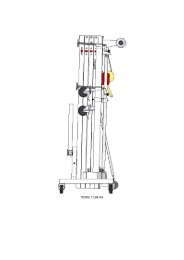
TORRE ELEVADORA<br />
MANUAL DE INSTRUCCIONES<br />
GB<br />
D<br />
ELEVATOR TOWER<br />
OPERATING INSTRUCTIONS<br />
TRAVERSENLIFT<br />
BEDIENUNGSANLEITUNG
fantek<br />
Ferros y Aluminio Navarro S.L.<br />
®<br />
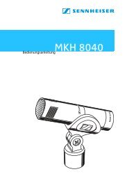
W<br />
U<br />
N1<br />
N2<br />
J<br />
S<br />
R<br />
F<br />
L<br />
H<br />
O<br />
P<br />
V<br />
T<br />
Q
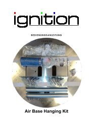
A<br />
B<br />
T-<strong>107</strong>/016
T-<strong>107</strong>/011<br />
T-<strong>107</strong>/006<br />
T-<strong>107</strong>/018<br />
T-<strong>107</strong>/005<br />
T-<strong>107</strong>/007<br />
ACC/13<br />
ACC/21<br />
ACC/18<br />
T-<strong>107</strong>/014<br />
T-<strong>107</strong>/013<br />
T-<strong>107</strong>/012<br />
T-<strong>107</strong>/016<br />
T-<strong>107</strong>/001<br />
T-<strong>107</strong>/009<br />
T-<strong>107</strong>/010<br />
C<br />
T-<strong>107</strong>/015<br />
T-<strong>107</strong>/010<br />
ACC/25<br />
ACC/22<br />
T-<strong>107</strong>/031<br />
ACC/29<br />
®<br />
fantek<br />
Ferros y Aluminio Navarro S.L.
A<br />
T-<strong>107</strong>/017<br />
T-<strong>107</strong>/020<br />
T-<strong>107</strong>/029<br />
T-117/020<br />
B<br />
T-<strong>107</strong>/034<br />
ACC/25<br />
T-<strong>107</strong>/033<br />
T-<strong>107</strong>/002<br />
B1<br />
ACC/25<br />
T-<strong>107</strong>/026<br />
T-<strong>107</strong>/026<br />
T-<strong>107</strong>/003
B1<br />
T-<strong>107</strong>/021<br />
T-<strong>107</strong>/025<br />
T-<strong>107</strong>/004<br />
EN FUNCIONAMIENTO<br />
T-<strong>107</strong>/026<br />
T-<strong>107</strong>/026<br />
T-<strong>107</strong>/027<br />
T-<strong>107</strong>/021<br />
ACC/25<br />
T-<strong>107</strong>/022
T-<strong>107</strong>/019<br />
T-<strong>107</strong>/028<br />
ACC/18<br />
T-<strong>107</strong>/017<br />
ACC/22<br />
T-<strong>107</strong>/004<br />
T-<strong>107</strong>/025<br />
BLOQUEADO
T-<strong>107</strong>/018<br />
T-<strong>107</strong>/017<br />
T-<strong>107</strong>/032<br />
ACC/15-002<br />
ACC/15-004<br />
ACC/15-003<br />
ACC/15<br />
ACC/15-001<br />
ACC/15-004<br />
ACC/15-002<br />
ACC/15-003
ACC/14-001<br />
C<br />
ACC/14<br />
T-<strong>107</strong>/024<br />
ACC/14-002<br />
T-<strong>107</strong>/024<br />
ACC/14-002<br />
ACC/14-003<br />
ACC/14-003
1.- Introducción.<br />
Estimados señores, con el objetivo de optimizar el uso de nuestra torre elevadora T-<strong>107</strong><br />
hemos elaborado este manual. Le rogamos lea atentamente estas instrucciones antes<br />
de utilizar la torre.<br />
Todos nuestros productos han sido sometidos a las más exigentes pruebas y controles<br />
durante el proceso de fabricación.<br />
Para que las certificaciones incorporadas al presente manual surtan efecto se deberán<br />
emplear repuestos originales en todas las reparaciones.<br />
Para cualquier consulta sobre el producto debe indicarse el número de referencia y el<br />
año de construcción o número de serie en su defecto.<br />
2.- Datos técnicos.<br />
Torre elevadora telescópica modelo T-<strong>107</strong>. Esta torre está diseñada para levantar<br />
cargas en sentido vertical a diferentes alturas seleccionables, como soporte para<br />
estructuras y aparatos de iluminación.<br />
2.1.- Carga máxima elevable de 325 Kg.<br />
2.2.- Carga mínima elevable de 25 Kg.<br />
2.3.- Altura máxima: 7 m.<br />
2.4.- Altura mínima: 1,90 m.<br />
- Altura mínima para la carga : 0,20 m.<br />
2.5.- Área de la base: 2,25 x 2 m.<br />
2.6.- Área de la base cerrada: 0,5 x 0,5 m.<br />
2.7.- Peso: 175 Kg.<br />
2.8.- Cabestrante de 900 Kg. de carga máxima con freno automático de retención de<br />
la carga. Homologado en Dusseldorf según DIN 15020 y VBG 8 con el nº GS03015.<br />
2.9.- Cable: Acero según DIN 3060. Calidad 180 Kg./mm 2 resistente a la torsión.<br />
Diámetro del cable 6 mm.<br />
2.10.- Material de construcción: Cuerpo principal en perfil de aluminio extrusionado<br />
6082-T6. Base y patas en perfil de acero según EN 10305.<br />
2.11.- Sistema deslizante sobre rodillos de nilatron de cinco tramos accionados por<br />
cable de acero guiado por poleas acanaladas con cojinetes de rodamiento a bolas.<br />
2.12.- Platillos estabilizadores ajustables en las patas, con apoyos antideslizantes de<br />
caucho.<br />
2.13.- Anclaje de las patas por gatillos de seguridad.<br />
2.14.- Sistema de seguridad interno anti-rotura del cable.<br />
2.15.- Nivel de burbuja para ajustar la posición vertical de la torre.
2.16.- Protección antióxido y acabado anodizado, también en color negro.<br />
2.17.- Dispositivo de conexión de toma a tierra, ACC/29.<br />
2.18.- Ruedas direccionales para el transporte de la torre en posición vertical y<br />
plegada hasta su emplazamiento de trabajo.
3.- Medidas de seguridad.<br />
3.1.- Colocar la torre elevadora sólo en superficies duras y planas.<br />
3.2.- Comprobar que las patas están insertadas a fondo y sujetas por los gatillos<br />
retenedores de seguridad (R).<br />
3.3.- Comprobar que la torre se encuentra en posición vertical mediante el nivel de<br />
burbuja (F) situado en el tramo base. Ajustar, si fuera necesario, con los platillos de<br />
apoyo (Q), girando la manivela (H) en el sentido adecuado, siempre manteniendo las<br />
ruedas de la base en contacto con el suelo como otro punto de apoyo.<br />
3.4.- Si se utiliza al aire libre, colocar la torre en suelo firme y asegurarla contra la fuerza<br />
del viento mediante tirantes de cable de acero. Los tirantes de cable de acero deben<br />
tener un diámetro mínimo de 6 mm.<br />
3.5.- En caso de ser necesario se deberá conectar la torre a tierra a través del<br />
dispositivo de conexión habilitado para ello, ACC/29.<br />
3.6.- No usar escaleras encima de la torre ni apoyarlas en ella.<br />
3.7.- Cuidado con salientes, cables, etc. Por encima de la torre.<br />
3.8.- No ponerse debajo de la carga.<br />
3.9.- No mover la torre si está cargada o elevada.<br />
3.10.- Antes de utilizar la torre, verificar el estado del cable, éste no debe presentar<br />
rotura de hilos o aplastamiento. No usar nunca cables en malas condiciones.<br />
3.11.- No desmontar nunca la manivela del cabestrante (W), ni ningún elemento del<br />
mismo en ningún caso.<br />
3.12.- Se recomienda fijar la manivela del cabrestante una vez se disponga la torre en<br />
posición de trabajo.<br />
3.13.- La carga mínima para el funcionamiento del freno sin problemas es de 25 Kg. Sin<br />
esta carga mínima el freno no actuará.<br />
3.14.- No engrasar ni lubricar el mecanismo de freno del cabestrante.<br />
3.15.- No autorizada para elevador de personas.<br />
3.16.- Para el transporte hay que bajar todos los tramos y asegurar el bloqueo de los<br />
tramos, con el freno (O) correspondiente.
4.- Instrucciones de uso.<br />
4.1.- Colocar la torre elevadora sobre una superficie plana y firme en su<br />
emplazamiento de trabajo.<br />
4.2.- Sacar las patas (P) de su soporte para transporte (S) e insertarlas a fondo en sus<br />
alojamientos de trabajo (V) comprobando que quedan sujetas por los gatillos<br />
retenedores de seguridad. (R). Las patas largas se deben disponer sobre la parte<br />
frontal y las patas cortas sobre la parte trasera.<br />
FIGURA 1<br />
Introducir las Patas<br />
Comprobar los Gatillos de Seguridad<br />
4.3.- Ajustar la posición vertical de la torre mediante los platillos de apoyo regulables<br />
(Q) girando las manivelas (H) en el sentido necesario para lograr que la burbuja del<br />
indicador de nivel (F) quede centrada en el círculo. Hay que tener en cuenta que<br />
cuando se lleve a cabo la nivelación se deberán mantener las ruedas de transporte en<br />
contacto con el suelo como otro punto de apoyo.<br />
FIGURA 2<br />
Regulación de los Platillos
4.4.- Sacar las horquillas de carga (U) quitando los pasadores (L), y colocarlos en<br />
posición para soportar la carga. Colocar los pasadores de seguridad.<br />
FIGURA 3<br />
2<br />
2<br />
1<br />
1<br />
Quitar los pasadores (L)<br />
3<br />
Sacar las horquillas de carga (U)<br />
4<br />
4<br />
3<br />
Posicionar las horquillas en posición<br />
Colocar los pasadores de seguridad<br />
La posición de las horquillas de carga (U) en posición de cargar debe ser tal que la<br />
indicación quede en la parte superior y se de una inclinación como se muestra en la<br />
siguiente imagen.<br />
FIGURA 4<br />
Orientación correcta de la horquillas
4.5.- Colocar la carga a elevar sobre las horquillas de la torre mediante un soporte<br />
adecuado según el caso, de forma que el peso de la carga solo actúe en sentido<br />
vertical. La carga deberá ser como mínimo de 25 Kg. La carga máxima recomendada<br />
nunca deberá estar más desplazada de 25 cm, desde la parte trasera de las horquillas<br />
de carga.<br />
FIGURA 5<br />
25 cm<br />
Carga Máxima<br />
Posición de la carga<br />
4.6.- En los montajes que se utilicen varias torres de carga frontal, T-<strong>107</strong>, T-116 y T-117, se<br />
recomienda el uso de estas torres de forma que en queden encaradas de dos en dos,<br />
compensándose de esta forma las cargas soportadas por ambas torres, e<br />
incrementando así considerablemente la estabilidad del conjunto.<br />
FIGURA 6<br />
Ejemplo de montaje de 2 torres
4.7.- No se recomienda el uso de la torre como soporte individual para cualquier<br />
aplicación. Este tipo de instalaciones puede afectar seriamente a su estabilidad,<br />
especialmente con cargas suspendidas que pueden ser movidas por el viento u otra<br />
fuerza externa, incrementando la necesaria resistencia debido a la aplicación de<br />
fuerzas dinámicas sobre la torre.<br />
FIGURA 7<br />
4.8.- Elevación:<br />
Quitar el freno (O) y elevar la torre girando la manivela del cabestrante (W) en el<br />
sentido de las agujas del reloj (N1), elevando la carga hasta la altura deseada.<br />
FIGURA 8<br />
®<br />
fantek<br />
Ferros y Aluminio Navarro S.L.<br />
1<br />
2<br />
Quitar el freno (O) de los tramos<br />
Giro del cabrestante y elevación del tramo
®<br />
Ferros y Aluminio Navarro S.L.<br />
4.9.- Aguantar:<br />
Soltar la manivela del cabestrante (W), esta se mantendrá en esa posición por la<br />
actuación del freno automático accionado por la carga.<br />
FIGURA 9<br />
fantek<br />
Posición de la torre elevada<br />
La torre puede dejarse en cualquier posición intermedia que se necesite, soltando<br />
simplemente la manivela.<br />
Se recomienda trabar la manivela del cabestrante con una cadena para evitar la<br />
manipulación por personas ajenas.
®<br />
Ferros y Aluminio Navarro S.L.<br />
4.10.- Descenso:<br />
La maniobra de descenso se consigue de la manera contraria. Girar la manivela del<br />
cabestrante (W) en sentido contrario a las agujas del reloj (N2) descendiendo la carga<br />
hasta que vayan bajando los diferentes tramos hasta que la torre quede<br />
completamente plegada a su altura mínima.<br />
FIGURA 10<br />
Giro del cabrestante y descenso del tramo<br />
®<br />
fantek<br />
Ferros y Aluminio Navarro S.L.<br />
fantek<br />
Posición final de la operación de descenso<br />
La torre puede dejarse en cualquier posición intermedia que se necesite del mismo<br />
modo que al subir la carga.<br />
Si durante la operación de ascenso o descenso de la torre ésta queda bloqueada por<br />
el freno de seguridad, elevar la torre hasta su máxima altura para desbloquearla y<br />
continuar con el descenso de forma lenta y continua.
4.11.- Para transportar la torre es necesario plegarla bajando completamente los<br />
tramos. Fijando el carro elevador con el freno (O). Desmontar las patas liberando los<br />
gatillos de retención y colocarlas en su posición de transporte (S). Apretar los tornillos<br />
de sujeción (J).<br />
FIGURA 11<br />
Posición de Transporte<br />
Es muy importante accionar el freno (O) cuando la torre elevadora vaya a ser<br />
transportada para evitar el deslizamiento de los tramos.
5.- Mantenimiento.<br />
5.1.- Comprobar periódicamente el estado del cable. Si un cable presenta rotura de<br />
hilos o aplastamiento, debe ser sustituido inmediatamente por otro nuevo. No utilizar la<br />
torre elevadora con cables en mal estado.<br />
Utilizar solamente cable de acero DIN 3060 resistente a la torsión.<br />
5.2.- La torre elevadora se suministra completamente engrasada de fábrica. No<br />
obstante, se recomienda engrasar periódicamente según el uso, la corona dentada<br />
del cabestrante, los cojinetes del árbol de accionamiento y el buje, la rosca de la<br />
manivela y los tramos.<br />
ATENCIÓN:<br />
No engrasar ni lubricar el mecanismo del freno.<br />
Los discos de freno, han sido engrasados con una grasa especial resistente al calor y la<br />
presión. No deben ser utilizados otros productos, distintos al original suministrado por la<br />
empresa, para evitar influir negativamente en el funcionamiento del freno.<br />
No es necesario engrasar los discos de freno.<br />
5.3.- La torre elevadora T-<strong>107</strong>, debe ser comprobada por un experto como mínimo una<br />
vez al año de acuerdo con su utilización.<br />
5.4.- Solamente deben utilizarse piezas de repuesto originales para garantizar una<br />
continuada seguridad de uso.<br />
El usuario pierde todos los derechos de garantía, si incorpora otros repuestos que no<br />
sean originales o lleva a cabo cualquier modificación del producto.<br />
5.5.- Para solicitar cualquier pieza de repuesto debe de indicarse el número de<br />
referencia y el año de fabricación que figura en las hojas de despiece de este manual.
REF DESCRIPCION MATERIAL ACABADO<br />
T-<strong>107</strong>/001 Base <strong>107</strong> Acero Zincado / Negro<br />
T-<strong>107</strong>/002 Carro Acero Zincado / Negro<br />
T-<strong>107</strong>/003 Carro Aluminio Aluminio Aluminio / Negro<br />
T-<strong>107</strong>/004 Juego péndulo seguridad Aluminio-Latón Aluminio<br />
T-<strong>107</strong>/005 Cable 6mm Acero-Nylon Galvanizado<br />
T-<strong>107</strong>/006 Cabrestante 8 AF Acero Zincado<br />
T-<strong>107</strong>/007 Tirante Acero Galvanizado / Negro<br />
T-<strong>107</strong>/008 Nivel Base Plástico Verde<br />
T-<strong>107</strong>/009 Pata corta Acero Zincado / Negro<br />
T-<strong>107</strong>/010 Pata larga Acero Zincado / Negro<br />
T-<strong>107</strong>/011 Tramo 1 Aluminio Aluminio / Negro<br />
T-<strong>107</strong>/012 Tramo 2 Aluminio Aluminio / Negro<br />
T-<strong>107</strong>/013 Tramo 3 Aluminio Aluminio / Negro<br />
T-<strong>107</strong>/014 Tramo 4 Aluminio Aluminio / Negro<br />
T-<strong>107</strong>/015 Tramo 5 Nylon Aluminio / Negro<br />
T-<strong>107</strong>/016 Rueda Base Goma Negro<br />
T-<strong>107</strong>/017 Polea interior 95 Acero Zincado<br />
T-<strong>107</strong>/018 Portapolea tramo base Acero Zincado / Negro<br />
T-<strong>107</strong>/019 Balón portapolea Zamak Aluminio<br />
T-<strong>107</strong>/020 Pletina sujetacable Acero Zincado / Negro<br />
T-<strong>107</strong>/021 Polea nylon Nylatron Nylatron<br />
T-<strong>107</strong>/022 Juego tornillo polea nylon Acero Zincado<br />
T-<strong>107</strong>/023 Tapon Nylon Nylon Blanco<br />
T-<strong>107</strong>/024 Usillopata Zamak Zamak<br />
T-<strong>107</strong>/025 Cuña + Tornillo Plástico Blanco<br />
T-<strong>107</strong>/026 Tornillo Carro + Tuerca Acero Zincado<br />
T-<strong>107</strong>/027 Pasador 10 + R Acero Zincado<br />
T-<strong>107</strong>/028 Cubrepolea Acero Zincado<br />
T-<strong>107</strong>/029 Juego tornillo M12 + Tuerca Polea Acero Zincado<br />
T-<strong>107</strong>/030 Tornillo Base M10 + Tuerca Acero Zincado<br />
T-<strong>107</strong>/031 Rueda pata Goma Negro<br />
T-<strong>107</strong>/032 Tornillo polea hierro Acero Zincado<br />
T-<strong>107</strong>/033 Sujetacable Acero Zincado<br />
T-<strong>107</strong>/034 Sujetacable superior Acero Zincado<br />
ACC/13 Gatillo seguridad Hexagonal Acero Zincado<br />
ACC/14 Estabilizador completo M20 Acero Zincado<br />
ACC/14-001 Maneta estabilizadora Acero Zincado<br />
ACC/14-002 Perno roscado M20 Acero Zincado<br />
ACC/14-003 Plato estabilizador Acero-Caucho Zincado<br />
ACC/15 Freno <strong>107</strong> Acero Zincado / Negro<br />
ACC/15-001 Cuerpo Freno <strong>107</strong> Acero Zincado / Negro<br />
ACC/15-002 Muelle Freno <strong>107</strong> Acero Zincado / Negro<br />
ACC/15-003 Arandela Freno <strong>107</strong> Acero Zincado / Negro<br />
ACC/15-004 Pasador Freno <strong>107</strong> Acero Zincado / Negro<br />
ACC/18 Portapatas <strong>107</strong> Acero Zincado / Negro<br />
ACC/21 Pomo para portapata Acero-Plástico Zincado / Negro<br />
ACC/22 Plancha Cabrestante <strong>107</strong> Acero Zincado / Negro<br />
ACC/25 Cuernos <strong>107</strong> Acero Zincado<br />
ACC/29 Dispositivo Toma Tierra Grande Acero Zincado
1. Introduction<br />
Dear customer. We have written this manual with the objective to optimize the use of<br />
our lifting tower T <strong>107</strong>. We ask you to read these directions attentively before using the<br />
tower.<br />
All our products have been submitted to the most exigent tests and controls during the<br />
process of fabrication.<br />
For the certifications contained in the present manual to take effect, only original spare<br />
parts must be used in all repair works.<br />
The reference number and the year of construction or the serial number must be<br />
indicated for any consultation on the product.<br />
2. Technical specifications<br />
Lifting telescopic tower model T-<strong>107</strong>. This tower is designed to lift loads such as supports<br />
for structures and illumination gadgetry in a vertical sense to different heights.<br />
2.1.- Max. load: 325 kg<br />
2.2.- Min. load: 25 kg<br />
2.3.- Max. height: 7 m<br />
2.4.- Min. height: 1,90 m<br />
Min. height for the load: 0,20 m<br />
2.5.- Base area: 2,25 x 2 m<br />
2.6.- Folded base area: 0,50 x 0,50 m<br />
2.7.- Weight: 175 kg<br />
2.8.- Winch: 900 kg. Maximum load with automatic stop load brake. Certified in<br />
Düsseldorf according to DIN 15020 and VBG 8 with the number GS03015.<br />
2.9.- Cable: Steel DIN 3060. Tensile strength 180 kg/mm2. Twisting-resistant. 6 mm cable<br />
diametre.<br />
2.10.- Construction material: Principal body aluminium profiles 6082-T6. Base and legs<br />
steel profiles EN 10305.<br />
2.11.- Five-profile sliding system on nilatron rollers operated by steel cable driven by<br />
grooved pulleys with ball-bearing pads.<br />
2.12.- Adjustable stabilizer plates in the legs with nonslip rubber supports.<br />
2.13.- Leg anchorage by safety triggers (R).<br />
2.14.- Internal safety system against cable breakage.<br />
2.15.- Bubble level for vertical alignment of the tower.<br />
2.16.- Antirust protection and electroplated zinc or black finish.
2.17.- Ground connection device, ACC/29.<br />
2.18.- Wheels for transporting the tower in upright or folded position to its working<br />
location.<br />
3. Safety precautions<br />
3.1.- Place the tower only on a solid and flat surface.<br />
3.2.- Check that the legs are fully inserted and secured by the retaining safety triggers<br />
(R).<br />
3.3.- With the bubble level (F) located at the base profile, check that the tower is in<br />
vertical position. If necessary, adjust its alignment with the plates (Q) by turning the<br />
handle (H) in the appropriate sense, always keeping the base wheels in touch with the<br />
ground as another supporting point.<br />
3.4.- When used out in the open, place the tower on hard ground and secure it against<br />
wind force by means of steel cable braces. These steel cable braces must have a<br />
minimum diametre of 6 mm.<br />
3.5.- If necessary, the tower must be anchored to the ground with the appropriate<br />
connecting device ACC/29.<br />
3.6.- Do not use ladders on the tower nor lean them on it.<br />
3.7.- Be careful with any cables, prominent objects etc. placed above the tower.<br />
3.8.- Do not stand under the load.<br />
3.9.- Do not move the tower when it is elevated with a load.<br />
3.10.- Before using the tower, check the state of the cable. This must be free of cuts and<br />
fraying. Never use cables in bad condition.<br />
3.11.- Never dismount the winch handle (W) or any element of the winch under any<br />
circumstances.<br />
3.12.- Once the tower is ready in its working position it is recommended to lock the<br />
winch handle.<br />
3.13.- The minimum load for a safe operation of the brake is 25 kg. The brake will not<br />
function without this minimum load.<br />
3.14.- Do not grease or lubricate the brake mechanism of the winch.<br />
3.15.- Not permitted for use as passenger lift.<br />
3.16.- For transportation it is necessary to retract all profiles and lock them with the<br />
brake (O).
4. Operation<br />
4.1.- Place the tower on a flat and solid surface in its site of operation.<br />
4.2.- Pull the legs out of their support for transport (S) and insert them in their working<br />
lodges (V). Check that they are fully inserted and fastened by the retaining safety<br />
triggers (R). The long legs must be mounted at the front and the short ones at the rear.<br />
SEE FIGURE 1.<br />
4.3.- Adjust the vertical alignment of the tower with the support plates (Q) by turning the<br />
handle (H) in the required sense until the bubble of the level (F) becomes centered in<br />
the circle. When leveling the tower, the transport wheels must have firm contact with<br />
the ground as another supporting point.<br />
SEE FIGURE 2.<br />
4.4.- Extract the loading forks (U) after removing the safety bolts (L) and bring them into<br />
position to support the load. Then put in the safety bolts.<br />
SEE FIGURE 3.<br />
In their loading position, the loading forks (U) must be aligned so that the indication<br />
mark appears on the topside showing a slope as illustrated in the following picture.<br />
SEE FIGURE 4.<br />
4.5.- Place the load to lift on the tower forks by means of a suitable support so that the<br />
load can only move in a vertical sense. The minimum load must be at least 25 kg. The<br />
maximum recommended load must never be placed farther than 25 cm from the first<br />
tower section.<br />
SEE FIGURE 5.<br />
4.6.- In set-ups with several front towers such as the T-<strong>107</strong>, T-116 and T-117 models, it is<br />
recommended to put up these towers facing back to back, thereby balancing the<br />
loads carried by both towers and making the assembly considerably stronger.<br />
SEE FIGURE 6.<br />
4.7.- We don’t recommend to use the tower as individual support for any application.<br />
Such installations can seriously affect the stability of the tower, especially with hanging<br />
loads which can be moved by the wind or any other external force. This requires the<br />
load to have a greater resistance to dynamic forces which may act upon the tower.<br />
SEE FIGURE 7.<br />
4.8.- Up:<br />
Release the brake (O) and lift the tower by turning the winch handle clockwise (N1) to<br />
raise the load to the required height.<br />
SEE FIGURE 8.<br />
4.9.- Hold:<br />
Releasing the winch handle (W) will activate the winch's automatic brake.<br />
SEE FIGURE 9.
The tower may be stopped in any desired intermediate position just by releasing the<br />
handle.<br />
It is recommended to secure the winch handle with a chain to avoid manipulations by<br />
unauthorized people.<br />
4.10.- Down:<br />
Descending the load is done the other way round. Turn the winch handle (W)<br />
counterclockwise (N2) to lower the load and retract the individual profiles until the<br />
tower is completely folded down to its minimal height.<br />
SEE FIGURE 10.<br />
Just like when lifting the load, the tower may be stopped in any desired intermediate<br />
position.<br />
If the tower should become blocked by the emergency brake during the up or down<br />
movement, extend the tower to its maximum height to unlock it and continue the<br />
operation, moving the winch handle in a slow and steady way.<br />
4.11.- For transport it is necessary to fold down the tower completely. Fix the cart with<br />
the brake (O). Dismount the legs by releasing the retention triggers and place them in<br />
their transporting position (S). Press the fixing screws (J).<br />
SEE FIGURE 11.<br />
It is very important to activate the brake (O) when the lifting tower is going to be<br />
transported to avoid slipping of the profiles.<br />
5. Maintenance<br />
5.1.- All cables must be checked regularly. Faulty cables need to be replaced<br />
immediately. Do not use the lifting tower with faulty cables. It is dangerous.<br />
Use only torsion-free steel cables according to DIN 3060 standard.<br />
5.2.- The tower is delivered ex works completely greased. Depending on its mechanical<br />
strain, however, it is recommended to grease the crown wheel of the winch, the pads<br />
and bushings of the drive shaft, the thread of the handle and the profiles of the tower<br />
periodically.<br />
ATTENTION:<br />
Do not apply oil or grease to the brake mechanism.<br />
The brake discs have been pregreased with a special heat and pressure resistant<br />
grease. To avoid malfunctions of the winch brake, no other products must be used<br />
except the original provided by the company.<br />
It is not necessary to grease the brake discs.<br />
5.3.- The lifting tower T-<strong>107</strong> must be inspected at least once a year by a specialized<br />
technician.<br />
5.4.- Only original spare parts must be used to ensure a consistent operational safety.
The user shall lose all warranty claims if he uses any other than original spare parts or<br />
modifies the product in any way.<br />
5.5.- In case a spare part is required, it is necessary to indicate its reference number<br />
which can be found in the spare parts table in this manual.<br />
SEE TABLE 1.
1. Einführung<br />
Sehr geehrter Anwender, dieses Manual wurde mit dem Ziel einer optimalen Nutzung<br />
unseres Hublifts T-<strong>107</strong> verfasst. Wir bitten Sie, vor Benutzung des Lifts diese Anleitung<br />
aufmerksam durchzulesen.<br />
Alle unsere Produkte durchlaufen während des Herstellungsprozesses strenge Tests und<br />
Kontrollen.<br />
Damit die im vorliegenden Manual enthaltenen Bescheinigungen ihre Gültigkeit<br />
behalten, müssen bei allen Reparaturen stets Original-Ersatzteile verwendet werden.<br />
Für jede Produktberatung müssen Referenznummer und Baujahr oder Seriennummer<br />
angegeben werden.<br />
2. Technische Daten<br />
Teleskop-Turmlift Modell T-<strong>107</strong>. Dieser Lift ist dafür ausgelegt, Lasten wie beispielsweise<br />
Traversen und Beleuchtungselemente in senkrechter Richtung auf unterschiedliche<br />
Nutzhöhe anzuheben.<br />
2.1. – Maximallast: 325 kg<br />
2.2. – Mindestlast: 25 kg<br />
2.3. – Max. Höhe: 7 m<br />
2.4. – Min. Höhe: 1,90 m.<br />
Min. Lasthöhe: 0,20 m<br />
2.5. – Stellfläche: 2,25 x 2 m<br />
2.6. – Stellfläche zusammengeklappt: 0,50 x 0,50 m<br />
2.7. – Gewicht: 175 kg<br />
2.8. – Seilwinde: 900 kg Höchstlast mit automatischer Lastbremse. Zertifiziert in Düsseldorf<br />
nach DIN 15020 und VBG 8 mit der Prüfnummer GS03015.<br />
2.9. – Kabel: Stahl DIN 3060. Zugfestigkeit: 180 kg/mm2. Verdrillsicher. 6 mm<br />
Seildurchmesser.<br />
2.10. – Aufbau: Hauptkörper aus Aluprofilen 6082-T6. Basis und Standbeine aus<br />
Stahlprofilen EN 10305.<br />
2.11. – Teleskopsystem mit fünf Profilen auf Nilatron-Rollen. Antrieb über Stahlseil in<br />
kugelgelagerten Führungsscheiben.<br />
2.12. – Justierbare Stabilisierungsplatten in den Standbeinen mit rutschsicheren<br />
Gummifüßen.<br />
2.13. – Verankerung der Beine über Sicherungstrigger (R).<br />
2.14. – Internes Sicherungssystem gegen Seilbruch.<br />
2.15. – Wasserwaage zur vertikalen Ausrichtung.
2.16. – Rostschutzfinish in Zink oder schwarz eloxiert.<br />
2.17. – Bodensicherung ACC/29.<br />
2.18. – Räder zum Transport des Lifts in senkrechter Position sowie in eingefahrenem<br />
Zustand zum Einsatzort.<br />
3. Sicherheitshinweise<br />
3.1. – Den Lift nur auf stabilen, ebenen Flächen aufstellen.<br />
3.2. – Vergewissern Sie sich, dass die Beine voll eingeschoben und mit den<br />
Sicherungstriggern (R) gesichert sind.<br />
3.3. – Mit Hilfe der im Basisprofil eingelassenen Wasserwaage (F) prüfen, ob der Lift<br />
absolut senkrecht steht. Gegebenenfalls mit den Platten (Q) ausgleichen, hierzu die<br />
Kurbel (H) in der entsprechenden Richtung drehen; dabei müssen die Räder der<br />
Grundplatte als zusätzliche Stützpunkte ständigen Bodenkontakt haben.<br />
3.4. – Bei Benutzung im Freien den Lift auf festen Boden stellen und durch Spannstreben<br />
mit Stahlseilen von mindestens 6 mm Durchmesser gegen Scherwinde sichern.<br />
3.5. – Falls notwendig, den Lift mit dem hierfür vorgesehenen Verbindungselement<br />
ACC/29 am Boden verankern.<br />
3.6. – Auf dem Lift keine Leitern verwenden und auch nicht daran anlehnen.<br />
3.7. – Auf über dem Lift hängende Kabel, vorstehende Teile usw. achten.<br />
3.8. – Nicht unter der Last stehenbleiben.<br />
3.9. – Den Lift nicht mit angehobener Last bewegen.<br />
3.10. – Vor Benutzung des Lifts den Zustand des Kabels prüfen. Dieses darf keine spröden<br />
Adern aufweisen oder ausgefranst sein. Kabel in schlechtem Zustand dürfen keinesfalls<br />
verwendet werden!<br />
3.11. – Unter keinen Umständen die Windenkurbel (W) oder irgendein Bauteil der Winde<br />
abschrauben.<br />
3.12. – Es wird empfohlen, die Windenkurbel zu arretieren, sobald der Lift in seiner<br />
Arbeitsposition steht.<br />
3.13. – Die Mindestlast für einen problemlosen Betrieb der Bremse beträgt 25 kg. Ohne<br />
diese Mindestlast funktioniert die Bremse nicht korrekt.<br />
3.14. – Den Bremsmechanismus der Winde weder schmieren noch ölen.<br />
3.15. – Nicht als Personenlift zugelassen.<br />
3.16. – Zum Transport müssen alle Profile heruntergefahren und mit der Bremse (O)<br />
blockiert werden.
4. Betrieb<br />
4.1. – Den Lift an seinem Einsatzort auf einer stabilen, ebenen Fläche aufstellen.<br />
4.2. – Die Beine aus ihrer Transporthalterung (S) herausziehen und in ihre Arbeitsposition<br />
(V) einführen; darauf achten, dass sie ganz eingeschoben und mit den<br />
Sicherungstriggern (R) arretiert sind. Die langen Ausleger müssen nach vorn zeigen, die<br />
kurzen nach hinten.<br />
SIEHE ABBILDUNG 1<br />
4.3. – Die vertikale Position des Lifts mit Hilfe der Stützplatten (Q) ausrichten. Die Kurbel<br />
(H) solange in die erforderliche Richtung drehen, bis sich die Luftblase der<br />
Wasserwaage mittig im Kreis befindet. Beim Ausrichten müssen die Transportrollen als<br />
zusätzliche Stützpunkte ständigen Bodenkontakt haben.<br />
SIEHE ABBILDUNG 2<br />
4.4. – Nach Entfernen der Sicherungsbolzen (L) die Lastträger (U) ausziehen und in<br />
Position zur Lastaufnahme bringen. Die Sicherungsbolzen wieder einstecken.<br />
SIEHE ABBILDUNG 3<br />
Die Lastträger (U) müssen so zur Last hin ausgerichtet werden, dass die Markierung auf<br />
der Oberseite sichtbar ist und eine Schräge aufweist, wie in der folgenden Abbildung<br />
gezeigt ist.<br />
SIEHE ABBILDUNG 4<br />
4.5. – Die anzuhebende Last mittels einer geeigneten Haltevorrichtung so auf den<br />
Lastträgern des Lifts platzieren, dass sie sich nur in vertikaler Richtung bewegen kann.<br />
Das Lastgewicht muss mindestens 25 kg betragen und die Last darf sich nie weiter als 25<br />
cm vom hinteren Ende der Lastträger befinden.<br />
SIEHE ABBILDUNG 5<br />
4.6.- Bei Einsatz mehrerer Frontlifte wie etwa der Modelle T-<strong>107</strong>, T-116 und T-117 wird<br />
empfohlen, diese Tower mit den Rückseiten zueinander aufzustellen, da hierdurch die<br />
von beiden Liften getragenen Lasten besser ausbalanciert sind und der gesamte<br />
Aufbau wesentlich stabiler wird.<br />
SIEHE ABBILDUNG 6<br />
4.7.- Wir raten davon ab, den Tower als Einzellastträger zu verwenden. Solche<br />
Installationen können die Stabilität des Towers erheblich beeinträchtigen, vor allem bei<br />
Hängelasten, die vom Wind oder durch irgendwelche anderen Kräfte bewegt werden<br />
können. Hierzu müsste die Last unempfindlicher sein gegen die dynamische Kräfte,<br />
welche auf den Tower einwirken können.<br />
SIEHE ABBILDUNG 7<br />
4.8. – Anheben<br />
Die Bremse (O) lösen und den Lift durch Drehen der Windenkurbel (W) im Uhrzeigersinn<br />
(N1) hochfahren, bis die Last die benötigte Höhe erreicht hat.<br />
SIEHE ABBILDUNG 8
4.9. – Fixieren<br />
Nach Loslassen des Kurbelgriffs (W) wird dieser durch die automatische Windenbremse<br />
arretiert.<br />
SIEHE ABBILDUNG 9<br />
Der Lift kann in jeder beliebigen Zwischenhöhe angehalten werden – einfach die Kurbel<br />
loslassen.<br />
Es wird empfohlen, die Windenkurbel mit einer Kette gegen Manipulationen durch<br />
unbefugte Personen zu sichern.<br />
4.10. – Absenken<br />
Das Herablassen der Last erfolgt in der umgekehrten Reihenfolge. Den Kurbelgriff (W)<br />
gegen den Uhrzeigersinn (N2) drehen, damit sich die einzelnen Profile ineinander<br />
schieben, bis der Lift wieder auf seine minimale Höhe eingefahren ist.<br />
SIEHE ABBILDUNG 10<br />
Der Lift kann wie beim Hochfahren in jeder benötigten Zwischenhöhe angehalten<br />
werden.<br />
Sollte der Lift während des Hebe- oder Absenkvorgangs durch die Notbremse<br />
blockieren, den Lift auf maximale Höhe ausfahren, um die Bremse zu lösen. Danach<br />
den Vorgang unter langsamem und gleichmäßigem Drehen der Windenkurbel<br />
fortsetzen.<br />
4.11. – Zum Transport des Lifts müssen die Profile vollständig zusammengeschoben<br />
werden. Den Rollwagen mit der Bremse (O) fixieren. Die Beine nach Abziehen der<br />
Sicherungstrigger abnehmen und in ihre Transportposition (S) bringen. Die<br />
Fixierschrauben (J) eindrücken.<br />
SIEHE ABBILDUNG 11<br />
Vor dem Transport des Lifts unbedingt die Bremse (O) aktivieren, damit die Profile nicht<br />
herausgleiten können.<br />
5. Wartung<br />
5.1. – Alle Seile müssen regelmäßig überprüft und defekte Seile sofort ersetzt werden.<br />
Achtung: Den Hublift nicht mit defekten Seilen betreiben!<br />
Nur verdrillsichere Stahlseile gemäß DIN 3060 verwenden.<br />
5.2. – Der Lift wird ab Werk vollständig geschmiert ausgeliefert. Je nach Beanspruchung<br />
ist es allerdings ratsam, das Antriebskegelrad der Winde, Druckflächen und Laufbuchse<br />
der Antriebsachse, das Kurbelgriffgewinde sowie die Liftprofile gelegentlich<br />
nachzuschmieren.<br />
ACHTUNG:<br />
Den Bremsmechanismus nicht ölen oder schmieren.<br />
Die Bremsscheiben wurden mit wärme- und druckresistentem Spezialfett vorgeschmiert.<br />
Um die Funktion der Windenbremse nicht zu beeinträchtigen, dürfen keine anderen als<br />
die von der Firma gelieferten Originalteile verwendet werden.
Die Bremsscheiben brauchen nicht geschmiert zu werden.<br />
5.3. – Der Hublift T-<strong>107</strong> muss mindestens einmal pro Jahr durch einen fachkundigen<br />
Techniker überprüft werden.<br />
5.4. – Um eine dauerhafte Betriebssicherheit zu gewährleisten, dürfen nur Original-<br />
Ersatzteile verwendet werden.<br />
Der Betreiber verliert sämtliche Garantieansprüche, sobald er andere als Original-<br />
Ersatzteile einbaut oder irgendwelche Veränderungen an dem Produkt vornimmt.<br />
5.5. – Wird irgendein Ersatzteil benötigt, muss dessen Referenznummer laut den in dieser<br />
Anleitung enthaltenen Ersatzteilabbildungen angegeben werden.<br />
SIEHE TABELLE 1.
®<br />
fantek<br />
Ferros y Aluminio Navarro S.L.<br />
DECLARACION CE DE CONFORMIDAD<br />
D. JOSE LUIS NAVARRO NAVARRO en calidad de Administrador de la empresa FERROS<br />
Y ALUMINIO NAVARRO S.L., fabricante de FABRICANTE DE ESTRUCTURAS Y ELEMENTOS<br />
DE ELEVACIÓN PARA EL SECTOR DEL ESPECTÁCULO con domicilio social en Polígono<br />
Industrial El Boni, Camí del Port nº 3, Catarroja, Valencia, declara bajo su única<br />
responsabilidad que la máquina,<br />
MARCA: Torre T-<strong>107</strong><br />
DESCRIPCIÓN: Torre telescópica de elevación de carga.<br />
MODELO: T-<strong>107</strong><br />
AÑO DE CONSTRUCCIÓN:<br />
PESO: 175 Kg<br />
CARGA MÁXIMA ADMISIBLE: 325 kg<br />
se halla en conformidad con la Directiva de Máquinas 98/37/CE.<br />
que en su diseño y fabricación han sido tenidos en cuenta tanto en su totalidad como<br />
parcialmente, los aspectos recogidos en las normas armonizadas siguientes:<br />
UNE EN ISO 12100 – 1:2004 “Seguridad de las máquinas. Conceptos básicos, principios<br />
generales para el diseño. Parte 1: Terminología básica, metodología”<br />
UNE EN ISO 12100 – 2:2004 “Seguridad de las máquinas. Conceptos básicos. Principios<br />
generales para el diseño. Parte 2: Principios y especificaciones técnicas”<br />
cumpliendo también las normas nacionales alemanas:<br />
BGV C1 (GUV/VC1) / BGG 912 (GUV-G912) con certificado de ensayo 083/2005.<br />
habiendo constituido el correspondiente expediente técnico de construcción;<br />
y para que conste a los efectos oportunos emite la presente declaración de<br />
conformidad.<br />
En Catarroja a 7 de Julio de 2006<br />
Firmado:<br />
José Luis Navarro Navarro<br />
Administrador
EC DECLARATION OF CONFORMITY<br />
®<br />
fantek<br />
Ferros y Aluminio Navarro S.L.<br />
Mr. JOSE LUIS NAVARRO NAVARRO as the General Manager of the company FERROS Y<br />
ALUMINIO NAVARRO S.L., MANUFACTURER OF STRUCTURES AND ELEVATION TOWERS FOR<br />
THE SPECTACLES INDUSTRY whose address is Polígono Industrial El Boni, Camí del Port nº<br />
3, Catarroja, Valencia, Spain, declares in his own responsibility that the machine<br />
MARK: Tower T-<strong>107</strong><br />
DESCRIPTION:<br />
Telescopic tower for elevating loads<br />
MODEL: T-<strong>107</strong><br />
YEAR OF CONSTRUCTION:<br />
WEIGHT:<br />
175 kg<br />
ADMISSIBLE PEAK LOAD: 325 kg<br />
complies with the following requirements in their standard design:<br />
Machinery Directive 98/37/EEC<br />
and that in its design and fabrication, the following harmonized norms were taken into<br />
account:<br />
EN ISO 12100 – 1:2004 “Safety of machinery. Basic concepts, general principles for<br />
design. Part 1: Basic terminology, methodology”<br />
EN ISO 12100 – 2:2004 “Safety of machinery. Basic concepts, general principles for<br />
design. Part 2: Technical principles”<br />
The above-mentioned machine has been tested in accordance with the following<br />
German standards:<br />
BGV C1 (GUV/VC1) / BGG 912 (GUV-G912) with test certificate 083/2005 by:<br />
IBB Ingenieure<br />
Nollendorfstrasse 18<br />
45472 Mülheim an der Ruhr<br />
GS test certificate No. 083/2005.<br />
Catarroja, July 07, 2006<br />
Signed:<br />
José Luis Navarro Navarro<br />
General Manager
EU-KONFORMITÄTSERKLÄRUNG<br />
®<br />
fantek<br />
Ferros y Aluminio Navarro S.L.<br />
Als Generaldirektor der Firma FERROS Y ALUMINIO NAVARRO S.L., HERSTELLER VON<br />
APPARATUREN UND HUBLIFTEN FÜR DIE VERANSTALTUNGSINDUSTRIE mit Firmensitz<br />
Polígono Industrial El Boni, Camí del Port No. 3, Catarroja, Valencia, Spanien, erklärt Herr<br />
JOSE LUIS NAVARRO in eigener Verantwortung, dass das nachfolgende Gerät<br />
TYP: Tower T-<strong>107</strong><br />
BESCHREIBUNG:<br />
Teleskop-Hublift für Lasthebungen<br />
MODElL: T-<strong>107</strong><br />
BAUJAHR:<br />
GEWICHT:<br />
175 kg<br />
ZULÄSSIGE HÖCHSTLAST: 320 kg<br />
in seiner serienmäßigen Ausführung den folgenden Anforderungen entspricht:<br />
Maschinenrichtlinie 98/37/EEC<br />
und dass bei seiner Konzeption und Herstellung die folgenden harmonisierten Normen<br />
berücksichtigt wurden:<br />
EN ISO 12100 – 1:2004 ’Sicherheit von Maschinen - Grundbegriffe, allgemeine<br />
Gestaltungsleitsätze - Teil 1 : Grundsätzliche Terminologie, Methodologie.’<br />
EN ISO 12100 – 2:2004 ’Sicherheit von Maschinen - Grundbegriffe, allgemeine<br />
Gestaltungsleitsätze - Teil 2 : Technische Leitsätze.’<br />
Das oben genannte Gerät wurde in Übereinstimmung mit deutschen Normen geprüft.<br />
BGV C1 (GUV/VC1) / BGG 912 (GUV-G912) mit Prüfzertifikat 083/2005 durch:<br />
IBB Ingenieure<br />
Nollendorfstraße 18<br />
45472 Mülheim a. d. Ruhr<br />
GS-Prüfzertifikat Nr. 083/2005.<br />
Catarroja, 07. Juli 2006<br />
Unterzeichnet:<br />
José Luis Navarro Navarro<br />
Generaldirektor
Número de serie: Serial number : Laufende Nummer:<br />
Primer test en fábrica. First test in factory. Erstprüfung im Werk.<br />
Fecha/Date/Datum<br />
Testado por/Tested by/Prüfer<br />
Examen a los cuatro<br />
años.<br />
Four years test. UVV Prüfung (alle 4<br />
Jahre)<br />
Fecha/Date/Datum<br />
Testado por/Tested by/Prüfer<br />
Notas/Notes/ Anmerkung<br />
Firma/Signature/ Unterschrift<br />
Examen anual a partir<br />
del cuarto año.<br />
Fecha/Date/Datum:<br />
Annual test after the fourth<br />
year.<br />
Testado por/Tested by/Prüfer:<br />
UVV Jährlicher Test<br />
nach dem vierten Jahr.<br />
Notas/Notes/ Anmerkung:<br />
Firma/Signature/ Unterschrift:
Fecha/Date/Datum:<br />
Testado por/Tested by/Prüfer:<br />
Notas/Notes/ Anmerkung:<br />
Firma/Signature/ Unterschrift:<br />
Fecha/Date/Datum:<br />
Testado por/Tested by/Prüfer:<br />
Notas/Notes/ Anmerkung:<br />
Firma/Signature/ Unterschrift:<br />
Fecha/Date/Datum:<br />
Testado por/Tested by/Prüfer:<br />
Notas/Notes/ Anmerkung:<br />
Firma/Signature/ Unterschrift:<br />
Fecha/Date/Datum:<br />
Testado por/Tested by/Prüfer:<br />
Notas/Notes/ Anmerkung:<br />
Firma/Signature/ Unterschrift:
Todos los tests mencionados<br />
solo son obligatorios en<br />
aquellos países con<br />
regulación específica en la<br />
materia, aplicada mediante<br />
regulaciones o leyes. Como<br />
fabricantes, sumamente<br />
recomendamos pasar todos<br />
los tests con el objetivo de<br />
prevenir cualquier daño y<br />
mantener perfectamente<br />
nuestras torres elevadoras.<br />
All the tests mentioned are<br />
only mandatory in those<br />
countries with specific<br />
regulations in this respect,<br />
applicable by domestic rules<br />
or laws. As a manufacturer,<br />
we highly recommend to pass<br />
all the tests to prevent any<br />
damage and to ensure a<br />
perfect operation of our lifting<br />
towers.<br />
Alle genannten Tests sind nur<br />
in den Ländern<br />
vorgeschrieben,<br />
wo<br />
diesbezüglich spezielle<br />
Regelungen gelten, die durch<br />
inländische Vorschriften oder<br />
Gesetze Anwendung finden.<br />
Als Hersteller raten wir<br />
dringend zur Durchführung<br />
aller Tests, um jeglichen<br />
Schaden zu verhindern und<br />
einen einwandfreien Betrieb<br />
unserer Hublifte zu<br />
gewährleisten.
Camí del Port, 3 • Pol. Ind. El Boni<br />
46470 • Catarroja (Valencia), Spain<br />
Tel.: +34 96 126 01 68 • Fax: +34 96 126 64 56<br />
www.fantek.net • e-mail: info@fantek.net