instrucciones de instalación, funcionamiento y ... - Hitecsa
instrucciones de instalación, funcionamiento y ... - Hitecsa
instrucciones de instalación, funcionamiento y ... - Hitecsa

You also want an ePaper? Increase the reach of your titles
YUMPU automatically turns print PDFs into web optimized ePapers that Google loves.
MANDO POR CABLE MPCE / WIRED CONTROLLER MPCE / COMMANDE CÂBLÉE MPCE<br />
MANUAL DE USUARIO / USER'S MANUAL / MANUEL DE L'UTILISATEUR<br />
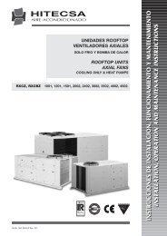
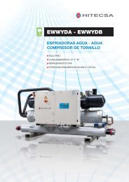
UNIDADES ENFRIADORAS DE AGUA<br />
VENTILADORES AXIALES<br />
COMPRESORES DE TORNILLO<br />
SOLO FRIO<br />
LIQUID CHILLING UNITS<br />
AXIAL FANS<br />
SCREW COMPRESSOR<br />
COOLING ONLY<br />
GROUPES D'EAU GLACÉE<br />
VENTILATEURS AXIAUX<br />
COMPRESSEUR A VIS<br />
FROID SEUL<br />
EWYD 370.2, 400.2, 470.2, 530.2, 580.2, 670.2, 740.2,<br />
800.2, 870.2, 910.2, 950.2, 1010.2, 1080.2,<br />
1120.2, 1200.3, 1270.3, 1370.3, 1460.3, 1530.3<br />
INSTRUCCIONES DE INSTALACIÓN, FUNCIONAMIENTO Y MANTENIMIENTO<br />
INSTALLATION, OPERATION AND MAINTENANCE INSTRUCTIONS<br />
INSTRUCTIONS POUR L'INSTALLATION, FONCTIONNEMENT ET ENTRETIEN<br />
11.07 Ref. 200925 Rev. 100<br />
1
INDICE<br />
INFORMACION GENERAL..........................................................4-9<br />
CARACTERISTICAS TECNICAS................................................10-16<br />
DIMESIONES.........................................................................17-26<br />
RECEPCION DE LA UNIDAD...................................................27-30<br />
CONEXIONES HIDRAULICAS..................................................31-33<br />
PUESTA EN MARCHA.............................................................34,35<br />
CONEXIONES ELECTRICAS....................................................36-43<br />
CONTROL.............................................................................44-53<br />
MANTENIMIENTO..................................................................54-60
INFORMACION GENERAL<br />
PLACA DE CARACTERÍSTICAS<br />
Las unida<strong>de</strong>s se i<strong>de</strong>ntifican gracias a la placa <strong>de</strong> características<br />
que se muestra junto a este texto.<br />
La placa muestra el tipo <strong>de</strong> equipo (serie y mo<strong>de</strong>lo), el número <strong>de</strong><br />
serie, el año <strong>de</strong> fabricación, el número <strong>de</strong> esquema eléctrico, los<br />
principales datos técnicos y el logotipo y la dirección <strong>de</strong>l fabricante.<br />
La placa se aplica sobre la unidad, generalmente cerca <strong>de</strong>l cuadro<br />
eléctrico o en la parte exterior <strong>de</strong> los paneles.<br />
NO SE DEBE QUITAR NUNCA.<br />
NÚMERO DE SERIE<br />
I<strong>de</strong>ntifica <strong>de</strong> forma única la máquina, permite conocer las<br />
características específicas <strong>de</strong> la unidad e i<strong>de</strong>ntificar los<br />
componentes instalados en ella.<br />
Sin este número, no es posible i<strong>de</strong>ntificar con certeza los<br />
repuestos específicos <strong>de</strong> la unidad.<br />
En caso <strong>de</strong> solicitud <strong>de</strong> intervención, proporcionar siempre el tipo<br />
<strong>de</strong> máquina y el número <strong>de</strong> serie.<br />
Anotarlos en el espacio que se da más abajo para tenerlos al<br />
alcance <strong>de</strong> la mano en caso <strong>de</strong> necesidad.<br />
Tipo <strong>de</strong> unidad: _________________________________<br />
Nº serie: _________________________________<br />
Esquema eléctrico: __________________________<br />
Año <strong>de</strong> fabricación: ___________________________<br />
4<br />
11.07 Ref. 200925 Rev.100
INFORMACION GENERAL<br />
Este manual ha sido redactado para permitir una correcta instalación, puesta a punto y mantenimiento <strong>de</strong> la unidad.<br />
INSTRUCCIÓNES DEL MANUAL<br />
lo tanto es fundamental leer las siguientes <strong>instrucciones</strong> prestando la <strong>de</strong>bida atención.<br />
El fabricante <strong>de</strong>clina cualquier responsabilidad, por eventuales daños a las personas o a las cosas, como consecuencia <strong>de</strong><br />
una incorrecta utilización <strong>de</strong> la unidad y/o por la inobservancia <strong>de</strong> las presentes <strong>instrucciones</strong>.<br />
CONSERVACIÓN DEL MANUAL<br />
Este manual y el esquema eléctrico <strong>de</strong> la unidad <strong>de</strong>ben conservarse atentamente y permanecer a disposición <strong>de</strong>l operador<br />
para cualquier consulta posterior.<br />
PERSONAL CUALIFICADO<br />
Instalar la unidad, someterla a ensayo con la asistencia <strong>de</strong>l personal cualificado (ley n. 46 <strong>de</strong>l 5/3/1990) en posesión <strong>de</strong> los<br />
requisitos <strong>de</strong> la ley.<br />
NORMAS DE SEGURIDAD LOCALES<br />
Respetar las normas <strong>de</strong> seguridad locales en vigor durante la instalación.<br />
RED ELÉCTRICA<br />
Comprobar que las características <strong>de</strong> la red eléctrica sean conformes a los datos indicados en la placa <strong>de</strong> fábrica <strong>de</strong> la unidad<br />
situada en la parte interna <strong>de</strong>l cuadro eléctrico general.<br />
EMBALAJE<br />
El material <strong>de</strong> embalaje (bolsas <strong>de</strong> plástico, poliestireno celular, clavos, etc.) constituye una fuente potencial <strong>de</strong> peligro por lo<br />
que <strong>de</strong>be mantenerse fuera <strong>de</strong>l alcance <strong>de</strong> los niños y reciclarse correctamente según las normas <strong>de</strong> seguridad locales en<br />
vigor.<br />
MANTENIMIENTO<br />
Antes <strong>de</strong> efectuar cualquier operación <strong>de</strong> mantenimiento corte la alimentación eléctrica <strong>de</strong> la unidad. Las operaciones tienen<br />
que efectuarse ateniéndose a las normativas <strong>de</strong> seguridad locales.<br />
INSPECCIONES PERIÓDICAS<br />
Efectúe inspecciones periódicas para <strong>de</strong>tectar posibles piezas dañadas o rotas. Si no se reparan podrían ocasionar daños a<br />
personas o cosas.<br />
FALTA – MALFUNCIONAMIENTO<br />
En caso <strong>de</strong> averías o anomalías <strong>de</strong> <strong>funcionamiento</strong>, apagar la unidad.<br />
REPARACIONES<br />
Las reparaciones <strong>de</strong>ben realizarse, siempre y exclusivamente, en centros <strong>de</strong> asistencia técnica autorizados por el fabricante,<br />
utilizando sólo repuestos originales. El no respeto <strong>de</strong> dichas advertencias podría perjudicar las características <strong>de</strong> seguridad <strong>de</strong><br />
la unidad.<br />
MODIFICACIÓNES<br />
Se <strong>de</strong>clina toda responsabilidad <strong>de</strong>l fabricante con vencimiento <strong>de</strong> la garantía en caso <strong>de</strong> modificaciones eléctricas y/o<br />
mecánicas. Las alteraciones en general no autorizadas expresamente y que no respeten lo que se indica en este manual<br />
provocan el vencimiento <strong>de</strong> la garantía.<br />
UTILIZACIÓN<br />
La unidad tendrá que <strong>de</strong>stinarse exclusivamente al uso para el que se ha concebido:<br />
La unidad está <strong>de</strong>stinada al enfriamiento <strong>de</strong> agua o agua con glicol para el acondicionamiento, con los límites<br />
previstos por el boletín técnico y por este manual.<br />
Cualquier otro uso distinto al especificado no implica para el fabricante ningún compromiso o vínculo <strong>de</strong> ningún tipo.<br />
PRINCIPIOS DE LA SEGURIDAD EN LA INSTALACION<br />
La unidad está diseñada y construida, <strong>de</strong> modo tal, que no supone un riesgo para la salud y la seguridad <strong>de</strong> las personas. De<br />
tal forma se han adoptado soluciones <strong>de</strong> proyecto a<strong>de</strong>cuadas para eliminar las posibles causas <strong>de</strong> riesgo en la instalación. En<br />
caso <strong>de</strong> que no hubiera sido posible intervenir en fase <strong>de</strong> proyecto para prevenir y/o eliminar el riesgo, tomar como referencia<br />
las normas <strong>de</strong> conducta ilustradas en la sección "Riesgos residuales”<br />
ACTUALIZACIÓN DE LOS DATOS<br />
Las continuas mejoras aportadas al producto pue<strong>de</strong>n <strong>de</strong>terminar variaciones <strong>de</strong> los datos indicados incluso sin preaviso por<br />
parte <strong>de</strong>l fabricante.<br />
11.07 Ref. 200925 Rev.100 5
INFORMACION GENERAL<br />
NORMATIVAS Y CERTIFICACIONES<br />
CERTIFICACIÓN UNI EN ISO 9001<br />
HITECSA, buscando siempre la satisfacción <strong>de</strong> sus clientes ha obtenido el Sistema <strong>de</strong> Calidad ISO 9001 referida a su propia<br />
actividad productiva. Esta voluntad, se manifiesta en un empeño continuo para mejorar la calidad y fiabilidad <strong>de</strong> todos nuestros<br />
productos; la actividad comercial, el diseño, las materias primas, la producción y el servicio post venta, son el medio que nos<br />
permite cumplir nuestros objetivos.<br />
MARCA CE<br />
Los productos HITECSA poseen la marca CE en conformidad a lo previsto por la directiva comunitaria correspondiente, y sus<br />
últimas modificaciones, así como con la legislación nacional correspondiente a cada país:<br />
- 98/37/CE<br />
- 89/336/CEE modificada con las directrices 92/31/CEE y 93/68/CEE<br />
- 73/23/CEE modificada con la directiva 93/68/CEE<br />
- 97/23/CE<br />
CERTIFICACIÓN<br />
EUROVENT<br />
HITECSA participa al programa <strong>de</strong> Certificación EUROVENT "Enfriadoras <strong>de</strong> Agua". Los productos interesados se encuentran<br />
en la guía EUROVENT <strong>de</strong> los productos certificados y en el sito www.eurovent-certification.com.<br />
6<br />
11.07 Ref. 200925 Rev.100
INFORMACION GENERAL<br />
GENERALIDADES<br />
En esta sección se señalan las situaciones más comunes<br />
que, no pudiendo ser controladas por el fabricante, podrían<br />
originar situaciones <strong>de</strong> peligro para personas o cosas.<br />
ZONA PELIGROSA<br />
La figura inferior muestra el área en la que pue<strong>de</strong> actuar<br />
únicamente un operador autorizado.<br />
• Zona peligrosa externa se i<strong>de</strong>ntifica por una<br />
superficie <strong>de</strong>terminada alre<strong>de</strong>dor <strong>de</strong> la máquina y <strong>de</strong><br />
la proyección en el suelo <strong>de</strong> la misma en la vertical<br />
con la máquina suspendida.<br />
• Zona peligrosa interna es el área a la que se pue<strong>de</strong><br />
acce<strong>de</strong>r solamente mediante la remoción <strong>de</strong>liberada<br />
<strong>de</strong> los carenados o <strong>de</strong> algunas partes <strong>de</strong> éstos.<br />
D<br />
A = 2000 mm<br />
C = 2000 mm<br />
A<br />
C<br />
B<br />
B = 2000 mm<br />
D = 2000 mm<br />
TRASLADO<br />
Las operaciones <strong>de</strong> transporte efectuadas sin la necesaria<br />
precaución y pru<strong>de</strong>ncia pue<strong>de</strong>n ser causa <strong>de</strong> caída o<br />
vuelco <strong>de</strong> la unidad y pue<strong>de</strong>n producir daños <strong>de</strong> extrema<br />
gravedad para cosas, personas e incluso a la misma<br />
unidad.<br />
Transportar la unidad respetando las advertencias<br />
indicadas en el embalaje, en el presente manual y la<br />
normativa local vigente.<br />
En caso <strong>de</strong> fugas <strong>de</strong> gas refrigerante ver sección “Ficha <strong>de</strong><br />
seguridad”.<br />
INSTALACIÓN<br />
Una errónea instalación <strong>de</strong> la unidad pue<strong>de</strong> originar<br />
perdidas <strong>de</strong> agua, acumulación <strong>de</strong> con<strong>de</strong>nsa, fugas <strong>de</strong><br />
refrigerante, electrocuciones, incendios, mal<br />
<strong>funcionamiento</strong> o daños en la unidad.<br />
Verificar que la instalación sea realizada única y<br />
exclusivamente por servicio técnico autorizado y que<br />
respete las <strong>instrucciones</strong> <strong>de</strong>l manual y la normativa local<br />
vigente.<br />
Instalar la unidad en lugar don<strong>de</strong> puedan haber<br />
esporádicas fugas <strong>de</strong> gas inflamable y la acumulación <strong>de</strong><br />
dichos gases alre<strong>de</strong>dor <strong>de</strong> la unidad pue<strong>de</strong> ser causa <strong>de</strong><br />
explosiones e incendios. Verificar con suma atención el<br />
lugar don<strong>de</strong> irá instalada la unidad.<br />
Instalar la unidad en lugar no adapto a resistir el peso y/o<br />
que no garantice una a<strong>de</strong>cuada fijación pue<strong>de</strong> ocasionar la<br />
caída o vuelco <strong>de</strong> la unidad, produciendo posibles daños a<br />
cosas, personas o a la misma unidad.<br />
Verificar con suma atención el preciso lugar don<strong>de</strong> irá<br />
instalada la unidad y sus fijaciones.<br />
Un fácil acceso para niños, personas no autorizadas o<br />
animales a la unidad pue<strong>de</strong> ser origen <strong>de</strong> acci<strong>de</strong>ntes e<br />
infortunios, algunos <strong>de</strong> ellos graves. La unidad <strong>de</strong>be ser<br />
instalada en lugares accesibles solo por personal<br />
autorizado y/o prever protecciones para evitar<br />
intromisiones en la zona peligrosa.<br />
RIESGOS GENÉRICOS<br />
Olor a quemado, humo, u otros señales <strong>de</strong> anomalías<br />
graves pue<strong>de</strong>n indicar el inicio <strong>de</strong> situaciones que podrían<br />
causar daños a cosas, personas o a la propia unidad.<br />
Seccionar la unidad eléctricamente (seccionador amarillorojo).<br />
Para indicar y resolver el problema que <strong>de</strong> origen a dicha<br />
anomalía, contactar servicio técnico autorizado.<br />
Un contacto acci<strong>de</strong>ntal con baterías <strong>de</strong> intercambio,<br />
compresores, tuberías <strong>de</strong> envío u otros componentes<br />
pue<strong>de</strong>n originar lesiones y/o quemaduras.<br />
Siempre hay que hacer uso <strong>de</strong> los a<strong>de</strong>cuados indumentos<br />
a<strong>de</strong>más <strong>de</strong> guantes <strong>de</strong> protección para efectuar cualquier<br />
operación al interior <strong>de</strong> la zona peligrosa.<br />
Las operaciones <strong>de</strong> mantenimiento y <strong>de</strong> reparación<br />
efectuadas por personal no cualificado pue<strong>de</strong>n originar<br />
daños a cosas, personas e incluso a la propia unidad.<br />
Siempre hay que contactar servicio <strong>de</strong> asistencia técnica<br />
cualificado.<br />
El no cerrar los paneles <strong>de</strong> la unidad, y no verificar que<br />
hayan sido atornillados correctamente todos los tornillos <strong>de</strong><br />
los paneles pue<strong>de</strong> originar daños a cosas, personas e<br />
incluso a la propia unidad.<br />
Es necesario verificar periódicamente que todos los<br />
paneles estén correctamente montados y bloqueados.<br />
En caso <strong>de</strong> incendio, la temperatura <strong>de</strong>l refrigerante pue<strong>de</strong><br />
alcanzar valores tales que hacen que la presión supere el<br />
valor <strong>de</strong> seguridad permitido, provocando la fuga <strong>de</strong>l<br />
refrigerante o explosiones <strong>de</strong> las partes <strong>de</strong>l circuito que<br />
permanecen aisladas por el cierre <strong>de</strong> las llaves.<br />
Nunca pararse <strong>de</strong>lante <strong>de</strong> las válvulas <strong>de</strong> seguridad y<br />
nunca <strong>de</strong>jar cerradas las llaves <strong>de</strong>l circuito frigorífico.<br />
PARTE ELÉCTRICA<br />
Una línea <strong>de</strong> conexión con la red eléctrica no completa y/o<br />
con cables incorrectamente dimensionados, y/o con<br />
dispositivos <strong>de</strong> protección ina<strong>de</strong>cuados pue<strong>de</strong>n causar<br />
shock por <strong>de</strong>scarga eléctrica, intoxicación, daños a la<br />
unidad o incendio.<br />
Realizar todas las operaciones en la instalación eléctrica<br />
tomando como referencia el esquema eléctrico a<strong>de</strong>más <strong>de</strong>l<br />
presente manual para asegurar una buena instalación.<br />
Una incorrecta fijación <strong>de</strong> la cobertura <strong>de</strong> los componentes<br />
eléctricos facilita la entrada <strong>de</strong> polvo, agua, etc. al interior,<br />
originando posibles <strong>de</strong>scargas eléctricas, daños a la<br />
unidad o incendio. Siempre hay que fijar bien la cobertura a<br />
la unidad.<br />
Las partes metálicas <strong>de</strong> la unidad, cuando están bajo<br />
tensión y no están conectadas correctamente a la<br />
instalación <strong>de</strong> tierra, pue<strong>de</strong>n provocar shock por <strong>de</strong>scargas<br />
eléctricas o muerte por fulminación. Prestar extrema<br />
atención al efectuar la conexión con la instalación <strong>de</strong> tierra.<br />
Cualquier contacto con partes en tensión accesibles en el<br />
interior, una vez quitados los paneles, pue<strong>de</strong> causar shock<br />
por <strong>de</strong>scarga eléctrica, quemaduras o incluso muerte por<br />
fulminación.<br />
11.07 Ref. 200925 Rev.100 7
INFORMACION GENERAL<br />
Abrir y bloquear con llave el seleccionador general antes<br />
<strong>de</strong> quitar los paneles, y señalar que se está trabajando<br />
mediante cartel <strong>de</strong> peligro.<br />
Cualquier contacto con partes que podrían entrar en<br />
tensión como consecuencia <strong>de</strong> la puesta en marcha <strong>de</strong> la<br />
unidad pue<strong>de</strong> producir shock por <strong>de</strong>scarga eléctrica,<br />
quemaduras e incluso muerte por fulminación.<br />
Cuando no es necesario mantener los circuitos en tensión,<br />
se recomienda abrir el seleccionador situado en la línea <strong>de</strong><br />
alimentación <strong>de</strong> la unidad, bloquear con llave y dotarlo <strong>de</strong><br />
cartel <strong>de</strong> peligro.<br />
PARTES EN MOVIMIENTO<br />
Cualquier contacto con las transmisiones o con la<br />
aspiración <strong>de</strong> los ventiladores pue<strong>de</strong> originar lesiones.<br />
Antes <strong>de</strong> acce<strong>de</strong>r al interior <strong>de</strong> la unidad, hay que abrir el<br />
seleccionador situado en la línea <strong>de</strong> alimentación <strong>de</strong> la<br />
unidad, bloquear el seleccionador con llave y advertir <strong>de</strong>l<br />
riesgo con el especifico cartel <strong>de</strong> peligro.<br />
Cualquier contacto con los ventiladores pue<strong>de</strong> originar<br />
lesiones.<br />
Antes <strong>de</strong> elevar las rejillas <strong>de</strong> protección o los ventiladores,<br />
hay que abrir el seleccionador situado en la línea <strong>de</strong><br />
alimentación <strong>de</strong> la unidad, bloquear el seleccionador con<br />
llave y advertir <strong>de</strong>l riesgo con el especifico cartel <strong>de</strong> peligro.<br />
REFRIGERANTES<br />
Cuando intervienen las válvulas <strong>de</strong> seguridad, y la sucesiva<br />
expulsión <strong>de</strong> gas refrigerante, se pue<strong>de</strong>n provocar lesiones<br />
e intoxicaciones. Siempre hay que utilizar los a<strong>de</strong>cuados<br />
indumentos y gafas <strong>de</strong> protección para todas las<br />
operaciones que sean realizadas en el interior <strong>de</strong> la zona<br />
peligrosa.<br />
En caso <strong>de</strong> fugas <strong>de</strong> gas refrigerante ver “Ficha <strong>de</strong><br />
seguridad” <strong>de</strong>l refrigerante.<br />
Cualquier contacto entre llamas libres o fuentes <strong>de</strong> calor<br />
con el refrigerante, o la calefacción <strong>de</strong>l circuito gas en<br />
presión (por ejemplo durante operaciones <strong>de</strong> soldadura)<br />
pue<strong>de</strong> causar explosiones o incendios. Nunca situar<br />
fuentes <strong>de</strong> calor al interior <strong>de</strong> la zona peligrosa.<br />
Las intervenciones <strong>de</strong> manutención o reparación que<br />
necesiten <strong>de</strong> soldadura tiene que realizarse con la<br />
instalación <strong>de</strong>scargada <strong>de</strong>l gas.<br />
PARTE HIDRÁULICA<br />
Defectos en las tuberías, en las conexiones o en las<br />
válvulas <strong>de</strong> cierre pue<strong>de</strong>n producir pérdidas o fugas <strong>de</strong><br />
agua que pue<strong>de</strong>n causar daños a cosas o cortocircuitos en<br />
la unidad.<br />
Hay que realizar todas las conexiones hidráulicas con la<br />
máxima atención, siguiendo las <strong>instrucciones</strong> <strong>de</strong>l presente<br />
manual.<br />
01<br />
02<br />
03<br />
04<br />
05<br />
06<br />
07<br />
Elementos <strong>de</strong><br />
i<strong>de</strong>ntificación <strong>de</strong> la<br />
sustancia<br />
Composición:<br />
informaciones sobre<br />
componentes<br />
I<strong>de</strong>ntificación <strong>de</strong>l riesgo<br />
Medidas <strong>de</strong> primeros<br />
auxilios<br />
Medidas anti-incendio<br />
Medidas en caso <strong>de</strong><br />
escape acci<strong>de</strong>ntal<br />
Manipulación y<br />
almacenamiento<br />
FICHAS DE SEGURIDAD DEL REFRIGERANTE<br />
R-134a<br />
Normas <strong>de</strong>l producto: 134a<br />
N°SDS 00941<br />
Proveedor: ELF ATOCHEM ITALIA<br />
Via Degli Artigianelli 10, 20159 Milano tel. 02/668111<br />
Naturaleza química <strong>de</strong>l preparado Tetrafluoretano<br />
Nombre genérico: Hidrocarburo Alogenado<br />
CAS: 811-97-2<br />
EINECS: 212-377-0<br />
Mayores peligros:<br />
Efectos para la salud: Prácticamente no nocivo<br />
Peligros físicos y químicos: Inflamable al contacto con el aire, en ciertas condiciones <strong>de</strong> temperatura y presión.<br />
Inhalación: Transportar a la víctima al aire abierto. Recurrir al oxígeno o a la respiración artificial si es necesario.<br />
Contacto con la piel: El congelamiento <strong>de</strong>be ser curado como una quemadura térmica.<br />
Contacto con los ojos: Lavado inmediato y abundante con agua. Si persiste la irritación, consulte un oftalmólogo.<br />
Instrucciones para el médico: No suministrar catecolaminas (por la sensibilización causada por el producto).<br />
Peligros específicos:<br />
Con temperaturas elevadas: Descomposición térmica en productos tóxicos y corrosivos. Ácido fluorhídrico. Óxidos <strong>de</strong> carbono<br />
Métodos específicos <strong>de</strong> intervención: Enfriar los contenedores/cisternas con chorros <strong>de</strong> agua. Prohibir cualquier fuente <strong>de</strong> chispas y <strong>de</strong><br />
ignición.<br />
No FUMAR.<br />
Sistemas <strong>de</strong> protección especial para equipos <strong>de</strong> salvamento: Llevar un autorespirador e indumentaria <strong>de</strong> protección<br />
Precauciones individuales: Evitar el contacto con la piel, los ojos y la inhalación <strong>de</strong> los vapores.<br />
En un local cerrado: ventilar o usar un respirador (riesgo <strong>de</strong> asfixia).<br />
PROHIBIDO FUMAR<br />
Alejar cualquier fuente <strong>de</strong> ignición.<br />
Manipulación:<br />
Medidas/precauciones técnicas<br />
Disposiciones <strong>de</strong> almacenamiento aplicables a los productos: GASES PRESURIZADOS<br />
Prever una ventilación y una evacuación apropiada al nivel <strong>de</strong> los aparatos.<br />
Consejos para el uso: Prohibir los puntos <strong>de</strong> ignición y el contacto con las superficies calientes. NO FUMAR<br />
Almacenamiento:<br />
Medidas técnicas/Modalidad <strong>de</strong> almacenamiento: almacenar a temperatura ambiente en el contenedor original. Tener lejos <strong>de</strong> llamas<br />
libres, superficies calientes y fuentes <strong>de</strong> ignición. Conservar en lugar fresco y bien aireado. Proteger los contenedores llenos <strong>de</strong> las fuentes<br />
<strong>de</strong> calor para evitar sobrepresiones.<br />
Recomendados: Acero ordinario, Acero inoxidable.<br />
A evitar: Aleación que contenga más <strong>de</strong>i 2% <strong>de</strong> magnesio<br />
Materias plásticas<br />
8 11.07 Ref. 200925 Rev.100
INFORMACION GENERAL<br />
08<br />
09<br />
10<br />
11<br />
Control <strong>de</strong> la<br />
exposición/protección<br />
individual<br />
Propieda<strong>de</strong>s físicas y<br />
químicas<br />
Estabilidad y<br />
Reactividad<br />
Informaciones<br />
toxicológicas<br />
Medidas <strong>de</strong> precaución a adoptar: Asegurar un recambio <strong>de</strong> aire suficiente y/o una extracción en los ambientes <strong>de</strong> trabajo.<br />
Parámetros <strong>de</strong> control:<br />
Valores límites <strong>de</strong> exposición: Valor límite recomendado por ELF ATOCHEM: VME = 1000ppm=4420mg/m 3<br />
Equipamiento <strong>de</strong> protección individual:<br />
Protección Respiratoria: En caso <strong>de</strong> ventilación insuficiente, llevar un equipamiento <strong>de</strong> respiración a<strong>de</strong>cuado.<br />
Protección <strong>de</strong> las manos: Guantes<br />
Protección <strong>de</strong> los ojos: Gafas <strong>de</strong> protección<br />
Medidas <strong>de</strong> higiene específicas: Evitar el contacto con la piel, los ojos y la inhalación <strong>de</strong> vapores.<br />
Prohibido fumar.<br />
Estado físico (20°C): Gaseoso<br />
Color: Incoloro<br />
Olor: Ligeramente parecido al éter.<br />
pH: No aplicable<br />
Punto/intervalo <strong>de</strong> ebullición: -26,4°C<br />
Temperatura/intervalo <strong>de</strong> fusión: -101°C<br />
Punto <strong>de</strong> inflamabilidad: No se inflama en las condiciones <strong>de</strong> prueba<br />
Temperatura <strong>de</strong> autocombustión: 743°C (1bar) 215°C (3bar)<br />
Presión <strong>de</strong> vapor: (25°C):0.665MPa (6.65bar) a (50°C):1.32MPa (13.2bar) a (70°C): 2.12MPa (21.2bar)<br />
Densidad <strong>de</strong> vapor (25°C): 4.26kg/m 3<br />
Densidad: (25°C): 1206kg/m 3 a (50°C): 1102kg/m 3 a (70°C): 996kg/m 3<br />
Solubilidad:<br />
Agua: (25°C): 0,9g/l<br />
Coeficiente <strong>de</strong> repartición: log Pow = 1.06 (n-otanol/agua)<br />
Otros datos:<br />
Constante <strong>de</strong> Henry: 1.53Pa m 3 /mol<br />
No disociado en agua<br />
Solubilidad <strong>de</strong>l agua en el producto a 25°C: 0,097% en peso<br />
Temperatura crítica: Tc=101°C<br />
Presión crítica. Pc=4.07MPa (40.7bar)<br />
Condiciones a evitar: Mantener alejado <strong>de</strong> fuentes <strong>de</strong> calor y otras posibles fuentes <strong>de</strong> incendio. Evitar el contacto con llamas y superficies<br />
metálicas incan<strong>de</strong>scentes<br />
Productos <strong>de</strong> <strong>de</strong>scomposición peligrosos a altas temperaturas: Descomposición térmica en productos tóxicos y corrosivos.<br />
Ácido fluorhídrico, óxido <strong>de</strong> carbono (CO)<br />
Otras informaciones: Producto estable a temperatura ambiente.<br />
El producto al contacto con el aire pue<strong>de</strong> formar una mezcla inflamable, en ciertas condiciones <strong>de</strong> temperatura y presión.<br />
Toxicidad aguda:<br />
Inhalación: Experimentado en animales:<br />
Práticamente no nocivo por inhalación.<br />
CL50/inhalación/4 horas/en cobaya>500000ppm<br />
Como para los otros componentes alogenizados volátiles, el producto pue<strong>de</strong> causar, con la acumulación <strong>de</strong> vapores y/o con la inhalación <strong>de</strong><br />
cantida<strong>de</strong>s importantes: pérdida <strong>de</strong> conciencia y problemas cardíacos agravados por el estrés y por la falta <strong>de</strong> oxígeno: riesgo mortal.<br />
Efectos locales:<br />
Contacto con la piel: Congelamiento posible por salpicaduras <strong>de</strong> gas licuado.<br />
Experimentado en animales:<br />
Poco o nada irritante para la piel.<br />
Contacto con los ojos: Experimentado en animales:<br />
Poco o nada irritante para los ojos.<br />
Sensibilización:<br />
Contacto con la piel: Experimentado en animales:<br />
Sin sensibilización cutánea (cobaya).<br />
Toxicidad crónica: Algunos estudios acerca <strong>de</strong> inhalación prolongada en animales no han evi<strong>de</strong>nciado ningún efecto tóxico crónico.<br />
Efectos específicos:<br />
Genotoxicidad:<br />
Según datos experimentales disponibles: no genotóxico<br />
Cancerogénesis:<br />
La experimentación con animales no ha puesto en evi<strong>de</strong>ncia ningún efecto cancerígeno claramente <strong>de</strong>mostrable.<br />
Toxicidad para la reproducción:<br />
Desarrollo fetal: ausencia <strong>de</strong> efectos tóxicos para el <strong>de</strong>sarrollo <strong>de</strong>l feto.<br />
Fertilidad:<br />
Según datos disponibles en animales: Ausencia <strong>de</strong> efectos tóxicos en la fertilidad.<br />
Este documento se refiere al producto en sí, <strong>de</strong> acuerdo a la información proporcionada por ELF ATOCHEM.<br />
En caso <strong>de</strong> combinaciones o mezclas, asegurarse <strong>de</strong> que no impliquen nuevos peligros. Las informaciones <strong>de</strong> esta ficha se dan <strong>de</strong> buena fe y se basan en<br />
nuestros últimos conocimientos acerca <strong>de</strong>l producto en cuestión en fecha <strong>de</strong> la edición <strong>de</strong> la misma. Se llama la atención <strong>de</strong> los usuarios sobre los eventuales<br />
riesgos que se pue<strong>de</strong>n correr cuando el producto venga utilizado para usos diferentes a los cuales está <strong>de</strong>stinado. Esta ficha <strong>de</strong>be ser utilizada y reproducida con<br />
fines <strong>de</strong> prevención y seguridad. La lista <strong>de</strong> los textos legislativos, reglamentarios o administrativos no <strong>de</strong>be ser consi<strong>de</strong>rada agotada. Es un <strong>de</strong>ber <strong>de</strong>l usuario <strong>de</strong>l<br />
producto referirse al conjunto <strong>de</strong> textos oficiales relativos al uso, la conservación y la manipulación <strong>de</strong>l producto <strong>de</strong> los cuales él es el único responsable. El<br />
usuario <strong>de</strong>l producto <strong>de</strong>be dar a conocer a las personas que pue<strong>de</strong>n entrar en contacto con el producto, toda la información necesaria relativa a la seguridad en el<br />
trabajo y a la protección <strong>de</strong> la salud y <strong>de</strong>l ambiente, transmitiéndoles esta ficha <strong>de</strong> datos <strong>de</strong> seguridad.<br />
11.07 Ref. 200925 Rev.100 9
CARACTERISTICAS TECNICAS<br />
Configuración sonora: Estándar (SD) / Insonorización <strong>de</strong> los compresores (IC)<br />
MODELOS 370.2 400.2 470.2 530.2 580.2 670.2 740.2 800.2 870.2 910.2 950.2 1010.2 1080.2 1120.2<br />
REFRIGERACIÓN<br />
Potencia frigorífica 1 kW 365 406 474 527 584 675 736 801 869 915 954 1015 1085 1116<br />
Poten. ass. Compresores kW 111 125 145 163 183 202 221 246 256 272 282 307 340 357<br />
Potencia absorbida total 2 kW 125 139 163 181 200 223 242 267 278 293 305 332 365 382<br />
EER Nr 2.92 2.92 2.92 2.91 2.92 3.03 3.04 3 3.13 3.12 3.13 3.06 2.97 2.92<br />
ESEER Nr 4.03 4.02 4.03 4.01 4.03 4.18 4.19 4.13 4.32 4.31 4.32 4.22 4.11 4.02<br />
COMPRESOR<br />
Tipo compresor 3 DSW<br />
N° compresores Nr 2<br />
Etapas <strong>de</strong> capacidad<br />
Estándar<br />
Nr<br />
stepless/6<br />
Circuito refrigerante Nr 2<br />
INTERCAMBIADOR INTERIOR<br />
Tipo evaporador interior 4 S&T<br />
N° intercambiadores<br />
interiores<br />
Nr 1<br />
Caudal <strong>de</strong> agua l/s 17.4 19.4 22.7 25.2 27.9 32.2 35.2 38.3 41.5 43.7 45.6 48.5 51.8 53.3<br />
Pérdida <strong>de</strong> carga kPa 43 31 41 35 50 27 41 38 56 61 66 74 43 45<br />
INTERCAMBIADOR EXTERIOR<br />
Superficie <strong>de</strong>lantera m 2 19 19 24 24 29.4 29.4 29.4 29.4 35 35 35 35 35 35<br />
VENTILADOR ZONA EXTERNA<br />
Tipo ventilador 5 AX<br />
Número ventiladores Nr 8 8 10 10 10 12 12 12 12 12 13 14 14 14<br />
Entrada aire estándar l/s 44914 44914 52083 56179 59670 68099 68099 68099 79186 79186 84900 87508 87508 87508<br />
CONEXIONES<br />
Conexiones agua 5" 6" / 8 6" / 8" 6" / 8" 6" / 8" 8"<br />
ALIMENTACIÓN<br />
Alimentación estándar V 400/3/50<br />
PESO DE LA UNIDAD ESTÁNDAR<br />
Peso <strong>de</strong>l envío SD kg 4240 4256 5073 5550 5850 6145 6810 7313 7980 8400 8560 8620 8810 8830<br />
Peso en <strong>funcionamiento</strong> SD kg 4402 4418 5257 5772 6072 6397 7105 7696 8442 8862 8983 9043 9216 9236<br />
Peso <strong>de</strong>l envío IC kg 4655 4671 5573 6050 6265 6560 7225 7728 8390 8620 8780 9040 9030 9250<br />
Peso en <strong>funcionamiento</strong> IC kg 4817 4833 5757 6272 6487 6812 7520 8111 8852 9082 9203 9463 9436 9656<br />
(1) Datos referidos a la siguiente condición :<br />
agua intercambiador interior = 12/7 °C<br />
temperatura aire exterior 35°C<br />
(2) La Potencia Absorbida Total, según las indicaciones EUROVENT, no tiene<br />
en cuenta la<br />
parte relativa a las bombas y necesaria para vencer las pérdidas <strong>de</strong> carga<br />
para la circulación <strong>de</strong> la solución en el interior <strong>de</strong> los intercambiadores.<br />
(3) DSW = compresor <strong>de</strong> doble-tornillo<br />
(4) S&T = Multitubular<br />
(5) AX = ventilador axial<br />
LÍMITE DE FUNCIONAMIENTO<br />
MODELOS 370.2 400.2 470.2 530.2 580.2 670.2 740.2 800.2 870.2 910.2 950.2 1010.2 1080.2 1120.2<br />
INTERCAMBIADOR EXTERIOR<br />
Máx.temperatura aire entrada 1 C 47.5 46.5 47 45 45.5 45 44.5 44.5 44 46 45 44.5 43.5 43.5<br />
Máx.temperatura aire entrada 2 °C 52 51 52 50 50 50 49 49 49 51 50 49 48 48<br />
Mín.temperatura aire entrada 3 °C -10 -10 -10 -10 -10 -10 -10 -10 -10 -10 -10 -10 -10 -10<br />
Mín.temperatura aire entrada 4 °C -8 -9 -7 -9 -9 -9 -9 -9 -9 -9 -9 -9 -9 -9<br />
Mín.temperatura aire entrada 5 °C 1 1 7 3 5 3 3 1 2 2 -1 -2 -2 -5<br />
Mín.temperatura aire entrada 6 °C 12 13 17 14 15 13 14 13 14 14 12 12 11 9<br />
INTERCAMBIADOR INTERIOR<br />
Máx.temperatura agua entrada 7 °C 21<br />
Mín.temperatura agua a la salida 8 °C 5<br />
Mín.temperatura agua a la salida 9 °C -8<br />
Nota : la unidad no <strong>de</strong>be ser expuesta, ni alimentada, ni puesta en cualquier<br />
otra situación <strong>de</strong> transporte o estocage, a temperaturas inferiores a -10ºC<br />
Bajo petición è posibile prever contramedidas para el <strong>funcionamiento</strong><br />
también en condiciones ambientales más rígidas. Para peticiones<br />
particulares por favor contactar nuestro Departamento Comercial.<br />
Atención la condición <strong>de</strong> aire en calma esta <strong>de</strong>finida como ausencia<br />
absoluta <strong>de</strong> caudal <strong>de</strong> aire a través <strong>de</strong> la unidad. Débiles vientos pue<strong>de</strong><br />
inducir caudales <strong>de</strong> aire a través <strong>de</strong>l intercambiador <strong>de</strong> aire tales que<br />
provoquen una reducción <strong>de</strong>l limite <strong>de</strong> <strong>funcionamiento</strong> (ver limites con aire a<br />
0,5 m/s y 1 m/s). para evitar esto es necesario emplear barreras<br />
contravientos.<br />
Los valores <strong>de</strong> temperatura mínima <strong>de</strong>l aire en entrada se refieren a<br />
unida<strong>de</strong>s con dispositivo para bajas temperaturas o con ventiladores<br />
ECOFAN. Para la unidad estándar a plena carga y con aire sin movimiento<br />
se pue<strong>de</strong> asumir el valor <strong>de</strong> +18°C.<br />
(1) unidad a plena carga<br />
acqua scambiatore interno = 12/7°C<br />
(2) unidad parcializada (parcialización automática)<br />
(3) unidad a plena carga<br />
aire en el intercambiador exterior en calma<br />
(4) unidad parcializada (parcialización automática)<br />
aire en el intercambiador exterior en calma<br />
(5) unidad parcializada (parcialización automática)<br />
Aire en el intercambiador externo = 0.5m/s<br />
(6) unidad parcializada (parcialización automática)<br />
Aire en el intercambiador externo = 1m/s<br />
(7) Aire en el intercambiador externo 35°C<br />
(8) Versión estandar<br />
Aire en el intercambiador externo 35°C<br />
(9) Versión baja temperatura<br />
Aire en el intercambiador externo 35°C<br />
Fluido tratado con glicol etilénico al 40%<br />
10<br />
11.07 Ref. 200925 Rev.100
CARACTERISTICAS TECNICAS<br />
Configuración sonora: Estándar (SD) / Insonorización <strong>de</strong> los compresores (IC)<br />
MODELOS 1200.3 1270.3 1370.3 1460.3 1530.3<br />
REFRIGERACIÓN<br />
Potencia frigorífica 1 kW 1196 1268 1367 1456 1525<br />
Poten. ass. Compresores kW 375.3 392.9 414.8 431.1 468.7<br />
Potencia absorbida total 2 kW 406.9 427.9 449.8 469.5 507.1<br />
EER Nr 2.94 2.96 3.04 3.1 3.01<br />
ESEER Nr 4.09 4.12 4.22 4.31 4.18<br />
COMPRESOR<br />
Tipo compresor 3 DSW<br />
N° compresores Nr 3<br />
Etapas <strong>de</strong> capacidad Estándar Nr stepless/9<br />
Circuito refrigerante Nr 3<br />
INTERCAMBIADOR INTERIOR<br />
Tipo evaporador interior 4 S&T<br />
N° intercambiadores interiores Nr 1<br />
Caudal <strong>de</strong> agua l/s 57.1 60.6 65.3 69.6 72.8<br />
Pérdida <strong>de</strong> carga kPa 55 69 79 89 97<br />
VENTILADOR ZONA EXTERNA<br />
Tipo ventilador 5 AX<br />
Número ventiladores Nr 18 20 20 22 22<br />
CONEXIONES<br />
Conexiones agua 8"<br />
ALIMENTACIÓN<br />
Alimentación estándar V 400/3/50<br />
PESO DE LA UNIDAD ESTÁNDAR<br />
Peso <strong>de</strong>l envío SD kg 11136 12242 13235 13987 14087<br />
Peso en <strong>funcionamiento</strong> SD kg 10730 11767 12752 13422 13522<br />
Peso <strong>de</strong>l envío IC kg 11806 12907 13905 14657 14757<br />
Peso en <strong>funcionamiento</strong> IC kg 11400 12432 13422 14092 14192<br />
(1) Datos referidos a la siguiente condición :<br />
agua intercambiador interior = 12/7 °C<br />
temperatura aire exterior 35°C<br />
(2) La Potencia Absorbida Total, según las indicaciones EUROVENT, no tiene<br />
en cuenta la<br />
parte relativa a las bombas y necesaria para vencer las pérdidas <strong>de</strong> carga<br />
para la circulación <strong>de</strong> la solución en el interior <strong>de</strong> los intercambiadores.<br />
(3) DSW = compresor <strong>de</strong> doble-tornillo<br />
(4) S&T = Multitubular<br />
(5) AX = ventilador axial<br />
LÍMITE DE FUNCIONAMIENTO<br />
MODELOS 1200.3 1270.3 1370.3 1460.3 1530.3<br />
INTERCAMBIADOR EXTERIOR<br />
Máx.temperatura aire entrada 1 °C 43 43 43 44 43<br />
Máx.temperatura aire entrada 2 °C 49 49 49 50 49<br />
Mín.temperatura aire entrada 3 °C -10 -10 -10 -10 -10<br />
Mín.temperatura aire entrada 4 °C -9 -9 -9 -8 -9<br />
Mín.temperatura aire entrada 5 °C 1 1 1 2 1<br />
Mín.temperatura aire entrada 6 °C 13 13 13 14 13<br />
INTERCAMBIADOR INTERIOR<br />
Máx.temperatura agua entrada 7 °C 21<br />
Mín.temperatura agua a la salida 8 °C 5<br />
Mín.temperatura agua a la salida 9 °C -8<br />
Nota : la unidad no <strong>de</strong>be ser expuesta, ni alimentada, ni puesta en cualquier<br />
otra situación <strong>de</strong> transporte o estocage, a temperaturas inferiores a -10ºC<br />
Bajo petición è posibile prever contramedidas para el <strong>funcionamiento</strong><br />
también en condiciones ambientales más rígidas. Para peticiones<br />
particulares por favor contactar nuestro Departamento Comercial.<br />
Atención la condición <strong>de</strong> aire en calma esta <strong>de</strong>finida como ausencia<br />
absoluta <strong>de</strong> caudal <strong>de</strong> aire a través <strong>de</strong> la unidad. Débiles vientos pue<strong>de</strong><br />
inducir caudales <strong>de</strong> aire a través <strong>de</strong>l intercambiador <strong>de</strong> aire tales que<br />
provoquen una reducción <strong>de</strong>l limite <strong>de</strong> <strong>funcionamiento</strong> (ver limites con aire a<br />
0,5 m/s y 1 m/s). para evitar esto es necesario emplear barreras<br />
contravientos.<br />
Los valores <strong>de</strong> temperatura mínima <strong>de</strong>l aire en entrada se refieren a<br />
unida<strong>de</strong>s con dispositivo para bajas temperaturas o con ventiladores<br />
ECOFAN. Para la unidad estándar a plena carga y con aire sin movimiento<br />
se pue<strong>de</strong> asumir el valor <strong>de</strong> +18°C.<br />
(1) unidad a plena carga<br />
(2) unidad parcializada (parcialización automática)<br />
(3) unidad a plena carga<br />
aire en el intercambiador exterior en calma<br />
(4) unidad parcializada (parcialización automática)<br />
aire en el intercambiador exterior en calma<br />
(5) unidad parcializada (parcialización automática)<br />
Aire en el intercambiador externo = 0.5m/s<br />
(6) unidad parcializada (parcialización automática)<br />
Aire en el intercambiador externo = 1m/s<br />
(7) Aire en el intercambiador externo 35°C<br />
(8) Versión estandar<br />
Aire en el intercambiador externo 35°C<br />
(9) Versión baja temperatura<br />
Aire en el intercambiador externo 35°C<br />
Fluido tratado con glicol etilénico al 40%<br />
11.07 Ref. 200925 Rev.100 11
CARACTERISTICAS TECNICAS<br />
Configuración sonora: Insonorizada (SI)<br />
MODELOS 370.2 400.2 470.2 530.2 580.2 670.2 740.2 800.2 870.2 910.2 950.2 1010.2 1080.2 1120.2<br />
REFRIGERACIÓN<br />
Potencia frigorífica 1 kW 363 399 469 526 576 670 738 802 857 896 939 1018 1102 1137<br />
Poten. ass. Compresores kW 114 127 149 168 184 207 225 247 261 275 281 311 336 349<br />
Potencia absorbida total 2 kW 124 137 161 181 197 222 240 262 277 293 304 336 361 374<br />
EER Nr 2.92 2.91 2.92 2.91 2.92 3.01 3.07 3.06 3.09 3.06 3.09 3.03 3.05 3.04<br />
ESEER Nr 4.18 4.18 4.18 4.18 4.17 4.31 4.38 4.37 4.42 4.38 4.43 4.33 4.36 4.36<br />
COMPRESOR<br />
Tipo compresor 3 DSW<br />
N° compresores Nr 2<br />
Etapas <strong>de</strong> capacidad<br />
Estándar<br />
Nr<br />
stepless/6<br />
Circuito refrigerante Nr 2<br />
INTERCAMBIADOR INTERIOR<br />
Tipo evaporador interior 4 S&T<br />
N° intercambiadores<br />
interiores<br />
Nr 1<br />
Caudal <strong>de</strong> agua l/s 17.3 19.1 22.4 25.1 27.5 32 35.3 38.3 40.9 42.8 44.9 48.6 52.7 54.3<br />
Pérdida <strong>de</strong> carga kPa 43 30 40 35 49 27 41 38 54 59 64 75 44 47<br />
INTERCAMBIADOR EXTERIOR<br />
Superficie <strong>de</strong>lantera m 2 19 19 24 24 29.4 29.4 35 35 35 35 43 48 48 48<br />
VENTILADOR ZONA EXTERNA<br />
Tipo ventilador 5 AX<br />
Número ventiladores Nr 8 8 9 10 10 12 12 12 13 14 18 20 20 20<br />
Entrada aire estándar l/s 33264 33264 38688 41604 44377 49938 59950 59950 62648 65347 74868 83208 83208 83208<br />
CONEXIONES<br />
Conexiones agua 5" 6" / 8" 6" / 8" 6" / 8" 6" / 8" 8"<br />
ALIMENTACIÓN<br />
Alimentación estándar V 400/3/50<br />
PESO DE LA UNIDAD ESTÁNDAR<br />
Peso <strong>de</strong>l envío kg 4835 4851 5683 6270 6525 6820 7820 8413 8700 8800 10254 10654 11064 11304<br />
Peso en <strong>funcionamiento</strong> kg 4997 5013 5867 6492 6747 7072 8115 8796 9162 9262 10677 11077 11470 11710<br />
(1) Datos referidos a la siguiente condición :<br />
agua intercambiador interior = 12/7 °C<br />
temperatura aire exterior 35°C<br />
(2) La Potencia Absorbida Total, según las indicaciones EUROVENT, no tiene<br />
en cuenta la<br />
parte relativa a las bombas y necesaria para vencer las pérdidas <strong>de</strong> carga<br />
para la circulación <strong>de</strong> la solución en el interior <strong>de</strong> los intercambiadores.<br />
(3) DSW = compresor <strong>de</strong> doble-tornillo<br />
(4) S&T = Multitubular<br />
(5) AX = ventilador axial<br />
LÍMITE DE FUNCIONAMIENTO<br />
MODELOS 370.2 400.2 470.2 530.2 580.2 670.2 740.2 800.2 870.2 910.2 950.2 1010.2 1080.2 1120.2<br />
INTERCAMBIADOR EXTERIOR<br />
Máx.temperatura aire entrada 1 °C 46.5 45.5 42 44 44 44 43.5 44 43 43 42.5 42.5 42.5 44.5<br />
Máx.temperatura aire entrada 2 °C 51 50 47 49 49 49 48 49 48 48 47 47 47 49<br />
Mín.temperatura aire entrada 3 °C -10 -10 -10 -10 -10 -10 -10 -10 -10 -10 -10 -10 -10 -10<br />
Mín.temperatura aire entrada 4 °C -8 -9 -7 -9 -9 -9 -9 -9 -9 -9 -9 -9 -9 -9<br />
Mín.temperatura aire entrada 5 °C 1 1 7 3 5 3 5 5 2 2 3 3 4 4<br />
Mín.temperatura aire entrada 6 °C 12 13 17 14 15 13 15 15 14 14 14 14 14 14<br />
INTERCAMBIADOR INTERIOR<br />
Máx.temperatura agua entrada 7 °C 21<br />
Mín.temperatura agua a la salida 8 °C 5<br />
Mín.temperatura agua a la salida 9 °C -8<br />
Nota : la unidad no <strong>de</strong>be ser expuesta, ni alimentada, ni puesta en cualquier<br />
otra situación <strong>de</strong> transporte o estocage, a temperaturas inferiores a -10ºC<br />
Bajo petición è posibile prever contramedidas para el <strong>funcionamiento</strong><br />
también en condiciones ambientales más rígidas. Para peticiones<br />
particulares por favor contactar nuestro Departamento Comercial.<br />
Atención la condición <strong>de</strong> aire en calma esta <strong>de</strong>finida como ausencia<br />
absoluta <strong>de</strong> caudal <strong>de</strong> aire a través <strong>de</strong> la unidad. Débiles vientos pue<strong>de</strong><br />
inducir caudales <strong>de</strong> aire a través <strong>de</strong>l intercambiador <strong>de</strong> aire tales que<br />
provoquen una reducción <strong>de</strong>l limite <strong>de</strong> <strong>funcionamiento</strong> (ver limites con aire a<br />
0,5 m/s y 1 m/s). para evitar esto es necesario emplear barreras<br />
contravientos.<br />
Los valores <strong>de</strong> temperatura mínima <strong>de</strong>l aire en entrada se refieren a<br />
unida<strong>de</strong>s con dispositivo para bajas temperaturas o con ventiladores<br />
ECOFAN. Para la unidad estándar a plena carga y con aire sin movimiento<br />
se pue<strong>de</strong> asumir el valor <strong>de</strong> +18°C.<br />
(1) unidad a plena carga<br />
acqua scambiatore interno = 12/7°C<br />
(2) unidad parcializada (parcialización automática)<br />
(3) unidad a plena carga<br />
aire en el intercambiador exterior en calma<br />
(4) unidad parcializada (parcialización automática)<br />
aire en el intercambiador exterior en calma<br />
(5) unidad parcializada (parcialización automática)<br />
Aire en el intercambiador externo = 0.5m/s<br />
(6) unidad parcializada (parcialización automática)<br />
Aire en el intercambiador externo = 1m/s<br />
(7) Aire en el intercambiador externo 35°C<br />
(8) Versión estandar<br />
Aire en el intercambiador externo 35°C<br />
(9) Versión baja temperatura<br />
Aire en el intercambiador externo 35°C<br />
Fluido tratado con glicol etilénico al 40%<br />
12<br />
11.07 Ref. 200925 Rev.100
CARACTERISTICAS TECNICAS<br />
Configuración sonora: Insonorizada (SI)<br />
MODELOS 1200.3 1270.3 1370.3 1460.3<br />
REFRIGERACIÓN<br />
Potencia frigorífica 1 kW 1207 1271 1344 1450<br />
Poten. ass. Compresores kW 378.9 395.2 420.6 454.1<br />
Potencia absorbida total 2 kW 403.9 420.2 448 481.5<br />
EER Nr 2.99 3.02 3 3.01<br />
ESEER Nr 4.27 4.32 4.29 4.31<br />
COMPRESOR<br />
Tipo compresor 3 DSW<br />
N° compresores Nr 3<br />
Etapas <strong>de</strong> capacidad Estándar Nr stepless/9<br />
Circuito refrigerante Nr 3<br />
INTERCAMBIADOR INTERIOR<br />
Tipo evaporador interior 4 S&T<br />
N° intercambiadores interiores Nr 1<br />
Caudal <strong>de</strong> agua l/s 57.7 60.7 64.2 69.3<br />
Pérdida <strong>de</strong> carga kPa 56 68 76 88<br />
VENTILADOR ZONA EXTERNA<br />
Tipo ventilador 5 AX<br />
Número ventiladores Nr 20 20 22 22<br />
CONEXIONES<br />
Conexiones agua 8"<br />
ALIMENTACIÓN<br />
Alimentación estándar V 400/3/50<br />
PESO DE LA UNIDAD ESTÁNDAR<br />
Peso <strong>de</strong>l envío kg 13072 13337 13442 14092<br />
Peso en <strong>funcionamiento</strong> kg 13478 13812 13925 14657<br />
(1) Datos referidos a la siguiente condición :<br />
agua intercambiador interior = 12/7 °C<br />
temperatura aire exterior 35°C<br />
(2) La Potencia Absorbida Total, según las indicaciones<br />
EUROVENT, no tiene en cuenta la<br />
parte relativa a las bombas y necesaria para vencer las pérdidas<br />
<strong>de</strong> carga para la circulación <strong>de</strong> la solución en el interior <strong>de</strong> los<br />
intercambiadores.<br />
(3) DSW = compressore perdite di carico per la circolazione<br />
<strong>de</strong>lla soluzione doppia vite<br />
(4) S&T = Multitubular<br />
(5) AX = ventilador axial<br />
LÍMITE DE FUNCIONAMIENTO<br />
MODELOS 1200.3 1270.3 1370.3 1460.3<br />
INTERCAMBIADOR EXTERIOR<br />
Máx.temperatura aire entrada 1 °C 41 42 42 41<br />
Máx.temperatura aire entrada 2 °C 47 48 48 47<br />
Mín.temperatura aire entrada 3 °C -10 -10 -10 -10<br />
Mín.temperatura aire entrada 4 °C -9 -9 -9 -9<br />
Mín.temperatura aire entrada 5 °C 1 1 1 1<br />
Mín.temperatura aire entrada 6 °C 13 13 13 13<br />
INTERCAMBIADOR INTERIOR<br />
Máx.temperatura agua entrada 7 °C 21<br />
Mín.temperatura agua a la salida 8 °C 5<br />
Mín.temperatura agua a la salida 9 °C -8<br />
Nota : la unidad no <strong>de</strong>be ser expuesta, ni alimentada, ni puesta en cualquier<br />
otra situación <strong>de</strong> transporte o estocage, a temperaturas inferiores a -10ºC<br />
Bajo petición è posibile prever contramedidas para el <strong>funcionamiento</strong><br />
también en condiciones ambientales más rígidas. Para peticiones<br />
particulares por favor contactar nuestro Departamento Comercial.<br />
Atención la condición <strong>de</strong> aire en calma esta <strong>de</strong>finida como ausencia<br />
absoluta <strong>de</strong> caudal <strong>de</strong> aire a través <strong>de</strong> la unidad. Débiles vientos pue<strong>de</strong><br />
inducir caudales <strong>de</strong> aire a través <strong>de</strong>l intercambiador <strong>de</strong> aire tales que<br />
provoquen una reducción <strong>de</strong>l limite <strong>de</strong> <strong>funcionamiento</strong> (ver limites con aire a<br />
0,5 m/s y 1 m/s). para evitar esto es necesario emplear barreras<br />
contravientos.<br />
Los valores <strong>de</strong> temperatura mínima <strong>de</strong>l aire en entrada se refieren a<br />
unida<strong>de</strong>s con dispositivo para bajas temperaturas o con ventiladores<br />
ECOFAN. Para la unidad estándar a plena carga y con aire sin movimiento<br />
se pue<strong>de</strong> asumir el valor <strong>de</strong> +18°C.<br />
(1) unidad a plena carga<br />
(2) unidad parcializada (parcialización automática)<br />
(3) unidad a plena carga<br />
aire en el intercambiador exterior en calma<br />
(4) unidad parcializada (parcialización automática)<br />
aire en el intercambiador exterior en calma<br />
(5) unidad parcializada (parcialización automática)<br />
Aire en el intercambiador externo = 0.5m/s<br />
(6) unidad parcializada (parcialización automática)<br />
Aire en el intercambiador externo = 1m/s<br />
(7) Aire en el intercambiador externo 35°C<br />
(8) Versión estandar<br />
Aire en el intercambiador externo 35°C<br />
(9) Versión baja temperatura<br />
Aire en el intercambiador externo 35°C<br />
Fluido tratado con glicol etilénico al 40%<br />
11.07 Ref. 200925 Rev.100 13
CARACTERISTICAS TECNICAS<br />
Configuración sonora: Superinsonirizada (SS)<br />
MODELOS 370.2 400.2 470.2 530.2 580.2 670.2 740.2 800.2 870.2 910.2 950.2 1010.2 1080.2 1120.2<br />
REFRIGERACIÓN<br />
Potencia frigorífica 1 kW 353 387 447.5 503.9 567.2 655.2 709.3 770.8 814.7 851.5 918.3 1007.7 1075.5 1105.4<br />
Poten. ass. Compresores kW 123.1 135.5 156 180.6 195.3 223.1 250.6 274.8 292.3 308.1 305.7 327.3 367.4 382.1<br />
Potencia absorbida total 2 kW 133.4 145.8 168.7 193.3 208 238.2 265.7 289.9 308.6 325.6 330.7 352.3 392.4 407.1<br />
EER Nr 2.65 2.65 2.65 2.61 2.73 2.75 2.67 2.66 2.64 2.62 2.78 2.86 2.74 2.72<br />
ESEER Nr 3.98 3.98 3.98 3.91 4.1 4.12 4 3.99 3.96 3.93 4.16 4.29 4.12 4.07<br />
COMPRESOR<br />
Tipo compresor 3 DSW<br />
N° compresores Nr 2<br />
Etapas <strong>de</strong> capacidad<br />
Estándar<br />
Nr<br />
stepless/6<br />
Circuito refrigerante Nr 2<br />
INTERCAMBIADOR INTERIOR<br />
Tipo evaporador interior 4 S&T<br />
N° intercambiadores<br />
interiores<br />
Nr 1<br />
Caudal <strong>de</strong> agua l/s 16.9 18.5 21.4 24.1 27.1 31.3 33.9 36.8 38.9 40.7 43.9 48.1 51.4 52.8<br />
Pérdida <strong>de</strong> carga kPa 40 28 37 33 47 26 38 35 50 54 62 73 42 45<br />
INTERCAMBIADOR EXTERIOR<br />
Superficie <strong>de</strong>lantera m 2 19 19 24 24 29.4 29.4 35 35 35 35 48 48 48 48<br />
VENTILADOR ZONA EXTERNA<br />
Tipo ventilador 5 AX<br />
Número ventiladores Nr 8 8 9 10 10 12 12 12 13 14 20 20 20 20<br />
Entrada aire estándar l/s 26396 26396 31036 33270 35911 39919 50615 50615 53573 56531 66541 66541 66541 66541<br />
CONEXIONES<br />
Conexiones agua 5" 6" / 8" 6" / 8" 6" / 8" 6" / 8" 8"<br />
ALIMENTACIÓN<br />
Alimentación estándar V 400/3/50<br />
PESO DE LA UNIDAD ESTÁNDAR<br />
Peso <strong>de</strong>l envío kg 4835 4851 5683 6270 6525 6820 7820 8413 8700 8800 10814 11094 11284 11304<br />
Peso en <strong>funcionamiento</strong> kg 4997 5013 5867 6492 6747 7072 8115 8796 9162 9262 11237 11517 11690 11710<br />
(1) Datos referidos a la siguiente condición :<br />
agua intercambiador interior = 12/7 °C<br />
temperatura aire exterior 35°C<br />
(2) La Potencia Absorbida Total, según las indicaciones EUROVENT, no tiene<br />
en cuenta la<br />
parte relativa a las bombas y necesaria para vencer las pérdidas <strong>de</strong> carga<br />
para la circulación <strong>de</strong> la solución en el interior <strong>de</strong> los intercambiadores.<br />
(3) DSW = compresor <strong>de</strong> doble-tornillo<br />
(4) S&T = Multitubular<br />
(5) AX = ventilador axial<br />
LÍMITE DE FUNCIONAMIENTO<br />
MODELOS 370.2 400.2 470.2 530.2 580.2 670.2 740.2 800.2 870.2 910.2 950.2 1010.2 1080.2 1120.2<br />
INTERCAMBIADOR EXTERIOR<br />
Máx.temperatura aire entrada 1 °C 44.5 43 44 41.5 42 41 39 39.5 39 39.5 40.5 42.5 41.5 41.5<br />
Máx.temperatura aire entrada 2 °C 49 48 49 46 47 46 44 44 44 44 45 47 46 46<br />
Mín.temperatura aire entrada 3 °C -10 -10 -10 -10 -10 -10 -10 -10 -10 -10 -10 -10 -10 -10<br />
Mín.temperatura aire entrada 4 °C -8 -9 -7 -9 -9 -9 -9 -9 -9 -9 -10 -9 -9 -9<br />
Mín.temperatura aire entrada 5 °C 1 1 7 3 5 3 5 5 2 2 6 3 4 4<br />
Mín.temperatura aire entrada 6 °C 12 13 17 14 15 13 15 15 14 14 16 14 14 14<br />
INTERCAMBIADOR INTERIOR<br />
Máx.temperatura agua entrada 7 °C 21<br />
Mín.temperatura agua a la salida 8 °C 5<br />
Mín.temperatura agua a la salida 9 °C -8<br />
Nota : la unidad no <strong>de</strong>be ser expuesta, ni alimentada, ni puesta en cualquier<br />
otra situación <strong>de</strong> transporte o estocage, a temperaturas inferiores a -10ºC.<br />
Nota: La unidad estándar no se pue<strong>de</strong> exponer, mientras está alimentada, a<br />
temperaturas inferiores a los -10°C. Bajo petición è posibile prever<br />
contramedidas para el <strong>funcionamiento</strong> también en condiciones ambientales<br />
más rígidas. Para peticiones particulares por favor contactar nuestro<br />
Departamento Comercial.<br />
Atención la condición <strong>de</strong> aire en calma esta <strong>de</strong>finida como ausencia<br />
absoluta <strong>de</strong> caudal <strong>de</strong> aire a través <strong>de</strong> la unidad. Débiles vientos pue<strong>de</strong><br />
inducir caudales <strong>de</strong> aire a través <strong>de</strong>l intercambiador <strong>de</strong> aire tales que<br />
provoquen una reducción <strong>de</strong>l limite <strong>de</strong> <strong>funcionamiento</strong> (ver limites con aire a<br />
0,5 m/s y 1 m/s). para evitar esto es necesario emplear barreras<br />
contravientos.<br />
(1) unidad a plena carga<br />
agua intercambiador interno = 12/7°C<br />
(2) unidad parcializada (parcialización automática)<br />
(3) unidad a plena carga<br />
aire en el intercambiador exterior en calma<br />
(4) unidad parcializada (parcialización automática)<br />
aire en el intercambiador exterior en calma<br />
(5) unidad parcializada (parcialización automática)<br />
Aire en el intercambiador externo = 0.5m/s<br />
(6) unidad parcializada (parcialización automática)<br />
Aire en el intercambiador externo = 1m/s<br />
(7) Aire en el intercambiador externo 35°C<br />
(8) Versión estandar<br />
Aire en el intercambiador externo 35°C<br />
(9) Versión baja temperatura<br />
Aire en el intercambiador externo 35°C<br />
Fluido tratado con glicol etilénico al 40%<br />
14<br />
11.07 Ref. 200925 Rev.100
CARACTERISTICAS TECNICAS<br />
Configuración sonora: Superinsonirizada (SS)<br />
MODELOS 1200.3 1270.3 1370.3<br />
REFRIGERACIÓN<br />
Potencia frigorífica 1 kW 1158 1208 1291<br />
Poten. abs. Compresores kW 407.3 427 459.5<br />
Potencia absorbida total 2 kW 432.3 452 486.9<br />
EER Nr 2.68 2.67 2.65<br />
ESEER Nr 4.05 4.03 4<br />
COMPRESOR<br />
Tipo compresor 3 DSW<br />
N° compresores Nr 3<br />
Etapas <strong>de</strong> capacidad Estándar Nr stepless/9<br />
Circuito refrigerante Nr 3<br />
INTERCAMBIADOR INTERIOR<br />
Tipo evaporador interior 4 S&T<br />
N° intercambiadores interiores Nr 1<br />
Caudal <strong>de</strong> agua l/s 55.3 57.7 61.7<br />
Pérdida <strong>de</strong> carga kPa 51 63 71<br />
VENTILADOR ZONA EXTERNA<br />
Tipo ventilador 5 AX<br />
Número ventiladores Nr 20 20 22<br />
CONEXIONES<br />
Conexiones agua 8"<br />
ALIMENTACIÓN<br />
Alimentación estándar V 400/3/50<br />
PESO DE LA UNIDAD ESTÁNDAR<br />
Peso <strong>de</strong>l envío kg 13092 13337 13442<br />
Peso en <strong>funcionamiento</strong> kg 13498 13812 13925<br />
(1) Datos referidos a la siguiente condición :<br />
agua intercambiador interior = 12/7 °C<br />
temperatura aire exterior 35°C<br />
(2) La Potencia Absorbida Total, según las indicaciones EUROVENT, no tiene<br />
en cuenta la<br />
parte relativa a las bombas y necesaria para vencer las pérdidas <strong>de</strong> carga<br />
para la circulación <strong>de</strong> la solución en el interior <strong>de</strong> los intercambiadores.<br />
(3) DSW = compresor <strong>de</strong> doble-tornillo<br />
(4) S&T = Multitubular<br />
(5) AX = ventilador axial<br />
LÍMITE DE FUNCIONAMIENTO<br />
MODELOS 1200.3 1270.3 1370.3<br />
INTERCAMBIADOR EXTERIOR<br />
Máx.temperatura aire entrada 1 °C 39 38 38<br />
Máx.temperatura aire entrada 2 °C 45 44 44<br />
Mín.temperatura aire entrada 3 °C -10 -10 -10<br />
Mín.temperatura aire entrada 4 °C -9 -9 -9<br />
Mín.temperatura aire entrada 5 °C 1 1 1<br />
Mín.temperatura aire entrada 6 °C 13 13 13<br />
INTERCAMBIADOR INTERIOR<br />
Máx.temperatura agua entrada 7 °C 21<br />
Mín.temperatura agua a la salida 8 °C 5<br />
Mín.temperatura agua a la salida 9 °C -8<br />
Nota : la unidad no <strong>de</strong>be ser expuesta, ni alimentada, ni puesta en cualquier<br />
otra situación <strong>de</strong> transporte o estocage, a temperaturas inferiores a -10ºC.<br />
Bajo petición è posibile prever contramedidas para el <strong>funcionamiento</strong><br />
también en condiciones ambientales más rígidas. Para peticiones<br />
particulares por favor contactar nuestro Departamento Comercial.<br />
Atención la condición <strong>de</strong> aire en calma esta <strong>de</strong>finida como ausencia<br />
absoluta <strong>de</strong> caudal <strong>de</strong> aire a través <strong>de</strong> la unidad. Débiles vientos pue<strong>de</strong><br />
inducir caudales <strong>de</strong> aire a través <strong>de</strong>l intercambiador <strong>de</strong> aire tales que<br />
provoquen una reducción <strong>de</strong>l limite <strong>de</strong> <strong>funcionamiento</strong> (ver limites con aire a<br />
0,5 m/s y 1 m/s). para evitar esto es necesario emplear barreras<br />
contravientos.<br />
(1) unidad a plena carga<br />
(2) unidad parcializada (parcialización automática)<br />
(3) unidad a plena carga<br />
aire en el intercambiador exterior 35°C<br />
(4) unidad parcializada (parcialización automática)<br />
aire en el intercambiador exterior en calma<br />
(5) unidad parcializada (parcialización automática)<br />
aire en el intercambiador exterior = 0.5m/s<br />
(6) unidad parcializada (parcialización automática)<br />
aire en el intercambiador exterior = 1m/s<br />
(7) aire en el intercambiador exterior 35°C<br />
(8) Versión estandar<br />
aire en el intercambiador exterior 35°C<br />
(9) Versión baja temperatura<br />
aire en el intercambiador exterior 35°C<br />
Fluido tratado con glicol etilénico al 40%<br />
11.07 Ref. 200925 Rev.100 15
CARACTERISTICAS TECNICAS<br />
FACTOR DE CORRECCIÓN INCRUSTACIÓN<br />
INTERCAMBIADOR INTERIOR<br />
m² °C/W Factor <strong>de</strong> corrección <strong>de</strong> potencia frigorífica Factor <strong>de</strong> corrección <strong>de</strong> potencia frigorífica<br />
0.44 x 10^(-4) 1.00 1.00<br />
0.88 x 10^(-4) 0.97 0.99<br />
1.76 x 10^(-4) 0.94 0.98<br />
FACTORES DE CORRECCIÓN PARA EL USO CON GLICOL<br />
% peso etilenglicol 5% 10% 15% 20% 25% 30% 35% 40%<br />
Temperatura congelamiento °C -2,0 -3,9 -6,5 -8,9 -11,8 -15,6 -19,0 -23,4<br />
Temperatura <strong>de</strong> seguridad °C 3,0 1,0 -1,0 -4,0 -6,0 -10,0 -14,0 -19,0<br />
Factor <strong>de</strong> potencia frigorífica Nr 0,995 0,990 0,985 0,981 0,977 0,974 0,971 0,968<br />
Factor Potencia absorbida comp Nr 0,997 0,993 0,990 0,988 0,986 0,984 0,982 0,981<br />
Factor <strong>de</strong> Caudal <strong>de</strong> solución glicolada intercambiador interior Nr 1,003 1,010 1,020 1,033 1,050 1,072 1,095 1,124<br />
Factor Pérdida <strong>de</strong> carga Nr 1,029 1,060 1,090 1,118 1,149 1,182 1,211 1,243<br />
Los factores <strong>de</strong> correción indicado se refieren a mezcla <strong>de</strong> agua y glicol etílico usado para prevenir la formación <strong>de</strong> hielo en el<br />
intercambiador unido al circuito hidráulico durante la parada invernal.<br />
AJUSTE DE PROTECCIONES Y CONTROLES<br />
Abre Cierra Valor<br />
Presostato <strong>de</strong> seguridad alta presión kPa 1730 1170 --<br />
Presostato <strong>de</strong> seguridad baja presión kPa 70 170 --<br />
Protección antihielo °C 3 5,5 --<br />
Válvula <strong>de</strong> seguridad para altas presiones kPa -- -- 2700<br />
Válvula <strong>de</strong> seguridad para alta y baja presión kPa -- -- 1650<br />
Número máximo <strong>de</strong> arranques <strong>de</strong>l compresor por hora Nr -- -- 6<br />
Termostato <strong>de</strong> seguridad contra aumento excesivo <strong>de</strong> temperatura en el compresor °C -- -- 120<br />
LIMITE DE EMPLEO DEL INTERCAMBIADOR<br />
INTERCAMBIADOR INTERIOR<br />
Presión Máxima <strong>de</strong> Funcionamiento Lado Frigorifico Presión Máxima <strong>de</strong> Funcionamiento Lado Frigorifico<br />
kPa<br />
kPa<br />
EWYD (C) 1650 1600<br />
PED (CE) 1650 1600<br />
16<br />
11.07 Ref. 200925 Rev.100
DIMESIONES<br />
MODELOS 370.2-400.2 SD/IC/SI/SS<br />
6<br />
7<br />
OD<br />
2<br />
2510<br />
5<br />
D<br />
5<br />
9<br />
1<br />
3<br />
4<br />
3<br />
4 8<br />
920 2110 920<br />
A B C<br />
3950<br />
83 4 2160<br />
4<br />
83<br />
2326<br />
2440 (**)<br />
14<br />
1500 (12)<br />
W1<br />
W2<br />
14<br />
P<br />
5<br />
C2<br />
C1<br />
14<br />
6<br />
G<br />
O<br />
700 (11)<br />
1700 (13)<br />
W3<br />
M<br />
W4<br />
N<br />
700 (10)<br />
1500 (12)<br />
14<br />
SD IC SI SS<br />
MODELOS 370.2 400.2 370.2 400.2 370.2 400.2 370.2 400.2<br />
A mm (*) (*) (*) (*) (*) (*) (*) (*)<br />
B mm (*) (*) (*) (*) (*) (*) (*) (*)<br />
C mm (*) (*) (*) (*) (*) (*) (*) (*)<br />
D mm (*) (*) (*) (*) (*) (*) (*) (*)<br />
M mm 1992 1994 1991 1992 1990 1991 1990 1991<br />
N mm 1958 1956 1959 1958 1960 1959 1960 1959<br />
O mm 1216 1219 1280 1282 1276 1278 1276 1278<br />
P mm 1110 1107 1046 1044 1050 1048 1050 1048<br />
OD mm 141.3<br />
168.3 /<br />
219.1<br />
141.3<br />
168.3 /<br />
219.1<br />
141.3<br />
168.3 /<br />
219.1<br />
141.3<br />
168.3 /<br />
219.1<br />
W1 kg 1136 1141 1315 1320 1360 1365 1360 1365<br />
W2 kg 1174 1182 1355 1363 1400 1408 1400 1408<br />
W3 kg 1029 1028 1058 1057 1102 1102 1102 1102<br />
W4 kg 1063 1065 1089 1092 1134 1137 1134 1137<br />
(1) INTERCAMBIADOR INTERNO (EVAPORADOR)<br />
(2) INTERCAMBIADOR EXTERNO (CONDENSADOR)<br />
(3) AGUJEROS PARA LA ELEVACIÓN<br />
(4) AGUJEROS DE ANCLAJE DE LA UNIDAD<br />
(5) CUADRO ELÉCTRICO<br />
(6) ENTRADA LÍNEA ELÉCTRICA<br />
(7) CABINA INSONORIZADA<br />
(8) ENTRADA AGUA AL INTERCAMBIADOR INTERIOR<br />
(9) SALIDA AGUA INTERCAMBIADOR INTERIOR<br />
(10) ESPACIO MÍNIMO PARA EL PASO DE SEGURIDAD.<br />
(11) ESPACIO MÍNIMO PARA EL PASO DE SEGURIDAD<br />
CON EL CUADRO ELÉCTRICO ABIERTO.<br />
(12) ESPACIO MÍNIMO PARA EL CORRECTO FLUJO DE<br />
AIRE DEL CONDENSADOR<br />
(13) ESPACIO MÍNIMO PARA EL PASO DE SEGURIDAD.<br />
(14) ZONA DE RESPETO ACONSEJADO<br />
(G) CENTRO DE GRAVEDAD<br />
(*) EN FASE DE DEFINICIÓN<br />
Accesorios, realizaciones o versiones particulares pue<strong>de</strong>n variar las masas indicadas. Contactar nuestro Departamento<br />
Técnico.<br />
11.07 Ref. 200925 Rev.100 17
DIMESIONES<br />
MODELOS 470.2-530.2 SD/IC/SI/SS<br />
2<br />
2510<br />
5<br />
6<br />
9<br />
1<br />
OD<br />
7 7<br />
D<br />
5<br />
1100<br />
A<br />
4 3<br />
B<br />
2680<br />
8<br />
4 3<br />
1100<br />
C<br />
83<br />
4<br />
2160<br />
2326<br />
2440 (**)<br />
83<br />
4<br />
4880<br />
14<br />
14<br />
700 (11)<br />
(12) 1500 (12)<br />
O P<br />
5<br />
6<br />
W1<br />
W3<br />
M<br />
C2<br />
G<br />
W2<br />
C1<br />
W4<br />
N<br />
14<br />
700 (10)<br />
1500<br />
14<br />
1700 (13)<br />
SD IC SI SS<br />
MODELOS 470.2 530.2 470.2 530.2 470.2 530.2 470.2 530.2<br />
A mm (*) (*) (*) (*) (*) (*) (*) (*)<br />
B mm (*) (*) (*) (*) (*) (*) (*) (*)<br />
C mm (*) (*) (*) (*) (*) (*) (*) (*)<br />
D mm (*) (*) (*) (*) (*) (*) (*) (*)<br />
M mm 2498 2473 2516 2491 2514 2490 2514 2490<br />
N mm 2382 2407 2364 2389 2366 2390 2366 2390<br />
O mm 1242 1262 1304 1317 1301 1312 1301 1312<br />
P mm 1084 1064 1022 1009 1025 1014 1025 1014<br />
OD mm 168.3 / 168.3 / 168.3 / 168.3 / 168.3 / 168.3 / 168.3 / 168.3 /<br />
219.1 219.1 219.1 219.1 219.1 219.1 219.1 219.1<br />
W1 kg 1344 1533 1527 1717 1555 1773 1555 1773<br />
W2 kg 1476 1617 1727 1866 1754 1921 1754 1921<br />
W3 kg 1161 1276 1175 1288 1202 1343 1202 1343<br />
W4 kg 1275 1346 1328 1400 1356 1456 1356 1456<br />
(1) INTERCAMBIADOR INTERNO (EVAPORADOR)<br />
(2) INTERCAMBIADOR EXTERNO (CONDENSADOR)<br />
(3) AGUJEROS PARA LA ELEVACIÓN<br />
(4) AGUJEROS DE ANCLAJE DE LA UNIDAD<br />
(5) CUADRO ELÉCTRICO<br />
(6) ENTRADA LÍNEA ELÉCTRICA<br />
(7) CABINA INSONORIZADA<br />
(8) ENTRADA AGUA AL INTERCAMBIADOR INTERIOR<br />
(9) SALIDA AGUA INTERCAMBIADOR INTERIOR<br />
(10) ESPACIO MÍNIMO PARA EL PASO DE SEGURIDAD.<br />
(11) ESPACIO MÍNIMO PARA EL PASO DE SEGURIDAD<br />
CON EL CUADRO ELÉCTRICO ABIERTO.<br />
(12) ESPACIO MÍNIMO PARA EL CORRECTO FLUJO DE<br />
AIRE DEL CONDENSADOR<br />
(13) ESPACIO MÍNIMO PARA EL PASO DE SEGURIDAD.<br />
(14) ZONA DE RESPETO ACONSEJADO<br />
(G) CENTRO DE GRAVEDAD<br />
(*) EN FASE DE DEFINICIÓN<br />
Accesorios, realizaciones o versiones particulares pue<strong>de</strong>n variar las masas indicadas. Contactar nuestro Departamento<br />
Técnico.<br />
18<br />
11.07 Ref. 200925 Rev.100
DIMESIONES<br />
MODELOS 580.2-670.2-740.2-800.2 SD/IC<br />
580.2-670.2 SI/SS<br />
2<br />
6<br />
7 7<br />
9<br />
OD<br />
5<br />
8<br />
3<br />
3'<br />
4 3'<br />
1205 3490 1205<br />
A<br />
B<br />
C<br />
5900<br />
4 3 1<br />
D<br />
5<br />
2510<br />
24 24<br />
3' 3'<br />
4 4<br />
83 2160 83<br />
2326<br />
2440 (**)<br />
14<br />
1500 (12)<br />
W1<br />
W2<br />
14<br />
P<br />
5<br />
C2<br />
C1<br />
14<br />
6<br />
G<br />
O<br />
700 (11)<br />
1500 (12)<br />
W3<br />
M<br />
N<br />
W4<br />
700 (10)<br />
14<br />
1700 (13)<br />
SD IC SI SS<br />
MODELOS 580.2 670.2 740.2 800.2 580.2 670.2 740.2 800.2 580.2 670.2 580.2 670.2<br />
A mm (*) (*) (*) (*) (*) (*) (*) (*) (*) (*) (*) (*)<br />
B mm (*) (*) (*) (*) (*) (*) (*) (*) (*) (*) (*) (*)<br />
C mm (*) (*) (*) (*) (*) (*) (*) (*) (*) (*) (*) (*)<br />
D mm (*) (*) (*) (*) (*) (*) (*) (*) (*) (*) (*) (*)<br />
M mm 296729703061302929662969305530252965296829652968<br />
N mm 293329302839287129342931284528752935293229352932<br />
O mm 126412481269129813091291130713321303128713031287<br />
P mm 1062107810571028101710351019 994 1023103910231039<br />
OD mm 168.3/<br />
219.1<br />
219.1 219.1 219.1<br />
168.3/<br />
219.1<br />
168.3/ 168.3/<br />
219.1 219.1 219.1 219.1<br />
219.1 219.1 219.1<br />
W1 kg 164517061826206718241885200222441889195018891950<br />
W2 kg 167717452074226318571926225824461922199019221990<br />
W3 kg 136214561500160713901485153216371455155014551550<br />
W4 kg 1389 1490 1704 1759 1416 1517 1728 17841481158214811582<br />
(1) INTERCAMBIADOR INTERNO (EVAPORADOR)<br />
(2) INTERCAMBIADOR EXTERNO (CONDENSADOR)<br />
(3) AGUJEROS PARA LA ELEVACIÓN<br />
(4) AGUJEROS DE ANCLAJE DE LA UNIDAD<br />
(5) CUADRO ELÉCTRICO<br />
(6) ENTRADA LÍNEA ELÉCTRICA<br />
(7) CABINA INSONORIZADA<br />
(8) ENTRADA AGUA AL INTERCAMBIADOR INTERIOR<br />
(9) SALIDA AGUA INTERCAMBIADOR INTERIOR<br />
(10) ESPACIO MÍNIMO PARA EL PASO DE<br />
SEGURIDAD.<br />
(11) ESPACIO MÍNIMO PARA EL PASO DE<br />
SEGURIDAD CON EL CUADRO ELÉCTRICO ABIERTO.<br />
(12) ESPACIO MÍNIMO PARA EL CORRECTO FLUJO<br />
DE AIRE DEL CONDENSADOR<br />
(13) ESPACIO MÍNIMO PARA EL PASO DE<br />
SEGURIDAD.<br />
(14) ZONA DE RESPETO ACONSEJADO<br />
(G) CENTRO DE GRAVEDAD<br />
(*) EN FASE DE DEFINICIÓN<br />
Accesorios, realizaciones o versiones particulares pue<strong>de</strong>n variar las masas indicadas. Contactar nuestro Departamento<br />
Técnico.<br />
11.07 Ref. 200925 Rev.100 19
DIMESIONES<br />
MODELOS 870.2-910.2-950.2-1010.2-1080.2-1120.2 SD/IC<br />
740.2-800.2-870.2-910.2 SI/SS<br />
2<br />
6<br />
7 7<br />
5<br />
1<br />
24 24<br />
9 OD<br />
5<br />
3' 3'<br />
8<br />
1075<br />
4 3 3'<br />
2450<br />
4<br />
2450<br />
3' 3 4<br />
1075<br />
4 4<br />
83 2160 83<br />
A B C<br />
2326<br />
7050<br />
2440 (**)<br />
D<br />
2510<br />
(12)<br />
14<br />
1500<br />
W1<br />
W2<br />
W3<br />
14 14<br />
C2<br />
C1<br />
O P<br />
5<br />
6<br />
G<br />
700 (11)<br />
(12)<br />
1500<br />
W4<br />
M<br />
W5<br />
N<br />
W6<br />
700 (10)<br />
14<br />
1700 (13)<br />
(1) INTERCAMBIADOR INTERNO (EVAPORADOR)<br />
(2) INTERCAMBIADOR EXTERNO (CONDENSADOR)<br />
(3) AGUJEROS PARA LA ELEVACIÓN<br />
(4) AGUJEROS DE ANCLAJE DE LA UNIDAD<br />
(5) CUADRO ELÉCTRICO<br />
(6) ENTRADA LÍNEA ELÉCTRICA<br />
(7) CABINA INSONORIZADA<br />
(8) ENTRADA AGUA AL INTERCAMBIADOR INTERIOR<br />
(9) SALIDA AGUA INTERCAMBIADOR INTERIOR<br />
(10) ESPACIO MÍNIMO PARA EL PASO DE SEGURIDAD.<br />
(11) ESPACIO MÍNIMO PARA EL PASO DE SEGURIDAD CON<br />
EL CUADRO ELÉCTRICO ABIERTO.<br />
(12) ESPACIO MÍNIMO PARA EL CORRECTO FLUJO DE AIRE<br />
DEL CONDENSADOR<br />
(13) ESPACIO MÍNIMO PARA EL PASO DE SEGURIDAD.<br />
(14) ZONA DE RESPETO ACONSEJADO<br />
(G) CENTRO DE GRAVEDAD<br />
(*) EN FASE DE DEFINICIÓN<br />
SD IC SI SS<br />
870.2 910.2 950.2 1010.2 1080.2 1120.2 870.2 910.2 950.2 1010.2 1080.2 1120.2 740.2 800.2 870.2 910.2 740.2 800.2 870.2 910.2<br />
A mm (*) (*) (*) (*) (*) (*) (*) (*) (*) (*) (*) (*) (*) (*) (*) (*) (*) (*) (*) (*)<br />
B mm (*) (*) (*) (*) (*) (*) (*) (*) (*) (*) (*) (*) (*) (*) (*) (*) (*) (*) (*) (*)<br />
C mm (*) (*) (*) (*) (*) (*) (*) (*) (*) (*) (*) (*) (*) (*) (*) (*) (*) (*) (*) (*)<br />
D mm (*) (*) (*) (*) (*) (*) (*) (*) (*) (*) (*) (*) (*) (*) (*) (*) (*) (*) (*) (*)<br />
M mm 3739 3729 3743 3739 3746 3745 3764 3757 3772 3762 3774 3767 3788 3752 3756 3753 3788 3752 3756 3753<br />
N mm 3311 3321 3307 3311 3304 3305 3286 3293 3278 3288 3276 3283 3262 3298 3294 3297 3262 3298 3294 3297<br />
O mm 1211 1210 1209 1212 1202 1203 1233 1232 1231 1233 1223 1223 1235 1253 1231 1231 1235 1253 1231 1231<br />
P mm 1115 1116 1117 1114 1124 1123 1093 1094 1095 1093 1103 1103 1091 1073 1095 1095 1091 1073 1095 1095<br />
OD mm 219.1 219.1 219.1 219.1 219.1 219.1 219.1 219.1 219.1 219.1 219.1 219.1 219.1 219.1 219.1 219.1 219.1 219.1 219.1 219.1<br />
W1 kg 884 950 946 952 939 941 912 948 944 981 937 970 903 971 961 976 903 971 961 976<br />
W2 kg 2244 2327 2359 2396 2453 2465 2412 2459 2491 2566 2586 2636 2041 2355 2470 2493 2041 2355 2470 2493<br />
W3 kg 1269 1332 1362 1364 1369 1370 1370 1404 1434 1467 1440 1472 1366 1411 1418 1432 1366 1411 1418 1432<br />
W4 kg 814 876 875 875 879 879 808 841 840 871 844 875 797 832 855 869 797 832 855 869<br />
W5 kg 2064 2147 2181 2202 2295 2302 2137 2183 2217 2276 2330 2376 1802 2018 2197 2218 1802 2018 2197 2218<br />
W6 kg 1167 1230 1260 1254 1281 1279 1214 1247 1277 1302 1298 1327 1206 1209 1261 1274 1206 1209 1261 1274<br />
Accesorios, realizaciones o versiones particulares pue<strong>de</strong>n variar las masas indicadas. Contactar nuestro Departamento<br />
Técnico.<br />
20<br />
11.07 Ref. 200925 Rev.100
DIMESIONES<br />
MODELOS 950.2 SI<br />
2 2<br />
5<br />
6<br />
7<br />
9<br />
OD<br />
1<br />
7<br />
D<br />
5<br />
2510<br />
4 3 4 3 4 3 8<br />
4 3<br />
1100 2681<br />
2137<br />
1874 1038<br />
A B C<br />
83<br />
2160<br />
83<br />
4<br />
2326<br />
4<br />
2440 (**)<br />
8830<br />
14<br />
1500<br />
(12)<br />
W1<br />
W2<br />
W3<br />
W4<br />
14<br />
14<br />
5<br />
C2<br />
C1<br />
P<br />
O<br />
6<br />
G<br />
700 (11)<br />
(12)<br />
W5<br />
W6<br />
W7<br />
W8<br />
14<br />
700 (10)<br />
1500<br />
M<br />
N<br />
1700 (13)<br />
SI<br />
MODELOS 950.2<br />
A mm (*)<br />
B mm (*)<br />
C mm (*)<br />
D mm (*)<br />
M mm 4915<br />
N mm 3915<br />
O mm 1319<br />
P mm 1007<br />
OD mm 219.1<br />
W1 kg 1337<br />
W2 kg 1914<br />
W3 kg 1013<br />
W4 kg 1450<br />
W5 kg 1864<br />
W6 kg 990<br />
W7 kg 1378<br />
W8 kg 732<br />
(1) INTERCAMBIADOR INTERNO (EVAPORADOR)<br />
(2) INTERCAMBIADOR EXTERNO (CONDENSADOR)<br />
(3) AGUJEROS PARA LA ELEVACIÓN<br />
(4) AGUJEROS DE ANCLAJE DE LA UNIDAD<br />
(5) CUADRO ELÉCTRICO<br />
(6) ENTRADA LÍNEA ELÉCTRICA<br />
(7) CABINA INSONORIZADA<br />
(8) ENTRADA AGUA AL INTERCAMBIADOR INTERIOR<br />
(9) SALIDA AGUA INTERCAMBIADOR INTERIOR<br />
(10) ESPACIO MÍNIMO PARA EL PASO DE SEGURIDAD.<br />
(11) ESPACIO MÍNIMO PARA EL PASO DE SEGURIDAD CON EL<br />
CUADRO ELÉCTRICO ABIERTO.<br />
(12) ESPACIO MÍNIMO PARA EL CORRECTO FLUJO DE AIRE DEL<br />
CONDENSADOR<br />
(13) ESPACIO MÍNIMO PARA EL PASO DE SEGURIDAD.<br />
(14) ZONA DE RESPETO ACONSEJADO<br />
(G) CENTRO DE GRAVEDAD<br />
(*) EN FASE DE DEFINICIÓN<br />
Accesorios, realizaciones o versiones particulares pue<strong>de</strong>n variar las masas indicadas. Contactar nuestro Departamento<br />
Técnico.<br />
11.07 Ref. 200925 Rev.100 21
DIMESIONES<br />
MODELOS 1010.2-1080.2-1120.2 SI<br />
950.2-1010.2-1080.2-1120.2 SS<br />
2 2<br />
2510<br />
6<br />
7<br />
7<br />
5<br />
5<br />
9<br />
OD<br />
1<br />
D<br />
4 3<br />
8<br />
4 3 4 3 4 3<br />
1100<br />
1100 2680 2200 2680<br />
A<br />
B<br />
C<br />
83<br />
2160<br />
83<br />
4<br />
2326<br />
4<br />
2440 (**)<br />
9760<br />
14<br />
1500 (12)<br />
W1<br />
W2<br />
W3<br />
W4<br />
14<br />
C2<br />
C1<br />
14<br />
P<br />
G<br />
O<br />
6<br />
5<br />
700<br />
(11)<br />
W5<br />
W6<br />
W7<br />
W8<br />
700 (10)<br />
(12)<br />
M<br />
N<br />
1500<br />
14<br />
1700<br />
(13)<br />
(1) INTERCAMBIADOR INTERNO (EVAPORADOR)<br />
(2) INTERCAMBIADOR EXTERNO (CONDENSADOR)<br />
(3) AGUJEROS PARA LA ELEVACIÓN<br />
(4) AGUJEROS DE ANCLAJE DE LA UNIDAD<br />
(5) CUADRO ELÉCTRICO<br />
(6) ENTRADA LÍNEA ELÉCTRICA<br />
(7) CABINA INSONORIZADA<br />
(8) ENTRADA AGUA AL INTERCAMBIADOR INTERIOR<br />
(9) SALIDA AGUA INTERCAMBIADOR INTERIOR<br />
(10) ESPACIO MÍNIMO PARA EL PASO DE SEGURIDAD.<br />
(11) ESPACIO MÍNIMO PARA EL PASO DE SEGURIDAD CON EL CUADRO ELÉCTRICO ABIERTO.<br />
(12) ESPACIO MÍNIMO PARA EL CORRECTO FLUJO DE AIRE DEL CONDENSADOR<br />
(13) ESPACIO MÍNIMO PARA EL PASO DE SEGURIDAD.<br />
(14) ZONA DE RESPETO ACONSEJADO<br />
(G) CENTRO DE GRAVEDAD<br />
(*) EN FASE DE DEFINICIÓN<br />
SI<br />
SS<br />
MODELOS 1010.2 1080.2 1120.2 950.2 1010.2 1080.2 1120.2<br />
A mm (*) (*) (*) (*) (*) (*) (*)<br />
B mm (*) (*) (*) (*) (*) (*) (*)<br />
C mm (*) (*) (*) (*) (*) (*) (*)<br />
D mm (*) (*) (*) (*) (*) (*) (*)<br />
M mm 5230 5220 5261 5167 5220 5255 5261<br />
N mm 4530 4540 4499 4593 4540 4505 4499<br />
O mm 1318 1306 1304 1311 1312 1303 1304<br />
P mm 1008 1020 1022 1015 1014 1023 1022<br />
OD mm 219.1 219.1 219.1 219.1 219.1 219.1 219.1<br />
W1 kg 1337 1369 1369 1393 1393 1369 1369<br />
W2 kg 1914 2026 2026 1968 1968 2026 2026<br />
W3 kg 1013 1063 1063 1066 1066 1063 1063<br />
W4 kg 1450 1573 1573 1506 1506 1573 1573<br />
W5 kg 1998 2044 2107 1969 2050 2097 2107<br />
W6 kg 1078 1048 1113 1055 1135 1105 1113<br />
W7 kg 1486 1552 1610 1485 1544 1610 1610<br />
W8 kg 802 795 850 795 855 848 850<br />
Accesorios, realizaciones o versiones particulares pue<strong>de</strong>n variar las masas indicadas. Contactar nuestro Departamento<br />
Técnico.<br />
22<br />
11.07 Ref. 200925 Rev.100
DIMESIONES<br />
MODELOS 1200.3 SD/IC<br />
2510<br />
B<br />
3<br />
83<br />
2160<br />
2326<br />
2440 (**)<br />
3<br />
83<br />
1500 (12)<br />
14<br />
14<br />
C3<br />
C2<br />
C1<br />
14<br />
700 (11)<br />
1500 (12)<br />
700 (10)<br />
14<br />
1700 (13)<br />
SD<br />
MODELOS 1200.3 1200.3<br />
IC<br />
A mm (*) (*)<br />
B mm (*) (*)<br />
C mm (*) (*)<br />
D mm (*) (*)<br />
M mm 4232 4276<br />
N mm 4708 4664<br />
O mm 1023 990<br />
P mm 1303 1336<br />
OD mm 219 219<br />
W1 kg 2015 2136<br />
W2 kg 2678 2926<br />
W3 kg 1599 1786<br />
W4 kg 1552 1547<br />
W5 kg 2061 2119<br />
W6 kg 1231 1293<br />
(1) INTERCAMBIADOR INTERNO (EVAPORADOR)<br />
(2) INTERCAMBIADOR EXTERNO (CONDENSADOR)<br />
(3) AGUJEROS PARA LA ELEVACIÓN<br />
(4) AGUJEROS DE ANCLAJE DE LA UNIDAD<br />
(5) CUADRO ELÉCTRICO<br />
(6) ENTRADA LÍNEA ELÉCTRICA<br />
(7) CABINA INSONORIZADA<br />
(8) ENTRADA AGUA AL INTERCAMBIADOR INTERIOR<br />
(9) SALIDA AGUA INTERCAMBIADOR INTERIOR<br />
(10) ESPACIO MÍNIMO PARA EL PASO DE SEGURIDAD.<br />
(11) ESPACIO MÍNIMO PARA EL PASO DE SEGURIDAD CON EL<br />
CUADRO ELÉCTRICO ABIERTO.<br />
(12) ESPACIO MÍNIMO PARA EL CORRECTO FLUJO DE AIRE<br />
DEL CONDENSADOR<br />
(13) ESPACIO MÍNIMO PARA EL PASO DE SEGURIDAD.<br />
(14) ZONA DE RESPETO ACONSEJADO<br />
(*) EN FASE DE DEFINICIÓN<br />
Accesorios, realizaciones o versiones particulares pue<strong>de</strong>n variar las masas indicadas. Contactar nuestro Departamento<br />
Técnico.<br />
11.07 Ref. 200925 Rev.100 23
DIMESIONES<br />
MODELOS 1270.3 SD/IC<br />
2510<br />
D<br />
A B C<br />
83 2160<br />
83<br />
2326<br />
2440 (**)<br />
1500 (12)<br />
14<br />
W1<br />
W2<br />
W3<br />
W4<br />
14 14<br />
C3 C2 C1<br />
W5<br />
W6<br />
W7<br />
W8<br />
700 (11)<br />
1500 (12)<br />
700 (10)<br />
14<br />
1700 (13)<br />
SD<br />
MODELOS 1270.3 1270.3<br />
A mm (*) (*)<br />
B mm (*) (*)<br />
C mm (*) (*)<br />
D mm (*) (*)<br />
M mm 5246 5176<br />
N mm 4594 4664<br />
O mm 747 754<br />
P mm 1579 1572<br />
OD mm 219 219<br />
W1 kg 1986 2126<br />
W2 kg 2481 2701<br />
W3 kg 1784 1792<br />
W4 kg 2229 2276<br />
W5 kg 1101 1198<br />
W6 kg 1235 1355<br />
W7 kg 672 685<br />
W8 kg 754 774<br />
IC<br />
(1) INTERCAMBIADOR INTERNO (EVAPORADOR)<br />
(2) INTERCAMBIADOR EXTERNO (CONDENSADOR)<br />
(3) AGUJEROS PARA LA ELEVACIÓN<br />
(4) AGUJEROS DE ANCLAJE DE LA UNIDAD<br />
(5) CUADRO ELÉCTRICO<br />
(6) ENTRADA LÍNEA ELÉCTRICA<br />
(7) CABINA INSONORIZADA<br />
(8) ENTRADA AGUA AL INTERCAMBIADOR INTERIOR<br />
(9) SALIDA AGUA INTERCAMBIADOR INTERIOR<br />
(10) ESPACIO MÍNIMO PARA EL PASO DE SEGURIDAD.<br />
(11) ESPACIO MÍNIMO PARA EL PASO DE SEGURIDAD CON EL<br />
CUADRO ELÉCTRICO ABIERTO.<br />
(12) ESPACIO MÍNIMO PARA EL CORRECTO FLUJO DE AIRE DEL<br />
CONDENSADOR<br />
(13) ESPACIO MÍNIMO LADO CUADRO ELÉCTRICO<br />
(14) ZONA DE RESPETO ACONSEJADO<br />
(*)EN FASE DE DEFINICIÓN<br />
Accesorios, realizaciones o versiones particulares pue<strong>de</strong>n variar las masas indicadas. Contactar nuestro Departamento<br />
Técnico.<br />
24<br />
11.07 Ref. 200925 Rev.100
DIMESIONES<br />
MODELOS 1370.3-1460.3-1530.3 SD/IC<br />
1200.3-1270.3-1370.3 SI/SS<br />
2510<br />
4<br />
4<br />
83 2160<br />
83<br />
2326<br />
2440 (**)<br />
1500 (12)<br />
W1<br />
W2<br />
W3<br />
W4<br />
14<br />
C3<br />
C2<br />
C1<br />
14<br />
W5<br />
W6<br />
W7<br />
W8<br />
700 (11)<br />
700 (10)<br />
1500 (12)<br />
14<br />
1700 (13)<br />
(1) INTERCAMBIADOR INTERNO (EVAPORADOR)<br />
(2) INTERCAMBIADOR EXTERNO (CONDENSADOR)<br />
(3) AGUJEROS PARA LA ELEVACIÓN<br />
(4) AGUJEROS DE ANCLAJE DE LA UNIDAD<br />
(5) CUADRO ELÉCTRICO<br />
(6) ENTRADA LÍNEA ELÉCTRICA<br />
(7) CABINA INSONORIZADA<br />
(8) ENTRADA AGUA AL INTERCAMBIADOR INTERIOR<br />
(9) SALIDA AGUA INTERCAMBIADOR INTERIOR<br />
(10) ESPACIO MÍNIMO PARA EL PASO DE SEGURIDAD.<br />
(11) ESPACIO MÍNIMO PARA EL PASO DE SEGURIDAD CON EL CUADRO ELÉCTRICO ABIERTO.<br />
(12) ESPACIO MÍNIMO PARA EL CORRECTO FLUJO DE AIRE DEL CONDENSADOR<br />
(13) ESPACIO MÍNIMO LADO CUADRO ELÉCTRICO<br />
(14) ZONA DE RESPETO ACONSEJADO<br />
(*)EN FASE DE DEFINICIÓN<br />
SD IC SI SS<br />
MODELOS 1370.3 1460.3 1530.3 1370.3 1460.3 1530.3 1200.3 1270.3 1370.3 1200.3 1270.3 1370.3<br />
A mm (*) (*) (*) (*) (*) (*) (*) (*) (*) (*) (*) (*)<br />
B mm (*) (*) (*) (*) (*) (*) (*) (*) (*) (*) (*) (*)<br />
C mm (*) (*) (*) (*) (*) (*) (*) (*) (*) (*) (*) (*)<br />
D mm (*) (*) (*) (*) (*) (*) (*) (*) (*) (*) (*) (*)<br />
M mm 5237 5193 5188 5275 5232 5226 5314 5291 5280 5320 5291 5280<br />
N mm 5753 5797 5802 5715 5758 5764 5676 5699 5710 5670 5699 5710<br />
O mm 1088 1100 1096 1063 1075 1072 1043 1059 1063 1043 1059 1063<br />
P mm 1238 1226 1230 1263 1251 1254 1283 1267 1263 1283 1267 1263<br />
OD mm 219 219 219 219 219 219 219 219 219 219 219 219<br />
W1 kg 897 903 909 926 932 938 959 933 926 959 933 926<br />
W2 kg 2538 2744 2784 2709 2916 2957 2564 2669 2709 2564 2669 2709<br />
W3 kg 1309 1358 1386 1410 1459 1487 1420 1408 1410 1420 1408 1410<br />
W4 kg 2336 2398 2398 2553 2615 2615 2544 2563 2563 2554 2563 2563<br />
W5 kg 894 927 925 890 923 921 879 888 890 879 888 890<br />
W6 kg 2530 2818 2831 2603 2889 2902 2351 2541 2603 2351 2541 2603<br />
W7 kg 1305 1395 1410 1355 1445 1460 1302 1341 1355 1302 1341 1355<br />
W8 kg 1426 1444 1444 1459 1477 1477 1458 1469 1469 1468 1469 1469<br />
Accesorios, realizaciones o versiones particulares pue<strong>de</strong>n variar las masas indicadas. Contactar nuestro Departamento<br />
Técnico.<br />
11.07 Ref. 200925 Rev.100 25
DIMESIONES<br />
MODELOS 1460.3 SI<br />
2<br />
2<br />
5<br />
6<br />
4<br />
7<br />
9<br />
1<br />
OD<br />
8<br />
D<br />
7<br />
24 5<br />
24<br />
4 4<br />
2510<br />
3 3 4 3<br />
4 3 4 3<br />
1075 2450 2450<br />
2165<br />
2680<br />
A B C<br />
11920<br />
1100<br />
3<br />
3<br />
83 2160 83<br />
2326<br />
2440 (**)<br />
(12)<br />
14<br />
1500<br />
W1<br />
W2<br />
W3<br />
W4<br />
W5<br />
14<br />
C3<br />
C2<br />
C1<br />
14<br />
O P<br />
5<br />
6<br />
"G"<br />
700 (11)<br />
(12)<br />
W6<br />
W7<br />
W8<br />
W9<br />
W10<br />
14<br />
700 (10)<br />
1500<br />
M<br />
N<br />
1700 (13)<br />
SI<br />
MODELOS 1460.3<br />
A mm (*)<br />
B mm (*)<br />
C mm (*)<br />
D mm (*)<br />
M mm 5437<br />
N mm 6483<br />
O mm 1018<br />
P mm 1308<br />
OD mm 219<br />
W1 kg 904<br />
W2 kg 2882<br />
W3 kg 1431<br />
W4 kg 1350<br />
W5 kg 1355<br />
W6 kg 896<br />
W7 kg 2855<br />
W8 kg 1417<br />
W9 kg 782<br />
W10 kg 785<br />
(1) INTERCAMBIADOR INTERNO (EVAPORADOR)<br />
(2) INTERCAMBIADOR EXTERNO (CONDENSADOR)<br />
(3) AGUJEROS PARA LA ELEVACIÓN<br />
(4) AGUJEROS DE ANCLAJE DE LA UNIDAD<br />
(5) CUADRO ELÉCTRICO<br />
(6) ENTRADA LÍNEA ELÉCTRICA<br />
(7) CABINA INSONORIZADA<br />
(8) ENTRADA AGUA AL INTERCAMBIADOR INTERIOR<br />
(9) SALIDA AGUA INTERCAMBIADOR INTERIOR<br />
(10) ESPACIO MÍNIMO PARA EL PASO DE SEGURIDAD.<br />
(11) ESPACIO MÍNIMO PARA EL PASO DE SEGURIDAD CON EL<br />
CUADRO ELÉCTRICO ABIERTO.<br />
(12) ESPACIO MÍNIMO PARA EL CORRECTO FLUJO DE AIRE DEL<br />
CONDENSADOR<br />
(13) ESPACIO MÍNIMO LADO CUADRO ELÉCTRICO<br />
(14) ZONA DE RESPETO ACONSEJADO<br />
(*)EN FASE DE DEFINICIÓN<br />
Accesorios, realizaciones o versiones particulares pue<strong>de</strong>n variar las masas indicadas. Contactar nuestro Departamento<br />
Técnico.<br />
26<br />
11.07 Ref. 200925 Rev.100
RECEPCION<br />
CONTROL A LA RECEPCIÓN<br />
Controlar a la entrega <strong>de</strong> la unidad que no se hayan<br />
producido daños en el transporte y que contenga todos los<br />
componentes <strong>de</strong>scritos en el pedido.<br />
En caso <strong>de</strong> daños/faltas visibles se recomienda anotarlos<br />
inmediatamente en el documento relativo al transporte,<br />
anotando:<br />
" RECEPCIÒN CON RESERVAS POR EVIDENTES<br />
DAÑOS/FALTAS OCASIONADOS EN EL TRASPORTE"<br />
Comunicarlo por fax y por correo certificado antes <strong>de</strong> 8<br />
días a partir <strong>de</strong>l día <strong>de</strong> la entrega tanto al proveedor como<br />
a la empresa <strong>de</strong> transportes.<br />
Todas las reclamaciones efectuadas <strong>de</strong>spués <strong>de</strong> la fecha<br />
límite no serán admitidas.<br />
ALMACENAJE<br />
Almacenar a salvo <strong>de</strong> luz solar, lluvia y viento.<br />
Temperatura <strong>de</strong> almacenaje: máximo 60°c mínimo -10°c<br />
Humedad máxima: 90%<br />
Respetar las recomendaciones que se indican en el lado<br />
externo <strong>de</strong>l embalaje garantiza la integridad física y<br />
funcional <strong>de</strong> la unidad en beneficio <strong>de</strong>l usuario final.<br />
Por tanto se recomienda:<br />
• <strong>de</strong>splazarla con cuidado,<br />
• colocarla en un lugar seco,<br />
• evitar colocar encima <strong>de</strong> la unidad otros objetos (a<br />
menos que se haga <strong>de</strong>ntro <strong>de</strong> los límites <strong>de</strong> los planos<br />
<strong>de</strong> superposición que se indican en el embalaje)<br />
• evitar colocar la unidad con protección termorretráctil<br />
bajo el sol, ya que la presión <strong>de</strong> los circuitos podría<br />
asumir valores que podrían llevar a que intervengan<br />
las válvulas <strong>de</strong> seguridad.<br />
TRASLADO<br />
Las operaciones <strong>de</strong> <strong>de</strong>splazamiento <strong>de</strong> la unidad tienen<br />
que efectuarse respetando las disposiciones en materia <strong>de</strong><br />
seguridad vigentes (dl 626/94 y posteriores<br />
modificaciones).<br />
Antes <strong>de</strong> efectuar operaciones <strong>de</strong> <strong>de</strong>splazamiento:<br />
• valorar puntos críticos en el <strong>de</strong>splazamiento<br />
(escaleras, rampas, tramos <strong>de</strong>sunidos, puertas, etc.).<br />
• asegúrese <strong>de</strong> que la capacidad <strong>de</strong> elevación <strong>de</strong>l medio<br />
utilizado sea a<strong>de</strong>cuada para el peso <strong>de</strong> la unidad,<br />
• consi<strong>de</strong>re que el baricentro podría <strong>de</strong>splazarse<br />
respecto al centro <strong>de</strong> la unidad y<br />
• asegúrese <strong>de</strong> que la unidad esté en equilibrio antes <strong>de</strong><br />
elevarla<br />
Los siguientes ejemplos son indicativos; la selección <strong>de</strong>l<br />
medio y las modalida<strong>de</strong>s <strong>de</strong> <strong>de</strong>splazamiento tendrán que<br />
efectuarse consi<strong>de</strong>rando los diferentes factores en juego,<br />
como por ejemplo:<br />
• el peso <strong>de</strong> la unidad<br />
• el tipo y las dimensiones totales <strong>de</strong> la unidad<br />
• el lugar y el recorrido <strong>de</strong>l <strong>de</strong>splazamiento (obra <strong>de</strong><br />
excavación, <strong>de</strong>pósito asfaltado, etc.).<br />
• el estado <strong>de</strong>l lugar <strong>de</strong> <strong>de</strong>stino (techo, <strong>de</strong>pósito, etc.).<br />
• características <strong>de</strong>l tramo <strong>de</strong> <strong>de</strong>splazamiento<br />
(distancias, rampas, escalones y puertas)<br />
LOS PUNTOS DE ELEVACIÓN SE DESTACAN CON ETIQUETAS/GRAPAS AMARILLAS<br />
= =<br />
A<br />
B<br />
C<br />
D<br />
2<br />
! 1<br />
Centro <strong>de</strong> gravedad<br />
A < B<br />
C > D<br />
equilibrar la carga<br />
según el tipo <strong>de</strong> viga <strong>de</strong> suspensión que utilice<br />
<strong>de</strong>splace el gancho superior o los ganchos<br />
inferiores<br />
utilice una barra <strong>de</strong> separación<br />
para evitar dañar la unidad<br />
introduzca los pasadores <strong>de</strong> seguridad (1)<br />
y las clavijas (2)<br />
11.07 Ref. 200925 Rev.100 27
RECEPCION<br />
<strong>de</strong>pendiendo <strong>de</strong>l tipo <strong>de</strong> unidad, los orificios y las bridas <strong>de</strong> elevación se encuentran en puntos distintos<br />
2 puntos <strong>de</strong> elevación<br />
utilice tirantes <strong>de</strong> 2 brazos<br />
(2 cables/ca<strong>de</strong>nas/eslingas para cada lado<br />
<strong>de</strong> la unidad)<br />
3 puntos <strong>de</strong> elevación<br />
utilice tirantes <strong>de</strong> 3 brazos<br />
(3 cables/ca<strong>de</strong>nas/eslingas para cada lado <strong>de</strong><br />
la unidad)<br />
4 puntos <strong>de</strong> elevación<br />
utilice tirantes <strong>de</strong> 4 brazos<br />
(4 cables/ca<strong>de</strong>nas/eslingas para cada lado <strong>de</strong><br />
la unidad)<br />
RETIRADA DEL EMBALAJE<br />
Durante la eliminación <strong>de</strong> los embalajes utilice dispositivos<br />
idóneos <strong>de</strong> protección individual para el operador (guantes,<br />
gafas, etc.).<br />
Quite el embalaje teniendo cuidado <strong>de</strong> no dañar la unidad.<br />
Comprobar la existencia <strong>de</strong> <strong>de</strong>sperfectos visibles..<br />
Enviar los productos <strong>de</strong>l embalaje a los centros <strong>de</strong> recogida<br />
o reciclaje especializados (respetar las normas locales en<br />
vigor) para eliminarlos .<br />
28<br />
11.07 Ref. 200925 Rev.100
RECEPCION<br />
GENERAL<br />
En la instalación <strong>de</strong> equipos <strong>de</strong> climatización es<br />
indispensable seguir una lógica que se resume en pocos<br />
elementos:<br />
• espacios técnicos que exigen la máquina y el<br />
equipo<br />
• elección <strong>de</strong>l lugar <strong>de</strong> instalación <strong>de</strong> la máquina<br />
• transporte <strong>de</strong> los fluidos portadores <strong>de</strong> calor y las<br />
correspondientes conexiones a la unidad:<br />
o agua<br />
o aire<br />
o refrigerante (unidad en varias secciones)<br />
Estos aspectos, si no se valoran con atención, pue<strong>de</strong>n<br />
influir en las prestaciones y la vida útil <strong>de</strong> la unidad.<br />
ESPACIOS FUNCIONALES<br />
Para la colocación <strong>de</strong> l a unidad tener en consi<strong>de</strong>ración<br />
que los espacios funcionales indicados en el capítulo<br />
DIMENSIONES.<br />
El respeto <strong>de</strong> los espacios funcionales es indispensable<br />
para:<br />
• garantizar el buen <strong>funcionamiento</strong> <strong>de</strong> la unidad<br />
• permitir todas las operaciones <strong>de</strong> mantenimiento<br />
• proteger a los operadores autorizados y a las<br />
personas expuestas<br />
Si se colocan próximas varias unida<strong>de</strong>s funcionales los<br />
espacios tienen que duplicarse .<br />
COLOCACION<br />
1. Las unida<strong>de</strong>s se diseñan para la instalación en el<br />
EXTERIOR , en posición fija y en zonas accesibles<br />
exclusivamente para personal cualificado y autorizado<br />
2. VÁLVULA DE SEGURIDAD (solo si presente en la<br />
unidad): el instalador <strong>de</strong>be valuar si y como instalar<br />
las tuberías <strong>de</strong> trasporto <strong>de</strong> <strong>de</strong>sagüe, en acuerdo a lo<br />
previsto por la normativa local en vigor (EN 378)<br />
3. Instale la unidad elevada <strong>de</strong>l suelo<br />
4. Evite instalarla en lugares que puedan sufrir<br />
inundaciones<br />
5. Consi<strong>de</strong>re el nivel máximo que se pue<strong>de</strong> alcanzar en<br />
caso <strong>de</strong> nevadas<br />
6. Compruebe que los puntos <strong>de</strong> sujeción/apoyo estén<br />
planos para soportar el peso <strong>de</strong> la unidad (véanse el<br />
peso y la distribución <strong>de</strong> los pesos)<br />
7. Para evitar vibraciones es aconsejable montarla sobre<br />
antivibratorios apropiados<br />
Cada uno <strong>de</strong> los puntos <strong>de</strong> apoyo <strong>de</strong> la unidad<br />
soporta un peso distinto; por lo tanto, cada uno <strong>de</strong> los<br />
soportes anti-vibrantes ha sido proyectado para un<br />
punto <strong>de</strong> apoyo específico y sólo se pue<strong>de</strong> montar en<br />
éste. Los soportes anti-vibrantes, por lo tanto, <strong>de</strong>ben<br />
colocarse tomando como referencia las <strong>instrucciones</strong><br />
adjuntas a éstos y a las ilustraciones en los que los<br />
puntos <strong>de</strong> apoyo se i<strong>de</strong>ntifican con W1, W2, W3,etc<br />
En cada uno <strong>de</strong> los soportes anti-vibrantes (si han<br />
sido suministrados por HITECSA) se imprime el<br />
código correspondiente que lo i<strong>de</strong>ntifica (por ej.<br />
C6100100).<br />
El uso <strong>de</strong> soportes anti-vibrantes necesita <strong>de</strong> la<br />
instalación <strong>de</strong> juntas flexibles en las conexiones<br />
hidráulicas, <strong>de</strong> aire y frigoríficas (las juntas no las<br />
suministra HITECSA)<br />
8. Fije la unidad en el suelo; prepare barreras<br />
cortavientos cuando se trate <strong>de</strong> lugares con fuertes<br />
vientos dominantes<br />
9. La elección <strong>de</strong> la colocación <strong>de</strong> la unidad reviste una<br />
importancia fundamental para el buen<br />
<strong>funcionamiento</strong>; <strong>de</strong> ésta:<br />
− obstáculos al flujo <strong>de</strong> aire<br />
− dificulta<strong>de</strong>s <strong>de</strong> intercambio <strong>de</strong>l aire<br />
− hojas u otros cuerpos que pue<strong>de</strong>n obstruir las<br />
tuberías <strong>de</strong> intercambio<br />
− vientos en contra o en favor excesivamente <strong>de</strong>l<br />
flujo <strong>de</strong>l aire<br />
− fenómenos <strong>de</strong> estratificación o <strong>de</strong> recirculación<br />
<strong>de</strong>l aire<br />
− fuentes <strong>de</strong> calor en las proximida<strong>de</strong>s (chimeneas,<br />
extractores etc)<br />
− • colocaciones bajo el nivel <strong>de</strong>l suelo o cerca <strong>de</strong><br />
pare<strong>de</strong>s muy altas (tienen que valorarse<br />
atentamente<br />
Las situaciones anteriores son causa <strong>de</strong> anomalías<br />
<strong>de</strong> <strong>funcionamiento</strong> o bloqueos <strong>de</strong> la máquina y<br />
provocan:<br />
− en el <strong>funcionamiento</strong> en VERANO el aumento <strong>de</strong> la<br />
presión <strong>de</strong> con<strong>de</strong>nsación con <strong>de</strong>caimiento <strong>de</strong> las<br />
prestaciones y posibles bloqueos por alta presión.<br />
11.07 Ref. 200925 Rev.100 29
RECEPCION<br />
!<br />
Tree<br />
consi<strong>de</strong>rar los espacios <strong>de</strong> respeto y el direccionamiento<br />
<strong>de</strong>l aire expulsado<br />
Mantener la batería limpia.<br />
Evitar zonas con presencia <strong>de</strong><br />
hojas, suciedad o corrosión<br />
Evitar acumulaciones <strong>de</strong> nieve<br />
durante el <strong>funcionamiento</strong><br />
invernal<br />
!<br />
1<br />
2<br />
3<br />
1. junta elástica<br />
2. suelo flotante<br />
3. aislamiento acústico<br />
prever barreras corta-viento en caso <strong>de</strong> lugares con fuertes vientos prevalentes<br />
Prevenir la transmisión <strong>de</strong><br />
vibraciones<br />
INSTALACIÓN MATERIALES ANTIVIBRANTES<br />
DIMENSIONES MÍNIMAS<br />
ACONSEJADAS<br />
DIMENSIONES MÍNIMAS<br />
ACONSEJADAS<br />
PASADOR<br />
PLANCHA<br />
(*) ALTURA SIN CARGA<br />
ANCLAJES SUMERJIDOS<br />
EN EL CEMENTO<br />
(no suministrado)<br />
(*) ALTURA SIN CARGA<br />
ANCLAJES SUMERJIDOS<br />
EN EL CEMENTO<br />
(no suministrado)<br />
BASE DE CEMENTO<br />
BASE DE CEMENTO<br />
con pasador para el nivelado <strong>de</strong> la<br />
unidad<br />
con armazón apoyado<br />
30<br />
11.07 Ref. 200925 Rev.100
CONEXIONES HIDRAULICAS<br />
GENERALIDADES<br />
Las tuberías tienen que diseñarse con el menor número<br />
posible <strong>de</strong> curvas y variaciones <strong>de</strong> cota. Si la caída <strong>de</strong><br />
presión <strong>de</strong> la instalación es superior a la altura útil <strong>de</strong> la<br />
bomba, se reduce el caudal <strong>de</strong> agua y como consecuencia<br />
el intercambio térmico y el rendimiento.<br />
VÁLVULAS DE CORTE<br />
Instálelas en la entrada y la salida <strong>de</strong> los elementos<br />
utilizados (intercambiadores, baterías, humidificadores,<br />
etc.). De este modo será posible efectuar las operaciones<br />
<strong>de</strong> mantenimiento y las eventuales sustituciones sin tener<br />
que vaciar la instalación.<br />
INDICADORES DE TEMPERATURA Y DE PRESIÓN<br />
Instálelos en la entrada y la salida <strong>de</strong> los elementos<br />
utilizados (intercambiadores, baterías, humidificadores,<br />
etc.). De este modo será posible efectuar las operaciones<br />
<strong>de</strong> mantenimiento y control.<br />
VÁLVULAS DE PURGA AUTOMÁTICAS O MANUALES<br />
Prepárelas en los puntos más altos <strong>de</strong> las tuberías para<br />
permitir el <strong>de</strong>sahogo <strong>de</strong>l aire <strong>de</strong>l circuito.<br />
LLAVES DE DRENAJE<br />
Instalarlas en todos los puntos bajos <strong>de</strong>l circuito para<br />
permitir su vaciado.<br />
PRUEBA DE PÉRDIDAS<br />
Antes <strong>de</strong> pasar a aislar las tuberías efectúe una prueba <strong>de</strong><br />
pérdidas.<br />
AISLAMIENTO DE LAS TUBERÍAS<br />
Todas las tuberías <strong>de</strong>l agua tienen que aislarse para<br />
prevenir la formación <strong>de</strong> con<strong>de</strong>nsado y dispersiones<br />
térmicas por las tuberías. Asegúrese <strong>de</strong> que el aislamiento<br />
sea con barrera <strong>de</strong> vapor. Las conexiones para el<br />
<strong>de</strong>sahogo <strong>de</strong>l aire y para el vaciado tendrán que sobresalir<br />
<strong>de</strong>l espesor <strong>de</strong>l aislante para permitir el acceso<br />
SOPORTES DE LAS CONEXIONES<br />
El peso <strong>de</strong> las conexiones hidráulicas <strong>de</strong>be soportarse <strong>de</strong><br />
forma a<strong>de</strong>cuada en el exterior <strong>de</strong> la unidad, <strong>de</strong> tal forma<br />
que no se fuercen las conexiones <strong>de</strong> los elementos<br />
utilizados (intercambiadores, baterías, humidificadores, etc)<br />
ANTIVIBRATORIOS<br />
Si se trata <strong>de</strong> una unidad con antivibratorios es necesario<br />
montar juntas elásticas también en las conexiones hídricas.<br />
RIESGO DE HELADA<br />
la unidad o la correspondiente conexión hídrica están<br />
sujetas a temperaturas próximas a 0°C:<br />
• mezcle el agua <strong>de</strong> la instalación con glicol<br />
• proteja las tuberías con cables calentadores colocados<br />
<strong>de</strong>bajo <strong>de</strong>l aislamiento <strong>de</strong> las tuberías<br />
• vacíe la instalación comprobando que :<br />
o no haya llaves cerradas que puedan retener agua<br />
incluso <strong>de</strong>spués <strong>de</strong>l vaciado<br />
o no haya puntos bajos en los que el agua pueda<br />
estancarse incluso <strong>de</strong>spués <strong>de</strong>l vaciado; si fuera<br />
necesario efectúe una sopladura<br />
VACIADO DE LA INSTALACIÓN<br />
Los rellenos <strong>de</strong>l agua que contiene la instalación aumentan<br />
los fenómenos <strong>de</strong> oxidación y los <strong>de</strong>pósitos <strong>de</strong> cal: vacíe o<br />
rellene la instalación sólo cuando sea necesario.<br />
VASO DE EXPANSIÓN<br />
La instalación tiene que mantenerse a la presión correcta<br />
mediante un vaso <strong>de</strong> expansión y una válvula combinada<br />
<strong>de</strong> reducción y <strong>de</strong>scarga <strong>de</strong> presión; si la unidad no está<br />
dotada, los componentes tendrán que instalarse en la<br />
instalación. El vaso <strong>de</strong> expansión tiene que dimensionarse<br />
según el contenido <strong>de</strong> agua <strong>de</strong> la instalación.<br />
INTERCAMBIADOR DEL LADO DE UTILIZACIONES<br />
FILTRO<br />
Es muy importante que el agua no tenga impurezas. De lo<br />
contrario, disminuye la eficiencia <strong>de</strong>l intercambio térmico y,<br />
en los peores casos, el intercambiador pue<strong>de</strong> dañarse<br />
irremediablemente. El filtro, si no está en la máquina, tiene<br />
que instalarse en la unidad en una posición a la que se<br />
pueda acce<strong>de</strong>r con facilidad para la limpieza.<br />
La malla <strong>de</strong>l filtro <strong>de</strong>be ser :<br />
• < 1 mm para unidad con 1 compresor<br />
• < 1.5 mm para unidad pluri-compresor<br />
FLUJOSTATO<br />
Este componente <strong>de</strong> la instalación <strong>de</strong>be preverse siempre,<br />
para garantizar la <strong>de</strong>tención <strong>de</strong> la unidad en caso <strong>de</strong> falta<br />
<strong>de</strong> circulación <strong>de</strong>l agua. Se instala en un tramo rectilíneo<br />
<strong>de</strong> las tuberías y lejos <strong>de</strong> curvas que generan turbulencias<br />
dañosas.<br />
SOLUCIONES NO CONGELABLES<br />
Si la unidad se utiliza con temperaturas <strong>de</strong> agua inferiores<br />
a + 4°C evite la formación <strong>de</strong> hielo utilizando soluciones no<br />
congelables (ej. glicol etilénico) en el porcentaje necesario.<br />
El uso tiene que estar previsto también en la función<br />
anticongelante para temperaturas ambiente próximas a<br />
0°C.<br />
RESISTENCIAS ANTICONGELANTES<br />
Si la unidad está dotada <strong>de</strong> resistencias anticongelantes<br />
lado intercambiador (estándar u opcionales según los<br />
mo<strong>de</strong>los) compruebe que se mantengan alimentadas<br />
eléctricamente en los periodos <strong>de</strong> parada <strong>de</strong> la máquina<br />
(por la noche, los fines <strong>de</strong> semana o paradas prolongadas)<br />
LAVADO INSTALACIÓN<br />
Efectúe un lavado meticuloso <strong>de</strong> la instalación utilizando<br />
agua limpia, llenando y vaciando varias veces el sistema.<br />
11.07 Ref. 200925 Rev.100 31
CONEXIONES HIDRAULICAS<br />
ESQUEMA DE CONEXIÓN DEL LADO DE UTILIZACIONES RECOMENDADO<br />
Dependiendo <strong>de</strong>l tipo <strong>de</strong> máquina y <strong>de</strong> cómo se ha equipado, algunos componentes pue<strong>de</strong>n integrarse en la unidad.<br />
8<br />
1<br />
P<br />
P<br />
11<br />
2<br />
12<br />
3<br />
4<br />
7<br />
5<br />
13<br />
6<br />
F<br />
7<br />
14<br />
8<br />
9<br />
10<br />
1. Presostato <strong>de</strong> instalación llena<br />
2. purga<br />
3. circulador / bomba<br />
4. <strong>de</strong>pósito <strong>de</strong> expansión<br />
5. válvula <strong>de</strong> seguridad<br />
6. flujostato<br />
7. manómetro / termómetro<br />
8. 8 filtro<br />
9. grupo <strong>de</strong> llenado<br />
10. juntas anti-vibrantes<br />
11. intercambiador <strong>de</strong>l lado <strong>de</strong><br />
utilizaciones<br />
12. presostato diferencial<br />
13. válvula <strong>de</strong> vaciado<br />
14. acumulación por inercia<br />
El <strong>de</strong>pósito <strong>de</strong> acumulación es oportuno en los siguientes casos:<br />
• si el contenido <strong>de</strong> agua <strong>de</strong> la instalación es especialmente reducido<br />
• si se prevé un uso distinto al <strong>de</strong> acondicionamiento civil (para un proceso industrial u otros)<br />
INTERCAMBIADOR DE RECUPERACIÓN<br />
OPCIONAL - La unidad pue<strong>de</strong> estar dotada <strong>de</strong><br />
intercambiadores que permiten la recuperación <strong>de</strong>l calor <strong>de</strong><br />
con<strong>de</strong>nsación .<br />
La recuperación pue<strong>de</strong> ser:<br />
TOTAL<br />
• con una recuperación <strong>de</strong>l 100% <strong>de</strong>l calor <strong>de</strong><br />
con<strong>de</strong>nsación<br />
• la termorregulación la efectúa el sistema <strong>de</strong> control<br />
HITECSA<br />
PARCIAL<br />
• con una recuperación <strong>de</strong>l 20%<br />
• la gestión corre a cargo <strong>de</strong>l cliente (bomba <strong>de</strong><br />
circulación, válvulas, termostatos, etc)<br />
El agua en entrada en la recuperación no <strong>de</strong>be bajar por<br />
<strong>de</strong>bajo <strong>de</strong> 25°C, <strong>de</strong> no ser así se pue<strong>de</strong>n <strong>de</strong>terminar<br />
mal<strong>funcionamiento</strong>s o averías <strong>de</strong> la unidad.<br />
Las conexiones hidráulicas tienen que efectuarse con el<br />
mismo cuidado que con el evaporador (filtro, lavado<br />
circuito etc.).<br />
Adopte las medidas necesarias para prevenir el RIESGO<br />
DE HIELO (aislamiento <strong>de</strong> tuberías, vaciado <strong>de</strong>l circuito o<br />
adición <strong>de</strong> glicol y resistencias anticongelantes) .<br />
La temperatura <strong>de</strong>l agua pue<strong>de</strong> alcanzar temperaturas<br />
elevadas (hasta 100°C), por tanto:<br />
• prevenga el RIESGO DE QUEMADURAS adoptando<br />
las precauciones <strong>de</strong>l caso (aislamiento <strong>de</strong> tuberías,<br />
termostación <strong>de</strong>l agua si se ha previsto el uso sanitario,<br />
etc)<br />
• Instale en el circuito hidráulico válvulas <strong>de</strong> seguridad y<br />
vasos <strong>de</strong> expansión oportunamente dimensionados<br />
UNIONES VICTAULIC<br />
1. Quite el empalme <strong>de</strong> conexión que se suministra actuando en la junta <strong>de</strong> conexión Victaulic.<br />
2. Sol<strong>de</strong> el empalme en la tubería <strong>de</strong> la instalación.<br />
3. Efectúe la conexión entre la tubería <strong>de</strong> la instalación y el evaporador mediante la junta.<br />
No sol<strong>de</strong> el tubo <strong>de</strong> la instalación con la junta <strong>de</strong> conexión victaulic conectada.<br />
Las juntas <strong>de</strong> goma podrían sufrir daños irremediables<br />
32<br />
11.07 Ref. 200925 Rev.100
CONEXIONES HIDRAULICAS<br />
KIT HIDRÓNICO EWY<br />
OPCIONAL - El sistema <strong>de</strong> bombeo modular permite<br />
reducir automáticamente el caudal <strong>de</strong> agua cuando la<br />
temperatura aumenta por encima <strong>de</strong>l límite <strong>de</strong><br />
<strong>funcionamiento</strong>.<br />
El dispositivo resulta ser muy útil durante las puestas en<br />
marcha, en las pausas <strong>de</strong> los fines <strong>de</strong> semana o tras un<br />
largo periodo <strong>de</strong> inactividad.<br />
Cuando la temperatura <strong>de</strong>l agua <strong>de</strong>l circuito hidrónico es<br />
particularmente alta se evitan bloqueos no <strong>de</strong>seados por<br />
sobrecarga y las consiguientes intervenciones <strong>de</strong>l personal<br />
especializado para la puesta en marcha asistida.<br />
A<strong>de</strong>más Kit hidrónico EWY permite un caudal <strong>de</strong> agua<br />
variable en las instalaciones don<strong>de</strong> sea necesario.<br />
El equipamiento <strong>de</strong> los grupos frigoríficos con el accesorio<br />
Kit hidrónico EWY permite proporcionar el<br />
caudal/prevalencia necesarios con distintos equipamientos<br />
:<br />
KIT HIDRÓNICO EWY con 2 bombas<br />
para unida<strong>de</strong>s <strong>de</strong> menor potencia se pue<strong>de</strong> elegir la<br />
solución base con 2 bombas. Si se bloquea una bomba la<br />
unidad sigue funcionando regularmente hasta el 80%<br />
aproximadamente <strong>de</strong> la carga, una condición en cualquier<br />
caso más fiable respecto a la tradicional solución con<br />
bomba individual <strong>de</strong> gran potencia.<br />
KIT HIDRÓNICO EWY con 2 bombas + 1 stand-by,<br />
se pue<strong>de</strong>n prever 2 bombas <strong>de</strong> reserva para una fiabilidad<br />
total.<br />
De este modo se garantiza en cualquier caso el caudal <strong>de</strong><br />
agua <strong>de</strong> proyecto (<strong>de</strong> hecho en caso <strong>de</strong> avería la bomba<br />
<strong>de</strong> reserva se pone en marcha automáticamente y el<br />
control <strong>de</strong> la unidad indica el bloqueo <strong>de</strong> la bomba fuera <strong>de</strong><br />
servicio).<br />
KIT HIDRÓNICO EWY con 3 bombas<br />
KIT HIDRÓNICO EWY con 3 bombas; para las unida<strong>de</strong>s<br />
<strong>de</strong> mayor potencia; con la solución <strong>de</strong> 3 bombas siempre<br />
activas el posible bloqueo <strong>de</strong> una bomba permite <strong>de</strong> todos<br />
modos el <strong>funcionamiento</strong> regular hasta el 80% <strong>de</strong> la carga<br />
(siempre con señalización <strong>de</strong> bloqueo).<br />
En este caso sobre pedido es posible suministrar una<br />
bomba <strong>de</strong> reserva (no conectada); la sustitución se efectúa<br />
en pocos minutos gracias a la simplicidad <strong>de</strong> las<br />
conexiones previstas<br />
Grupo hidrónico multibomba compuesto por:<br />
• R = válvulas <strong>de</strong> corte<br />
• F = Filtro <strong>de</strong> malla <strong>de</strong> acero (opcional)<br />
• M = Manómetros<br />
• VS = Válvula <strong>de</strong> seguridad (6 Bar)<br />
• P = electrobombas monobloc <strong>de</strong> alto rendimiento<br />
• VR = válvulas <strong>de</strong> retención<br />
• PRS = presostato <strong>de</strong> seguridad carga equipo (evita el<br />
<strong>funcionamiento</strong> <strong>de</strong> las bombas en caso <strong>de</strong> falta <strong>de</strong><br />
agua)<br />
• PHE = evaporador - kit compuesto por dos enganches<br />
rápidos ciegos para la remoción <strong>de</strong> una bomba en<br />
caso <strong>de</strong> mantenimiento<br />
11.07 Ref. 200925 Rev.100 33
PUESTA EN MARCHA<br />
LAS UNIDADES TIENEN QUE PONERLAS EN MARCHA CENTROS DE ASISTENCIA AUTORIZADOS.<br />
LA ASISTENCIA SE LIMITA ÚNICAMENTE A LA PUESTA EN FUNCIONAMIENTO Y NO REALIZA CONEXIONES NI<br />
OPERACIONES PROPIAS DE LA INSTALACIÓN.<br />
LAS OPERACIONES SUCESIVAS TIENEN QUE EFECTUARLAS TÉCNICOS CUALIFICADOS.<br />
CONTROLES PRELIMINARES<br />
Antes <strong>de</strong> realizar cualquier tipo <strong>de</strong> control compruebe que<br />
1. la unidad esté instalada correctamente y <strong>de</strong> acuerdo<br />
con todo lo que se indica en este manual<br />
2. la línea <strong>de</strong> alimentación eléctrica <strong>de</strong> la unidad esté<br />
seccionada en la salida<br />
3. el dispositivo <strong>de</strong> seccionamiento esté bloqueado o en la<br />
palanca <strong>de</strong> <strong>funcionamiento</strong> se haya aplicado el cartel<br />
<strong>de</strong> advertencia <strong>de</strong> no intervenir apropiado.<br />
4. la unidad no haya tensión<br />
5. las baterías sean limpias y que no tengan obstáculos<br />
6. los ventiladores no tengan hojas, obstáculos <strong>de</strong>l tipo<br />
cartón, obstáculos fijos (vigas, barreras etc),<br />
acumulaciones <strong>de</strong> nieve etc<br />
7. los ventiladores externos no estén bloqueados<br />
los ventiladores externos podrían bloquearse <strong>de</strong> forma<br />
temporal, sobre todo si el período <strong>de</strong> inactividad<br />
prece<strong>de</strong>nte a la primera puesta en marcha es<br />
especialmente prolongado o coinci<strong>de</strong> con temperaturas<br />
externas especialmente rígidas. Es eventualmente<br />
posible el <strong>de</strong>sbloqueo manual (SOLO CON UNIDAD<br />
DESALIMENTADA – RIESGOS LESIONES) <strong>de</strong> tal<br />
manera que se eviten gripados o sobrecargas<br />
eléctricas cuando se ponga en marcha el equipo.<br />
PARTE FRIGORÍFICA<br />
Observe el circuito frigorífico: las posibles manchas <strong>de</strong><br />
aceite podrían ser síntoma <strong>de</strong> fugas (ocasionadas por el<br />
transporte, el <strong>de</strong>splazamiento u otras causas).<br />
Abrir todas las llaves <strong>de</strong>l circuito frigorífico, si están<br />
presentes.<br />
Con los manómetros <strong>de</strong> la máquina, si los hay, o con la<br />
ayuda <strong>de</strong> manómetros <strong>de</strong> servicio compruebe que el<br />
circuito frigorífico tenga presión.<br />
Compruebe que todas las tomas <strong>de</strong> servicio estén cerradas<br />
con los tapones apropiados; si no es así podría significar<br />
que hay fugas <strong>de</strong> refrigerante.<br />
PARTE HIDRÁULICA<br />
Asegurarse <strong>de</strong> que se haya lavado la instalación hidráulica<br />
y <strong>de</strong> que se haya vaciado el agua <strong>de</strong> lavado antes <strong>de</strong> la<br />
conexión <strong>de</strong> la unidad a la instalación.<br />
Controlar que el circuito hidráulico haya sido cargado y<br />
presurizado.<br />
Asegúrese <strong>de</strong> que no haya pérdidas.<br />
Controlar que las válvulas <strong>de</strong> cierre estén situadas en el<br />
circuito en la posición "ABIERTO ".<br />
Controlar que no haya aire en el circuito. Si surgiese la<br />
necesidad, evacuarlo mediante las válvulas <strong>de</strong> purga<br />
dispuestas en el equipo.<br />
En caso <strong>de</strong> utilizar una solución incongelable, comprobar que el<br />
porcentaje corresponda a las modalida<strong>de</strong>s <strong>de</strong> uso<br />
Porcent. en peso<br />
10 % 20 % 30 % 40 %<br />
etilénglicol<br />
Temperatura <strong>de</strong><br />
congelamiento<br />
- 4 °C - 9 °C - 15 °C - 23 °C<br />
Temperatura <strong>de</strong> seguridad - 2 °C - 7 °C - 13 °C - 21 °C<br />
Comprobar que los circuladores no estén bloqueados. De<br />
hecho, pue<strong>de</strong>n sufrir posibles bloqueos <strong>de</strong>l árbol motor,<br />
sobre todo <strong>de</strong>spués <strong>de</strong> periodos prolongados <strong>de</strong><br />
interrupción. El <strong>de</strong>sbloqueo se pue<strong>de</strong> realizar simplemente<br />
con un <strong>de</strong>stornillador, usando el orificio <strong>de</strong> purga<br />
PARTE ELÉCTRICA<br />
Controle que los tornillos que fijan los conductores a los<br />
componentes eléctricos <strong>de</strong>l cuadro estén bien apretados<br />
(durante el <strong>de</strong>splazamiento y el transporte a causa <strong>de</strong> las<br />
vibraciones podrían haberse aflojado).<br />
Compruebe que la unidad se haya conectado a la toma <strong>de</strong><br />
tierra.<br />
Controle que todos los paneles y protecciones <strong>de</strong> la unidad<br />
se hayan colocado <strong>de</strong> nuevo y se hayan bloqueado.<br />
Alimente la unidad cerrando el dispositivo <strong>de</strong><br />
seccionamiento pero déjela en off.<br />
Controle el valor <strong>de</strong> la tensión y frecuencia <strong>de</strong> red que no<br />
<strong>de</strong>berá superar el límite <strong>de</strong>:<br />
230 +/- 6% unida<strong>de</strong>s monofásicas; 400/3/50 +/- 6%<br />
unida<strong>de</strong>s trifásicas<br />
Controle el <strong>de</strong>sequilibrio <strong>de</strong> las fases: tiene que ser inferior<br />
al 2% .<br />
Ejemplo :<br />
L1 - L2 = 388 V, L2 - L3 = 379 V, L3 - L1 = 377 V<br />
media <strong>de</strong> los valores calculados = (388 + 379 + 377) / 3 =<br />
381<br />
máxima <strong>de</strong>sviación <strong>de</strong> la media = 388-381= 7V<br />
Desequilibrio = (7/381) x 100 = 1.83% = ACEPTABLE<br />
El <strong>funcionamiento</strong> más allá <strong>de</strong> los límites indicados<br />
implicará el vencimiento <strong>de</strong> la garantía y podría originar<br />
daños irreversibles.<br />
SI HAY RESISTENCIAS CÁRTER DEL COMPRESOR<br />
La primera vez que se pone en marcha la unidad y<br />
<strong>de</strong>spués <strong>de</strong> no haberla utilizado durante largo tiempo es<br />
OBLIGATORIO alimentar las resistencias <strong>de</strong> calentamiento<br />
<strong>de</strong>l aceite <strong>de</strong>l cárter <strong>de</strong>l compresor al menos 8 horas antes<br />
<strong>de</strong> poner en marcha el compresor.<br />
ANTES DE ALIMENTAR LAS RESISTENCIAS ABRA LAS<br />
LLAVES DE LOS COMPRESORES SI ESTÁN<br />
PRESENTES.<br />
Para alimentar las resistencias es suficiente cerrar el<br />
seccionador <strong>de</strong> la unidad.<br />
Para asegurarse <strong>de</strong> que las resistencias funcionen controle<br />
la absorción eléctrica con una pinza amperométrica.<br />
Cuando se ponga en marcha la temperatura <strong>de</strong> la carcasa<br />
<strong>de</strong>l compresor en el lado inferior tendrá que ser superior<br />
como mínimo 10°c respecto a la temperatura externa.<br />
NO PONGA EN MARCHA EL COMPRESOR HASTA QUE<br />
EL ACEITE DEL CÁRTER NO HAYA ALCANZADO LA<br />
TEMPERATURA ADECUADA.<br />
34<br />
11.07 Ref. 200925 Rev.100
PUESTA EN MARCHA<br />
COMPROBACIÓN DE TENSIONES - ABSORCIONES<br />
Controle que las temperaturas <strong>de</strong> los fluidos estén <strong>de</strong>ntro<br />
<strong>de</strong> los LÍMITES DE FUNCIONAMIENTO.<br />
Si los controles <strong>de</strong> los párrafos anteriores han sido<br />
positivos es posible poner en marcha la unidad.<br />
Consulte el párrafo REGULACIÓN para las indicaciones<br />
<strong>de</strong>l panel <strong>de</strong> control.<br />
Con la unidad en marcha (ATENCIÓN RIESGO<br />
ELÉCTRICO: ACTÚE DE FORMA SEGURA) compruebe:<br />
• la tensión <strong>de</strong> alimentación<br />
• el equilibrio <strong>de</strong> las fases<br />
• la absorción total <strong>de</strong> la unidad<br />
• la absorción <strong>de</strong> las cargas eléctricas<br />
CONFIGURACIÓN DE ENTRADAS REMOTAS<br />
Compruebe que estén habilitadas las entradas<br />
eventualmente utilizadas (ON-OFF etc.) según las<br />
<strong>instrucciones</strong> <strong>de</strong>l capítulo CONEXIONES ELÉCTRICAS.<br />
AJUSTE DEL VALOR DE AJUSTE<br />
Compruebe y si fuera necesario modifique los valores <strong>de</strong><br />
ajuste indicados en el capítulo REGULACIÓN.<br />
COMPROBACIÓN CAUDAL DE AGUA<br />
EVAPORADOR<br />
Compruebe que la diferencia entre la temperatura <strong>de</strong>l agua<br />
en entrada y salida intercambiador esté asociada a la<br />
potencialidad según la fórmula:<br />
potencialidad frigorífica unidad (kW) x 860 = Dt (°C) x<br />
caudal (L/h).<br />
La potencialidad frigorífica se indica en la tabla DATOS<br />
TÉCNICOS GENERAL <strong>de</strong> este manual respecto a<br />
condiciones específicas aire/agua o en las tablas<br />
PRESTACIONES REFRIGERACIÓN <strong>de</strong>l BOLETÍN<br />
TÉCNICO respecto a varias condiciones <strong>de</strong> uso.<br />
Compruebe la pérdida <strong>de</strong> carga intercambiador lado agua :<br />
• <strong>de</strong>termine el caudal <strong>de</strong>l agua<br />
• calcule la diferencia <strong>de</strong> presión existente entre la<br />
entrada y la salida <strong>de</strong>l intercambiador y compárela<br />
con el gráfico PÉRDIDAS DE CARGA<br />
INTERCAMBIADOR LADO AGUA<br />
El cálculo <strong>de</strong> las presiones se facilitará cuando se hayan<br />
instalado los manómetros como se indica en el ESQUEMA<br />
DE CONEXIÓN HÍDRICA.<br />
1. la temperatura <strong>de</strong> <strong>de</strong>scarga <strong>de</strong>l compresor<br />
(ATENCIÓN – RIESGO DE QUEMADURAS)<br />
2. la presión <strong>de</strong> con<strong>de</strong>nsación<br />
3. la temperatura <strong>de</strong>l líquido<br />
4. la temperatura justo arriba y <strong>de</strong>bajo <strong>de</strong>l filtro<br />
<strong>de</strong>shidratador<br />
5. la presión <strong>de</strong> aspiración<br />
6. la temperatura <strong>de</strong> aspiración<br />
7. temperatura agua entrada intercambiador<br />
8. temperatura agua salida intercambiador<br />
9. la temperatura <strong>de</strong>l aire exterior (entrada batería)<br />
10. la temperatura <strong>de</strong>l aire en salida <strong>de</strong> los ventiladores<br />
FUNCIONAMIENTO CON CARGAS REDUCIDAS<br />
Las unida<strong>de</strong>s poseen etapas <strong>de</strong> parcialización y, por lo<br />
tanto, pue<strong>de</strong>n funcionar con cargas reducidas.<br />
En cualquier caso, un continuo y prolongado<br />
<strong>funcionamiento</strong> con cargas reducidas, con frecuentes<br />
inicios y <strong>de</strong>tenciones <strong>de</strong>l compresor o los compresores,<br />
pue<strong>de</strong> causar daños irreparables por la falta <strong>de</strong>l retorno <strong>de</strong><br />
aceite.<br />
Condiciones <strong>de</strong> <strong>funcionamiento</strong> como las <strong>de</strong>scritas más<br />
arriba <strong>de</strong>ben consi<strong>de</strong>rarse como FUERA <strong>de</strong> lo normal.<br />
En caso <strong>de</strong> rotura <strong>de</strong> los compresores <strong>de</strong>rivada <strong>de</strong> un<br />
<strong>funcionamiento</strong> en las condiciones indicadas, NO SE<br />
PODRÁ APLICAR la garantía y no se atribuirá ninguna<br />
responsabilidad a HITECSA.<br />
Comprobar periódicamente los tiempos medios <strong>de</strong><br />
<strong>funcionamiento</strong> y la frecuencia <strong>de</strong> los arranques <strong>de</strong> los<br />
compresores: <strong>de</strong> forma indicativa, la carga térmica mínima<br />
<strong>de</strong>be ser la a<strong>de</strong>cuada para necesitar el <strong>funcionamiento</strong> <strong>de</strong><br />
un compresor durante, al menos, diez minutos.<br />
En presencia <strong>de</strong> tiempos medios cercanos a este límite,<br />
empren<strong>de</strong>r las acciones <strong>de</strong> corrección a<strong>de</strong>cuadas<br />
COMPROBACIÓN PARÁMETROS CIRCUITO<br />
FRIGORÍFICO<br />
Detectar las condiciones objetivas <strong>de</strong> <strong>funcionamiento</strong> es útil<br />
para controlar con el paso <strong>de</strong>l tiempo la unidad; por tanto<br />
es importante que las <strong>de</strong>tecciones efectuadas se<br />
conserven con esmero y estén disponibles cuando se<br />
tengan que realizar operaciones <strong>de</strong> mantenimiento.<br />
Con la unidad en régimen, es <strong>de</strong>cir, en condiciones<br />
estables y próximas a las <strong>de</strong> trabajo, registre los siguientes<br />
datos:<br />
11.07 Ref. 200925 Rev.100 35
CONEXIONES ELECTRICAS<br />
GENERALIDADES<br />
Las características <strong>de</strong> las líneas eléctricas y los<br />
componentes correspondientes tiene que <strong>de</strong>terminarlos<br />
PERSONAL HABILITADO PARA LA PROYECTACION DE<br />
EQUIPOS ELECTRICOS ateniéndose a los requisitos y a<br />
las normas vigentes a la perfección.<br />
todas las operaciones <strong>de</strong> carácter eléctrico tiene que<br />
efectuarlas PERSONAL DOTADO DE LOS REQUISITOS<br />
NECESARIOS SEGUN LA LEY, formado e informado<br />
sobre los riesgos relacionados con dichas operaciones.<br />
Antes <strong>de</strong> realizar cualquier operación en el equipo eléctrico<br />
asegúrese <strong>de</strong> que la línea <strong>de</strong> alimentación <strong>de</strong> la unidad<br />
esté CORTADA EN LA SALIDA.<br />
La conexión <strong>de</strong> toma <strong>de</strong> tierra <strong>de</strong>be realizarse antes <strong>de</strong> las<br />
<strong>de</strong>más conexiones eléctricas.<br />
Para todas las operaciones <strong>de</strong> carácter eléctrico<br />
CONSULTE EL ESQUEMA DE CONEXIONES QUE SE<br />
ADJUNTA CON LA UNIDAD; el número <strong>de</strong>l esquema <strong>de</strong><br />
conexiones se indica en la placa <strong>de</strong> matrícula situada en el<br />
cuadro <strong>de</strong> distribución o muy próxima a él.<br />
El esquema <strong>de</strong> conexiones junto a este manual tienen que<br />
guardarse con cuidado y ESTAR DISPONIBLES PARA<br />
INTERVENCIONES FUTURAS EN LA UNIDAD.<br />
LÍNEA DE ALIMENTACIÓN ELÉCTRICA DE LA UNIDAD<br />
Los DATOS ELECTRICOS DE LA MAQUINA se indican en<br />
el boletín técnico, en este manual y en la placa <strong>de</strong><br />
matrícula <strong>de</strong> la máquina. La presencia <strong>de</strong> posibles<br />
accesorios pue<strong>de</strong> hacer que varíen, incluso <strong>de</strong> forma<br />
notable, los datos eléctricos <strong>de</strong> la máquina tal y como se<br />
indican en el boletín técnico (que <strong>de</strong> hecho se refiere a la<br />
unidad estándar). Por este motivo en caso <strong>de</strong> que los datos<br />
<strong>de</strong> la placa <strong>de</strong> matrícula no coincidan con los indicados en<br />
este manual o en el boletín técnico tendrán vali<strong>de</strong>z los<br />
DATOS DE LA PLACA DE SERIE.<br />
El dispositivo <strong>de</strong> protección <strong>de</strong> la línea <strong>de</strong> alimentación <strong>de</strong><br />
la unidad tendrá que ser capaz <strong>de</strong> interrumpir la corriente<br />
<strong>de</strong> corto estimada, cuyo valor tiene que <strong>de</strong>terminarse<br />
según las características <strong>de</strong>l equipo.<br />
La sección <strong>de</strong> los cables <strong>de</strong> alimentación y <strong>de</strong>l cable <strong>de</strong><br />
protección tiene que dimensionarse según las<br />
características <strong>de</strong> las protecciones adoptadas.<br />
LÍNEAS DE SEÑALES / DATOS<br />
No supere la máxima distancia permitida que varía según<br />
el tipo <strong>de</strong> señal.<br />
Tienda los cables lejos <strong>de</strong> cables <strong>de</strong> potencia o en<br />
cualquier caso con tensión distinta y que emitan<br />
interferencias <strong>de</strong> origen electromagnético.<br />
Evite ten<strong>de</strong>r el cable cerca <strong>de</strong> equipos que puedan crear<br />
interferencias electromagnéticas.<br />
Evite ten<strong>de</strong>rlo en paralelo con otros cables, sólo se admiten<br />
posibles cruzamientos con otros cables a 90º.<br />
La pantalla se conecta a una tierra sin interferencias.<br />
Se tiene que proveer a la continuidad <strong>de</strong> la pantalla<br />
durante toda la extensión <strong>de</strong>l cable.<br />
Respete, don<strong>de</strong> estén previsto, los requisitos relativos a<br />
impedancia, capacidad y atenuación.<br />
DATOS ELÉCTRICOS UNIDAD ESTANDAR<br />
CONFIGURACION ACUSTICA: ESTANDAR (SD)/INSONORIZACION COMPRESORES (IC)<br />
Tensión <strong>de</strong> alimentación: 400/3/50<br />
MODELOS 370.2 400.2 470.2 530.2 580.2 670.2 740.2 800.2 870.2 910.2 950.2 1010.2 1080.2 1120.2<br />
F.L.A. CORRIENTE ABSORBIDA EN LAS MÁXIMAS CONDICIONES ADMITIDAS<br />
F.L.A. - Total A 262.9 296.5 385.1 385.1 422.5 480.3 512.6 544.9 576.7 608.5 629.1 697.7 739.7 769.7<br />
L.R.A. CORRIENTE DE ARRANQUE DE LA UNIDAD<br />
L.R.A. - Individual Ventil.<br />
A 14 14 14 14 14 14 14 14 14 14 14 14 14 14<br />
Externo<br />
F.L.I. POTENCIA ABSORBIDA A PLENA CARGA (EN LAS MÁXIMAS CONDICIONES ADMITIDAS)<br />
F.L.I. - Total kW 155.8 179.6 232.2 232.2 254.6 291.6 316.3 341 360.1 379.2 391.3 428.3 448.9 467.8<br />
M.I.C. MÁXIMA CORRIENTE DE ARRANQUE DE LA UNIDAD<br />
M.I.C. - Valor A 537.6 627.4 580.7 580.7 642.4 685.3 698.3 730.6 809.6 841.4 945.4 1042 1103 1133<br />
<strong>de</strong>sequilibrio <strong>de</strong> tensión máxima 2% alimentación: 400/3/50 Hz +/-6%<br />
Tensión <strong>de</strong> alimentación: 400/3/50<br />
MODELOS 1200.3 1270.3 1370.3 1460.3 1530.3<br />
F.L.A. CORRIENTE ABSORBIDA EN LAS MÁXIMAS CONDICIONES ADMITIDAS<br />
F.L.A. - Total A 817.4 857.4 921 978.7 1050.7<br />
F.L.I. POTENCIA ABSORBIDA A PLENA CARGA (EN LAS MÁXIMAS CONDICIONES ADMITIDAS)<br />
F.L.I. - Total kW 511.5 534.4 572.6 607 644.4<br />
M.I.C. MÁXIMA CORRIENTE DE ARRANQUE DE LA UNIDAD<br />
M.I.C. - Valor A 1002.6 1089.8 1153.4 1294.5 1394.5<br />
<strong>de</strong>sequilibrio <strong>de</strong> tensión máxima 2% alimentación: 400/3/50 Hz +/-6%<br />
36<br />
11.07 Ref. 200925 Rev.100
CONEXIONES ELECTRICAS<br />
CONFIGURACION ACUSTICA: INSONORIZADA (SI)<br />
Tensión <strong>de</strong> alimentación: 400/3/50<br />
MODELOS 370.2 400.2 470.2 530.2 580.2 670.2 740.2 800.2 870.2 910.2 950.2 1010.2 1080.2 1120.2<br />
F.L.A. CORRIENTE ABSORBIDA EN LAS MÁXIMAS CONDICIONES ADMITIDAS<br />
F.L.A. - Total A 248.3 281.9 366.8 366.8 404.2 458.3 490.6 522.9 557 591.1 616.7 685.7 727.7 757.7<br />
L.R.A. CORRIENTE DE ARRANQUE DE LA UNIDAD<br />
L.R.A. - Individual Ventil.<br />
A 4.1 4.1 4.1 4.1 4.1 4.1 4.1 4.1 4.1 4.1 4.1 4.1 4.1 4.1<br />
Externo<br />
F.L.I. POTENCIA ABSORBIDA A PLENA CARGA (EN LAS MÁXIMAS CONDICIONES ADMITIDAS)<br />
F.L.I. - Total kW 150.4 174.2 225.5 225.5 247.9 283.5 308.2 332.9 353.2 373.6 388.7 426.3 446.9 465.8<br />
M.I.C. MÁXIMA CORRIENTE DE ARRANQUE DE LA UNIDAD<br />
M.I.C. - Valor A 490.7 580.5 522.1 522.1 583.8 614.9 627.9 660.2 743.3 777.4 882 979 1040 1070<br />
<strong>de</strong>sequilibrio <strong>de</strong> tensión máxima 2% alimentación: 400/3/50 Hz +/-6%<br />
Tensión <strong>de</strong> alimentación: 400/3/50<br />
MODELOS 1200.3 1270.3 1370.3 1460.3<br />
F.L.A. CORRIENTE ABSORBIDA EN LAS MÁXIMAS CONDICIONES ADMITIDAS<br />
F.L.A. - Total A 789.0 820.8 888.9 938.4<br />
F.L.I. POTENCIA ABSORBIDA A PLENA CARGA (EN LAS MÁXIMAS CONDICIONES ADMITIDAS)<br />
F.L.I. - Total kW 501.9 521 561.6 592.2<br />
M.I.C. MÁXIMA CORRIENTE DE ARRANQUE DE LA UNIDAD<br />
M.I.C. - Valor A 925.8 1004.8 1074.8 1197.8<br />
<strong>de</strong>sequilibrio <strong>de</strong> tensión máxima 2% alimentación: 400/3/50 Hz +/-6%<br />
CONFIGURACION ACUSTICA: SUPERINSONORIZADA (SS)<br />
Tensión <strong>de</strong> alimentación: 400/3/50<br />
MODELOS 370.2 400.2 470.2 530.2 580.2 670.2 740.2 800.2 870.2 910.2 950.2 1010.2 1080.2 1120.2<br />
F.L.A. CORRIENTE ABSORBIDA EN LAS MÁXIMAS CONDICIONES ADMITIDAS<br />
F.L.A. - Total A 248.3 281.9 366.8 366.8 404.2 458.3 490.6 522.9 557 591.1 621.2 685.7 727.7 757.7<br />
L.R.A. CORRIENTE DE ARRANQUE DE LA UNIDAD<br />
L.R.A. - Individual Ventil.<br />
A 4.1 4.1 4.1 4.1 4.1 4.1 4.1 4.1 4.1 4.1 4.1 4.1 4.1 4.1<br />
Externo<br />
F.L.I. POTENCIA ABSORBIDA A PLENA CARGA (EN LAS MÁXIMAS CONDICIONES ADMITIDAS)<br />
F.L.I. - Total kW 150.4 174.2 225.5 225.5 247.9 283.5 308.2 332.9 353.2 373.6 391.2 426.3 446.9 465.8<br />
M.I.C. MÁXIMA CORRIENTE DE ARRANQUE DE LA UNIDAD<br />
M.I.C. - Valor A 490.7 580.5 522.1 522.1 583.8 614.9 627.9 660.2 743.3 777.4 886.5 979 1040 1070<br />
<strong>de</strong>sequilibrio <strong>de</strong> tensión máxima 2% alimentación: 400/3/50 Hz +/-6%<br />
Tensión <strong>de</strong> alimentación: 400/3/50<br />
MODELOS 1200.3 1270.3 1370.3<br />
F.L.A. CORRIENTE ABSORBIDA EN LAS MÁXIMAS CONDICIONES ADMITIDAS<br />
F.L.A. - Total A 789 820.8 888.9<br />
F.L.I. POTENCIA ABSORBIDA A PLENA CARGA (EN LAS MÁXIMAS CONDICIONES ADMITIDAS)<br />
F.L.I. - Total kW 501.9 521 561.6<br />
M.I.C. MÁXIMA CORRIENTE DE ARRANQUE DE LA UNIDAD<br />
M.I.C. - Valor A 925.8 1004.8 1074.8<br />
<strong>de</strong>sequilibrio <strong>de</strong> tensión máxima 2% alimentación: 400/3/50 Hz +/-6%<br />
CONEXIÓN A LA RED DE ALIMENTACIÓN<br />
1. Asegúrese <strong>de</strong> que el dispositivo <strong>de</strong> seccionamiento en la salida <strong>de</strong> la línea <strong>de</strong> alimentación <strong>de</strong> la unidad se abra, se<br />
bloquee y esté dotado <strong>de</strong>l cartel <strong>de</strong> señalización a<strong>de</strong>cuado.<br />
2. Abra el seccionador general <strong>de</strong> línea (si lo hay).<br />
3. Compruebe que las características <strong>de</strong> la red cumplan los datos que se indican en la placa <strong>de</strong> matrícula situada en el<br />
interior <strong>de</strong>l cuadro <strong>de</strong> distribución.<br />
4. Con la ayuda <strong>de</strong>l dibujo dimensional localice la entrada <strong>de</strong> las líneas eléctricas.<br />
5. Quite la placa <strong>de</strong> cierre situada en el cuadro <strong>de</strong> distribución y perfórela para que puedan pasar los cables (SÓLO SI LA<br />
HAY).<br />
6. Proteja los cables utilizando guías <strong>de</strong> la medida a<strong>de</strong>cuada.<br />
7. Con la ayuda <strong>de</strong>l croquis <strong>de</strong> montaje que se indica en el esquema <strong>de</strong> conexiones localice los bornes <strong>de</strong> conexión <strong>de</strong> los<br />
cables <strong>de</strong> la alimentación eléctrica, <strong>de</strong>l neutro (si está previsto) y <strong>de</strong>l cable <strong>de</strong> protección PE.<br />
8. Conecte los cables en las cajas <strong>de</strong> conexiones correspondientes.<br />
9. Antes <strong>de</strong> alimentar eléctricamente la unidad asegúrese <strong>de</strong> que se hayan restablecido todas las protecciones que se<br />
habían eliminado durante las operaciones <strong>de</strong> conexión eléctrica.<br />
11.07 Ref. 200925 Rev.100 37
CONEXIONES ELECTRICAS<br />
CONEXIÓN A LA RED DE ALIMENTACIÓN<br />
1. Asegúrese <strong>de</strong> que el dispositivo <strong>de</strong> seccionamiento en<br />
la salida <strong>de</strong> la línea <strong>de</strong> alimentación <strong>de</strong> la unidad se<br />
abra, se bloquee y esté dotado <strong>de</strong>l cartel <strong>de</strong><br />
señalización a<strong>de</strong>cuado.<br />
2. Abra el seccionador general <strong>de</strong> línea (si lo hay)<br />
3. Compruebe que las características <strong>de</strong> la red cumplan<br />
los datos que se indican en la placa <strong>de</strong> matrícula<br />
situada en el interior <strong>de</strong>l cuadro <strong>de</strong> distribución.<br />
4. Con la ayuda <strong>de</strong>l dibujo dimensional localice la entrada<br />
<strong>de</strong> las líneas eléctricas<br />
5. Quite la placa <strong>de</strong> cierre situada en el cuadro <strong>de</strong><br />
distribución y perfórela para que puedan pasar los<br />
cables (SÓLO SI LA HAY)<br />
6. Proteja los cables utilizando guías <strong>de</strong> la medida<br />
a<strong>de</strong>cuada<br />
7. Con la ayuda <strong>de</strong>l croquis <strong>de</strong> montaje que se indica en<br />
el esquema <strong>de</strong> conexiones localice los bornes <strong>de</strong><br />
conexión <strong>de</strong> los cables <strong>de</strong> la alimentación eléctrica, <strong>de</strong>l<br />
neutro (si está previsto) y <strong>de</strong>l cable <strong>de</strong> protección PE<br />
8. Conecte los cables en las cajas <strong>de</strong> conexiones<br />
correspondientes<br />
9. Antes <strong>de</strong> alimentar eléctricamente la unidad asegúrese<br />
<strong>de</strong> que se hayan restablecido todas las protecciones<br />
que se habían eliminado durante las operaciones <strong>de</strong><br />
conexión eléctrica.<br />
CONEXIONES FUNCIONALES<br />
ON<br />
C O O L<br />
STEP:<br />
03 / 04<br />
15 / 02 / 03 08:03:51<br />
12.2 °C IN<br />
9.3 °C OUT<br />
7.0 °C SET<br />
utilice dispositivos remotos con contacto libre <strong>de</strong> tensión y con características<br />
apropiadas para la conmutación <strong>de</strong> cargas <strong>de</strong> muy baja potencia (12V, 10mA)<br />
MODE ALARM SETUP STATE<br />
F1<br />
I<br />
F2<br />
F3<br />
? ESC<br />
F4<br />
HOME<br />
algunas entradas tienen que activarse con parámetros <strong>de</strong> configuración cuyo<br />
acceso está reservado a centros <strong>de</strong> asistencia autorizados (para evitar<br />
modificaciones impropias)<br />
ON / OFF <strong>de</strong>s<strong>de</strong> CONTROL REMOTO<br />
Permite el encendido y el apagado a distancia, en lugar <strong>de</strong> <strong>de</strong>s<strong>de</strong> el teclado.<br />
Se pue<strong>de</strong> usar para <strong>de</strong>shabilitar la unidad <strong>de</strong> noche, los fines <strong>de</strong> semana, etc.; es <strong>de</strong>cir, con periodos <strong>de</strong> apagado o<br />
encendido relativamente largos (<strong>de</strong> algunas horas).<br />
No se <strong>de</strong>be utilizar con ciclos <strong>de</strong> encendido o apagado <strong>de</strong>masiado breves: éstos perjudican la lógica <strong>de</strong> <strong>funcionamiento</strong> y<br />
pue<strong>de</strong>n llevar a errores <strong>de</strong> <strong>funcionamiento</strong> y averías. En el <strong>funcionamiento</strong> <strong>de</strong> verano, por ejemplo, unos ciclos <strong>de</strong> encendido<br />
o apagado inferiores a una hora pue<strong>de</strong>n perjudicar la lógica <strong>de</strong> termorregulación, que presenta un control integral.<br />
Si no se quisiera utilizar esta función, realizar un puente en los bornes a<strong>de</strong>cuados.<br />
SEÑALIZACIÓN DE ANOMALÍA / FUNCIONAMIENTO DE LA MÁQUINA<br />
Señalización a distancia <strong>de</strong>l <strong>funcionamiento</strong> correcto (ej. luz indicadora ver<strong>de</strong>) o <strong>de</strong> posibles bloqueos presentes en la<br />
máquina (ej. luz indicadora roja). La tensión máx. admisible en los extremos <strong>de</strong> los bornes es <strong>de</strong> 24V.AC y la corriente máx.<br />
<strong>de</strong> 1A<br />
SEGÚN VALOR DE AJUSTE<br />
Permite la utilización <strong>de</strong> un valor <strong>de</strong> ajuste secundario, por ejemplo para el <strong>funcionamiento</strong> nocturno, que se pue<strong>de</strong> habilitar<br />
por medio <strong>de</strong> un contacto remoto.<br />
Con el contacto CERRADO, el valor <strong>de</strong> ajuste secundario se encontrará habilitado.<br />
DEMAND LIMIT<br />
Permite limitar temporalmente la potencia eléctrica absorbida por la unidad en función <strong>de</strong> una señal exterior <strong>de</strong> 10 V cc o 4-20<br />
mA. Cuanto mayor sea la señal, menor será el número <strong>de</strong> compresores disponibles para satisfacer la necesidad térmica.<br />
Es necesaria la configuración <strong>de</strong> los parámetros <strong>de</strong>l centro <strong>de</strong> asistencia.<br />
MENU NUM nome parametro significado<br />
termoregola-<strong>de</strong>mandlimit 7 DmandLimitEn<br />
habilitar la función:<br />
• 0=<strong>de</strong>shabilitada<br />
• 1=<strong>de</strong>s<strong>de</strong> señal<br />
• 2=<strong>de</strong>s<strong>de</strong> parámetro<br />
parametri-configura-sensori 82 TypeDl tipo <strong>de</strong> señal: 0=0-10 V ; 1=4-20 mA<br />
38<br />
11.07 Ref. 200925 Rev.100
CONEXIONES ELECTRICAS<br />
VÁLVULA MOTORIZADA DE MODULACIÓN<br />
Permite modular el caudal <strong>de</strong> agua <strong>de</strong>l lado fuente en función <strong>de</strong> su temperatura.<br />
Señal 0-10 V, ver esquema eléctrico.<br />
SONDA TEMPERATURA AIRE EXTERIOR – Opcional<br />
Permite corregir automáticamente el valor <strong>de</strong> ajuste según la temperatura <strong>de</strong>l aire exterior.<br />
Por ejemplo en el <strong>funcionamiento</strong> en verano con temperaturas exteriores bajas es posible lograr el confort interior incluso con<br />
valores <strong>de</strong> ajuste más elevados que el estándar.<br />
Es necesaria la configuración <strong>de</strong> los parámetros.<br />
parametros<br />
termorregula<br />
compext<br />
MENU NUM nome parametro significado<br />
1 EnCompExt<br />
Habilitación <strong>de</strong> compensación exterior<br />
0=no ; 1=sólo ENFRIA.; 2=sólo CALEF.; 3=siempre<br />
4 MaxCExtC Máximo valor <strong>de</strong> compensación exterior <strong>de</strong> enfriamiento<br />
106 CextMaxC<br />
107 CextMinC<br />
Temperatura exterior <strong>de</strong> máxima compensación <strong>de</strong><br />
enfriamiento<br />
Temperatura exterior <strong>de</strong> mínima compensación <strong>de</strong><br />
enfriamiento<br />
9 ProbeText Habilitar la sonda <strong>de</strong> temperatura exterior: 0=sí; 1=no<br />
VERANO<br />
set COMPENSATO<br />
p4<br />
p106 p107 Text °C<br />
SONDA DE HUMEDAD AIRE EXTERIOR Opcional<br />
Permite corregir automáticamente el valor <strong>de</strong> ajuste según la entalpía <strong>de</strong>l aire exterior.<br />
Durante el <strong>funcionamiento</strong> <strong>de</strong> invierno, la corrección tiene lugar sólo sobre la temperatura.<br />
El <strong>funcionamiento</strong> es análogo a lo que se ha visto antes.<br />
Es necesaria la configuración <strong>de</strong> los parámetros<br />
MENU<br />
parametros<br />
termorregula<br />
compext<br />
parametros-configurasondas<br />
parametros-configurasondas<br />
NUM nome parametro significado<br />
4 MaxCExtC Máximo valor <strong>de</strong> corrección <strong>de</strong> verano<br />
110 HexMinC Entalpía ext. mínima corrección<br />
111 HexMaxC Entalpía ext. máxima corrección<br />
23 ProbeURExt Habilitar sonda <strong>de</strong> humedad exterior: 1=SÍ / 0=NO<br />
11.07 Ref. 200925 Rev.100 39
7<br />
8<br />
9<br />
7<br />
8<br />
1<br />
1<br />
1<br />
2<br />
9<br />
10<br />
1<br />
1<br />
1<br />
2<br />
1<br />
2<br />
3<br />
4<br />
5<br />
6<br />
1<br />
2<br />
3<br />
4<br />
5<br />
6<br />
10 8 6 4 2<br />
10 8 6 4 2<br />
11 13 15<br />
2 4 6 8 10 12 14 16<br />
11 13 15<br />
2 4 6 8 10 12 14 16<br />
J5<br />
J4<br />
J4<br />
CONEXIONES ELECTRICAS<br />
WATER RESET – Opcional<br />
Permite corregir automáticamente el valor <strong>de</strong> ajuste según una señal exterior 4-20 mA o 0-10 Vcc.<br />
El <strong>funcionamiento</strong> es análogo a lo que se ha visto antes.<br />
Es necesaria la configuración <strong>de</strong> los parámetros.<br />
parametros<br />
termorregula<br />
waterreset<br />
MENU NUM nome parametro significado<br />
parametros-configurasondas<br />
11 MaxCWRC Máximo valor <strong>de</strong> la corrección WR verano<br />
75 WaterReset<br />
Habilitar Water Reset:<br />
0=no ; 1=sólo ENFRIA.; 2=sólo CALEF.; 3=siempre<br />
105 SWRMaxC Señal correspondiente máxima corrección verano<br />
108 SWRMinC Señal correspondiente mínima corrección verano<br />
83 TypeWR Tipo <strong>de</strong> señal a la entrada: 0=0-10 V; 1=4-20 mA<br />
°C<br />
VERANO<br />
set point COMPENSATO<br />
par11<br />
par 108 par 105<br />
4 mA 20 mA<br />
COMPOSICIÓN DEL SISTEMA EWYD MODULAR<br />
El sistema EWYD está constituido por varios módulos conectados entre sí con el protocolo CAN OPEN.<br />
La configuración <strong>de</strong>l sistema varía según la tipología <strong>de</strong> la unidad y <strong>de</strong> los accesorios: no siempre todos los módulos<br />
electrónicos representados están presentes en la máquina.<br />
INTERFAZ<br />
código C5110821<br />
El terminal <strong>de</strong> interfaz permite tener bajo control las funcionalida<strong>de</strong>s <strong>de</strong> toda la<br />
máquina, programar los distintos parámetros <strong>de</strong> regulación y eventualmente<br />
visualizar las alarmas y los estados <strong>de</strong> la unidad.<br />
MÓDULO CENTRAL<br />
código C5110694<br />
El módulo central gestiona la configuración <strong>de</strong>l sistema, el modo <strong>de</strong><br />
<strong>funcionamiento</strong>, el valor <strong>de</strong> ajuste, la termorregulación y las entradas remotas.<br />
J17<br />
H L gnd<br />
CN2<br />
9 7 5 3 1<br />
CN1<br />
DRIVER ALCO VCM<br />
1 3 5 7 9<br />
1 2 3 4 5 6 7 8 9 10 11<br />
MÓDULO COMPRESOR VITE<br />
código C5110801<br />
Gestiona el circuito frigorífico (compresor, ventiladores y válvulas) y las<br />
correspondientes segurida<strong>de</strong>s.<br />
CN2<br />
H L gnd<br />
10<br />
J17<br />
9 7 5 3 1<br />
CN1<br />
DRIVER ALCO VCM<br />
1 3 5 7 9<br />
J5<br />
1 2 3 4 5 6 7 8 9 10 11<br />
MÓDULO COMPRESOR - TANDEM / TRIO<br />
código C5110804 (tan<strong>de</strong>m) – C5110801 (trio)<br />
Gestiona el circuito frigorífico (compresores, ventiladores y válvulas) y las<br />
correspondientes segurida<strong>de</strong>s.
JUMP4<br />
JUMP4<br />
JUMP1<br />
JUMP1<br />
JUMP2<br />
JUMP3<br />
JUMP2<br />
JUMP3<br />
8<br />
4<br />
7<br />
3<br />
6<br />
2<br />
5<br />
1<br />
4<br />
OF<br />
F<br />
O<br />
N<br />
3<br />
2<br />
1<br />
OF<br />
F<br />
O<br />
N<br />
ON<br />
ON<br />
ON<br />
ON<br />
8<br />
7<br />
6<br />
5<br />
4<br />
3<br />
2<br />
1<br />
OFF<br />
4<br />
3<br />
2<br />
1<br />
OFF<br />
8<br />
7<br />
6<br />
5<br />
4<br />
3<br />
2<br />
1<br />
OFF<br />
4<br />
3<br />
2<br />
1<br />
OFF<br />
CONEXIONES ELECTRICAS<br />
7<br />
8<br />
9<br />
10<br />
11<br />
12<br />
1<br />
2<br />
3<br />
4<br />
5<br />
6<br />
DRIVER VCM<br />
21 20 19 18 17<br />
16<br />
15<br />
14<br />
13<br />
12<br />
MÓDULO DE EXPANSIÓN DE VÁLVULA TERMOSTÁTICA ELECTRÓNICA<br />
código C5110802<br />
Gestiona la válvula termostática electrónica y los correspondientes sensores<br />
<strong>de</strong> control <strong>de</strong> temperatura y presión.<br />
Se monta sobre el módulo <strong>de</strong>l compresor.<br />
DRIVER VCM<br />
MÓDULO DRIVER<br />
código C5110803<br />
En él resi<strong>de</strong> el firmware <strong>de</strong> gestión <strong>de</strong> la válvula termostática electrónica.<br />
Se monta sobre el módulo <strong>de</strong> expansión.<br />
H L gnd<br />
10<br />
9<br />
J17<br />
1<br />
8<br />
7<br />
3<br />
6<br />
5<br />
5<br />
4 2<br />
CN2<br />
3 1<br />
7 9<br />
gnd<br />
STRIP<br />
DIP1<br />
DIP2<br />
J12<br />
1 2 3 4 5 6<br />
MÓDULO EVAPORADOR<br />
código C5110674<br />
Gestiona los componentes, las segurida<strong>de</strong>s, las entradas y las salidas<br />
correspondientes al circuito hidráulico (bombas, presión diferencial y sondas<br />
<strong>de</strong> temperatura).<br />
2 4 6<br />
8<br />
CN1<br />
10<br />
10<br />
8<br />
6<br />
4<br />
2<br />
CN2<br />
gnd<br />
STRIP<br />
J12<br />
J17<br />
H L gnd<br />
9 7 5<br />
3<br />
1<br />
DIP1<br />
DIP2<br />
1 2 3 4 5 6<br />
MÓDULO BOMBAS<br />
código C5110701<br />
Gestiona los mandos y las segurida<strong>de</strong>s correspondientes a las bombas <strong>de</strong><br />
circulación.<br />
1<br />
3<br />
5<br />
7<br />
9<br />
2 4 6<br />
8<br />
10<br />
CN1<br />
10 8 6 4 2 CN2<br />
J15<br />
HL gnd<br />
9 7 5<br />
JUMP1<br />
JUMP4<br />
1 3 5<br />
3<br />
7<br />
1<br />
STRIP<br />
DIP1<br />
JUMP2<br />
JUMP3<br />
DIP2<br />
9 11 13<br />
gnd<br />
15<br />
CN1<br />
J22<br />
1 2 3 4 5 6 7 8 9 10 11<br />
MÓDULO RECUPERACIÓN<br />
código C5110679<br />
Gestiona las electroválvulas y la bomba correspondientes al circuito <strong>de</strong><br />
recuperación.<br />
2<br />
4<br />
6<br />
8<br />
10<br />
12<br />
14<br />
16<br />
TERMINAL REMOTO<br />
cód. PE1W0005<br />
El teclado remoto tiene las mismas funcionalida<strong>de</strong>s que el teclado <strong>de</strong> la máquina.<br />
La conexión <strong>de</strong>l teclado remoto al sistema <strong>de</strong> la máquina se efectúa con el conversor “CAN to CAN” que tiene que<br />
colocarse en el cuadro <strong>de</strong> distribución <strong>de</strong> la máquina.<br />
El TECLADO REMOTO tiene que configurarse con la dirección software = 27 (la operación tiene que efectuarla el centro<br />
<strong>de</strong> asistencia autorizado).<br />
Si la unidad se gestiona con franjas horarias, éstas tendrán que habilitarse sólo en uno <strong>de</strong> los dos teclados <strong>de</strong> la<br />
máquina, preferiblemente en el remoto.<br />
CONEXIONES: consulte el esquema <strong>de</strong> conexiones y el párrafo LÍNEAS SEÑAL/DATOS<br />
QE unidad 1<br />
XC<br />
CAN to CAN<br />
C5110675<br />
Can 0<br />
Can 1<br />
H L<br />
HILD S 230/1/50<br />
230/1/50<br />
1<br />
2<br />
V<br />
A<br />
C<br />
2 X 0.34 mm2<br />
+ sch<br />
11.07 Ref. 200925 Rev.100 41
CONEXIONES ELECTRICAS<br />
MODBUS - CONVERTIDOR CAN to MODBUS vía RS 485<br />
La interfaz vía RS 485 se produce utilizando un convertidor para cada unidad.<br />
Según solicitud, la unidad se entrega con el conversor ya montado en el cuadro eléctrico. Si es necesario, también es<br />
posible montarlo más a<strong>de</strong>lante.<br />
CONEXIONES: consulte el esquema <strong>de</strong> conexiones y el párrafo LÍNEAS SEÑAL/DATOS<br />
conmutador DIP para dirección serial <strong>de</strong>l<br />
módulo<br />
LED 1 señalización<br />
<strong>funcionamiento</strong> puerta<br />
8<br />
1<br />
O<br />
N<br />
LED 2: señalización puerta en<br />
programación<br />
C5110770<br />
puente para habilitación<br />
reescritura firmware <strong>de</strong> la puerta<br />
RS 485<br />
+<br />
-<br />
s<br />
puerta serial RS 485<br />
conmutador DIP para la<br />
configuración <strong>de</strong> las direcciones<br />
CAN OPEN<br />
1<br />
ON<br />
CAN 0<br />
LGH<br />
conexión a red CAN <strong>de</strong> máquina<br />
12 Vac<br />
alimentación<br />
terminador NO enchufado<br />
terminador enchufado<br />
RED DE UNIDAD – MINIRED – MAESTRO ESCLAVO<br />
El sistema Red Local EWYD permite conectar en red hasta 6 máquinas que dan servicio a la misma instalación.<br />
Para po<strong>de</strong>r interactuar con la red que dirige el <strong>funcionamiento</strong> <strong>de</strong>l sistema es necesario un convertidor CAN to CAN<br />
código C5110692 para cada máquina.<br />
Cada máquina está equipada con la electrónica habitual; por tanto si fuera necesario pue<strong>de</strong> funcionar como unidad<br />
in<strong>de</strong>pendiente.<br />
Mo<strong>de</strong> remoto<br />
UR% Ext<br />
Temp. Ext<br />
Water Reset<br />
A la utilización<br />
Unit MASTER<br />
SpinChiller<br />
CAN 0<br />
Unit #1<br />
SpinChiller<br />
CAN 0<br />
Unit #2<br />
SpinChiller<br />
CAN 0<br />
Unit #3<br />
CAN 1<br />
CAN 1<br />
CAN 1<br />
Longitud máxima<br />
<strong>de</strong> cada <strong>de</strong>rivación =20cm<br />
L max. singula<br />
<strong>de</strong>rivación =20cm<br />
L max. singula<br />
<strong>de</strong>rivación =20cm<br />
Cavo CAN OPEN<br />
Extensión máxima 200 m con par twistado y blindado<br />
PE1W0009<br />
(C5110692)<br />
Master #1<br />
PE1W0009<br />
(C5110692)<br />
Slave #2<br />
PE1W0009<br />
(C5110692)<br />
Slave #3<br />
CABLE DE CONEXION:<br />
Seción (nominale)<br />
Resistencia<br />
Impedancia<br />
Retraso <strong>de</strong> propagación<br />
Longitud MAX<br />
0.34mm2<br />
70mΩ/metro<br />
120mΩ/metro<br />
5nS/metro<br />
200metros<br />
DATALOGGER<br />
CONEXIONES: consulte el esquema <strong>de</strong> conexiones y el párrafo LÍNEAS SEÑAL/DATOS<br />
42<br />
11.07 Ref. 200925 Rev.100
CONEXIONES ELECTRICAS<br />
KIT LONWORKS<br />
Según solicitud, la unidad se entrega con el kit ya montado en el cuadro eléctrico. Si es necesario, también es posible<br />
montarlo más a<strong>de</strong>lante.<br />
Tomar como referencia el sistema eléctrico y el MANUAL LONWORKS.<br />
La información sobre los cables para la red LonWorks se pue<strong>de</strong> encontrar en www.echelon.com.<br />
La tecnología LONWORKS es una plataforma completa para integrar el control <strong>de</strong> sistemas <strong>de</strong> red. Estas re<strong>de</strong>s constan<br />
<strong>de</strong> instrumentos <strong>de</strong> control inteligente o nodos que interactúan con el ambiente y se comunican entre ellos usando un<br />
mensaje común basado en el protocolo LonTalk®. Una red LONWORKS pue<strong>de</strong> tener hasta 32.385 nodos divididos en 255<br />
subre<strong>de</strong>s (127 nodos por subred).<br />
El dispositivo Gateway está ya configurado según la clasificación Echelon para el tipo <strong>de</strong> unidad al que se <strong>de</strong>stina, con<br />
un número <strong>de</strong> variables gestionadas que forman un subconjunto <strong>de</strong> las gestionadas <strong>de</strong> forma nativa por la máquina y,<br />
en cualquier caso, capaces <strong>de</strong> recibir los perfiles estándar <strong>de</strong> Echelon. El suministro <strong>de</strong> este dispositivo no incluye las<br />
activida<strong>de</strong>s <strong>de</strong> configuración <strong>de</strong> la red LonWorks a la que se conecta y que, como es habitual, quedan a cargo <strong>de</strong>l<br />
responsable <strong>de</strong>l Sistema <strong>de</strong> Supervisión.<br />
CAN TO MODBUS<br />
GATEWAY LON-WORKS<br />
led <strong>de</strong> señalación <strong>de</strong> Gateway en<br />
programación<br />
Dip Switch para la programación<br />
<strong>de</strong>l direccionamiento serial <strong>de</strong>l<br />
módulo<br />
led <strong>de</strong> señalación <strong>de</strong><br />
<strong>funcionamiento</strong> <strong>de</strong>l Gateway<br />
Lon Works SIDE<br />
LiteConnector<br />
LonWorks<br />
17 18 19 20 21 22 23 24<br />
Net B<br />
Net A<br />
Net B<br />
SHLD<br />
Net A<br />
NC<br />
Module Status<br />
Serial Status<br />
Service<br />
RS485<br />
GND<br />
1 2 3 4<br />
Vin+<br />
12 Vac<br />
Jumper para la habilitación <strong>de</strong> la<br />
reescritura <strong>de</strong>l firmware <strong>de</strong>l<br />
Gateway<br />
terminador HABILITADO<br />
Dip Switch <strong>de</strong> configuración <strong>de</strong><br />
direccionamientos CAN OPEN<br />
1<br />
N<br />
O<br />
8<br />
1<br />
ON<br />
C5110676<br />
485 + -<br />
S<br />
L<br />
CAN 0 G<br />
H<br />
12 Vac<br />
terminador NO HABILITADO<br />
11.07 Ref. 200925 Rev.100 43
CONTROL<br />
INTERFACE DE CONTROL<br />
COOL enfriamiento<br />
HEAT calefacción<br />
estrado unidad<br />
ON – ECO – OFF<br />
franjas horarias habilitadas<br />
temperatura <strong>de</strong><br />
ASPIRACIÓN<br />
alarma ; OK<br />
etapas introducidas en los<br />
totales<br />
accesso menu ALARMAS<br />
cambio HEAT / COOL<br />
temp. <strong>de</strong> IMPULSIÓN<br />
Punto <strong>de</strong> ajuste actual<br />
acceso PUNTO DE<br />
AJUSTE, FRANJAS<br />
HORARIAS, RELOJ<br />
apagado = unidad OFF<br />
encendido = unidad ON<br />
ON / OFF unidad<br />
ENCENDIDO DE LA UNIDAD<br />
HELP <strong>de</strong>scripciónes<br />
parametros<br />
retorno a la pantalla anterior<br />
acceso menu ESTADOS<br />
retorno al menu principal<br />
Pulse durante algunos segundos la tecla ON/OFF para encen<strong>de</strong>r o apagar la unidad. Con la unidad encendida aparece en la<br />
pantalla el mensaje “ON” y con la unidad apagada el mensaje “OFF”.<br />
Es posible acce<strong>de</strong>r a los distintos menús incluso con la unidad en la modalidad “OFF”.<br />
Es posible controlar a distancia el estado <strong>de</strong> ON/OFF con un dispositivo remoto (véase el capítulo CONEXIONES<br />
ELÉCTRICAS).<br />
CARACTERÍSTICAS<br />
TERMORREGULACIÓN<br />
La termorregulación se basa en la temperatura <strong>de</strong> IMPULSIÓN.<br />
La unidad se proyecta para un <strong>de</strong>terminado SALTO TOTAL entre la temperatura <strong>de</strong> agua <strong>de</strong> entrada y salida.<br />
Habitualmente, el salto <strong>de</strong>l proyecto es <strong>de</strong> 5 °C. En caso <strong>de</strong> que se prevea un valor distinto, es necesario volver a configurar<br />
los parámetros 17 y 18 (se acce<strong>de</strong> a ellos <strong>de</strong>s<strong>de</strong> el centro <strong>de</strong> asistencia).<br />
Dependiendo <strong>de</strong>l salto total, el sistema <strong>de</strong>termina la medida <strong>de</strong>l salto que cada compresor es capaz <strong>de</strong> proporcionar: el<br />
SALTO DE ETAPA.<br />
La lógica <strong>de</strong> regulación tien<strong>de</strong> a introducir gradualmente los compresores cuando la temperatura <strong>de</strong> impulsión supera el valor<br />
<strong>de</strong> ajuste más el salto <strong>de</strong> la etapa.<br />
Los compresores se activan <strong>de</strong> uno en uno, sólo cuando acaba el TIEMPO DE COMPROBACIÓN.<br />
Éste no es fijo, sino que varía <strong>de</strong>pendiendo <strong>de</strong>l <strong>de</strong>scarte entre la temperatura <strong>de</strong> impulsión <strong>de</strong>l agua y el valor <strong>de</strong> ajuste.<br />
Cuanto más elevado sea el valor <strong>de</strong>l <strong>de</strong>scarte (tanto en positivo como en negativo), más breve será el intervalo entre los<br />
puntos <strong>de</strong> comprobación.<br />
El valor <strong>de</strong>l tiempo <strong>de</strong> comprobación se muestra en el estado 6. Cuando el estado 7 ha alcanzado el valor <strong>de</strong>l estado 6, se<br />
activa la <strong>de</strong>manda <strong>de</strong> <strong>funcionamiento</strong> <strong>de</strong>l compresor.<br />
La cuenta <strong>de</strong>l tiempo <strong>de</strong> comprobación inicia junto con la activación <strong>de</strong> un compresor.<br />
El compresor que activar se elige <strong>de</strong> tal forma que haga funcionar los circuitos parcializados y que se minimice el <strong>de</strong>sgaste<br />
<strong>de</strong>l circuito frigorífico completo y <strong>de</strong>l compresor por separado.<br />
Al final <strong>de</strong> la cuenta, si la temperatura <strong>de</strong> impulsión es mayor que el salto <strong>de</strong> la etapa, se introduce otro compresor temp.<br />
agua > valor <strong>de</strong> ajuste + salto <strong>de</strong> etapa.<br />
Lo indicado más arriba se refiere al <strong>funcionamiento</strong> en ENFRIAMIENTO.<br />
COMPENSACIONES DEL VALOR DE AJUSTE<br />
Las compensaciones son funciones evolucionadas que tienen la finalidad <strong>de</strong> proteger los compresores y <strong>de</strong> a<strong>de</strong>cuar, en la<br />
medida <strong>de</strong> lo posible, el <strong>funcionamiento</strong> <strong>de</strong> la unidad a las características <strong>de</strong> la instalación y <strong>de</strong> la utilización.<br />
Las compensaciones tien<strong>de</strong>n a prolongar el tiempo <strong>de</strong> <strong>funcionamiento</strong> <strong>de</strong> los compresores y a limitar el número <strong>de</strong> arranques.<br />
Para ello, retrasan el punto <strong>de</strong> introducción, añadiendo un <strong>de</strong>sfase.<br />
• La compensación <strong>de</strong> la DURACIÓN es útil cuando el contenido <strong>de</strong> agua <strong>de</strong> la instalación es limitado.<br />
• La compensación <strong>de</strong> la CARGA es útil en presencia <strong>de</strong> cargas variables.<br />
Son necesarios componentes opcionales y, para la habilitación y la configuración, es necesaria la modificación <strong>de</strong> los parámetros<br />
con acceso reservado al centro <strong>de</strong> asistencia. En aplicaciones industriales en las que sea necesario un control <strong>de</strong> la temperatura,<br />
es posible <strong>de</strong>shabilitar las COMPENSACIONES. El menú ESTADOS muestra el valor <strong>de</strong> las compensaciones <strong>de</strong> la temp. ext.<br />
(estado 9) y WR (estado 10).<br />
44<br />
11.07 Ref. 200925 Rev.100
CONTROL<br />
CORRECCIONES DEL VALOR DE AJUSTE<br />
Las correcciones tienen el objetivo <strong>de</strong> optimizar la eficiencia energética <strong>de</strong> la unidad.<br />
Para conseguirlo, las correcciones modifican el valor <strong>de</strong> ajuste en modo dinámico, en función <strong>de</strong> <strong>de</strong>terminadas variables. Por<br />
ejemplo, en <strong>funcionamiento</strong> <strong>de</strong> verano con temperaturas exteriores bajas, y por tanto con cargas reducidas, se pue<strong>de</strong> obtener<br />
el confort interior incluso con valores <strong>de</strong> ajuste más altos que el estándar, con lo que se logra una mayor eficiencia energética.<br />
El valor <strong>de</strong> ajuste estático pue<strong>de</strong> así ser modificado en modo dinámico con dos CORRECCIONES basadas en otros dos<br />
factores <strong>de</strong>l exterior <strong>de</strong> la unidad:<br />
• corrección basada en la temp. externa /entalpía<br />
• corrección basada en el Water reset (señal 4-20 mA suministrada por el Cliente).<br />
El valor <strong>de</strong> ajuste correcto, es <strong>de</strong>cir, al que se han sumado o restado las correcciones, recibe el nombre <strong>de</strong> valor <strong>de</strong> ajuste<br />
ACTUAL y es visible en el estado nº2.<br />
Para conocer más <strong>de</strong>talles, ver el capítulo CONEXIONES ELÉCTRICAS.<br />
VALOR DE AJUSTE DE MANTENIMIENTO<br />
Pue<strong>de</strong> visualizarse para mantener la instalación <strong>de</strong>ntro <strong>de</strong> los límites <strong>de</strong> <strong>funcionamiento</strong> incluso con la unidad <strong>de</strong>shabilitada.<br />
Por tanto el valor <strong>de</strong> ajuste <strong>de</strong> MANTENIMIENTO tiene bajo control la temperatura <strong>de</strong>l agua tratada cuando la unidad se pone<br />
en OFF o en Stand-by.<br />
Para ello, activa periódicamente la bomba <strong>de</strong> circulación, comprueba la temperatura <strong>de</strong>l agua y, si es necesario, activa uno o<br />
varios compresores.<br />
Es necesaria la configuración <strong>de</strong> los parámetros <strong>de</strong>s<strong>de</strong> el centro <strong>de</strong> asistencia.<br />
MENU NUM Nome parametro significado<br />
PARAMETROS<br />
TERMORREGULA<br />
MANTENIMIENTO 114 SetMantCool<br />
DEMAND LIMIT<br />
25 MantCoolEn Habilitación <strong>de</strong>l mantenimiento <strong>de</strong> verano<br />
valor <strong>de</strong> ajuste <strong>de</strong>l mantenimiento <strong>de</strong><br />
verano<br />
La función DEMAND LIMIT permite limitar a potencia suministrada, con la finalidad <strong>de</strong> contener el consumo <strong>de</strong> energía<br />
eléctrica absorbida por la unidad, todo ello en función <strong>de</strong> una señal exterior a la unidad, puesta a disposición <strong>de</strong> ésta por el<br />
cliente.<br />
En el menú ESTADOS, núm. 22, se muestra la señal exterior <strong>de</strong> DEMAND LIMIT.<br />
Para conocer más <strong>de</strong>talles, ver el capítulo CONEXIONES ELÉCTRICAS.<br />
SEGUNDO VALOR DE AJUSTE<br />
El valor <strong>de</strong> ajuste secundario se activa por consenso remoto (ver el capítulo CONEXIONES ELÉCTRICAS).<br />
Es posible limitar la potencia mínima que se pue<strong>de</strong> suministrar durante el tiempo en el que el valor <strong>de</strong> ajuste secundario se<br />
encuentre habilitado. Para ello, configurar el parámetro 276 MinPot3Set (acceso reservado a los centros <strong>de</strong> asistencia).<br />
Compresor <strong>de</strong> pérdidas <strong>de</strong> carga para la circulación <strong>de</strong> la solución <strong>de</strong> doble tornillo).<br />
FRANJAS HORARIAS<br />
El sistema está dotado <strong>de</strong> serie <strong>de</strong> la función reloj que está en el teclado.<br />
Habilitando las franjas horarias es posible ajustar hasta 6 eventos para cada día <strong>de</strong> la semana.<br />
Si hay también teclado remoto las operaciones correspondientes a la hora y la fecha tienen que repetirse en ambos teclados<br />
para que los dos relojes (que precisamente son distintos) estén sincronizados.<br />
11.07 Ref. 200925 Rev.100 45
I ESC<br />
HOME<br />
I ESC<br />
HOME<br />
I ? ESC<br />
HOME<br />
I ? ESC<br />
HOME<br />
I ESC<br />
HOME<br />
I ESC<br />
HOME<br />
CONTROL<br />
PARAMETROS ACCESSIBLES<br />
ESTRUCTURA MENU PARAMETROS<br />
PARAMETROS Configura LISTA<br />
Termorregula Antihielo LISTA<br />
Mantenimiento<br />
LISTA<br />
Punto <strong>de</strong> ajuste<br />
LISTA<br />
SCHEDULING Enscheduling LISTA<br />
Configure<br />
LISTA<br />
CLOCK SETUP Clock LISTA<br />
Data<br />
LISTA<br />
menu: PARAMETROS - TERMORREGULA – PUNTO DE AJUSTE<br />
valores<br />
DEFAULT<br />
90 / CEN SecondSetC Punto <strong>de</strong> ajuste Secundario Enfriamiento 12<br />
118 / CEN SetCool Punto <strong>de</strong> ajuste Enfriamiento 6.5<br />
272 / CEN SetRecovery NO UTILIZADO 35<br />
menu: PARAMETROS - TERMORREGULA – MANTENIMIENTO<br />
114 / CEN SetMantCool Punto <strong>de</strong> ajuste mantenimiento Verano 15<br />
menu: PARAMETROS - TERMORREGULA – ANTIHIELO<br />
115 / CEN AllFreeze Set alarma antihielo 4<br />
121 / CEN PreAF Set prealarma antihielo 4.5<br />
261 / CEN SetResist Set resistencias antihielo 4<br />
menu: PARAMETROS – CONFIGURA – MÁQUINA - EVAPORADORES<br />
37 / EVAP SetResist Set resistencias antihielo 4<br />
39 / EVAP ALLFreeze Set alarma antihielo 4<br />
41 / EVAP PreAF Set prealarma antihielo 4.5<br />
USO DEL TECLADO<br />
Menú SET UP:<br />
para entrar en el menú<br />
SETUP<br />
?<br />
tecla F3 SETUP<br />
PARAMETROS<br />
modificación punto<br />
<strong>de</strong> ajuste<br />
SCHEDULING<br />
habilita/<strong>de</strong>shabilita<br />
franjas horarias<br />
CLOCK SETUP<br />
Configura reloj<br />
ID Tast-Cen<br />
(SOLO ATC)<br />
PASSWORD<br />
(SOLO ATC)<br />
para seleccionar el<br />
submenú<br />
?<br />
para acce<strong>de</strong>r<br />
para <strong>de</strong>slizar las voces<br />
para subir un nivel en el<br />
menú<br />
?<br />
para volver al menú<br />
principal<br />
?<br />
teclas ▲▼ F2 – F3<br />
tecla F1 ENTER<br />
teclas ▲▼ F2 - F3<br />
tecla ESC<br />
tecla HOME<br />
46<br />
11.07 Ref. 200925 Rev.100
I ESC<br />
HOME<br />
I ESC<br />
HOME<br />
I ? ESC<br />
HOME<br />
I ESC<br />
HOME<br />
I ESC<br />
HOME<br />
I ESC<br />
HOME<br />
I ESC<br />
HOME<br />
I ESC<br />
HOME<br />
I ? ESC<br />
HOME<br />
I ? ESC<br />
HOME<br />
I ESC<br />
HOME<br />
ESC<br />
HOME<br />
I ?<br />
I ? ESC<br />
HOME<br />
I ESC<br />
HOME<br />
I ? ESC<br />
HOME<br />
I ESC<br />
HOME<br />
I ESC<br />
HOME<br />
I ESC<br />
HOME<br />
I ESC<br />
HOME<br />
CONTROL<br />
SETUP – PARAMETROS:<br />
TERMORREGULA<br />
ajusta el valor <strong>de</strong><br />
ajuste y los modos <strong>de</strong><br />
<strong>funcionamiento</strong><br />
CONFIGURA<br />
(SOLO ATC)<br />
para entrar en el menú<br />
SETUP ?<br />
para seleccionar el<br />
submenú ?<br />
tecla F3 SETUP<br />
teclas ▲▼ F2 – F3<br />
para acce<strong>de</strong>r<br />
tecla F1 ENTER<br />
para acce<strong>de</strong>r al parámetro<br />
que se quiere ?<br />
teclas ▲▼ F1 – F2<br />
para modificar el valor <strong>de</strong>l<br />
parámetro ?<br />
teclas + - F3 – F4<br />
para volver al menú<br />
principal<br />
?<br />
tecla HOME<br />
SETUP – SCHEDULING:<br />
EnSCHEDULING<br />
habilita/<strong>de</strong>shabilita franjas<br />
horarias<br />
para entrar en el menú<br />
SETUP<br />
?<br />
para seleccionar el<br />
submenú CONFIGURE<br />
?<br />
tecla F3 SETUP<br />
teclas ▲▼ F2 – F3<br />
CONFIGURE<br />
configura franjas horarias<br />
para acce<strong>de</strong>r<br />
tecla F1 ENTER<br />
para seleccionar DAY<br />
teclas ▲▼ F1 – F2<br />
para cambiar el día <strong>de</strong> la<br />
semana<br />
?<br />
tecla F3<br />
para seleccionar uno <strong>de</strong><br />
los 6 eventos diarios<br />
disponibles<br />
tecla F4<br />
para seleccionar TIME<br />
teclas ▲▼ F1 – F2<br />
ajustar la hora y los<br />
minutos <strong>de</strong>l evento<br />
?<br />
teclas + + F3 – F4<br />
para seleccionar STATE<br />
teclas ▲▼ F1 – F2<br />
seleccionar el modo<br />
ON/OFF/ECO<br />
?<br />
tecla F4<br />
para seleccionar el valor<br />
<strong>de</strong> ajuste<br />
?<br />
teclas ▲▼ F1 – F2<br />
ajustar el valor <strong>de</strong> ajuste<br />
manual <strong>de</strong>l evento<br />
?<br />
teclas + - F3 – F4<br />
para volver al menú<br />
principal<br />
?<br />
tecla HOME<br />
11.07 Ref. 200925 Rev.100 47
I ? ESC<br />
HOME<br />
I ESC<br />
HOME<br />
I ? ESC<br />
HOME<br />
I ESC<br />
HOME<br />
I ? ESC<br />
HOME<br />
I ? ESC<br />
HOME<br />
CONTROL<br />
SETUP – CLOCK SETUP<br />
para entrar en el menú SETUP<br />
tecla F3 SETUP<br />
CLOCK<br />
Regula reloj<br />
DATA<br />
regula<br />
fechador<br />
para seleccionar el submenú<br />
CLOCK SETUP ?<br />
para acce<strong>de</strong>r a CLOCK<br />
para ajustar HORAS MINUTOS<br />
y SEGUNDOS<br />
?<br />
teclas ▲▼ F2 – F3<br />
tecla F1 ENTER<br />
teclas F2 F3 F4<br />
para confirmar cada ajuste<br />
tecla F1 ENTER<br />
para volver al menú principal<br />
tecla HOME<br />
ESTADOS DE LA UNIDAD<br />
A cada módulo electrónico que constituye la unidad está asociado un submenú que permite visualizar los estados <strong>de</strong>l sistema.<br />
Según la configuración <strong>de</strong> la unidad, por tanto <strong>de</strong> los módulos electrónicos y <strong>de</strong> las opciones presentes, algunos submenús y<br />
estados pue<strong>de</strong>n no utilizarse.<br />
ESTRUCTURA ESTADOS<br />
Generales<br />
LISTA<br />
Unit_1 Mod_comp1 LISTA<br />
Mod_comp2<br />
LISTA<br />
Mod_comp3<br />
LISTA<br />
Mod_Evap<br />
LISTA<br />
Unit_2 Mod_comp1 LISTA<br />
Mod_comp2<br />
LISTA<br />
Mod_comp3<br />
LISTA<br />
Mod_Evap<br />
LISTA<br />
ejemplo<br />
se visualizan los estados<br />
correspondientes a<br />
UNIDAD 1<br />
MODULO COMP 2<br />
48<br />
11.07 Ref. 200925 Rev.100
I ? ESC<br />
HOME<br />
I ? ESC<br />
HOME<br />
I ? ESC<br />
HOME<br />
I ? ESC<br />
HOME<br />
I ? ESC<br />
HOME<br />
I ? ESC<br />
HOME<br />
CONTROL<br />
submenu:<br />
GENERALES<br />
para entrar en el menú<br />
ESTADOS<br />
tecla F4 STATE<br />
UNIT 1<br />
mod_comp1<br />
mod_comp2<br />
mod_comp3<br />
mod_evap<br />
para seleccionar el módulo<br />
teclas ▲▼ F2 – F3<br />
para acce<strong>de</strong>r<br />
tecla F1 ENTER<br />
UNIT 2<br />
para <strong>de</strong>slizar los estados<br />
teclas ▲▼ F2 - F3<br />
mod_comp1<br />
mod_comp2<br />
mod_comp3<br />
mod_evap<br />
para subir un nivel en el menú<br />
tecla ESC<br />
para volver al menú principal<br />
tecla HOME<br />
Indice estados GENERALES UM<br />
0 Estado máquina 1=ON / 0=OFF<br />
1 Modo máquina 0=Cool, 1= Heat<br />
2 Punto <strong>de</strong> consigna actual °C ( décimos )<br />
3 Temperatura Entrada °C (décimos)<br />
4 Temperatura Salida °C (décimos)<br />
5 Numero <strong>de</strong> etapas activas<br />
6 Salto etapa actual (comprensivo <strong>de</strong> las compensaciones) °C (décimos)<br />
7 Contador relativo a la entrada <strong>de</strong> potencia sec<br />
8 TimeScan dinámico entrada <strong>de</strong> potencia sec<br />
9 CompExt °C (décimos)<br />
10 CompWR °C (décimos)<br />
11 CompCar °C (décimos)<br />
12 CompSpunti °C (décimos)<br />
13 CompDuty °C (décimos)<br />
14 Temperatura externa °C (décimos)<br />
15 Humedad externa %<br />
16 Portentaje Válvula Free Cooling %<br />
17 Porcentaje Ventilación externa Free Cooling %<br />
18 Comando Válvula Free Cooling 1=ON / 0=OFF<br />
19 Estado Bomba 1 1=ON / 0=OFF<br />
20 Estado Bomba 2 1=ON / 0=OFF<br />
21 Water Reset %<br />
22 Demand Limit %<br />
60 Entrada digital bit map <strong>de</strong> un byte<br />
68 Salida analogica caudal agua<br />
69 Entrada digital modulo bombas bit map <strong>de</strong> un byte<br />
71 BitMap nudos conectados MS bit map <strong>de</strong> un byte<br />
72 Horas <strong>de</strong> bomba 1 PMP<br />
73 Horas <strong>de</strong> bomba 2 PMP<br />
74 Horas <strong>de</strong> bomba 3 PMP<br />
Indice estados UNIT_1 – MOD COMP_1 UM<br />
29 Compresor 1 1=ON / 0=OFF<br />
30 Compresor 2 1=ON / 0=OFF<br />
31 Compresor 3 1=ON / 0=OFF<br />
32 Estado temporización cp 1 1=ON / 0=OFF<br />
33 Estado temporización cp2 1=ON / 0=OFF<br />
34 Estado temporización cp 3 1=ON / 0=OFF<br />
35 Estado Válvula 1 c1 1=ON / 0=OFF<br />
36 Estado Válvula 2 c1 1=ON / 0=OFF<br />
37 Estado Válvula 3 c1 1=ON / 0=OFF<br />
38 Estado Válvula 1 c2 1=ON / 0=OFF<br />
39 Estado Válvula 2 c2 1=ON / 0=OFF<br />
40 Estado Válvula 3 c2 1=ON / 0=OFF<br />
41 Estado Válvula 1 c3 1=ON / 0=OFF<br />
11.07 Ref. 200925 Rev.100 49
CONTROL<br />
Indice estados UNIT_1 – MOD COMP_1 UM<br />
42 Estado Válvula 2 c3 1=ON / 0=OFF<br />
43 Estado Válvula 3 c3 1=ON / 0=OFF<br />
44 Solenoi<strong>de</strong> <strong>de</strong> líquido 1=ON / 0=OFF<br />
45 Temperatura en la batería °C ( décimos)<br />
46 Temperatura <strong>de</strong> Recuperación °C ( décimos)<br />
47 Presión <strong>de</strong> con<strong>de</strong>nsación bar<br />
48 Presión <strong>de</strong> evaporación bar<br />
49 Estado Ventilador bar<br />
50 Estado Desescarche 1=ON / 0=OFF<br />
51 Temporización <strong>de</strong> Desescarche sec<br />
52 Horas <strong>funcionamiento</strong> compresor 1<br />
53 Spunti comp. 1<br />
54 Horas <strong>funcionamiento</strong> compresor 2<br />
55 Spunti comp. 2<br />
56 Horas <strong>funcionamiento</strong> compresor 3<br />
57 Spunti comp. 3<br />
58 válvula recuperación 1=ON / 0=OFF<br />
59 retard PREHP récupération sec<br />
61 Entrada digital bit map <strong>de</strong> un byte<br />
75 Potencia calcolada Daikin %<br />
76 PEvapOp bar<br />
77 aspiración °C(décimos)<br />
78 T<strong>de</strong>scarga °C(décimos)<br />
79 Abertura Válvula %<br />
80 SuperHeat °C(décimos)<br />
81 SuperHeatSPOperativo °C(décimos)<br />
82 Temp <strong>de</strong> saturación Con<strong>de</strong>nsación °C(décimos)<br />
Indice estados UNIT_1 – MODEVAP_1 UM<br />
23 Tout1 °C (décimos)<br />
24 Tout2 °C (décimos)<br />
25 Tinput °C (décimos)<br />
26 Estado Bomba 1 1=ON / 0=OFF<br />
27 Estado Bomba 2 1=ON / 0=OFF<br />
28 Estado <strong>de</strong> las resistencia 1=ON / 0=OFF<br />
62 Entrada digital bit map <strong>de</strong> un byte<br />
ALARMAS<br />
ANTES DE RESETEAR UNA ALARMA IDENTIFIQUE Y ELIMINE LA CAUSA QUE LA HA GENERADO.<br />
VARIOS RESETEOS PODRÍAN OCASIONAR DAÑOS IRREVERSIBLES.<br />
La representación <strong>de</strong> una o más alarmas es señalada por el relampagueo <strong>de</strong>l icono .<br />
El relé <strong>de</strong> bloqueo acumulativo se activa simultáneamente según el tipo <strong>de</strong> alarma.<br />
El reset <strong>de</strong> las alarmas se pue<strong>de</strong> realizar cuando falten las causas que han provocado dicha activación.<br />
Las ALARMAS y las AVERÍAS indican una situación potencialmente peligrosa para la integridad <strong>de</strong> la máquina. Es<br />
indispensable un análisis inmediato para <strong>de</strong>tectar las causas <strong>de</strong>l bloqueo: un reseteo continuo podría ocasionar daños<br />
irreversibles. Por este motivo el restablecimiento es MANUAL.<br />
Las PREALARMAS y SEÑALIZACIONES indican una situación próxima a la citada anteriormente. Que se produzcan pue<strong>de</strong><br />
consi<strong>de</strong>rarse aceptable si lo hacen ocasionalmente y/o en situaciones transitorias (por ejemplo en fase <strong>de</strong> puesta en marcha<br />
<strong>de</strong> la instalación). De todos modos en caso <strong>de</strong> duda acuda a un centro <strong>de</strong> asistencia autorizado.<br />
50<br />
11.07 Ref. 200925 Rev.100
I ? ESC<br />
HOME<br />
I ? ESC<br />
HOME<br />
I ? ESC<br />
HOME<br />
I ? ESC<br />
HOME<br />
I ? ESC<br />
HOME<br />
I ? ESC<br />
HOME<br />
CONTROL<br />
VIEW ALARM<br />
para visualizar las alarmas<br />
en marcha<br />
para entrar en el menú ALARM<br />
I ? ESC<br />
HOME<br />
tecla F2 ALARM<br />
STORE ALARM<br />
para visualizar el histórico<br />
<strong>de</strong> alarmas<br />
para seleccionar VIEW ALARM<br />
teclas ▲▼ F2 – F3<br />
DEL STORE<br />
para borrar el histórico <strong>de</strong><br />
alarmas<br />
para acce<strong>de</strong>r<br />
tecla F1 ENTER<br />
para <strong>de</strong>slizar las alarmas activas<br />
teclas ▲▼ F2 - F3<br />
para resetear las alarmas en<br />
marcha<br />
tecla F1 ENTER<br />
para subir un nivel en el menú<br />
tecla ESC<br />
para volver al menú principal<br />
tecla HOME<br />
A las entradas <strong>de</strong> cada módulo electrónico que constituye la unidad está asociada una lista <strong>de</strong> alarmas.<br />
Según la configuración <strong>de</strong> la unidad, por tanto <strong>de</strong> los módulos electrónicos y <strong>de</strong> las opciones presentes, algunas listas y/o<br />
ALARMAS pue<strong>de</strong>n no utilizarse.<br />
CENTRAL<br />
ESTRUCTURA ALARMAS<br />
Unit_1<br />
Mod_comp1<br />
Mod_comp2<br />
Mod_comp3<br />
Mod_Evap<br />
Unit_2<br />
Mod_comp1<br />
Mod_comp2<br />
Mod_comp3<br />
Mod_Evap<br />
BOMBAS – PMP<br />
RECUPERACIÓN –<br />
REC1<br />
11.07 Ref. 200925 Rev.100 51
CONTROL<br />
ejemplo<br />
CEN: alarma correspondiente al módulo central<br />
14: ca<strong>de</strong>na <strong>de</strong> i<strong>de</strong>ntificación <strong>de</strong> la alarma<br />
E014: <strong>de</strong>scripción alarma<br />
MODULO CENTRAL<br />
Str Nombre<br />
0 E001 Avería Sonda Temp. H2O IN central<br />
1 E002 Avería Sonda Temp. H2O OUT central<br />
2 E003 Avería Sonda Temp. <strong>de</strong>l aire externa<br />
3 E004 Avería Entrada Water Reset<br />
4 E005 Avería Sonda HR% externa<br />
5 E006 Alarma Térmico bomba 1 central<br />
6 E007 Alarma Térmico bomba 2 central<br />
7 E008 Alarma Flujómetro central<br />
8 E009 Alarma presión equipo<br />
9 E010 Alarma Monitor <strong>de</strong> fase<br />
10 E011 Alarma antihielo central<br />
11 E012 Prealarma antihielo central<br />
12 E013 Cambio bomba CENTRAL<br />
13 E014 Alarma Configuración máquina<br />
14 E015 Avería Entrada Demand Limit<br />
15 E016 Desconexión central <strong>de</strong> red can<br />
59 E017 inhibida regulación en calefacción<br />
60 E018 Alarma <strong>de</strong>ltaT incongruente<br />
62 E019 Alarme baja temperatura externa<br />
MODULO COMPRESOR<br />
Str Nombre<br />
16 E101 Avería Sonda Temp. Cond./ Evap.<br />
17 E102 Avería Sonda presión con<strong>de</strong>nsación<br />
18 E103 Avería Sonda presión evaporación<br />
19 E104 Avería Sonda temp. recuperación<br />
20 E105 Alarma Alta Presión<br />
21 E106 Alarma Baja Presión<br />
22 E107 Alarma Térmico ventiladores/bombas<br />
23 E111 Alarma Flujo H2O cond. / Evap.<br />
24 E112 Prealarma 1 Alta Presión<br />
25 E113 Prealarma 2 Alta Presión<br />
26 E114 Prealarma Baja Pres.<br />
27 E115 Alarma forzamiento <strong>de</strong>sescarche<br />
28 E116 Alarma MáxDeltaPresión<br />
29 E117 Alarma Flujo H2O recuperación<br />
30 E118 Prealarma HP recuperación<br />
31 E108 Alarma Térmico compresor 1<br />
32 E109 Alarma Térmico compresor 2<br />
33 E110 Alarma Térmico compresor 3<br />
47 E213 Módulo <strong>de</strong>sconectado<br />
49 E119 Alarma presión diferencial aceite<br />
58 E120 Alarma hielo con<strong>de</strong>nsador<br />
61 E121 prealarma BP2<br />
63 E123 Alarma TA TEE<br />
64 E124 alarma TS TEE<br />
65 E125 prealarma max TS TEE<br />
66 E126 prealarma max TS TEE<br />
67 E127 alarma power fail<br />
68 E128 alarma stepper motor error<br />
52<br />
11.07 Ref. 200925 Rev.100
CONTROL<br />
MODULO BOMBAS<br />
Str Nome<br />
53 E501 Avería <strong>de</strong> la sonda <strong>de</strong>l caudal <strong>de</strong> Agua<br />
54 E502 Alarma térmica <strong>de</strong> la Bomba 1 Módulo <strong>de</strong> las Bombas<br />
55 E503 Alarma térmica <strong>de</strong> la Bomba 2 Módulo <strong>de</strong> las Bombas<br />
56 E504 Alarma térmica <strong>de</strong> la Bomba 3 Módulo <strong>de</strong> las Bombas<br />
57 E505 Señal <strong>de</strong> Máx. Caudal <strong>de</strong>l Módulo <strong>de</strong> las Bombas<br />
MÓDULO EXPANSIÓN RECUPERACIÓN<br />
Str Nome<br />
50 E301 Alarma <strong>de</strong> la sonda <strong>de</strong> salida <strong>de</strong> recuperación<br />
51 E302 Alarma <strong>de</strong> la sonda <strong>de</strong> temperatura <strong>de</strong>l gas<br />
MODULO EVAPORADOR<br />
Str Nome<br />
34 E201 Avería Sonda entrada evaporador<br />
35 E202 Avería Sonda salida 1 evaporador<br />
36 E202 Avería Sonda salida 2 evaporador<br />
37 E203 Alarma entrada configurable evaporador<br />
38 E204 Alarma Térmico bomba 1 evaporador<br />
39 E205 Alarma Térmico bomba 2 evaporador<br />
40 E206 Alarma Flujómetro evaporador<br />
41 E207 Alarma carga equipo evaporador<br />
42 E208 Cambio bombas en evaporador<br />
43 E209 Alarma antihielo en evaporador<br />
44 E210 Tout 1, Prealarma antihielo en evaporador<br />
45 E211 Tout 2, Prealarma antihielo en evaporador<br />
46 E212 Bloqueo <strong>de</strong> bombas <strong>de</strong>l equipo<br />
48 E214 Módulo <strong>de</strong>sconectado<br />
11.07 Ref. 200925 Rev.100 53
MANTENIMIENTO<br />
ANTES DE LLEVAR A CABO CUALQUIER OPERACIÓN DE MANTENIMIENTO O LIMPIEZA CORTE<br />
LA ALIMENTACIÓN ELÉCTRICA DE LA UNIDAD Y ASEGÚRESE DE QUE OTRAS PERSONAS NO<br />
PUEDAN VOLVER A ALIMENTARLA.<br />
Todas las instalaciones están sujetas a un inevitable<br />
<strong>de</strong>terioro con el paso <strong>de</strong>l tiempo.<br />
El mantenimiento permite:<br />
1. mermar la rapi<strong>de</strong>z <strong>de</strong>l <strong>de</strong>terioro<br />
2. mantener la eficacia <strong>de</strong> la unidad<br />
3. Recoger la información y los datos para enten<strong>de</strong>r<br />
el estado <strong>de</strong> eficiencia <strong>de</strong> la unidad y prevenir<br />
posibles averías<br />
Por tanto es fundamental prever controles periódicos: los<br />
SERVICIOS son, fundamentalmente, activida<strong>de</strong>s <strong>de</strong><br />
limpieza. Las INSPECCIONES prevén el control <strong>de</strong>l estado<br />
<strong>de</strong> la unidad y <strong>de</strong> su <strong>funcionamiento</strong>.<br />
Prepare un libreto <strong>de</strong> la máquina que permita saber las<br />
operaciones que se han realizado en la unidad; <strong>de</strong> este<br />
modo será más fácil dar ca<strong>de</strong>ncia <strong>de</strong> manera a<strong>de</strong>cuada a<br />
las distintas operaciones y se facilitará una posible<br />
localización <strong>de</strong> averías.<br />
Indique en el libreto la fecha, el tipo <strong>de</strong> operación realizado<br />
(mantenimiento autónomo, inspección o reparación), la<br />
<strong>de</strong>scripción <strong>de</strong> la operación, los cálculos efectuados, etc.<br />
SERVICIOS<br />
Partes sujetas a intervención :<br />
• BATERIA AIRE EXTERNA<br />
• CONDENSADOR DE AGUA<br />
• ESTRUCTURA<br />
• ELECTROVENTILADORES<br />
BATERIA AIRE EXTERNA<br />
ATENCIÓN: el contacto acci<strong>de</strong>ntal con las aletas <strong>de</strong>l<br />
intercambiador podría ocasionar pequeñas heridas <strong>de</strong><br />
corte. Para llevar a cabo las operaciones que se <strong>de</strong>scriben<br />
abajo utilice guantes <strong>de</strong> protección.<br />
Es importantísimo que la batería sea capaz <strong>de</strong> ofrecer el<br />
máximo intercambio térmico. Por tanto es muy importante<br />
que la superficie esté siempre limpia y sin incrustaciones.<br />
Limpie eliminando todas las impurezas que podrían<br />
retenerse en la superficie.<br />
Utilizando un chorro <strong>de</strong> aire a presión limpie la superficie<br />
<strong>de</strong> aluminio <strong>de</strong> la batería teniendo cuidado <strong>de</strong> orientar el<br />
chorro en el sentido contrario respecto al movimiento <strong>de</strong>l<br />
aire inducido por el ventilador. Mantenga el chorro<br />
paralelo a la marcha <strong>de</strong> las aletas para que no se<br />
ocasionen daños. Como alternativa es posible utilizar un<br />
aspirador que aspire las impurezas <strong>de</strong>l lado <strong>de</strong> entrada <strong>de</strong>l<br />
aire.<br />
Compruebe que las aletas <strong>de</strong> aluminio no hayan sufrido<br />
daños o pliegues y si se dieran casos <strong>de</strong> este tipo<br />
póngase en contacto con un centro <strong>de</strong> asistencia<br />
autorizado y haga que “peinen” la batería para restablecer<br />
la situación inicial para que el aire fluya con regularidad.<br />
INTERCAMBIADOR DE AGUA<br />
Es muy importante que el intercambiador sea capaz <strong>de</strong><br />
ofrecer el mayor intercambio térmico. Por lo tanto, será<br />
muy importante que las superficies internas estén siempre<br />
libres <strong>de</strong> suciedad e incrustaciones.<br />
ESTRUCTURA<br />
Comprobar el estado <strong>de</strong> las partes que forman la<br />
estructura.<br />
Tratar con pinturas a<strong>de</strong>cuadas para eliminar o reducir el<br />
fenómeno <strong>de</strong> oxidación en los puntos <strong>de</strong> la unidad que<br />
presentan el problema.<br />
Controlar periódicamente la diferencia entre la<br />
temperatura <strong>de</strong>l agua en la salida y la temperatura <strong>de</strong><br />
con<strong>de</strong>nsación: con diferencias superiores a 8 °C – 10 ° C,<br />
es necesario realizar una limpieza <strong>de</strong>l intercambiador.<br />
Comprobar el correcto apretamiento <strong>de</strong> los tabiques.<br />
Fijaciones incorrectas pue<strong>de</strong>n ser el origen <strong>de</strong><br />
<strong>funcionamiento</strong> incorrecto, ruidos y vibraciones anómalas.<br />
ELECTROVENTILADORES<br />
Compruebe el estado <strong>de</strong> sujeción <strong>de</strong> los ventiladores y <strong>de</strong><br />
las correspondientes rejillas <strong>de</strong> protección.<br />
Compruebe, en la medida <strong>de</strong> lo posible, posibles<br />
<strong>de</strong>sequilibrios <strong>de</strong>l electroventilador que <strong>de</strong>staquen el ruido<br />
y vibraciones anómalas.<br />
Controle que las cajas cubre bornes estén cerradas y que<br />
los sujeta-cables estén bien colocados<br />
54<br />
11.07 Ref. 200925 Rev.100
MANTENIMIENTO<br />
INSPECCIONES DE MANTENIMIENTO<br />
Programe intervenciones <strong>de</strong> control que tendrán que<br />
efectuar centros <strong>de</strong> asistencia autorizados o en cualquier<br />
caso personal especializado.<br />
La frecuencia <strong>de</strong> las inspecciones tiene que ser como<br />
mínimo:<br />
• anual para las unida<strong>de</strong>s <strong>de</strong> refrigeración en verano<br />
• semestral para las unida<strong>de</strong>s <strong>de</strong> refrigeración y<br />
calefacción<br />
En cualquier caso la frecuencia <strong>de</strong>pen<strong>de</strong> <strong>de</strong>l tipo <strong>de</strong><br />
utilización: para usos pesados (continuativos o muy<br />
intermitentes próximos a los límites <strong>de</strong> <strong>funcionamiento</strong>,<br />
etc.) o críticos (servicio indispensable) conviene<br />
programar inspecciones próximas.<br />
Los controles que se tienen que efectuar son:<br />
• comprobación <strong>de</strong> las tensiones <strong>de</strong> alimentación (en<br />
vacío y con carga)<br />
• control <strong>de</strong>l cuadro <strong>de</strong> distribución (el estado <strong>de</strong> los<br />
contactos <strong>de</strong> los telerruptores <strong>de</strong> potencia, el cierre <strong>de</strong><br />
los bornes, el estado <strong>de</strong> los cableados y los<br />
correspondientes aislamientos)<br />
• control <strong>de</strong> las absorciones <strong>de</strong> las cargas eléctricas<br />
• comprobación <strong>de</strong> la limpieza y la eficiencia <strong>de</strong> los<br />
intercambiadores<br />
• control <strong>de</strong> la limpieza <strong>de</strong> los filtros (aire/agua)<br />
• comprobación <strong>de</strong> las pérdidas <strong>de</strong>l circuito frigorífico<br />
• comprobación <strong>de</strong> los dispositivos <strong>de</strong> protección<br />
(válvulas <strong>de</strong> seguridad, presostatos, termostatos etc),<br />
<strong>de</strong> los equipos <strong>de</strong> regulación, <strong>de</strong> los disposivitvos <strong>de</strong><br />
control (señalación <strong>de</strong> alarmas, sondas, manómetros<br />
etc)<br />
• control <strong>de</strong> los parámetros <strong>de</strong> trabajo <strong>de</strong>l circuito<br />
frigorífico (véase TABLAS REFRIGERANTES y el<br />
capítulo PUESTA EN MARCHA)<br />
Por las unida<strong>de</strong>s dotadas <strong>de</strong> válvulas <strong>de</strong> seguridad,<br />
respectar <strong>instrucciones</strong> <strong>de</strong> el fabricante.<br />
Curar la limpieza y controlar periódicamente la ausencia<br />
<strong>de</strong> fenómenos oxidados/corrosivos, en especial por<br />
instalaciones en la cercanías <strong>de</strong> el mar, <strong>de</strong> ambientes<br />
industriales o <strong>de</strong> todas maneras con atmósfera corrosiva.<br />
DISPOSICIÓN 97/23 CE PED<br />
De la DISPOSICIÓN 97/23 CE PED, <strong>de</strong>rivan reglas por los<br />
instaladores, los usuarios y por quien se ocupa <strong>de</strong> la<br />
manutención <strong>de</strong> las unida<strong>de</strong>s. Consultar las normativas <strong>de</strong><br />
realización locales.<br />
Por l’Italia, las observancias <strong>de</strong> absolver son <strong>de</strong>finidas <strong>de</strong><br />
DM 329 <strong>de</strong>l 01/12/04 (y eventuales ulteriores<br />
modificaciones); son exclusas <strong>de</strong> tal norma las unida<strong>de</strong>s<br />
<strong>de</strong> 1a categoría y aquéllas <strong>de</strong>finidas <strong>de</strong> l’art 3.3 97/23/EC<br />
(véase la etiqueta <strong>de</strong> la matrícula <strong>de</strong> la unidad).<br />
En extrema síntesis y a título indicativo:<br />
1. COMPROBACIÓN OBLIGATORIA DEL<br />
PRIMERO EQUIPO solo por las unida<strong>de</strong>s<br />
ensambladas en la obra <strong>de</strong> l’instalador (por ej.<br />
unidad motocon<strong>de</strong>nsadora + unidad <strong>de</strong><br />
expansión directa)<br />
2. DECLARACIÓN DE PUESTA EN MARCHA por<br />
todas las unida<strong>de</strong>s<br />
3. COMPROBACIÓNES PERIÓDICAS a efectuar<br />
con la frecuencia <strong>de</strong>finida <strong>de</strong>l Fabricante (véase<br />
párrafo INSPECCIONES DE MANTENIMIENTO)<br />
RETIRADA<br />
Si se prevé un largo periodo <strong>de</strong> inactividad es oportuno:<br />
• cortar la tensión para evitar riesgos eléctricos inútiles o<br />
daños ocasionados por los rayos<br />
• prevenir el riesgo <strong>de</strong> heladas como se indica en la<br />
sección <strong>de</strong> CONEXIONES HIDRÁULICAS, y en<br />
particular<br />
o vacíe o añada glicol a las secciones <strong>de</strong> la<br />
instalación expuestas a temperaturas<br />
negativas<br />
o vacíe o añada glicol a las baterías <strong>de</strong><br />
calefacción <strong>de</strong> agua incluso en verano<br />
o mantener alimentadas las posibles<br />
resistencias antihielo<br />
Si la instalación no se utiliza durante un largo periodo <strong>de</strong><br />
tiempo o las temperaturas exteriores son particularmente<br />
frías, los ventiladores exteriores podrían sufrir bloqueos<br />
temporales; por tanto es aconsejable activarlos una vez al<br />
mes para evitar gripados o sobrecargas eléctricas cuando<br />
se vaya a poner en marcha la unidad.<br />
Es aconsejable que la nueva puesta en marcha <strong>de</strong> la<br />
unidad la efectúe un técnico cualificado sobre todo<br />
<strong>de</strong>spués <strong>de</strong>l invierno para las unida<strong>de</strong>s <strong>de</strong> sólo<br />
refrigeración o con ocasión <strong>de</strong> cambios <strong>de</strong> temporadas.<br />
Cuando vuelva a ponerla en marcha siga las indicaciones<br />
<strong>de</strong> la sección ARRANQUE.<br />
Programe con antelación la intervención <strong>de</strong>l técnico para<br />
prevenir <strong>de</strong>scuidos y po<strong>de</strong>r disfrutar <strong>de</strong> la instalación<br />
cuando la necesite .<br />
11.07 Ref. 200925 Rev.100 55
MANTENIMIENTO<br />
TABLAS REFRIGERANTES<br />
ESTA SECCIÓN ESTÁ DEDICADA EXCLUSIVAMENTE A LOS TÉCNICOS CUALIFICADOS QUE:<br />
• CONOCEN LOS PRINCIPIOS DE FUNCIONAMIENTO DEL CIRCUITO FRIGORÍFICO<br />
• ESTÁN INSTRUIDOS EN LAS MODALIDADES DE RELIEVE DE LAS TEMPERATURAS Y PRESIONES<br />
• ESTÁN INSTRUIDOS ACERCA DE POSIBLES RIESGOS CONEXOS A TALES OPERACIÓNES<br />
Los datos indicados en las siguientes tablas, permiten <strong>de</strong><br />
controlar el <strong>funcionamiento</strong> <strong>de</strong>l circuito frigorífico,<br />
mediante el levantamiento <strong>de</strong> algunos parámetros<br />
objectivos.<br />
A fin <strong>de</strong> que los datos sean significativos, ellos <strong>de</strong>ben ser<br />
obtenidos contemporáneamente y con el circuito frigorífico<br />
en marcha.<br />
• temperatura <strong>de</strong>l liquido<br />
• presión <strong>de</strong> aspiración<br />
• temperatura <strong>de</strong> aspiración<br />
• presión <strong>de</strong> con<strong>de</strong>nsación<br />
SOBRECALEFACCIÓN = temperatura <strong>de</strong> aspiración – temperatura <strong>de</strong> saturación<br />
R22 R407C R410A<br />
presión <strong>de</strong> aspiración 3.8 bar 3.8 bar 7.2 bar<br />
temp. <strong>de</strong> aspiración 7.3 °C 7.3 °C 7.3 °C<br />
sobrecalefacción 7.3 – ( - 1.13 ) = 8.43 °C<br />
1.3-– 1.18 = 6.12 °C<br />
por el cálculo se consi<strong>de</strong>ra la<br />
Td (<strong>de</strong>w point)<br />
7.3 – 0.8 = 6.5 °C<br />
SUBENFRIAMIENTO= temperatura <strong>de</strong> con<strong>de</strong>nsación (presión *) – temperatura liquido<br />
R22 R407C R410A<br />
presion <strong>de</strong><br />
con<strong>de</strong>nsación<br />
18.6 bar 18.6 bar 29.6 bar<br />
temp. liquido 42.9 °C 42.9 °C 45 °C<br />
subenfriamiento 50.39 – 42.9 = 7.49 °C<br />
44.74 – 42.9 = 1.84 °C<br />
por el cálculo se consi<strong>de</strong>ra la<br />
Tb (bubble point)<br />
49.91 – 45 = 4.91 °C<br />
* Es importante que la presión <strong>de</strong> con<strong>de</strong>nsación sea <strong>de</strong>tectada lo más cerca posible <strong>de</strong>l punto en que la temperatura <strong>de</strong>l<br />
liquido viene medida; en caso contrario el cálculo viene falseado <strong>de</strong> las pérdidas <strong>de</strong> carga (y por lo tanto <strong>de</strong> temperatura)<br />
inducidas <strong>de</strong> los componentes <strong>de</strong>l circuito frigo colocados entre los dos puntos <strong>de</strong> medida.<br />
Por R410A el gli<strong>de</strong> no se tiene en cuenta porque vecino a 0.<br />
Los valores indicados en las tablas, se refieren a un abastecedor específico <strong>de</strong> refrigerantes; con abastecedores diferentes,<br />
se puedan haber leves diferencias.<br />
Pg = P gauge = presión relativa (en el manómetro)<br />
Td = temperatura <strong>de</strong> <strong>de</strong>w point<br />
Ts = temperatura <strong>de</strong> saturación<br />
Tb = temperatura <strong>de</strong> bubble point<br />
56<br />
11.07 Ref. 200925 Rev.100
MANTENIMIENTO<br />
Pg R22 R134a R407C R410A Pg R22 R134a R407C R410A<br />
Ts [°C] Ts [°C] Td [°C] Tb [°C] Ts [°C] Ts [°C] Ts [°C] Td [°C] Tb [°C] Ts [°C]<br />
0.0 -41.09 -26.36 -36.90 -43.90 -51.66 11.0 30.26 46.32 30.73 25.30 13.40<br />
0.2 -37.14 -22.31 -33.11 -40.05 -48.02 11.2 30.90 46.96 31.32 25.92 13.97<br />
0.4 -33.67 -18.76 -29.80 -36.67 -44.83 11.4 31.53 47.59 31.91 26.52 14.54<br />
0.6 -30.57 -15.59 -26.83 -33.65 -41.98 11.6 32.15 48.22 32.49 27.12 15.10<br />
0.8 -27.76 -12.71 -24.15 -30.92 -39.40 11.8 32.76 48.84 33.07 27.72 15.66<br />
1.0 -25.18 -10.08 -21.69 -28.41 -37.03 12.0 33.37 49.46 33.63 28.30 16.20<br />
1.2 -22.79 -7.64 -19.41 -26.09 -34.84 12.2 33.97 50.06 34.19 28.88 16.74<br />
1.4 -20.57 -5.37 -17.29 -23.93 -32.81 12.4 34.57 50.66 34.75 29.46 17.28<br />
1.6 -18.48 -3.24 -15.31 -21.90 -30.90 12.6 35.15 51.26 35.30 30.03 17.81<br />
1.8 -16.52 -1.23 -13.44 -19.99 -29.10 12.8 35.73 51.84 35.84 30.59 18.33<br />
2.0 -14.65 0.67 -11.66 -18.19 -27.39 13.0 36.31 52.42 36.37 31.14 18.85<br />
2.2 -12.89 2.48 -9.98 -16.47 -25.78 13.2 36.88 53.00 36.90 31.69 19.36<br />
2.4 -11.20 4.20 -8.38 -14.83 -24.24 13.4 37.44 53.56 37.43 32.23 19.87<br />
2.6 -9.59 5.84 -6.85 -13.27 -22.76 13.6 38.00 54.13 37.95 32.77 20.37<br />
2.8 -8.04 7.42 -5.38 -11.77 -21.35 13.8 38.55 54.68 38.46 33.31 20.86<br />
3.0 -6.56 8.93 -3.97 -10.33 -20.00 14.0 39.10 55.23 38.97 33.83 21.36<br />
3.2 -5.13 10.39 -2.61 -8.94 -18.69 14.2 39.64 55.78 39.47 34.35 21.84<br />
3.4 -3.75 11.79 -1.31 -7.61 -17.44 14.4 40.17 56.32 39.97 34.87 22.32<br />
3.6 -2.41 13.15 -0.04 -6.31 -16.22 14.6 40.70 56.85 40.46 35.38 22.80<br />
3.8 -1.13 14.46 1.18 -5.06 -15.05 14.8 41.23 57.38 40.95 35.89 23.27<br />
4.0 0.12 15.74 2.36 -3.85 -13.91 15.0 41.75 57.91 41.43 36.39 23.74<br />
4.2 1.34 16.97 3.51 -2.68 -12.81 15.2 42.26 58.43 41.91 36.89 24.20<br />
4.4 2.51 18.17 4.62 -1.54 -11.74 15.4 42.78 58.94 42.39 37.39 24.66<br />
4.6 3.66 19.33 5.71 -0.43 -10.69 15.6 43.28 59.45 42.86 37.87 25.12<br />
4.8 4.77 20.47 6.76 0.65 -9.68 15.8 43.78 59.96 43.32 38.36 25.57<br />
5.0 5.86 21.57 7.79 1.70 -8.69 16.0 44.28 60.46 43.78 38.84 26.01<br />
5.2 6.92 22.65 8.79 2.73 -7.73 16.2 44.77 60.95 44.24 39.32 26.46<br />
5.4 7.96 23.70 9.77 3.73 -6.79 16.4 45.26 61.44 44.69 39.79 26.90<br />
5.6 8.97 24.73 10.72 4.71 -5.87 16.6 45.75 61.93 45.14 40.26 27.33<br />
5.8 9.95 25.73 11.65 5.67 -4.97 16.8 46.23 62.42 45.59 40.72 27.76<br />
6.0 10.92 26.71 12.56 6.60 -4.10 17.0 46.71 62.90 46.03 41.18 28.19<br />
6.2 11.87 27.67 13.46 7.52 -3.24 17.2 47.18 63.37 46.47 41.64 28.62<br />
6.4 12.79 28.62 14.33 8.41 -2.40 17.4 47.65 63.84 46.90 42.09 29.04<br />
6.6 13.70 29.54 15.18 9.29 -1.57 17.6 48.11 64.31 47.33 42.54 29.45<br />
6.8 14.59 30.44 16.02 10.15 -0.77 17.8 48.58 64.77 47.76 42.99 29.87<br />
7.0 15.47 31.33 16.85 11.00 0.02 18.0 49.03 65.23 48.18 43.43 30.28<br />
7.2 16.32 32.20 17.65 11.83 0.80 18.2 49.49 65.69 48.60 43.87 30.69<br />
7.4 17.16 33.05 18.45 12.64 1.56 18.4 49.94 66.14 49.02 44.30 31.09<br />
7.6 17.99 33.89 19.22 13.44 2.31 18.6 50.39 66.59 49.43 44.74 31.49<br />
7.8 18.81 34.72 19.99 14.23 3.05 18.8 50.83 67.04 49.84 45.16 31.89<br />
8.0 19.60 35.53 20.74 15.00 3.77 19.0 51.27 67.48 50.25 45.59 32.28<br />
8.2 20.39 36.32 21.48 15.76 4.48 19.2 51.71 67.92 50.65 46.01 32.68<br />
8.4 21.17 37.11 22.20 16.51 5.18 19.4 52.15 68.36 51.05 46.43 33.07<br />
8.6 21.93 37.88 22.92 17.25 5.87 19.6 52.58 68.79 51.45 46.85 33.45<br />
8.8 22.68 38.64 23.62 17.97 6.55 19.8 53.01 69.22 51.85 47.26 33.84<br />
9.0 23.42 39.39 24.32 18.69 7.22 20.0 53.43 69.64 52.24 47.67 34.22<br />
9.2 24.14 40.13 25.00 19.39 7.88 20.2 53.85 70.07 52.63 48.08 34.59<br />
9.4 24.86 40.85 25.67 20.08 8.53 20.4 54.27 70.49 53.01 48.49 34.97<br />
9.6 25.57 41.57 26.34 20.77 9.16 20.6 54.69 70.90 53.39 48.89 35.34<br />
9.8 26.27 42.27 26.99 21.44 9.79 20.8 55.10 71.32 53.77 49.29 35.71<br />
10.0 26.95 42.97 27.63 22.11 10.42 21.0 55.51 71.73 54.15 49.69 36.08<br />
10.2 27.63 43.66 28.27 22.76 11.03 21.2 55.92 72.14 54.53 50.08 36.44<br />
10.4 28.30 44.33 28.90 23.41 11.63 21.4 56.33 72.54 54.90 50.47 36.81<br />
10.6 28.96 45.00 29.51 24.05 12.23 21.6 56.73 72.95 55.27 50.86 37.17<br />
11.07 Ref. 200925 Rev.100 57
MANTENIMIENTO<br />
Pg R22 R134a R407C R410A Pg R22 R134a R407C R410A<br />
Ts [°C] Ts [°C] Td [°C] Tb [°C] Ts [°C] Ts [°C] Ts [°C] Td [°C] Tb [°C] Ts [°C]<br />
22.0 57.53 73.74 56.00 51.63 37.88 33.0 76.22 92.30 72.94 69.73 54.54<br />
22.2 57.92 74.14 56.36 52.01 38.23 33.2 76.52 92.59 73.21 70.02 54.80<br />
22.4 58.31 74.53 56.72 52.39 38.58 33.4 76.81 92.88 73.47 70.30 55.06<br />
22.6 58.70 74.92 57.08 52.77 38.93 33.6 77.10 93.16 73.72 70.58 55.32<br />
22.8 59.09 75.31 57.43 53.14 39.28 33.8 77.39 93.45 73.98 70.87 55.58<br />
23.0 59.48 75.69 57.79 53.51 39.62 34.0 77.68 93.73 74.24 71.15 55.84<br />
23.2 59.86 76.07 58.14 53.88 39.96 34.2 77.97 94.01 74.49 71.43 56.09<br />
23.4 60.24 76.45 58.48 54.25 40.30 34.4 78.26 94.29 74.75 71.70 56.34<br />
23.6 60.62 76.83 58.83 54.62 40.64 34.6 78.54 94.57 75.00 71.98 56.60<br />
23.8 60.99 77.21 59.17 54.98 40.98 34.8 78.82 94.85 75.25 72.26 56.85<br />
24.0 61.36 77.58 59.51 55.34 41.31 35.0 79.11 95.12 75.50 72.53 57.10<br />
24.2 61.74 77.95 59.85 55.70 41.64 35.2 79.39 95.40 75.75 72.81 57.35<br />
24.4 62.10 78.32 60.19 56.05 41.97 35.4 79.67 95.67 75.99 73.08 57.60<br />
24.6 62.47 78.68 60.53 56.41 42.30 35.6 79.95 95.94 76.24 73.35 57.85<br />
24.8 62.84 79.04 60.86 56.76 42.62 35.8 80.23 96.21 76.48 73.62 58.09<br />
25.0 63.20 79.41 61.19 57.11 42.95 36.0 80.50 96.48 76.73 73.89 58.34<br />
25.2 63.56 79.76 61.52 57.46 43.27 36.2 80.78 96.75 76.97 74.16 58.58<br />
25.4 63.92 80.12 61.84 57.81 43.59 36.4 81.05 97.01 77.21 74.43 58.82<br />
25.6 64.27 80.48 62.17 58.15 43.90 36.6 81.32 97.28 77.45 74.69 59.07<br />
25.8 64.63 80.83 62.49 58.49 44.22 36.8 81.60 97.54 77.69 74.96 59.31<br />
26.0 64.98 81.18 62.81 58.83 44.53 37.0 81.87 97.80 77.92 75.22 59.55<br />
26.2 65.33 81.53 63.13 59.17 44.85 37.2 82.14 98.06 78.16 75.49 59.78<br />
26.4 65.68 81.87 63.45 59.51 45.16 37.4 82.40 98.32 78.39 75.75 60.02<br />
26.6 66.03 82.22 63.76 59.85 45.47 37.6 82.67 98.58 78.62 76.01 60.26<br />
26.8 66.37 82.56 64.07 60.18 45.77 37.8 82.94 98.84 78.86 76.27 60.50<br />
27.0 66.71 82.90 64.38 60.51 46.08 38.0 83.20 99.09 79.09 76.53 60.73<br />
27.2 67.05 83.24 64.69 60.84 46.38 38.2 83.47 99.34 79.31 76.79 60.96<br />
27.4 67.39 83.58 65.00 61.17 46.69 38.4 83.73 99.60 79.54 77.05 61.20<br />
27.6 67.73 83.91 65.31 61.50 46.99 38.6 83.99 99.85 79.77 77.31 61.43<br />
27.8 68.07 84.24 65.61 61.82 47.28 38.8 84.25 100.09 79.99 77.56 61.66<br />
28.0 68.40 84.58 65.91 62.14 47.58 39.0 84.51 100.34 80.22 77.82 61.89<br />
28.2 68.73 84.90 66.21 62.46 47.88 39.2 84.77 100.59 80.44 78.07 62.12<br />
28.4 69.06 85.23 66.51 62.78 48.17 39.4 85.03 100.83 80.66 78.33 62.35<br />
28.6 69.39 85.56 66.81 63.10 48.46 39.6 85.29 - 80.88 78.58 62.57<br />
28.8 69.72 85.88 67.10 63.42 48.76 39.8 85.54 - 81.10 78.83 62.80<br />
29.0 70.04 86.20 67.40 63.73 49.05 40.0 85.80 - 81.31 79.08 63.02<br />
29.2 70.37 86.52 67.69 64.05 49.33 40.2 86.05 - 81.53 79.33 63.25<br />
29.4 70.69 86.84 67.98 64.36 49.62 40.4 86.30 - 81.74 79.58 63.47<br />
29.6 71.01 87.16 68.27 64.67 49.91 40.6 86.55 - 81.95 79.83 63.69<br />
29.8 71.33 87.47 68.56 64.98 50.19 40.8 86.80 - 82.16 80.08 63.92<br />
30.0 71.64 87.79 68.84 65.29 50.47 41.0 87.05 - 82.37 80.33 64.14<br />
30.2 71.96 88.10 69.13 65.59 50.75 41.2 87.30 - 82.58 80.57 64.36<br />
30.4 72.27 88.41 69.41 65.90 51.03 41.4 87.55 - 82.79 80.82 64.58<br />
30.6 72.59 88.72 69.69 66.20 51.31 41.6 87.80 - 82.99 81.06 64.79<br />
30.8 72.90 89.03 69.97 66.50 51.59 41.8 88.04 - 83.19 81.31 65.01<br />
31.0 73.21 89.33 70.25 66.80 51.86 42.0 88.29 - 83.40 81.55 65.22<br />
31.2 73.52 89.64 70.52 67.10 52.14 42.2 88.53 - 83.60 81.80 65.44<br />
31.4 73.82 89.94 70.80 67.40 52.41 42.4 - - - - 65.65<br />
31.6 74.13 90.24 71.07 67.69 52.68 42.6 - - - - 65.87<br />
31.8 74.43 90.54 71.34 67.99 52.95 42.8 - - - - 66.08<br />
32.0 74.73 90.83 71.61 68.28 53.22 43.0 - - - - 66.29<br />
32.2 75.03 91.13 71.88 68.57 53.49 43.2 - - - - 66.50<br />
32.4 75.33 91.43 72.15 68.87 53.75 43.4 - - - - 66.71<br />
32.6 75.63 91.72 72.42 69.15 54.02 43.6 - - - - 66.92<br />
58<br />
11.07 Ref. 200925 Rev.100
MANTENIMIENTO<br />
LAS OPERACIONES TIENE QUE EFECTUARLAS PERSONAL TÉCNICO ESPECIALIZADO QUE CUENTE CON LOS<br />
REQUISITOS LEGALES Y QUE TRABAJE DE ACUERDO CON LAS NORMATIVAS DE SEGURIDAD VIGENTES.<br />
EN GARANTÍA LAS OPERACIONES TIENEN QUE EFECTUARLAS CENTROS DE ASISTENCIA AUTORIZADOS.<br />
ANTES DE RESETEAR UNA ALARMA IDENTIFIQUE Y ELIMINE LA CAUSA QUE LA HAYA GENERADO.<br />
VARIOS RESETEOS PODRÍAN OCASIONAR DAÑOS IRREVERSIBLES.<br />
En <strong>de</strong>terminadas configuraciones <strong>de</strong> la máquina, algunos elementos <strong>de</strong> seguridad pue<strong>de</strong>n ponerse en serie para formar el<br />
extremo <strong>de</strong> una única entrada en el módulo electrónico.<br />
Por lo tanto, comprobar en el esquema eléctrico si al dispositivo con el que se correspon<strong>de</strong> la alarma están<br />
conectados en serie otros dispositivos o elementos <strong>de</strong> seguridad.<br />
A continuación se proporciona una lista <strong>de</strong> las posibles causas <strong>de</strong> alarma.<br />
ALTA PRESIÓN (en enfriamiento)<br />
1. temperatura <strong>de</strong>l agua elevada (ver límites <strong>de</strong><br />
<strong>funcionamiento</strong>)<br />
2. temperatura <strong>de</strong>l aire elevada (ver límites <strong>de</strong><br />
<strong>funcionamiento</strong>)<br />
3. batería sucia / obstruida<br />
4. los ventiladores funcionan / baja velocidad<br />
5. presostato/transductor: contactos/bornes eléctricos<br />
aflojados, cables <strong>de</strong>l cableado cortados<br />
6. gases con<strong>de</strong>nsables en el circuito frigorífico<br />
7. carga <strong>de</strong> refrigerante excesiva<br />
8. compruebe el punto <strong>de</strong> intervención <strong>de</strong>l presostato o<br />
<strong>de</strong>l transductor<br />
9. compruebe la toma <strong>de</strong> presión <strong>de</strong>l presostato o <strong>de</strong>l<br />
transductor (acumulación <strong>de</strong> aceite, suciedad,<br />
bloqueo mecánico <strong>de</strong> la aguja)<br />
BAJA PRESIÓN (en enfriamiento)<br />
1. temperatura <strong>de</strong>l aire baja (ver límites <strong>de</strong><br />
<strong>funcionamiento</strong>)<br />
2. temperatura <strong>de</strong>l agua baja (ver límites <strong>de</strong><br />
<strong>funcionamiento</strong>)<br />
3. capacidad <strong>de</strong> agua <strong>de</strong>l intercambiador insuficiente<br />
(salto térmico entre la entrada y la salida elevado)<br />
4. caudal CONSTANTE (por ejemplo si se apagan las<br />
bombas, se excluyen o introducen zonas <strong>de</strong> la<br />
instalación, se aíslan otros usos, etc)<br />
5. filtro <strong>de</strong>l agua limpio/las válvulas abiertas/ burbujas<br />
<strong>de</strong> aire en la instalación<br />
6. controle la limpieza <strong>de</strong>l intercambiador<br />
7. presostato/transductor: contactos/bornes eléctricos<br />
aflojados, cables <strong>de</strong>l cableado cortados<br />
8. circuito frigorífico <strong>de</strong>scargado, pérdidas visibles <strong>de</strong><br />
refrigerante/aceite, llenado insuficiente<br />
9. filtro <strong>de</strong>shidratador atascado<br />
10. válvula <strong>de</strong> expansión no funciona correctamente<br />
11. compruebe el punto <strong>de</strong> intervención <strong>de</strong>l presostato o<br />
<strong>de</strong>l transductor<br />
12. compruebe la toma <strong>de</strong> presión <strong>de</strong>l presostato o <strong>de</strong>l<br />
transductor (acumulación <strong>de</strong> aceite, suciedad,<br />
bloqueo mecánico <strong>de</strong> la aguja)<br />
SONDA AVERIADA<br />
1. i<strong>de</strong>ntifique el componente en el esquema <strong>de</strong><br />
conexiones<br />
2. contactos/bornes eléctricos aflojados, los cables <strong>de</strong>l<br />
cableado cortados<br />
3. compruebe que el valor óhmico <strong>de</strong> la sonda sea<br />
correcto (con un multímetro)<br />
4. sustituya la sonda<br />
5. configuración <strong>de</strong>l módulo electrónico incorrecta (es<br />
necesario que intervenga un centro <strong>de</strong> asistencia<br />
autorizado)<br />
6. sustituya el módulo electrónico<br />
TRANSDUCTOR DE PRESIÓN AVERIADO<br />
1. i<strong>de</strong>ntifique el componente en el esquema <strong>de</strong><br />
conexiones<br />
2. contactos/bornes eléctricos aflojados, los cables <strong>de</strong>l<br />
cableado cortados<br />
3. toma <strong>de</strong> presión <strong>de</strong>fectuosa<br />
4. sustituya el componente<br />
5. configuración <strong>de</strong>l módulo electrónico incorrecta (es<br />
necesario que intervenga un centro <strong>de</strong> asistencia<br />
autorizado)<br />
6. sustituya el módulo electrónico<br />
11.07 Ref. 200925 Rev.100 59
MANTENIMIENTO<br />
PROTECCIÓN COMPRESOR<br />
1. i<strong>de</strong>ntifique el componente en el esquema <strong>de</strong><br />
conexiones<br />
2. contactos/bornes eléctricos aflojados, los cables<br />
<strong>de</strong>l cableado cortados<br />
3. bobinados eléctricos cortados<br />
4. tensión <strong>de</strong> alimentación en vacío inferior a los<br />
límites<br />
5. contadores <strong>de</strong> potencia / contactos averiados<br />
6. tensión <strong>de</strong> alimentación está en el estado inicial<br />
<strong>de</strong> arranque inferior a los límites<br />
7. absorciones eléctricas elevadas o no equilibradas<br />
8. temperatura <strong>de</strong> <strong>de</strong>scarga <strong>de</strong>l compresor excesiva<br />
> termostática a calibrar, llenado <strong>de</strong> refrigerante<br />
insuficiente<br />
PROTECCIÓN VENTILADOR<br />
1. i<strong>de</strong>ntifique el componente en el esquema <strong>de</strong><br />
conexiones<br />
2. ventilador bloqueado mecánicamente, cojinetes /<br />
correa <strong>de</strong> transmisión ( si están presentes)<br />
3. contactos/bornes eléctricos aflojados, los cables<br />
<strong>de</strong>l cableado cortados<br />
4. bobinados eléctricos ventilador cortados<br />
5. tensión <strong>de</strong> alimentación en vacío inferior a los<br />
límites<br />
6. absorciones eléctricas elevadas o no equilibradas<br />
PROTECCIÓN BOMBA<br />
1. i<strong>de</strong>ntifique el componente en el esquema <strong>de</strong><br />
conexiones<br />
2. bomba bloqueada mecánicamente (si se trata <strong>de</strong><br />
un circulador es probable <strong>de</strong>spués <strong>de</strong> largas<br />
paradas)<br />
3. contactos/bornes eléctricos aflojados, los cables<br />
<strong>de</strong>l cableado cortados<br />
4. bobinados eléctricos cortados<br />
5. tensión <strong>de</strong> alimentación en vacío inferior a los<br />
límites<br />
6. absorciones eléctricas elevadas o no equilibradas<br />
CUADRO DE CONVERSIÓN DE TEMPERATURA DE LA RESISTENCIA PARA SONDAS DE TEMPERATURA NTC<br />
Para comprobar la fiabilidad <strong>de</strong> las sondas en caso <strong>de</strong> señalación <strong>de</strong> alarma, el cuadro que se da más abajo <strong>de</strong>scribe la<br />
correspon<strong>de</strong>ncia entre la temperatura y el valor <strong>de</strong> la resistencia (en ohms)<br />
Temperatura Resistencia Temperatura Resistencia Temperatura Resistencia Temperatura Resistencia<br />
°C Ω °C Ω °C Ω °C Ω<br />
-20,0 67732 1,0 26094 22,5 11013 43,5 5146<br />
-19,5 66149 1,5 25543 23,0 10805 44,0 5063<br />
-19,0 64604 2,0 25005 23,5 10601 44,5 4981<br />
-18,5 63097 2,5 24480 24,0 10401 45,0 4901<br />
-18,0 61627 3,0 23969 24,5 10206 45,5 4823<br />
-17,5 60193 3,5 23469 25,0 10014 46,0 4747<br />
-17,0 58794 4,0 22982 25,5 9826 46,5 4672<br />
-16,5 57429 4,5 22506 26,0 9643 47,0 4599<br />
-16,0 56098 5,0 22042 26,5 9462 47,5 4527<br />
-15,5 54800 5,5 21589 27,0 9286 48,0 4458<br />
-15,0 53534 6,0 21146 27,5 9113 48,5 4389<br />
-14,5 52300 6,5 20714 28,0 8944 49,0 4322<br />
-14,0 51096 7,0 20292 28,5 8778 49,5 4256<br />
-13,5 49921 7,5 19880 29,0 8615 50,0 4192<br />
-13,0 48777 8,5 19085 29,5 8456 50,5 4128<br />
-12,5 47660 9,0 18701 30,0 8300 51,0 4066<br />
-12,0 46571 9,5 18326 30,5 8147 51,5 4005<br />
-11,5 45510 10,0 17960 31,0 7998 52,0 3944<br />
-11,0 44475 10,5 17602 31,5 7852 52,5 3885<br />
-10,5 43466 11,0 17252 32,0 7708 53,0 3826<br />
-10,0 42482 11,5 16910 32,5 7568 53,5 3767<br />
-9,5 41523 12,0 16576 33,0 7430 54,0 3710<br />
-9,0 40588 12,5 16249 33,5 7296 54,5 3652<br />
-8,5 39676 13,0 15930 34,0 7164 55,0 3595<br />
-8,0 38787 13,5 15617 34,5 7035 55,5 3538<br />
-7,5 37920 14,0 15312 35,0 6909 56,0 3482<br />
-7,0 37075 14,5 15013 35,5 6786 56,5 3425<br />
-6,5 36252 15,0 14720 36,0 6665 57,0 3368<br />
-6,0 35448 15,5 14434 36,5 6547 57,5 3310<br />
-5,5 34665 16,0 14155 37,0 6431 58,0 3252<br />
-5,0 33902 16,5 13881 37,5 6318 58,5 3194<br />
-4,5 33157 17,0 13613 38,0 6208 59,0 3135<br />
-4,0 32431 17,5 13351 38,5 6100 59,5 3075<br />
-3,5 31724 18,0 13094 39,0 5994 60,0 3014<br />
-3,0 31034 18,5 12843 39,5 5891 60,5 2951<br />
-2,5 30361 19,0 12597 40,0 5790 61,0 2888<br />
-2,0 29704 19,5 12356 40,5 5692 61,5 2822<br />
-1,5 29064 20,0 12120 41,0 5596 62,0 2755<br />
-1,0 28440 20,5 11890 41,5 5502 62,5 2686<br />
-0,5 27831 21,0 11663 42,0 5410 63,0 2615<br />
0,0 27238 21,5 11442 42,5 5320 63,5 2542<br />
0,5 26659 22,0 11225 43,0 5232 64,0 2466<br />
60<br />
11.07 Ref. 200925 Rev.100
INDEX<br />
SAFETY PRECAUTIONS..............................................................62<br />
GENERAL INFORMATION.......................................................63-66<br />
TECHNICAL SPECIFICATIONS................................................67-73<br />
DIMENSIONS........................................................................74-83<br />
EQUIPMENT RECEPTION.......................................................84-87<br />
HYDRAULIC CONNECTIONS...................................................88,89<br />
STARTING UP.......................................................................90,91<br />
ELECTRICAL CONNECTIONS..................................................92-97<br />
CONTROL...........................................................................98-106<br />
MAINTENANCE..................................................................107-110<br />
TROUBLESHOOTING................................................................111
SAFETY PRECAUTIONS<br />
MANUAL PURPOSE<br />
This manual has been <strong>de</strong>signed to enable the unit to be installed, started up and maintained correctly.<br />
MANUAL INSTRUCTIONS<br />
It is essential to observe these instructions.<br />
The manufacturer <strong>de</strong>clines all liability for any damage that may be caused whether directly or indirectly to persons or<br />
things if these instructions are not hee<strong>de</strong>d.<br />
MANUAL STORE<br />
This manual and the unit’s wiring diagram should be carefully stored so that they are readily available to the operator<br />
when required.<br />
EXPERT PERSONAL<br />
The unit must be installed, tested and maintained by expert personal who meet the relevant legal requirements (Italian<br />
law No. 46 of 5/3/1990).<br />
LOCAL SAFET REGULATION INSTALLATION<br />
The installation must be performed observing the local safety regulations.<br />
POWER SUPPLY<br />
Make sure the power supply conforms to the data on the unit’s rating plate, located insi<strong>de</strong> the door of the main electrical<br />
panel.<br />
PACKAGING<br />
The packaging material (plastic bags, polystyrene foam, nails, etc.) is potentially dangerous and should therefore be kept<br />
away from children and recycled in compliance with the local regulations in force.<br />
MAINTENANCE<br />
Before performing any service operations, cut off the power. Perform the operations in conformity with the local<br />
regulations in force.<br />
PERIODICAL INSPECTIONS<br />
Perform periodical inspections to locate possible loosened or broken parts. If the repairs are not performed, there will be<br />
a higher risk for things and peoples to become damaged and injured.<br />
FAULT – POOR OPERATION<br />
Switch off the unit in the event of faults or poor operation.<br />
REPAIR<br />
Only have repairs carried out by a service centre authorized by the manufacturer, and insist on the use of original spare<br />
parts only.<br />
Failure to comply with the above may compromise the safety of the unit.<br />
MODIFICATIONS<br />
The manufacturer will not accept any responsibility, and the warranty will lapse, in the event of electric and/or mechanical<br />
modifications. Any modification which is not formally authorized, and which does not respect the instructions given in this<br />
manual, will cause the warranty to lapse.<br />
INTENDED USE<br />
The unit must only be used for the specific purpose it was <strong>de</strong>signed, as <strong>de</strong>scribed in the paragraph GENERAL<br />
TECHNICAL SPECIFICATIONS Any use other than that specified does not imply any commitment or constraint by the<br />
manufacturer in any way whatsoever.<br />
ADDITIONAL SAFETY PRECAUTIONS<br />
This unit has been especially <strong>de</strong>signed and manufactured so to prevent any risk to persons and health hazard.<br />
For this reason, <strong>de</strong>sign solutions fit to eliminate (where possible) any cause of risk and sensibly reduce the probability of<br />
danger have been adopted.<br />
Please refer to the "Residual Risks" section of this manual and strictly observe the behaviour prescriptions listed there<br />
in or<strong>de</strong>r to prevent any possible risk that hasn’t been possible to avoid in the <strong>de</strong>sign stage.<br />
DATA UPDATING<br />
The manufacturer may be able to modify the data without prior notice as a consequence of constant improvements.<br />
INTENDED USE<br />
The unit is <strong>de</strong>signed to cool water or a water and glycol mix for air-conditioning, within the limits <strong>de</strong>fined in the technical<br />
bulletin and this manual.<br />
62 11.07 Ref. 200925 Rev.100
GENERAL INFORMATION<br />
UNI EN ISO 9001 CERTIFICATION<br />
CERTIFIED QUALITY SYSTEM<br />
UNI EN ISO 9001:2000<br />
HITECSA, in or<strong>de</strong>r to guarantee customer satisfaction, has chosen the ISO<br />
9001 Quality System as the reference for all its business activities. This is<br />
<strong>de</strong>monstrated by the company’s commitment to ongoing improvements in the<br />
quality and reliability of its products; its sales, <strong>de</strong>sign, purchasing, production<br />
and after-sales service activities are the means used to reach such purpose.<br />
CE MARK<br />
HITECSA products bear the CE mark, in compliance with the requirements of<br />
the following EC directives, including the latest amendments, and with the<br />
corresponding national approximated legislation:<br />
- 98/37/CE<br />
- 89/336/CEE as modified by the directives 92/31/CEE and 93/68/CEE<br />
- 73/23/CEE as modified by the directive 93/68/CEE<br />
- 97/23/CE<br />
EUROVENT CERTIFICATION<br />
HITECSA is participating in the EUROVENT Certification Programme "Liquid<br />
Chilling Packages". Products are listed in the EUROVENT Directory of Certified<br />
Products and in the site www.eurovent-certification.com.<br />
11.07 Ref. 200925 Rev.100 63
GENERAL INFORMATION<br />
GENERAL<br />
This section lists some of the more common situations which, being beyond the control of the manufacturer, could be a<br />
source of risk to persons or property.<br />
DEFINITION OF DANGER AREA<br />
The figure below highlights the area in which only authorised personnel may operate.<br />
- External danger zone, i<strong>de</strong>ntified by a precise area around the unit and its vertical projection on the ground in the case of<br />
hanging unit.<br />
- Internal danger zone, i<strong>de</strong>ntified by the area that can be entered only after having intentionally removed the protecting<br />
panels or parts of these.<br />
HANDLING<br />
- If handling operations are un<strong>de</strong>rtaken without adopting all the necessary safety procedures and exercising due care,<br />
the unit can fall or topple, causing damage — possibly extremely serious — to persons and/or property, and to the unit<br />
itself. Ensure the unit is handled and manoeuvred as directed on the packing and in the present manual, and in<br />
accordance with local regulations. In the event of refrigerant gas escaping, refer to the “Safety datasheet” for the<br />
particular refrigerant.<br />
INSTALLATION<br />
- Incorrect installation of the unit can result in water leaks, accumulation of con<strong>de</strong>nsate, escape of refrigerant, electric<br />
shocks, fire, as well as irregular operation or damage to the unit itself. Make certain that the installation is carried out only<br />
by a qualified technician, also that the directions contained in this manual are followed and local statutory regulations<br />
observed.<br />
- In the event of the unit being installed in a site where there is even the slightest risk of inflammable gas escapes and<br />
consequently the possibility of such gases accumulating in area around the unit, the risk of explosion and fire cannot be<br />
discounted. Take every care and precaution when selecting the installation site.<br />
- Installation on a structure not able to bear the weight and/or afford a secure anchorage of the equipment may cause the<br />
unit to fall and/or topple, resulting in damage to persons or property, or to the unit itself. Make certain that every care and<br />
precaution is taken when positioning and securing the unit.<br />
- If the unit is easily accessible to children, unauthorized persons or animals, this is a situation that can give rise<br />
acci<strong>de</strong>nts and injuries, perhaps serious. Install the unit in a place where access is allowed only to authorized persons, or<br />
install barriers or guards preventing unauthorized entry.<br />
GENERAL RISKS<br />
- A smell of burning, smoke or other indications of serious irregularity could signal the onset of situations liable to cause<br />
damage to persons or property or to the unit itself. Isolate the unit from the electrical power supply (red-and-yellow<br />
switch), and contact an authorized service centre so that the source of the problem can be i<strong>de</strong>ntified and remedied.<br />
- Acci<strong>de</strong>ntal contact with heat exchange coils, compressors, pressure pipelines or other components can result in<br />
wounding or burns, or both. Always wear suitable clothing, including protective gloves, when working in the danger area.<br />
- Maintenance or repairs carried out by unskilled operatives can result in harm or damage to persons and property, or to<br />
the unit itself. Always contact an authorized service centre.<br />
- Failure to close the panels of the unit, or to check that all the fixing screws of the panels are properly tightened, can<br />
result in harm or damage to persons or property, or to the unit itself. Verify periodically that all panels are closed and<br />
ma<strong>de</strong> properly secure.<br />
- In the event of fire, the temperature of the refrigerant can rise to the point that pressure will exceed safety levels and<br />
perhaps cause fluid to be projected. It may also happen that parts of the circuit isolated by closed valves will explo<strong>de</strong>. Do<br />
not stand near safety valves, and never leave the valves of the refrigerant circuit closed.<br />
64 11.07 Ref. 200925 Rev.100
GENERAL INFORMATION<br />
ELECTRICAL SYSTEM<br />
- If the power line connecting the unit to the a.c. supply is incomplete, or if the connection is ma<strong>de</strong> with cables of incorrect<br />
cross section and/or with insufficiently rated protective <strong>de</strong>vices, this can result in electric shock, toxicity hazard, damage<br />
to the unit or fire. All work on the electrical system should be carried out referring to the wiring diagram and to the<br />
directions given in this manual, and the system itself must be <strong>de</strong>dicated.<br />
- Failure to secure the cover enclosing electrical components can lead to the infiltration of dust and water, ultimately<br />
causing electric shocks, damage to the unit, or fire. Always fasten the cover securely to the unit.<br />
- If live metal parts of the unit are not connected properly to the earth system, they can cause electric shock or even<br />
<strong>de</strong>ath by electrocution. Make absolutely certain that the connection to the earth system is ma<strong>de</strong> in accordance with<br />
correct practice.<br />
- Contact with live parts ren<strong>de</strong>red accessible internally of the unit when the guards are removed can result in electric<br />
shock, burns or <strong>de</strong>ath by electrocution. Before exposing these parts, make certain the isolating switch on the power line<br />
to the unit is set to the OFF position and padlocked, and post a warning sign.<br />
- Contact with parts that could become live when the unit is started up can result in electric shock, burns or <strong>de</strong>ath by<br />
electrocution. When there is no need for circuits to be powered up, set the isolating switch on the power line to the OFF<br />
position, padlock it and post a warning sign.<br />
MOVING PARTS<br />
- Contact with the fan rotors can cause injury. Before removing the protective grilles or the fans themselves, make certain<br />
the isolating switch on the power line to the unit is set to the OFF position and padlocked, and post a warning sign.<br />
- Contact with the fan rotors can cause injury. Before removing the protective grilles or the fans themselves, make certain<br />
the isolating switch on the power line to the unit is set to the OFF position and padlocked, and post a warning sign.<br />
REFRIGERANTS<br />
- In the event of safety valves coming into operation and releasing refrigerant gas, persons in the vicinity can be injured<br />
or suffer toxic effects. Always wear suitable clothing and protective goggles when working in potential hazard areas. In<br />
the event of refrigerant gas escaping, refer to the “Safety datasheet” for the particular refrigerant.<br />
After any maintenance operation, they must be resealed in an open position; the non-observance of these instructions<br />
could bring the risk of an explosion of the cooling circuit with possible injury to things and people.<br />
- If an open flame or heat source is brought into contact with the refrigerant, or the pressurized gas circuit should<br />
overheat (e.g. during welding operations), this can cause explosion or fire. Do not position any heat source within the<br />
hazard area. Maintenance or repair operations involving welding must be carried out with the system emptied of<br />
refrigerant.<br />
WATER SYSTEM<br />
- Defects affecting pipelines, connections or valves and other control component can result in water being leaked or<br />
sprayed from the system, occasioning damage to property or causing short circuits in the unit. Make certain all hydraulic<br />
connections are securely ma<strong>de</strong>, following the directions given in the present manual<br />
REFRIGERANT SAFETY CHARTS<br />
01 I<strong>de</strong>ntifying elements<br />
for the substance<br />
02 Information<br />
concerning<br />
composition of<br />
components<br />
Product name: forane 134a<br />
N°SDS 00941<br />
Supplier: ELF ATOCHEM ITALIA<br />
Via Degli Artigianelli 10, 20159 Milano tel. 02/668111<br />
Chemical name of the compound 1.1.1.2 - tetrafloroethane<br />
General name: halogenated hydrocarbon<br />
CAS: 811-97-2<br />
EINECS: 212-377-0<br />
03 I<strong>de</strong>ntification of risk Effects on health: practically non-toxic<br />
Greatest physical and chemical dangers:<br />
Thermal <strong>de</strong>composition in toxic and corrosive products<br />
04 First-aid measures Inhalation: Carry the victim into the open air. Resort to oxygen or artificial respiration if necessary.<br />
Contact with skin: Frostbite must be treated in the same way as burns.<br />
Contact with the eyes: Immediate rinsing in abundant water.<br />
Instructions for the physician: Do not administer catecolammine (due to the sensitisation provoked by the product)<br />
05 Fire prevention<br />
measures<br />
01 I<strong>de</strong>ntifying elements<br />
for the substance<br />
06 Measures to take in<br />
case of acci<strong>de</strong>ntal<br />
spillage<br />
Specific dangers: Thermal <strong>de</strong>composition into toxic and corrosive products. Hydrofluoric acid. Hydrochloric acid in gaseous<br />
form. Phosgene Carbon monoxi<strong>de</strong>s (CO).<br />
Specific means of intervention: Cool containers/cisterns with jets of water. Prevent any sparks or flames.<br />
Do NOT smoke.<br />
Special protection systems for fire-fighting squads: Carry breathing apparatus and wear protective clothing.<br />
Product name: forane 134a<br />
N°SDS 00941<br />
Supplier: ELF ATOCHEM ITALIA<br />
Via Degli Artigianelli 10, 20159 Milano tel. 02/668111<br />
Individual precautions: Avoid contact with the skin, eyes and inhalation of vapours.<br />
In an enclosed space: ventilate or use breathing apparatus (risk of suffocation). NO SMOKING ALLOWED.<br />
Remove all risk of sparks or flames.<br />
11.07 Ref. 200925 Rev.100 65
GENERAL INFORMATION<br />
07 Manipulation and<br />
storage<br />
08 Control of individual<br />
exposure/protection<br />
09 Physical and<br />
chemical properties<br />
10 Stability and<br />
reactivity<br />
11 Toxicological<br />
information<br />
Manipulation:<br />
Technical measures/precautions.<br />
Form of storage and manipulation applicable to the products: PRESSURIZED GAS.<br />
Ensure a<strong>de</strong>quate ventilation and evacuation for the level of equipment.<br />
Advice for use: Prevent sparks and contact with hot surfaces. DO NOT SMOKE..<br />
Storage:<br />
Technical measures/Storage procedures: Store at room temperature in the original container. Keep away from flames, hot<br />
surfaces and sparks. Store in a cool, well-ventilated place. Protect full containers from sources of heat to avoid excessive<br />
pressures.<br />
Packing:<br />
Recommen<strong>de</strong>d: Ordinary steel, Stainless steel.<br />
Avoid: Alloy containing more than 2% magnesium.<br />
Plastics.<br />
Precautionary measures to be taken: Ensure a sufficient exchange of air and/or suction in workplaces.<br />
Control parameters.<br />
Exposure limits: recommen<strong>de</strong>d by ELF ATOCHEM: VME = 1000ppm=4420mg/m 3<br />
Individual protective equipment:<br />
Respiratory protection: In case of insufficient ventilation, carry suitable breathing apparatus.<br />
Protection for the hands: Gloves<br />
Protection for the eyes: Protective eyewear.<br />
Specific hygiene measures: avoid contact with the skin, eyes and inhalation of the vapours. DO NOT SMOKE.<br />
Physical state (20°C): liquid gas<br />
Colour: colourless<br />
Smell: Slightly similar to ether; pH: not applicable.<br />
Boiling point/interval: -26,4°C<br />
Melting point/interval: -101°C<br />
Flash point: No flare up at test conditions<br />
Self-ignition temperature: 743°C (1bar) 215°C (3bar)<br />
Vapour pressure: (25°C):0.665MPa (6.65bar) a (50°C):1.32MPa (13.2bar) a (70°C): 2.12MPa (21.2bar)<br />
Vapour <strong>de</strong>nsity: (25°C): 4.26kg/m 3<br />
Density: (25°C): 1206kg/m 3 a (50°C): 1102kg/m 3 a (70°C): 996kg/m 3<br />
Solubility:<br />
water: (25°C): 0,9g/l<br />
Distribution coefficient: log Pow = 1.06 (n-octanole/water)<br />
Other data:<br />
Henry constant: 1.53Pa m 3 /mol<br />
Not dissociated in water<br />
Solubility of water in the product at 25°C: 0,097% in weight.<br />
Critical temperature: Tc=101°C<br />
Critical pressure. Pc=4.07MPa (40.7bar)<br />
Conditions to avoid: Avoid contact with flames and red-hot metal surfaces.<br />
Dangerous <strong>de</strong>composition products: Thermal <strong>de</strong>composition into toxic and corrosive products: hydrofluoric acid,<br />
hydrochloric acid in gaseous form, phosgene, carbon monoxi<strong>de</strong> (CO)<br />
Other information: Stable product at ambient temperature.<br />
In presence of air the product can mix up into a flammable blend at particular temperature and pressure conditions.<br />
Acute toxicity:<br />
Inhalation: Practically non-toxic in experiments conducted on animals.<br />
CL50/inhalation/4 hrs/on rats>500000ppm<br />
As with other volatile aliphatic halogenated compounds, with the accumulation of vapours and/or the inhalation of large<br />
quantities, the product can cause: loss of consciousness and heart problems aggravated by stress and lack of oxygen; risk of<br />
<strong>de</strong>ath.<br />
Local effects:<br />
Contact with skin: Frostbite possible from splashes of liquefied gas.<br />
Practically non-irritating for skin in experiments conducted on animals (rabbits).<br />
Contact with the eyes: practically non-irritating for eyes in experiments conducted on animals (rabbits).<br />
Sensibilitation:<br />
Contact with skin: Experimental for the animal:<br />
No skin sensitizer (guinea pig).<br />
Chronic toxicity: Studies on animal protracted inhalation do not highlight any chronic toxic effect (rat/ years(s)/ Inhalation:<br />
50000ppm)<br />
Specifically effects: Genotoxicity according experimental available data NOT Genotoxic<br />
Cancerogenesis: experiments on animals do not highlight carcinogen effect clearly <strong>de</strong>monstrated (rat /Inhalation – for oral<br />
administration)<br />
Toxicity for reproduction: Foetal growth no toxic effect for foetal <strong>de</strong>velopment (rat/rabbit/inhalation).<br />
Fertility, according the available data on animal: no toxic effects on fertility (rats/inhalation)<br />
This document refers to the product as is and which conforms to the specifications supplied by ELF ATOCHEM.<br />
If combinations or mixtures are ma<strong>de</strong>, check that there are no new dangers resulting from this action. The information provi<strong>de</strong>d in this<br />
report has been provi<strong>de</strong>d in good faith and is based on our latest knowledge of the product in question as of the date of publication of<br />
the same. The attention of users is drawn to the potential risks of employing the product for any use other than that for which it is<br />
inten<strong>de</strong>d. This report must be used and reproduced solely for purposes of prevention and safety. The list of legislative, regulatory or<br />
administrative texts must not be consi<strong>de</strong>red exhaustive. The product user is un<strong>de</strong>r obligation to refer to all the official texts concerning<br />
the use, conservation and manipulation of the product for which he is sole responsible. The product user must also provi<strong>de</strong> all those<br />
who might come into contact with the product with the information necessary for their safety at work and the protection of their health<br />
and that of the environment, giving them a copy of this safety information report.<br />
66 11.07 Ref. 200925 Rev.100
TECHNICAL SPECIFICATION<br />
Acoustic configuration: standard (SD) / compressors insulation (IC)<br />
SIZES 370.2 400.2 470.2 530.2 580.2 670.2 740.2 800.2 870.2 910.2 950.2 1010.2 1080.2 1120.2<br />
COOLING<br />
Cooling capacity 1 kW 365 406 474 527 584 675 736 801 869 915 954 1015 1085 1116<br />
Compressor power input kW 111 125 145 163 183 202 221 246 256 272 282 307 340 357<br />
Total power input 2 kW 125 139 163 181 200 223 242 267 278 293 305 332 365 382<br />
EER Nr 2.92 2.92 2.92 2.91 2.92 3.03 3.04 3 3.13 3.12 3.13 3.06 2.97 2.92<br />
ESEER Nr 4.03 4.02 4.03 4.01 4.03 4.18 4.19 4.13 4.32 4.31 4.32 4.22 4.11 4.02<br />
COMPRESSOR<br />
Type of compressors 3 DSW<br />
No. of Compressors Nr 2<br />
Std Capacity control steps Nr stepless/6<br />
Refrigerant circuits Nr 2<br />
INTERNAL EXCHANGER<br />
Type of internal exchanger 4 S&T<br />
No. of internal exchangers Nr 1<br />
Water flow-rate l/s 17.4 19.4 22.7 25.2 27.9 32.2 35.2 38.3 41.5 43.7 45.6 48.5 51.8 53.3<br />
Pressure drop kPa 43 31 41 35 50 27 41 38 56 61 66 74 43 45<br />
EXTERNAL EXCHANGER<br />
Front surface m 2 19 19 24 24 29.4 29.4 29.4 29.4 35 35 35 35 35 35<br />
EXTERNAL SECTION FANS<br />
Type of fans 5 AX<br />
Number of fans Nr 8 8 10 10 10 12 12 12 12 12 13 14 14 14<br />
Standard air flow l/s 44914 44914 52083 56179 59670 68099 68099 68099 79186 79186 84900 87508 87508 87508<br />
CONNECTIONS<br />
Water fittings 5" 6" / 8 6" / 8" 6" / 8" 6" / 8" 8"<br />
POWER SUPPLY<br />
Standard power supply V 400/3/50<br />
STANDARD UNIT WEIGHTS<br />
Shipping weight SD kg 4240 4256 5073 5550 5850 6145 6810 7313 7980 8400 8560 8620 8810 8830<br />
Operating weight SD kg 4402 4418 5257 5772 6072 6397 7105 7696 8442 8862 8983 9043 9216 9236<br />
Shipping weight IC kg 4655 4671 5573 6050 6265 6560 7225 7728 8390 8620 8780 9040 9030 9250<br />
Operating weight IC kg 4817 4833 5757 6272 6487 6812 7520 8111 8852 9082 9203 9463 9436 9656<br />
(1) data referred to the following conditions :<br />
internal exchanger water = 12/7°C<br />
outsi<strong>de</strong> air temperature 35°C<br />
(2) According to EUROVENT the Total Power Input does not consi<strong>de</strong>r the<br />
pump share, required to overcome the pressure drop for the solution<br />
circulation insi<strong>de</strong> the exchangers.<br />
(3) DSW = twin-screw compressor<br />
(4) S&T = tube bundle<br />
(5) AX = axial-flow fan<br />
OPERATING LIMITS<br />
SIZES 370.2 400.2 470.2 530.2 580.2 670.2 740.2 800.2 870.2 910.2 950.2 1010.2 1080.2 1120.2<br />
EXTERNAL EXCHANGER<br />
Max air intake temperature 1 C 47.5 46.5 47 45 45.5 45 44.5 44.5 44 46 45 44.5 43.5 43.5<br />
Max air intake temperature 2 °C 52 51 52 50 50 50 49 49 49 51 50 49 48 48<br />
Min. air intake temperature 3 °C -10 -10 -10 -10 -10 -10 -10 -10 -10 -10 -10 -10 -10 -10<br />
Min. air intake temperature 4 °C -8 -9 -7 -9 -9 -9 -9 -9 -9 -9 -9 -9 -9 -9<br />
Min. air intake temperature 5 °C 1 1 7 3 5 3 3 1 2 2 -1 -2 -2 -5<br />
Min. air intake temperature 6 °C 12 13 17 14 15 13 14 13 14 14 12 12 11 9<br />
INTERNAL EXCHANGER<br />
Max water inlet temperature 7 °C 21<br />
Min. water outlet temperature 8 °C 5<br />
Min. water outlet temperature 9 °C -8<br />
Note: the Standard unit shall never be exposed, at temperatures below -<br />
10°C while supplied. On request it’s possible to take countermeasures for<br />
the operation also in more critical environmental conditions. For special<br />
conditions contact our Sales Office.<br />
Warning: the still air condition is meant as absence of air flow to the unit.<br />
Any wind condition can let air pass through the con<strong>de</strong>nser coil thus<br />
worsening the operating limits of the unit (see limits with air speed at 0,5 m/s<br />
& 1 m/s). In or<strong>de</strong>r to avoid such situation, windbreak barriers are necessary.<br />
The minimum ambient temperature is given for units equipped with low<br />
ambient control or with ECOFAN fans. For standard unit without these<br />
options, this value is of about 18°C with still air and unit operating at full<br />
load.<br />
(1) unit at full load internal exchanger water = 12/7°C<br />
(2) capacity-controlled unit (automatic capacity control)<br />
(3) unit at full load<br />
external exchanger air in quiet<br />
(4) capacity-controlled unit (automatic capacity control)<br />
external exchanger air in quiet<br />
(5) capacity-controlled unit (automatic capacity control)<br />
air to external exchanger = 0.5m/sec<br />
(6) capacity-controlled unit (automatic capacity control)<br />
external exchanger air = 1m/sec<br />
(7) external exchanger air intake 35°C<br />
(8) Standard Version<br />
external exchanger air intake 35°C<br />
(9) Low temperature version<br />
external exchanger air intake 35°C<br />
Fluid with ethylene glycol of 40%<br />
11.07 Ref. 200925 Rev.100 67
TECHNICAL SPECIFICATION<br />
Acoustic configuration: standard (SD) / compressors insulation (IC)<br />
SIZES 1200.3 1270.3 1370.3 1460.3 1530.3<br />
COOLING<br />
Cooling capacity 1 kW 1196 1268 1367 1456 1525<br />
Compressor power input kW 375.3 392.9 414.8 431.1 468.7<br />
Total power input 2 kW 406.9 427.9 449.8 469.5 507.1<br />
EER Nr 2.94 2.96 3.04 3.1 3.01<br />
ESEER Nr 4.09 4.12 4.22 4.31 4.18<br />
COMPRESSOR<br />
Type of compressors 3 DSW<br />
No. of Compressors Nr 3<br />
Std Capacity control steps Nr stepless/9<br />
Refrigerant circuits Nr 3<br />
INTERNAL EXCHANGER<br />
Type of internal exchanger 4 S&T<br />
No. of internal exchangers Nr 1<br />
Water flow-rate l/s 57.1 60.6 65.3 69.6 72.8<br />
Pressure drop kPa 55 69 79 89 97<br />
EXTERNAL SECTION FANS<br />
Type of fans 5 AX<br />
Number of fans Nr 18 20 20 22 22<br />
CONNECTIONS<br />
Water fittings 8"<br />
POWER SUPPLY<br />
Standard power supply V 400/3/50<br />
STANDARD UNIT WEIGHTS<br />
Shipping weight SD kg 11136 12242 13235 13987 14087<br />
Operating weight SD kg 10730 11767 12752 13422 13522<br />
Shipping weight IC kg 11806 12907 13905 14657 14757<br />
Operating weight IC kg 11400 12432 13422 14092 14192<br />
(1) data referred to the following conditions :<br />
internal exchanger water = 12/7°C<br />
outsi<strong>de</strong> air temperature 35°C<br />
(2) According to EUROVENT the Total Power Input does not consi<strong>de</strong>r the<br />
pump share, required to overcome the pressure drop for the solution<br />
circulation insi<strong>de</strong> the exchangers.<br />
(3) DSW = twin-screw compressor<br />
(4) S&T = tube bundle<br />
(5) AX = axial-flow fan<br />
OPERATING LIMITS<br />
SIZES 1200.3 1270.3 1370.3 1460.3 1530.3<br />
EXTERNAL EXCHANGER<br />
Max air intake temperature 1 °C 43 43 43 44 43<br />
Max air intake temperature 2 °C 49 49 49 50 49<br />
Min. air intake temperature 3 °C -10 -10 -10 -10 -10<br />
Min. air intake temperature 4 °C -9 -9 -9 -8 -9<br />
Min. air intake temperature 5 °C 1 1 1 2 1<br />
Min. air intake temperature 6 °C 13 13 13 14 13<br />
INTERNAL EXCHANGER<br />
Max water inlet temperature 7 °C 21<br />
Min. water outlet temperature 8 °C 5<br />
Min. water outlet temperature 9 °C -8<br />
Note: the Standard unit shall never be exposed, at temperatures below -<br />
10°C while supplied. On request it’s possible to take countermeasures for<br />
the operation also in more critical environmental conditions. For special<br />
conditions contact our Sales Office<br />
Warning: the still air condition is meant as absence of air flow to the unit.<br />
Any wind condition can let air pass through the con<strong>de</strong>nser coil thus<br />
worsening the operating limits of the unit (see limits with air speed at 0,5 m/s<br />
& 1 m/s). In or<strong>de</strong>r to avoid such situation, windbreak barriers are necessary.<br />
The minimum ambient temperature is given for units equipped with low<br />
ambient control or with ECOFAN fans. For standard unit without these<br />
options, this value is of about 18°C with still air and unit operating at full<br />
load.<br />
(1) unit at full load<br />
(2) capacity-controlled unit (automatic capacity control)<br />
(3) unit at full load<br />
external exchanger air in quiet<br />
(4) capacity-controlled unit (automatic capacity control)<br />
external exchanger air in quiet<br />
(5) capacity-controlled unit (automatic capacity control)<br />
air to external exchanger = 0.5m/sec<br />
(6) capacity-controlled unit (automatic capacity control)<br />
external exchanger air = 1m/sec<br />
(7) external exchanger air intake 35°C<br />
(8) Standard Version<br />
external exchanger air intake 35°C<br />
(9) Low temperature version<br />
external exchanger air intake 35°C<br />
Fluid with ethylene glycol of 40%<br />
68 11.07 Ref. 200925 Rev.100
TECHNICAL SPECIFICATION<br />
Acoustic configuration: low noise (SS)<br />
SIZES 370.2 400.2 470.2 530.2 580.2 670.2 740.2 800.2 870.2 910.2 950.2 1010.2 1080.2 1120.2<br />
COOLING<br />
Cooling capacity 1 kW 363 399 469 526 576 670 738 802 857 896 939 1018 1102 1137<br />
Compressor power input kW 114 127 149 168 184 207 225 247 261 275 281 311 336 349<br />
Total power input 2 kW 124 137 161 181 197 222 240 262 277 293 304 336 361 374<br />
EER Nr 2.92 2.91 2.92 2.91 2.92 3.01 3.07 3.06 3.09 3.06 3.09 3.03 3.05 3.04<br />
ESEER Nr 4.18 4.18 4.18 4.18 4.17 4.31 4.38 4.37 4.42 4.38 4.43 4.33 4.36 4.36<br />
COMPRESSOR<br />
Type of compressors 3 DSW<br />
No. of Compressors Nr 2<br />
Std Capacity control steps Nr stepless/6<br />
Refrigerant circuits Nr 2<br />
INTERNAL EXCHANGER<br />
Type of internal exchanger 4 S&T<br />
No. of internal exchangers Nr 1<br />
Water flow-rate l/s 17.3 19.1 22.4 25.1 27.5 32 35.3 38.3 40.9 42.8 44.9 48.6 52.7 54.3<br />
Pressure drop kPa 43 30 40 35 49 27 41 38 54 59 64 75 44 47<br />
EXTERNAL EXCHANGER<br />
Front surface m 2 19 19 24 24 29.4 29.4 35 35 35 35 43 48 48 48<br />
EXTERNAL SECTION FANS<br />
Type of fans 5 AX<br />
Number of fans Nr 8 8 9 10 10 12 12 12 13 14 18 20 20 20<br />
Standard air flow l/s 33264 33264 38688 41604 44377 49938 59950 59950 62648 65347 74868 83208 83208 83208<br />
CONNECTIONS<br />
Water fittings 5" 6" / 8" 6" / 8" 6" / 8" 6" / 8" 8"<br />
POWER SUPPLY<br />
Standard power supply V 400/3/50<br />
STANDARD UNIT WEIGHTS<br />
Shipping weight kg 4835 4851 5683 6270 6525 6820 7820 8413 8700 8800 10254 10654 11064 11304<br />
Operating weight kg 4997 5013 5867 6492 6747 7072 8115 8796 9162 9262 10677 11077 11470 11710<br />
(1) data referred to the following conditions :<br />
internal exchanger water = 12/7°C<br />
outsi<strong>de</strong> air temperature 35°C<br />
(2) According to EUROVENT the Total Power Input does not consi<strong>de</strong>r the<br />
pump share, required to overcome the pressure drop for the solution<br />
circulation insi<strong>de</strong> the exchangers.<br />
(3) DSW = twin-screw compressor<br />
(4) S&T = tube bundle<br />
(5) AX = axial-flow fan<br />
OPERATING LIMITS<br />
SIZES 370.2 400.2 470.2 530.2 580.2 670.2 740.2 800.2 870.2 910.2 950.2 1010.2 1080.2 1120.2<br />
EXTERNAL EXCHANGER<br />
Max air intake temperature 1 °C 46.5 45.5 42 44 44 44 43.5 44 43 43 42.5 42.5 42.5 44.5<br />
Max air intake temperature 2 °C 51 50 47 49 49 49 48 49 48 48 47 47 47 49<br />
Min. air intake temperature 3 °C -10 -10 -10 -10 -10 -10 -10 -10 -10 -10 -10 -10 -10 -10<br />
Min. air intake temperature 4 °C -8 -9 -7 -9 -9 -9 -9 -9 -9 -9 -9 -9 -9 -9<br />
Min. air intake temperature 5 °C 1 1 7 3 5 3 5 5 2 2 3 3 4 4<br />
Min. air intake temperature 6 °C 12 13 17 14 15 13 15 15 14 14 14 14 14 14<br />
INTERNAL EXCHANGER<br />
Max water inlet temperature 7 °C 21<br />
Min. water outlet temperature 8 °C 5<br />
Min. water outlet temperature 9 °C -8<br />
Note: the Standard unit shall never be exposed, at temperatures below -<br />
10°C while supplied. On request it’s possible to take countermeasures for<br />
the operation also in more critical environmental conditions. For special<br />
conditions contact our Sales Office.<br />
Warning: the still air condition is meant as absence of air flow to the unit.<br />
Any wind condition can let air pass through the con<strong>de</strong>nser coil thus<br />
worsening the operating limits of the unit (see limits with air speed at 0,5 m/s<br />
& 1 m/s). In or<strong>de</strong>r to avoid such situation, windbreak barriers are necessary.<br />
The minimum ambient temperature is given for units equipped with low<br />
ambient control or with ECOFAN fans. For standard unit without these<br />
options, this value is of about 18°C with still air and unit operating at full<br />
load.<br />
(1) unit at full load<br />
internal exchanger water = 12/7°C<br />
(2) capacity-controlled unit (automatic capacity control)<br />
(3) unit at full load<br />
external exchanger air in quiet<br />
(4) capacity-controlled unit (automatic capacity control)<br />
external exchanger air in quiet<br />
(5) capacity-controlled unit (automatic capacity control)<br />
air to external exchanger = 0.5m/sec<br />
(6) capacity-controlled unit (automatic capacity control)<br />
external exchanger air = 1m/sec<br />
(7) external exchanger air intake 35°C<br />
(8) Standard Version<br />
external exchanger air intake 35°C<br />
(9) Low temperature version<br />
external exchanger air intake 35°C<br />
Fluid with ethylene glycol of 40%<br />
11.07 Ref. 200925 Rev.100 69
TECHNICAL SPECIFICATION<br />
Acoustic configuration: low noise (SS)<br />
SIZES 1200.3 1270.3 1370.3 1460.3<br />
COOLING<br />
Cooling capacity 1 kW 1207 1271 1344 1450<br />
Compressor power input kW 378.9 395.2 420.6 454.1<br />
Total power input 2 kW 403.9 420.2 448 481.5<br />
EER Nr 2.99 3.02 3 3.01<br />
ESEER Nr 4.27 4.32 4.29 4.31<br />
COMPRESSOR<br />
Type of compressors 3 DSW<br />
No. of Compressors Nr 3<br />
Std Capacity control steps Nr stepless/9<br />
Refrigerant circuits Nr 3<br />
INTERNAL EXCHANGER<br />
Type of internal exchanger 4 S&T<br />
No. of internal exchangers Nr 1<br />
Water flow-rate l/s 57.7 60.7 64.2 69.3<br />
Pressure drop kPa 56 68 76 88<br />
EXTERNAL SECTION FANS<br />
Type of fans 5 AX<br />
Number of fans Nr 20 20 22 22<br />
CONNECTIONS<br />
Water fittings 8"<br />
POWER SUPPLY<br />
Standard power supply V 400/3/50<br />
STANDARD UNIT WEIGHTS<br />
Shipping weight kg 13072 13337 13442 14092<br />
Operating weight kg 13478 13812 13925 14657<br />
(1) data referred to the following conditions :<br />
internal exchanger water = 12/7°C<br />
outsi<strong>de</strong> air temperature 35°C<br />
(2) According to EUROVENT the Total Power Input does not consi<strong>de</strong>r the<br />
pump share, required to overcome the pressure drop for the solution<br />
circulation insi<strong>de</strong> the exchangers.<br />
(3) DSW = twin-screw compressor<br />
(4) S&T = tube bundle<br />
(5) AX = axial-flow fan<br />
OPERATING LIMITS<br />
SIZES 1200.3 1270.3 1370.3 1460.3<br />
EXTERNAL EXCHANGER<br />
Max air intake temperature 1 °C 41 42 42 41<br />
Max air intake temperature 2 °C 47 48 48 47<br />
Min. air intake temperature 3 °C -10 -10 -10 -10<br />
Min. air intake temperature 4 °C -9 -9 -9 -9<br />
Min. air intake temperature 5 °C 1 1 1 1<br />
Min. air intake temperature 6 °C 13 13 13 13<br />
INTERNAL EXCHANGER<br />
Max water inlet temperature 7 °C 21<br />
Min. water outlet temperature 8 °C 5<br />
Min. water outlet temperature 9 °C -8<br />
Note: the Standard unit shall never be exposed, at temperatures below -<br />
10°C while supplied. On request it’s possible to take countermeasures for<br />
the operation also in more critical environmental conditions. For special<br />
conditions contact our Sales Office<br />
Warning: the still air condition is meant as absence of air flow to the unit.<br />
Any wind condition can let air pass through the con<strong>de</strong>nser coil thus<br />
worsening the operating limits of the unit (see limits with air speed at 0,5 m/s<br />
& 1 m/s). In or<strong>de</strong>r to avoid such situation, windbreak barriers are necessary.<br />
The minimum ambient temperature is given for units equipped with low<br />
ambient control or with ECOFAN fans. For standard unit without these<br />
options, this value is of about 18°C with still air and unit operating at full<br />
load.<br />
(1) unit at full load<br />
(2) capacity-controlled unit (automatic capacity control)<br />
(3) unit at full load<br />
external exchanger air in quiet<br />
(4) capacity-controlled unit (automatic capacity control)<br />
external exchanger air in quiet<br />
(5) capacity-controlled unit (automatic capacity control)<br />
air to external exchanger = 0.5m/sec<br />
(6) capacity-controlled unit (automatic capacity control)<br />
external exchanger air = 1m/sec<br />
(7) external exchanger air intake 35°C<br />
(8) Standard Version<br />
external exchanger air intake 35°C<br />
(9) Low temperature version<br />
external exchanger air intake 35°C<br />
Fluid with ethylene glycol of 40%<br />
70 11.07 Ref. 200925 Rev.100
TECHNICAL SPECIFICATION<br />
Acoustic configuration: extremely low noise (SS)<br />
SIZES 370.2 400.2 470.2 530.2 580.2 670.2 740.2 800.2 870.2 910.2 950.2 1010.2 1080.2 1120.2<br />
COOLING<br />
Cooling capacity 1 kW 353 387 447.5 503.9 567.2 655.2 709.3 770.8 814.7 851.5 918.3 1007.7 1075.5 1105.4<br />
Compressor power input kW 123.1 135.5 156 180.6 195.3 223.1 250.6 274.8 292.3 308.1 305.7 327.3 367.4 382.1<br />
Total power input 2 kW 133.4 145.8 168.7 193.3 208 238.2 265.7 289.9 308.6 325.6 330.7 352.3 392.4 407.1<br />
EER Nr 2.65 2.65 2.65 2.61 2.73 2.75 2.67 2.66 2.64 2.62 2.78 2.86 2.74 2.72<br />
ESEER Nr 3.98 3.98 3.98 3.91 4.1 4.12 4 3.99 3.96 3.93 4.16 4.29 4.12 4.07<br />
COMPRESSOR<br />
Type of compressors 3 DSW<br />
No. of Compressors Nr 2<br />
Std Capacity control steps Nr stepless/6<br />
Refrigerant circuits Nr 2<br />
INTERNAL EXCHANGER<br />
Type of internal exchanger 4 S&T<br />
No. of internal exchangers Nr 1<br />
Water flow-rate l/s 16.9 18.5 21.4 24.1 27.1 31.3 33.9 36.8 38.9 40.7 43.9 48.1 51.4 52.8<br />
Pressure drop kPa 40 28 37 33 47 26 38 35 50 54 62 73 42 45<br />
EXTERNAL EXCHANGER<br />
Front surface m 2 19 19 24 24 29.4 29.4 35 35 35 35 48 48 48 48<br />
EXTERNAL SECTION FANS<br />
Type of fans 5 AX<br />
Number of fans Nr 8 8 9 10 10 12 12 12 13 14 20 20 20 20<br />
Standard air flow l/s 26396 26396 31036 33270 35911 39919 50615 50615 53573 56531 66541 66541 66541 66541<br />
CONNECTIONS<br />
Water fittings 5" 6" / 8" 6" / 8" 6" / 8" 6" / 8" 8"<br />
POWER SUPPLY<br />
Standard power supply V 400/3/50<br />
STANDARD UNIT WEIGHTS<br />
Shipping weight kg 4835 4851 5683 6270 6525 6820 7820 8413 8700 8800 10814 11094 11284 11304<br />
Operating weight kg 4997 5013 5867 6492 6747 7072 8115 8796 9162 9262 11237 11517 11690 11710<br />
(1) data referred to the following conditions :<br />
internal exchanger water = 12/7°C<br />
outsi<strong>de</strong> air temperature 35°C<br />
(2) According to EUROVENT the Total Power Input does not consi<strong>de</strong>r the<br />
pump share, required to overcome the pressure drop for the solution<br />
circulation insi<strong>de</strong> the exchangers.<br />
(3) DSW = twin-screw compressor<br />
(4) S&T = tube bundle<br />
(5) AX = axial-flow fan<br />
OPERATING LIMITS<br />
SIZES 370.2 400.2 470.2 530.2 580.2 670.2 740.2 800.2 870.2 910.2 950.2 1010.2 1080.2 1120.2<br />
EXTERNAL EXCHANGER<br />
Max air intake temperature 1 °C 44.5 43 44 41.5 42 41 39 39.5 39 39.5 40.5 42.5 41.5 41.5<br />
Max air intake temperature 2 °C 49 48 49 46 47 46 44 44 44 44 45 47 46 46<br />
Min. air intake temperature 3 °C -10 -10 -10 -10 -10 -10 -10 -10 -10 -10 -10 -10 -10 -10<br />
Min. air intake temperature 4 °C -8 -9 -7 -9 -9 -9 -9 -9 -9 -9 -10 -9 -9 -9<br />
Min. air intake temperature 5 °C 1 1 7 3 5 3 5 5 2 2 6 3 4 4<br />
Min. air intake temperature 6 °C 12 13 17 14 15 13 15 15 14 14 16 14 14 14<br />
INTERNAL EXCHANGER<br />
Max water inlet temperature 7 °C 21<br />
Min. water outlet temperature 8 °C 5<br />
Min. water outlet temperature 9 °C -8<br />
Note: In any case, the unit should never be exposed to or operated,<br />
transported and/or stored at temperatures below -10°C.<br />
Note: the Standard unit shall never be exposed, at temperatures below -<br />
10°C while supplied. On request it’s possible to take countermeasures for<br />
the operation also in more critical environmental conditions. For special<br />
conditions contact our Sales Office.<br />
Note: the Standard unit shall never be exposed, at<br />
temperatures below -10°C while supplied.<br />
Warning: the still air condition is meant as absence of air flow to the unit.<br />
Any wind condition can let air pass through the con<strong>de</strong>nser coil thus<br />
worsening the operating limits of the unit (see limits with air speed at 0,5 m/s<br />
& 1 m/s). In or<strong>de</strong>r to avoid such situation, windbreak barriers are necessary.<br />
The minimum ambient temperature is given for units equipped with low<br />
ambient control or with ECOFAN fans. For standard unit without these<br />
options, this value is of about 18°C with still air and unit operating at full<br />
load.<br />
(1) unit at full load<br />
internal exchanger water = 12/7°C<br />
(2) capacity-controlled unit (automatic capacity control)<br />
(3) unit at full load<br />
external exchanger air in quiet<br />
(4) capacity-controlled unit (automatic capacity control)<br />
external exchanger air in quiet<br />
(5) capacity-controlled unit (automatic capacity control)<br />
air to external exchanger = 0.5m/sec<br />
(6) capacity-controlled unit (automatic capacity control)<br />
external exchanger air = 1m/sec<br />
(7) external exchanger air intake 35°C<br />
(8) Standard Version<br />
external exchanger air intake 35°C<br />
(9) Low temperature version<br />
external exchanger air intake 35°C<br />
Fluid with ethylene glycol of 40%<br />
11.07 Ref. 200925 Rev.100 71
TECHNICAL SPECIFICATION<br />
Acoustic configuration: extremely low noise (SS)<br />
SIZES 1200.3 1270.3 1370.3<br />
COOLING<br />
Cooling capacity 1 kW 1158 1208 1291<br />
Compressor power input kW 407.3 427 459.5<br />
Total power input 2 kW 432.3 452 486.9<br />
EER Nr 2.68 2.67 2.65<br />
ESEER Nr 4.05 4.03 4<br />
COMPRESSOR<br />
Type of compressors 3 DSW<br />
No. of Compressors Nr 3<br />
Std Capacity control steps Nr stepless/9<br />
Refrigerant circuits Nr 3<br />
INTERNAL EXCHANGER<br />
Type of internal exchanger 4 S&T<br />
No. of internal exchangers Nr 1<br />
Water flow-rate l/s 55.3 57.7 61.7<br />
Pressure drop kPa 51 63 71<br />
EXTERNAL SECTION FANS<br />
Type of fans 5 AX<br />
Number of fans Nr 20 20 22<br />
CONNECTIONS<br />
Water fittings 8"<br />
POWER SUPPLY<br />
Standard power supply V 400/3/50<br />
STANDARD UNIT WEIGHTS<br />
Shipping weight kg 13092 13337 13442<br />
Operating weight kg 13498 13812 13925<br />
(1) data referred to the following conditions :<br />
internal exchanger water = 12/7°C<br />
outsi<strong>de</strong> air temperature 35°C<br />
(2) According to EUROVENT the Total Power Input does not consi<strong>de</strong>r the<br />
pump share, required to overcome the pressure drop for the solution<br />
circulation insi<strong>de</strong> the exchangers.<br />
(3) DSW = twin-screw compressor<br />
(4) S&T = tube bundle<br />
(5) AX = axial-flow fan<br />
OPERATING LIMITS<br />
SIZES 1200.3 1270.3 1370.3<br />
EXTERNAL EXCHANGER<br />
Max air intake temperature 1 °C 39 38 38<br />
Max air intake temperature 2 °C 45 44 44<br />
Min. air intake temperature 3 °C -10 -10 -10<br />
Min. air intake temperature 4 °C -9 -9 -9<br />
Min. air intake temperature 5 °C 1 1 1<br />
Min. air intake temperature 6 °C 13 13 13<br />
INTERNAL EXCHANGER<br />
Max water inlet temperature 7 °C 21<br />
Min. water outlet temperature 8 °C 5<br />
Min. water outlet temperature 9 °C -8<br />
Note: the Standard unit shall never be exposed, at temperatures below -<br />
10°C while supplied. On request it’s possible to take countermeasures for<br />
the operation also in more critical environmental conditions. For special<br />
conditions contact our Sales Office.<br />
Warning: the still air condition is meant as absence of air flow to the unit.<br />
Any wind condition can let air pass through the con<strong>de</strong>nser coil thus<br />
worsening the operating limits of the unit (see limits with air speed at 0,5 m/s<br />
& 1 m/s). In or<strong>de</strong>r to avoid such situation, windbreak barriers are necessary.<br />
The minimum ambient temperature is given for units equipped with low<br />
ambient control or with ECOFAN fans. For standard unit without these<br />
options, this value is of about 18°C with still air and unit operating at full<br />
load.<br />
(1) unit at full load<br />
(2) capacity-controlled unit (automatic capacity control)<br />
(3) unit at full load<br />
external exchanger air intake 35°C<br />
(4) capacity-controlled unit (automatic capacity control)<br />
external exchanger air in quiet<br />
(5) capacity-controlled unit (automatic capacity control)<br />
air to external exchanger = 0.5m/sec<br />
(6) capacity-controlled unit (automatic capacity control)<br />
external exchanger air = 1m/sec<br />
(7) external exchanger air intake 35°C<br />
(8) Standard Version<br />
external exchanger air intake 35°C<br />
(9) Low temperature version<br />
external exchanger air intake 35°C<br />
Fluid with ethylene glycol of 40%<br />
72 11.07 Ref. 200925 Rev.100
TECHNICAL SPECIFICATION<br />
FOULING CORRECTION FACTOR<br />
INTERNAL EXCHANGER<br />
m² °C/W Cooling capacity correction factors Cooling capacity correction factors<br />
0.44 x 10^(-4) 1.00 1.00<br />
0.88 x 10^(-4) 0.97 0.99<br />
1.76 x 10^(-4) 0.94 0.98<br />
CORRECTION FACTOR FOR ANTIFREEZE SOLUTIONS<br />
% ethylene glycol by weight 5% 10% 15% 20% 25% 30% 35% 40%<br />
Freezing temperature °C -2,0 -3,9 -6,5 -8,9 -11,8 -15,6 -19,0 -23,4<br />
Safety temperature °C 3,0 1,0 -1,0 -4,0 -6,0 -10,0 -14,0 -19,0<br />
Cooling Capacity Factor Nr 0,995 0,990 0,985 0,981 0,977 0,974 0,971 0,968<br />
Compressor input Factor Nr 0,997 0,993 0,990 0,988 0,986 0,984 0,982 0,981<br />
Internal exchanger Glycol solution flow Factor Nr 1,003 1,010 1,020 1,033 1,050 1,072 1,095 1,124<br />
Pressure drop Factor Nr 1,029 1,060 1,090 1,118 1,149 1,182 1,211 1,243<br />
The correction factors shown refer to water and glycol ethylene mixes used to prevent the formation of frost on the exchangers in the<br />
water circuit during inactivity in winter.<br />
OVERLOAD AND CONTROL DEVICE CALIBRATION<br />
OPEN CLOSED VALUE<br />
High pressure switch kPa 1730 1170 --<br />
Low pressure switch kPa 70 170 --<br />
Antifreeze protection °C 3 5,5 --<br />
High pressure safety valve kPa -- -- 2700<br />
Low pressure safety valve kPa -- -- 1650<br />
Max no. of compressor starts per hour Nr -- -- 6<br />
High compressor discharge temperature safety thermostat °C -- -- 120<br />
EXCHANGER OPERATING LIMITS<br />
INTERNAL EXCHANGER<br />
Maximum operating pressure on refrigerant si<strong>de</strong><br />
Maximum operating pressure on refrigerant si<strong>de</strong><br />
kPa<br />
kPa<br />
EWYD (C) 1650 1600<br />
PED (CE) 1650 1600<br />
11.07 Ref. 200925 Rev.100 73
DIMENSIONS<br />
Sizes 370.2-400.2 SD/IC/SS/SS<br />
6<br />
7<br />
OD<br />
2<br />
2510<br />
5<br />
D<br />
5<br />
9<br />
1<br />
3<br />
4<br />
3<br />
4 8<br />
920 2110 920<br />
A B C<br />
3950<br />
83 4 2160<br />
4<br />
83<br />
2326<br />
2440 (**)<br />
14<br />
1500 (12)<br />
W1<br />
W2<br />
14<br />
P<br />
5<br />
C2<br />
C1<br />
14<br />
6<br />
G<br />
O<br />
700 (11)<br />
1700 (13)<br />
W3<br />
M<br />
W4<br />
N<br />
700 (10)<br />
1500 (12)<br />
14<br />
SD IC SI SS<br />
Sizes 370.2 400.2 370.2 400.2 370.2 400.2 370.2 400.2<br />
A mm (*) (*) (*) (*) (*) (*) (*) (*)<br />
B mm (*) (*) (*) (*) (*) (*) (*) (*)<br />
C mm (*) (*) (*) (*) (*) (*) (*) (*)<br />
D mm (*) (*) (*) (*) (*) (*) (*) (*)<br />
M mm 1992 1994 1991 1992 1990 1991 1990 1991<br />
N mm 1958 1956 1959 1958 1960 1959 1960 1959<br />
O mm 1216 1219 1280 1282 1276 1278 1276 1278<br />
P mm 1110 1107 1046 1044 1050 1048 1050 1048<br />
OD mm 141.3<br />
168.3 / 168.3 / 168.3 / 168.3 /<br />
141.3 141.3 141.3<br />
219.1 219.1 219.1 219.1<br />
W1 kg 1136 1141 1315 1320 1360 1365 1360 1365<br />
W2 kg 1174 1182 1355 1363 1400 1408 1400 1408<br />
W3 kg 1029 1028 1058 1057 1102 1102 1102 1102<br />
W4 kg 1063 1065 1089 1092 1134 1137 1134 1137<br />
(1) INTERNAL EXCHANGER (EVAPORATOR)<br />
(2) EXTERNAL EXCHANGER (CONDENSER)<br />
(3) LIFTING HOLES<br />
(4) HOLE TO HANG UNIT<br />
(5) ELECTRICAL PANEL<br />
(6) POWER INPUT<br />
(7) SOUNDPROOFED CABIN<br />
(8) INTERNAL EXCHANGER WATER INLET<br />
(9) INTERNAL EXCHANGER WATER OUTLET<br />
(10) MINIMUM DIMENSION FOR A SAFE PASSAGE.<br />
(11) MINIMUM DIMENSION FOR A SAFE PASSAGE WHEN THE<br />
DOOR OF THE ELECTRICAL SWITCHBOARD IS OPEN.<br />
(12) MINIMUM DIMENSION FOR A PROPER AIR FLOW TO THE<br />
CONDENSER COIL.<br />
(13) MINIMUM DIMENSION FOR A SAFE PASSAGE.<br />
(14) CLEARANCE ACCESS RECOMMENDED<br />
(G) BARYCENTRE<br />
(*) WORK IN PROGRESS<br />
Particular accessories, executions or versions can bring about a great variation of the mass represented here.<br />
Please contact our Technical Department.<br />
74 11.07 Ref. 200925 Rev.100
DIMENSIONS<br />
Sizes 470.2-530.2 SD/IC/SI/SS<br />
2<br />
2510<br />
5<br />
6<br />
9<br />
1<br />
OD<br />
7 7<br />
D<br />
5<br />
1100<br />
A<br />
4 3<br />
B<br />
2680<br />
8<br />
4 3<br />
1100<br />
C<br />
83<br />
4<br />
2160<br />
2326<br />
2440 (**)<br />
83<br />
4<br />
4880<br />
14<br />
14<br />
700 (11)<br />
(12) 1500 (12)<br />
O P<br />
5<br />
6<br />
W1<br />
W3<br />
M<br />
C2<br />
G<br />
W2<br />
C1<br />
W4<br />
N<br />
14<br />
700 (10)<br />
1500<br />
14<br />
1700 (13)<br />
SD IC SI SS<br />
Sizes 470.2 530.2 470.2 530.2 470.2 530.2 470.2 530.2<br />
A mm (*) (*) (*) (*) (*) (*) (*) (*)<br />
B mm (*) (*) (*) (*) (*) (*) (*) (*)<br />
C mm (*) (*) (*) (*) (*) (*) (*) (*)<br />
D mm (*) (*) (*) (*) (*) (*) (*) (*)<br />
M mm 2498 2473 2516 2491 2514 2490 2514 2490<br />
N mm 2382 2407 2364 2389 2366 2390 2366 2390<br />
O mm 1242 1262 1304 1317 1301 1312 1301 1312<br />
P mm 1084 1064 1022 1009 1025 1014 1025 1014<br />
OD mm 168.3 / 168.3 / 168.3 / 168.3 / 168.3 / 168.3 / 168.3 / 168.3 /<br />
219.1 219.1 219.1 219.1 219.1 219.1 219.1 219.1<br />
W1 kg 1344 1533 1527 1717 1555 1773 1555 1773<br />
W2 kg 1476 1617 1727 1866 1754 1921 1754 1921<br />
W3 kg 1161 1276 1175 1288 1202 1343 1202 1343<br />
W4 kg 1275 1346 1328 1400 1356 1456 1356 1456<br />
(1) INTERNAL EXCHANGER (EVAPORATOR)<br />
(2) EXTERNAL EXCHANGER (CONDENSER)<br />
(3) LIFTING HOLES<br />
(4) HOLE TO HANG UNIT<br />
(5) ELECTRICAL PANEL<br />
(6) POWER INPUT<br />
(7) SOUNDPROOFED CABIN<br />
(8) INTERNAL EXCHANGER WATER INLET<br />
(9) INTERNAL EXCHANGER WATER OUTLET<br />
(10) MINIMUM DIMENSION FOR A SAFE PASSAGE.<br />
(11) MINIMUM DIMENSION FOR A SAFE PASSAGE WHEN THE<br />
DOOR OF THE ELECTRICAL SWITCHBOARD IS OPEN.<br />
(12) MINIMUM DIMENSION FOR A PROPER AIR FLOW TO THE<br />
CONDENSER COIL.<br />
(13) MINIMUM DIMENSION FOR A SAFE PASSAGE.<br />
(14) CLEARANCE ACCESS RECOMMENDED<br />
(G) BARYCENTRE<br />
(*) WORK IN PROGRESS<br />
Particular accessories, executions or versions can bring about a great variation of the mass represented here.<br />
Please contact our Technical Department.<br />
11.07 Ref. 200925 Rev.100 75
DIMENSIONS<br />
Sizes 580.2-670.2-740.2-800.2 SD/IC<br />
580.2-670.2 SI/SS<br />
2<br />
6<br />
7 7<br />
9<br />
OD<br />
5<br />
8<br />
3<br />
3'<br />
4 3'<br />
1205 3490 1205<br />
A<br />
B<br />
C<br />
5900<br />
4 3 1<br />
D<br />
5<br />
2510<br />
24 24<br />
3' 3'<br />
4 4<br />
83 2160 83<br />
2326<br />
2440 (**)<br />
14<br />
1500 (12)<br />
W1<br />
W2<br />
14<br />
P<br />
5<br />
C2<br />
C1<br />
14<br />
6<br />
G<br />
O<br />
700 (11)<br />
1500 (12)<br />
W3<br />
M<br />
N<br />
W4<br />
700 (10)<br />
14<br />
1700 (13)<br />
SD IC SI SS<br />
Sizes 580.2 670.2 740.2 800.2 580.2 670.2 740.2 800.2 580.2 670.2 580.2 670.2<br />
A mm (*) (*) (*) (*) (*) (*) (*) (*) (*) (*) (*) (*)<br />
B mm (*) (*) (*) (*) (*) (*) (*) (*) (*) (*) (*) (*)<br />
C mm (*) (*) (*) (*) (*) (*) (*) (*) (*) (*) (*) (*)<br />
D mm (*) (*) (*) (*) (*) (*) (*) (*) (*) (*) (*) (*)<br />
M mm 2967 2970 3061 3029 2966 2969 3055 3025 2965 2968 2965 2968<br />
N mm 2933 2930 2839 2871 2934 2931 2845 2875 2935 2932 2935 2932<br />
O mm 1264 1248 1269 1298 1309 1291 1307 1332 1303 1287 1303 1287<br />
P mm 1062 1078 1057 1028 1017 1035 1019 994 1023 1039 1023 1039<br />
OD mm 168.3/<br />
168.3/<br />
168.3/ 168.3/<br />
219.1 219.1 219.1 219.1 219.1 219.1 219.1<br />
219.1 219.1 219.1 219.1 219.1<br />
W1 kg 1645 1706 1826 2067 1824 1885 2002 2244 1889 1950 1889 1950<br />
W2 kg 1677 1745 2074 2263 1857 1926 2258 2446 1922 1990 1922 1990<br />
W3 kg 1362 1456 1500 1607 1390 1485 1532 1637 1455 1550 1455 1550<br />
W4 kg 1389 1490 1704 1759 1416 1517 1728 1784 1481 1582 1481 1582<br />
(1) INTERNAL EXCHANGER (EVAPORATOR)<br />
(2) EXTERNAL EXCHANGER (CONDENSER)<br />
(3) LIFTING HOLES<br />
(4) HOLE TO HANG UNIT<br />
(5) ELECTRICAL PANEL<br />
(6) POWER INPUT<br />
(7) SOUNDPROOFED CABIN<br />
(8) INTERNAL EXCHANGER WATER INLET<br />
(9) INTERNAL EXCHANGER WATER OUTLET<br />
(10) MINIMUM DIMENSION FOR A SAFE PASSAGE.<br />
(11) MINIMUM DIMENSION FOR A SAFE PASSAGE WHEN<br />
THE DOOR OF THE ELECTRICAL SWITCHBOARD IS<br />
OPEN.<br />
(12) MINIMUM DIMENSION FOR A PROPER AIR FLOW TO<br />
THE CONDENSER COIL.<br />
(13) MINIMUM DIMENSION FOR A SAFE PASSAGE.<br />
(14) CLEARANCE ACCESS RECOMMENDED<br />
(G) BARYCENTRE<br />
(*) WORK IN PROGRESS<br />
Particular accessories, executions or versions can bring about a great variation of the mass represented here.<br />
Please contact our Technical Department.<br />
76 11.07 Ref. 200925 Rev.100
DIMENSIONS<br />
Sizes 870.2-910.2-950.2-1010.2-1080.2-1120.2 SD/IC<br />
740.2-800.2-870.2-910.2 SI/SS<br />
2<br />
6<br />
7 7<br />
5<br />
1<br />
24 24<br />
9 OD<br />
5<br />
3' 3'<br />
8<br />
1075<br />
4 3 3'<br />
2450<br />
4<br />
2450<br />
3' 3 4<br />
1075<br />
4 4<br />
83 2160 83<br />
A B C<br />
2326<br />
7050<br />
2440 (**)<br />
D<br />
2510<br />
(12)<br />
14<br />
1500<br />
W1<br />
W2<br />
W3<br />
14 14<br />
C2<br />
C1<br />
O P<br />
5<br />
6<br />
G<br />
700 (11)<br />
(12)<br />
1500<br />
W4<br />
M<br />
W5<br />
N<br />
W6<br />
700 (10)<br />
14<br />
1700 (13)<br />
(1) INTERNAL EXCHANGER (EVAPORATOR)<br />
(2) EXTERNAL EXCHANGER (CONDENSER)<br />
(3) LIFTING HOLES<br />
(4) HOLE TO HANG UNIT<br />
(5) ELECTRICAL PANEL<br />
(6) POWER INPUT<br />
(7) SOUNDPROOFED CABIN<br />
(8) INTERNAL EXCHANGER WATER INLET<br />
(9) INTERNAL EXCHANGER WATER OUTLET<br />
(10) MINIMUM DIMENSION FOR A SAFE PASSAGE.<br />
(11) MINIMUM DIMENSION FOR A SAFE PASSAGE WHEN THE DOOR<br />
OF THE ELECTRICAL SWITCHBOARD IS OPEN.<br />
(12) MINIMUM DIMENSION FOR A PROPER AIR FLOW TO THE<br />
CONDENSER COIL.<br />
(13) MINIMUM DIMENSION FOR A SAFE PASSAGE.<br />
(14) CLEARANCE ACCESS RECOMMENDED<br />
(G) BARYCENTRE<br />
(*) WORK IN PROGRESS<br />
SD IC SI SS<br />
870.2 910.2 950.2 1010.2 1080.2 1120.2 870.2 910.2 950.2 1010.2 1080.2 1120.2 740.2 800.2 870.2 910.2 740.2 800.2 870.2 910.2<br />
A mm (*) (*) (*) (*) (*) (*) (*) (*) (*) (*) (*) (*) (*) (*) (*) (*) (*) (*) (*) (*)<br />
B mm (*) (*) (*) (*) (*) (*) (*) (*) (*) (*) (*) (*) (*) (*) (*) (*) (*) (*) (*) (*)<br />
C mm (*) (*) (*) (*) (*) (*) (*) (*) (*) (*) (*) (*) (*) (*) (*) (*) (*) (*) (*) (*)<br />
D mm (*) (*) (*) (*) (*) (*) (*) (*) (*) (*) (*) (*) (*) (*) (*) (*) (*) (*) (*) (*)<br />
M mm 3739 3729 3743 3739 3746 3745 3764 3757 3772 3762 3774 3767 3788 3752 3756 3753 3788 3752 3756 3753<br />
N mm 3311 3321 3307 3311 3304 3305 3286 3293 3278 3288 3276 3283 3262 3298 3294 3297 3262 3298 3294 3297<br />
O mm 1211 1210 1209 1212 1202 1203 1233 1232 1231 1233 1223 1223 1235 1253 1231 1231 1235 1253 1231 1231<br />
P mm 1115 1116 1117 1114 1124 1123 1093 1094 1095 1093 1103 1103 1091 1073 1095 1095 1091 1073 1095 1095<br />
ODmm 219.1 219.1 219.1 219.1 219.1 219.1 219.1 219.1 219.1 219.1 219.1 219.1 219.1 219.1 219.1 219.1 219.1 219.1 219.1 219.1<br />
W1 kg 884 950 946 952 939 941 912 948 944 981 937 970 903 971 961 976 903 971 961 976<br />
W2 kg 2244 2327 2359 2396 2453 2465 2412 2459 2491 2566 2586 2636 2041 2355 2470 2493 2041 2355 2470 2493<br />
W3 kg 1269 1332 1362 1364 1369 1370 1370 1404 1434 1467 1440 1472 1366 1411 1418 1432 1366 1411 1418 1432<br />
W4 kg 814 876 875 875 879 879 808 841 840 871 844 875 797 832 855 869 797 832 855 869<br />
W5 kg 2064 2147 2181 2202 2295 2302 2137 2183 2217 2276 2330 2376 1802 2018 2197 2218 1802 2018 2197 2218<br />
W6 kg 1167 1230 1260 1254 1281 1279 1214 1247 1277 1302 1298 1327 1206 1209 1261 1274 1206 1209 1261 1274<br />
Particular accessories, executions or versions can bring about a great variation of the mass represented here.<br />
Please contact our Technical Department.<br />
11.07 Ref. 200925 Rev.100 77
DIMENSIONS<br />
Sizes 950.2 SI<br />
2 2<br />
5<br />
6<br />
7<br />
9<br />
OD<br />
1<br />
7<br />
D<br />
5<br />
2510<br />
4 3 4 3 4 3 8<br />
4 3<br />
1100 2681<br />
2137<br />
1874 1038<br />
A B C<br />
83<br />
2160<br />
83<br />
4<br />
2326<br />
4<br />
2440 (**)<br />
8830<br />
14<br />
1500<br />
(12)<br />
W1<br />
W2<br />
W3<br />
W4<br />
14<br />
14<br />
5<br />
C2<br />
C1<br />
P<br />
O<br />
6<br />
G<br />
700 (11)<br />
(12)<br />
W5<br />
W6<br />
W7<br />
W8<br />
14<br />
700 (10)<br />
1500<br />
M<br />
N<br />
1700 (13)<br />
SIZES 950.2<br />
A mm (*)<br />
B mm (*)<br />
C mm (*)<br />
D mm (*)<br />
M mm 4915<br />
N mm 3915<br />
O mm 1319<br />
P mm 1007<br />
OD mm 219.1<br />
W1 kg 1337<br />
W2 kg 1914<br />
W3 kg 1013<br />
W4 kg 1450<br />
W5 kg 1864<br />
W6 kg 990<br />
W7 kg 1378<br />
W8 kg 732<br />
SI<br />
(1) INTERNAL EXCHANGER (EVAPORATOR)<br />
(2) EXTERNAL EXCHANGER (CONDENSER)<br />
(3) LIFTING HOLES<br />
(4) HOLE TO HANG UNIT<br />
(5) ELECTRICAL PANEL<br />
(6) POWER INPUT<br />
(7) SOUNDPROOFED CABIN<br />
(8) INTERNAL EXCHANGER WATER INLET<br />
(9) INTERNAL EXCHANGER WATER OUTLET<br />
(10) MINIMUM DIMENSION FOR A SAFE PASSAGE.<br />
(11) MINIMUM DIMENSION FOR A SAFE PASSAGE WHEN THE DOOR OF THE<br />
ELECTRICAL SWITCHBOARD IS OPEN.<br />
(12) MINIMUM DIMENSION FOR A PROPER AIR FLOW TO THE CONDENSER<br />
COIL.<br />
(13) MINIMUM DIMENSION FOR A SAFE PASSAGE.<br />
(14) CLEARANCE ACCESS RECOMMENDED<br />
(G) BARYCENTRE<br />
(*) WORK IN PROGRESS<br />
Particular accessories, executions or versions can bring about a great variation of the mass represented here.<br />
Please contact our Technical Department.<br />
78 11.07 Ref. 200925 Rev.100
DIMENSIONS<br />
Sizes 1010.2-1080.2-1120.2 SI<br />
950.2-1010.2-1080.2-1120.2 SS<br />
2 2<br />
2510<br />
5<br />
6<br />
7<br />
9<br />
OD<br />
1<br />
D<br />
7<br />
5<br />
4 3 4 3<br />
4 3 8<br />
4 3<br />
1100 2680 2200 2680<br />
1100<br />
A<br />
B<br />
C<br />
83<br />
2160<br />
83<br />
4<br />
2326<br />
4<br />
2440 (**)<br />
9760<br />
14<br />
1500 (12)<br />
W1<br />
W2<br />
W3<br />
W4<br />
14<br />
C2<br />
C1<br />
14<br />
P<br />
O<br />
6<br />
G<br />
5<br />
700 (11)<br />
(12)<br />
W5<br />
M<br />
W6<br />
W7<br />
N<br />
W8<br />
700 (10)<br />
1500<br />
14<br />
1700<br />
(13)<br />
(1) INTERNAL EXCHANGER (EVAPORATOR)<br />
(2) EXTERNAL EXCHANGER (CONDENSER)<br />
(3) LIFTING HOLES<br />
(4) HOLE TO HANG UNIT<br />
(5) ELECTRICAL PANEL<br />
(6) POWER INPUT<br />
(7) SOUNDPROOFED CABIN<br />
(8) INTERNAL EXCHANGER WATER INLET<br />
(9) INTERNAL EXCHANGER WATER OUTLET<br />
(10) MINIMUM DIMENSION FOR A SAFE PASSAGE.<br />
(11) MINIMUM DIMENSION FOR A SAFE PASSAGE WHEN THE DOOR OF THE ELECTRICAL SWITCHBOARD IS OPEN.<br />
(12) MINIMUM DIMENSION FOR A PROPER AIR FLOW TO THE CONDENSER COIL.<br />
(13) MINIMUM DIMENSION FOR A SAFE PASSAGE.<br />
(14) CLEARANCE ACCESS RECOMMENDED<br />
(G) BARYCENTRE<br />
(*) WORK IN PROGRESS<br />
SI<br />
SS<br />
SIZES 1010.2 1080.2 1120.2 950.2 1010.2 1080.2 1120.2<br />
A mm (*) (*) (*) (*) (*) (*) (*)<br />
B mm (*) (*) (*) (*) (*) (*) (*)<br />
C mm (*) (*) (*) (*) (*) (*) (*)<br />
D mm (*) (*) (*) (*) (*) (*) (*)<br />
M mm 5230 5220 5261 5167 5220 5255 5261<br />
N mm 4530 4540 4499 4593 4540 4505 4499<br />
O mm 1318 1306 1304 1311 1312 1303 1304<br />
P mm 1008 1020 1022 1015 1014 1023 1022<br />
OD mm 219.1 219.1 219.1 219.1 219.1 219.1 219.1<br />
W1 kg 1337 1369 1369 1393 1393 1369 1369<br />
W2 kg 1914 2026 2026 1968 1968 2026 2026<br />
W3 kg 1013 1063 1063 1066 1066 1063 1063<br />
W4 kg 1450 1573 1573 1506 1506 1573 1573<br />
W5 kg 1998 2044 2107 1969 2050 2097 2107<br />
W6 kg 1078 1048 1113 1055 1135 1105 1113<br />
W7 kg 1486 1552 1610 1485 1544 1610 1610<br />
W8 kg 802 795 850 795 855 848 850<br />
Particular accessories, executions or versions can bring about a great variation of the mass represented here.<br />
Please contact our Technical Department.<br />
11.07 Ref. 200925 Rev.100 79
DIMENSIONS<br />
Sizes 1200.3 SD/IC<br />
2510<br />
B<br />
3<br />
83<br />
2160<br />
2326<br />
2440 (**)<br />
3<br />
83<br />
1500 (12)<br />
14<br />
14<br />
C3<br />
C2<br />
C1<br />
14<br />
700 (11)<br />
1500 (12)<br />
700 (10)<br />
14<br />
1700 (13)<br />
SD<br />
SIZES 1200.3 1200.3<br />
A mm (*) (*)<br />
B mm (*) (*)<br />
C mm (*) (*)<br />
D mm (*) (*)<br />
M mm 4232 4276<br />
N mm 4708 4664<br />
O mm 1023 990<br />
P mm 1303 1336<br />
OD mm 219 219<br />
W1 kg 2015 2136<br />
W2 kg 2678 2926<br />
W3 kg 1599 1786<br />
W4 kg 1552 1547<br />
W5 kg 2061 2119<br />
W6 kg 1231 1293<br />
IC<br />
(1) INTERNAL EXCHANGER (EVAPORATOR)<br />
(2) EXTERNAL EXCHANGER (CONDENSER)<br />
(3) LIFTING HOLES<br />
(4) HOLE TO HANG UNIT<br />
(5) ELECTRICAL PANEL<br />
(6) POWER INPUT<br />
(7) SOUNDPROOFED CABIN<br />
(8) INTERNAL EXCHANGER WATER INLET<br />
(9) INTERNAL EXCHANGER WATER OUTLET<br />
(10) MINIMUM DIMENSION FOR A SAFE PASSAGE.<br />
(11) MINIMUM DIMENSION FOR A SAFE PASSAGE WHEN THE DOOR OF THE<br />
ELECTRICAL SWITCHBOARD IS OPEN.<br />
(12) MINIMUM DIMENSION FOR A PROPER AIR FLOW TO THE CONDENSER COIL.<br />
(13) MINIMUM DIMENSION FOR A SAFE PASSAGE.<br />
(14) CLEARANCE ACCESS RECOMMENDED<br />
(G) BARYCENTRE<br />
(*) WORK IN PROGRESS<br />
Particular accessories, executions or versions can bring about a great variation of the mass represented here.<br />
Please contact our Technical Department.<br />
80 11.07 Ref. 200925 Rev.100
DIMENSIONS<br />
Sizes 1270.3 SD/IC<br />
2510<br />
D<br />
A B C<br />
83 2160<br />
83<br />
2326<br />
2440 (**)<br />
1500 (12)<br />
14<br />
W1<br />
W2<br />
W3<br />
W4<br />
14 14<br />
C3 C2 C1<br />
W5<br />
W6<br />
W7<br />
W8<br />
700 (11)<br />
1500 (12)<br />
700 (10)<br />
14<br />
1700 (13)<br />
SD<br />
SIZES 1270.3 1270.3<br />
A mm (*) (*)<br />
B mm (*) (*)<br />
C mm (*) (*)<br />
D mm (*) (*)<br />
M mm 5246 5176<br />
N mm 4594 4664<br />
O mm 747 754<br />
P mm 1579 1572<br />
OD mm 219 219<br />
W1 kg 1986 2126<br />
W2 kg 2481 2701<br />
W3 kg 1784 1792<br />
W4 kg 2229 2276<br />
W5 kg 1101 1198<br />
W6 kg 1235 1355<br />
W7 kg 672 685<br />
W8 kg 754 774<br />
IC<br />
(1) INTERNAL EXCHANGER (EVAPORATOR)<br />
(2) EXTERNAL EXCHANGER (CONDENSER)<br />
(3) LIFTING HOLES<br />
(4) HOLE TO HANG UNIT<br />
(5) ELECTRICAL PANEL<br />
(6) POWER INPUT<br />
(7) SOUNDPROOFED CABIN<br />
(8) INTERNAL EXCHANGER WATER INLET<br />
(9) INTERNAL EXCHANGER WATER OUTLET<br />
(10) MINIMUM DIMENSION FOR A SAFE PASSAGE.<br />
(11) MINIMUM DIMENSION FOR A SAFE PASSAGE WHEN THE DOOR OF THE<br />
ELECTRICAL SWITCHBOARD IS OPEN.<br />
(12) MINIMUM DIMENSION FOR A PROPER AIR FLOW TO THE CONDENSER COIL.<br />
(13) MINIMUM DIMENSION FOR A SAFE PASSAGE.<br />
(14) CLEARANCE ACCESS RECOMMENDED<br />
(G) BARYCENTRE<br />
(*) WORK IN PROGRESS<br />
Particular accessories, executions or versions can bring about a great variation of the mass represented here.<br />
Please contact our Technical Department.<br />
11.07 Ref. 200925 Rev.100 81
DIMENSIONS<br />
Sizes 1370.3-1460.3-1530.3 SD/IC<br />
1200.3-1270.3-1370.3 SI/SS<br />
2510<br />
4<br />
4<br />
83 2160<br />
83<br />
2326<br />
2440 (**)<br />
1500 (12)<br />
W1<br />
W2<br />
W3<br />
W4<br />
14<br />
C3<br />
C2<br />
C1<br />
14<br />
W5<br />
W6<br />
W7<br />
W8<br />
700 (11)<br />
1500 (12)<br />
14<br />
700 (10)<br />
1700 (13)<br />
(1) INTERNAL EXCHANGER (EVAPORATOR)<br />
(2) EXTERNAL EXCHANGER (CONDENSER)<br />
(3) LIFTING HOLES<br />
(4) HOLE TO HANG UNIT<br />
(5) ELECTRICAL PANEL<br />
(6) POWER INPUT<br />
(7) SOUNDPROOFED CABIN<br />
(8) INTERNAL EXCHANGER WATER INLET<br />
(9) INTERNAL EXCHANGER WATER OUTLET<br />
(10) MINIMUM DIMENSION FOR A SAFE PASSAGE.<br />
(11) MINIMUM DIMENSION FOR A SAFE PASSAGE WHEN THE DOOR OF THE ELECTRICAL SWITCHBOARD IS OPEN.<br />
(12) MINIMUM DIMENSION FOR A PROPER AIR FLOW TO THE CONDENSER COIL.<br />
(13) MINIMUM DIMENSION FOR A SAFE PASSAGE.<br />
(14) CLEARANCE ACCESS RECOMMENDED<br />
(G) BARYCENTRE<br />
(*) WORK IN PROGRESS<br />
SD IC SI SS<br />
SIZES 1370.3 1460.3 1530.3 1370.3 1460.3 1530.3 1200.3 1270.3 1370.3 1200.3 1270.3 1370.3<br />
A mm (*) (*) (*) (*) (*) (*) (*) (*) (*) (*) (*) (*)<br />
B mm (*) (*) (*) (*) (*) (*) (*) (*) (*) (*) (*) (*)<br />
C mm (*) (*) (*) (*) (*) (*) (*) (*) (*) (*) (*) (*)<br />
D mm (*) (*) (*) (*) (*) (*) (*) (*) (*) (*) (*) (*)<br />
M mm 5237 5193 5188 5275 5232 5226 5314 5291 5280 5320 5291 5280<br />
N mm 5753 5797 5802 5715 5758 5764 5676 5699 5710 5670 5699 5710<br />
O mm 1088 1100 1096 1063 1075 1072 1043 1059 1063 1043 1059 1063<br />
P mm 1238 1226 1230 1263 1251 1254 1283 1267 1263 1283 1267 1263<br />
OD mm 219 219 219 219 219 219 219 219 219 219 219 219<br />
W1 kg 897 903 909 926 932 938 959 933 926 959 933 926<br />
W2 kg 2538 2744 2784 2709 2916 2957 2564 2669 2709 2564 2669 2709<br />
W3 kg 1309 1358 1386 1410 1459 1487 1420 1408 1410 1420 1408 1410<br />
W4 kg 2336 2398 2398 2553 2615 2615 2544 2563 2563 2554 2563 2563<br />
W5 kg 894 927 925 890 923 921 879 888 890 879 888 890<br />
W6 kg 2530 2818 2831 2603 2889 2902 2351 2541 2603 2351 2541 2603<br />
W7 kg 1305 1395 1410 1355 1445 1460 1302 1341 1355 1302 1341 1355<br />
W8 kg 1426 1444 1444 1459 1477 1477 1458 1469 1469 1468 1469 1469<br />
Particular accessories, executions or versions can bring about a great variation of the mass represented here.<br />
Please contact our Technical Department.<br />
82 11.07 Ref. 200925 Rev.100
DIMENSIONS<br />
Sizes 1460.3 SI<br />
2<br />
2<br />
5<br />
6<br />
4<br />
7<br />
9<br />
1<br />
OD<br />
8<br />
D<br />
7<br />
24 5<br />
24<br />
4 4<br />
2510<br />
3 3 4 3<br />
4 3 4 3<br />
1075 2450 2450<br />
2165<br />
2680<br />
A B C<br />
11920<br />
1100<br />
3<br />
3<br />
83 2160 83<br />
2326<br />
2440 (**)<br />
(12)<br />
14<br />
1500<br />
W1<br />
W2<br />
W3<br />
W4<br />
W5<br />
14<br />
C3<br />
C2<br />
C1<br />
14<br />
O P<br />
5<br />
6<br />
"G"<br />
700 (11)<br />
(12)<br />
W6<br />
W7<br />
W8<br />
W9<br />
W10<br />
14<br />
700 (10)<br />
1500<br />
M<br />
N<br />
1700 (13)<br />
SIZES 1460.3<br />
A mm (*)<br />
B mm (*)<br />
C mm (*)<br />
D mm (*)<br />
M mm 5437<br />
N mm 6483<br />
O mm 1018<br />
P mm 1308<br />
OD mm 219<br />
W1 kg 904<br />
W2 kg 2882<br />
W3 kg 1431<br />
W4 kg 1350<br />
W5 kg 1355<br />
W6 kg 896<br />
W7 kg 2855<br />
W8 kg 1417<br />
W9 kg 782<br />
W10 kg 785<br />
SI<br />
(1) INTERNAL EXCHANGER (EVAPORATOR)<br />
(2) EXTERNAL EXCHANGER (CONDENSER)<br />
(3) LIFTING HOLES<br />
(4) HOLE TO HANG UNIT<br />
(5) ELECTRICAL PANEL<br />
(6) POWER INPUT<br />
(7) SOUNDPROOFED CABIN<br />
(8) INTERNAL EXCHANGER WATER INLET<br />
(9) INTERNAL EXCHANGER WATER OUTLET<br />
(10) MINIMUM DIMENSION FOR A SAFE PASSAGE.<br />
(11) MINIMUM DIMENSION FOR A SAFE PASSAGE WHEN THE DOOR OF THE<br />
ELECTRICAL SWITCHBOARD IS OPEN.<br />
(12) MINIMUM DIMENSION FOR A PROPER AIR FLOW TO THE CONDENSER<br />
COIL.<br />
(13) MINIMUM DIMENSION FOR A SAFE PASSAGE.<br />
(14) CLEARANCE ACCESS RECOMMENDED<br />
(G) BARYCENTRE<br />
(*) WORK IN PROGRESS<br />
Particular accessories, executions or versions can bring about a great variation of the mass represented here.<br />
Please contact our Technical Department.<br />
11.07 Ref. 200925 Rev.100 83
EQUIPMENT RECEPTION<br />
INSPECTION UPON RECEPTION<br />
Check on arrival that the unit has not suffered damage during transit and that it is complete in every part as specified in<br />
the or<strong>de</strong>r. In the event of visible damage/<strong>de</strong>ficiencies being discovered, make a note immediately on the <strong>de</strong>livery<br />
document with the comment: "CONDITIONAL ACCEPTANCE — CLEAR EVIDENCE OF DEFICIENCIES/DAMAGE<br />
DURING TRANSIT", then inform both the supplier and the carrier of the <strong>de</strong>tails by fax and by registered mail with advice<br />
of receipt not later than 8 days after taking consignment. Notifications sent after 8 days have elapsed will be ignored.<br />
STORAGE<br />
Shelter from: direct sunlight, rain, sand and wind<br />
Temperature: maximum 60°C minimum -10°C<br />
Maximum humidity: 90%<br />
The respect of the instructions on the exterior si<strong>de</strong> of the packaging assures the physical and functional integrity of the<br />
unit for the final user’s advantage.<br />
It is recommen<strong>de</strong>d to:<br />
• Handle carefully<br />
• Keep in a dry place<br />
• Avoid putting other objects on top of the unit (respect the limits of levels of superimposition shown in the<br />
package)<br />
• Avoid placing the unit with thermoretractable protection un<strong>de</strong>r the sun since the pressure of the circuits can<br />
assume values which activate the safety valves.<br />
HANDLING<br />
The operation of handling the unit must be carried out respecting the instructions of the safety norms in force (Legislative<br />
Decree 626/94 and following modifications)<br />
Before starting the handling operations:<br />
• Verify that the lifting capacity of the means used is a<strong>de</strong>quate to the unit weight<br />
• Consi<strong>de</strong>r that the barycentre could be moved with respect to the center of the unit<br />
• Before starting to lift, verify that the unit is at a stable balance<br />
The following examples are indications; the choice of the means and of the handling mo<strong>de</strong>s will <strong>de</strong>pend on factors, such<br />
as:<br />
The unit weight<br />
• Type and overall dimensions of the unit<br />
• Place and route for the handling (dirt yard, asphalted square, etc. )<br />
• Condition of the place of <strong>de</strong>stination (roof, square, etc.)<br />
• Distances, drops and gradients.<br />
labels / yellow brackets show the lifting points<br />
2 lifting points<br />
use a spacer bar to avoid damaging the unit<br />
use 2-boom tie rods<br />
(2 cables/chains/straps for each unit si<strong>de</strong>)<br />
according to the unit type, holes and/or lifting<br />
brackets are positioned in different points<br />
84 11.07 Ref. 200925 Rev.100
EQUIPMENT RECEPTION<br />
3 lifting points<br />
use 3-boom tie rods<br />
(3 cables/chains/straps for each unit si<strong>de</strong>)<br />
Insert safety pins ( 1 )<br />
and split pins ( 2 )<br />
2<br />
1<br />
4 lifting points<br />
use 4-boom tie rods<br />
(4 cables/chains/straps for each unit si<strong>de</strong>)<br />
Charge balancing<br />
According to the spring equalizing rocker arm type, move the<br />
upper or lower hooks<br />
= =<br />
a b c d<br />
Baricentro unità<br />
unit barycentre<br />
a < b<br />
c > d<br />
REMOVING THE PACKING<br />
For removing the packaging, use specific personal protection for the operator (gloves, glasses, etc.).<br />
While removing the packaging, pay attention not to damage the unit.<br />
Check for any visible damage.<br />
Dispose of the packaging by taking it to specialist collection or recycling centres in accordance with local regulations.<br />
11.07 Ref. 200925 Rev.100 85
EQUIPMENT RECEPTION<br />
GENERAL<br />
For installing air-conditioning systems, it is necessary to consi<strong>de</strong>r the following:<br />
• the technical spaces necessary for the machine and system<br />
• the place where the machine will be installed<br />
• the transport of thermal carrier fluids and relevant connections to the unit:<br />
o water<br />
o air<br />
o refrigerant (unit in more sections)<br />
• electrical connections<br />
If these aspects are not evaluated carefully, they can affect the performances and the working life of the unit.<br />
FUNCTIONAL CLEARANCES<br />
When placing the unit, please respect the functional clearances indicated in DIMENSIONS section.<br />
The functional spaces need to be observed because of the following:<br />
• to guarantee the good operation of the unit<br />
• to allow the performance of all maintenance operations<br />
• to protect the authorized operators and exposed people<br />
If more units are placed close to one another, the functional spaces must be doubled.<br />
POSITIONING<br />
The units are <strong>de</strong>signed for the exterior installation in a fixed position and in areas which can be easily reached by<br />
qualified and specialized personnel.<br />
1. Install the unit raised from the ground, also consi<strong>de</strong>ring the maximum level which can be reached in case of<br />
snow.<br />
2. Verify that the fixing/supporting points are level and suitable to support the weight of the unit (see the weight<br />
and the weights distribution).<br />
3. Put a rubber layer between the supporting plan and the unit to avoid noise and vibrations. It is recommen<strong>de</strong>d to<br />
put the unit on specific anti-vibration <strong>de</strong>vices (in this case, flexible joints are necessary on all the hydraulic/<br />
aeraulic connections – the joints are not supplied by HITECSA).<br />
4. Anchor the unit to the ground; foresee windbreak barriers in case of places where there are strong prevalent<br />
winds.<br />
The choice of the location of the unit is of fundamental importance for correct operation; to avoid:<br />
• Obstacles that block the flow of air,<br />
• difficulty in air circulation<br />
• leaves or other objects that may block the exchanger coils<br />
• winds that contrast or excessively assist the air flow<br />
• phenomena of stratification or air re-circulation<br />
• nearby sources of heat<br />
• Positioning un<strong>de</strong>r the round level or near very high walls (evaluate with attention)<br />
• Installation in places where flooding can be verified.<br />
The previous situations cause working anomalies or stop the machine and cause:<br />
• During SUMMER operation, increase of the con<strong>de</strong>nsation pressure with the <strong>de</strong>cay of performances and possible<br />
stops due to high pressure.<br />
86 11.07 Ref. 200925 Rev.100
EQUIPMENT RECEPTION<br />
INSTALLATION OF ANTIVIBRATION MOUNTS<br />
Use of an anti-vibration <strong>de</strong>vice requires the installation of flexible joints on the hydraulic / aeraulic / cooling connections.<br />
With a jack for levelling the unit<br />
With a supported chassis<br />
MINIMUM DIMENSIONS<br />
SUGGESTED<br />
MINIMUM DIMENSIONS<br />
SUGGESTED<br />
JACK<br />
PLATE<br />
* UNLOADED HEIGHT<br />
* UNLOADED HEIGHT<br />
CLAMPS DROWNED IN THE<br />
CONCRETE (NOT SUPPLIED)<br />
CLAMPS DROWNED IN THE<br />
CONCRETE (NOT SUPPLIED)<br />
* CONCRETE FOUNDATION<br />
CONCRETE FOUNDATION<br />
° 4 HOLES<br />
Each supporting point of the unit supports a different weight, so each anti-vibration <strong>de</strong>vice is dimensioned for a specific<br />
supporting point and only on this point can it be positioned.<br />
The anti-vibration <strong>de</strong>vices must be placed in accordance of the tables and the dimensional drawings where the<br />
supporting points are shown by W1, W2, W3 etc.<br />
On each anti-vibration point, the relative i<strong>de</strong>ntification co<strong>de</strong> is printed , for ex. C6100100.<br />
11.07 Ref. 200925 Rev.100 87
HYDRAULIC CONNECTIONS<br />
GENERAL WARNINGS<br />
Piping must be <strong>de</strong>signed with the least possible number of bends and head variations. If the pressure chute of the<br />
installation is above the useful prevalence of the pump, the water <strong>de</strong>livery capacity is reduced as well as, as a<br />
consequence, the thermal exchange and the yield.<br />
1. INTERCEPTING VALVES<br />
Install on the input and output (of the user parts (exchangers, coils, humidifiers, etc) So that it will be possible to carry<br />
out all the service operations and possible substitutions without emptying the installation.<br />
2. PRESSURE AND TEMPERATURE INDICATOR, BLEEDING COCK<br />
Install on the input and output of the user parts (exchangers, coils, humidifiers, etc) So that it will be possible to carry<br />
out all the service operations and possible substitutions without emptying the installation.<br />
3. AUTOMATIC OR MANUAL ESCAPE VALVES<br />
Install the highest points of tubes in a way that the air can escape form the circuit.<br />
4. LEAKAGE TESTS<br />
Before performing the insulation of the tubes, carry out a leakage test.<br />
5. TUBE INSULATION<br />
All tubes of water must be insulated so that to avoid the formation of con<strong>de</strong>nsation and thermal dispersions along the<br />
tubes themselves. Verify that the insulation is the vapor coil type. The connections for the air escape and for the<br />
emptying must be out of the insulating thickness to assure the accessibility.<br />
6. CONNECTIONS SUPPORTS<br />
The weight of the hydraulic connections must be supported in the exterior of the unit. The exchanger connections<br />
must not be stressed.<br />
7. ANTI-VIBRATION DEVICES<br />
In case of units with anti-vibration <strong>de</strong>vices, it is necessary to assemble elastic joints, even on water connections.<br />
8. RISK OF FREEZE<br />
If the unit and the relevant water connections are subject to temperatures near 0°C:<br />
• mix the water of the system with glycol and/or<br />
• protect the tubes with heating cables un<strong>de</strong>r the tubes insulation and / or<br />
• empty the system by verifying that in the system or in the unit:<br />
• no taps are closed so they can not trap the water, even after emptying<br />
• there are no low points where the water can stagnate even after emptying; blow if necessary<br />
9. INTALLATION EMPTYING<br />
The refilling of the water present in the installation increase the oxidation phenomena and lime <strong>de</strong>posits: only empty<br />
or refill the installation if necessary.<br />
10. EXPANSION TANK<br />
The installation must be kept at the right pressure by both an expansion tank and a combined valve of pressure<br />
reduction and discharge; if the components are present on the unit, they must be installed on the installation. The<br />
expansion tank must be dimensioned in function of the water in the installation.<br />
EVAPORATOR CONNECTION<br />
1. FILTER<br />
The filter, if not present on the unit, must be installed immediately upstream the unit, in a position accessible for the<br />
cleaning.<br />
2. FLOW SWITCH<br />
The flow switch must be foreseen, because is a system component. It has to be installed in a duct rectilinear part, not<br />
in proximity of curves that cause turbulences.<br />
3. ANTIFREEZE SOLUTIONS<br />
In case of unit use with water temperatures lower than + 4°C avoid the ice forming using antifreeze solutions (ex.<br />
Ethylene Glycol) in the required percentage. The use must be foreseen also in antifreeze function for ambient<br />
temperatures next to 0°C.<br />
4. ANTIFREEZE HEATER<br />
If the unit is equipped with antifreeze heater exchanger si<strong>de</strong> (standard or optional according to the mo<strong>de</strong>ls) check that<br />
they are electrically supplied in the unit stop periods (nocturnal, weekend, long stops).<br />
5. SYSTEM CLEANING<br />
Perform careful system cleaning using clear water and discharging it before the unit connection<br />
VICTAULIC CONNECTIONS<br />
DO NOT WELD THE INSTALLATION PIPE (TOGETHER WITH THE CONNECTION UNION OF THE EVAPORATOR)<br />
WITH THE VICTAULIC CONNECTION JOINT ATTACHED. THE RUBBER GASKETS COULD BE IRREPARABLY<br />
DAMAGED.<br />
1. Take away the supplied connection union by acting on the connection<br />
joint Victaulic.<br />
2. Weld the union to the installation pipe.<br />
3. Perform the connection between the installation pipe and the evaporator,<br />
using the joint.<br />
T HE C ONNEC TIÓN JOINT<br />
T O W ELD<br />
T HE C ONNEC TIÓ N JOINT<br />
TIPE VICTAULIC<br />
88 11.07 Ref. 200925 Rev.100
HYDRAULIC CONNECTIONS<br />
SUGGESTED CONNECTION DIAGRAM<br />
An example of a plan is as follows:<br />
TO CHILLER<br />
FROM CHILLER<br />
FROM THE SYSTEM<br />
TO THE SISTEM<br />
F = Impurity collector with filter<br />
GE = Flexible joint<br />
GRA = Automatic filling assembly with gate valve<br />
M = Pressure gauge<br />
P = Pump<br />
PD = Differential pressure switch<br />
R = Ball valve<br />
RS = Discharge cock<br />
SA = Storage tank (if necessary)<br />
T = Thermometer<br />
VP = Expansion vessel<br />
VS = Safety valve<br />
VSA = Automatic air relief valve<br />
HYDRONIC KIT EWY<br />
By equipping the refrigerating units with the Hydronic Kit EWY accessory, the necessary flow capacity/head are provi<strong>de</strong>d<br />
in different versions according to the plants potential.<br />
HYDRONIC KIT EWY with 2 pumps:<br />
in case of blockage of a pump, the unit continues to operate normally up to about 60% of the load; this condition is in any<br />
case more reliable than the traditional solution with a single-pump of greater power. Electric pumps with 2-pole motor<br />
(2950 rpm) for the versions SD/IC/SI and electric pumps with 4-pole motors (1450 rpm) for the versions SD/IC/SI/SS<br />
are available. The 4-pole option ensures a lower noise with lower max. Useful head.<br />
More specifically, all main components (including the pre-setting of the connection to the system) are hydraulically<br />
connected through swift-latch connections instead of the traditional welding, flanging and threading, with<br />
obvious advantages for the user:<br />
- They can be easily dismantled, affording an advantage in the inspection and maintenance operations.<br />
- Work times are reduced by 90%.<br />
- The <strong>de</strong>ployment of specialised personnel is not necessary.<br />
- The moving of single components is ma<strong>de</strong> very simple.<br />
- Weight is reduced since at even piping dimensions the joints weigh half as much as the flanges.<br />
- Utilisation of standard components that are available anywhere in the market.<br />
In this way connection activities are reduced to hydraulic pipe ones and to<br />
electric supply.<br />
Multi pump hydronic group including:<br />
-M =gauges, -VS=safety valve (6 Bar),<br />
-P =high efficiency single-structure and single-rotor electric pumps,<br />
-VR =check valves,<br />
-PRS =safety pressure switch (avoids pumps operation in case of<br />
water absence),<br />
-S&T =evaporator<br />
-kit including two blind plugs nee<strong>de</strong>d in case of pump removal for<br />
maintenance operations.<br />
RECOVERY EXCHANGER (OPTIONAL)<br />
The unit can be equipped with exchangers to recover the con<strong>de</strong>nsation heat.<br />
The recovery can be:<br />
• TOTAL, with 100% recovery of the con<strong>de</strong>nsation heat<br />
o the thermoregulation is performed by HITECSA control system<br />
• PARTIAL with 20% recovery<br />
o The customer is responsible for the management of the circulation pump, valves, thermostats, etc.<br />
The recovery input water must not be below 25°C, in the event that, wrongful operations and breakages of the unit can<br />
occur.<br />
Water connections must be performed carefully as for the evaporator (filter, circuit washing, etc).<br />
Perform all necessary interventions to avoid the RISK OF FREEZING (tubes insulation, emptying of circuit, addition of<br />
glycol, anti-freeze resistances).<br />
Water temperature can reach high temperatures (up to 100°C), therefore:<br />
• avoid the RISK OF BURNS by adopting the necessary precautions (insulation of tubes, temperature<br />
<strong>de</strong>tecting station on water if the sanitary use is foreseen, etc.)<br />
Install safety valves and specifically dimensioned expansion tanks in the hydraulic circuit.<br />
11.07 Ref. 200925 Rev.100 89
STARTING UP<br />
ALL THE EQUIPMENT MUST BE COMMISSIONED BY AUTHORISED SERVICE CENTRES.<br />
THIS SERVICE IS LIMITED TO START-UP OF THE UNIT ONLY AND NOT THE CONNECTIONS OR INSTALLATION<br />
OF THE SYSTEM.<br />
ONLY QUALIFIED TECHNICIANS MUST PERFORM THE FOLLOWING OPERATIONS.<br />
PRELIMINARY CHECKS<br />
Before checking, please verify the following:<br />
· the unit should be installed properly and in conformity with this manual.<br />
· the electrical power supply line should be sectioned at the beginning.<br />
· the sectioning <strong>de</strong>vice is locked and the proper warning “not to operate” sign is placed on the handle.<br />
· using a Voltmeter or a tension fin<strong>de</strong>r, make sure no tension is present.<br />
The external fans may suffer temporary jamming, especially if they have been inactive for a long time prior to the first<br />
start-up or if the outsi<strong>de</strong> temperatures are extremely cold.<br />
They can be released manually (ONLY WITH THE UNIT TURNED OFF AT THE MAINS – OTHERWISE THERE IS<br />
RISK OF INJURY) to avoid seizure or electric overload when the unit turned on.<br />
The circulators are also subject to jamming in the motor shaft: they are easily released using a screwdriver in the<br />
bleeding hole.<br />
REFRIGERANT SYSTEM<br />
Carefully check the refrigerating circuit: the presence of oil stains can mean leakage caused by transportation,<br />
movements or other.<br />
Using the unit manometers, if present, or service manometers, verify that the refrigerating circuit is in pressure.<br />
Make sure that all the service outlets are closed with proper caps; if caps are not present a leak of refrigerant can be<br />
possible.<br />
WATER SYSTEM<br />
Check that the water circuit has been filled and pressurised.<br />
Make sure that there are no leaks.<br />
Check that the shut-off valves in the circuit are in the "OPEN" position.<br />
Check that there is no air in the circuit. If required, bleed it using the vent valves in the system.<br />
When using antifreeze solutions, make sure the glycol percentage is suitable for the type of use envisaged.<br />
% weight of ethylene glycol 10% 20% 30% 40%<br />
Freezing point - 4°C - 9°C - 15°C - 23°C<br />
Safety temperature - 2°C - 7°C - 13°C - 21°C<br />
ELECTRICAL SYSTEM<br />
Check the proper tightening of the screws that fix the conductors to the electrical components in the board (during<br />
handling and transportation, the vibrations could have loosened them).<br />
Verify that the unit is connected to the ground plant.<br />
Control that all panels and protection <strong>de</strong>vices of the unit are repositioned and blocked.<br />
Charge the unit by closing the sectioning <strong>de</strong>vice, but leave it on OFF.<br />
Make sure that the tension and net frequency values are within the limit of<br />
230 +/- 6% single phase unit and 400/3/50 +/- 6% three-phase unit<br />
Control the unbalancing of the phases: it must be lower than 2%.<br />
Example: L1 - L2 = 388V L2 - L3 = 379V L3 - L1 = 377V<br />
average of the measured values = (388 + 379 + 377) / 3 = 381<br />
maximum <strong>de</strong>viation from the average = 388-381= 7V<br />
Unbalancing = (7/381) x 100 = 1.83% = ACCEPTABLE<br />
Operating out of the indicated limits causes the loss of the guarantee as well as very serious damages.<br />
IF THE CRANKCASE HEATERS ARE FITTED<br />
when the unit is started up for the first time and following all prolonged periods of inactivity is OBLIGATORY to connect<br />
the oil heaters on the compressor crankcase at least 8 hours before the compressor is to be starter.<br />
BEFORE POWERING THE RESISTANCES, OPEN THE COMPRESSORS COCKS, IF PRESENT.<br />
To supply the heaters is necessary to switch off the isolator switch on the unit.<br />
To make sure that the heaters are working, check the power input with amperometic pliers.<br />
At start-up the compressor crankcase temperature on the lower si<strong>de</strong> must be higher at least of 10°C than the external<br />
temperature.<br />
DO NOT START THE COMPRESSOR WITH THE CRANKCASE OIL BELOW OPERATING TEMPERATURE.<br />
90 11.07 Ref. 200925 Rev.100
STARTING UP<br />
VERIFY TENSIONS – ABSORPTIONS<br />
Check that the temperatures of the fluids are inclu<strong>de</strong>d in the WORKING LIMITS.<br />
If the controls of the previous paragraphs are positive, it is possible to restart the unit.<br />
For information on the control panel, refer to the paragraph SETTING.<br />
While the unit is working (ATTENTION ELECTRIC RISK: WORK SAFETLY) check:<br />
• Power supply tension<br />
• Phase unbalance<br />
• Total absorption of the unit<br />
• Absorption of the single electric loads<br />
REMOTE INPUT CONFIGURATIONS<br />
Check used remote inputs are activated (ON-OFF etc.) as given in the instructions in the ELECTRIC WIRING chapter.<br />
SETTING THE SET-POINT<br />
Check if it is necessary to modify the set-points shown in the SETTING chapter.<br />
WATER-FLOW CHECK<br />
Verify that the difference between the water at the input and at the output of the exchanger is related to the capacity<br />
according to the formula:<br />
refrigerating capacity of the unit (kW) x 860 = Dt (°C) x flow rate (L/h).<br />
The refrigerating capacity is shown in the GENERAL TECHNICAL FEATURE chart of this manual and it refers to specific<br />
water/air conditions or to the tables of COOLING PERFORMANCES on TECHNICAL CHART that refer to different use<br />
conditions.<br />
Verify the loss of charge of the exchanger at the water si<strong>de</strong>:<br />
· <strong>de</strong>termine the water capacity<br />
· measure the difference of pressure between the input and output of the exchanger and compare it with the<br />
graph LOSS OF CHARGE OF THE EXCHANGER AT THE WATER SIDE<br />
The pressure measurements will be easier if “M” gauges are installed as shown in the HYDRAULIC CONNECTION<br />
DIAGRAM.<br />
REFRIGERANT CIRCUIT PARAMETER CHECK<br />
When the unit works in stable conditions and according to the operating limits, take note of the following data:<br />
1. compressor discharge temperature (WARNING – BURN DANGERI)<br />
2. con<strong>de</strong>nsing pressure<br />
3. liquid temperature<br />
4. <strong>de</strong>hydrator filter upstream and downstream temperature<br />
5. inlet pressure<br />
6. inlet temperature<br />
7. input water temperature<br />
8. output water temperature<br />
9. external air temperature (battery input)<br />
10. air temperature coming out from fans<br />
The data will be useful to check the unit in the future; therefore, it is important that the data are kept carefully and are<br />
available when maintenance is performed.<br />
REDUCED LOAD OPERATION<br />
The units are equipped with partialization steps and hey can, therefore, operate with reduced loads.<br />
Nevertheless a constant and long operation of reduced loading with frequent stops and start-ups of the compressor/s can<br />
cause serious damage for the lack of oil return<br />
The above-<strong>de</strong>scribed operations should be consi<strong>de</strong>red OUTSIDE the norm.<br />
In the event of failure in the compressors, since the unit operates with the above-mentioned conditions, the guarantee<br />
WILL NOT BE VALID and HITECSA spa can not be held responsible for it.<br />
Periodically check the average times of operations and the frequency of the compressors pick ups: the minimum thermal<br />
load should be enough to ask the operation of a compressor for at least ten minutes.<br />
In the event of average times close to this limit, take the proper corrective actions.<br />
11.07 Ref. 200925 Rev.100 91
ELECTRICAL CONNECTIONS<br />
GENERAL WARNINGS<br />
The characteristics of the electrical lines and relevant components must be <strong>de</strong>termined by specialized personnel able to<br />
<strong>de</strong>sign electrical installations; moreover, the lines must be in conformity with professional procedures and the regulations<br />
in force.<br />
All electrical operations should be performed by trained personnel having the necessary requisites un<strong>de</strong>r law and being<br />
informed about the risks relevant to these activities.<br />
Before performing any operation on the electrical system, make sure that the unit supply line is SELECTED AT START.<br />
For all electrical type operations, refer to the electrical diagram attached to the unit; the number of the diagram is shown<br />
on the registration plate positioned on the electrical board or next to it.<br />
The electrical diagram should be carefully kept together with this manual and should be available for future intervention<br />
on the unit.<br />
LINE OF UNIT POWER SUPPLY<br />
The electrical data of the unit are shown in the technical chart of this manual and on the unit registration plate.<br />
The presence of accessories can vary according to the unit; the electrical data shown in the technical chart refer to<br />
standard units. In the event of differences between the data of the registration plate and the data shown in this manual,<br />
as well as in the technical chart, please refer to the data shown in the registration plate.<br />
The protection <strong>de</strong>vice of the unit power supply line should break off the short circuit power whose value should be<br />
<strong>de</strong>termined according to the plant features.<br />
The section of supply cables and protection cable must be seized according to the characteristics of the protections<br />
used.<br />
SIGNALS / DATA LINES<br />
Do not exceed the MAXIMUM ALLOWED DISTANCE, that varies according to the type of signal.<br />
Observe the requisites relevant to IMPEDANCE, CAPACITY, ATTENUATION (where necessary).<br />
Follow the indication relevant to SHIELDING (where necessary).<br />
Place the cables FAR FROM POWER CABLES or cables that have a different tension or emit electromagnetic<br />
disturbances.<br />
AVOID LAYING CABLES IN PARALLEL TO OTHER CONDUCTORS AS WELL AS INSIDE THE SAME RACEWAY.<br />
STANDARD UNIT ELECTRICAL DATA<br />
ACOUSTIC CONFIGURATION: STANDARD (SD) / COMPRESSOR SOUNDPROOFING (IC)<br />
Voltage: 400/3/50<br />
SIZES<br />
370.2 400.2 470.2 530.2 580.2 670.2 740.2 800.2 870.2 910.2 950.2 1010.<br />
2<br />
F.L.A. FULL LOAD CURRENT AT MAX ADMISSIBLE CONDITIONS<br />
F.L.A. - Total A 262.9 296.5 385.1 385.1 422.5 480.3 512.6 544.9 576.7 608.5 629.1 697.7 739.7 769.7<br />
L.R.A. LOCKED ROTOR AMPERES<br />
L.R.A. - Single External Fan A 14 14 14 14 14 14 14 14 14 14 14 14 14 14<br />
F.L.I. FULL LOAD POWER INPUT AT MAX ADMISSIBLE CONDITION<br />
F.L.I. - Total kW 155.8 179.6 232.2 232.2 254.6 291.6 316.3 341 360.1 379.2 391.3 428.3 448.9 467.8<br />
M.I.C. MAXIMUM INRUSH CURRENT<br />
M.I.C. - Value A 537.6 627.4 580.7 580.7 642.4 685.3 698.3 730.6 809.6 841.4 945.4 1042 1103 1133<br />
voltage unbalance: max 2% power supply: 400/3/50 Hz +/-6%<br />
1080.<br />
2<br />
1120.<br />
2<br />
Voltage: 400/3/50<br />
SIZES 1200.3 1270.3 1370.3 1460.3 1530.3<br />
F.L.A. FULL LOAD CURRENT AT MAX ADMISSIBLE CONDITIONS<br />
F.L.A. - Total A 817.4 857.4 921 978.7 1050.7<br />
F.L.I. FULL LOAD POWER INPUT AT MAX ADMISSIBLE CONDITION<br />
F.L.I. - Total kW 511.5 534.4 572.6 607 644.4<br />
M.I.C. MAXIMUM INRUSH CURRENT<br />
M.I.C. - Value A 1002.6 1089.8 1153.4 1294.5 1394.5<br />
voltage unbalance: max 2% power supply: 400/3/50 Hz +/-6%<br />
92 11.07 Ref. 200925 Rev.100
ELECTRICAL CONNECTIONS<br />
ACOUSTIC CONFIGURATION: LOW NOISE (SS)<br />
Voltage: 400/3/50<br />
SIZES<br />
370.2 400.2 470.2 530.2 580.2 670.2 740.2 800.2 870.2 910.2 950.2<br />
F.L.A. FULL LOAD CURRENT AT MAX ADMISSIBLE CONDITIONS<br />
F.L.A. - Total A 248.3 281.9 366.8 366.8 404.2 458.3 490.6 522.9 557 591.1 616.7 685.7 727.7 757.7<br />
L.R.A. LOCKED ROTOR AMPERES<br />
L.R.A. - Single External Fan A 4.1 4.1 4.1 4.1 4.1 4.1 4.1 4.1 4.1 4.1 4.1 4.1 4.1 4.1<br />
F.L.I. FULL LOAD POWER INPUT AT MAX ADMISSIBLE CONDITION<br />
F.L.I. - Total kW 150.4 174.2 225.5 225.5 247.9 283.5 308.2 332.9 353.2 373.6 388.7 426.3 446.9 465.8<br />
M.I.C. MAXIMUM INRUSH CURRENT<br />
M.I.C. - Value A 490.7 580.5 522.1 522.1 583.8 614.9 627.9 660.2 743.3 777.4 882 979 1040 1070<br />
voltage unbalance: max 2% power supply: 400/3/50 Hz +/-6%<br />
1010.<br />
2<br />
1080.<br />
2<br />
1120.<br />
2<br />
Voltage: 400/3/50<br />
SIZES 1200.3 1270.3 1370.3 1460.3<br />
F.L.A. FULL LOAD CURRENT AT MAX ADMISSIBLE CONDITIONS<br />
F.L.A. - Total A 789.0 820.8 888.9 938.4<br />
F.L.I. FULL LOAD POWER INPUT AT MAX ADMISSIBLE CONDITION<br />
F.L.I. - Total kW 501.9 521 561.6 592.2<br />
M.I.C. MAXIMUM INRUSH CURRENT<br />
M.I.C. - Value A 925.8 1004.8 1074.8 1197.8<br />
voltage unbalance: max 2% power supply: 400/3/50 Hz +/-6%<br />
ACOUSTIC CONFIGURATION: EXTREMELY LOW NOISE (SS)<br />
Voltage: 400/3/50<br />
SIZES<br />
370.2 400.2 470.2 530.2 580.2 670.2 740.2 800.2 870.2 910.2 950.2<br />
F.L.A. FULL LOAD CURRENT AT MAX ADMISSIBLE CONDITIONS<br />
F.L.A. - Total A 248.3 281.9 366.8 366.8 404.2 458.3 490.6 522.9 557 591.1 621.2 685.7 727.7 757.7<br />
L.R.A. LOCKED ROTOR AMPERES<br />
L.R.A. - Single External Fan A 4.1 4.1 4.1 4.1 4.1 4.1 4.1 4.1 4.1 4.1 4.1 4.1 4.1 4.1<br />
F.L.I. FULL LOAD POWER INPUT AT MAX ADMISSIBLE CONDITION<br />
F.L.I. - Total kW 150.4 174.2 225.5 225.5 247.9 283.5 308.2 332.9 353.2 373.6 391.2 426.3 446.9 465.8<br />
M.I.C. MAXIMUM INRUSH CURRENT<br />
M.I.C. - Value A 490.7 580.5 522.1 522.1 583.8 614.9 627.9 660.2 743.3 777.4 886.5 979 1040 1070<br />
voltage unbalance: max 2% power supply: 400/3/50 Hz +/-6%<br />
Voltage: 400/3/50<br />
SIZES 1200.3 1270.3 1370.3<br />
F.L.A. FULL LOAD CURRENT AT MAX ADMISSIBLE CONDITIONS<br />
F.L.A. - Total A 789 820.8 888.9<br />
F.L.I. FULL LOAD POWER INPUT AT MAX ADMISSIBLE CONDITION<br />
F.L.I. - Total kW 501.9 521 561.6<br />
M.I.C. MAXIMUM INRUSH CURRENT<br />
M.I.C. - Value A 925.8 1004.8 1074.8<br />
voltage unbalance: max 2% power supply: 400/3/50 Hz +/-6%<br />
CONNECTION TO THE MAINS<br />
1. Make sure that the sectioning <strong>de</strong>vice at the beginning of the unit’s power line is opened, locked and equipped with a<br />
signal.<br />
2. Open the general line disconnecting switch (if present)<br />
3. Verify that the net is in conformity with the data shown in the registration plate placed on the electrical board.<br />
4. Check the dimensional drawing for the input of the electrical lines<br />
5. Take away the closing plate placed on the electric board (ONLY IF PRESENT) and drill a hole through it to pass the<br />
cables through.<br />
6. Protect the cables, using the fairlead of an a<strong>de</strong>quate size.<br />
7. Using the layout of the electrical diagram, single out the connecting terminals of the electrical supply cables, of the<br />
neutral (if foreseen) and the PE protection cable<br />
8. Connect the cables to the relevant terminal boards<br />
9. Before supplying power to the unit, make sure that all the safety <strong>de</strong>vices that were removed during electrical<br />
connections are positioned again.<br />
1010.<br />
2<br />
1080.<br />
2<br />
1120.<br />
2<br />
11.07 Ref. 200925 Rev.100 93
HOME<br />
ELECTRICAL CONNECTIONS<br />
FUNCTIONAL CONNECTIONS<br />
ONLY FOR UNITS IN THE CONSTRUCTIVE CONFIGURATION WITH A STANDARD<br />
KEYBOARD:<br />
ON<br />
C O O L<br />
STEP:<br />
03 / 04<br />
15 / 02 / 03 08:03:51<br />
12.2 °C IN<br />
9.3 °C OUT<br />
7.0 °C SET<br />
MODE ALARM SETUP STATE<br />
F1<br />
F2<br />
F3<br />
F4<br />
I<br />
? ESC<br />
• Use voltage-free remote control <strong>de</strong>vices that are suitable to commutate very low loads (12V, 10mA).<br />
• Few inputs must be activated by configuration parameters whose access is reserved to authorized<br />
assistance centres (in or<strong>de</strong>r to avoid unauthorized modifications)<br />
ON / OFF FROM REMOTE CONTROL<br />
Generally the unit is <strong>de</strong>livered with bridged terminals; if the control is not used, the bridge should not be removed.<br />
SIGNALIZATION OF MALFUNCTIONING/ UNIT FUNCTIONING<br />
Remote signalization of the proper function (ex. green light) or signalization of blocks of the machine (ex. red light).<br />
Maximum voltage at the terminal ends is 24v ac and maximum power is 5a (ac1).<br />
SECOND SET-POINT<br />
It is possible to activate a secondary set-point with a remote contact (for example for the nighttimes).<br />
DEMAND LIMIT<br />
It is possible to limit the absorbed electric power with an external signal of 10 Vcc or 4-20 mA.<br />
Only an authorised service centre can perform the parameter configuration.<br />
EXTERNAL AIR TEMPERATURE PROBE<br />
Optional – It allows the automatic correction of the set-point according to the external air temperature.<br />
For example, the summertime with low external temperatures, it is possible to have the internal comfort even with setpoints<br />
higher than the standard.<br />
The parameter configuration must be carried out by an assistance center.<br />
EXTERNAL AIR HUMIDITY PROBE<br />
Optional – It allows the automatic correction of the set-point, according to external air enthalpy. The working process is<br />
similar to the above mentioned process.<br />
Only an authorised service centre can perform the parameter configuration.<br />
WATER RESET<br />
Optional – It allows the automatic correction of the set-point, according to an external signal of 4-20 mA or 0-10 vcc.<br />
The working process is similar to the above mentioned process.<br />
Only an authorised service centre can perform the parameter configuration.<br />
94 11.07 Ref. 200925 Rev.100
JUMP4<br />
JUMP4<br />
JUMP1<br />
JUMP1<br />
JUMP2<br />
JUMP3<br />
JUMP2<br />
JUMP3<br />
8<br />
4<br />
7<br />
3<br />
6<br />
2<br />
5<br />
1<br />
4<br />
OFF<br />
ON<br />
3<br />
2<br />
1<br />
OFF<br />
ON<br />
OF<br />
8 7 6 5 4 3 2 1 F<br />
4<br />
3<br />
2<br />
1<br />
OF<br />
F<br />
O<br />
N<br />
O<br />
N<br />
ON<br />
ON<br />
ON<br />
ON<br />
8<br />
7<br />
6<br />
5<br />
4<br />
3<br />
2<br />
1<br />
OFF<br />
4<br />
3<br />
2<br />
1<br />
OFF<br />
8<br />
7<br />
6<br />
5<br />
4<br />
3<br />
2<br />
1<br />
OFF<br />
4<br />
3<br />
2<br />
1<br />
OFF<br />
ELECTRICAL CONNECTIONS<br />
EWYD MODULAR SYSTEM COMPOSITION<br />
The EWYD system is ma<strong>de</strong> up of different modules connected to each other with the CAN OPEN protocol.<br />
The system configuration varies according to the typology of the unit and of the accessories: not always the represented<br />
electric modules are all presents on the unit.<br />
INTERFACE<br />
co<strong>de</strong> C5110606<br />
The interface module allows for the control of the operations of the whole<br />
machine, the programming of the different adjustment parameters and also to<br />
display the alarms and the unit status.<br />
CENTRAL MODULE<br />
co<strong>de</strong> C5110694<br />
The central module manages the system configuration, the working mo<strong>de</strong>, the<br />
set point, the thermal adjustment, remote inputs.<br />
SCREW COMPRESSOR MODULE<br />
co<strong>de</strong> C5110705<br />
It manages the cooling circuit (compressors, fans, valves) and relative safety<br />
<strong>de</strong>vices.<br />
HL gn<br />
d<br />
10 8 6 4 2 CN2<br />
9 7 5 3 1<br />
JUMP1<br />
JUMP4<br />
1<br />
3<br />
5<br />
7<br />
9<br />
JUMP2<br />
JUMP3<br />
11<br />
DIP1<br />
DIP2<br />
13<br />
15<br />
gnd<br />
CN1<br />
STRIP<br />
8 9 10 11<br />
1 2 3 4 5 6 7<br />
J15<br />
J22<br />
COMPRESSOR MODULE - TANDEM / TRIO<br />
co<strong>de</strong> C5110673 (tan<strong>de</strong>m) – C5110672 (trio)<br />
It manages the cooling circuit (compressors, fans, valves) and relative safety<br />
<strong>de</strong>vices.<br />
2<br />
4<br />
6<br />
8<br />
10<br />
12<br />
14<br />
16<br />
10<br />
8<br />
6<br />
4<br />
2<br />
CN2<br />
gnd<br />
STRIP<br />
J12<br />
J17<br />
H L gnd<br />
9 7 5<br />
3<br />
1<br />
DIP1<br />
DIP2<br />
1 2 3 4 5 6<br />
EVAPORATOR MODULE<br />
co<strong>de</strong> C5110674<br />
It manages components, safety <strong>de</strong>vices, inputs and outputs relative to the<br />
water circuit (pumps, differential manostat, temperature probes)<br />
1<br />
3<br />
5<br />
7<br />
9<br />
2 4 6<br />
8<br />
10<br />
CN1<br />
10<br />
8<br />
6<br />
4<br />
2<br />
CN2<br />
gnd<br />
STRIP<br />
J12<br />
H L gnd<br />
9 7 5<br />
J17<br />
3<br />
1<br />
DIP1<br />
1 2 3 4 5 6<br />
PUMP MODULE<br />
co<strong>de</strong> C5110701<br />
It manages controls and safety <strong>de</strong>vices relative to the circulation pumps<br />
DIP2<br />
1<br />
3<br />
5<br />
7<br />
9<br />
2 4 6<br />
8<br />
10<br />
CN1<br />
10 8 6 4 2 CN2<br />
J15<br />
HL gnd<br />
9 7 5<br />
JUMP1<br />
JUMP4<br />
3<br />
1<br />
STRIP<br />
DIP1<br />
JUMP2<br />
JUMP3<br />
DIP2<br />
gnd<br />
1 2 3 4 5 6 7 8 9 10 11<br />
RECOVERY MODULE<br />
co<strong>de</strong> C5110679<br />
It manages the electrovalves and the pumps relative to the recovery circuit.<br />
J22<br />
1<br />
3<br />
5<br />
7<br />
9<br />
11<br />
13<br />
15<br />
CN1<br />
2<br />
4<br />
6<br />
8<br />
10<br />
12<br />
14<br />
16<br />
11.07 Ref. 200925 Rev.100 95
ELECTRICAL CONNECTIONS<br />
REMOTE TERMINAL<br />
cod PE1W0005<br />
The remote keyboard has the same functions of the keyboard on board of the machine.<br />
The connection of the remote keyboard to the system on board of the machine is carried out, using the “CAN to CAN”<br />
converter, which must be placed in the electric board of the machine<br />
The REMOTE KEYBOARD must be configured with the software address = 27 (only an authorised service centre can<br />
perform this operation).<br />
If the unit is managed by timetables, they must be activated only on one of the two keyboards of the machine, better if<br />
the remote keyboard.<br />
CONNECTIONS: refer to the electric diagram and to the SIGNAL/DATA LINES paragraph.<br />
QE unit 1<br />
XC<br />
CAN to CAN<br />
C5110675<br />
Can 0<br />
Can 1<br />
H L<br />
HILD S 230/1/50<br />
230/1/50<br />
1<br />
2<br />
V<br />
A<br />
C<br />
2 X 0.34 mm2<br />
+ sch<br />
MODBUS - CONVERTER CAN to MODBUS via RS 485<br />
cod PE1W0003 / 6<br />
Interfacing via RS 485 is performed using a converter for each unit.<br />
The converter must be mounted on the electric board of the unit and connected, following the electric diagram attached<br />
to the unit.<br />
CONNECTIONS: refer to the electric diagram and to the SIGNAL/DATA LINES paragraph.<br />
dip switch for the serial address of the module<br />
LED 1 : signalization of gateway<br />
working<br />
8 1 O<br />
N<br />
LED 2 : signalization of gateway in<br />
programming<br />
jumper for activating the<br />
firmware rewriting of the<br />
gateway<br />
C5110770<br />
RS 485<br />
+<br />
-<br />
s<br />
RS 485 serial port<br />
dip switch for the configuration<br />
of the CAN OPEN addresses<br />
1<br />
ON<br />
CAN 0<br />
LGH<br />
Connection to the CAN network of the<br />
machine<br />
12 Vac<br />
Power supply<br />
terminator NOT activated<br />
Terminator activated<br />
96 11.07 Ref. 200925 Rev.100
ELECTRICAL CONNECTIONS<br />
UNIT NETWORK – MINI NETWORK – MASTER SLAVE<br />
The EWYD Local Network system allows to connect up to 6 machines in a network which all serve the same installation.<br />
To interact with the network which controls the working of the system, it is necessary to have a CAN to CAN converter<br />
co<strong>de</strong> C5110692 for each machine.<br />
Each single machine is equipped with the standard electronic <strong>de</strong>vices: if necessary, it can function as an in<strong>de</strong>pen<strong>de</strong>nt<br />
unit.<br />
At use<br />
Mo<strong>de</strong> remoto<br />
UR% Ext<br />
Temp. Ext<br />
Water Reset<br />
Unit MASTER<br />
SpinChiller<br />
CAN 0<br />
Unit #1<br />
SpinChiller<br />
CAN 0<br />
Unit #2<br />
SpinChiller<br />
CAN 0<br />
Unit #3<br />
CAN 1<br />
CAN 1<br />
CAN 1<br />
L max. single<br />
<strong>de</strong>rivation =20cm<br />
L max. single<br />
<strong>de</strong>rivation =20cm<br />
L max. single<br />
<strong>de</strong>rivation =20cm<br />
Cavo CAN OPEN<br />
Max. extension 200mt with a twisted and shiel<strong>de</strong>d pair<br />
PE1W0009<br />
(C5110692)<br />
Master #1<br />
PE1W0009<br />
(C5110692)<br />
Slave #2<br />
PE1W0009<br />
(C5110692)<br />
Slave #3<br />
CONNECTION CABLE :<br />
Section (nominal)<br />
Heater<br />
Impedance<br />
Propagation <strong>de</strong>lay<br />
Length MAX<br />
DATALOGGER<br />
cod PE1W0006<br />
0.34mm2<br />
70mΩ/meter<br />
120mΩ/meter<br />
5nS/metrer<br />
200meters<br />
CONNECTIONS : make reference to the electrical panel and to SIGNALS/DATA LINES paragraph<br />
LONWORKS<br />
cod PE1W0014 / 25<br />
11.07 Ref. 200925 Rev.100 97
CONTROL<br />
CONTROL INTERFACE<br />
unit status (ON – ECO – OFF)<br />
COOL cooling<br />
HEAT heating<br />
Enabled timing bands<br />
Number of steps activated in<br />
comparison with the steps<br />
available<br />
alarm<br />
; OK<br />
ALARM menu access<br />
HEAT / COOL changement<br />
(see <strong>de</strong>tails in the following<br />
pages)<br />
ON / OFF unit<br />
off = unit OFF<br />
on = unit ON<br />
ON<br />
C O O L<br />
STEP:<br />
03 / 04<br />
MODE ALARM SETUP STATE<br />
F1<br />
I<br />
15 / 02 / 03 08:03:51<br />
F2<br />
F3<br />
? ESC<br />
12.2 °C IN<br />
9.3 °C OUT<br />
7.0 °C SET<br />
F4<br />
HOME<br />
INLET temperature<br />
OUTLET temperature<br />
Current set point<br />
SET POINT, TIMING BANDS,<br />
CLOCK access<br />
State MENU access<br />
Back to main menu<br />
HELP parameter <strong>de</strong>scriptions<br />
Back to previous shield<br />
OPERATING MODE<br />
UNIT START-UP<br />
To turn the unit on or off, hold the ON/OFF switch down for a few seconds. When the<br />
unit is on, the “ON” message is displayed; when the unit is off, the “OFF” message is<br />
displayed.<br />
It is also possible to access the different menus when the unit is in the “OFF” mo<strong>de</strong>.<br />
It is possible to check the ON/OFF condition at a distance, using a remote <strong>de</strong>vice (see<br />
the ELECTRICAL CONNECTIONS chapter).<br />
F1<br />
I<br />
F2<br />
F3<br />
? ESC<br />
F4<br />
HOME<br />
COOLING SET-POINT<br />
The setting is performed on the OUTLET temperature.<br />
The themoregulator acts, maintaining the exiting fluid temperature as near to the COOLING SET POINT as possible.<br />
Therefore, it takes away steps of power when the outlet water temperature <strong>de</strong>creases to the set point and adds steps of<br />
power when the outlet temperature increases.<br />
The themoregulator can only add one step at a time and only when the insertion scan time expires. At any other moment,<br />
no action of step insertion can be performed.<br />
The insertion scan time is not fixed, but varies, according to the value of the temperature difference between the water<br />
outlet temperature and the Set point value. The higher the difference value (positive or negative), the shorter the interval<br />
between the scan points will be.<br />
The value of the scan time is displayed at status 6; when status 7 reaches the value of status 6 the working <strong>de</strong>mand of<br />
the compressor is activated.<br />
SET-POINT COMPENSATIONS<br />
The compensations aim at optimising the energetic efficiency of the unit.<br />
To do this, the compensations dynamically modify the set-point according to some variables. For example, in the<br />
summertime with very low external temperatures, therefore with a reduced load, it is possible to obtain the internal<br />
comfort even with set-points higher that the standard with a consequent higher energetic efficiency.<br />
The static set-point can therefore be modified dynamically with two COMPENSATIONS based on two factors external to<br />
the unit:<br />
• Compensation based on the External temp. / enthalpy<br />
• Compensation based on the Water reset (4-20 mA signal supplied by the Customer)<br />
Optional components are necessary and, for the activation and configuration, it is necessary to modify the parameter<br />
whose access is reserved to the assistance centres.<br />
The menu STATUS displays the value of the compensations on the ext. temp. (status 9) and WR (status 10).<br />
98 11.07 Ref. 200925 Rev.100
CONTROL<br />
PRESENT COOLING SET-POINT<br />
The COMPENSATED set-point, which keeps the compensations into account, is i<strong>de</strong>ntified as the PRESENT set-point<br />
and it is displayed on the main display and at status n° 2.<br />
MAINTENANCE SET POINT<br />
It can be used to maintain the installation insi<strong>de</strong> the working limits, even if the unit is <strong>de</strong>activated.<br />
The MAINTENANCE Set Point checks the water temperature when the unit is put on OFF or Stand-by.<br />
To do this, it periodically activates the circulation pump, tests the water temperature and even activates one or more<br />
compressors (the max. number of compressors which can be activated in maintenance mo<strong>de</strong> can be <strong>de</strong>terminate by par.<br />
27, (access reserved to the assistance centres).<br />
SECOND SET-POINT<br />
The secondary set point is activated by remote authorization (see the ELECTRICAL CONNECTIONS chapter).<br />
It is possible to limit the minimum power which can be <strong>de</strong>livered during the time in which the secondary set point is<br />
activated by configuring the 276 MinPot2Set parameter (access reserved to the assistance centres).<br />
DEMAND LIMIT – POWER LIMIT<br />
The function limits the electric power absorbed by the unit, according to the external 0-10Vcc or 4-20mA signal supplied<br />
by the customer.<br />
The higher the signal is, the lower the number of available compressors will be to satisfy the thermal need.<br />
On the STATUS menu, n° 22, the external signal of the DEMAND LIMIT is shown.<br />
For the activation and configuration, it is necessary to modify the parameters with access reserved to the assistance<br />
centres.<br />
TIMETABLES<br />
The system is factory equipped with a clock function, found on the board.<br />
By activating the timetables, it is possible to set up to 6 events for each day of the week.<br />
If there is also a remote keyboard, the operations relative to the time and the date must be repeated on both keyboards,<br />
so that the two clocks (which are different) are synchronized.<br />
ACCESSIBLE PARAMETERS<br />
PARAMETER MENU STRUCTURE<br />
PARAMETERS Set LIST<br />
Thermoreg. Antifreeze LIST<br />
Maintenance<br />
LIST<br />
Set - point<br />
LIST<br />
SCHEDULING Enscheduling LIST<br />
Configure<br />
LIST<br />
CLOCK SETUP Clock LIST<br />
Data<br />
LIST<br />
11.07 Ref. 200925 Rev.100 99
I ESC<br />
HOME<br />
I ? ESC<br />
HOME<br />
I ? ESC<br />
HOME<br />
I ? ESC<br />
HOME<br />
I ESC<br />
HOME<br />
I ESC<br />
HOME<br />
CONTROL<br />
menu: PARAMETERS – THERMOREG. – SET POINT<br />
DEFAULT values<br />
90 / CEN SecondSetC Secondary cooling Set Point 12<br />
91 / CEN SecondSetH NOT USED - Secondary heating Set Point 35<br />
118 / CEN SetCool Cooling Set Point 6.5<br />
119 / CEN SetHeat NOT USED - Heating Set Point 45<br />
272 / CEN SetRecovery NOT USED 35<br />
menu: PARAMETERS – THERMOREG. – MAINTENANCE<br />
114 / CEN SetMantCool Summer maintenance setpoint 15<br />
117 / CEN SetMantHeat NOT USED - Winter maintenance setpoint 30<br />
menu: PARAMETERS - THERMOREG.– ANTIFREEZE<br />
115 / CEN AllFreeze Antifreeze alarm set 4<br />
121 / CEN PreAF Antifreeze pre-alarm set 4.5<br />
261 / CEN SetResist Antifreeze heater set 4<br />
menu: PARAMETERS – SET – UNIT - EVAPORATORS<br />
37 / EVAP SetResist Antifreeze heater set 4<br />
39 / EVAP ALLFreeze Antifreeze alarm set 4<br />
41 / EVAP PreAF Antifreeze pre-alarm set 4.5<br />
KEYPAD USE<br />
SET UP menu:<br />
To enter in the SETUP<br />
menu<br />
?<br />
button F3 SETUP<br />
PARAMETERS<br />
set point modification<br />
To select the submenu<br />
buttons ▲▼ F2 – F3<br />
SCHEDULING<br />
enables/disables timing<br />
bands<br />
To access<br />
button F1 ENTER<br />
CLOCK SETUP<br />
Set the clock<br />
ID Tast-Cen<br />
(ATC ONLY)<br />
To scrolling voices<br />
To go back a level of the<br />
menu<br />
?<br />
buttons ▲▼ F2 - F3<br />
button ESC<br />
PASSWORD<br />
(ATC ONLY)<br />
To go back to the main<br />
menu<br />
?<br />
button HOME<br />
100 11.07 Ref. 200925 Rev.100
I ESC<br />
HOME<br />
I ? ESC<br />
HOME<br />
I ? ESC<br />
HOME<br />
I ESC<br />
HOME<br />
I ESC<br />
HOME<br />
I ESC<br />
HOME<br />
I ESC<br />
HOME<br />
I ESC<br />
HOME<br />
ESC<br />
HOME<br />
I ?<br />
ESC<br />
HOME<br />
I ?<br />
ESC<br />
HOME<br />
I ?<br />
I ESC<br />
HOME<br />
I ? ESC<br />
HOME<br />
I ESC<br />
HOME<br />
ESC<br />
HOME<br />
I ?<br />
I ESC<br />
HOME<br />
ESC<br />
HOME<br />
I ?<br />
I ESC<br />
HOME<br />
I ESC<br />
HOME<br />
CONTROL<br />
SETUP – PARAMETERS:<br />
THERMOREG.<br />
Set the setpoint and<br />
the operating mo<strong>de</strong>s<br />
To enter in the SETUP<br />
menu ?<br />
To select the submenu<br />
button F3 SETUP<br />
buttons ▲▼ F2 – F3<br />
SET<br />
(ATC ONLY)<br />
To access<br />
button F1 ENTER<br />
To access the <strong>de</strong>sired<br />
parameter ?<br />
buttons ▲▼ F1 – F2<br />
To modify the parameter<br />
value<br />
?<br />
buttons + - F3 – F4<br />
To go back to the main<br />
menu ?<br />
button HOME<br />
SETUP – SCHEDULING:<br />
EnSCHEDULING<br />
enables/disables timing<br />
bands<br />
To enter in the SETUP<br />
menu<br />
?<br />
To select the CONFIGURE<br />
submenu<br />
?<br />
button F3 SETUP<br />
buttons ▲▼ F2 – F3<br />
CONFIGURE<br />
Set the timing bands<br />
To access<br />
button F1 ENTER<br />
To select DAY<br />
buttons ▲▼ F1 – F2<br />
To change week day<br />
button F3<br />
To select one of the 6<br />
available daily events<br />
?<br />
button F4<br />
To select TIME<br />
buttons ▲▼ F1 – F2<br />
To set the event hour and<br />
minutes<br />
?<br />
buttons + + F3 – F4<br />
To select STATE<br />
buttons ▲▼ F1 – F2<br />
Select ON/OFF/ECO<br />
mo<strong>de</strong><br />
?<br />
button F4<br />
To select Setpoint<br />
buttons ▲▼ F1 – F2<br />
Set the manual setpoint of<br />
the event ?<br />
buttons + - F3 – F4<br />
To go back to the main<br />
menu ?<br />
button HOME<br />
11.07 Ref. 200925 Rev.100 101
I ? ESC<br />
HOME<br />
I ESC<br />
HOME<br />
I ? ESC<br />
HOME<br />
I ESC<br />
HOME<br />
I ? ESC<br />
HOME<br />
I ? ESC<br />
HOME<br />
CONTROL<br />
SETUP – CLOCK SETUP<br />
To enter in the SETUP menu<br />
button F3 SETUP<br />
CLOCK<br />
Set the clock<br />
To select the CLOCK SETUP<br />
submenu ?<br />
buttons ▲▼ F2 – F3<br />
DATA<br />
Set the dater<br />
To access to CLOCK<br />
button F1 ENTER<br />
To set HOURS MINUTES<br />
SECONDS ?<br />
buttons F2 F3 F4<br />
To confirm the single setting<br />
button F1 ENTER<br />
To go back to the main menu<br />
button HOME<br />
UNIT STATUS<br />
A sub-menu is associated with each electronic module of the unit. It displays the system status.<br />
According to the unit configuration, and then with electronic modules and options, some sub-menus and statuses can not<br />
be used.<br />
STATA STRUCTURE<br />
Generals<br />
LIST<br />
Unit_1 Mod_comp1 LIST<br />
Mod_comp2<br />
LIST<br />
Mod_comp3<br />
Mod_Evap<br />
LIST<br />
LIST<br />
Unit_2 Mod_comp1 LIST<br />
Mod_comp2<br />
Mod_comp3<br />
Mod_Evap<br />
LIST<br />
LIST<br />
LIST<br />
example<br />
Visualized state referring to<br />
UNIT 1<br />
COMP 2 MODULE<br />
102 11.07 Ref. 200925 Rev.100
I ? ESC<br />
HOME<br />
I ? ESC<br />
HOME<br />
I ? ESC<br />
HOME<br />
I ? ESC<br />
HOME<br />
I ? ESC<br />
HOME<br />
I ? ESC<br />
HOME<br />
CONTROL<br />
submenu:<br />
GENERALS<br />
To enter in the STATA menu<br />
button F4 STATE<br />
UNIT 1<br />
mod_comp1<br />
mod_comp2<br />
mod_comp3<br />
mod_evap<br />
To select the module<br />
buttons ▲▼ F2 – F3<br />
To access<br />
button F1 ENTER<br />
UNIT 2<br />
To scroll the state<br />
buttons ▲▼ F2 - F3<br />
mod_comp1<br />
mod_comp2<br />
mod_comp3<br />
mod_evap<br />
To go back a level of the menu<br />
button ESC<br />
To go back to the main menu<br />
button HOME<br />
In<strong>de</strong>x GENERAL state UM<br />
0 Machine status 1=ON / 0=OFF<br />
1 Machine mo<strong>de</strong> 0=Cool, 1= Heat<br />
2 Actual set point °C ( tenths )<br />
3 Inlet temperature °C (tenths)<br />
4 Outlet temperature °C (tenths)<br />
5 Number of steps activated<br />
6 Current step value (compensations) °C (tenths)<br />
7 Step activation timer sec<br />
8 Step activation dynamic TimeScan sec<br />
9 CompExt °C (tenths)<br />
10 CompWR °C (tenths)<br />
11 CompCar °C (tenths)<br />
12 CompSpunti °C (tenths)<br />
13 CompDuty °C (tenths)<br />
14 Ambient temperature °C (tenths)<br />
15 Ambient humidity %<br />
16 Free Cooling valve percentage %<br />
17 Free Cooling flow percentage %<br />
18 Free Cooling valve control 1=ON / 0=OFF<br />
19 Pump 1 status 1=ON / 0=OFF<br />
20 Pump 2 status 1=ON / 0=OFF<br />
21 Water Reset %<br />
22 Demand Limit %<br />
60 Digital input bit map of a byte<br />
68 Water flow analogic out<br />
69 Pump module digital out bit map of a byte<br />
71 BitMap connected no<strong>de</strong>s MS bit map of a byte<br />
72 Hours pump 1 PMP<br />
73 Hours pump 2 PMP<br />
74 Hours pump 3 PMP<br />
In<strong>de</strong>x UNIT_1 – MOD COMP_1 Stata UM<br />
29 Compressor 1 1=ON / 0=OFF<br />
30 Compressor 2 1=ON / 0=OFF<br />
31 Compressor 3 1=ON / 0=OFF<br />
32 Cp 1 timer status 1=ON / 0=OFF<br />
33 Cp 2 timer status 1=ON / 0=OFF<br />
34 Cp 3 timer status 1=ON / 0=OFF<br />
35 Valve 1 c1 status 1=ON / 0=OFF<br />
36 Valve 2 c1 status 1=ON / 0=OFF<br />
37 Valve 3 c1 status 1=ON / 0=OFF<br />
38 Valve 1 c2 status 1=ON / 0=OFF<br />
39 Valve 2 c2 status 1=ON / 0=OFF<br />
40 Valve 3 c2 status 1=ON / 0=OFF<br />
41 Valve 1 c3 status 1=ON / 0=OFF<br />
42 Valve 2 c3 status 1=ON / 0=OFF<br />
43 Valve 3 c3 status 1=ON / 0=OFF<br />
44 Liquid solenoid 1=ON / 0=OFF<br />
11.07 Ref. 200925 Rev.100 103
I ? ESC<br />
HOME<br />
I ? ESC<br />
HOME<br />
I ? ESC<br />
HOME<br />
I ? ESC<br />
HOME<br />
I ? ESC<br />
HOME<br />
I ? ESC<br />
HOME<br />
I ? ESC<br />
HOME<br />
CONTROL<br />
In<strong>de</strong>x UNIT_1 – MOD COMP_1 Stata UM<br />
45 Coil temperature °C ( tenths )<br />
46 Recovery temperature °C ( tenths )<br />
47 Con<strong>de</strong>nsation pressure bar<br />
48 Evaporation pressure bar<br />
49 Fan Status bar<br />
50 Defrost Status 1=ON / 0=OFF<br />
51 Defrost count time sec<br />
52 Compressor 1 operating time<br />
53 Comp. 1 starts<br />
54 Compressor 2 operating time<br />
55 Comp. 2 starts<br />
56 Compressor 3 operating time<br />
57 Comp. 3 starts<br />
58 Recovery valve 1=ON / 0=OFF<br />
59 Recovery PREHP <strong>de</strong>lay sec<br />
61 Digital input bit map of a byte<br />
ALARMS<br />
In<strong>de</strong>x UNIT_1 – MODEVAP_1 Stata UM<br />
23 Tout1 °C (tenths)<br />
24 Tout2 °C (tenths)<br />
25 Tinput °C (tenths)<br />
26 Pump 1 status 1=ON / 0=OFF<br />
27 Pump 2 status 1=ON / 0=OFF<br />
28 Heater status 1=ON / 0=OFF<br />
62 Digital input bit map of a byte<br />
BEFORE RESETTING THE ALARM, IDENTIFY AND ELIMINATE THE CAUSE OF ITS ACTIVATION.<br />
REPEATED RESETS CAN CAUSE IRREVERSIBLE DAMAGES.<br />
The presence of an alarm is signalled by the icon flashing .<br />
The cumulative block relay activates simultaneously, according to the type of alarm.<br />
Alarms can be reset once the conditions that caused them to trip have been removed.<br />
ALARMS and faults show a potentially dangerous situation for the machine integrity. An immediate analysis is necessary<br />
to <strong>de</strong>tect the causes of the block. A repeated reset can provoke irreversible damage. That is why reset is MANUAL.<br />
PRE-ALARMS AND SIGNALIZATIONS show a situation similar to that one <strong>de</strong>scribed above. The occurrence of an alarm<br />
is acceptable if it is occasional and/or in transitory situations (for example, when the plant starts). In uncertain cases,<br />
please contact the authorized assistance center.<br />
VIEW ALARM<br />
To visualize the alarm in<br />
progress<br />
To enter in the ALARM menu<br />
button F2 ALARM<br />
STORE ALARM<br />
To visualize the historical<br />
alarm<br />
To select VIEW ALARM<br />
buttons ▲▼ F2 –<br />
F3<br />
DEL STORE<br />
To <strong>de</strong>lete the historical<br />
alarm<br />
To access<br />
To scroll the active alarms<br />
button F1 ENTER<br />
buttons ▲▼ F2 -<br />
F3<br />
To reset the alarm in progress<br />
button F1 ENTER<br />
To go back a level of the menu<br />
button ESC<br />
To go back to the main menu<br />
button HOME<br />
104 11.07 Ref. 200925 Rev.100
CONTROL<br />
An alarm list is associated with the inputs of each electronic module of the unit.<br />
According to the unit configuration, and then with electronic modules and options, some lists and/or ALARMS can not be<br />
used.<br />
ALARM STRUCTURE<br />
CENTRAL<br />
Unit_1<br />
Mod_comp1<br />
Mod_comp2<br />
Mod_comp3<br />
Mod_Evap<br />
Unit_2<br />
Mod_comp1<br />
Mod_comp2<br />
Mod_comp3<br />
Mod_Evap<br />
PUPMS – PMP<br />
RECOVERY – REC1<br />
example<br />
CEN : central module alarm<br />
14 : alarm i<strong>de</strong>ntificative string<br />
E014 : alarm <strong>de</strong>scription<br />
CENTRAL MODULE<br />
Str Name<br />
1 E001 H2O IN temp. probe fault on control module<br />
2 E002 H2O OUT temp. probe fault on control module<br />
3 E003 Outsi<strong>de</strong> air temp. probe fault<br />
4 E004 Water Reset input fault<br />
5 E005 Outsi<strong>de</strong> RH% probe fault<br />
6 E006 Thermal cut-out alarm pump 1 on control module<br />
7 E007 Thermal cut-out alarm pump 2 on control module<br />
8 E008 Flow switch alarm on control module<br />
9 E009 System pressure alarm<br />
10 E010 Phase monitor alarm<br />
11 E011 Antifreeze alarm on control module<br />
12 E012 Antifreeze pre-alarm on control module<br />
13 E013 Change CENTRAL pump<br />
14 E014 Unit configuration alarm<br />
15 E015 Demand Limit input fault<br />
16 E016 Can net disconnectedness on control module<br />
11.07 Ref. 200925 Rev.100 105
CONTROL<br />
COMPRESSOR MODULE<br />
Str Name<br />
16 E101 Cond./ Evap. temp. probe fault<br />
17 E102 Con<strong>de</strong>nsing pressure probe fault<br />
18 E103 Evaporation pressure probe fault<br />
19 E104 Recovery temp. probe fault<br />
20 E105 High pressure alarm<br />
21 E106 Low pressure alarm<br />
22 E107 Fan/Pump thermal cut-out alarm<br />
23 E111 Cond. / Evap. H2O flow alarm<br />
24 E112 High pressure pre-alarm 1<br />
25 E113 High pressure pre-alarm 2<br />
26 E114 Low pressure pre-alarm<br />
27 E115 Force <strong>de</strong>frost alarm<br />
28 E116 Max Press. diff. alarm<br />
29 E117 Recovery H2O flow alarm<br />
30 E118 Heat recovery HP pre-alarm<br />
31 E108 Compressor 1 thermal cut-out alarm<br />
32 E109 Compressor 2 thermal cut-out alarm<br />
33 E110 Compressor 3 thermal cut-out alarm<br />
47 E213 Module not connected<br />
49 E119 Oil differential pressure alarm<br />
58 E120 Con<strong>de</strong>nser frost alarm<br />
E121 BP2 prealarm<br />
E123 TEE inlet temp. alarm<br />
E124 TEE discharge temp. alarm<br />
E125 MaxTS TEE prealarm<br />
E126 SPI Faulty alarm (TEE driver disconnection)<br />
E127 Power Fail alarm<br />
E128 Stepper Motor Error alarm<br />
PUMP MODULE<br />
Str Name Name<br />
53 E501 Water flow probe fault<br />
54 E502 Thermal pump 1alarm Pump Module<br />
55 E503 Thermal pump 2alarm Pump Module<br />
56 E504 Thermal pump 3alarm Pump Module<br />
57 E505 Max flow-rate signal Pump Module<br />
RECOVERY EXPANSION MODULE<br />
Name<br />
50 E301 Out recovery probe alarm<br />
51 E302 Gas temperature probe alarm<br />
EVAPORATOR MODULE<br />
Str Name Name<br />
34 E201 Evaporator inlet probe fault<br />
35 E202 Evaporator outlet probe 1 fault<br />
36 E202 Evaporator outlet probe 2 probe fault<br />
37 E203 Programmable evaporator input alarm<br />
38 E204 Thermal cut-out alarm, evaporator pump 1<br />
39 E205 Thermal cut-out alarm, evaporator pump 2<br />
40 E206 Evaporator flow switch alarm<br />
41 E207 Evaporator system fill alarm<br />
42 E208 Change pumps on evaporator<br />
43 E209 Antifreeze alarm on evaporator<br />
44 E210 Tout 1, antifreeze pre-alarm on evaporator<br />
45 E211 Tout 2, antifreeze pre-alarm on evaporator<br />
46 E212 System pump lockout<br />
48 E214 Module not connected<br />
106 11.07 Ref. 200925 Rev.100
MAINTENANCE<br />
PREVENTIVE MAINTENANCE<br />
All equipment is subjected to wear out.<br />
The maintenance makes:<br />
1. keeps the unit efficiency<br />
2. the components last longer,<br />
3. keeps their efficiency and limits breakdowns.<br />
Therefore, it is fundamental to perform periodical checks: a few controls can be performed by the user (AUTONOMOUS<br />
MAINTENANCE) and they are mainly cleaning activities; otherwise, controls have to be performed by specialized<br />
technicians (INSPECTIONS).<br />
The machine should have a log book used to keep track of the performed controls. This will make fixing up breakdowns<br />
easier. Take note of the date, type of control (autonomous maintenance, inspection or fixing up), <strong>de</strong>scription of the<br />
control, actions taken and so on.<br />
BEFORE PERFORMING ANY MAINTENANCE OR CLEANING OPERATIONS, CUT THE POWER TO THE UNIT AND<br />
MAKE SURE THAT NO ONE ELSE CAN SUPPLY POWER.<br />
SERVICES<br />
Parts subject to intervention:<br />
• EXTERNAL AIR COIL<br />
• STRUCTURE<br />
• EXTERNAL FANS<br />
EXTERNAL AIR COIL<br />
ATTENTION: contact with the exchanger fins can cause cuts. Wear protective gloves to perform the above <strong>de</strong>scribed<br />
operations.<br />
It is extremely important that the battery gives the maximum thermal exchange; therefore, its surface must be cleaned<br />
from dust and <strong>de</strong>posits. Remove all impurities from the surface.<br />
Using an air pressure gun, clean the aluminum surface of the battery. Be careful to direct the air in the opposite direction<br />
of the fan air movement. Hold the gun parallel to the fins to avoid damages. As an alternative, an aspirator can be used<br />
to suck impurities from the air input si<strong>de</strong>.<br />
Verify that the aluminum fins are not bent or damaged. In the event of damages, contact the authorized assistance<br />
center and get the battery “ironed out” in or<strong>de</strong>r to restore the initial condition for an optimal air flow.<br />
STRUTTURA<br />
Check the condition of the parts making up the structure.<br />
Paint so as to eliminate or reduce oxidation at the points in the unit where this problem may occur. Check that the<br />
panelling is fastened correctly. Poor fastening may give rise to malfunctions and abnormal noise and vibrations. Check<br />
the condition of any gaskets..<br />
EXTERNAL FANS<br />
Make sure that the fans and the relative protection grids are well fixed.<br />
Check, if possible, the unbalances of the electro-fan evi<strong>de</strong>nt by noise and anomalous vibrations.<br />
MAINTENANCE INSPECTIONS<br />
Foresee inspection assistance carried out by authorized centres or by qualified personnel.<br />
The inspections should be carried out at least:<br />
• - Every year for only the cooling units<br />
• - Every six months for the cooling and warming units<br />
The frequency, however, <strong>de</strong>pends on the use: in the event of frequent use (continuous or very intermittent use, near the<br />
operating limits, etc) or critical use (service necessary) it is recommen<strong>de</strong>d to plan inspections at close intervals.<br />
The inspections to be performed are as follows:<br />
• verify the power supply tension (when emptied or filled)<br />
• inspect the electrical board (status of solenoid starter contacts, terminal closings, the status of wiring and<br />
relevant insulations)<br />
• inspect the absorption of the single electrical loads<br />
• verify the cleaning and the efficiency of the exchangers<br />
• inspect the cleaning of the filters (air/water)<br />
• verify the leakage from the refrigerating circuit<br />
• check the operating parameters of the refrigerating circuit (see REFRIGERANT TABLES and START-UP<br />
section)<br />
11.07 Ref. 200925 Rev.100 107
MAINTENANCE<br />
97/23 CE PED DIRECTIVE<br />
97/23 CE PED DIRECTIVE gives instructions for installers, users and maintenance technicians as well. Refer to local<br />
actuation norms.<br />
In Italy, refer to the Ministerial Decree of 1 st December 2004 no. 329 (and following modifications), which <strong>de</strong>fines the<br />
performances to be executed; the units of 1 st category and those <strong>de</strong>fined by the art. 3.3 97/23/EC are not inclu<strong>de</strong>d in this<br />
regulation (see the serial number plate on the unit).<br />
Briefly and as an example, see the following:<br />
1. COMPULSORY VERIFICATION OF THE FIRST INSTALLATION only for units assembled on the installer’s<br />
building site (for ex. Con<strong>de</strong>nsing circuit + direct expansion unit)<br />
2. CERTIFICATION OF SETTING IN SERVICE for all the units<br />
3. PERIODICAL VERIFICATIONS to be executed with the frequency indicated by the Manufacturer (see the<br />
MAINTENANCE INSPECTIONS paragraph)<br />
PUT AT REST<br />
If a long period of inactivity is foreseen, for example the winter for the cooling unit, the following is recommen<strong>de</strong>d:<br />
• to turn the power off in or<strong>de</strong>r to avoid electrical risks or damages by lightning strike<br />
• to avoid the risk of frosts as shown in the HYDRAULIC CONNECTIONS section, and, in particular<br />
o to power antifreeze resistances if present<br />
If the period of inactivity is particularly long or in the event of extremely low temperatures, the external fans can be<br />
blocked temporarily; therefore, it is recommen<strong>de</strong>d to switch them on every month in or<strong>de</strong>r to avoid seizures or electrical<br />
overloads when the unit will be switched on.<br />
Even pumps can be subjected to motor shaft blocks; therefore, unblock them by using a screwdriver on the discharge<br />
hole.<br />
The restarting of the unit has to be carried out by qualified personnel, in particular, after the winter break for cooling units<br />
or when seasonal switching should be performed.<br />
When restarting, refer to the SWITCHING ON section.<br />
Schedule technical assistance in advance to avoid hitches and be able to use the installation when necessary.<br />
REFRIGERANT TABLES<br />
THIS SECTION IS DEVOTED ONLY TO QUALIFIED TECHNICIANS THAT KNOW THE FOLLOWING:<br />
• THE OPERATIONAL PRINCIPLES OF THE REFRIGERATING CIRCUIT OPERATION<br />
• THE MODES OF DETECTING TEMPERATURE AND PRESSURE<br />
• THE RISKS RELEVANT TO THESE OPERATIONS<br />
The data of the tables allow the testing of the refrigerating circuit operation by the <strong>de</strong>tection of a few objective<br />
parameters:<br />
• Con<strong>de</strong>nsing pressure<br />
• Liquid temperature<br />
• Inlet pressure<br />
• Inlet temperature<br />
The data are significant if they are <strong>de</strong>tected simultaneously and while the refrigerating circuit is running.<br />
OVERHEATING = inlet temperature – Saturation temperature<br />
R-22 R-407C R-410A<br />
Inlet pressure 3.8 bar 3.8 bar 7.2 bar<br />
Inlet temperature 7.3°C 7.3°C 7.3°C<br />
Overheating<br />
7.3 – ( - 1.13 ) = 8.43°C<br />
7.3 – 1.18 = 6.12°C<br />
for calculation consi<strong>de</strong>r the<br />
Td (<strong>de</strong>w point)<br />
7.3 – 0.8 = 6.5°C<br />
SUBCOOLING = con<strong>de</strong>nsing temperature (pressure *) – liquid temperature<br />
R-22 R-407C R-410A<br />
Con<strong>de</strong>nsing pressure 18.6 bar 18.6 bar 29.6 bar<br />
Liquid temp. 42.9°C 42.9°C 45°C<br />
subcooling<br />
50.39 – 42.9 = 7.49°C<br />
44.74 – 42.9 = 1.84°C<br />
for calculation consi<strong>de</strong>r the<br />
Tb (bubble point)<br />
49.91 – 45 = 4.91°C<br />
* It is important that the con<strong>de</strong>nsation pressure is <strong>de</strong>tected as close as possible to the point where the liquid temperature<br />
is <strong>de</strong>tected, in the event that the calculation will be effected by the losses of charge (and, therefore, of temperature)<br />
caused by the refrigerating circuit components placed between the two measurement points.<br />
For R410A the gli<strong>de</strong> was not consi<strong>de</strong>red, since it is close to 0.<br />
The values in the tables refer to a specific refrigerant supplier; slight differences are possible with other suppliers.<br />
Pg = P gauge = relevant pressure (read on the pressure gauge)<br />
Ts = saturation pressure<br />
Td = <strong>de</strong>w point temperature<br />
Tb = bubble point temperature<br />
108 11.07 Ref. 200925 Rev.100
MAINTENANCE<br />
Pg R-22 R-134a R-407C R-410A Pg R-22 R-134a R-407C R-410A<br />
Ts [°C] Ts [°C] Td [°C] Tb [°C] Ts [°C] Ts [°C] Ts [°C] Td [°C] Tb [°C] Ts [°C]<br />
0.0 -41.09 -26.36 -36.90 -43.90 -51.66 11.0 30.26 46.32 30.73 25.30 13.40<br />
0.2 -37.14 -22.31 -33.11 -40.05 -48.02 11.2 30.90 46.96 31.32 25.92 13.97<br />
0.4 -33.67 -18.76 -29.80 -36.67 -44.83 11.4 31.53 47.59 31.91 26.52 14.54<br />
0.6 -30.57 -15.59 -26.83 -33.65 -41.98 11.6 32.15 48.22 32.49 27.12 15.10<br />
0.8 -27.76 -12.71 -24.15 -30.92 -39.40 11.8 32.76 48.84 33.07 27.72 15.66<br />
1.0 -25.18 -10.08 -21.69 -28.41 -37.03 12.0 33.37 49.46 33.63 28.30 16.20<br />
1.2 -22.79 -7.64 -19.41 -26.09 -34.84 12.2 33.97 50.06 34.19 28.88 16.74<br />
1.4 -20.57 -5.37 -17.29 -23.93 -32.81 12.4 34.57 50.66 34.75 29.46 17.28<br />
1.6 -18.48 -3.24 -15.31 -21.90 -30.90 12.6 35.15 51.26 35.30 30.03 17.81<br />
1.8 -16.52 -1.23 -13.44 -19.99 -29.10 12.8 35.73 51.84 35.84 30.59 18.33<br />
2.0 -14.65 0.67 -11.66 -18.19 -27.39 13.0 36.31 52.42 36.37 31.14 18.85<br />
2.2 -12.89 2.48 -9.98 -16.47 -25.78 13.2 36.88 53.00 36.90 31.69 19.36<br />
2.4 -11.20 4.20 -8.38 -14.83 -24.24 13.4 37.44 53.56 37.43 32.23 19.87<br />
2.6 -9.59 5.84 -6.85 -13.27 -22.76 13.6 38.00 54.13 37.95 32.77 20.37<br />
2.8 -8.04 7.42 -5.38 -11.77 -21.35 13.8 38.55 54.68 38.46 33.31 20.86<br />
3.0 -6.56 8.93 -3.97 -10.33 -20.00 14.0 39.10 55.23 38.97 33.83 21.36<br />
3.2 -5.13 10.39 -2.61 -8.94 -18.69 14.2 39.64 55.78 39.47 34.35 21.84<br />
3.4 -3.75 11.79 -1.31 -7.61 -17.44 14.4 40.17 56.32 39.97 34.87 22.32<br />
3.6 -2.41 13.15 -0.04 -6.31 -16.22 14.6 40.70 56.85 40.46 35.38 22.80<br />
3.8 -1.13 14.46 1.18 -5.06 -15.05 14.8 41.23 57.38 40.95 35.89 23.27<br />
4.0 0.12 15.74 2.36 -3.85 -13.91 15.0 41.75 57.91 41.43 36.39 23.74<br />
4.2 1.34 16.97 3.51 -2.68 -12.81 15.2 42.26 58.43 41.91 36.89 24.20<br />
4.4 2.51 18.17 4.62 -1.54 -11.74 15.4 42.78 58.94 42.39 37.39 24.66<br />
4.6 3.66 19.33 5.71 -0.43 -10.69 15.6 43.28 59.45 42.86 37.87 25.12<br />
4.8 4.77 20.47 6.76 0.65 -9.68 15.8 43.78 59.96 43.32 38.36 25.57<br />
5.0 5.86 21.57 7.79 1.70 -8.69 16.0 44.28 60.46 43.78 38.84 26.01<br />
5.2 6.92 22.65 8.79 2.73 -7.73 16.2 44.77 60.95 44.24 39.32 26.46<br />
5.4 7.96 23.70 9.77 3.73 -6.79 16.4 45.26 61.44 44.69 39.79 26.90<br />
5.6 8.97 24.73 10.72 4.71 -5.87 16.6 45.75 61.93 45.14 40.26 27.33<br />
5.8 9.95 25.73 11.65 5.67 -4.97 16.8 46.23 62.42 45.59 40.72 27.76<br />
6.0 10.92 26.71 12.56 6.60 -4.10 17.0 46.71 62.90 46.03 41.18 28.19<br />
6.2 11.87 27.67 13.46 7.52 -3.24 17.2 47.18 63.37 46.47 41.64 28.62<br />
6.4 12.79 28.62 14.33 8.41 -2.40 17.4 47.65 63.84 46.90 42.09 29.04<br />
6.6 13.70 29.54 15.18 9.29 -1.57 17.6 48.11 64.31 47.33 42.54 29.45<br />
6.8 14.59 30.44 16.02 10.15 -0.77 17.8 48.58 64.77 47.76 42.99 29.87<br />
7.0 15.47 31.33 16.85 11.00 0.02 18.0 49.03 65.23 48.18 43.43 30.28<br />
7.2 16.32 32.20 17.65 11.83 0.80 18.2 49.49 65.69 48.60 43.87 30.69<br />
7.4 17.16 33.05 18.45 12.64 1.56 18.4 49.94 66.14 49.02 44.30 31.09<br />
7.6 17.99 33.89 19.22 13.44 2.31 18.6 50.39 66.59 49.43 44.74 31.49<br />
7.8 18.81 34.72 19.99 14.23 3.05 18.8 50.83 67.04 49.84 45.16 31.89<br />
8.0 19.60 35.53 20.74 15.00 3.77 19.0 51.27 67.48 50.25 45.59 32.28<br />
8.2 20.39 36.32 21.48 15.76 4.48 19.2 51.71 67.92 50.65 46.01 32.68<br />
8.4 21.17 37.11 22.20 16.51 5.18 19.4 52.15 68.36 51.05 46.43 33.07<br />
8.6 21.93 37.88 22.92 17.25 5.87 19.6 52.58 68.79 51.45 46.85 33.45<br />
8.8 22.68 38.64 23.62 17.97 6.55 19.8 53.01 69.22 51.85 47.26 33.84<br />
9.0 23.42 39.39 24.32 18.69 7.22 20.0 53.43 69.64 52.24 47.67 34.22<br />
9.2 24.14 40.13 25.00 19.39 7.88 20.2 53.85 70.07 52.63 48.08 34.59<br />
9.4 24.86 40.85 25.67 20.08 8.53 20.4 54.27 70.49 53.01 48.49 34.97<br />
9.6 25.57 41.57 26.34 20.77 9.16 20.6 54.69 70.90 53.39 48.89 35.34<br />
9.8 26.27 42.27 26.99 21.44 9.79 20.8 55.10 71.32 53.77 49.29 35.71<br />
10.0 26.95 42.97 27.63 22.11 10.42 21.0 55.51 71.73 54.15 49.69 36.08<br />
10.2 27.63 43.66 28.27 22.76 11.03 21.2 55.92 72.14 54.53 50.08 36.44<br />
10.4 28.30 44.33 28.90 23.41 11.63 21.4 56.33 72.54 54.90 50.47 36.81<br />
10.6 28.96 45.00 29.51 24.05 12.23 21.6 56.73 72.95 55.27 50.86 37.17<br />
10.8 29.62 45.66 30.13 24.68 12.82 21.8 57.13 73.35 55.64 51.25 37.52<br />
11.07 Ref. 200925 Rev.100 109
MAINTENANCE<br />
Pg R22 R134a R407C R410A Pg R22 R134a R407C R410A<br />
Ts [°C] Ts [°C] Td [°C] Tb [°C] Ts [°C] Ts [°C] Ts [°C] Td [°C] Tb [°C] Ts [°C]<br />
22.0 57.53 73.74 56.00 51.63 37.88 33.0 76.22 92.30 72.94 69.73 54.54<br />
22.2 57.92 74.14 56.36 52.01 38.23 33.2 76.52 92.59 73.21 70.02 54.80<br />
22.4 58.31 74.53 56.72 52.39 38.58 33.4 76.81 92.88 73.47 70.30 55.06<br />
22.6 58.70 74.92 57.08 52.77 38.93 33.6 77.10 93.16 73.72 70.58 55.32<br />
22.8 59.09 75.31 57.43 53.14 39.28 33.8 77.39 93.45 73.98 70.87 55.58<br />
23.0 59.48 75.69 57.79 53.51 39.62 34.0 77.68 93.73 74.24 71.15 55.84<br />
23.2 59.86 76.07 58.14 53.88 39.96 34.2 77.97 94.01 74.49 71.43 56.09<br />
23.4 60.24 76.45 58.48 54.25 40.30 34.4 78.26 94.29 74.75 71.70 56.34<br />
23.6 60.62 76.83 58.83 54.62 40.64 34.6 78.54 94.57 75.00 71.98 56.60<br />
23.8 60.99 77.21 59.17 54.98 40.98 34.8 78.82 94.85 75.25 72.26 56.85<br />
24.0 61.36 77.58 59.51 55.34 41.31 35.0 79.11 95.12 75.50 72.53 57.10<br />
24.2 61.74 77.95 59.85 55.70 41.64 35.2 79.39 95.40 75.75 72.81 57.35<br />
24.4 62.10 78.32 60.19 56.05 41.97 35.4 79.67 95.67 75.99 73.08 57.60<br />
24.6 62.47 78.68 60.53 56.41 42.30 35.6 79.95 95.94 76.24 73.35 57.85<br />
24.8 62.84 79.04 60.86 56.76 42.62 35.8 80.23 96.21 76.48 73.62 58.09<br />
25.0 63.20 79.41 61.19 57.11 42.95 36.0 80.50 96.48 76.73 73.89 58.34<br />
25.2 63.56 79.76 61.52 57.46 43.27 36.2 80.78 96.75 76.97 74.16 58.58<br />
25.4 63.92 80.12 61.84 57.81 43.59 36.4 81.05 97.01 77.21 74.43 58.82<br />
25.6 64.27 80.48 62.17 58.15 43.90 36.6 81.32 97.28 77.45 74.69 59.07<br />
25.8 64.63 80.83 62.49 58.49 44.22 36.8 81.60 97.54 77.69 74.96 59.31<br />
26.0 64.98 81.18 62.81 58.83 44.53 37.0 81.87 97.80 77.92 75.22 59.55<br />
26.2 65.33 81.53 63.13 59.17 44.85 37.2 82.14 98.06 78.16 75.49 59.78<br />
26.4 65.68 81.87 63.45 59.51 45.16 37.4 82.40 98.32 78.39 75.75 60.02<br />
26.6 66.03 82.22 63.76 59.85 45.47 37.6 82.67 98.58 78.62 76.01 60.26<br />
26.8 66.37 82.56 64.07 60.18 45.77 37.8 82.94 98.84 78.86 76.27 60.50<br />
27.0 66.71 82.90 64.38 60.51 46.08 38.0 83.20 99.09 79.09 76.53 60.73<br />
27.2 67.05 83.24 64.69 60.84 46.38 38.2 83.47 99.34 79.31 76.79 60.96<br />
27.4 67.39 83.58 65.00 61.17 46.69 38.4 83.73 99.60 79.54 77.05 61.20<br />
27.6 67.73 83.91 65.31 61.50 46.99 38.6 83.99 99.85 79.77 77.31 61.43<br />
27.8 68.07 84.24 65.61 61.82 47.28 38.8 84.25 100.09 79.99 77.56 61.66<br />
28.0 68.40 84.58 65.91 62.14 47.58 39.0 84.51 100.34 80.22 77.82 61.89<br />
28.2 68.73 84.90 66.21 62.46 47.88 39.2 84.77 100.59 80.44 78.07 62.12<br />
28.4 69.06 85.23 66.51 62.78 48.17 39.4 85.03 100.83 80.66 78.33 62.35<br />
28.6 69.39 85.56 66.81 63.10 48.46 39.6 85.29 - 80.88 78.58 62.57<br />
28.8 69.72 85.88 67.10 63.42 48.76 39.8 85.54 - 81.10 78.83 62.80<br />
29.0 70.04 86.20 67.40 63.73 49.05 40.0 85.80 - 81.31 79.08 63.02<br />
29.2 70.37 86.52 67.69 64.05 49.33 40.2 86.05 - 81.53 79.33 63.25<br />
29.4 70.69 86.84 67.98 64.36 49.62 40.4 86.30 - 81.74 79.58 63.47<br />
29.6 71.01 87.16 68.27 64.67 49.91 40.6 86.55 - 81.95 79.83 63.69<br />
29.8 71.33 87.47 68.56 64.98 50.19 40.8 86.80 - 82.16 80.08 63.92<br />
30.0 71.64 87.79 68.84 65.29 50.47 41.0 87.05 - 82.37 80.33 64.14<br />
30.2 71.96 88.10 69.13 65.59 50.75 41.2 87.30 - 82.58 80.57 64.36<br />
30.4 72.27 88.41 69.41 65.90 51.03 41.4 87.55 - 82.79 80.82 64.58<br />
30.6 72.59 88.72 69.69 66.20 51.31 41.6 87.80 - 82.99 81.06 64.79<br />
30.8 72.90 89.03 69.97 66.50 51.59 41.8 88.04 - 83.19 81.31 65.01<br />
31.0 73.21 89.33 70.25 66.80 51.86 42.0 88.29 - 83.40 81.55 65.22<br />
31.2 73.52 89.64 70.52 67.10 52.14 42.2 88.53 - 83.60 81.80 65.44<br />
31.4 73.82 89.94 70.80 67.40 52.41 42.4 - - - - 65.65<br />
31.6 74.13 90.24 71.07 67.69 52.68 42.6 - - - - 65.87<br />
31.8 74.43 90.54 71.34 67.99 52.95 42.8 - - - - 66.08<br />
32.0 74.73 90.83 71.61 68.28 53.22 43.0 - - - - 66.29<br />
32.2 75.03 91.13 71.88 68.57 53.49 43.2 - - - - 66.50<br />
32.4 75.33 91.43 72.15 68.87 53.75 43.4 - - - - 66.71<br />
32.6 75.63 91.72 72.42 69.15 54.02 43.6 - - - - 66.92<br />
32.8 75.93 92.01 72.68 69.44 54.28 43.8 - - - - 67.13<br />
110 11.07 Ref. 200925 Rev.100
TROUBLESHOOTING<br />
THE OPERATIONS MUST BE CARRIED OUT BY TECHNICAL QUALIFIED PERSONNEL HAVING THE<br />
REQUISITES UNDER LAW REQUISITES AND IN CONFORMITY WITH THE SAFETY REGULATIONS IN FORCE.<br />
THE INTERVENTIONS WITHIN THE WARRANTY PERIOD WILL BE CARRIED OUT BY AUTHORIZED SERVICE<br />
CENTERS.<br />
BEFORE RESETTING AN ALARM, IDENTIFY AND ELIMINATE ITS CAUSE.<br />
REPEATED RESETS MAY CAUSE SERIOUS DAMAGES.<br />
Below is a list of the possible causes of alarms.<br />
PROBE BROKEN<br />
1. I<strong>de</strong>ntify the part on the wiring diagram.<br />
2. Are the electric contacts/terminals loose? Are the leads broken or damaged?<br />
3. Check the correct probe ohmic level using a tester.<br />
4. Change the probe.<br />
5. Check the electronic module configuration (only an authorised service centre can do this)<br />
6. Change the electronic module<br />
PRESSURE TRANSDUCER BROKEN<br />
1. I<strong>de</strong>ntify the part on the wiring diagram<br />
2. Are the electric contacts/terminals loose? Are the leads broken or damaged?<br />
3. Check the pressure test points are in working or<strong>de</strong>r<br />
4. Change the part<br />
5. Check the electronic module configuration (only an authorised service centre can do this)<br />
6. Change the electronic module<br />
IN CERTAIN MACHINE CONFIGURATIONS, CERTAIN SAFETY DEVICES MAY BE IN SERIES AND REPORT TO A<br />
SINGLE INPUT ON THE ELECTRONIC MODULE.<br />
CHECK THE WIRING DIAGRAM TO SEE IF THE DEVICE RELATIVE TO THE ALARM IS CONNECTED IN SERIES<br />
TO OTHER DEVICES OR SAFETY DEVICES.<br />
HUGH PRESSURE<br />
1. Is water temperature within the operating limits? (See paragraph: GENERAL - limits)<br />
2. Is air temperature within the operating limits? (See paragraph: GENERAL - limits)<br />
3. Is the coil clean?<br />
4. Do the fans work?<br />
5. Manostat/transducer: are the electric contacts/terminals loose? Are the wires broken or damaged?<br />
6. Anti-con<strong>de</strong>nsation gas in the cooling circuit?<br />
7. Too much refrigerant in the circuit?<br />
8. Check the trigger point for the manostat and transducer.<br />
9. Check the manostat or transducer pressure control point (<strong>de</strong>posits of oil, dirt, pin blocked mechanically)<br />
LOW PRESSURE<br />
1. Is air temperature within the operating limits? (See paragraph: GENERAL - limits)<br />
2. Is water temperature within the operating limits? (See paragraph: GENERAL - limits)<br />
3. Check the water flow to the exchanger (and the thermal jump between intake and outlet)<br />
4. Is flow CONSTANT or does it changes in certain situations? (For example, if the pumps are turned off, certain areas<br />
of the plant are exclu<strong>de</strong>d or inclu<strong>de</strong>d, other uses are isolated, etc.).<br />
5. Water filter clean / valves open /air bubbles in the plant?<br />
6. Check the exchanger is clean<br />
7. Manostat/transducer: are the electric contacts/terminals loose? Are the wires broken or damaged?<br />
8. Is the cooling circuit pressurised? Are there visible leaks of coolant? Is it correctly filled?<br />
9. Blocked <strong>de</strong>hydrator filter?<br />
10. The expansion valve works correctly?<br />
11. Check the trigger point for the manostat and transducer.<br />
12. Check the manostat or transducer pressure control point (<strong>de</strong>posits of oil, dirt, pin blocked mechanically)<br />
COMPRESSOR PROTECTION<br />
1. I<strong>de</strong>ntify the part on the wiring diagram<br />
2. Are the electric contacts/terminals loose? Are the leads broken or damaged?<br />
3. Check electric coil continuity using a tester.<br />
4. Is vacuum power voltage below the limits?<br />
5. Check the power contactors and relative contacts.<br />
6. Is start-up power voltage lower than the limits?<br />
7. Check electric input<br />
8. Compressor discharge temperature higher than 120°C? Yes > check the thermostat and the coolant level.<br />
FAN PROTECTION<br />
1. I<strong>de</strong>ntify the part on the wiring diagram<br />
2. s the fan blocked manually? Check the bearings and drive belt (if fitted)<br />
3. Are the electric contacts/terminals loose? Are the leads broken or damaged?<br />
4. Check electric coil continuity using a tester<br />
5. Is vacuum power voltage below the limits?<br />
6. Check electric input<br />
11.07 Ref. 200925 Rev.100 111
MANDO POR CABLE MPCE / WIRED CONTROLLER MPCE / COMMANDE CÂBLÉE MPCE<br />
MANUAL DE USUARIO / USER'S MANUAL / MANUEL DE L'UTILISATEUR<br />
Reservado el <strong>de</strong>recho a efectuar modificaciones sin previo aviso / Specifications subject to change without previous notice / Sujet à modifications sans préavis.<br />
11.07 Ref. 200925 Rev. 100 Gràfiques Ferpala s.l. Eduard Toldrà, 111 08800 Vilanova 10.07 Ref. i la Geltrú 200914 Tel. Rev. 93 893 10070 11<br />
2