Manual de instrucciones
Manual de instrucciones
Manual de instrucciones

Create successful ePaper yourself
Turn your PDF publications into a flip-book with our unique Google optimized e-Paper software.
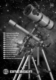
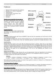
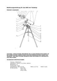
All parts (Fig. 1-3)<br />
Telescope tube<br />
Fin<strong>de</strong>r scope or LED fin<strong>de</strong>r scope<br />
Adjusting screws (fin<strong>de</strong>r scopes only)<br />
Barrel opening<br />
Objective<br />
Eyepiece connection<br />
Focus wheel<br />
Tube rings<br />
Mount<br />
Accessory tray<br />
Adjusting-screws (tripod)<br />
Fixing bracket (accessories tray)<br />
Tripod legs<br />
Flexible shaft for <strong>de</strong>clination adjustment<br />
Flexible shaft for right ascension adjustment<br />
Tripod spi<strong>de</strong>r<br />
Weight + pole<br />
3 eyepieces (Ø 31.7mm / 11 /4”) f=20mm f = 12mm f = 4mm<br />
Star diagonal prism<br />
Umkehrlinse 1,5x<br />
21 Barlow lens<br />
HINT:<br />
The right ascension axis (green line, illustration 16) is<br />
also called the axis of si<strong>de</strong>real time on the meridian.<br />
The <strong>de</strong>clination axis (blue line, illustration 16) is also<br />
called the elevation axis.<br />
Parts (Fig. 16): The Mount<br />
A Main tube clamp<br />
B Focus wheel<br />
C Scale of the <strong>de</strong>clination-axis<br />
D Fixing screw of the <strong>de</strong>clination-axis<br />
E Fine-adjustment of the <strong>de</strong>clination-axis<br />
F Scale for setting <strong>de</strong>grees of latitu<strong>de</strong><br />
G Latitu<strong>de</strong> adjustment setting and adjusting screw<br />
H Counterweight with fixing screw<br />
I Right ascension axis setting screw<br />
J Right ascension axis scale<br />
K Right ascension axis fine adjustment<br />
L Fixing screw for horizontal adjustment<br />
M Hol<strong>de</strong>r for optional R.A. motor<br />
N Clutch for R.A. motor<br />
O Transmission gear for R.A. motor<br />
Part I – Construction<br />
1. General/Location:<br />
These instructions <strong>de</strong>tail the assembly and use of refracting and<br />
reflecting telescopes with equatorial mountings (also called<br />
German mountings).<br />
Parts of these instructions hence contain differing instructions for<br />
the differing telescope mo<strong>de</strong>ls.<br />
Before you begin construction, you must choose a suitable<br />
location for your telescope.<br />
It will help you, if you build this appliance in a place, where you<br />
have a clear view of the skies, a stable footing and sufficient<br />
space around you.<br />
Remove all the parts from the packaging first. Check, using the<br />
diagram, whether all the parts are there.<br />
Important: Only do the screws up finger tight and avoid over<br />
tightening them.<br />
2. Tripod<br />
The tripod legs are pre-installed and already connected to the<br />
tripod head (illustration 5, X) and tripod spi<strong>de</strong>r (illustration 1, 16).<br />
Remove the tripod from it’s packaging and place it upright with<br />
the feet at the base. Take two of the legs and carefully pull them<br />
apart until they are in the fully open position. The entire weight of<br />
the tripod rests on one leg during this procedure. Then set the<br />
tripod upright again.<br />
Now extend each individual tripod leg to the <strong>de</strong>sired length (see<br />
illustration 4) and then tighten the clamping screw on each<br />
(illustration 4, 11) (a total of 3) until they are all hand tight. Do<br />
not overtighten them. The clamping screws serve to set the<br />
tripod leg interior segments to the <strong>de</strong>sired height.<br />
- 51 -<br />
HINT:<br />
A small spirit level, placed on the accessory tray, may<br />
help you to setup you telescope in level.<br />
3. Mounting<br />
Next the mounting (illustration 1, 9) is fastened to the tripod head<br />
(illustration 5, X). To do so insert the mounting from above in the<br />
tripod head and turn the knurled screw hand tight from below.<br />
First prepare the mount (Fig. 1, 9), put the weight on the weight<br />
shaft pole (Fig. 7, X) and then screw it securely into the mount<br />
from below.<br />
The tube ring (Fig. 1+3, 8) should now be placed on the mount<br />
and fixed with the screw (Fig. 8, X).<br />
4. Accessory tray:<br />
The accessories tray (illustrations 1, 3, and 10) is inserted with<br />
the flat si<strong>de</strong> down centrally on the tripod spi<strong>de</strong>r (illustration 1, 16)<br />
and mounted in place by turning clockwise once (60°) (illustration<br />
6). The three fittings of the accessories tray must be aligned<br />
with the tripod spi<strong>de</strong>r retaining fittings and fixed in place by<br />
them.<br />
5. Tube:<br />
To mount the telescope tube (Fig. 1, 1) you undo the screw on<br />
the tube ring (Fig. 9, X) and open up the ring.<br />
Now you place the tube in the centre of ring and close the ring<br />
up. Now secure the mounting by tightening the screw.<br />
Note: The main tube clamp may have 2 screws <strong>de</strong>pending on<br />
mo<strong>de</strong>l (ill. 9b). Mounting the main tube is in principle<br />
as given here.<br />
6. Inserting the eyepiece<br />
6.1. On refracting telescopes<br />
Two eyepieces (Fig. 2, 18) and a star diagonal prism (Fig. 2, 19)<br />
are supplied as standard with this telescope.<br />
With the eyepieces, you can <strong>de</strong>ci<strong>de</strong> which magnification you<br />
want for your telescope.<br />
Before you insert the eyepiece and the star diagonal prism, you<br />
must remove the dust-protection-cap from the eyepiece<br />
connection tube (Fig. 1, 6).<br />
Loosen the screw (Fig. 12, X) on the eyepiece connection tube<br />
and insert the star diagonal prism. Retighten the screw (Fig. 12,<br />
X) on the eyepiece connection tube.<br />
Then open and close the clamping screw (ill. 13a, X) to fasten<br />
the 20 mm eyepiece in the zenith mirror in the same way.<br />
Make sure that the eyepiece is pointing vertically upwards.<br />
Otherwise loosen the screw (Fig. 12, X) on the eyepiece<br />
connection tube and rotate the star diagonal prism into the<br />
vertical position.<br />
6.2. On reflecting telescopes<br />
Please loosen the clamping screw on the eyepiece supports (fig.<br />
1, 6). Remove the eyepiece supplied (fig. 2,18) with the 20 mm<br />
maximum focal length and insert it directly in the eyepiece supports.<br />
Hand tighten the clamping screws (fig. 3b, X). Remove the<br />
dust cap from the main tube end.<br />
GB