- Page 1 and 2: TPE, TPED Series 2000 Installation
- Page 3 and 4: Декларация о соотв
- Page 5 and 6: TPE, TPED Series 2000 Installation
- Page 7 and 8: 1. Symbols used in this document (
- Page 9 and 10: 5.1.9 Connections Note If no extern
- Page 11 and 12: 5.2.8 Start/stop of pump Caution Wh
- Page 13 and 14: • Two protective earth conductors
- Page 15: 5.4 Signal cables • Use screened
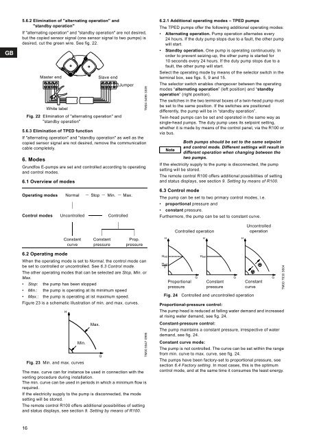
- Page 19 and 20: 8. Setting by means of control pane
- Page 21 and 22: 0. GENERAL 1. OPERATION 2. STATUS 3
- Page 23 and 24: 9.1.4 Fault log For both fault type
- Page 25 and 26: 9.3.4 Buttons on pump The operating
- Page 27 and 28: 13. External setpoint signal The se
- Page 29 and 30: The functions of the two indicator
- Page 31 and 32: 19. Maintenance and service 19.1 Cl
- Page 33 and 34: 23. Other technical data EMC (elect
- Page 35 and 36: INHALTSVERZEICHNIS 1. Sicherheitshi
- Page 37 and 38: 2. Allgemeine Informationen Die vor
- Page 39 and 40: 5.1.9 Anschlüsse Hinweis Wird kein
- Page 41 and 42: Arten von Netzen Dreiphasige E-Pump
- Page 43 and 44: Abb. 11 Anschluss eines einzelnen S
- Page 45 and 46: Gruppe 2 Gruppe 4 Gruppe 3 1: Digit
- Page 47 and 48: 6. Betriebs- und Regelungsarten Die
- Page 49 and 50: 7. Einstellungen über das Bedienfe
- Page 51 and 52: 8.4 Einstellen auf Betrieb mit MIN-
- Page 53 and 54: 9.1 Menü BETRIEB In diesem Menü e
- Page 55 and 56: 9.2.7 Anzeige des Schmierstatus der
- Page 57 and 58: 10. Einstellungen über das PC Tool
- Page 59 and 60: 15. Andere Bus-Protokolle Grundfos
- Page 61 and 62: 18. Notbetrieb (nur 11-22 kW) Warnu
- Page 63 and 64: 21. Technische Daten - dreiphasige
- Page 65 and 66: Schalldruckpegel Einphasige Pumpen:
- Page 67 and 68:
22. Caractéristiques techniques -
- Page 69 and 70:
5.1.9 Raccordements Nota Si aucun i
- Page 71 and 72:
5.2.8 Marche/arrêt de la pompe Pr
- Page 73 and 74:
• Deux conducteurs de protection
- Page 75 and 76:
5.4 Câbles de signaux • Utiliser
- Page 77 and 78:
Mode courbe constante : La pompe n'
- Page 79 and 80:
8. Réglage au moyen du panneau de
- Page 81 and 82:
0. GENERAL 1. FONCTIONNEMENT 2. ETA
- Page 83 and 84:
9.1.4 Journal des défauts Le R100
- Page 85 and 86:
9.3.4 Touches de la pompe Les touch
- Page 87 and 88:
13. Signal externe du point de cons
- Page 89 and 90:
Les fonctions des deux voyants et d
- Page 91 and 92:
19. Maintenance et entretien 19.1 N
- Page 93 and 94:
23. Autres caractéristiques techni
- Page 95 and 96:
INDICE 1. Simboli utilizzati in que
- Page 97 and 98:
5.1 Collegamento elettrico - pompe
- Page 99 and 100:
5.2 Collegamento elettrico- pompe t
- Page 101 and 102:
Gruppo 4 Fig. 9 Morsetti di conness
- Page 103 and 104:
Gruppo 2: Uscita (segnale del relè
- Page 105 and 106:
5.6.2 Eliminazione del "funzionamen
- Page 107 and 108:
7. Impostazione dal pannello di con
- Page 109 and 110:
8.4 Impostazione del funzionamento
- Page 111 and 112:
9.1 Menu FUNZIONAMENTO La prima sch
- Page 113 and 114:
9.2.7 Stato della lubrificazione de
- Page 115 and 116:
10. Impostazione tramite l'PC Tool
- Page 117 and 118:
14. Segnale di bus La pompa support
- Page 119 and 120:
18. Funzionamento di emergenza (sol
- Page 121 and 122:
21. Dati tecnici - pompe trifase, 0
- Page 123 and 124:
Livello di pressione acustica Pompe
- Page 125 and 126:
1. Símbolos utilizados en este doc
- Page 127 and 128:
5.1.9 Conexiones Nota Si no se cone
- Page 129 and 130:
5.2.8 Arranque/parada de la bomba P
- Page 131 and 132:
• Dos conductores de tierra de pr
- Page 133 and 134:
5.4 Cables de señal • Utilizar c
- Page 135 and 136:
6.3.1 Guía de selección del modo
- Page 137 and 138:
8. Ajuste mediante el panel de cont
- Page 139 and 140:
0. GENERAL 1. FUNCIONAMIENTO 2. EST
- Page 141 and 142:
9.1.4 Registro de fallos Para ambos
- Page 143 and 144:
9.3.4 Botones de la bomba Los boton
- Page 145 and 146:
13. Señal externa del punto de aju
- Page 147 and 148:
Las funciones de las dos luces test
- Page 149 and 150:
19. Mantenimiento y reparación 19.
- Page 151 and 152:
23. Otros datos técnicos EMC (comp
- Page 153 and 154:
ÍNDICE 1. Símbolos utilizados nes
- Page 155 and 156:
5.1 Ligação eléctrica - bombas m
- Page 157 and 158:
5.2 Ligação eléctrica - bombas t
- Page 159 and 160:
Grupo 4 Fig. 9 Terminais de ligaç
- Page 161 and 162:
Grupo 2: Saída (sinal de relé, te
- Page 163 and 164:
5.6.2 Eliminação da "operação a
- Page 165 and 166:
7. Configuração através do paine
- Page 167 and 168:
8.4 Configuração para funcionamen
- Page 169 and 170:
9.1 Menu FUNCIONAMENTO O primeiro v
- Page 171 and 172:
9.2.7 Estado da lubrificação dos
- Page 173 and 174:
10. Configuração através do PC T
- Page 175 and 176:
14. Sinal bus A bomba suporta comun
- Page 177 and 178:
18. Funcionamento de emergência (a
- Page 179 and 180:
21. Características técnicas - bo
- Page 181 and 182:
Bombas trifásicas: 24. Eliminaçã
- Page 183 and 184:
23. Άλλα τεχνικά χαρ
- Page 185 and 186:
5.1.8 Εκκίνηση/παύση
- Page 187 and 188:
5.2.8 Εκκίνηση/παύση
- Page 189 and 190:
• Δύο προστατευτικ
- Page 191 and 192:
5.4 Καλώδια σήματος
- Page 193 and 194:
Πρόγραμμα σταθερής
- Page 195 and 196:
8. Ρύθμιση μέσω του
- Page 197 and 198:
0. ΓΕΝΙΚΑ 1. ΛΕΙΤΟΥΡΓ
- Page 199 and 200:
9.1.4 Ημερολόγιο βλαβ
- Page 201 and 202:
Σημείωση Οι ενδείξ
- Page 203 and 204:
13. Εξωτερικό σήμα σ
- Page 205 and 206:
Οι λειτουργίες των
- Page 207 and 208:
Χρησιμοποιήστε τις
- Page 209 and 210:
22. Τεχνικά χαρακτηρ
- Page 211 and 212:
24. Απόρριψη Το προϊ
- Page 213 and 214:
1. Symbolen die in dit document geb
- Page 215 and 216:
5.1.9 Aansluitingen N.B. Verbind kl
- Page 217 and 218:
5.2.8 In- en uitschakelen van de po
- Page 219 and 220:
• Twee aarddraden met dezelfde ad
- Page 221 and 222:
5.4 Signaalkabels • Gebruik afges
- Page 223 and 224:
6.3.1 Richtlijn voor de keuze van r
- Page 225 and 226:
8. Instelling d.m.v. bedieningspane
- Page 227 and 228:
0. ALGEMEEN 1. BEDRIJF 2. STATUS 3.
- Page 229 and 230:
9.1.4 Overzicht van storingen en wa
- Page 231 and 232:
N.B. Storing omvat activiteiten die
- Page 233 and 234:
13. Signaal van externe gewenste wa
- Page 235 and 236:
De onderstaande tabel geeft een ove
- Page 237 and 238:
19. Onderhoud en service 19.1 Reini
- Page 239 and 240:
23. Overige technische gegevens EMC
- Page 241 and 242:
INNEHÅLLSFÖRTECKNING 1. Symboler
- Page 243 and 244:
5.1 Elanslutning: 1-faspumpar Varni
- Page 245 and 246:
5.2 Elanslutning: 3-faspumpar, 0,75
- Page 247 and 248:
Grupp 4 Fig. 9 Anslutningsplintar -
- Page 249 and 250:
Grupp 4: Kommunikationskabel (8-sti
- Page 251 and 252:
5.6.2 Eliminering av "alternerande
- Page 253 and 254:
7. Inställning från manöverpanel
- Page 255 and 256:
8.4 Inställning av drift på min.k
- Page 257 and 258:
9.1 Menyn DRIFT Detta är den förs
- Page 259 and 260:
9.2.7 Motorlagrens smörjningsstatu
- Page 261 and 262:
10. Inställning med hjälp av Grun
- Page 263 and 264:
16. Indikeringslampor och meddeland
- Page 265 and 266:
18. Nöddrift (endast 11-22 kW) Var
- Page 267 and 268:
21. Tekniska data - 3-faspumpar, 0,
- Page 269 and 270:
Ljudtrycksnivå 1-faspumpar: < 70 d
- Page 271 and 272:
1. Tässä julkaisussa käytettäv
- Page 273 and 274:
5.1.9 Liitännät Huomaa Jos ulkois
- Page 275 and 276:
5.2.8 Pumpun käynnistys/pysäytys
- Page 277 and 278:
• Käytetään kahta suojamaadoit
- Page 279 and 280:
5.4 Signaalikaapelit • Käytä ul
- Page 281 and 282:
6.3.1 Säätötavan valintaohje jä
- Page 283 and 284:
8. Asetusten tekeminen ohjauspaneel
- Page 285 and 286:
0. YLEISTÄ 1. KÄYTTÖ 2. OLOTILA
- Page 287 and 288:
9.1.4 Vikaloki R100:ssa on lokitoim
- Page 289 and 290:
9.3.4 Painikkeet pumpussa Ohjauspan
- Page 291 and 292:
13. Ulkoinen asetuspistesignaali As
- Page 293 and 294:
Merkkivalojen ja signaalireleen toi
- Page 295 and 296:
19. Kunnossapito ja huolto 19.1 Moo
- Page 297 and 298:
23. Muut tekniset tiedot EMC (sähk
- Page 299 and 300:
INDHOLDSFORTEGNELSE 1. Symboler bru
- Page 301 and 302:
5.1 El-tilslutning af 1-fasede pump
- Page 303 and 304:
5.2 El-tilslutning af 3-fasede pump
- Page 305 and 306:
Gruppe 4 Fig. 9 Tilslutningsklemmer
- Page 307 and 308:
Gruppe 3: Netforsyning (klemme L1,
- Page 309 and 310:
5.6.3 Sådan fjernes TPED-funktione
- Page 311 and 312:
7. Indstilling ved hjælp af betjen
- Page 313 and 314:
8.4 Sådan indstilles min. kurve-dr
- Page 315 and 316:
9.1 Menu DRIFT Dette er det første
- Page 317 and 318:
9.2.7 Smørestatus for motorens lej
- Page 319 and 320:
10. Indstilling ved hjælp af PC To
- Page 321 and 322:
16. Signallamper og melderelæ Pump
- Page 323 and 324:
18. Nøddrift (kun 11-22 kW) Advars
- Page 325 and 326:
21. Tekniske data - 3-fasede pumper
- Page 327 and 328:
Lydtryksniveau 1-fasede pumper: < 7
- Page 329 and 330:
21. Dane techniczne - pompy 3-fazow
- Page 331 and 332:
5.1 Podłączenie elektryczne - pom
- Page 333 and 334:
5.2 Podłączenie elektryczne - pom
- Page 335 and 336:
Grupa 4 Rys. 9 Zaciski przyłączen
- Page 337 and 338:
Grupa 2: Wyjścia (przekaźnik sygn
- Page 339 and 340:
5.6.2 Rezygnacja z "pracy naprzemie
- Page 341 and 342:
7. Nastawy z poziomu panelu steruj
- Page 343 and 344:
8.4 Ustawienie charakterystyki Min.
- Page 345 and 346:
9.1 Menu PRACA Pierwszym ekranem te
- Page 347 and 348:
9.2.7 Stan nasmarowania łożysk si
- Page 349 and 350:
10. Ustawienia przy pomocy PC Tool
- Page 351 and 352:
14. Sygnał bus Pompa zapewnia moż
- Page 353 and 354:
18. Praca awaryjna (tylko 11-22 kW)
- Page 355 and 356:
21. Dane techniczne - pompy 3-fazow
- Page 357 and 358:
Poziom ciśnienia akustycznego Pomp
- Page 359 and 360:
16. Другие стандарты
- Page 361 and 362:
6.1 Подключение элек
- Page 363 and 364:
6.2 Подключение элек
- Page 365 and 366:
Группа 4 Рис. 9 Клемм
- Page 367 and 368:
Группа 1: Входы • ВК
- Page 369 and 370:
7. Способы регулиро
- Page 371 and 372:
8. Установка параме
- Page 373 and 374:
9.2 Установка значен
- Page 375 and 376:
10.1 Меню ЭКСПЛУАТАЦ
- Page 377 and 378:
10.2.6 Часы эксплуата
- Page 379 and 380:
10.3.8 Подтверждение
- Page 381 and 382:
При регулировании
- Page 383 and 384:
Функции двух свето
- Page 385 and 386:
Используйте винты
- Page 387 and 388:
Используются станд
- Page 389 and 390:
25. Утилизация отход
- Page 391 and 392:
22. Műszaki adatok - háromfázis
- Page 393 and 394:
5.1 Elektromos bekötés - egyfázi
- Page 395 and 396:
5.2 Elektromos bekötés - háromf
- Page 397 and 398:
4. csoport 9. ábra Csatlakozó sor
- Page 399 and 400:
3. csoport: Hálózati feszültség
- Page 401 and 402:
5.6.2 A "váltott üzemmód" és a
- Page 403 and 404:
7. Beállítás a kezelőpanelen, e
- Page 405 and 406:
8.4 Min. görbe beállítása Tarts
- Page 407 and 408:
9.1 ÜZEMELTETÉS menü Ez az első
- Page 409 and 410:
9.2.7 Motor csapágyak kenési áll
- Page 411 and 412:
10. Beállítások a PC Tool E-prod
- Page 413 and 414:
16. Jelzőfények és jelzőrelé A
- Page 415 and 416:
18. Szükségüzem (csak 11-22 kW)
- Page 417 and 418:
21. Műszaki adatok - háromfázis
- Page 419 and 420:
Zajszint Egyfázisú szivattyúk: <
- Page 421 and 422:
21. Tehnični podatki - trifazne č
- Page 423 and 424:
5.1 Električna priključitev - eno
- Page 425 and 426:
5.2 Električna priključitev - tri
- Page 427 and 428:
Skupina 4 Slika 9 Priključki - TPE
- Page 429 and 430:
Skupina 4: Komunikacijski kabel (8-
- Page 431 and 432:
5.6.2 Preprečevanje "izmenjujočeg
- Page 433 and 434:
7. Nastavljanje preko kontrolnega p
- Page 435 and 436:
8.4 Nastavitev na delovanje na min.
- Page 437 and 438:
9.1 Meni DELOVANJE Prvi prikaz v te
- Page 439 and 440:
9.2.7 Status podmazanosti ležajev
- Page 441 and 442:
10. Nastavljanje s pomočjo "PC Too
- Page 443 and 444:
14. Bus signal Črpalka podpira ser
- Page 445 and 446:
18. Delovanje v sili - bypass (samo
- Page 447 and 448:
21. Tehnični podatki - trifazne č
- Page 449 and 450:
Trifazne črpalke: 24. Odstranitev
- Page 451 and 452:
22. Tehnički podaci - trofazne crp
- Page 453 and 454:
5.1 Električno spajanje - jednofaz
- Page 455 and 456:
5.2 Električno spajanje - trofazne
- Page 457 and 458:
Grupa 4 Slika 9 Stezaljke - TPED se
- Page 459 and 460:
Grupa 2: Izlaz (signal za relej, st
- Page 461 and 462:
5.6.2 Uklanjanje "izmjeničnog rada
- Page 463 and 464:
7. Podešavanje putem upravljačke
- Page 465 and 466:
8.4 Podešavanje na minimalnu krivu
- Page 467 and 468:
9.1 Izbornik RAD Prva ekranska slik
- Page 469 and 470:
9.2.7 Status podmazivanja ležajeva
- Page 471 and 472:
10. Postavljanje pomoću alata PC T
- Page 473 and 474:
14. Sabirnički signal Crpka podrž
- Page 475 and 476:
18. Rad u slučaju nužde (samo 11-
- Page 477 and 478:
21. Tehnički podaci - trofazne crp
- Page 479 and 480:
Razina zvučnog tlaka Jednofazne cr
- Page 481 and 482:
21. Tehnički podaci - trofazne pum
- Page 483 and 484:
5.1 Elektro povezivanja - monofazne
- Page 485 and 486:
5.2 Elektro povezivanje - trofazne
- Page 487 and 488:
Grupa 4 Slika 9 Terminali - TPED se
- Page 489 and 490:
Grupa 3: Glavno napajanje (terminal
- Page 491 and 492:
5.6.2 Uklanjanje "naizmeničnog rad
- Page 493 and 494:
7. Podešavanje preko kontrolne plo
- Page 495 and 496:
8.4 Podešavanje na minimalnu radnu
- Page 497 and 498:
9.1 Meni RAD Prvi displej u ovom me
- Page 499 and 500:
9.2.7 Status podmazivanja motornih
- Page 501 and 502:
10. Podešavanje preko PC Tool E-pr
- Page 503 and 504:
16. Indikacione lampice i signalni
- Page 505 and 506:
18. Pomoćni rad (samo 11-22 kW) Up
- Page 507 and 508:
21. Tehnički podaci - trofazne pum
- Page 509 and 510:
Nivo pritiska buke Monofazne pumpe:
- Page 511 and 512:
1. Simboluri folosite în acest doc
- Page 513 and 514:
5.1.9 Conexiuni Notă Dacă nu este
- Page 515 and 516:
5.2.8 Pornirea/oprirea pompei Aten
- Page 517 and 518:
• Doi conductori de împământar
- Page 519 and 520:
5.4 Cabluri de semnal • Utilizaţ
- Page 521 and 522:
6.3.1 Ghid pentru alegerea modului
- Page 523 and 524:
8. Setarea cu ajutorul panoului de
- Page 525 and 526:
0. GENERALITĂŢI 1. FUNCŢIONARE 2
- Page 527 and 528:
9.1.4 Jurnal de avarii Pentru ambel
- Page 529 and 530:
9.3.4 Butoanele pompei Butoanele de
- Page 531 and 532:
13. Semnal extern prag programat Pr
- Page 533 and 534:
Funcţiile celor doi indicatori lum
- Page 535 and 536:
19. Întreţinere şi reparaţii 19
- Page 537 and 538:
23. Alte date tehnice EMC (compatib
- Page 539 and 540:
СЪДЪРЖАНИЕ 1. Мерки
- Page 541 and 542:
2. Обща информация Т
- Page 543 and 544:
5.1.8 Старт/стоп на по
- Page 545 and 546:
Типове мрежи Трифа
- Page 547 and 548:
Фиг. 12 Свързване на
- Page 549 and 550:
5.4 Кабели за сигнал
- Page 551 and 552:
Режим Константна к
- Page 553 and 554:
7.4 Старт/стоп на пом
- Page 555 and 556:
0. ОБЩИ 1. РАБОТА 2. СТ
- Page 557 and 558:
9.1.4 Регистър на неи
- Page 559 and 560:
9.3.3 Сигнално реле (с
- Page 561 and 562:
Приоритет на настр
- Page 563 and 564:
16. Светлинни индика
- Page 565 and 566:
17. Изолационно съпр
- Page 567 and 568:
20. Технически данни
- Page 569 and 570:
Като се инсталира п
- Page 571 and 572:
OBSAH 1. Bezpečnostní pokyny Stra
- Page 573 and 574:
4. Mechanická instalace Pokyn K z
- Page 575 and 576:
Skupina 4 0-10 V 0/4-20 mA 4-20 mA
- Page 577 and 578:
NC C NO L1 L2 L3 0-10 V 0/4-20 mA 4
- Page 579 and 580:
5.3.5 Motorová ochrana Čerpadlo n
- Page 581 and 582:
5.4 Signální kabely • Pro exter
- Page 583 and 584:
6.3.1 Návod k volbě druhu regulac
- Page 585 and 586:
8. Nastavování na ovládacím pan
- Page 587 and 588:
0. OBECNĚ 1. PROVOZ 2. PROVOZNÍ S
- Page 589 and 590:
9.1.4 Poruchové hlášení Pro oba
- Page 591 and 592:
Pokyn Možnosti Porucha a Alarm se
- Page 593 and 594:
13. Externí signál požadované h
- Page 595 and 596:
Funkce obou signálních světel a
- Page 597 and 598:
19. Údržba a servis 19.1 Čiště
- Page 599 and 600:
23. Jiné technické údaje EMC (el
- Page 601 and 602:
OBSAH 1. Bezpečnostné pokyny Stra
- Page 603 and 604:
2. Všeobecné informácie Tento mo
- Page 605 and 606:
5.1.9 Prípojky Dôležité Ak nie
- Page 607 and 608:
5.2.8 Štart/stop čerpadla Pozor A
- Page 609 and 610:
Obr. 11 Pripojenie jednotlivého oc
- Page 611 and 612:
Skupina 2 Skupina 4 Skupina 3 1: Di
- Page 613 and 614:
6. Režimy E-čerpadlá Grundfos s
- Page 615 and 616:
7. Nastavovanie na ovládacom panel
- Page 617 and 618:
8.4 Nastavenie režimu prevádzky p
- Page 619 and 620:
9.1 Menu PREVÁDZKA Prvé displejov
- Page 621 and 622:
9.2.7 Stav mazania motorových lož
- Page 623 and 624:
10. Nastavenie pomocou 'PC Tool E-p
- Page 625 and 626:
14. Bus signál Čerpadlo podporuje
- Page 627 and 628:
18. Núdzová prevádzka (len 11-22
- Page 629 and 630:
21. Technické údaje - trojfázov
- Page 631 and 632:
Trojfázové čerpadlá: 24. Likvid
- Page 633 and 634:
1. Bu dokümanda kullanılan sembol
- Page 635 and 636:
5.1.9 Bağlantılar Not Harici açm
- Page 637 and 638:
5.2.8 Pompanın çalıştırılmas
- Page 639 and 640:
• Bir iletken terminal kutusundak
- Page 641 and 642:
5.4 Sinyal kabloları • Harici a
- Page 643 and 644:
6.3.1 Sistem türüne göre kontrol
- Page 645 and 646:
8. Üç-fazlı pompalar, kontrol pa
- Page 647 and 648:
0. GENEL 1. ÇALIŞMA 2. DURUM 3. K
- Page 649 and 650:
9.1.4 Arıza kaydı Alarm ve uyarı
- Page 651 and 652:
9.3.4 Pompa üzerindeki düğmeler
- Page 653 and 654:
13. Harici ayar noktası sinyali Ay
- Page 655 and 656:
İki gösterge ışığının ve si
- Page 657 and 658:
19. Bakım ve servis 19.1 Motorun t
- Page 659 and 660:
23. Diğer teknik veriler EMC (EN 6
- Page 661 and 662:
YETKİLİ GRUNDFOS SERVİSLERİ SER
- Page 663 and 664:
1. Selles dokumendis kasutatud süm
- Page 665 and 666:
5.1.9 Ühendused Märkus Kui välis
- Page 667 and 668:
5.2.8 Pumba käivitamine/peatamine
- Page 669 and 670:
5.3.3 Reservkaitsmed Soovitatavad k
- Page 671 and 672:
5.4 Signaalikaablid • Kasuta väl
- Page 673 and 674:
6.3.1 Juhend juhtimisrežiimi valik
- Page 675 and 676:
8. Seadistamine juhtimispaneelilt,
- Page 677 and 678:
0. ÜLDMENÜÜ 1. TÖÖMENÜÜ 2. S
- Page 679 and 680:
9.1.4 Vealogi Mõlemale vigade tü
- Page 681 and 682:
9.3.4 Pumba nupud Juhtimispaneelil
- Page 683 and 684:
13. Välise seadeväärtuse signaal
- Page 685 and 686:
Kahe indikaatortule ja signaalrelee
- Page 687 and 688:
19. Ekspluatatsioon ja hooldus 19.1
- Page 689 and 690:
23. Teised tehnilised andmed EMC (e
- Page 691 and 692:
TURINYS 1. Šiame dokumente naudoja
- Page 693 and 694:
5.1 Vienfazių siurblių elektros j
- Page 695 and 696:
5.2 Trifazių 0,75-7,5 kW siurblių
- Page 697 and 698:
Grupė 4 9 pav. TPED serija 2000 gn
- Page 699 and 700:
Grupė 4: Ryšio kabelis (8 kaište
- Page 701 and 702:
5.6.2 Darbo pakaitomis režimo ir r
- Page 703 and 704:
7. Nustatymas valdymo skydeliu, vie
- Page 705 and 706:
8.4 Min. kreivės režimo įjungima
- Page 707 and 708:
9.1 Meniu DARBAS Pirmasis ekranas
- Page 709 and 710:
9.2.7 Variklio guolių tepimo būkl
- Page 711 and 712:
10. Nustatymas naudojantis programa
- Page 713 and 714:
14. Magistralės signalas Siurblys
- Page 715 and 716:
18. Avarinis darbas (tik 11-22 kW)
- Page 717 and 718:
21. 0,75-7,5 kW trifazių siurblių
- Page 719 and 720:
Trifaziai siurbliai: 24. Atliekų t
- Page 721 and 722:
1. Šajā dokumentā lietotie simbo
- Page 723 and 724:
5.1.9. Savienojumi Piezīme Ja nav
- Page 725 and 726:
5.2.8. Sūkņa ieslēgšana/izslēg
- Page 727 and 728:
5.3.3. Rezerves drošinātāji Iete
- Page 729 and 730:
5.4. Signālkabeļi • Jālieto ek
- Page 731 and 732:
6.3.1. Vadības režīma izvēle sa
- Page 733 and 734:
8. Iestatīšana ar vadības pults
- Page 735 and 736:
0. GALVENĀ IZVĒLNE 1. DARBĪBA 2.
- Page 737 and 738:
9.1.4. Bojājumu reģistrs Abiem bo
- Page 739 and 740:
9.3.4. Sūkņa pogas Darba pogām u
- Page 741 and 742:
13. Ārējās uzdotās vērtības s
- Page 743 and 744:
Divu indikatora kontrollampiņu un
- Page 745 and 746:
19. Tehniskā apkope 19.1. Motora t
- Page 747 and 748:
23. Citi tehniskie dati EMC (elektr
- Page 749 and 750:
ЗМIСТ 1. Значення си
- Page 751 and 752:
5.1 Електричне під'є
- Page 753 and 754:
5.2 Електричне під'є
- Page 755 and 756:
Група 4 Рис. 9 З'єдну
- Page 757 and 758:
Група 2: Вихід (сигн
- Page 759 and 760:
5.6.2 Видалення "змін
- Page 761 and 762:
7. Введення установ
- Page 763 and 764:
8.4 Установка в режи
- Page 765 and 766:
9.1 Меню РОБОТА Перш
- Page 767 and 768:
9.2.7 Стан змащення п
- Page 769 and 770:
10. Задання установо
- Page 771 and 772:
14. Сигнал по шині На
- Page 773 and 774:
17. Опір ізоляції Ув
- Page 775 and 776:
20. Технічна інформа
- Page 777 and 778:
23. Інші технічні да
- Page 779 and 780:
1. Installation in the USA and Cana
- Page 781:
96782378 0110 Repl. 96782378 0109 w