Clean Air Boxes (CAB) Series User Manual www.bullard.com
Clean Air Boxes (CAB) Series User Manual www.bullard.com
Clean Air Boxes (CAB) Series User Manual www.bullard.com

Create successful ePaper yourself
Turn your PDF publications into a flip-book with our unique Google optimized e-Paper software.
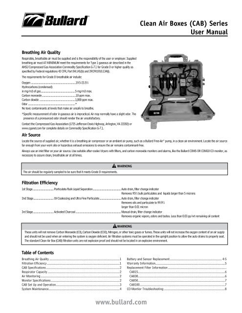
Breathing <strong>Air</strong> Quality<br />
Respirable, breathable air must be supplied and is the responsibility of the user or employer. Supplied<br />
breathing air must AT MINIMUM meet the requirements for Type 1 gaseous air described in the<br />
ANSI/Compressed Gas Association Commodity Specification G-7.1 for Grade D or higher quality as<br />
specified by Federal regulations 42 CFR, Part 84.141(b) and 29CFR1910.134(i).<br />
The requirements for Grade D breathable air include:<br />
Oxygen .........................................................................19.5-23.5%<br />
Hydrocarbons (condensed)<br />
in mg/m3 of gas ........................................................5 mg/m3 max.<br />
Carbon monoxide .......................................................10 ppm max.<br />
Carbon dioxide ..........................................................1,000 ppm max.<br />
Odor .............................................................................*<br />
No toxic contaminants at levels that make air unsafe to breathe.<br />
* Specific measurement of odor in gaseous air is impractical. <strong>Air</strong> may normally have a slight odor. The<br />
presence of a pronounced odor should render the air unsatisfactory.<br />
Contact the Compressed Gas Association (1725 Jefferson Davis Highway, Arlington, VA 22202) or<br />
<strong>www</strong>.cganet.<strong>com</strong> for <strong>com</strong>plete details on Commodity Specification G-7.1.<br />
<strong>Air</strong> Source<br />
Locate the source of supplied air, whether it is a breathing air <strong>com</strong>pressor or an ambient air pump, such as a Bullard Free-<strong>Air</strong> ® pump, in a clean air environment. Locate the air source<br />
far enough from your work site or hazardous exhaust emissions to ensure the air remains contaminant-free.<br />
Always use an inlet filter on your air source. Use suitable after-cooler/dryers with filters, and carbon monoxide monitors and alarms, like the Bullard COM5 OR COM10 CO monitor, as<br />
necessary to assure clean, breathable air at all times.<br />
wArning<br />
The air should be regularly sampled to be sure that it meets Grade D requirements.<br />
Filtration Efficiency<br />
1st Stage ..................................Particulate/Bulk Liquid Separation .............................................. Auto drain, filter change indicator<br />
Removes 95% bulk particulates and liquids larger than 5 microns<br />
2nd Stage .................................Oil Coalescing and Ultra Fine Particulate ................................... Auto drain, filter change indicator<br />
Removes oils and particulate to 99.9%<br />
larger than 0.01 micron<br />
3rd Stage ..................................Activated Charcoal .......................................................................... <strong>Manual</strong> drain, filter change indicator<br />
Removes organic vapors, odors and tastes. Less than 0.03 pp/wt remaining oil content<br />
wArning<br />
These units will not remove Carbon Monoxide (CO), Carbon Dioxide (CO2), Nitrogen, or other toxic gases or fumes. These units will not increase the oxygen content of an air supply<br />
and should not be used when air entering the system is oxygen deficient. <strong>Air</strong> filtration systems must be operated in the upright position to allow the auto drains to properly seat.<br />
The standard <strong>Clean</strong> <strong>Air</strong> Box (<strong>CAB</strong>) filtration units are not explosion proof and should not be located in an explosive environment.<br />
Table of Contents<br />
Breathing <strong>Air</strong> Quality .........................................................................................1<br />
Filtration Efficiency ............................................................................................1<br />
<strong>CAB</strong> Specifications .............................................................................................2<br />
Respirator Capacity ...........................................................................................2<br />
<strong>Air</strong> Monitoring ....................................................................................................2<br />
Monitor Specifications .......................................................................................2<br />
<strong>CAB</strong> Set Up and Operation.................................................................................3<br />
System Maintenance ..........................................................................................4<br />
<strong>www</strong>.<strong>bullard</strong>.<strong>com</strong><br />
<strong>Clean</strong> <strong>Air</strong> <strong>Boxes</strong> (<strong>CAB</strong>) <strong>Series</strong><br />
<strong>User</strong> <strong>Manual</strong><br />
Battery and Sensor Replacement .................................................................. 4-5<br />
Warranty Information ........................................................................................5<br />
Replacement Filter Information ..........................................................................<br />
<strong>CAB</strong>15 ..............................................................................................................6<br />
<strong>CAB</strong>30 ..............................................................................................................6<br />
<strong>CAB</strong>50 ..............................................................................................................7<br />
<strong>CAB</strong>100 ............................................................................................................7<br />
CO Montior Troubleshooting .............................................................................8
<strong>CAB</strong> Specifications/<strong>Air</strong> Monitoring/Monitor Specifications<br />
2<br />
<strong>CAB</strong> <strong>Clean</strong> <strong>Air</strong> Box Specifications and Parts information<br />
respirator Capacity<br />
The Bullard <strong>Clean</strong> <strong>Air</strong> Box is supplied with up to 8 quick-disconnect fittings. The actual<br />
number of respirators that may be connected to the <strong>CAB</strong> is dependent on the inlet<br />
pressure to the Bullard air filtration system and the air flow and pressure requirements<br />
of the respirator being worn. <strong>Air</strong> supply pressure ranges and approved hose lengths for<br />
a respirator can be found in the manufacturer’s <strong>User</strong> Instructions for the respirator.<br />
<strong>Air</strong> Monitoring<br />
The air flows through the CO monitor and a small amount (~0.5 lpm) is diverted through<br />
a preset internal regulator and flow restrictor, delivering a continuous flow of sample air<br />
to the sensor chamber. The monitor will analyze the air and display the CO concentration<br />
in parts-per-million (ppm). The Green LED located on the outside of the <strong>CAB</strong> will<br />
illuminate during normal operation when the CO level is below the CO alarm point (10<br />
ppm US and 5 ppm International). If the CO level rises above the alarm set point, the<br />
Red LED on the outside of the <strong>CAB</strong> will illuminate and an audible alarm will sound.<br />
The red CO alarm and green LED lights indicating normal operation are located on the<br />
face of the monitor inside the <strong>CAB</strong>15 <strong>Clean</strong> <strong>Air</strong> Box.<br />
Function Modes<br />
The knob on the front of the COM10 monitor sets the functions for the CO monitor and<br />
can be switched to RUN, TEST and CAL.<br />
Monitor Specs<br />
Operating Temperature ............................................................-4ºF to 120ºF (-20ºC to 48.89ºC)<br />
Humidity Range .................................................................................................................. 0 – 100%<br />
Sample Flow Rate ..................................................................................................................0.85 cfh<br />
Display ................................................................................................................................ 2 digit LCD<br />
Sensor Type ...........................................................................Electrochemical; Carbon Monoxide<br />
Range .................................................................................................................................0 – 99 ppm<br />
Calibration ...................................... <strong>Manual</strong> CO and Zero - Auto Cal ® ; No manualadjustments<br />
Alarm Setting...................................................................................10 ppm (5 ppm International)<br />
<strong>CAB</strong>15 <strong>Series</strong> <strong>CAB</strong>30 <strong>Series</strong> <strong>CAB</strong>50 <strong>Series</strong> <strong>CAB</strong>100 <strong>Series</strong><br />
Unit Dimensions 19” x 13” x 7” 22” x 14” x 7” 24” x 18” x 9” 27” x 20” x 10”<br />
weight 17 lbs 18 lbs 36 lbs 41 lbs<br />
inlet Fitting Size 1/2” 1/2” 1/2” 1/2”<br />
Outlets (1/4”) 1 2 4 8<br />
Maximum <strong>Air</strong> Flow 15scfm at 110 psi 30scfm at 110 psi 50scfm at 110 psi 100scfm at 110 psi<br />
(cfm/bar) 425 lpm at 7.5 bar 850 lpm at 7.5 bar 1415 lpm at 7.5 bar 4248 lpm at 7.5 bar<br />
remote Alarm Jack N Y Y Y<br />
Maximum inlet Pressure 150 psi 150 psi 150 psi 150 psi<br />
relief Valve 125 psi 125 psi 125 psi 125 psi<br />
Monitoring Inline Continuous CO Monitoring Inline Continuous CO Monitoring Inline Continuous CO Monitoring Inline Continuous CO Monitoring<br />
Power 12V DC or 110-220V AC 50/60Hz 12V DC or 110-220V AC 50/60Hz 12V DC or 110-220V AC 50/60Hz 12V DC or 110-220V AC 50/60Hz<br />
Shipping Dimensions 24.5” L x 17” W x 8” H 24.5” L x 17” W x 8” H 29” L x 22.5” W x 8.75” H 29” L x 22.5” W x 8.75” H<br />
rUn mode is the operation/detection mode. The monitor must be in the RUN mode<br />
to monitor the supplied breathing air. Supplied air must be turned on and flowing to<br />
the instrument while in this mode. When the supplied air is off or interrupted while the<br />
monitor is in the RUN mode, the low flow alarm will sound and LF will be displayed on<br />
the monitor until the supplied air is turned on.<br />
TEST mode allows for bump testing of the sensor or for silencing of the low flow alarm<br />
when supplied air is shut off. To perform a bump test, or zero gas, place the monitor in<br />
the TEST mode and flow the calibration gas into the center of the knob. The reading on<br />
the monitor should be 10 +/- 1 if applying CO gas. The reading on the monitor should<br />
be zero or 1 if applying the Zero gas. In the test mode, the supplied air will not be<br />
monitored and there is no need to turn the supplied air off when entering this mode. Unit<br />
must be zeroed if bump test is performed with 10 ppm CO gas.<br />
CAL mode is the calibration and zero calibration mode. When the monitor is switched<br />
to the CAL mode, the supplied air will not be flowing to the sensor and there is no need<br />
to shut off the supplied air. When in the CAL mode, (AC) AutoCal ® will be displayed.<br />
Pressing the On/Off button while in this mode will change the display to (AO) AutoZero.<br />
For calibration and zeroing instruction, see the Calibration section.<br />
F1 (fault) is indicated on the display when the cam valve is not positioned securely<br />
in one of these three modes.<br />
Error Codes<br />
rC indicates that the system requires a recalibration.<br />
lb indicates a low battery.<br />
Warning Signals ......................................................................... Normal Operation - Green Light<br />
High CO - Red Light<br />
High CO - Audible alarm (90db)<br />
Low Battery - Amber Light (Blinking)<br />
Low Battery - Audible alarm (chirp)<br />
Low Flow Alarm - Audible alarm (90db)<br />
Warranty ..................................................................................Two years on sensor and monitor<br />
Shielding .................................................................................................. Internal RFI/EMI coating<br />
<strong>www</strong>.<strong>bullard</strong>.<strong>com</strong>
<strong>CAB</strong> <strong>Clean</strong> <strong>Air</strong> Box Set Up and Operation<br />
wArning<br />
Always operate the <strong>CAB</strong> <strong>Clean</strong> <strong>Air</strong> Box in the upright position. Failure to <strong>com</strong>ply may<br />
result in one or all of the following:<br />
Auto drains will not function properly. This may result in the contamination of the<br />
CO monitor and cause water to be passed through the air supply hose and into the<br />
worker’s respirator.<br />
Auto drains may be<strong>com</strong>e clogged. See user instructions for information on cleaning<br />
or replacing auto drains.<br />
Filters may accumulate moisture and/or contaminants. See user instructions for<br />
information on replacing filter.<br />
Set Up and Operation<br />
Prior to hooking up the in<strong>com</strong>ing air supply lines, purge all moisture by running the air<br />
before connecting the <strong>CAB</strong>. Attach to in<strong>com</strong>ing air source; do not exceed 150 psi.<br />
Connect AC cord to power inlet on the side of the <strong>CAB</strong> and then plug cord into an AC<br />
power source.<br />
nOTE<br />
This unit may be operated using DC power or eight AA batteries if no AC power is<br />
available.<br />
Flip switch on Control Box to ON position. (Figure 1)<br />
Ensure the knob on the CO Monitor<br />
is rotated to the TEST position. This<br />
will prevent the Low Flow alarm from<br />
sounding during start up if no air is<br />
flowing. (Figure 2)<br />
Push the ON button located behind the<br />
front cover of the<br />
CO Monitor. (Figure 2)<br />
Fig. 1<br />
Wait for the 60 second countdown<br />
shown on the CO Monitor display<br />
screen.<br />
Calibrate the CO Monitor if necessary.<br />
See Calibration Instructions.<br />
On/Off<br />
Button<br />
Fig. 2<br />
Connect the remote alarm assembly<br />
(optional) to the remote alarm jack.<br />
nOTE<br />
The knob must be in RUN position for active monitoring of CO in the air supply.<br />
Attach respirators and adjust regulator to appropriate pressure per respirator<br />
manufacturer’s re<strong>com</strong>mendation. For units with independent regulators, adjust each<br />
regulator as appropriate for each outlet being used.<br />
Calibration and Zero-Point Process<br />
Zero-Point Adjustment<br />
nOTE:<br />
It is re<strong>com</strong>mended that the <strong>Clean</strong> <strong>Air</strong> box be under pressure with no air going<br />
through the outlet fitting when perfroming zero point adjustment or calibration.<br />
<strong>www</strong>.<strong>bullard</strong>.<strong>com</strong><br />
<strong>Clean</strong> <strong>Air</strong> <strong>Boxes</strong> (<strong>CAB</strong>) <strong>Series</strong><br />
<strong>User</strong> <strong>Manual</strong><br />
nOTE:<br />
If monitor has been relocated to a different working area and ambient<br />
temperatures change, allow the unit to stabilize for 15-20 minutes prior to Zero<br />
Point adjustment and calibration. Zero calibration should be performed before<br />
calibrating the monitor with CO gas. Bullard re<strong>com</strong>mends using impurity free test<br />
gas to re-zero whenever the zero point has drifted.<br />
Zero Adjustment Procedure<br />
Remove the front cover of the CO Monitor.<br />
Push the ON button. The unit will beep and begin a 60 second countdown.<br />
Rotate the knob located on the front of the CO Monitor to the CAL position.<br />
“AC” will appear on the display.<br />
Press and hold the On/Off button until it beeps.<br />
“AO” will now appear on the display.<br />
Attach the regulator to the zero gas cylinder.<br />
Insert the calibration connector fitting into the center of the knob on the front of the<br />
monitor.<br />
Open the cylinder valve fully. The flow rate is preset, so there is no need to adjust it.<br />
The red LED will continue to blink for approximately 90 seconds during which the zero<br />
adjustment process will take place.<br />
Watch for the green LED to begin blinking. This indicates a successful zero.<br />
With the zero air flowing, rotate the knob to the TEST position. The reading should be Co<br />
or Co1. If any other reading is displayed, repeat Zero Point Adjustment.<br />
Close the regulator on zero gas cylinder <strong>com</strong>pletely. Remove the calibration connector<br />
fitting from the center of the knob.<br />
With the in<strong>com</strong>ing air flowing, turn the knob to RUN.<br />
nOTE<br />
Knob must be in RUN position for active monitoring of CO in the air supply.<br />
wArning<br />
These units will not remove Carbon Monoxide (CO), Carbon Dioxide (CO2), Nitrogen,<br />
or other toxic gases or fumes. These units will not increase the oxygen content of an<br />
air supply and should not be used when air entering the system is oxygen deficient.<br />
<strong>Air</strong> filtration systems must be operated in the upright position to allow the auto<br />
drains to properly seat. The standard clean <strong>Air</strong> Box (<strong>CAB</strong>) filtration units are not<br />
explosion proof and should not be located in a non-explosive environment.<br />
Calibration instructions<br />
The COM5 and COM10 are Auto-Cal instruments. All calibration adjustments are made<br />
automatically.<br />
Monitor calibration should be performed monthly or whenever the reading may be<br />
questionable. A calibration schedule should be maintained for future reference. To obtain<br />
an accurate calibration, we re<strong>com</strong>mend the use of Bullard calibration kits.<br />
Calibration Procedure<br />
Remove the front cover of the CO monitor and if necessary, push the ON button.<br />
Rotate the knob located on the front of the monitor to the CAL position.<br />
“AC” will appear on the display.<br />
Attach the regulator to the calibration gas cylinder (10 ppm CO required).<br />
Insert the calibration connector fitting into the center of the knob.<br />
Open the cylinder valve fully. The flow rate is preset, and there is no need to adjust it.<br />
<strong>CAB</strong> Set Up and Operation<br />
3
System Maintenance<br />
4<br />
The Red LED on the front of the monitor will continue to blink for approximately 90<br />
seconds during which the calibration process will take place.<br />
Watch for the green LED to blink. This indicates a successful calibration.<br />
With the 10ppm gas still flowing, turn the knob to TEST. The reading should be Co<br />
10+/-1. If any other reading is displayed in the test mode, repeat both the Zero Point<br />
adjustment and CO calibration.<br />
Close the regulator on CO gas cylinder <strong>com</strong>pletely and remove the calibration connector<br />
fitting from the center of the knob.<br />
With the in<strong>com</strong>ing air flowing, rotate the knob to the RUN position.<br />
nOTE<br />
Typical calibration takes approximately 90 seconds. If unit will not calibrate<br />
within 3 minutes, repeat the calibration steps with <strong>com</strong>pressed air turned off.<br />
If the problem persists, contact the Bullard Customer Service Department at<br />
1-877-BULLARD (285-5273).<br />
nOTE<br />
Knob must be in RUN position for active monitoring of CO in the air supply.<br />
Shut Down<br />
Make sure all personnel have left the work area.<br />
Shut off the in<strong>com</strong>ing air to the <strong>Clean</strong> <strong>Air</strong> Box.<br />
Release air pressure from the box by pulling the relief valve ring out.<br />
Turn the CO Monitor off by pressing and holding the ON/OFF button for three seconds.<br />
You will hear three short beeps to let you know the CO monitor is OFF.<br />
Turn the control box switch to the OFF position.<br />
Disconnect the airline hoses.<br />
Install dust caps to prevent entry of debris into the outlet fittings.<br />
System Maintenance<br />
CAUTiOn<br />
Always depressurize the system before performing service.<br />
Filter Housing/Bowls<br />
Periodic cleaning of the polycarbonate bowls may be<strong>com</strong>e necessary. Remove the auto<br />
drains. <strong>Clean</strong> the bowls with a mild soapy solution. Re-install into the filter housing.<br />
Auto Drains<br />
The automatic drains are designed to remove bulk liquid contaminants. The drains (1st<br />
and 2nd stages only) will automatically drain the liquids after the level has reached 1/3<br />
of the bowl capacity. For periodic cleaning, use mild soap and water.<br />
Filter Change<br />
The filtration system consists of a filter change indicator, which will gradually change<br />
from green to orange when filter life is spent.<br />
nOTE<br />
<strong>Air</strong> must be flowing through the <strong>Clean</strong> <strong>Air</strong> Box before the filter change indicators<br />
will function.<br />
Drain Lines<br />
Make sure the auto drain tubes are placed in the holes at the bottom of the box to allow<br />
liquids to drain outside of the box.<br />
Calibration<br />
Monitor calibration should be performed monthly or whenever the reading may be<br />
questionable. A calibration schedule should be maintained for future reference. To obtain<br />
an accurate calibration, we re<strong>com</strong>mend the use of Bullard calibration kits.<br />
Part number:<br />
<strong>CAB</strong>CK Calibration kit for CO monitor, 10 ppm CO, zero air, regulator and<br />
case - 34 liter size<br />
<strong>CAB</strong>CgO103L Calibration kit for CO monitor, 10 ppm CO, zero air, regulator and<br />
case - 103 liter size<br />
<strong>CAB</strong>CK17L Calibration kit for CO monitor, 10ppm CO, zero air and regulator -<br />
17 liter size<br />
<strong>CAB</strong>rS New CO sensor<br />
nOTE<br />
To assure sensor accuracy, calibration of the monitor is required. If you cannot<br />
obtain an accurate calibration, sensor replacement may be necessary. Contact<br />
Bullard Customer Service Department for ordering information.<br />
Battery replacement<br />
CO Monitor Battery Replacement: A 9-volt battery is installed under the front panel<br />
cover to provide power<br />
to the CO monitor. This<br />
monitor may also run solely<br />
on DC power if the clean air<br />
box is not attached to an<br />
AC power supply.<br />
To replace the 9-volt<br />
battery, remove the panel<br />
cover from the front of the Fig. 3<br />
CO monitor. Lift it off from<br />
either the left or right<br />
side. If a 9-volt battery is being used to power the monitor and the battery power<br />
be<strong>com</strong>es too low, the monitor will indicate low battery (LB) on the<br />
display to indicate it is time to change the battery. (Figure 3)<br />
Optional DC Power Supply:<br />
The <strong>CAB</strong> <strong>Clean</strong> <strong>Air</strong> Box may be operated using 8 AA batteries to provide power to the<br />
external lights, CO alarm and the CO monitor. Lights located on the top of the box will<br />
indicate whether the box is being operated on AC or DC power. If the box is being<br />
powered by DC power (8 AA batteries), the amber light on the top of the box will burn<br />
steady. If the battery power for the box falls below required voltage, the amber light on<br />
top of the box will flash indicating it is time to change the batteries. There will also be an<br />
audible alert in the form of short intermittent beeps that will serve as notification that<br />
the batteries are low. The battery <strong>com</strong>partment is located on the interior surface of the<br />
<strong>Clean</strong> <strong>Air</strong> Box. (Figure 4)<br />
Fig. 4<br />
<strong>www</strong>.<strong>bullard</strong>.<strong>com</strong>
wArning<br />
Removing the front of the housing by prying at the top will result in damage to the<br />
housing. This damage is not covered under warranty.<br />
Sensor replacement<br />
nOTE<br />
Important: Before installing a replacement sensor, verify<br />
that you have the correct sensor. The <strong>CAB</strong>RS is the<br />
replacement sensor for all COM10 or COM5 monitors<br />
with serial numbers with a suffix “A”, and serial numbers<br />
with NO suffix. The <strong>CAB</strong>RS2 is the replacement sensor for<br />
all COM10<br />
or COM5<br />
monitors with<br />
Battery<br />
Cover<br />
serial numbers with a suffix<br />
“B”. Also, the monitors that<br />
require the <strong>CAB</strong>RS2 will have<br />
an extra board to which the<br />
sensor mounts (Figure 5).<br />
Screws<br />
The sensor is easily accessible by<br />
removing the front of the housing<br />
from the COM5 or COM10 monitor.<br />
To gain access to the sensor,<br />
remove the four screws on the<br />
front of the CO monitor only. After<br />
removing the four screws, gently<br />
Fig. 6 Pry here<br />
pry the front of the housing off from<br />
the bottom of the housing. (Figure 6)<br />
Gently pull out the old sensor.<br />
Remove the shorting clip cover from the new sensor.<br />
Failure to remove shorting clip (not shown) will result in inability to calibrate.<br />
Align pins and gently push<br />
the new sensor into the<br />
sockets (Figure 7).<br />
Replace the front cover of<br />
the monitor when sensor<br />
replacement is <strong>com</strong>plete.<br />
Ensure LED lights are<br />
aligned with housing before<br />
securing front cover with<br />
screws.<br />
Fig. 7<br />
After replacing the sensor,<br />
allow the instrument to<br />
warm up for at least<br />
30 minutes. The new sensor must be zeroed and calibrated before first use. See Zero<br />
Point Adjustment and Calibration Instructions.<br />
One Year Limited warranty<br />
Fig. 5<br />
<strong>CAB</strong>rS<br />
<strong>CAB</strong>rS2<br />
Bullard warrants to the original purchaser that the <strong>Clean</strong> <strong>Air</strong> Box will be free<br />
of defects in material and workmanship under normal use and service for a<br />
period of one (1) year from the date of purchase. Bullard’s obligation under<br />
this warranty is limited to repairing or replacing, at its option, articles that<br />
are returned within the warranty period and that are, after examination,<br />
<strong>www</strong>.<strong>bullard</strong>.<strong>com</strong><br />
<strong>Clean</strong> <strong>Air</strong> <strong>Boxes</strong> (<strong>CAB</strong>) <strong>Series</strong><br />
<strong>User</strong> <strong>Manual</strong><br />
shown to Bullard’s satisfaction to be defective, subject to the following<br />
limitations.<br />
a) <strong>Clean</strong> <strong>Air</strong> Box must be returned to the Bullard factory with shipping<br />
charges prepaid.<br />
b) <strong>Clean</strong> <strong>Air</strong> Box must not be altered from its original factory configuration.<br />
c) <strong>Clean</strong> <strong>Air</strong> Box must not have been misused, subjected to negligent use, or<br />
damaged in transport.<br />
d) The date of purchase is within the one year warranty period. (A copy of<br />
the purchaser’s original invoice showing the date of purchase is required<br />
to validate warranty coverage.)<br />
In no event shall Bullard be responsible for damages for loss of use or other<br />
indirect, incidental, consequential or special costs, expenses or damages<br />
incurred by the purchaser, notwithstanding that Bullard has been advised of<br />
the possibility of such damages.<br />
ANY IMPLIED WARRANTIES, INCLUDING WARRANTIES OF<br />
MERCHANTABILITY AND FITNESS FOR A PARTICULAR PURPOSE, ARE<br />
LIMITED IN DURATION TO ONE (1) YEAR FROM THE DATE OF PURCHASE OF<br />
THIS PRODUCT.<br />
Some states do not allow the exclusion or limitation of incidental or<br />
consequential damages, or allow limitations on how long an implied warranty<br />
lasts, so the above limitations or exclusion may not apply to you. This<br />
warranty gives you specific legal rights, and you may have other rights which<br />
vary from state to state.<br />
return Authorization<br />
The following steps must be <strong>com</strong>pleted before Bullard will accept any<br />
returned goods. Please read carefully.<br />
Follow the steps outlined below to return goods to Bullard for repair or<br />
replacement under warranty or for paid repairs:<br />
1. Contact Bullard Customer Service by telephone or in writing at:<br />
E.D. Bullard Company<br />
1898 Safety Way<br />
Cynthiana, KY 41031-9303<br />
Toll-Free: 877-BULLARD (285-5273)<br />
Phone: 859-234-6616<br />
In your correspondence or conversation with Customer Service, describe<br />
the problem as <strong>com</strong>pletely as possible. For your convenience, the<br />
representative will try to help you correct the problem over the phone.<br />
2. Verify with your representative that the product should be returned to<br />
Bullard. Customer Service will provide you with written permission and a<br />
return authorization number.<br />
3. Before returning the product, decontaminate and clean it to remove<br />
any hazardous materials which may have settled on the product during<br />
use. Laws and/or regulations prohibit the shipment of hazardous or<br />
contaminated materials. Products suspected to be contaminated will be<br />
professionally discarded at the customer’s expense.<br />
4. Ship returned products, including those under warranty, with all<br />
transportation charges pre-paid. Bullard cannot accept returned goods on<br />
a freight collect basis.<br />
5. Returned products will be inspected upon return to the Bullard facility.<br />
Bullard Customer Service will telephone you with a quote for required<br />
repair work which is not covered by warranty. If the cost of repairs<br />
exceeds stated quote by more than 20%, your representative will call you<br />
for authorization to <strong>com</strong>plete repairs.<br />
Battery and Sensor replacement/warranty information<br />
5
eplacement Filter information<br />
6<br />
replacement Parts Breakdown<br />
Filter Changing Indicator<br />
First Stage Filter<br />
Second Stage Filter<br />
Third Stage Filter<br />
<strong>CAB</strong>15 (15 cfm)<br />
Description Part number<br />
CO Monitor ............................................................ COM5 or COM10<br />
Filter Change Indicator .................................................... <strong>CAB</strong>30FCI<br />
Pressure Regulator with Gauge ....................................... <strong>CAB</strong>REG1<br />
Relief Valve, 125 psi ..............................................................41PRV<br />
Hansen Coupling .............................................................. <strong>CAB</strong>QDHA<br />
Schrader Coupling .............................................................<strong>CAB</strong>QDSC<br />
CEJN Coupling ...................................................................<strong>CAB</strong>QDCE<br />
Filter Changing Indicator<br />
First Stage Filter<br />
Second Stage Filter<br />
Third Stage Filter<br />
<strong>CAB</strong>30 (30 cfm)<br />
Description Part number<br />
CO Monitor ............................................................ COM5 or COM10<br />
Filter Change Indicator .................................................... <strong>CAB</strong>30FCI<br />
Pressure Regulator with Gauge ....................................... <strong>CAB</strong>REG1<br />
Independent Regulator ..................................................... <strong>CAB</strong>REG4<br />
Pressure Gauge for Independent Regulator........................S19685<br />
Relief Valve, 125 psi ..............................................................41PRV<br />
Hansen Coupling .............................................................. <strong>CAB</strong>QDHA<br />
Schrader Coupling .............................................................<strong>CAB</strong>QDSC<br />
<strong>www</strong>.<strong>bullard</strong>.<strong>com</strong><br />
Pressure Gauge<br />
Outlet Coupler<br />
Dust Cap<br />
Pressure Relief Valve<br />
CO Monitor<br />
Pressure Regulator<br />
Description Part number<br />
Snap-Tite Coupling ........................................................... <strong>CAB</strong>QDSN<br />
Hansen Stainless Coupler .................................................<strong>CAB</strong>QDSS<br />
Dust Cap, Universal ....................................................... <strong>CAB</strong>QDCAP<br />
A Filter Element - First Stage ..........................................<strong>CAB</strong>30FEA<br />
B Filter Element - Second Stage ......................................<strong>CAB</strong>30FEB<br />
C Filter Element - Third Stage .........................................<strong>CAB</strong>30FEC<br />
CO Sensor ..............................................................................<strong>CAB</strong>RS<br />
Pressure Gauge<br />
Pressure Relief Valve<br />
Outlet Coupler<br />
Dust Cap<br />
CO Monitor<br />
Pressure Regulator<br />
Description Part number<br />
CEJN Coupling ...................................................................<strong>CAB</strong>QDCE<br />
Snap-Tite Coupling ........................................................... <strong>CAB</strong>QDSN<br />
Hansen Stainless Coupler .................................................<strong>CAB</strong>QDSS<br />
Dust Cap, Universal ....................................................... <strong>CAB</strong>QDCAP<br />
A Filter Element - First Stage ..........................................<strong>CAB</strong>30FEA<br />
B Filter Element - Second Stage ......................................<strong>CAB</strong>30FEB<br />
C Filter Element - Third Stage .........................................<strong>CAB</strong>30FEC<br />
CO Sensor ..............................................................................<strong>CAB</strong>RS
Filter Changing Indicator<br />
Inlet Fitting<br />
First Stage Filter<br />
Second Stage Filter<br />
Third Stage Filter<br />
<strong>CAB</strong>50 (50 cfm)<br />
Description Part number<br />
CO Monitor ............................................................ COM5 or COM10<br />
Filter Change Indicator .................................................... <strong>CAB</strong>50FCI<br />
Pressure Gauge ....................................................................S19686<br />
Pressure Regulator ........................................................... <strong>CAB</strong>REG2<br />
Independent Regulator ..................................................... <strong>CAB</strong>REG4<br />
Pressure Gauge for Independent Regulator........................S19685<br />
Relief Valve, 125 psi ..............................................................41PRV<br />
Hansen Coupling .............................................................. <strong>CAB</strong>QDHA<br />
Schrader Coupling .............................................................<strong>CAB</strong>QDSC<br />
Filter Changing Indicator<br />
Inlet Fitting<br />
First Stage Filter<br />
Second Stage Filter<br />
Third Stage Filter<br />
<strong>CAB</strong>100 (100 cfm)<br />
Description Part number<br />
CO Monitor ............................................................ COM5 or COM10<br />
Filter Change Indicator .................................................. <strong>CAB</strong>100FCI<br />
Pressure Gauge ....................................................................S19686<br />
Pressure Regulator ........................................................... <strong>CAB</strong>REG3<br />
Independent Regulator ..................................................... <strong>CAB</strong>REG4<br />
Pressure Gauge for Independent Regulator........................S19685<br />
Relief Valve, 125 psi ..............................................................41PRV<br />
Hansen Coupling .............................................................. <strong>CAB</strong>QDHA<br />
Schrader Coupling .............................................................<strong>CAB</strong>QDSC<br />
Pressure Gauge<br />
CO Monitor<br />
Pressure Relief Valve<br />
Pressure Regulator<br />
Outlet Coupler<br />
Dust Cap<br />
Description Part number<br />
CEJN Coupling ...................................................................<strong>CAB</strong>QDCE<br />
Snap-Tite Coupling ........................................................... <strong>CAB</strong>QDSN<br />
Hansen Stainless Coupler .................................................<strong>CAB</strong>QDSS<br />
Dust Cap, Universal ....................................................... <strong>CAB</strong>QDCAP<br />
A Filter Element - First Stage ..........................................<strong>CAB</strong>50FEA<br />
B Filter Element - Second Stage ......................................<strong>CAB</strong>50FEB<br />
C Filter Element - Third Stage .........................................<strong>CAB</strong>50FEC<br />
CO Sensor ..............................................................................<strong>CAB</strong>RS<br />
Pressure Regulator<br />
Pressure Gauge<br />
CO Monitor<br />
Dust Cap<br />
Outlet Coupler<br />
Pressure Relief Valve<br />
Description Part number<br />
CEJN Coupling ...................................................................<strong>CAB</strong>QDCE<br />
Snap-Tite Coupling ........................................................... <strong>CAB</strong>QDSN<br />
Hansen Stainless Coupler .................................................<strong>CAB</strong>QDSS<br />
Dust Cap, Universal ....................................................... <strong>CAB</strong>QDCAP<br />
A Filter Element - First Stage ........................................<strong>CAB</strong>100FEA<br />
B Filter Element - Second Stage ....................................<strong>CAB</strong>100FEB<br />
C Filter Element - Third Stage .......................................<strong>CAB</strong>100FEC<br />
CO Sensor ..............................................................................<strong>CAB</strong>RS<br />
<strong>www</strong>.<strong>bullard</strong>.<strong>com</strong><br />
<strong>Clean</strong> <strong>Air</strong> <strong>Boxes</strong> (<strong>CAB</strong>) <strong>Series</strong><br />
<strong>User</strong> <strong>Manual</strong><br />
replacement Filter information<br />
7
Co Montior Troubleshooting guide<br />
Monitor will not calibrate at 10 ppm.<br />
Monitor will not successfully <strong>com</strong>plete a zero point<br />
adjustment.<br />
1. Prior to performing a calibration, allow the temperature of the monitor to<br />
stabilize to the environment in which it will be used for several minutes.<br />
2. The <strong>Clean</strong> <strong>Air</strong> Box should be under pressure with air flowing to the box with<br />
no air going through the outlet couplers (i.e. under static pressure).<br />
3. Perform a zero point adjustment using impurity-free air.<br />
4. If the instrument zeroes, perform a calibration using 10 ppm CO.<br />
5. Verify that the calibration gas is 10 ppm and the gas cylinder is not empty. (Gauges are available.)<br />
6. If the instrument will not calibrate, remove the air supply and repeat both<br />
the zero point adjustment and the 10 ppm CO calibration.<br />
7. If the instrument will not calibrate, replace the sensor and repeat both the zero point adjustment and the 10<br />
ppm CO calibration.<br />
• Wait 5 minutes and repeat steps 1-4 above.<br />
Monitor displays a (-0) reading or rC. • Wait 5 minutes and repeat steps 1-6 above.<br />
Monitor zeroes during the zero point adjustment and the<br />
reading elevates after returning to the rUn mode.<br />
Monitor will not turn On.<br />
Monitor does not display flashing green light after calibration<br />
or a partial display appears on the monitor screen.<br />
A. Allow unit to stabilize in the run mode for 5 minutes.<br />
B. Repeat steps 1-6 above.<br />
C. If the unit will not calibrate, the supply air may be contaminated.<br />
D. Check the supply air for CO level.<br />
• Verify that the ON/OFF button under the front cover of the monitor has<br />
been pressed to activate the monitor<br />
• Check AC power supply<br />
1. Confirm the ON/OFF switch on the control box is in the ON position<br />
2. Confirm AC power cord is connected to working outlet (Portable)<br />
3. Confirm unit is wired correctly (Panel mount)<br />
• Using Battery back up<br />
1. Confirm the AA batteries are good – replace if needed<br />
• Using 9V battery installed in monitor<br />
1. Verify that the battery is good – replace if needed<br />
• If the power supply is good and the monitor will not power up, return it to the factory for repair or replacement.<br />
• With the monitor ON and the unit on battery power only, remove and reinstall the 9 volt battery.<br />
• Repeat steps 1-6 above.<br />
Monitor does not turn OFF. • Monitor must be in the RUN or TEST mode.<br />
• The rotary cam switch is not locked in the CAL, TEST or RUN position.<br />
• Turn the switch knob slightly until it is in the correct position.<br />
nOTE<br />
Monitor displays an (F1) reading.<br />
1. AC appears on the display if attempting to go to CAL mode.<br />
2. CO and an alternating number appears on the display if the unit<br />
is in the TEST mode.<br />
3. A number (PPM content of CO in the <strong>com</strong>pressed air) appears<br />
on the display if attempting to go to the RUN mode.<br />
• This can occur when the ON / OFF button is pushed while the monitor is in<br />
the fault mode with F1 showing on the display.<br />
Monitor displays (8.88, 2F or 9E) with flashing lights.<br />
• Continue to push the ON / OFF button until F1 is shown on the display.<br />
• Turn the switch knob slightly to lock the monitor into the CAL, TEST or RUN mode.<br />
• Check power supply.<br />
Monitor shuts down after 60 second countdown.<br />
• Verify that the battery is good.<br />
• If the power supply is good and the monitor will not power up, return it to the factory for repair or replacement.<br />
This indicates a low battery condition and the 9V battery in the CO monitor<br />
Monitor displays “lb”.<br />
should be replaced.<br />
• This is normal for TEST mode and no action is necessary.<br />
Yellow caution LED flashes.<br />
• If the unit is not in TEST mode, then it may indicate a low battery condition.<br />
Replace the 9V battery in the CO monitor.<br />
Americas:<br />
E.D. Bullard Company<br />
1898 Safety Way<br />
Cynthiana, KY 41031-9303<br />
Toll free: 877-BULLARD (285-5273)<br />
Tel: 859-234-6616<br />
Fax: 859-234-8987<br />
<strong>www</strong>.<strong>bullard</strong>.<strong>com</strong><br />
Europe:<br />
Bullard gmbH<br />
Lilienthalstrasse 12<br />
53424 Remagen • Germany<br />
Tel: +49-2642 999980<br />
Fax : +49-2642 9999829<br />
<strong>www</strong>.<strong>bullard</strong>extrem.<strong>com</strong><br />
Asia-Pacific:<br />
Bullard Asia Pacific Pte. Ltd.<br />
LHK Building<br />
701, Sims Drive, #04-03<br />
Singapore 387383<br />
Tel: +65-6745-0556<br />
Fax: +65-6745-5176<br />
<strong>www</strong>.<strong>bullard</strong>.<strong>com</strong><br />
ISO 9001<br />
certified<br />
©2011 Bullard. All rights reserved.<br />
Bullard is a registered trademark of Bullard.<br />
It’s your life and you’re worth it is a trademark of Bullard.<br />
6081257771D (0411)
Calidad del aire para respirar<br />
Se debe proveer aire respirable o inhalable siendo esto responsabilidad del usuario o empleador. El aire respirable<br />
provisto debe COMO MÍNIMO cumplir los requisitos del aire gaseoso tipo 1 descrito en la especificación <strong>com</strong>ercial<br />
ANSI G-7.1 de la Asociación de Gas Comprimido para un grado de calidad D o mayor <strong>com</strong>o se especifica en las<br />
normas federales 42 CFR, Parte 84.141 (b) y en la 29CFR1910.134 (I).<br />
Los requisitos del aire respirable grado D incluyen:<br />
Oxígeno ..............................................................................................................................................................................19,5- 23,5%<br />
Hidrocarburos (condensados) en mg/m3 de gas................................................................................................5mg/m3 max.<br />
Monóxido de carbono .................................................................................................................................................... 10ppm máx.<br />
Dióxido de carbono ...................................................................................................................................................1000 ppm máx.<br />
Olor .............................................................................................*<br />
Nada de contaminantes tóxicos a niveles que tornen el aire inseguro para respirar.<br />
* La medida específica del olor en el aire gaseoso no es práctico. El aire puede tener normalmente un ligero olor.<br />
La presencia de un olor notable puede tornar al aire insatisfactorio.<br />
Póngase en contacto con la Asociación de Gas Comprimido (1725 Jefferson Davis Highway, Arlington, VA 22202)<br />
en el sitio <strong>www</strong>.cganet.<strong>com</strong> para ver detalles <strong>com</strong>pletos de la especificación <strong>com</strong>ercial G-7.1.<br />
Fuente de aire<br />
Serie Cajas Depuradoras de <strong>Air</strong>e (<strong>CAB</strong>)<br />
<strong>Manual</strong> del usuario<br />
Coloque la fuente de aire, sea un <strong>com</strong>presor de aire respirable o una bomba del aire ambiental, <strong>com</strong>o la bomba Bullard Free-<strong>Air</strong>®, en un entorno de aire limpio. Coloque la fuente de aire lo<br />
suficientemente lejos de su puesto de trabajo o de emisiones de escape peligrosas para estar seguro que el aire quede sin contaminantes.<br />
Use siempre un filtro de entrada en su fuente de aire. Use el adecuado enfriador / secador de salida con filtros y monitores y alarmas de monóxido de carbono, <strong>com</strong>o el monitor de CO Bullard COM5 ó el<br />
COM10, <strong>com</strong>o algo indispensable que le garantice en todo momento tener un aire limpio y respirable.<br />
ADVErTEnCiA<br />
Se debe tomar regularmente muestras del aire para estar seguro que cumple con los requisitos para el grado D<br />
Eficiencia de la filtración.<br />
1ra etapa ........ Separación de partículas/líquidos grandes ........................ Drenaje automático, indicador de cambio de filtro Retira el 95% de partículas gruesas y de partículas líquidas mayores de 5 micrones<br />
2da etapa ....... Coalescencia del aceite y partículas ultra finas ................. Drenaje automático, indicador de cambio de filtro Retira aceites y partículas mayores de 0,01 micrones hasta el 99,9%<br />
3ra etapa ........ Carbón activado ........................................................................ Drenaje manual, indicador de cambio de filtro Retira vapores orgánicos, olores y sabores. Menos de 0,03 pp/wt del contenido restante<br />
de aceite<br />
ADVErTEnCiA<br />
Estas unidades no quitarán el Monóxido de Carbono (CO), el Dióxido de Carbono (CO2) u otros gases o humos tóxicos. Estas unidades no aumentarán el contenido de oxígeno de un abastecimiento de<br />
aire y no se las debe usar cuando el aire que entra al sistema es deficiente en oxígeno. Los sistemas de filtración de aire deben ser usados en posición recta hacia arriba para que el drenaje automático<br />
se asiente apropiadamente. Las unidades estándar de filtración de Cajas de <strong>Air</strong>e Limpio (<strong>CAB</strong>) no son a prueba de explosión y no se las debería poner en un ambiente explosivo.<br />
Contenido<br />
Calidad del aire para respirar ...........................................................................................1<br />
Eficiencia de la filtración ...................................................................................................1<br />
Especificaciones de la <strong>CAB</strong> ................................................................................................2<br />
Capacidad del respirador ..................................................................................................2<br />
Monitoreo del aire .............................................................................................................2<br />
Especificaciones del monitoreo .........................................................................................2<br />
Ajustes y operación de la <strong>CAB</strong> ..........................................................................................3<br />
Mantenimiento del sistema ...............................................................................................4<br />
Cambio de la batería .........................................................................................................4<br />
<strong>www</strong>.<strong>bullard</strong>.<strong>com</strong><br />
Cambio del detector...........................................................................................................5<br />
Información de la garantía ................................................................................................5<br />
Información sobre el cambio del filtro ...............................................................................<br />
<strong>CAB</strong>15 ............................................................................................................................6<br />
<strong>CAB</strong>30 ............................................................................................................................6<br />
<strong>CAB</strong>50 ............................................................................................................................7<br />
<strong>CAB</strong>100 ..........................................................................................................................7<br />
Guía de solución de problemas del monitor Co ................................................................8<br />
Calidad del aire para respirar/Eficiencia de la filtración 1
Especificaciones de la <strong>CAB</strong>/Monitoreo del aire/Especificaciones del monitor<br />
2<br />
Especificaciones de la caja depuradora de aire e información de las piezas de repuesto.<br />
Capacidad del respirador<br />
La caja depuradora de aire Bullard viene hasta con 8 acoples de desconexión rápida. El número<br />
real de respiradores que pueden conectarse a la <strong>CAB</strong> depende de la presión de entrada al sistema<br />
de filtración de aire Bullard y de los requisitos de flujo y presión de aire del respirador que se está<br />
utilizando. Los márgenes de la presión de aire de entrada y las longitudes normalizadas de las<br />
mangueras para un respirador pueden hallarse en las Instrucciones para el Usuario del respirador<br />
que provee el fabricante.<br />
Monitoreo del aire<br />
El aire circula por el monitor de CO y una pequeña cantidad (~ 0,5 lpm) es desviada a un regulador<br />
interno precalibrado y restrictor del flujo, depositando un flujo continuo de aire de muestra en la<br />
cámara del detector. El monitor analiza el aire y se visualiza la concentración de CO en partes por<br />
millón (ppm). El LED verde exterior de la <strong>CAB</strong> se iluminará durante la operación normal cuando el<br />
nivel de CO esté por debajo del punto de ajuste de la alarma del CO (10 ppm en Estados Unidos y 5<br />
ppm internacionalmente) .Si el nivel de CO sube por encima del punto de ajuste de la alarma, el LED<br />
rojo exterior de la <strong>CAB</strong> se iluminará y sonará una alarma audible.<br />
Las luces LED rojas de alarma de CO y la verde que indica operación normal están en la cara del<br />
monitor dentro de la caja depuradora de aire <strong>CAB</strong>15.<br />
Modalidades de funciones<br />
La perilla frontal del monitor COM10 fija las funciones del monitor de CO y puede cambiarse a RUN,<br />
TEST y CAL.<br />
Especificaciones del monitor<br />
Temperatura de trabajo ................................................................-4°F a 120°F (-20°C a 48,89°C)<br />
Margen de humedad ...............................................................................................................0-100%<br />
Régimen del flujo de muestra................................................................................................0.85 cfh<br />
Visualizador ...............................................................................................................LCD de 2 dígitos<br />
Tipo de detector.................................................................Electroquimico; monóxido de carbono<br />
Margen ....................................................................................................................................0-99 ppm<br />
Calibración <strong>Manual</strong> del CO y del Cero-Auto Cal®, sin ajustes manuales.<br />
Ajuste de la alarma ...........................................................................10ppm (5 ppm internacional)<br />
Serie <strong>CAB</strong>15 Serie <strong>CAB</strong>30 Serie <strong>CAB</strong>50 Serie <strong>CAB</strong>100<br />
Dimensiones de la Unidad 19 x 13 x 7 pulgadas 22 x 14 x 7 pulgadas 24 x 18 x 9 pulgadas. 27 x 20 x 10 pulgadas<br />
Peso 15 libras 16 libras 26 libras 38 libras<br />
Tamaño del acople de la<br />
entrada<br />
1/2 pulgada 1/2 pulgada 1/2 pulgada 1/2 pulgada<br />
Salidas (1/4 pulgadas) 1 2 4 8<br />
Flujo máximo de aire 15 scfm a 110 lb/pulg2 30 scfm a 110 lb/pulg2 50 scfm a 110 lb/pulg2 100 scfm a 110 lb/pulg2<br />
(Cfm/bar) 425 lpm a 7,5 bar 850 lpm a 7.5 bar 1415 lpm a 7.5 bar 4248 lpm a 7.5 bar<br />
Clavijero para conexión<br />
remota<br />
NO SÍ SÍ SÍ<br />
Máxima presión de entrada 150 lb/pulg2 150 lb/pulg2 150 lb/pulg2 150 lb/pulg2<br />
Válvula de alivio 125 lb/pulg2 125 lb/pulg2 125 lb/pulg2 125 lb/pulg2<br />
Monitoreo Monitoreo continuo del CO en<br />
línea<br />
Monitoreo continuo del CO en<br />
línea<br />
Monitoreo continuo del CO en<br />
línea<br />
Monitoreo continuo del CO en<br />
línea<br />
Alimentación 12V CD ó 110-220V CA 50/60 Hz. 12V CD ó 110-220V CA 50/60 Hz 12V CD ó 110-220V CA 50/60 Hz 12V CD ó 110-220V CA 50/60 Hz<br />
Dimensiones de Despacho 24.5 x 17 x 8 pulgadas 24.5 x 17 x 8 pulgadas 29 x 22.5 x 8.75 pulgadas 29 x 22.5 x 8.75 pulgadas<br />
La modalidad rUn es la modalidad de operación y detección. El monitor debe estar en esta<br />
modalidad para monitorear el aire que se provee para respirar. El flujo de aire provisto debe estar<br />
abierto y fluyendo al instrumento mientras está en esta modalidad. Cuando el aire provisto es<br />
cortado o interrumpido estando el monitor en la modalidad RUN, sonará la alarma de flujo bajo y en<br />
el monitor se visualizará LF hasta que al flujo de aire provisto se lo vuelva a abrir.<br />
La modalidad de PrUEBA (TEST) permite la prueba de golpes del detector o el silenciamiento<br />
de la alarma de flujo bajo cuando se cierra el aire abastecido. Para realizar una prueba de golpes,<br />
o gas cero, ponga el monitor en la modalidad de TEST y haga fluir el gas de calibración en el centro<br />
de la perilla. La lectura en el monitor debería ser 10 +/- 1 si se aplica el gas CO. La lectura del<br />
monitor debería ser cero ó 1 si se aplica Cero gas. En la modalidad de prueba no se monitoreará el<br />
aire abastecido y no hay necesidad de apagar el aire abastecido cuando se entra a esta modalidad.<br />
La unidad se debe poner en cero si se realiza la prueba de golpes con el gas CO a 10ppm.<br />
La modalidad CAL es la modalidad de calibración y del ajuste del cero. Cuando al monitor se lo<br />
cambia a la modalidad CAL el aire provisto no pasará al detector y no hay necesidad de cortarlo.<br />
Cuando está en la modalidad CAL, se visualizará (AC) AutoCal®. Si se presiona el botón ON/OFF<br />
estando en esta modalidad cambiará la visualización a (AO) AutoZero (Cero automático). Para<br />
instrucciones sobre calibración y puesta a cero, vea la sección calibración.<br />
Fl (falla) aparece en el visualizador cuando la válvula de leva no está bien colocada en una de<br />
estas tres modalidades.<br />
Códigos de Error<br />
rC indica que el sistema requiere una recalibración.<br />
lb indica una pila baja.<br />
Señales de advertencia ...................................................................Operación normal – luz verde<br />
CO alto – Luz roja<br />
CO alto – Alarma audible (90db)<br />
Batería baja- Luz ámbar (parpadeante)<br />
Batería baja – Alarma audible (chirriante)<br />
Alarma de flujo bajo – Alarma sonora (90db)<br />
Garantía .............................................................................Dos años para el detector y el monitor<br />
Blindaje ......................................................................................................Cubierta interna RFI/EMI<br />
<strong>www</strong>.<strong>bullard</strong>.<strong>com</strong>
Serie cajas depuradoras de aire (<strong>CAB</strong>)<br />
<strong>Manual</strong> del usuario<br />
ADVErTEnCiA<br />
Opere siempre la caja depuradora de aire <strong>CAB</strong> en posición vertical. Si no lo hace puede pasar<br />
lo siguiente:<br />
Los drenajes automáticos no funcionarán correctamente. Esto puede provocar la contaminación<br />
del monitor de CO y hacer que el agua pase por las mangueras proveedoras de aire hasta los<br />
respiradores.<br />
Los drenajes automáticos pueden atascarse. Vea en las instrucciones para el usuario la<br />
información para limpiar y reemplazar los drenajes automáticos.<br />
Los filtros pueden acumular humedad y/o contaminantes. Vea en las instrucciones para el<br />
usuario la información para el cambio del filtro.<br />
Preparación y Operación<br />
Antes de conectar las líneas de aire que entran, purgue toda la humedad haciendo correr el aire<br />
antes de conectar la <strong>CAB</strong>. Conecte a la fuente de aire que entra; no exceda 150 psi.<br />
Conecte el cordón del AC a la entrada de alimentación de la <strong>CAB</strong> y luego enchufe el cordón en una<br />
fuente de alimentación de CA.<br />
nOTA<br />
Esta unidad puede funcionar con una fuente de CD u ocho baterías AA si no se dispone de<br />
fuente de CA.<br />
Mueva el interruptor de la caja de control a la posición ON (Figura 1)<br />
Asegúrese que la perilla del Monitor de CO<br />
esté girada a la posición de TEST. Esto evitará<br />
que la alarma de Flujo Bajo suene durante el<br />
arranque si no hay aire que corre (Figura 2).<br />
Presione el botón ON (ENCENDIDO) que está<br />
detrás de la tapa del frente del monitor de<br />
CO (Figura 2)<br />
Espere la cuenta atrás de los 60 segundos<br />
Fig. 1<br />
que se muestra en la pantalla visualizadora<br />
del monitor de CO.<br />
Calibre el monitor de CO si es necesario. Vea<br />
las instrucciones<br />
de calibración.<br />
Conecte el conjunto de alarma remota<br />
(opcional) al clavijero de alarma<br />
Botón On/<br />
remota.<br />
Off<br />
Fig. 2<br />
nOTA<br />
La perilla debe estar en la posición RUN para el monitoreo activo de CO en la alimentación<br />
de aire.<br />
Enganche los respiradores y ajuste el regulador a la presión apropiada y re<strong>com</strong>endada por el<br />
fabricante del respirador. Para unidades con regulador independiente, ajuste cada regulador de<br />
acuerdo a cada salida que se está usando.<br />
Procesos de calibración y del punto cero.<br />
Ajuste al punto cero<br />
nOTA<br />
Se re<strong>com</strong>ienda que la Caja de <strong>Air</strong>e Limpio esté bajo presión sin que haya aire que pase por<br />
el accesorio de entrada cuando realiza un ajuste o calibración de punto cero.<br />
Serie cajas depuradoras de aire (<strong>CAB</strong>)<br />
<strong>Manual</strong> del usuario<br />
<strong>www</strong>.<strong>bullard</strong>.<strong>com</strong><br />
nOTA<br />
Si se ha movido el monitor a un área diferente de trabajo y la temperatura ambiente cambia,<br />
deje que la unidad se estabilice de 15 a 20 minutos antes del ajuste o calibración de Punto<br />
Cero. La calibración de cero se debe realizar antes de calibrar el monitor con el gas de CO.<br />
Bullard re<strong>com</strong>ienda usar un gas de prueba con cero de impurezas cuando el punto cero se<br />
ha dispersado.<br />
Procedimiento de ajuste a cero<br />
Retire la tapa frontal del monitor de CO.<br />
Presione el botón ON (ENCENDIDO). La unidad dará un pitido y <strong>com</strong>enzará un conteo regresivo de<br />
60 segundos.<br />
Gire la perilla que está en la parte frontal del monitor de CO a la posición CAL.<br />
En el visualizador aparecerá “AC”.<br />
Presione y sostenga el botón ON/OFF hasta que pite.<br />
En el visualizador aparecerá “AO”.<br />
Enganche el regulador al cilindro de gas de ajuste a cero.<br />
Inserte el acople de calibración en el centro de la perilla de la parte frontal del monitor.<br />
Abra <strong>com</strong>pletamente la válvula del cilindro. La tasa de flujo está precalibrada de modo que no es<br />
necesario ajustarla.<br />
El LED rojo continuará parpadeando unos 90 segundos durante el tiempo que tiene lugar el ajuste<br />
a cero.<br />
Observe que empiece a parpadear el LED verde. Esto indica una puesta a cero con éxito.<br />
Con el flujo aire en cero gire la perilla a la posición de TEST. La lectura debería ser Co ó Co1. Si<br />
cualquier otra lectura se muestra, repita el Ajuste de Punto Cero.<br />
Cierre <strong>com</strong>pletamente el regulador en el cilindro de gas de ajuste cero. Retire el acople de<br />
calibración del centro de la perilla.<br />
Con el aire de entrada circulando, ponga la perilla en RUN.<br />
nOTA<br />
La perilla debe estar en la posición RUN para el monitoreo activo del CO de la alimentación<br />
de aire.<br />
ADVErTEnCiA<br />
Estas unidades no retiran el monóxido de carbono (CO), el nitrógeno u otros gases o humos<br />
tóxicos. Estas unidades no aumentan el contenido de oxígeno de una alimentación de aire y<br />
no deberían usarse cuando el aire que ingresa al sistema tiene falta en oxígeno. Los sistemas<br />
de filtración de aire deben operarse en posición vertical para que los drenajes automáticos<br />
asienten correctamente. Las unidades de filtración de caja depuradora de aire estándar (<strong>CAB</strong>)<br />
no son a prueba de explosión y deberían colocarse en ambientes no explosivos .<br />
instrucciones de calibración<br />
La COM5 y COM10 son instrumentos de calibración automática. Todos los ajustes de calibración se<br />
hacen automáticamente.<br />
La calibración del monitor debería realizarse mensualmente o siempre que la lectura no parezca<br />
fiable. Un programa de calibración debería conservarse <strong>com</strong>o futura referencia. Para lograr una<br />
calibración precisa re<strong>com</strong>endamos usar los juegos de calibración Bullard.<br />
Procedimiento de calibración.<br />
Quite la tapa frontal del monitor de CO y, si es necesario, presione el botón ON.<br />
Gire la perilla de la parte frontal del monitor a la posición CAL.<br />
En el visualizador aparecerá “AC”.<br />
Enganche el regulador al cilindro de gas de calibración (10 ppm de CO requeridas).<br />
Inserte el acople de calibración al centro de la perilla.<br />
Abra <strong>com</strong>pletamente la válvula del cilindro. La tasa de flujo viene precalibrada por lo que no hay<br />
necesidad de ajustarla.<br />
Serie <strong>CAB</strong> <strong>Manual</strong> del usuario 3
Mantenimiento del sistema<br />
4<br />
El LED rojo de la parte frontal del monitor seguirá parpadeando durante unos 90 segundos<br />
aproximadamente durante el tiempo que tiene lugar el proceso de calibración.<br />
Observe que el LED verde parpadee lo que indica una calibración con éxito.<br />
Mientras el gas de 10ppm está circulando, gire la perilla TEST. La lectura debería ser Co 10+/-1. Si<br />
cualquier otra lectura se muestra en la modalidad de prueba, repita tanto el ajuste de Punto Cero<br />
<strong>com</strong>o la calibración de CO.<br />
Cierre <strong>com</strong>pletamente el regulador del cilindro de gas CO y retire el acople de calibración del centro<br />
de la perilla.<br />
Mientras el aire que entra está circulando, gire la perilla a la posición RUN.<br />
nOTA:<br />
Una calibración típica tarda aproximadamente 90 segundos. Si la unidad no se calibra en<br />
3 minutos, repita los pasos de calibración con el aire <strong>com</strong>primido apagado. Si el problema<br />
persiste, póngase en contacto con el departamento de servicio al cliente de Bullard al<br />
1-877-BULLARD (285-5273).<br />
nOTA:<br />
La perilla debe estar en la posición RUN para un monitoreo activo del CO en la línea de<br />
alimentación de aire.<br />
Apagado Total<br />
Esté seguro que todo el personal ha salido del área de trabajo.<br />
Cierre el aire de entrada a la caja depuradora de aire.<br />
Alivie la presión de la caja halando hacia fuera el anillo de la válvula de alivio.<br />
Apague el monitor de CO presionando y sosteniendo el botón ON/OFF durante tres segundos.<br />
Oirá tres pitidos cortos que le indican que el monitor de CO está apagado.<br />
Ponga el interruptor de la caja de control en la posición OFF.<br />
Desconecte las mangueras de la línea de aire.<br />
Coloque los tapones anti-polvo para evitar que entren desperdicios a los acoples de salida.<br />
Mantenimiento del sistema<br />
PrECAUCiÓn<br />
Despresurice siempre el sistema antes de realizar el servicio.<br />
Carcasa/cubetas del filtro<br />
Es necesaria una limpieza periódica de las cubetas de policarbonato. Retire los drenajes<br />
automáticos. Limpie las cubetas con una solución jabonosa suave. Vuelva a instalarla en la carcasa<br />
del filtro.<br />
Drenajes automáticos<br />
Los drenajes automáticos están diseñados para retirar los contaminantes líquidos gruesos. Los<br />
drenajes (1ra y 2da etapa solamente) drenarán automáticamente los líquidos luego que el nivel ha<br />
alcanzado 1/3 de la capacidad de la cubeta. En la limpieza periódica use jabón suave con agua.<br />
Cambio del filtro<br />
El sistema de filtración consiste en un indicador de cambio de filtro, cuyo color cambia<br />
gradualmente del verde al naranja a medida que pasa la vida del filtro.<br />
nOTA<br />
El aire debe estar pasando por la Caja Depuradora de <strong>Air</strong>e para que el indicador de cambio<br />
de filtro funcione.<br />
Líneas de drenaje<br />
Asegúrese que las tuberías del drenaje automático estén colocadas en los agujeros de la parte<br />
inferior de la caja para que los líquidos puedan drenar al exterior de la caja.<br />
Calibración<br />
La calibración del monitor debería realizarse mensualmente o siempre que la lectura no parezca<br />
fiable. Un programa de calibración debería conservarse <strong>com</strong>o futura referencia. Para lograr una<br />
calibración precisa re<strong>com</strong>endamos usar los juegos de calibración Bullard.<br />
número de parte:<br />
<strong>CAB</strong>CK Juego de calibración para el monitor de CO, 10 ppm de CO, aire cero, regulador y<br />
caja - tamaño 34 litros.<br />
<strong>CAB</strong>CgO103L Juego de calibración para el monitor de CO, 10 ppm de CO, aire cero, regulador y<br />
caja - tamaño 103 litros.<br />
<strong>CAB</strong>CK17L<br />
Kit de calibración para el monitor de CO, 10ppm CO, aire en cero y regulador –<br />
tamaño de 17 litros<br />
<strong>CAB</strong>rS Nuevo detector de CO.<br />
nOTA<br />
Para asegurar la precisión del detector, se requiere la calibración del monitor. Si no puede<br />
lograr una calibración precisa, será necesario cambiar el detector. Póngase en contacto con<br />
el departamento de servicio al cliente de Bullard para solicitar información.<br />
Cambio de la batería<br />
Cambio de la batería<br />
del monitor de CO:<br />
Una batería de 9<br />
voltios está instalada<br />
debajo de la tapa del<br />
panel frontal para<br />
alimentar al monitor<br />
de CO. Este monitor<br />
puede también<br />
funcionar sólo con<br />
Fig. 3<br />
corriente directa<br />
CD cuando la caja<br />
depuradora de aire no está conectada a una fuente de CA.<br />
Para cambiar la batería de 9 voltios, retire la tapa frontal del panel del monitor de CO. Retírela hacia<br />
fuera sea del lado derecho o del izquierdo. Si se está usando una batería de 9 voltios para alimentar<br />
el monitor y la energía de esta batería se hace muy baja, el monitor indicará batería baja (LB) en el<br />
visualizador indicándole que es hora de cambiar la batería. (Figura 3)<br />
Fuente de alimentación CD opcional:<br />
La caja depuradora de aire <strong>CAB</strong> puede funcionar con 8 baterías AA para alimentar las luces<br />
exteriores, la alarma de CO y el monitor de CO. Las luces que están en la parte superior de la<br />
caja indicarán si esta caja está funcionando con corriente directa CD o alterna CA. Si la caja está<br />
siendo alimentada con corriente directa CD (8 baterías AA), la luz ámbar de la parte superior de<br />
la caja brillará continuamente. Si la energía de la batería para alimentar la caja cae por debajo del<br />
voltaje requerido, la luz ámbar de la parte superior de la caja parpadeará indicando que es hora<br />
de cambiar las baterías. También se oirá una alerta en forma de pitidos cortos e intermitentes que<br />
servirán para notificarle que las baterías están bajas. El <strong>com</strong>partimento de la batería está en la<br />
superficie interior de la Caja Depuradora de <strong>Air</strong>e. (Figura 4)<br />
Fig. 4<br />
<strong>www</strong>.<strong>bullard</strong>.<strong>com</strong>
ADVErTEnCiA<br />
Si retira la parte frontal de la carcasa haciendo palanca en la parte superior podría dañar la<br />
carcasa. Este daño no está cubierto por garantía.<br />
Cambio del detector<br />
nOTA<br />
Importante: Antes de instalar el detector de repuesto, verifique que tiene<br />
el detector correcto. El <strong>CAB</strong>RS es el detector de repuesto para todos los<br />
monitores COM10 o COM5 con los números de serie con el sufijo “A”, y<br />
los números de serie SIN sufijo. El <strong>CAB</strong>RS2 es el detector de repuesto para<br />
todos los monitores COM10 o COM5 con los números de serie con el sufijo<br />
“B”. Además, los monitores que requieren el <strong>CAB</strong>RS2 tendrán una tabla<br />
extra sobre la cual se monta el detector (Figura 5).<br />
El detector<br />
es muy<br />
accesible si quita el frente de<br />
la cubierta del monitor COM5 o<br />
COM10.<br />
Fig. 6<br />
Fig. 7<br />
Tornillos<br />
Haga palanca aquí<br />
tapa de la<br />
batería<br />
Para tener acceso al detector,<br />
quite solo los cuatro tornillos del<br />
frente del monitor de CO. Luego<br />
de quitar los cuatro tornillos, quite<br />
suavemente el frente de la cubierta<br />
de la parte inferior de la cubierta<br />
(Figura 6).<br />
Saque con delicadeza el detector<br />
viejo.<br />
Quite la tapa del clip de<br />
cortocircuitación del detector<br />
nuevo.<br />
Si no quita el clip de<br />
cortocircuitación (no se lo muestra)<br />
no será capaz de calibrar.<br />
Alinee las clavijas y<br />
presione suavemente<br />
el nuevo detector en los<br />
tomacorrientes (Figura 7).<br />
Reemplace la tapa frontal<br />
del monitor cuando <strong>com</strong>plete<br />
el reemplazo del detector.<br />
Asegúrese que las luces<br />
LED estén alineadas con la<br />
cubierta antes de asegurar<br />
la tapa frontal con los<br />
tornillos.<br />
Luego de reemplazar<br />
el detector, deje que el<br />
instrumento se caliente por<br />
lo menos por 30 minutos. El nuevo detector debe ser puesto en cero y calibrado antes de su primer<br />
uso. Vea Indicaciones de Calibración y de Ajuste de Punto Cero.<br />
garantía limitada a un año<br />
Fig. 5<br />
Bullard garantiza al <strong>com</strong>prador original y por un período de un año desde la fecha<br />
de <strong>com</strong>pra que la caja depuradora de aire bajo un uso y servicio normal viene sin<br />
defectos en materiales o mano de obra. Las obligaciones de Bullard bajo esta garantía<br />
se limitan a reparar o reemplazar, a su criterio, artículos que han sido devueltos<br />
dentro del período de garantía y que están, luego de examinarlos, a criterio de Bullard<br />
con defectos, sujetos a las siguientes limitaciones.<br />
Serie cajas depuradoras de aire (<strong>CAB</strong>)<br />
<strong>Manual</strong> del usuario<br />
<strong>www</strong>.<strong>bullard</strong>.<strong>com</strong><br />
a) La caja depuradora de aire debe ser devuelta a la fábrica de Bullard con los gastos<br />
de embarque prepagados.<br />
b) La caja depuradora de aire no debe estar alterada en cuanto a su configuración<br />
original de fábrica.<br />
c) La caja depuradora de aire no debe haber sido usada incorrectamente, ni sujeta a<br />
uso negligente, ni dañada durante el transporte.<br />
d) La fecha de <strong>com</strong>pra debe estar dentro del período del año de garantía. (Una copia<br />
de la factura original del <strong>com</strong>prador que muestre la fecha de <strong>com</strong>pra se requiere<br />
para validar la cobertura de la garantía)<br />
En ningún caso Bullard es responsable de daños por pérdida de uso u otros gastos<br />
indirectos, incidentales consecuentes o especiales ocasionados por el <strong>com</strong>prador,<br />
aunque Bullard haya sido advertido de la posibilidad de tales daños.<br />
CUALQUIER GARANTÍA IMPLÍCITA INCLUIDAS LAS GARANTÍAS DE COMERCIABILIDAD<br />
Y DE ADECUACIÓN PARA UN PROPÓSITO EN PARTICULAR, ESTÁN LIMITADAS EN<br />
DURACIÓN A UN (1) AÑO A PARTIR DE LA FECHA DE COMPRA DE ESTE PRODUCTO.<br />
Algunos estados no permiten la exclusión o limitación de daños incidentales o<br />
consecuentes, ni permiten limitaciones en la duración de una garantía implícita, de<br />
modo que las limitaciones arriba indicadas puedan que no se aplique a usted. Esta<br />
garantía le proporciona derechos legales específicos, y usted puede tener otros<br />
derechos que varían de estado a estado.<br />
Autorización de devolución<br />
Se deben seguir los siguientes pasos para que Bullard acepte cualquier mercancía<br />
devuelta. Por favor lea cuidadosamente.<br />
Siga las etapas resumidas abajo para devolver mercancías a Bullard para reparación o<br />
cambio por la garantía o para reparaciones pagadas.<br />
1. Póngase en contacto con el servicio al cliente de Bullard por teléfono o escribiendo<br />
a<br />
E.D. Bullard Company<br />
1898 Safety Way<br />
Cynthiana, KY 41031-9303<br />
Llamada gratuita: 877-BULLARD (285-5273)<br />
Teléfono: 859-234-6616<br />
En su correspondencia o conversación con el departamento de servicio al cliente,<br />
describa el problema de la forma más <strong>com</strong>pleta posible. Para su conveniencia, el<br />
representante tratará de ayudarle a corregir el problema por teléfono.<br />
2. Verifique con su representante si el producto debe ser devuelto a Bullard. El<br />
departamento de servicio al cliente le dará un permiso por escrito y un número de<br />
autorización de devolución.<br />
3. Antes de devolver un producto, descontamine y límpielo para retirar cualquier<br />
material peligroso el cual puede haberse asentado en el producto durante su<br />
uso. Las leyes y/o reglamentos prohíben el embarque de materiales peligrosos<br />
o contaminados, Los productos sospechosos de estar contaminados serán<br />
profesionalmente desechados a gasto del cliente.<br />
4. Envíe los productos devueltos, incluyendo aquellos bajo la garantía, con todos los<br />
gastos de transporte pagados de antemano. Bullard no puede aceptar mercancías<br />
devueltas con costos de transporte por cobrar.<br />
5. Los productos devueltos serán inspeccionados al llegar a las instalaciones<br />
de Bullard. El servicio al cliente de Bullard le telefoneará con el presupuesto del<br />
trabajo de reparación requerido que no esté cubierto por la garantía. Si el costo de<br />
reparaciones excede el presupuesto declarado en más de un 20%, su representante le<br />
llamará para obtener su autorización para <strong>com</strong>pletar la reparación.<br />
Cambio de la batería y detector\ información de la garantía 5
Cambio del Filtro<br />
6<br />
Piezas de repuesto<br />
Indicador de cambio de filtro<br />
Filtro de primera etapa<br />
Filtro de segunda etapa<br />
Filtro de tercera etapa<br />
<strong>CAB</strong>15 (15 cfm)<br />
Descripción número de parte<br />
Monitor de CO .........................................................COM5 ó COM10<br />
Indicador de cambio de filtro .......................................... <strong>CAB</strong>30FCI<br />
Regulador de presión con indicador ................................ <strong>CAB</strong>REG1<br />
Válvula de alivio, 125 lb/pulg2 ..............................................41PRV<br />
Acople Hansen ................................................................. <strong>CAB</strong>QDHA<br />
Acople Schrader ................................................................<strong>CAB</strong>QDSC<br />
Acople CEJN ......................................................................<strong>CAB</strong>BQCE<br />
Indicador de cambio de filtro<br />
Filtro de primera etapa<br />
Filtro de segunda etapa<br />
Filtro de tercera etapa<br />
<strong>CAB</strong>30 (30 cfm)<br />
Descripción número de parte<br />
Monitor de CO .........................................................COM5 ó COM10<br />
Indicador de cambio de filtro .......................................... <strong>CAB</strong>30FCI<br />
Regulador de presión con indicador ................................ <strong>CAB</strong>REG1<br />
Regulador independiente .................................................. <strong>CAB</strong>REG4<br />
Indicador de presión para regulador independiente...........S19685<br />
Válvula de alivio, 125 lb/pulg2 ..............................................41PRV<br />
Acople Hansen ................................................................. <strong>CAB</strong>QDHA<br />
Acople Schrader ................................................................<strong>CAB</strong>QDSC<br />
<strong>www</strong>.<strong>bullard</strong>.<strong>com</strong><br />
Indicador de presión<br />
Acoplador de salida<br />
Tapa anti-polvo<br />
Válvula de alivio de presión<br />
Monitor de CO<br />
Regulador de presión<br />
Descripción número de parte<br />
Acople Snap-Tite .............................................................. <strong>CAB</strong>QDSN<br />
Acoplador de acero inoxidable Hansen ............................<strong>CAB</strong>QDSS<br />
Tapón universal anti-polvo ............................................ <strong>CAB</strong>QDCAP<br />
Elemento de filtro A- Primera etapa ...............................<strong>CAB</strong>30FEA<br />
Elemento de filtro B - Segunda etapa .............................<strong>CAB</strong>30FEB<br />
Elemento de filtro C- Tercera etapa ................................<strong>CAB</strong>30FEC<br />
Detector de CO ......................................................................<strong>CAB</strong>RS<br />
Indicador de presión<br />
Válvula de alivio<br />
de presión<br />
Acoplador de salida<br />
Tapa anti-polvo<br />
Monitor de CO<br />
Regulador de presión<br />
Descripción número de parte<br />
Acople CEJN ......................................................................<strong>CAB</strong>BQCE<br />
Acople Snap-Tite .............................................................. <strong>CAB</strong>QDSN<br />
Acoplador de acero inoxidable Hansen ............................<strong>CAB</strong>QDSS<br />
Tapón universal anti- polvo ........................................... <strong>CAB</strong>QDCAP<br />
Elemento de filtro A- Primera etapa ...............................<strong>CAB</strong>30FEA<br />
Elemento de filtro B - Segunda etapa .............................<strong>CAB</strong>30FEB<br />
Elemento de filtro C- Tercera etapa ................................<strong>CAB</strong>30FEC<br />
Detector de CO .....................................................................<strong>CAB</strong>RS
Indicador de cambio<br />
de filtro<br />
Acople de entrada<br />
Filtro de primera etapa<br />
Filtro de segunda etapa<br />
Filtro de tercera etapa<br />
<strong>CAB</strong>50 (50 cfm)<br />
Descripción número de<br />
parte<br />
Monitor de CO .........................................................COM5 ó COM10<br />
Indicador de cambio de filtro .......................................... <strong>CAB</strong>50FCI<br />
Indicador de presión ............................................................S19686<br />
Regulador de presión ....................................................... <strong>CAB</strong>REG2<br />
Regulador independiente .................................................. <strong>CAB</strong>REG4<br />
Indicador de presión para regulador independiente...........S19685<br />
Válvula de alivio, 125 lb/pulg2 ..............................................41PRV<br />
Acople Hansen ................................................................. <strong>CAB</strong>QDHA<br />
Indicador de cambio<br />
de filtro<br />
Acople de entrada<br />
Filtro de primera etapa<br />
Filtro de segunda etapa<br />
Filtro de tercera etapa<br />
<strong>CAB</strong>100 (100 cfm)<br />
Descripción número de<br />
parte<br />
Monitor de CO .........................................................COM5 ó COM10<br />
Indicador de cambio de filtro ........................................ <strong>CAB</strong>100FCI<br />
Indicador de presión ............................................................S19686<br />
Regulador de presión ....................................................... <strong>CAB</strong>REG3<br />
Regulador independiente .................................................. <strong>CAB</strong>REG4<br />
Indicador de presión para regulador independiente...........S19685<br />
Válvula de alivio, 125 lb/pulg2 ..............................................41PRV<br />
Acople Hansen ................................................................. <strong>CAB</strong>QDHA<br />
Serie Cajas Depuradoras de <strong>Air</strong>e (<strong>CAB</strong>)<br />
<strong>Manual</strong> del usuario<br />
Indicador de presión<br />
Monitor de CO<br />
Válvula de alivio<br />
de presión<br />
Regulador de presión<br />
Acoplador de salida<br />
Tapa anti-polvo<br />
Acople Schrader ................................................................<strong>CAB</strong>QDSC<br />
Descripción número de parte<br />
Acople CEJN ......................................................................<strong>CAB</strong>QDCE<br />
Acople Snap-Tite .............................................................. <strong>CAB</strong>QDSN<br />
Acoplador de acero inoxidable Hansen ............................<strong>CAB</strong>QDSS<br />
Tapón universal anti-polvo ............................................ <strong>CAB</strong>QDCAP<br />
Elemento de filtro A- Primera etapa ...............................<strong>CAB</strong>50FEA<br />
Elemento de filtro B - Segunda etapa .............................<strong>CAB</strong>50FEB<br />
Elemento de filtro C - Tercera etapa ..............................<strong>CAB</strong>50FEC<br />
Detector de CO .....................................................................<strong>CAB</strong>RS<br />
Acople Schrader ................................................................<strong>CAB</strong>QDSC<br />
Descripción número de parte<br />
Acople CEJN ......................................................................<strong>CAB</strong>QDCE<br />
Acople Snap-Tite .............................................................. <strong>CAB</strong>QDSN<br />
Acoplador de acero inoxidable Hansen ............................<strong>CAB</strong>QDSS<br />
Tapón universal anti- polvo ........................................... <strong>CAB</strong>QDCAP<br />
Elemento de filtro A - Primera etapa ............................<strong>CAB</strong>100FEA<br />
Elemento de filtro B - Segunda etapa ...........................<strong>CAB</strong>100FEB<br />
Elemento de filtro C - Tercera etapa ............................<strong>CAB</strong>100FEC<br />
Detector de CO ......................................................................<strong>CAB</strong>RS<br />
<strong>www</strong>.<strong>bullard</strong>.<strong>com</strong><br />
Regulador de presión<br />
Indicador de presión<br />
Monitor de CO<br />
Tapa anti-polvo<br />
Acoplador de salida<br />
Válvula de alivio<br />
de presión<br />
información de Filtro recambio 7
guía de solución de problemas del monitor Co<br />
El monitor no se calibra en 10 ppm.<br />
El monitor no <strong>com</strong>pleta con éxito el ajuste de punto cero. • Espere 5 minutos y repita los pasos 1-4 de arriba.<br />
El monitor muestra la lectura (-0) ó rC. • Espere 5 minutos y repita los pasos 1-6 de arriba.<br />
El monitor se pone en cero durante el ajuste de punto cero y la<br />
lectura sube después de regresar a la modalidad rUn.<br />
El monitor no se PrEnDE<br />
El monitor no muestra una luz verde destellante después de la<br />
calibración o una visualización parcial aparece en la pantalla del<br />
monitor.<br />
Americas:<br />
E.D. Bullard Company<br />
1898 Safety Way<br />
Cynthiana, KY 41031-9303<br />
Toll free: 877-BULLARD (285-5273)<br />
Tel: 859-234-6616<br />
Fax: 859-234-8987<br />
<strong>www</strong>.<strong>bullard</strong>.<strong>com</strong><br />
Europe:<br />
Bullard gmbH<br />
Lilienthalstrasse 12<br />
53424 Remagen • Germany<br />
Tel: +49-2642 999980<br />
Fax : +49-2642 9999829<br />
<strong>www</strong>.<strong>bullard</strong>extrem.<strong>com</strong><br />
1. Antes de hacer una calibración deje que la temperatura del monitor se estabilice en el ambiente en el que se lo<br />
usará por varios minutos.<br />
2. La Caja de <strong>Air</strong>e Limpio debería estar bajo presión con el aire fluyendo hacia la caja sin que el aire pase por los<br />
acopladores de salida (es decir, bajo presión estática).<br />
3. Realice un ajuste de punto cero usando un aire sin impurezas.<br />
4. Si el instrumento se pone en cero, realice una calibración usando 10 ppm de CO.<br />
5. Verifique que el gas de calibración sea de 10 ppm y que el cilindro de gas no esté vacío. (Hay medidores<br />
disponibles).<br />
6. Si el instrumento no se calibra, quite el abastecimiento de aire y repita el ajuste de punto cero y la calibración de<br />
10 ppm de CO.<br />
7. Si el instrumento no se calibra, remplace el detector y repita el ajuste de punto cero y la calibración de 10 ppm<br />
de CO.<br />
A. Deje que la unidad se estabilice en la modalidad “run” por 5 minutos.<br />
B. Repita los pasos 1-6 de arriba.<br />
C. Si la unidad no se calibra, el aire abastecido puede estar contaminado.<br />
D. Verifique el nivel de CO del aire abastecido.<br />
• Verifique que el botón ON/OFF debajo de la tapa frontal del monitor ha sido presionado para activar el monitor.<br />
• Verifique el abastecimiento de CA<br />
1. Confirme que el interruptor ON/OFF de la caja de control esté en la posición ON.<br />
2. Confirme que el cordón de alimentación de CA esté conectado a un tomacorriente que funcione (Portátil)<br />
3. Confirme que la unidad esté cableada correctamente (montado en el panel)<br />
• Si usa pilas de respaldo<br />
1. Confirme que las pilas AA estén buenas – cámbielas si es necesario<br />
• Si usa la pila 9V instalada en el monitor<br />
1. Verifique que la pila está buena– cámbiela si es necesario<br />
• Si la fuente de alimentación es buena y el monitor no se prende, devuélvalo a la fábrica para reparo o reemplazo.<br />
• Con el monitor ENCENDIDO y la unidad usando solo la alimentación de la pila, quite y reinstale la pila de 9 voltios.<br />
• Repita los pasos 1-6 de arriba.<br />
El monitor no se APAgA. • El monitor debe estar en la modalidad RUN o TEST.<br />
• El interruptor de la leva rotatoria no está fija en la posición CAL, TEST o RUN.<br />
• Gire un poco el Interruptor hasta que esté en la posición correcta.<br />
nOTA<br />
El monitor muestra la lectura (F1).<br />
1. AC aparece en el visualizador si se intenta Ir a la modalidad CAL.<br />
2. CO y un número altero aparecer en l visualizador si la unidad está en la modalidad TEST.<br />
3. Un número (contenido de PPM de CO en el aire <strong>com</strong>primido) aparece en el visualizador si se atenta pasar<br />
a la modalidad RUN.<br />
• Esto puede ocurrir cuando el botón ON / OFF está presionado mientras el motor está en modalidad de falla con<br />
F1 en el visualizador.<br />
El monitor muestra (8.88, 2F o 9E) con luces destellantes.<br />
• Continúe presionando el botón ON / OFF hasta que F1 se vea en el visualizador.<br />
• Gire la perilla del interruptor un poco para asegurar el monitor en la modalidad CAL, TEST o RUN.<br />
• Compruebe la fuente de alimentación.<br />
El monitor se apaga después de 60 segundos de conteo regresivo. • Verifique que la pila esté buena.<br />
• Si la fuente de alimentación está buena y monitor no se prende, devuélvalo a la fábrica para reparo o reemplazo.<br />
El monitor muestra “lb”. Esto indica una condición de pila baja y se debería cambiar la pila de 9V en el monitor de CO<br />
El LED amarillo de cuidado destella.<br />
• Esto es normal para la modalidad TEST y no es necesario ninguna acción.<br />
• Si la unidad no está en la modalidad TEST, entonces puede indicar una condición de pila baja.<br />
Cambie la pila de 9V en monitor de CO.<br />
Asia-Pacific:<br />
Bullard Asia Pacific Pte. Ltd.<br />
LHK Building<br />
701, Sims Drive, #04-03<br />
Singapore 387383<br />
Tel: +65-6745-0556<br />
Fax: +65-6745-5176<br />
<strong>www</strong>.<strong>bullard</strong>.<strong>com</strong><br />
ISO 9001<br />
©2011 Bullard. Todos los derechos reservados. certified<br />
Bullard es una marca <strong>com</strong>ercial registrada de Bullard.<br />
Es su vida y usted se la merece es una marca registrada de Bullard.<br />
6081257771D (0411)