OWNER'S GUIDE The Register Plus - Cadet Manufacturing
OWNER'S GUIDE The Register Plus - Cadet Manufacturing
OWNER'S GUIDE The Register Plus - Cadet Manufacturing

Create successful ePaper yourself
Turn your PDF publications into a flip-book with our unique Google optimized e-Paper software.
Grill Front<br />
Wall Can Front<br />
Tools Required:<br />
Phillips Screwdriver<br />
Straight Screwdriver<br />
Wire Strippers<br />
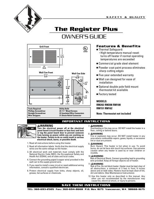
<strong>The</strong> <strong>Register</strong> <strong>Plus</strong><br />
OWNER’S <strong>GUIDE</strong><br />
5 7 /8"T<br />
14,92<br />
1"T<br />
2,54<br />
2"T<br />
5,08<br />
4"T<br />
10,16<br />
2"T<br />
5,08<br />
Dimensions in<br />
inches (cm) 1"T<br />
2,54<br />
2 1/2"T<br />
3<br />
6,35<br />
3/8"T 45˚T<br />
8,57<br />
Utility Knife<br />
(4) 1½“ Wood Screws<br />
(3) Insulated Wire Connectors<br />
(1) Strain Relief Connector<br />
WARNING<br />
Turn the electrical power off at the electrical<br />
panel board (circuit breaker or fuse box) and lock<br />
or tag the panel board door to prevent someone<br />
from turning on power while you are working on<br />
the heater. Failure to do so could result in serious<br />
electrical shock, burns, or possible death.<br />
1. Read all instructions before using this heater.<br />
2. Read all information labels. Verify that the electrical supply<br />
wires are the same voltage as the heater.<br />
3. All electrical work and materials must comply with the<br />
National Electric Code (NEC), the Occupational Safety and<br />
Health Act (OSHA), and all state and local codes.<br />
4. Connect the grounding pigtail (copper wire) provided in the<br />
wall can to the supply ground wire.<br />
5. If you need to install a new circuit or need additional wiring<br />
information, consult a qualified electrician.<br />
6. Protect electrical supply from kinks, sharp objects, oil,<br />
grease, hot surfaces or chemicals.<br />
T<br />
Wall Can Side<br />
3/4"T<br />
1,91<br />
Features & Benefits<br />
■ <strong>The</strong>rmal Safeguard:<br />
• High temperature manual reset:<br />
turns off heater if normal operating<br />
temperatures are exceeded<br />
■ Commercial grade steel element<br />
■ Powder coat paint process eliminates<br />
sharp cutting edges<br />
■ Five year extended warranty<br />
■ Wall can designed for ease of<br />
installation<br />
■ Optional double pole field mount<br />
thermostat kit available<br />
■ Factory tested<br />
MODELS:<br />
RM202 RM208 RM108<br />
RM151 RM162<br />
IMPORTANT INSTRUCTIONS<br />
SAVE THESE INSTRUCTIONS<br />
Note: <strong>The</strong>rmostat not included<br />
7. WARNING<br />
Overheating or fire may occur. DO NOT install the heater in a<br />
floor, ceiling or behind doors.<br />
8. WARNING<br />
Fire or explosion may occur. DO NOT install heater in any<br />
area where combustible vapors, gases, liquids, or excessive<br />
lint or dust are present.<br />
9. WARNING<br />
Burn Hazard. This heater is hot when in use. To avoid<br />
burns, do not let bare skin touch hot surfaces. Use extreme<br />
caution when any heater is used by or near children or<br />
invalids.<br />
10. WARNING<br />
Risk of Electrical Shock. Connect grounding lead to grounding<br />
wire provided. Keep all foreign objects out of heater.<br />
11. WARNING<br />
Risk of Fire. Do not block heater. Heater must be kept clear of<br />
all obstructions: a minimum of 3 feet in front, 6 inches<br />
above and on both sides. Heaters must be kept clean of lint,<br />
dirt and debris. (See Maintenance Instructions).<br />
12. Use this heater only as described in this manual. Any<br />
other use not recommended by the manufacturer may<br />
cause fire, electrical shock, or injury to persons.<br />
TEL: 360-693-2505 Fax: 360-694-8668 P.O. Box 1675 Vancouver, WA 98668-1675
READ ALL<br />
INSTRUCTIONS<br />
AND SAFETY<br />
INFORMATION<br />
IMPORTANT!<br />
It is extremely<br />
important you<br />
verify the<br />
electrical supply<br />
wires are the<br />
same voltage as<br />
the heater (i.e.<br />
120 volt heater to<br />
120 volt power<br />
supply and 240 volt<br />
heater to 240 volt<br />
power supply).<br />
If replacing an<br />
existing heater,<br />
check the labels<br />
of the old heater<br />
and replace using<br />
the same voltage.<br />
Hooking a 240 volt<br />
heater to a 120 volt<br />
power supply will<br />
drastically reduce<br />
the heater's<br />
output. Hooking a<br />
120 volt heater to a<br />
240 volt power<br />
supply will<br />
destroy the heater.<br />
Connecting your<br />
heater to an<br />
incompatible<br />
power supply will<br />
void the warranty.<br />
Warranty is void if<br />
any material is<br />
sprayed on the<br />
element or blower.<br />
Installation Instructions<br />
Part One<br />
PLACEMENT: For best results install <strong>The</strong> <strong>Register</strong> <strong>Plus</strong> on an inside wall. Headers and bracing are not<br />
necessary. NOTE: <strong>The</strong> wall can must be installed in the TOP UP (horizontal) position only. Heater is not<br />
approved for ceiling mount.<br />
THERMOSTAT: A thermostat is required. A <strong>Cadet</strong> Elec tronic <strong>The</strong>rmostat is recommended for ultimate control<br />
and comfort.<br />
How do I install for new construction?<br />
<strong>The</strong> RM series REQUIRES A MINIMUM distance<br />
of 6 inches from adjacent surfaces and 4½ inches<br />
from the floor. However, <strong>Cadet</strong> RECOMMENDS<br />
12 inches from all adjacent surfaces and 12 inches<br />
from the floor (See Figure 5) for longer and cleaner<br />
performance. Heaters must be spaced at least<br />
3 feet apart.<br />
Secure the wall can to the studs and/or sill plate<br />
with screws through the larger (<br />
FIGURE 1<br />
Metal legs position wall can<br />
at minimum floor clearance.<br />
3/16<br />
STEP 1 Mount Wall Can<br />
inch) holes.<br />
(See Figures 1 and 2).<br />
STEP 2 Route Supply Wires<br />
FIGURE 2<br />
Bend one leg<br />
90 degrees<br />
for higher<br />
placement<br />
and secure<br />
to studs.<br />
FIGURE 3<br />
Face of wall can must<br />
extend ½ inch or 5/8<br />
inch from face of stud<br />
to allow for thickness<br />
of sheetrock. Mount<br />
wall can flush with<br />
finished surface.<br />
Route supply wire from circuit breaker to<br />
thermo stat to wall can. Remove a knockout<br />
and attach the supply wire with a strain relief<br />
connector leaving 10 inches wire lead for later<br />
use. Connect supply ground wire to grounding<br />
pigtail in wall can (See Figure 4). Proceed to<br />
PART TWO.<br />
GROUNDING<br />
WIRE<br />
SUPPLY<br />
WIRE<br />
WIRE<br />
CONNECTOR<br />
GROUNDING<br />
PIGTAIL<br />
FIGURE 4<br />
KNOCK-OUT<br />
(TWIST TO<br />
REMOVE)<br />
STRAIN RELIEF<br />
CONNECTOR<br />
How do I install in an existing wall?<br />
STEP 1 Cut Hole In Wall<br />
Cut a hole 12¾ inches wide by 6 inches high<br />
next to wall stud. <strong>The</strong> RM series REQUIRES A<br />
MINIMUM distance of 6 inches from adjacent<br />
surfaces and 4½ inches from the floor. However,<br />
<strong>Cadet</strong> RECOMMENDS 12 inches from all adjacent<br />
surfaces and 12 inches from the floor (See<br />
Figure 5) for longer and cleaner performance.<br />
Heaters must be spaced at least 3 feet apart.<br />
FIGURE 5<br />
STEP 2 Route Supply Wires<br />
Route supply wire from circuit breaker to wall<br />
thermo stat, then to wall can. Remove a knockout<br />
and attach the supply wire with a strain relief<br />
connector leaving 10 inches wire lead for later<br />
use (See Figure 4). Connect sup ply ground wire<br />
to ground ing pigtail in wall can.<br />
STEP 3 Mount Wall Can<br />
FIGURE 6<br />
Insert wall can, legs<br />
first, into opening<br />
and rotate into wall.<br />
FIGURE 7<br />
Keeping front of<br />
wall can flush with<br />
finished surface,<br />
secure to wall stud<br />
with screws through<br />
larger ( 3/16 inch) holes.<br />
IMPORTANT: Insert two drywall screws into<br />
the small holes opposite the wall stud into the<br />
drywall to rest against backside of sheetrock<br />
(keeping wall can flush to wall).<br />
Proceed to PART TWO.
Installation Instructions<br />
Part Two<br />
STEP 1 If you are installing a Multi-Watt heater, model numbers RM151 or RM162, begin with STEP 2<br />
below. If you are installing an RM202, RM208, or RM108, begin with STEP 3 below.<br />
STEP 2 Element Wire Configuration (Multi-watt models RM151 or RM162 only)<br />
<strong>Cadet</strong>’s Multi-Watt RM heater offers a variety of heat output options. You must first determine the<br />
desired wattage and then configure the heating element wire connections. <strong>The</strong> heater is shipped from<br />
the factory configured for 1600 Watts (240V) or 1200 Watts (208V) for RM162, and 1500 Watts (120V) for<br />
RM151. If this is the wattage you desire, proceed to STEP 3.<br />
On models RM151 and RM162, mark the wiring diagram on the back of the heater with the wattage used<br />
for future reference.<br />
FIGURE 1 RM Wiring Table<br />
MODEL<br />
RM162<br />
RM162<br />
RM151<br />
VOLTAGE<br />
240V<br />
208V<br />
120V<br />
STEP 3 Install Heater Assembly<br />
Set the heater assembly (blower<br />
wheel first) into the left side of the<br />
wall can. Fasten at top with screw<br />
provided. Unlace heater lead wires.<br />
Connect the supply wires to the<br />
heater wires (See Figure 2). Keep<br />
all wires away from element<br />
connections when wires are pushed<br />
into free space on right of heater.<br />
STEP 4 Install Grill<br />
Secure grill with the screws<br />
provided. Turn power on at the<br />
electrical panel board.<br />
IF YOUR DESIRED<br />
WATTAGE IS:<br />
1600<br />
900<br />
700<br />
1200<br />
675<br />
528<br />
1500<br />
1000<br />
500<br />
MANUAL RESET<br />
HIGH TEMP CUTOFF<br />
YOUR WIRES WILL BE CONFIGURED LIKE THIS:<br />
Upper Element A Lower Element C<br />
900W-240V 700W-240V<br />
Yellow Terminal X Blue Terminal Z<br />
Yellow Terminal X None (*)<br />
None (*) Yellow Terminal X<br />
675W-208V 525W-208V<br />
Yellow Terminal X Blue Terminal Z<br />
Yellow Terminal X None (*)<br />
None (*) Yellow Terminal X<br />
1000W-120V 500W-120V<br />
Fasten screw<br />
Manual reset button<br />
Yellow Terminal X<br />
Yellow Terminal X<br />
None (*)<br />
*Cut Blue Terminal from Red Wire and wrap with electrical tape.<br />
Yellow Terminal Y remains connected at B . Do Not Touch.<br />
Blower wheel<br />
Heater leads<br />
Blue Terminal Z<br />
None (*)<br />
Yellow Terminal X<br />
675W-208V<br />
900W-240V<br />
1000W-120V<br />
Motor End View<br />
Heater Element Locations<br />
Supply leads<br />
FIGURE 2<br />
Grounding<br />
Pigtail<br />
525W-208V<br />
700W-240V<br />
500W-120V<br />
WARNING<br />
Risk of Electrical<br />
Shock. Connect<br />
grounding lead to<br />
grounding wire<br />
provided. Keep all<br />
foreign objects out<br />
of heater.<br />
WARNING<br />
Risk of Fire.<br />
Heater must be<br />
kept clear of all<br />
obstructions: a<br />
minimum of 3 feet<br />
in front; 6 inches<br />
on both sides and<br />
above. Heaters<br />
must be kept clean<br />
of lint, dirt and<br />
debris.<br />
WARNING<br />
Turn the electrical<br />
power off at the<br />
electrical panel<br />
board (circuit<br />
breaker or fuse<br />
box) and lock or<br />
tag the panel board<br />
door to prevent<br />
someone from<br />
turning on power<br />
while you are<br />
working on the<br />
heater. Failure to<br />
do so could result<br />
in serious electrical<br />
shock, burns,<br />
or possible death.
How to operate your heater<br />
1. Once installation is complete and power has been restored, turn the<br />
thermostat knob fully clockwise.<br />
2. When the room reaches your comfort level, turn the thermostat knob<br />
counterclockwise until the heater turns off. <strong>The</strong> heater will automatically<br />
cycle around this preset temperature.<br />
3. To reduce the room temperature, turn the knob counterclockwise.<br />
To increase the room temperature, turn the knob clockwise.<br />
Maintenance As needed, or every six months, minimum.<br />
1. WARNING! Before removing grill, turn the electrical power off at the<br />
electrical panel board (circuit breaker or fuse box). Lock or tag the panel<br />
board door to prevent someone from accidentally turning the power<br />
on while you are working on the heater. Failure to do so could result<br />
in serious electrical shock, burns, or possible death.<br />
2. It is important that you verify power has been turned off and no power is going<br />
to the heater before proceeding. Circuit breakers are often not marked correctly<br />
and turning the wrong breaker off could mean electricity is flowing to the heater,<br />
even if the heater does not appear to be working. If you are uncomfortable<br />
working with electrical appliances, unable to follow these guidelines,<br />
or do not have the necessary equipment, consult a qualified electrician.<br />
3. Once you verify the power has been turned off correctly, proceed to the<br />
next step.<br />
Heater discharges smoke<br />
or emits a burnt odor.<br />
Element heats for a moment<br />
without the fan turning, then<br />
immediately stops heating.<br />
Heater does not run.<br />
Heater continually trips the<br />
manual reset temperature<br />
limit control.<br />
Operation & Maintenance<br />
4. Defective circuit breaker.<br />
1. Insufficient element temperature.<br />
2. Incorrect supply voltage.<br />
3. Element has failed.<br />
1. Heat loss from room is greater than heater capacity.<br />
2. Defective thermostat.<br />
3. <strong>The</strong>rmostat wired incorrectly to heater.<br />
1. Dust, lint or other matter has accumulated<br />
inside heater.<br />
1. Defective motor or internal connection.<br />
2. Fan or motor jammed.<br />
1. <strong>The</strong>rmostat set too low.<br />
2. Heater has tripped the manual reset temperature<br />
limit control.<br />
3. Power not on at the circuit breaker.<br />
4. Broken or poorly connected wire(s) to heater.<br />
5. Defective thermostat.<br />
1. Dust, lint or other matter has accumulated<br />
inside heater.<br />
2. Airflow is blocked.<br />
3. Fan or motor is jammed.<br />
4. None of the above.<br />
Troubleshooting Chart<br />
Warranty<br />
4. Remove screws and take off grill.<br />
5. Wash grill with hot soapy water and dry immediately.<br />
6. While holding blower wheel (to avoid damage or bending), use a hair<br />
dryer or vacuum on blow cycle to blow debris through the element<br />
(Do not touch element).<br />
7. Vacuum blower area without touching the elements.<br />
8. Replace grill and secure with screws.<br />
9. Turn thermostat to desired setting.<br />
10. Turn power back on at the electrical panel board.<br />
About the Manual Reset Temperature Limit Control<br />
<strong>The</strong> heater is protected by a temperature-limiting control. <strong>The</strong> manual reset<br />
temperature limit control is designed to open the heater circuit when excessive<br />
operating temperatures are detected. <strong>The</strong> problem must be assessed and<br />
the limit must be reset to resume operation.<br />
Resetting the Manual Reset Temperature Limit Control<br />
If the manual-reset limit control has opened the heater circuit due to excessive<br />
operating temperatures, the heater will not work until the manual reset limit<br />
button is pressed. After allowing the unit to cool for at least 10 minutes and<br />
resolving the problem causing the limit to trip; use a narrow object such as<br />
a ball-point pen to access the manual reset button through the lower-right<br />
center section of the heater grill. Press FIRMLY and be sure to listen and feel<br />
for a click, indicating it has been reset.<br />
CONSULT LOCAL ELECTRICAL CODES TO DETERMINE WHAT WORK MUST BE PERFORMED BY QUALIFIED ELECTRICAL SERVICE PERSONNEL<br />
Symptom Problem Solution<br />
Breaker trips immediately 1. Incorrect supply voltage.<br />
1. Verify that supply voltage matches the heater rating.<br />
upon energizing heater. 2. Overloaded circuit.<br />
2. <strong>The</strong> total amperage of all heaters on a branch circuit must not be more than 80% of the<br />
amperage rating of the circuit breaker and supply wire ratings. Use a lower wattage heater,<br />
or reduce the number of heaters on the circuit.<br />
3. A short circuit exists in the supply or heater wiring. 3. Shorted supply or heater wires may be accompanied by severe sparking. Inspect all supply<br />
and heater wiring insulation for damage. Do not reset the circuit breaker until all electrical<br />
shorts have been repaired.<br />
4. Replace the circuit breaker.<br />
Heater fan operates, but<br />
1. Allow a few moments for element to reach operating temperature.<br />
does not discharge warm air.<br />
2. Verify that supply voltage matches the heater rating.<br />
3. Replace element.<br />
Heater will not shut off.<br />
1. Close doors and windows. Provide additional insulation or install a higher-wattage heater<br />
or multiple heaters if necessary (if your circuit is rated for more capacity).<br />
2. Adjust thermostat to its lowest setting. If heater continues to run (allow two minutes for the<br />
thermostat to respond), and room temperature is greater than 50 degrees; replace thermostat.<br />
3. Refer to thermostat documentation and correct wiring.<br />
1. Clean heater (see “Operation & Maintenance” section for instructions).<br />
Maintenance: For more effective and safer operation and to prolong the life of the heater, read<br />
the Owner’s Guide and follow the maintenance instructions included with each heater.<br />
Failure to properly maintain the heater will void any warranty and may cause the heater to<br />
function improperly. Warranties are non transferable and apply to original consumer only.<br />
Warranty terms are set out below.<br />
LIMITED ONE-YEAR WARRANTY: <strong>Cadet</strong> will repair or replace any <strong>Cadet</strong> product, including<br />
thermostats, found to be defective within one year after the date of purchase.<br />
Extended Product Warranty<br />
LIMITED FIVE-YEAR WARRANTY: <strong>Cadet</strong> will repair or replace any <strong>Register</strong> <strong>Plus</strong> (RM)<br />
series element or motor found to be defective or malfunctioning from first date of purchase<br />
through the fifth year.<br />
THESE WARRANTIES DO NOT APPLY:<br />
1. Damage occurs to the product through improper installation or incorrect supply voltage;<br />
2. Damage occurs to the product through improper maintenance, misuse, abuse, accident,<br />
or alteration;<br />
3. <strong>The</strong> product is serviced by anyone other than <strong>Cadet</strong>.<br />
4. If the date of manufacture of the product cannot be determined;<br />
5. If the product is damaged during shipping through no fault of <strong>Cadet</strong>.<br />
6. CADET’S WARRANTY IS LIMITED TO REPAIR OR REPLACEMENT AS SET OUT HEREIN.<br />
CADET SHALL NOT BE LIABLE FOR DAMAGES SUCH AS PROPERTY DAMAGE OR FOR<br />
CONSEQUENTIAL DAMAGES AND/OR INCIDENTAL EXPENSES RESULTING FROM<br />
BREACH OF THESE WRITTEN WARRANTIES OR ANY EXPRESS OR IMPLIED WARRANTY.<br />
1. Heater or fan motor requires replacement.<br />
2. Remove obstruction, and press heater manual reset button (see “Operation & Maintenance”<br />
section for instructions).<br />
1. Adjust thermostat to a higher temperature until heater operates (see Problem #6 if the<br />
problem persists).<br />
2. Press the manual reset button (see “Operation & Maintenance” section for instructions).<br />
3. Turn on the correct circuit breaker in the main panel.<br />
4. Turn off power at circuit breaker. Check supply wire continuity and proper connection<br />
to heater wires.<br />
5. <strong>The</strong> entire heater, or any of its components may be checked for continuity to determine<br />
the cause of any problem. Repair or replace the heater.<br />
1. Clean heater (see “Operation & Maintenance” section for instructions.)<br />
2. Remove obstruction. Maintain a minimum distance of 6 inches from adjacent surfaces, 4.5 inches<br />
from the floor, and 3 feet for furniture or other objects placed directly in front of the heater.<br />
3. Remove obstruction, and press heater manual reset button (see “Operation & Maintenance”<br />
section for instructions).<br />
4. Replace heater assembly .<br />
7. IN THE EVENT CADET ELECTS TO REPLACE ANY PART OF YOUR CADET PRODUCT, THE<br />
REPLACEMENT PARTS ARE SUBJECT TO THE SAME WARRANTIES AS THE PRODUCT.<br />
THE INSTALLATION OF REPLACEMENT PARTS DOES NOT MODIFY OR EXTEND THE<br />
UNDERLYING WARRANTIES. REPLACEMENT OR REPAIR OF ANY CADET PRODUCT OR<br />
PART DOES NOT CREATE ANY NEW WARRANTIES.<br />
8. <strong>The</strong>se warranties give you specific legal rights, and you may also have other rights<br />
which vary from state to state. <strong>Cadet</strong> neither assumes, nor authorizes anyone to<br />
assume for it, any other obligation or liability in connection with its products other than<br />
as set out herein.<br />
If you believe your <strong>Cadet</strong> product is defective, please contact <strong>Cadet</strong> <strong>Manufacturing</strong> Co. at<br />
360-693-2505, during the warranty period, for instructions on how to have the repair or<br />
replacement processed. Warranty claims made after the warranty period has expired will<br />
be denied. Products returned without authorization will be refused.<br />
Parts and Service<br />
Visit http://support.cadetco.com for information on where to obtain parts and service.<br />
Reduce-Reuse-Recycle<br />
This product is made primarily of recyclable materials. You can reduce<br />
your carbon footprint by recycling this product at the end of its useful life.<br />
Contact your local recycling support center for further recycling instructions.<br />
©2009 <strong>Cadet</strong> <strong>Manufacturing</strong> Co. Printed in U.S.A. Rev. 6/09 #720104
Parte delantera de la rejilla<br />
Parte delantera de la cámara de pared<br />
Herramientas necesarias:<br />
Destornillador Phillips<br />
Destornillador plano<br />
Pelacables<br />
<strong>The</strong> <strong>Register</strong> <strong>Plus</strong><br />
GUÍA PARA EL PROPIETARIO<br />
5 7 /8"T<br />
14,92<br />
1"T<br />
2,54<br />
2"T<br />
5,08<br />
Lado de la cámara<br />
de pared<br />
T<br />
4"T<br />
10,16<br />
2"T<br />
5,08<br />
3/4"T<br />
1,91<br />
Dimensions in<br />
inches (cm) 1"T<br />
2,54<br />
2 1/2"T<br />
3<br />
6,35<br />
3/8"T 45˚T<br />
8,57<br />
Cuchillo multiuso<br />
(4) tornillos de 1½” para madera<br />
(3) conectores de alambre aislados<br />
(1) conector de alivio de tensión<br />
Características y<br />
Beneficios<br />
■ Protección térmica:<br />
• Reglaje manual de alta temperatura:<br />
apaga el calentador si se sobrepasan<br />
las temperaturas de operación normales<br />
■ Elemento de acero de calidad comercial<br />
■ Proceso de pintado con cobertura<br />
pulverizada que elimina los bordes<br />
filosos cortantes<br />
■ Garantía extendida de cinco años<br />
■ Cámara de pared diseñada para<br />
facilitar la instalación<br />
■ Se ofrece juego de termostato opcional<br />
de doble polo para montaje en terreno<br />
■ Probado en fábrica<br />
MODELOS:<br />
RM202 RM208 RM108<br />
RM151 RM162<br />
ADVERTENCIA<br />
Nota: Termostato no incluido<br />
INSTRUCCIONES IMPORTANTES<br />
7. ADVERTENCIA<br />
Desconecte la electricidad en el tablero del Podría producirse sobrecalentamiento o un incendio. NO<br />
panel eléctrico (caja de cortacircuitos o fusibles) instale el calentador en el suelo, cielo raso o detrás de puertas.<br />
y trabe o coloque un cartel en la puerta del<br />
tablero del panel para evitar que alguien vuelva a<br />
conectar la energía mientras se esté trabajando en el<br />
calentador. De lo contrario podrían producirse graves<br />
golpes eléctricos, quemaduras e incluso la muerte.<br />
1. Lea todas las instrucciones antes de usar este calentador.<br />
2. Lea todas las etiquetas que contengan información.<br />
Verifique que todos los cables de suministro eléctrico<br />
sean del mismo voltaje que el calentador.<br />
8. ADVERTENCIA<br />
Podrían producirse explosiones o incendios. NO instale el<br />
calentador en áreas donde exista la presencia de vapores,<br />
gases o líquidos combustibles o exceso de pelusas o polvo.<br />
9. ADVERTENCIA<br />
Riesgo de quemaduras. Este calentador se calienta mucho<br />
cuando está en uso. Para evitar quemaduras, no lo toque con<br />
su piel descubierta. Tenga mucho cuidado al utilizar cualquier<br />
tipo de calentador en presencia de niños o personas inválidas.<br />
3. Todo trabajo y materiales eléctricos deben cumplir con<br />
el Código Eléctrico Nacional (“NEC”, por su sigla en<br />
inglés), con la Ley de Seguridad y Salud Ocupacional<br />
(“OSHA”, por su sigla en inglés) y con todos los códigos<br />
estatales y locales.<br />
10. ADVERTENCIA<br />
Riesgo de electrocución. Conecte el conductor a tierra al<br />
cable de puesta a tierra provisto. Evite que entren objetos<br />
extraños al calentador.<br />
4. Conecte el cable en espiral (de cobre) de puesta a tierra<br />
que viene en la cámara de pared al cable de conexión a<br />
tierra de suministro.<br />
5. Si se debe instalar un nuevo circuito o se necesita<br />
información adicional sobre el cableado, consulte a un<br />
electricista calificado.<br />
11. ADVERTENCIA<br />
Riesgo de incendio. No bloquee el calentador. El calentador<br />
debe mantenerse sin obstrucciones: un mínimo de 3 pies<br />
por delante, 6 pulgadas por encima y en cada costado.<br />
Los calentadores deben mantenerse sin pelusas, suciedad<br />
ni residuos. (Consulte las instrucciones de mantenimiento).<br />
6. Evite que los cables de suministro eléctrico se retuerzan o 12. Use este calentador sólo como se describe en este manual.<br />
entren en contacto con objetos afilados, aceite, grasa, Todo otro uso no recomendado por el fabricante puede<br />
superficies calientes o sustancias químicas.<br />
causar incendios, descargas eléctricas o lesiones personales.<br />
CONSERVE ESTAS INSTRUCCIONES<br />
TEL: 360-693-2505 Fax: 360-694-8668 P.O. Box 1675 Vancouver, WA 98668-1675
LEA TODAS LAS<br />
INSTRUCCIONES<br />
E INFORMACIÓN<br />
ACERCA DE LA<br />
SEGURIDAD<br />
¡IMPORTANTE!<br />
Es extremadamente<br />
importante verificar<br />
que los cables de<br />
suministro eléctrico<br />
sean del mismo<br />
voltaje que el<br />
calentador (es decir,<br />
un calentador de<br />
120 voltios con un<br />
suministro de energía<br />
de 120 voltios y un<br />
calentador de 240<br />
voltios con un<br />
suministro de energía<br />
de 240 voltios). Si va<br />
a reemplazar un<br />
calentador existente,<br />
revise las etiquetas<br />
del calentador<br />
antiguo y sustitúyalo<br />
por otro del mismo<br />
voltaje. Si se conecta<br />
un calentador de<br />
240 voltios a un<br />
suministro de energía<br />
de 120 voltios,<br />
se reducirá<br />
drásticamente el<br />
rendimiento del<br />
calentador. Si se<br />
conecta un<br />
calentador de<br />
120 voltios a un<br />
suministro de energía<br />
de 240 voltios,<br />
se destruirá el<br />
calentador. Si se<br />
conecta el calentador<br />
a un suministro de<br />
energía incompatible,<br />
se anulará la<br />
garantía.<br />
La garantía pierde<br />
su validez si se rocía<br />
algún producto en el<br />
elemento o en el<br />
soplador.<br />
Instrucciones para la instalación<br />
Parte Uno<br />
UBICACIÓN: Para obtener mejores resultados, instale el calentador <strong>Register</strong> <strong>Plus</strong> en una pared interior. No<br />
se necesitan brochales ni soportes. NOTA: La cámara de pared debe instalarse sólo con la parte superior<br />
hacia arriba (posición horizontal). No se ha aprobado el uso del calentador para montaje en cielo raso.<br />
TERMOSTATO: Se requiere un termostato. Se recomienda usar un termostato electrónico <strong>Cadet</strong> para una<br />
comodidad y un control óptimos.<br />
¿Cómo se instala el calentador en una<br />
¿Cómo se instala el calentador en una<br />
construcción nueva?<br />
pared existente?<br />
PASO 1 Montaje de la cámara de pared PASO 1 Corte un orificio en la pared<br />
La serie RM REQUIERE una distancia mínima de<br />
6 pulgadas de las superficies adyacentes y 4½<br />
pulgadas desde el piso. Sin embargo, <strong>Cadet</strong><br />
RECOMIENDA 12 pulgadas de distancia de todas<br />
las superficies adyacentes y 12 pulgadas del piso<br />
(vea la figura 5) para una vida útil más larga y un<br />
funcionamiento más limpio. Si se instalan varios<br />
calentadores, deje al menos tres pies entre ellos.<br />
Fije la cámara de pared a los puntales y/o el larguero<br />
mediante tornillos a través de los orificios más<br />
grandes (3 /16 de pulgada). (Consulte las figuras 1 y 2).<br />
FIGURA 1<br />
Las patas metálicas posicionan<br />
la cámara de pared de modo<br />
que quede el espacio mínimo<br />
entre ésta y el piso.<br />
FIGURA 2<br />
Doble una pata<br />
en 90 grados<br />
para una<br />
instalación a<br />
mayor altura<br />
y fíjela a los<br />
puntales.<br />
FIGURA 3<br />
La superficie de la cámara<br />
de pared debe sobresalir<br />
entre 1/2 pulgada y 5/8 de<br />
pulgada de la superficie del<br />
puntal a fin de dejar espacio<br />
para la lámina de yeso. Monte<br />
la cámara de pared a ras<br />
con la superficie acabada.<br />
PASO 2 Instalación de los cables<br />
de suministro<br />
Dirija el cable de suministro desde el cortacircuito<br />
al termostato y a la cámara de pared. Quite un<br />
destapadero y coloque el cable de suministro<br />
mediante un conector de alivio de tensión dejando<br />
10 pulgadas de cable de conexión para utilizarlo<br />
más adelante. Conecte el alambre de suministro a<br />
tierra al cable espiral de puesta a tierra situado en<br />
la cámara de pared (consulte la figura 4). Continúe<br />
con la PARTE DOS.<br />
FIGURA 4<br />
Corte un orificio de 12¾ pulgadas de ancho por 6<br />
de alto al lado del puntal de la pared. La serie RM<br />
REQUIERE una distancia mínima de 6 pulgadas de<br />
las superficies adyacentes y 4½ pulgadas del piso.<br />
Sin embargo, <strong>Cadet</strong> RECOMIENDA 12 pulgadas de<br />
distancia de todas las superficies adyacentes y 12<br />
pulgadas del piso (vea la figura 5) para una vida útil<br />
más larga y un funcionamiento más limpio. Si se<br />
instalan varios calentadores, deje al menos tres<br />
pies entre ellos.<br />
FIGURA 5<br />
PASO 2<br />
Instalación de los cables<br />
de suministro<br />
Dirija el cable de suministro desde el cortacircuito<br />
al termostato mural y luego a la cámara de pared.<br />
Quite un destapadero y fije el cable de suministro<br />
mediante un conector de alivio de tensión dejando<br />
10 pulgadas de cable de conexión para utilizarlo<br />
más adelante (consulte la figura 4). Conecte el cable<br />
de puesta a tierra de suministro al cable en espiral<br />
de conexión a tierra situado en la cámara de pared.<br />
PASO 3 Montaje de la cámara de pared<br />
FIGURA 6<br />
Inserte la cámara de<br />
pared, con las patas<br />
por delante, en la<br />
abertura y gírela<br />
para introducirla<br />
en la pared.<br />
FIGURA 7<br />
Manteniendo la parte<br />
delantera de la<br />
cámara al ras con la<br />
superficie acabada,<br />
fije la cámara al<br />
puntal con 2 tornillos<br />
a través de los cuatro<br />
orificios grandes (de<br />
3/16 de pulgada).<br />
IMPORTANTE: Coloque dos tornillos para paredes<br />
de yeso en los orificios pequeños en frente del<br />
puntal de la pared de yeso a fin de apoyar el<br />
calentador en la parte posterior de la lámina<br />
(manteniendo la cámara al ras con la pared).<br />
Continúe con la PARTE DOS.
Instrucciones para la instalación<br />
Parte Dos<br />
PASO 1 Si va a instalar un calentador de vatiaje múltiple, números de modelo RM151 o RM162,<br />
comience por el PASO 2 a continuación. Si va a instalar un RM202, RM208 o RM108, comience por el<br />
PASO 3 a continuación.<br />
PASO 2 Configuración de alambres del elemento (sólo modelos de vatiaje múltiple RM151 o RM162)<br />
El calentador <strong>Cadet</strong> RM de vatiaje múltiple ofrece una gran variedad de opciones de generación de<br />
calor. Primero debe determinar el vatiaje deseado y luego configurar las conexiones de alambres del<br />
elemento calentador. El calentador viene configurado de fábrica para 1600 vatios (240 V) o 1200 vatios<br />
(208 V) en el caso del modelo RM162, y 1500 vatios (120 V) en el caso del RM151. Si éste es el vatiaje que<br />
desea, proceda con el PASO 3.<br />
Como referencia futura para los modelos RM151 y RM162, anote el vatiaje utilizado en el diagrama de<br />
cableado situado en la parte posterior del calentador.<br />
FIGURA 1 Tabla de cableado del modelo RM<br />
MODELO<br />
RM162<br />
RM162<br />
RM151<br />
VOLTAJE<br />
240V<br />
208V<br />
120V<br />
PASO 4 Instale la rejilla<br />
Fije la rejilla con los tornillos suministrados.<br />
Conecte la alimentación<br />
en el tablero del panel eléctrico.<br />
SI EL VATIAJE QUE<br />
DESEA ES:<br />
1600<br />
900<br />
700<br />
1200<br />
675<br />
528<br />
1500<br />
1000<br />
500<br />
LOS ALAMBRES SE DEBEN CONFIGURAR ASÍ:<br />
Elemento superior A Elemento inferior C<br />
900W-240V 700W-240V<br />
Terminal amarillo X Terminal azul Z<br />
Terminal amarillo X Ninguno (*)<br />
Ninguno (*) Terminal amarillo X<br />
675W-208V 525W-208V<br />
Terminal amarillo X Terminal azul Z<br />
Terminal amarillo X Ninguno (*)<br />
Ninguno (*) Terminal amarillo X<br />
1000W-120V 500W-120V<br />
Terminal amarillo X<br />
Terminal amarillo X<br />
Ninguno (*)<br />
*Corte el terminal azul del alambre rojo y cúbralo con cinta para uso eléctrico.<br />
El terminal Y permanece conectado a B . No lo toque.<br />
PASO 3 Instale la unidad del calentador<br />
Instale el conjunto del calentador<br />
(rueda del soplador primero) en el<br />
costado izquierdo de la cámara de<br />
pared. Afiáncelo en la parte superior<br />
con el tornillo que se proporciona.<br />
Desamarre los alambres conductores<br />
del calentador. Conecte los alambres<br />
de suministro con los del calentador<br />
(consulte la figura 2). Mantenga todos<br />
los alambres lejos de las conexiones<br />
del elemento al introducirlos<br />
en el espacio libre a la derecha<br />
del calentador.<br />
Apriete el tornillo<br />
Rueda del soplador<br />
Botón de reglaje manual<br />
Conductores<br />
del calentador<br />
Terminal azul Z<br />
Ninguno (*)<br />
Terminal amarillo X<br />
675W-208V<br />
900W-240V<br />
1000W-120V<br />
Vista extrema del motor,<br />
ubicaciones del<br />
elemento calentador<br />
Conductores<br />
de suministro<br />
525W-208V<br />
700W-240V<br />
500W-120V<br />
FIGURA 2<br />
Cable en espiral<br />
de puesta a tierra<br />
ADVERTENCIA<br />
Riesgo de<br />
electrocución.<br />
Conecte el<br />
conductor a tierra<br />
al cable de puesta<br />
a tierra provisto.<br />
Evite que entren<br />
objetos extraños<br />
al calentador.<br />
ADVERTENCIA<br />
Riesgo de incendio.<br />
El calentador debe<br />
mantenerse sin<br />
obstrucciones: un<br />
mínimo de 3 pies por<br />
delante, 6 pulgadas<br />
en cada costado y<br />
por encima. Los<br />
calentadores deben<br />
mantenerse sin<br />
pelusas, suciedad<br />
ni residuos.<br />
ADVERTENCIA<br />
Desconecte la<br />
electricidad en el<br />
tablero del panel<br />
eléctrico (caja de<br />
cortacircuitos o<br />
fusibles) y trabe o<br />
coloque un cartel en<br />
la puerta del tablero<br />
del panel para evitar<br />
que alguien vuelva<br />
a conectar la<br />
energía mientras<br />
se esté trabajando<br />
en el calentador. De<br />
lo contrario podrían<br />
producirse graves<br />
golpes eléctricos,<br />
quemaduras e<br />
incluso la muerte.
Funcionamiento y mantenimiento<br />
Cómo hacer funcionar el calentador<br />
1. Una vez que se haya realizado la instalación y reestablecido la energía<br />
eléctrica, gire totalmente la perilla del termostato en el sentido de las<br />
manecillas del reloj.<br />
2. Cuando la habitación haya alcanzado un nivel cómodo, gire la perilla del<br />
termostato en sentido contrario a las manecillas del reloj hasta que el<br />
calentador se apague. El calentador se encenderá y apagará automáticamente<br />
según esta temperatura preestablecida.<br />
3. Para reducir la temperatura del ambiente, gire la perilla en sentido<br />
contrario a las manecillas del reloj. Para aumentar la temperatura del<br />
ambiente, gire la perilla en el sentido de las manecillas del reloj.<br />
Mantenimiento Según sea necesario, o cada seis meses como mínimo.<br />
1. ¡ADVERTENCIA! Antes de quitar la rejilla, desconecte la electricidad<br />
en el tablero del panel eléctrico (cortacircuito o caja de fusibles). Trabe<br />
o coloque un cartel en la puerta del tablero del panel para evitar que<br />
alguien conecte accidentalmente la energía mientras se esté trabajando<br />
en el calentador. De lo contrario podrían producirse graves golpes<br />
eléctricos, quemaduras e incluso la muerte.<br />
2. Antes de proceder, es importante que usted verifique que se haya desconectado<br />
la alimentación y que el calentador no reciba energía. Los cortacircuitos no<br />
suelen estar correctamente marcados, y apagar el incorrecto podría significar<br />
que sigue fluyendo electricidad al calentador, aun cuando éste parezca no estar<br />
funcionando. Si no se siente cómodo al trabajar con artefactos eléctricos,<br />
no está en condiciones de acatar estas pautas o no cuenta con los equipos<br />
necesarios, solicite los servicios de un técnico electricista calificado.<br />
Garantía<br />
3. Una vez que verifique que se ha apagado la alimentación correctamente,<br />
prosiga con el paso siguiente.<br />
4. Retire los tornillos y extraiga la rejilla.<br />
5. Lave la rejilla con agua caliente y jabón, y séquela de inmediato.<br />
6. Mientras sujeta la rueda del soplador (para evitar que se dañe o tuerza),<br />
utilice una secadora o una aspiradora en el ciclo de soplado para quitar<br />
la suciedad en el elemento superior (sin tocarlo).<br />
7. Aspire el área del soplador sin tocar los elementos.<br />
8. Vuelva a instalar la rejilla y fíjela con los tornillos.<br />
9. Coloque el termostato en la graduación deseada.<br />
10. Vuelva a conectar la alimentación en el tablero del panel eléctrico.<br />
Acerca del control de límite de temperatura de reglaje manual<br />
El calentador está protegido por un control limitador de temperatura con reglaje<br />
manual, el cual está diseñado para abrir el circuito del calentador cuando se<br />
detectan temperaturas de funcionamiento excesivas. El problema debe evaluarse<br />
y el límite debe restablecerse para que el calentador vuelva a funcionar.<br />
Cómo restablecer el control limitador de temperatura de reglaje manual<br />
Si el control limitador de reglaje manual ha abierto el circuito del calentador<br />
debido a temperaturas de funcionamiento excesivas, el calentador no funcionará<br />
sino hasta que se oprima el botón de límite de reglaje manual. Después de dejar<br />
que la unidad se enfríe durante unos 10 minutos y resolver el problema que<br />
causa que se disyunte el interruptor de límite, utilice un objeto puntiagudo como<br />
un bolígrafo para acceder al botón de reglaje manual a través de la sección<br />
central inferior derecha de la rejilla del calentador. Oprima el botón FIRMEMENTE<br />
y asegúrese de escuchar y sentir un chasquido indicando que se ha restablecido.<br />
CONSULTE LOS CÓDIGOS ELÉCTRICOS LOCALES PARA DETERMINAR QUÉ TRABAJOS DEBEN SER REALIZADOS POR PERSONAL DE SERVICIO ELÉCTRICO CALIFICADO<br />
SÍNTOMA PROBLEMA SOLUCIÓN<br />
El interruptor se disyunta<br />
inmediatamente al<br />
encenderse el calentador.<br />
El ventilador del calentador<br />
funciona pero no envía<br />
aire caliente.<br />
El calentador no se apaga.<br />
El calentador emite humo<br />
o un olor a quemado.<br />
El elemento calienta por un<br />
momento sin que gire el ventilador<br />
y luego deja de calentar.<br />
El calentador no funciona.<br />
El calentador disyunta<br />
continuamente el control<br />
limitador de temperatura<br />
de reglaje manual.<br />
Tabla de resolución de problemas<br />
1.Voltaje de suministro incorrecto.<br />
2. Circuito sobrecargado.<br />
3. Hay un cortocircuito en los cables de suministro<br />
o del calentador.<br />
4. Cortacircuito defectuoso.<br />
1. Temperatura insuficiente del elemento.<br />
2. Voltaje de suministro incorrecto.<br />
3. El elemento ha fallado.<br />
1. La fuga de calor de la habitación es superior a la<br />
capacidad del calentador.<br />
2. Termostato defectuoso.<br />
3. Termostato cableado al calentador de forma incorrecta.<br />
1. Se han acumulado polvo, pelusas u otros<br />
materiales dentro del calentador.<br />
1. Motor o conexión interna defectuosos.<br />
2. Ventilador o motor trabado.<br />
1. El termostato se ha graduado muy bajo.<br />
2. El calentador ha disyuntado el control limitador<br />
de temperatura de reglaje manual.<br />
3. La energía no está conectada en el cortacircuito.<br />
4. El o los cables que van al calentador están rotos<br />
o mal conectados.<br />
5. Termostato defectuoso.<br />
1. Se han acumulado polvo, pelusas u otros<br />
materiales dentro del calentador.<br />
2. El flujo de aire está bloqueado.<br />
3. El ventilador o el motor está trabado.<br />
4. Ninguna de las anteriores.<br />
Mantenimiento: Para lograr una operación más eficaz y segura y prolongar la vida útil del<br />
calentador, lea la Guía del propietario y siga las instrucciones de mantenimiento incluidas con<br />
cada unidad. Si no le da el mantenimiento adecuado al calentador invalidará la garantía y<br />
puede hacer que el aparato funcione incorrectamente. Las garantías no son transferibles y<br />
rigen sólo para el comprador original. Los términos de la garantía se indican a continuación.<br />
GARANTÍA LIMITADA DE UN AÑO: <strong>Cadet</strong> reparará o reemplazará todo producto <strong>Cadet</strong>,<br />
incluyendo los termostatos, que presente averías en un plazo de un año a partir de la fecha<br />
de compra.<br />
Garantía extendida del producto<br />
GARANTÍA LIMITADA DE CINCO AÑOS: <strong>Cadet</strong> reparará o reemplazará, durante tres años<br />
a partir de la fecha de compra, todo elemento o motor serie <strong>Register</strong> <strong>Plus</strong> (RM) que se<br />
determine que está averiado o funcionando mal.<br />
ESTAS GARANTÍAS NO SON PERTINENTES PARA:<br />
1. Daños que sufra el producto por instalación o voltaje de suministro incorrectos;<br />
2. Daños que sufra el producto por mantenimiento incorrecto, uso indebido, abuso, accidente<br />
o alteraciones;<br />
3. Servicio que se le haya dado al producto por parte de personas o entidades ajenas a <strong>Cadet</strong>.<br />
4. Casos en que no se pueda determinar la fecha de fabricación del producto;<br />
5. Casos en que el producto resulte dañado durante el embarque por causas ajenas a <strong>Cadet</strong>.<br />
6. LA GARANTÍA DE CADET SE LIMITA A LA REPARACIÓN O REEMPLAZO, TAL COMO SE<br />
ESTABLECE EN ESTE DOCUMENTO. CADET NO SE HARÁ RESPONSABLE POR DAÑOS A<br />
LA PROPIEDAD O DAÑOS CONSECUENTES, COMO TAMPOCO POR GASTOS ACCIDEN-<br />
TALES DEBIDO AL INCUMPLIMIENTO DE ESTAS GARANTÍAS ESCRITAS O DE<br />
CUALQUIER GARANTÍA EXPRESA O IMPLÍCITA.<br />
1. Compruebe que el voltaje de suministro coincida con la calificación del calentador.<br />
2. El amperaje total de todos los calentadores en un circuito de rama no debe sobrepasar el 80%<br />
de la calificación de amperaje del cortacircuito y de las calificaciones de los cables de suministro.<br />
Utilice un calentador de vatiaje inferior o reduzca la cantidad de calentadores en el circuito.<br />
3. Los cables de suministro o del calentador que presentan cortocircuitos pueden ocasionar<br />
chispas peligrosas. Revise el aislamiento de todos los cables de suministro y del calentador<br />
para comprobar que no estén dañados. No reestablezca el cortacircuito sino hasta que se<br />
hayan reparado todos los cortocircuitos eléctricos.<br />
4. Reemplace el cortacircuito.<br />
1. Espere unos momentos para que el elemento alcance la temperatura de funcionamiento.<br />
2. Compruebe que el voltaje de suministro coincida con la calificación del calentador.<br />
3. Reemplace el elemento.<br />
1. Cierre las puertas y ventanas. Coloque aislamiento adicional o instale un calentador de mayor<br />
vatiaje o múltiples calentadores si fuese necesario (si su circuito es apto para mayor capacidad).<br />
2. Ajuste el termostato a la graduación más baja. Si el calentador continúa funcionando<br />
(espere un par de minutos para que el termostato tenga tiempo de responder al ajuste)<br />
y la temperatura del ambiente es superior a 50 grados, reemplace el termostato.<br />
3. Consulte la documentación del termostato y cableado correcto.<br />
1. Limpie el calentador (consulte las instrucciones en la sección “Funcionamiento y Mantenimiento”).<br />
1. Debe reemplazarse el calentador o el motor del ventilador.<br />
2. Retire la obstrucción y oprima el botón de reglaje manual del calentador (vea las instrucciones<br />
en la sección “Funcionamiento y Mantenimiento”).<br />
1. Ajuste el termostato a una temperatura más alta hasta que el calentador funcione (vea el<br />
Problema No. 6 si la dificultad persiste).<br />
2. Oprima el botón de reglaje manual (vea las instrucciones en la sección “Funcionamiento y<br />
Mantenimiento”).<br />
3. Conecte el cortacircuito correcto en el panel principal.<br />
4. Desconecte la energía en el cortacircuito. Revise la continuidad del cable de suministro y la<br />
conexión apropiada a los cables del calentador.<br />
5. Se debe revisar la continuidad de todo el calentador, o bien de sus componentes a fin de<br />
determinar la causa de cualquier problema. Repare o reemplace el calentador.<br />
1. Limpie el calentador (vea las instrucciones en la sección “Funcionamiento y Mantenimiento”).<br />
2. Retire la obstrucción. Mantenga una distancia mínima de 6 pulgadas de las superficies adyacentes,<br />
4.5 pulgadas del piso y 3 pies de los muebles u otros objetos situados directamente delante<br />
del calentador.<br />
3. Retire la obstrucción y oprima el botón de reglaje manual del calentador (vea las instrucciones<br />
en la sección “Funcionamiento y Mantenimiento”).<br />
4. Reemplace el conjunto del calentador.<br />
7. EN CASO DE QUE CADET DECIDA REEMPLAZAR ALGUNA PIEZA DEL PRODUCTO<br />
CADET, LOS REPUESTOS SE REGIRÁN POR LAS MISMAS GARANTÍAS DEL PRODUCTO.<br />
LA INSTALACIÓN DE LOS REPUESTOS NO MODIFICA NI PROLONGA LAS GARANTÍAS<br />
VIGENTES. EL REEMPLAZO O REPARACIÓN DE TODO PRODUCTO O PIEZA CADET NO<br />
ORIGINA NINGÚN TIPO DE NUEVA GARANTÍA.<br />
8. Estas garantías le otorgan derechos legales específicos y es posible que usted tenga<br />
otros derechos que varíen de un estado a otro. <strong>Cadet</strong> no asume ni autoriza a nadie que<br />
lo haga en su nombre, ninguna otra obligación o responsabilidad en relación con sus productos<br />
que no sean las que se establecen en este documento.<br />
Si durante el período de garantía usted considera que su producto <strong>Cadet</strong> presenta<br />
defectos, comuníquese con <strong>Cadet</strong> <strong>Manufacturing</strong> Co. llamando al 360-693-2505 para<br />
obtener instrucciones sobre cómo tramitar la reparación o el reemplazo del producto. Los<br />
reclamos de garantía presentados después de la finalización del período no serán<br />
acogidos. Los productos que se devuelvan sin autorización serán rechazados.<br />
Repuestos y servicio<br />
En http://support.cadetco.com encontrará información sobre dónde obtener repuestos y servicio.<br />
Reduzca-reutilice-recicle<br />
Este producto está hecho principalmente de materiales reciclables. Puede<br />
reducir la cantidad de carbono que contribuye al medio ambiente reciclando este<br />
producto al término de su vida útil. Comuníquese con su centro local de reciclaje<br />
para obtener mayores instrucciones al respecto.<br />
©2009 <strong>Cadet</strong> <strong>Manufacturing</strong> Co. IMPRESO EN EE.UU. Rev. 7/09 #720104