VM/110 VM/110PA - TECH FASS sro
VM/110 VM/110PA - TECH FASS sro
VM/110 VM/110PA - TECH FASS sro

You also want an ePaper? Increase the reach of your titles
YUMPU automatically turns print PDFs into web optimized ePapers that Google loves.
02.2004/2401-3343<br />
2 3<br />
4 5<br />
6 7<br />
BPT S.p.A.<br />
30020 Cinto Caomaggiore - VE/Italy<br />
1<br />
<strong>VM</strong>/<strong>110</strong><br />
<strong>VM</strong>/<strong>110</strong>PA<br />
I<br />
ISTRUZIONI PER<br />
L’INSTALLAZIONE<br />
AVVERTENZE<br />
PER L’INSTALLATORE<br />
Queste istruzioni devono essere<br />
allegate al derivato interno.<br />
MONITOR <strong>VM</strong>/<strong>110</strong><br />
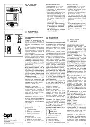
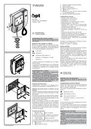
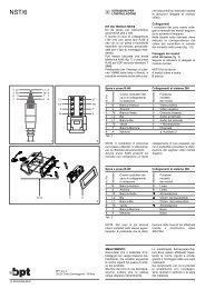
È munito dei seguenti comandi (fig. 1):<br />
Acceso/spento-luminosità<br />
Aux 1 - Pulsante a disposizione<br />
per comandi supplementari<br />
Aux 2 - Pulsante a disposizione<br />
per comandi supplementari<br />
Luce scale<br />
Inserimento-selezione posto<br />
esterno<br />
Apriporta<br />
Audio: mantenere premuto il<br />
pulsante per conversare<br />
I pulsanti Aux 1 e Aux 2 chiudono<br />
rispettivamente i morsetti 11 e 12<br />
verso il negativo (–) dell’alimentazione<br />
(24 V 100 mA max.).<br />
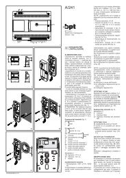
Il fusibile F1 di protezione tipo T 630<br />
mA è situato vicino ai dip-switch P<br />
(fig. 2).<br />
(Fusibile: F = rapido, T = ritardato).<br />
AVVERTENZE PER L’UTENTE<br />
- Non aprire o manomettere l’apparecchio;<br />
all’interno è presente alta<br />
tensione.<br />
- Evitare urti o colpi all’apparecchio<br />
che potrebbero provocare la rottura<br />
del cinescopio con conseguente<br />
proiezione di frammenti di vetro.<br />
- In caso di guasto, modifica o intervento<br />
sugli apparecchi dell’impianto<br />
(alimentatore, ecc.) avvalersi di personale<br />
specializzato.<br />
Il monitor è predisposto anche per<br />
operare in quattro modi speciali che<br />
possono essere selezionati mediante<br />
i dip-switch P di fig. 2 come segue:<br />
• Funzionamento in stand-by<br />
Normalmente escluso (dip-switch 1<br />
in posizione OFF, tempo di accensione<br />
6 s) il funzionamento in stand-by<br />
può essere attivato portando lo stesso<br />
dip-switch in posizione ON (tempo<br />
di accensione 2 s).<br />
• Funzionamento continuo<br />
Da utilizzare esclusivamente per fun-<br />
zioni di videocontrollo in impianti<br />
monofamiliari con telecamera, costantemente<br />
alimentata, separata dal<br />
posto esterno.<br />
Il monitor viene fornito con il dipswitch<br />
2 in posizione OFF.<br />
Per ottenere questo tipo di funzionamento<br />
è necessario portare il dipswitch<br />
in posizione ON.<br />
Lo spegnimento del monitor viene<br />
effettuato mediante l’interruttore<br />
acceso/spento-luminosità.<br />
• Accensione contemporanea di<br />
più monitor in parallelo mediante<br />
unica chiamata<br />
Per ottenere questo tipo di funzionamento<br />
da un gruppo di monitor collegati<br />
alla stessa chiamata è necessario:<br />
a) assicurarsi che su uno solo dei monitor<br />
il dip-switch 3 sia in posizione ON;<br />
b) portare in posizione OFF il dipswitch<br />
3 dei rimanenti monitor.<br />
• Spegnimento del monitor<br />
mediante il comando apriporta<br />
a) Impianti con alimentatore<br />
VA/100<br />
Il monitor viene normalmente spento<br />
mediante l’azionamento del comando<br />
apriporta (dip-switch 4 in posizione<br />
ON). Portando lo stesso dipswitch<br />
in posizione OFF il monitor si<br />
spegnerà a fine temporizzazione.<br />
b) Impianti con alimentatore<br />
VA/100.01<br />
Il dip-switch 4 deve essere in posizione<br />
OFF.<br />
Lo spegnimento del monitor è selezionato<br />
tramite il dip-switch 2 dell’alimentatore<br />
VA/100.01.<br />
Segnale di chiamata<br />
Il volume della nota di chiamata dal<br />
posto esterno è regolabile mediante il<br />
potenziometro accessibile dal foro Q<br />
sotto il monitor (fig. 2).<br />
MONITOR <strong>VM</strong>/<strong>110</strong>PA<br />
È munito dei seguenti comandi (fig. 1):<br />
Acceso/spento-luminosità<br />
Parlo-ascolto<br />
Aux 2 - Pulsante a disposizione<br />
per comandi supplementari<br />
Luce scale<br />
Inserimento-selezione posto<br />
esterno<br />
Apriporta<br />
Viva-voce<br />
Funzionamento del monitor a<br />
“viva-voce” e “parlo-ascolto”<br />
Viva-voce. Per effettuare la conversazione<br />
mantenere premuto il pulsante<br />
.<br />
Parlo-ascolto. Per parlare mantenere<br />
premuto il pulsante • e rilasciarlo per<br />
ascoltare.<br />
Le caratteristiche tecniche di funzionamento<br />
sono le stesse del monitor<br />
<strong>VM</strong>/<strong>110</strong>.<br />
Funzione dei morsetti<br />
1 segnale video<br />
2 schermo segnale video<br />
3 segnale video<br />
4 schermo segnale video<br />
5 – 14 ÷ 17,5 V<br />
6 + alimentazione monitor<br />
7 chiamata<br />
8 audio al monitor<br />
( 1 )<br />
1
9 audio al posto esterno<br />
10 uscita +11,5 V (50 mA max.)<br />
11 Aux 1 (solo per <strong>VM</strong>/<strong>110</strong>)<br />
12 Aux 2<br />
( 1 ) Resistenza di chiusura da 75 Ω<br />
se la linea non prosegue.<br />
Caratteristiche tecniche<br />
• Cinescopio: 8” (20 cm) a 90°.<br />
• Alimentazione: 14 ÷ 17,5 Vcc.<br />
• Assorbimento: 700 mA max. (60<br />
mA in stand-by, 5 mA a riposo).<br />
• Banda passante a -3dB: 6 MHz.<br />
• Ingresso video: 1 Vpp (da 0,7 a 2<br />
Vpp).<br />
• Impedenza d’ingresso video: >15<br />
kΩ.<br />
• Segnale di chiamata: bitonale<br />
regolabile.<br />
• Aux 1 e Aux 2: contatti normalmente<br />
aperti verso il negativo (–) dell’alimentazione<br />
(24 V 100 mA max.).<br />
•Temperatura di funzionamento: da<br />
0 °C a +35 °C.<br />
• Dimensioni: 184 x 184 x 200 mm.<br />
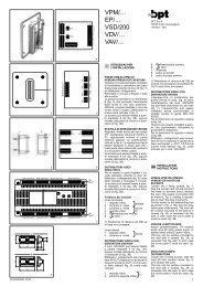
FISSAGGIO DEL MONITOR<br />
AL SUPPORTO DA INCASSO<br />
VKI/90 - VKI/170<br />
Inserire a fondo il monitor in modo<br />
che la parte terminale della scheda si<br />
innesti nel connettore della controscatola.<br />
Fissare il monitor mediante due staffe<br />
E evitando un serraggio eccessivo<br />
delle viti per non deformare il mobile<br />
(fig. 3).<br />
Inserire a pressione la mascherina.<br />
Per toglierla agire con un cacciavite<br />
come indicato in fig. 4.<br />
FISSAGGIO DEL MONITOR AL<br />
SUPPORTO DA TAVOLO VKT/<strong>110</strong><br />
Applicare il supporto da tavolo alla<br />
base del monitor. Innestare l’attacco<br />
del monitor e fissarlo mediante le due<br />
viti in dotazione (fig. 5).<br />
Con questa operazione si blocca<br />
anche il supporto da tavolo.<br />
FISSAGGIO DEL MONITOR AL<br />
SUPPORTO DA PARETE VKP/<strong>110</strong><br />
Inserire a fondo il monitor in modo<br />
che la parte terminale della scheda si<br />
innesti nel connettore del supporto e<br />
i due ganci G blocchino l’apparecchio<br />
(fig. 6).<br />
Avvitare le due viti H per evitare lo<br />
sganciamento accidentale del monitor<br />
(fig. 7).<br />
SMALTIMENTO<br />
Assicurarsi che il materiale d’imballaggio<br />
non venga disperso nell’ambiente,<br />
ma smaltito seguendo le<br />
norme vigenti nel paese di utilizzo del<br />
prodotto.<br />
Alla fine del ciclo di vita dell’apparecchio<br />
evitare che lo stesso venga disperso<br />
nell’ambiente.<br />
Lo smaltimento dell’apparecchiatura<br />
deve essere effettuato rispettando le<br />
norme vigenti e privilegiando il riciclaggio<br />
delle sue parti costituenti.<br />
Sui componenti, per cui è previsto lo<br />
smaltimento con riciclaggio, sono<br />
riportati il simbolo e la sigla del materiale.<br />
2<br />
GB INSTALLATION<br />
INSTRUCTIONS<br />
WARNING FOR THE INSTALLER<br />
These instructions should be attached<br />
to the receiver.<br />
HANDS FREE MONITOR <strong>VM</strong>/<strong>110</strong><br />
It is equipped with the following controls,<br />
figure 1:<br />
Thumb-wheel to switch the<br />
monitor ON/OFF and for the<br />
brightness control<br />
Aux 1 - Button for auxiliary<br />
services as required<br />
Aux 2 - Button for auxiliary<br />
services as required<br />
Button to turn on stairs light<br />
Button to bring the monitor<br />
live and manual sequencing<br />
of any additional panel/<br />
camera<br />
Door lock release button<br />
Audio button. To be kept<br />
depressed to converse<br />
Switches Aux 1 and Aux 2 are normally<br />
open, when actuated the contacts<br />
close on – 0 V DC. Max. current<br />
demand 100 mA at 24 V.<br />
The monitor is protected by the slow<br />
blow fuse F1 - T 630 mA - mounted<br />
next to the dip-switches P, figure 2.<br />
(Fuse: F = fast, T = slow).<br />
WARNINGS FOR THE USER<br />
- Please do not open or tamper with<br />
the device (high voltage!).<br />
- Please avoid knocking or bumping<br />
the apparatus as it could result in the<br />
breakage of the picture tube and the<br />
consequent projection of glass fragments.<br />
- In the case of breakdown or modification<br />
of the apparatus (such as<br />
power supplier…) please contact a<br />
specialized maintenance service.<br />
Four special monitor operation modes<br />
can be chosen by means of dip-switches<br />
P accessible from the rear of the<br />
monitor. Figure 2 shows position of<br />
dip-switches as supplied.<br />
• Stand-by mode<br />
The dip-switch 1 is normally kept in<br />
the OFF position - the stand-by mode<br />
is not operating - the picture appears<br />
on the screen in 6 s approx.<br />
In the ON position it activates the<br />
stand-by, the picture appears on the<br />
screen almost instantaneously.<br />
• Monitor in constant mode<br />
For use only in single house installations<br />
as close circuit television system<br />
with camera always powered and<br />
separated from entry panel.<br />
<strong>VM</strong>/100 is supplied from the factory<br />
with dip-switch 2 in the OFF position.<br />
The constant mode is achieved with<br />
dip-switch 2 set to ON position.<br />
The monitor can only be switched off<br />
by ON/OFF and brightness control<br />
thumb-wheel.<br />
• Activation of more monitors by<br />
the same call<br />
Dip-switch 3 is normally kept in the<br />
ON position, this way the call line<br />
loop is closed. If more monitors must<br />
be activated by the same call, leave<br />
only one with the jumper 3 in the ON<br />
position, all other monitors must have<br />
the dip-switch 3 in the OFF position.<br />
Failure to have the dip-switches in the<br />
correct positions will result in the<br />
monitors not being activated.<br />
• Monitor/system turned off on<br />
door release<br />
a) Installations with VA/100 main<br />
control unit<br />
Dip-switch 4 is normally kept in the<br />
ON position. In this position the monitor<br />
is turned off by pressing the door<br />
lock release button.<br />
With dip-switch 4 in the OFF position<br />
the system will stay on when pressing<br />
the door lock release button on monitor<br />
and will be turned off automatically<br />
by the system timer.<br />
b) Installations with VA/100.01 main<br />
control unit<br />
Dip-switch 4 must be in the OFF position.<br />
Use dip-switch 2 of the VA/100.01 main<br />
control unit to turn off the monitor.<br />
Call tone<br />
It is possible to regulate the call tone<br />
level from the entry panel by adjusting<br />
the trimmer, accessible from the<br />
Q hole placed on the right side of the<br />
monitor, figure 2.<br />
HANDS FREE MONITOR <strong>VM</strong>/<strong>110</strong>PA<br />
It is equipped with the following controls,<br />
figure 1:<br />
Thumb-wheel to switch the<br />
monitor ON/OFF and for the<br />
brightness control<br />
Talk or listen button<br />
Aux 2 - Button for auxiliary<br />
services as required<br />
Button to turn on stairs light<br />
Button to bring the monitor<br />
live and manual sequencing<br />
of any additional panel/camera<br />
Door lock release button<br />
Talk and listen button<br />
Monitor operating in the “talk and<br />
listening” mode and “talk or listening”<br />
mode.<br />
Talk and listening mode. To converse<br />
in the “talk and listening” mode keep<br />
the button on monitor depressed.<br />
Talk or listening mode. In the “talk or<br />
listening” mode press the • button on<br />
monitor to speak, release it to listen.<br />
All other operation modes are identical<br />
to <strong>VM</strong>/<strong>110</strong> monitor.<br />
Function of each terminal<br />
1 video signal<br />
( 1 2 video signal shield<br />
)<br />
3 video signal<br />
4 video signal shield<br />
5 – 14 ÷ 17.5 V<br />
6 + supply voltage to monitor<br />
7 call<br />
8 audio to monitor<br />
9 audio to entry panel<br />
10 +11.5V DC voltage output ( 2 )<br />
11 Aux 1 (only for <strong>VM</strong>/<strong>110</strong>)<br />
12 Aux 2<br />
( 1 ) 75 Ω closing resistance if video<br />
line stops here.<br />
( 2 ) This voltage output is available for<br />
the time the monitor is operating.<br />
Max. current demand should not<br />
exceed 50mA.<br />
Technical features<br />
• Picture screen: 8” (20 cm) 90°.<br />
• Supply voltage: 14 ÷ 17.5 V DC.<br />
• Current demand: 700 mA (60 mA<br />
in stand-by, 5 mA quiescent).<br />
• Bandwidth response at -3dB: 6<br />
MHz.<br />
•Video input: 1 Vpp (from 0.7 Vpp to<br />
2 Vpp).<br />
•Video input impedance: >15 kΩ.<br />
• Call signal: electronic dual tone<br />
note, the call volume can be regulated.<br />
• Aux 1 and Aux 2: normally open<br />
switches, when actuated the contact<br />
closes to 0 V DC.<br />
Current demand should not<br />
exceed 100 mA at 24 V.<br />
•Working temperature range: from 0<br />
°C to +35 °C.<br />
• Dimensions: 184 x 184 x 200 mm.<br />
FIXING THE MONITOR<br />
IN THE VKI/90 - VKI/170<br />
RECESSED MOUNTING<br />
Slide the monitor into the frame until<br />
the monitor printed card is firmly inserted<br />
into the terminal connector of the<br />
frame.<br />
Fasten the monitor with the 2 brackets<br />
E avoiding excessive tightening of the<br />
screws not to deform the frame, figure<br />
3. Put the cover on top of frame box.<br />
To take it off use a screwdriver as<br />
shown in figure 4.<br />
FIXING THE MONITOR IN THE<br />
VKT/<strong>110</strong> TABLE-TOP MOUNTING<br />
Attach the support to the monitor,<br />
plug in the coupling connector and<br />
secure both with 2 screws, fugure 5.<br />
FIXING THE MONITOR IN THE<br />
VKP/<strong>110</strong> WALL MOUNTING<br />
Slide the monitor onto the support<br />
checking to see that the monitor printed<br />
card is firmly inserted into the<br />
support terminal connector and the<br />
monitor itself is held by the 2 hooks<br />
G, figure 6. Tighten the 2 screws H to<br />
avoid accidental unfastening of the<br />
monitor, figure 7.<br />
DISPOSAL<br />
Do not litter the environment with<br />
packing material: make sure it is disposed<br />
of according to the regulations<br />
in force in the country where the<br />
product is used.<br />
When the equipment reaches the end<br />
of its life cycle, take measures to<br />
ensure it is not discarded in the environment.<br />
The equipment must be disposed of<br />
in compliance with the regulations in<br />
force, recycling its component parts<br />
wherever possible.<br />
Components that qualify as recyclable<br />
waste feature the relevant symbol<br />
and the material’s abbreviation.<br />
D INSTALLATIONS-<br />
ANLEITUNG<br />
ACHTUNG!<br />
NUR FÜR INSTALLATEUR<br />
Diese Anleitungen müßen jede der<br />
Sprechstelle begleiten.<br />
MONITOR <strong>VM</strong>/<strong>110</strong><br />
Mit folgenden Funktionen ausgestattet<br />
(Abb. 1):<br />
EIN/AUS, Helligkeit
Aux 1 - Taste für zusätzlich<br />
gewünschte Serviceschaltung<br />
Aux 2 - Taste für zusätzlich<br />
gewünschte Serviceschaltung<br />
Taste für Treppenlicht<br />
Taste zur Bildeinund Kameraweiterschaltung<br />
von zusätzlichen<br />
Kamerastellen<br />
Türöffnertaste<br />
Ton<br />
Die Tasten Aux 1 und Aux 2 (24 V, 100<br />
mA max.) verbinden Klemme 11 bzw.<br />
12 mit minus Pol des Netzgerätes.<br />
Der Monitor ist durch die Sicherung F1<br />
- T 630 mA - geschützt, die neben dem<br />
Kodierschalter Abb. 2, angebracht ist.<br />
(Sicherung: F = flink, T = träge).<br />
HINWEISE FÜR DEN NUTZER<br />
- Bitte Gerät nicht öffnen oder aufbrechen<br />
(hohe Spannung!).<br />
- Zur Vermeidung eines Bildröhrenbruchs,<br />
Stösse und Schläge unterlassen.<br />
- Bei Störungen, Änderungen oder<br />
Reparaturen an den Geräten (Netzgerät,<br />
usw.) nur an Spezialisten wenden.<br />
Vier spezielle Funktionen können durch<br />
Kodierschalter P auf der Rückseite des<br />
Monitors ausgewählt werden, Werksseitige<br />
Einstellung siehe Abb. 2.<br />
• Stand-By-Betrieb<br />
Der Kodierschalter 1 ist normalerweise<br />
ausgeschaltet (Kodierschalter in OFF-<br />
Position), das Bild erscheint in ca. 6 s,<br />
auf dem Bildschirm. Stand-By eingeschaltet<br />
erscheint das Bild sofort.<br />
• Monitor in Dauerbetrieb<br />
Nur in Einfamilienhaus-Installation<br />
möglich, als Überwachungssystem<br />
mit von der Außenstation abgesetzter<br />
Kamera.<br />
<strong>VM</strong>/100 wird werkseitig mit Kodierschalter<br />
2 in OFF-Position geliefert.<br />
Für Dauerbetrieb ist der Kodierschalter<br />
2 in ON-Position zu stellen.<br />
Der Monitor kann nur über den<br />
EIN/AUS-Schalter, Abb. 1, abgeschaltet<br />
werden.<br />
• Einschaltung von Monitor mit<br />
gleichem Anruf<br />
Die Kodierschalter 3 ist normalerweise<br />
in ON-Position geschaltet, dadurch<br />
ist die Ruflinie geschlossen.<br />
Wenn mehr Monitore mit einem Anruf<br />
eingeschaltet werden sollen, ist nur<br />
ein Monitor mit Kodierschalter 3 in<br />
ON-Position zu schalten und alle<br />
anderen in OFF-Position.<br />
• Monitor-/Systemausschaltung<br />
durch Türöffnertaste<br />
a) Anlagen mit Netzgerät VA/100<br />
Der Kodierschalter 4 ist normalerweise<br />
werksseiting in ON-Position<br />
geschaltet.<br />
In dieser Position wird bei betätigung<br />
der Türöffnertaste das System abgeschaltet.<br />
Wird der Kodierschalter in OFF-<br />
Position geschaltet bleibt das Bild<br />
auch bei betätigung des Türöffners<br />
bis zur automatischen Abschaltung<br />
des Systems erhalten.<br />
b) Anlagen mit Netzgerät<br />
VA/100.01<br />
Kodierschalter 4 muß auf OFF-<br />
Position geschaltet sein.<br />
Abschalten der Innenabzweigung über<br />
dip-switch 2 an Netzgerät VA/100.01.<br />
Rufton<br />
Die Lautstärke des Rufton kann am<br />
Potentiometer, der sich auf der rechten<br />
Anschlußleiste der Monitorrückseite<br />
befindet eingestellt werden<br />
(Abb. 2).<br />
MONITOR <strong>VM</strong>/<strong>110</strong>PA<br />
Mit folgenden Funktionen ausgestattet<br />
(Abb. 1):<br />
EIN/AUS, Helligkeit<br />
Gegensprech<br />
Aux 2 - Taste für zusätzlich<br />
gewünschte Serviceschaltung.<br />
Taste für Treppenlicht<br />
Taste zur Bildeinund Kameraweiterschaltung<br />
von zusätzlichen<br />
Kamerastellen<br />
Türöffnertaste<br />
Wechselsprech<br />
Bedienungsanleitung für “Wechselsprech”<br />
und “Gegensprech”<br />
Wechselsprechen. Taste drücken,<br />
sprechen und hörer.<br />
Gegensprechen. Taste • drücken,<br />
sprechen Taste loslassen, hörer.<br />
Alle anderen Funktionen sind identisch<br />
zu Monitor <strong>VM</strong>/<strong>110</strong>.<br />
Belegung der Klemmleisten<br />
1 Videosignal<br />
( 1 2 Videosignalabschirmung<br />
)<br />
3 Videosignal<br />
4 Videosignalabschirmung<br />
5 – 14 ÷ 17,5 V<br />
6 + Monitorversorgung<br />
7 Anruf<br />
8 Ton zum Monitor<br />
9 Ton zur Außenstation<br />
10 Ausgang +11,5V (max. 50 mA)<br />
11 Aux 1 (nür für <strong>VM</strong>/<strong>110</strong>)<br />
12 Aux 2<br />
( 1 )75Ω Abschlußwiderstand bei<br />
Nichtfortführung der Linie.<br />
Technische Daten<br />
• Bildröhre: 8-Zoll (20 cm) - 90°<br />
Ablenkung.<br />
• Stromversorgung: 14÷17,5V DC.<br />
• Stromaufnahme: 700 mA max.<br />
(60mA in Stand-By-Betrieb, 5 mA<br />
Ruhestrom).<br />
•Videobandbreite bei -3dB: 6MHz.<br />
•Videoeingang: 1 Vss (von 0,7 bis 2<br />
Vss).<br />
•Video-Eingangsimpedanz: >15 kΩ.<br />
• Rufzeichen: Zweiklangton, einstellbar.<br />
• Aux 1 und Aux 2: Schließkontakte<br />
zum Anschluß an die Minusklemme<br />
der Stromversorgung (24 V 100 mA<br />
max.).<br />
• Betriebstemperatur: von 0 °C bis<br />
+35 °C.<br />
• Abmessungen: 184 x 184 x 200 mm.<br />
ZUSAMMENBAU DES MONITORS<br />
MIT UP-MONTAGEHALTER<br />
VKI/90 - VKI/170<br />
Monitor einsetzen, so daß die<br />
Anschlußleiste des Monitors mit der<br />
Klemmleiste des Einbausatzes kontaktiert.<br />
Monitor mit den Halterungen E befestigen,<br />
wobei die Schrauben nur<br />
leicht anzuziehen sind, damit das<br />
Monitorgehäuse nicht verformt wird<br />
(Abb. 3). Blende aufsetzen.<br />
Um die Blende zu entfernen ist ein<br />
Schraubenzieher (Abb. 4) zu verwenden.<br />
ZUSAMMENBAU DES MONITORS<br />
MIT TICHMONTAGEHALTER<br />
VKT/<strong>110</strong><br />
Monitorträger anbringen und Steckerleiste<br />
mit Kabelsatz einstecken und<br />
mit zwei Schrauben befestigen (Abb.<br />
5).<br />
ZUSAMMENBAU DES MONITORS<br />
MIT WANDMONTAGEHALTER<br />
VKP/<strong>110</strong><br />
Monitor auf die Konsole anbringen,<br />
so daß die Anschlußleiste des<br />
Monitors mit der Klemmleiste der<br />
Wandkonsole verbunden ist und die<br />
Haltebülgel G (Abb. 6) einrasten.<br />
Monitor mit Konsole durch zwei<br />
Schauben H (Abb. 7) sichern.<br />
ENTSORGUNG<br />
Vergewissern Sie sich, dass das<br />
Verpackungsmaterial gemäß den<br />
Vorschriften des Bestimmungslandes<br />
ordungsgemäß und umweltgerecht<br />
entsorgt wird.<br />
Das nicht mehr benutzbare Gerät ist<br />
umweltgerecht zu entsorgen.<br />
Die Entsorgung hat den geltenden<br />
Vorschriften zu entsprechen und<br />
vorzugsweise das Recycling der<br />
Geräteteile vorzusehen.<br />
Die wiederverwertbaren Geräteteile<br />
sind mit einem Materialsymbol und<br />
–zeichen versehen.<br />
F INSTRUCTIONS<br />
POUR L’INSTALLATION<br />
PRECAUTIONS<br />
POUR L’INSTALLATEUR<br />
Cettes instructions doivent accompagner<br />
chaque poste intérieur.<br />
MONITEUR <strong>VM</strong>/<strong>110</strong><br />
Doté des commandes suivantes (fig. 1):<br />
Marche/Arrêt et réglage de<br />
la luminosité<br />
Bouton-poussoir disponible<br />
pour commandes auxiliaires<br />
(Aux 1)<br />
Bouton-poussoir disponible<br />
pour commandes auxiliaires<br />
(Aux 2)<br />
Commande de minuterie<br />
Mise en marche-sélection<br />
des postes extérieurs<br />
Commande ouvre-porte<br />
(gâche-électrique)<br />
Touche assurant la liaison<br />
phonique en duplex<br />
Les boutons Aux 1 et Aux 2 (dont le<br />
pouvoir de coupure est de 24 V, 100<br />
mA maxi) relient respectivement les<br />
bornes 11 et 12 au négatif (–) de l’alimentation.<br />
Le fusibile F1 de protection du type T<br />
630 mA est placé à côté des dipswitch<br />
de la fig. 2.<br />
(Fusible: F = rapide, T = retardé).<br />
PRECAUTIONS POUR L’USAGER<br />
- Ne pas ouvrir et ne pas touche l’appareil:<br />
attention haute tension!<br />
- Eviter les chocs qui pourraient provoquer<br />
l’implosion du tube cathodique<br />
et la projection de fragments de verre.<br />
- En cas de défaut, de modification<br />
ou d’intervention sur les appareils de<br />
l’installation (alimentation, etc.), s’adresser<br />
exclusivement au personnel<br />
spécialisé.<br />
Le moniteur est équipé avec dipswitch<br />
P (fig. 2) qui permettent la<br />
sélection des quatre modes spéciales<br />
de fonctionnement suivants:<br />
• Fonctionnement en stand-by<br />
Normalement hors service (dipswitch<br />
1 en position OFF, temps d’allumage<br />
6 s) le préchauffage est obtenu<br />
en portant le dip-switch 1 en position<br />
ON (temps d’allumage 2 s).<br />
• Fonctionnement en service continu<br />
À utiliser exclusivement en vidéo-surveillance<br />
dans les installations villa et<br />
avec télécaméra, alimentée en permanence,<br />
séparée du poste extérieur.<br />
Le moniteur est fourni avec le dipswitch<br />
2 en position OFF.<br />
Cet fonctionnement peut être établi<br />
en plaçant ledit cavalier en position<br />
ON. L’extinction du moniteur s’obtient<br />
à l’aide de l’interrupteur marche/<br />
arrêt-luminosité.<br />
• Allumage simultané de plusieurs<br />
moniteurs en parallèle sur signal<br />
d’appel unique<br />
Pour obtenir la mise en marche d’un<br />
groupe de moniteurs reliés sur un<br />
seul appel placer le dip-switch 3 sur<br />
un seul des moniteurs en position<br />
ON; les autres moniteurs devront<br />
avoir le dip-switch 3 en position OFF.<br />
• Extinction du moniteur par la<br />
commande ouvre-porte<br />
a) Installations avec alimentation<br />
VA/100<br />
L’arrêt du moniteur est obtenu normalement<br />
par la commande d’ouverture<br />
de la gâche (dip-switch 4 en<br />
position ON).<br />
En plaçant le même dip-switch en<br />
position OFF, le moniteur restera allumé<br />
jusqu’à la fin de la temporisation.<br />
b) Installations avec alimentation<br />
VA/100.01<br />
Le dip-switch 4 doit être positionné<br />
sur OFF.<br />
On sélectionne l’interruption du moniteur<br />
au moyen du dip-switch 2 de l’alimentation<br />
VA/100.01.<br />
Signal d’appel<br />
L’intensité de la note d’appel provenant<br />
du poste extérieur est réglable à<br />
l’aide d’un potentiomètre. Utiliser un<br />
petit tournevis à travers la fente Q de<br />
la fig. 2.<br />
MONITEUR <strong>VM</strong>/<strong>110</strong>PA<br />
Doté des commandes suivantes (fig. 1):<br />
Marche/Arrêt - réglage de la<br />
luminosité<br />
Touche assurant la liaison<br />
phonique en “parole-ecoute”<br />
Bouton-poussoir disponible<br />
pour commandes auxiliaires<br />
(Aux 2)<br />
Commande de minuterie<br />
Mise en marche-sélection<br />
des postes extérieurs<br />
3
Commande ouvre-porte<br />
(gâche-électrique)<br />
Touche assurant la liaison<br />
phonique en duplex<br />
Fonctionnement de l’appareil en<br />
“duplex” et en “parole-ecoute”<br />
Duplex. Appuyer sur le bouton<br />
pendant toute la conversation.<br />
Parole-ecoute. Appuyer sur le bouton •<br />
pour parler et le relâcher pour écouter.<br />
Les autres caractéristiques de fonctionnement<br />
sont le mêmes du moniteur<br />
<strong>VM</strong>/<strong>110</strong>.<br />
Fonction des bornes<br />
1 signal vidéo<br />
( 1 2 blindage signal vidéo<br />
)<br />
3 signal vidéo<br />
4 blindage signal vidéo<br />
5 – 14 ÷ 17,5V<br />
6 + alimentation du moniteur<br />
7 appel<br />
8 audio au moniteur<br />
9 audio au poste extérieur<br />
10 sortie +11,5V (50 mA max.)<br />
11 Aux 1 (seulement pour <strong>VM</strong>/<strong>110</strong>)<br />
12 Aux 2<br />
( 1 ) Résistence 75Ω de fin de ligne.<br />
Caracteristiques techniques<br />
•Tube: 8” (20 cm) à 90°.<br />
• Alimentation: 14 ÷ 17,5 Vcc.<br />
• Consommation: 700 mA maxi (60<br />
mA en stand-by, 5 mA à repos).<br />
• Bande passante à -3dB: 6 MHz.<br />
• Entrée vidéo: 1Vpp (de 0,7 à 2 Vpp).<br />
• Impédance d’entrée vidéo: >15 kΩ.<br />
• Note d’appel: électronique, bitonale,<br />
réglable.<br />
• Aux 1 et Aux 2: contacts normalement<br />
ouverts sur le négatif de l’alimentation<br />
(pouvoir de coupure: 24<br />
V 100 mA maxi).<br />
•Température de fonctionnement:<br />
de 0 °C à +35 °C.<br />
• Dimensions: 184x184x 200 mm.<br />
FIXATION DU MONITEUR AU<br />
SUPPORT D’ENCASTREMENT<br />
VKI/90 - VKI/170<br />
Longer à fond le moniteur lafin que<br />
sa fiche s’enclipse dans la prise du<br />
contre-boîtier.<br />
Fixer le moniteur à l’aide des deux<br />
étriers sans serrer excessivement les<br />
vis pour éviter toute deformation (fig.<br />
3). Placer le cadre en faisant pression;<br />
pour l’ôter, utiliser un tournevis<br />
comme indiqué en la fig. 4.<br />
FIXATION DU MONITEUR AU<br />
SUPPORT DE TABLE VKT/<strong>110</strong><br />
Enclipser le support de table sur la<br />
base du moniteur.<br />
Enficher l’adapteur et le fixer à l’aide<br />
des deux vis fournies à cet effet (fig.<br />
5). Cette opération assure le blocage<br />
du support de table.<br />
FIXATION DU MONITEUR AU<br />
SUPPORT MURAL VKP/<strong>110</strong><br />
Loger à fond le moniteur de façon à<br />
ce que la partie arrière du circuit<br />
imprimé de celui-ci s’enclipse dans<br />
le connecteur du support.<br />
S’assurer que l’appareil soit accroché<br />
aux deux éléments G (fig. 6) et le bloquer<br />
à l’aide des deux vis H (fig. 7).<br />
ELIMINATION<br />
S'assurer que le matériel d’emballage<br />
n’est pas abandonné dans la<br />
nature et qu’il est éliminé conformément<br />
aux normes en vigueur dans le<br />
pays d'utilisation du produit.<br />
4<br />
À la fin du cycle de vie de l'appareil,<br />
faire en sorte qu'il ne soit pas abandonné<br />
dans la nature.<br />
L'appareil doit être éliminé conformément<br />
aux normes en vigueur et en privilégiant<br />
le recyclage de ses pièces.<br />
Le symbole et le sigle du matériau<br />
sont indiqués sur les pièces pour<br />
lesquelles le recyclage est prévu.<br />
E INSTRUCCIONES<br />
PARA LA INSTALACION<br />
ADVERTENCIA AL INSTALADOR<br />
Estas instrucciones se deben ser<br />
adjuntadas al derivado interno.<br />
MONITOR <strong>VM</strong>/<strong>110</strong><br />
Está dotado de los siguientes mandos<br />
(fig. 1):<br />
Encendido/apagado-luminosidad<br />
Aux 1 - Pulsador disponible<br />
para mandos suplementarios<br />
Aux 2 - Pulsador disponible<br />
para mandos suplementarios<br />
Luz de la escalera<br />
Activación-selección de la<br />
placa exterior<br />
Abrepuerta<br />
Audio: mantener el pulsador<br />
presionado para conversar<br />
Los pulsadores Aux 1 y Aux 2 cierran<br />
respectivamente los bornes 11 y 12<br />
hacia el negativo (–) de la alimentación<br />
(24V 100mA máx.).<br />
El fusible F1 de protección tipo T 630<br />
mA, esta situado cerca de los dipswitch<br />
P (fig. 2).<br />
(Fusible: F = rápido, T = retardado).<br />
ADVERTENCIAS<br />
PARA EL USUARIO<br />
- No abrir ni manipular el aparato: en<br />
el interior hay alta tensión.<br />
- Evitar choques y golpes al aparato<br />
que pueden causar explosión del<br />
tubo catódico y proyección de fragmentos<br />
de vidrio.<br />
- En caso de avería o necesidad de<br />
modificación o intervención sobre los<br />
aparatos de la instalación (alimentador,<br />
etc.) dirigirse al personal especializado.<br />
El monitor también está preparado<br />
para funcionar en cuatro modos<br />
especiales, que pueden seleccionarse<br />
mediante los dip-switch P de la fig.<br />
2, a saber:<br />
• Funcionamiento en stand-by<br />
Normalmente excluido (dip-switch 1<br />
en posición OFF, tiempo de encendido<br />
6 s).<br />
El funcionamiento en stand-by se<br />
puede activar colocando el mismo<br />
dip-switch en la posición ON (tiempo<br />
de encendido 2 s).<br />
• Funcionamiento contínuo<br />
Destinado exclusivamente a funciones<br />
de videocontrol en equipos<br />
monofamiliares con telecámara constantemente<br />
alimentada y separada<br />
de la placa exterior.<br />
El monitor se entrega con el dipswitch<br />
2 en posición OFF.<br />
Para obtener este tipo de funcionamiento<br />
es necesario colocarlo en la<br />
posición ON.<br />
Para apagar el monitor se utiliza el<br />
interruptor de encendido/apagadoluminosidad.<br />
• Encendido simultáneo de varios<br />
monitores en paralelo mediante<br />
una sola llamada<br />
Para conseguir este tipo de funcionamiento<br />
de un grupo de monitores<br />
conectados a la misma llamada es<br />
necesario:<br />
a) asegurarse de que en uno solo de<br />
los monitores el dip-switch 3 está en<br />
la posición ON;<br />
b) colocar el dip-switch 3 de los<br />
demás monitores en posición OFF.<br />
• Apagado del monitor mediante<br />
el mando abrepuerta<br />
a) En equipos con alimentador<br />
VA/100<br />
El monitor se apaga normalmente al<br />
accionarse el mando abrepuerta<br />
(dip-switch 4 en posición ON).<br />
Colocando el mismo dip-switch en<br />
posición OFF, el monitor se apagará<br />
al finalizar la temporización.<br />
b) En equipos con alimentador<br />
VA/100.01<br />
El dip-switch 4 se debe colocar en<br />
OFF.<br />
El apagado del monitor se selecciona<br />
mediante el dip-switch 2 del alimentador<br />
VA/100.01.<br />
Señal de llamada<br />
El volumen de la nota de llamada<br />
desde la placa exterior se puede<br />
regular mediante el potenciómetro<br />
accesible desde el orificio Q, bajo el<br />
monitor (fig. 2).<br />
MONITOR <strong>VM</strong>/<strong>110</strong>PA<br />
Está dotado de los siguientes mandos<br />
(fig. 1):<br />
Encendido/apagado-luminosidad<br />
Habla-escucha<br />
Aux 2 - Pulsador disponible<br />
para mandos suplementarios<br />
Luz de la escalera<br />
Activación-selección de la<br />
placa exterior<br />
Abrepuerta<br />
Escucha amplificada<br />
Funcionamiento del monitor con<br />
“escucha amplificada” y “hablaescucha”<br />
Escucha amplificada. Para realizar la<br />
conversación, mantener presionado<br />
el pulsador .<br />
Habla-escucha. Para hablar, mantener<br />
pulsado el pulsador •, y soltarlo<br />
para escuchar.<br />
Las demás características de funcionamiento<br />
son iguales a las del monitor<br />
<strong>VM</strong>/<strong>110</strong>.<br />
Funciones de los bornes<br />
1 señal de vídeo<br />
2 pantalla señal de vídeo<br />
3 señal vídeo<br />
4 pantalla señal de vídeo<br />
5 – 14 ÷ 17,5V<br />
6 + alimentación monitor<br />
7 llamada<br />
( 1 )<br />
8 audio al monitor<br />
9 audio a la placa exterior<br />
10 salida +11,5 V (50 mA máx.)<br />
11 Aux 1 (solo para <strong>VM</strong>/<strong>110</strong>)<br />
12 Aux 2<br />
( 1 ) Resistencia de cierre de 75 Ω si la<br />
línea no continúa.<br />
Características técnicas<br />
• Cinescopio: 8” (20 cm) a 90°.<br />
• Alimentación: 14 ÷ 17,5 Vcc.<br />
• Absorción: 700 mA máx. (60 mA<br />
en stand-by, 5 mA en reposo).<br />
• Banda pasante: 6 MHz a -3dB.<br />
• Entrada vídeo: 1 Vpp (de 0,7 a 2<br />
Vpp).<br />
• Impedancia de entrada vídeo:<br />
>15 KΩ.<br />
• Señal de llamada: bitonal, con<br />
volumen regulable.<br />
• Aux 1 y Aux 2: contactos normalmente<br />
abiertos hacia el negativo<br />
(–) de la alimentación (24 V 100<br />
mA máx.).<br />
• Temperatura de funcionamiento:<br />
de 0 °C a +35 °C.<br />
• Dimensiones: 184x184x200 mm<br />
COLOCACION DEL MONITOR<br />
EN SU SOPORTE DE EMPOTRAR<br />
VKI/90 - VKI/170<br />
Encajar a fondo el monitor, de manera<br />
que la parte terminal de la tarjeta se<br />
inserte en el conector de la contracaja.<br />
Fijar el monitor mediante los dos<br />
soportes E.<br />
No ajustar excesivamente los tornillos<br />
para evitar que se deforme el<br />
mueble (fig. 3).<br />
Montar a presión el cuadro. Para quitarlo,<br />
servirse de un destornillador<br />
como se ilustra en la fig. 4.<br />
COLOCACION DEL MONITOR EN<br />
SU SOPORTE DE SOBREMESA<br />
VKT/<strong>110</strong><br />
Aplicar el soporte de sobremesa a la<br />
base del monitor. Insertar el acople<br />
del monitor y fijarlo mediante los dos<br />
tornillos respectivos (fig. 5).<br />
Con esta operación se bloquea también<br />
el soporte de sobremesa.<br />
COLOCACION DEL MONITOR<br />
EN SU SOPORTE DE PARED<br />
VKP/<strong>110</strong><br />
Encajar a fondo el monitor, de manera<br />
que la parte terminal de la tarjeta se<br />
inserte en el conector del soporte, y<br />
los dos ganchos G bloqueen el aparato<br />
(fig. 6). Ajustar los dos tornillos H<br />
para evitar que el monitor se desenganche<br />
accidentalmente (fig. 7).<br />
ELIMINACION<br />
Comprobar que no se tire al medioambiente<br />
el material de embalaje,<br />
sino que sea eliminado conforme<br />
a las normas vigentes en el<br />
país donde se utilice el producto.<br />
Al final del ciclo de vida del aparato<br />
evítese que éste sea tirado al<br />
medioambiente.<br />
La eliminación del aparato debe<br />
efectuarse conforme a las normas<br />
vigentes y privilegiando el reciclaje<br />
de sus partes componentes.<br />
En los componentes, para los cuales<br />
está prevista la eliminación con reciclaje,<br />
se indican el símbolo y la sigla<br />
del material.