VSE/301 2408-0400 10.05 - TECH FASS sro
VSE/301 2408-0400 10.05 - TECH FASS sro
VSE/301 2408-0400 10.05 - TECH FASS sro

Create successful ePaper yourself
Turn your PDF publications into a flip-book with our unique Google optimized e-Paper software.
In presenza di derivati interni non<br />
intercomunicanti è necessario<br />
informare il selettore della loro presenza<br />
premendo il pulsante Aux 2<br />
(nessun tono di conferma).<br />
4- Uscire dalla programmazione<br />
rimettendo il ponticello SW1.<br />
ATTENZIONE. Negli impianti con<br />
XA/300LR si raccomanda di raccogliere<br />
i codici identificativi ID (SN) dei<br />
derivati, applicati all’esterno del<br />
mobile, e riportarli nelle tabelle allegate<br />
alle apparecchiature XA/300LR,<br />
MPP/300LR e IPC/300LR.<br />
Aggiunta o sostituzione<br />
di un derivato interno<br />
Qualora si voglia aggiungere o<br />
sostituire nell’impianto un derivato<br />
interno, seguire la procedura<br />
descritta ai punti 1 e 4 del paragrafo<br />
“Programmazione del<br />
<strong>VSE</strong>/<strong>301</strong>”.<br />
Caratteristiche tecniche<br />
• Alimentazione: 230 Vca 50/60 Hz<br />
+6% –10%.<br />
L’apparecchio è protetto elettronicamente<br />
contro sovraccarichi<br />
e cortocircuiti.<br />
• Potenza assorbita: 45 VA.<br />
• Alimentazione derivati interni<br />
mediante bus: 20 Vcc (morsettiera<br />
M2).<br />
• L’apparecchio <strong>VSE</strong>/<strong>301</strong> può alimentare<br />
da solo:<br />
- 1 derivato interno intercomunicante<br />
e 9 in stand-by.<br />
• Derivati interni attivabili con la<br />
stessa chiamata: 10 (se videocitofonici<br />
prevedere l’alimentazione<br />
locale di 9 derivati).<br />
• Linea di trasmissione verso i<br />
derivati: doppino non polarizzato<br />
(Z=100 Ω).<br />
• Linea di collegamento verso la<br />
linea principale: doppino non<br />
polarizzato (Z = 100 Ω).<br />
• Chiamata dal pianerottolo: tono<br />
continuo di 3 s.<br />
• Tempo della nota di chiamata<br />
intercomunicante: 30 s.<br />
• Distanze massime: 100 m tra il<br />
selettore ed ultimo derivato collegato<br />
all’impianto (con cavo<br />
VCM/1D).<br />
• Numero massimo di selettori presenti<br />
in un impianto sistema 300<br />
(XA/300LR): 100.<br />
• Numero massimo di selettori presenti<br />
in un impianto sistema X2:<br />
25.<br />
• Temperatura di funzionamento:<br />
da 0 °C a +35 °C.<br />
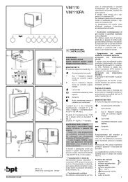
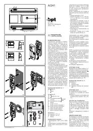
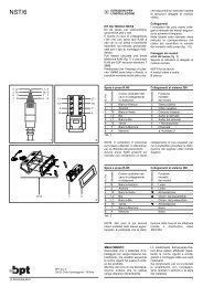
• Dimensioni: modulo da 8 unità<br />
basso per guida DIN (fig. 2).<br />
L’apparecchio può essere installato,<br />
senza coprimorsetti, in scatole<br />
munite di guida DIN (EN 50022).<br />
Per le dimensioni di ingombro<br />
vedere la fig. 2A.<br />
Oppure può essere installato a<br />
parete utilizzando la guida DIN in<br />
dotazione ed applicando il coprimorsetti.<br />
Per le dimensioni di ingombro<br />
vedere la fig. 2B.<br />
SMALTIMENTO<br />
Assicurarsi che il materiale d’im-<br />
2<br />
ballaggio non venga disperso nell’ambiente,<br />
ma smaltito seguendo<br />
le norme vigenti nel paese di utilizzo<br />
del prodotto.<br />
Alla fine del ciclo di vita dell’apparecchio<br />
evitare che lo stesso<br />
venga disperso nell’ambiente.<br />
Lo smaltimento dell’apparecchiatura<br />
deve essere effettuato rispettando<br />
le norme vigenti e privilegiando<br />
il riciclaggio delle sue parti<br />
costituenti.<br />
Sui componenti, per cui è previsto<br />
lo smaltimento con riciclaggio,<br />
sono riportati il simbolo e la sigla<br />
del materiale.<br />
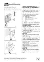
GB INSTALLATION<br />
INSTRUCTIONS<br />
SELECTOR FOR INTERCOMS<br />
<strong>VSE</strong>/<strong>301</strong><br />
Using the selector, different groups<br />
of intercom receivers can be connected<br />
with the main line of an X1,<br />
X2 systems or system 300 installation.<br />
Selector capable of supplying<br />
power to intercom receivers directly<br />
from the X1 bus with a single<br />
twisted pair.<br />
The intercom system can also work<br />
independently without connection<br />
to an audio or video entry control<br />
system.<br />
Main functions<br />
• Secrecy of speech<br />
- Secrecy of speech between intercom<br />
receivers and receivers connected<br />
to the main line.<br />
- Secrecy of speech between communicating<br />
intercom receivers and<br />
other intercom receivers not involved<br />
in conversation.<br />
• Calls<br />
- Option of having all receivers ring<br />
at the same time when a call is<br />
made from the entry panel or the<br />
doorbell pressed.<br />
- Calls from the entry panel can be<br />
programmed individually or by<br />
group.<br />
- Different call notes for entry panel<br />
call, porter call, personal door bell<br />
and intercom call.<br />
- The call warning option can be<br />
enabled to advise the user of a call<br />
from the entry panel, porter or front<br />
door during conversation.<br />
- Telephone-type call ring lasts 30 s.<br />
• Busy warning<br />
- All receivers are advised of busy<br />
status by the LED (if is equipped).<br />
- Busy status warning is also sent<br />
to the main installation (entry<br />
panels, porter).<br />
• Call transfer<br />
- An intercom receiver can transfer<br />
calls from the entry panel to<br />
another intercom receiver.<br />
- The receiver receiving the transferred<br />
call can, in turn, retransfer<br />
it to another.<br />
• Video signal distribution<br />
- The <strong>VSE</strong>/<strong>301</strong> selector can be<br />
used to transfer video signals,<br />
coming from the main line, to intercom<br />
monitors using the same twisted<br />
pair used for connection.<br />
- During a conversation between<br />
intercoms, the user can opt to view<br />
the image coming from the main<br />
line following a call or self-connection<br />
to monitor the entrance.<br />
• Programming intercom calls<br />
- Intercom receivers are easily<br />
associated with selector <strong>VSE</strong>/<strong>301</strong><br />
by pressing the relevant buttons.<br />
- The same intercom call can be<br />
assigned to a number of receivers<br />
(max. 9).<br />
• Special functions<br />
- Buttons not used for intercom<br />
calls may be used for auxiliary<br />
functions with the aid of actuators.<br />
- Using selector <strong>VSE</strong>/<strong>301</strong>, nonintercom<br />
receivers can be added.<br />
Function of jumper SW1<br />
(Programming)<br />
The unit usually comes with the jumper<br />
inserted. Remove the SW1 jumper<br />
to program the <strong>VSE</strong>/<strong>301</strong> selector<br />
(see “PROGRAMMING” chapter).<br />
Function of jumper SW2<br />
(Deleting stored data)<br />
The unit usually comes with the<br />
jumper inserted. Remove the SW2<br />
jumper for at least 5 s when you<br />
want to restore default conditions.<br />
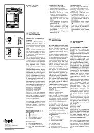
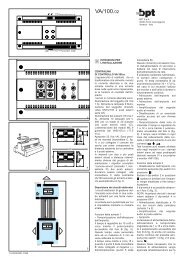
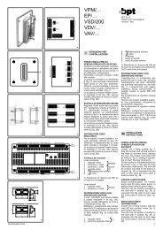
Function of connector CN1 (fig. 1)<br />
Connector CN1 features the output<br />
of the X1 bus and of the +24V DC<br />
power supply available for future<br />
applications.<br />
Note. The system is operative 1<br />
min after the system has been<br />
powered.<br />
Function of each terminal (fig. 1)<br />
Terminal block A<br />
mains<br />
Terminal block M1<br />
B IN bus line input<br />
Terminal block M2<br />
B OUT bus line output<br />
personal door bell<br />
– ground<br />
PROGRAMMING<br />
WARNING. Programming of<br />
receivers must only be carried<br />
out according to the following<br />
procedure:<br />
A) Program all receivers from the<br />
entry panel and ONLY AFTER-<br />
WARDS<br />
B) Carry out programming of the<br />
<strong>VSE</strong>/<strong>301</strong>.<br />
To carry out programming as in<br />
point A follow the instructions attached<br />
to the XA/300LR power supplier<br />
and to the X2 series entry<br />
panels.<br />
Programming the <strong>VSE</strong>/<strong>301</strong><br />
The selector <strong>VSE</strong>/<strong>301</strong> programming<br />
procedure must be performed<br />
once you have programmed<br />
which calls from the entry panels<br />
are to be associated with which<br />
receivers.<br />
1- Set selector <strong>VSE</strong>/<strong>301</strong> to programming<br />
mode by removing jumper<br />
SW1 (fig. 1);<br />
2- Select the receiver that you wish<br />
to program and press the intercommunicating<br />
call button, which<br />
you wish to use for calling.<br />
The receiver emits a sound three<br />
times to confirm programming has<br />
been completed successfully.<br />
3- Repeat the procedure described<br />
in point 2 for all receivers. If there<br />
aren’t any non-intercom receivers,<br />
the selector must be advised<br />
accordingly by pressing button<br />
Aux 2 (no confirmation tone).<br />
4- Exit programming by refitting<br />
jumper SW1.<br />
WARNING. For installations with<br />
XA/300LR, we recommend that you<br />
make a note of the receiver ID (SN)<br />
identification codes, attached to the<br />
outside of the casing, and write<br />
them in the tables attached to the<br />
XA/300LR, MPP/300LR and<br />
IPC/300LR appliances.<br />
Adding or replacing a receiver<br />
When wanting to add or replace a<br />
receiver to/in the installation, proceed<br />
as described in points 1 and<br />
4 of the “Programming the<br />
<strong>VSE</strong>/<strong>301</strong>” section.<br />
Technical features<br />
• Supply voltage: 230V AC 50/60<br />
Hz, +6% –10%.<br />
The transformer is electronically<br />
protected against overloading<br />
and short circuiting i.e. no fuses<br />
are used.<br />
• Power demand: 45 VA.<br />
• Receiver power supply through<br />
bus: 20 VDC (terminal block M2).<br />
• The <strong>VSE</strong>/<strong>301</strong> unit, on its own,<br />
can supply:<br />
- 1 intercom receiver and 9 on<br />
standby;<br />
• Number of receivers that can be<br />
activated by the same call: 10 (if<br />
monitors, power 9 of them with<br />
local supply).<br />
• Line transmitting towards receivers:<br />
nonpolarized twisted pair<br />
(Z = 100 Ω).<br />
• Line connecting to main line: non<br />
polarized twisted pair (Z = 100<br />
Ω).<br />
• Doorbell: continuous 3 s ring.<br />
• Intercom call note duration: 30 s.<br />
• Maximum distances: 100 m<br />
between selector and last receiver<br />
connected to the system<br />
(with cable VCM/1D).<br />
• Maximum number of selectors in<br />
a system 300 installation<br />
(XA/300LR): 100.<br />
• Maximum number of selectors in<br />
a system X2 installation: 25.<br />
• Working temperature range: 0 °C<br />
to +35 °C.<br />
• Dimensions: low-profile 8-unit<br />
module for installation on DIN rail<br />
(fig. 2).<br />
The unit can be installed, without<br />
terminal covers, in boxes featuring<br />
DIN rails (EN 50022).