System Heat Pump Outdoor Unit - MegaFrio
System Heat Pump Outdoor Unit - MegaFrio System Heat Pump Outdoor Unit - MegaFrio
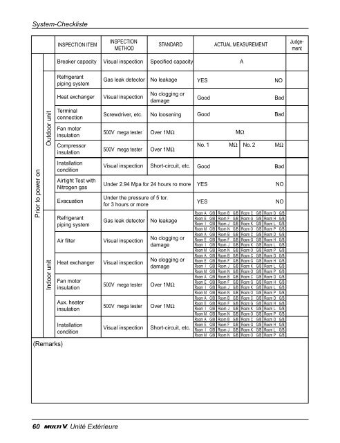
System-Checkliste Prior to power on Outdoor unit Indoor unit (Remarks) INSPECTION ITEM Breaker capacity Visual inspection Specified capacity Refrigerant piping system Air filter Visual inspection 60 Unité Extérieure Gas leak detector No leakage Heat exchanger Visual inspection Terminal connection Fan motor insulation Compressor insulation Installation condition Airtight Test with Nitrogen gas Evacuation Refrigerant piping system Heat exchanger Visual inspection Fan motor insulation Aux. heater insulation Installation condition INSPECTION METHOD No clogging or damage Screwdriver, etc. No loosening Good 500V mega tester Over 1MΩ 500V mega tester Over 1MΩ Visual inspection Short-circuit, etc. Under 2.94 Mpa for 24 hours ro more Under the pressure of 5 tor. for 3 hours or more Gas leak detector No leakage No clogging or damage No clogging or damage 500V mega tester Over 1MΩ 500V mega tester Over 1MΩ Visual inspection Short-circuit, etc. STANDARD ACTUAL MEASUREMENT YES NO Good Bad No. 1 Good MΩ Bad MΩ No. 2 MΩ Bad YES NO YES NO Room A G/B Room B G/B Room C G/B Room D G/B Room E G/B Room F G/B Room G G/B Room H G/B Room I G/B Room J G/B Room K G/B Room L G/B Room M G/B Room N G/B Room O G/B Room P G/B Room A G/B Room B G/B Room C G/B Room D G/B Room E G/B Room F G/B Room G G/B Room H G/B Room I G/B Room J G/B Room K G/B Room L G/B Room M G/B Room N G/B Room O G/B Room P G/B Room A G/B Room B G/B Room C G/B Room D G/B Room E G/B Room F G/B Room G G/B Room H G/B Room I G/B Room J G/B Room K G/B Room L G/B Room M G/B Room N G/B Room O G/B Room P G/B Room A G/B Room B G/B Room C G/B Room D G/B Room E G/B Room F G/B Room G G/B Room H G/B Room I G/B Room J G/B Room K G/B Room L G/B Room M G/B Room N G/B Room O G/B Room P G/B Room A G/B Room B G/B Room C G/B Room D G/B Room E G/B Room F G/B Room G G/B Room H G/B Room I G/B Room J G/B Room K G/B Room L G/B Room M G/B Room N G/B Room O G/B Room P G/B Room A G/B Room B G/B Room C G/B Room D G/B Room E G/B Room F G/B Room G G/B Room H G/B Room I G/B Room J G/B Room K G/B Room L G/B Room M G/B Room N G/B Room O G/B Room P G/B A Judgement
Prior to power on Outdoor unit Indoor unit (Remarks) INSPECTION ITEM INSPECTION METHOD Main power source voltage Tester Operation circuit voltage Tester Fan rotation direction Visual inspection Fan noise and vibration Listen and touch Fan operating current Clamp meter Inter air temperature Thermometer Outlet air temperature Thermometer Compressor suction pressure Pressure gauge Compressor charge pressure Pressure gauge Compressor rating current Clamp meter Compressor frequency Suction pipe temperature Discharge pipe temperature LED display Crankcase heater Touch by hand. Airtight Test with Nitrogen gas Evacuation Power source voltage Inlet air temperature Outlet air temperature Fan rotation direction Fan noise and vibration Fan operating current STANDARD ACTUAL MEASUREMENT ±10% of rated voltage ±10% of rated voltage Positive direction Temp. difference At cooling: 9-11°C At heating: 2-3.5°C ±10% of rated voltage Temp. difference At cooling: 9-13°C At heating: 15-20°C V V A °C °C System-Checkliste Good Bad kg/cm INVERTER 2 kg/cm2 Standard kg/cm INVERTER 2 kg/cm2 Standard Thermometer 3-15°C No. °C No. °C Thermometer 85-105°C No. Tester Thermometer Thermometer Visual inspection Should be heated. Under 2.94 Mpa for 24 hours ro more Under the pressure of 5 tor. for 3 hours or more Right direction Listen and touch – Clamp meter None Good Bad – INVERTER INV Hz A A Standard °C No. °C No. 1 Good Bad No. 1 Good Bad YES NO YES NO Room A G/B Room B G/B Room C G/B Room D G/B Room E G/B Room F G/B Room G G/B Room H G/B Room I G/B Room J G/B Room K G/B Room L G/B Room M G/B Room N G/B Room O G/B Room P G/B Room A G/B Room B G/B Room C G/B Room D G/B Room E G/B Room F G/B Room G G/B Room H G/B Room I G/B Room J G/B Room K G/B Room L G/B Room M G/B Room N G/B Room O G/B Room P G/B Room A G/B Room B G/B Room C G/B Room D G/B Room E G/B Room F G/B Room G G/B Room H G/B Room I G/B Room J G/B Room K G/B Room L G/B Room M G/B Room N G/B Room O G/B Room P G/B Room A G/B Room B G/B Room C G/B Room D G/B Room E G/B Room F G/B Room G G/B Room H G/B Room I G/B Room J G/B Room K G/B Room L G/B Room M G/B Room N G/B Room O G/B Room P G/B Room A G/B Room B G/B Room C G/B Room D G/B Room E G/B Room F G/B Room G G/B Room H G/B Room I G/B Room J G/B Room K G/B Room L G/B Room M G/B Room N G/B Room O G/B Room P G/B Room A G/B Room B G/B Room C G/B Room D G/B Room E G/B Room F G/B Room G G/B Room H G/B Room I G/B Room J G/B Room K G/B Room L G/B Room M G/B Room N G/B Room O G/B Room P G/B Judgement Montageanleitung 61 DEUTSCH
- Page 257 and 258: Vor der Ausführung des Probelaufs
- Page 259 and 260: Kombination mit Innengeräten Kombi
- Page 261 and 262: Erforderlicher Platzbedarf Individu
- Page 263 and 264: Gemeinsame Installation und Reiheni
- Page 265 and 266: Installation Position der Verankeru
- Page 267 and 268: Verlegung der Kälteleitungen A A A
- Page 269 and 270: Verlegung der Kälteleitungen ◆ R
- Page 271 and 272: ◆ Verteileranschluss CRUN458S0 Be
- Page 273 and 274: ◆ Reihen- / Verteileranschluss CR
- Page 275 and 276: ◆ Anschlussleitung Inneneinheit 5
- Page 277 and 278: Montage eines Abzweigs A A Verbindu
- Page 279 and 280: Dichtigkeitsprüfung und Evakuierun
- Page 281 and 282: Elektroarbeiten Vorsicht TB6 TB6 TB
- Page 283 and 284: Steuer- und Versorgungsleitungen 1)
- Page 285 and 286: ◆ Beispielanschluss der Steuerlei
- Page 287 and 288: ◆ Prozedur der automatischen Adre
- Page 289 and 290: Inneneinheit ID Drehschalter Klemme
- Page 291 and 292: ◆ Position des Drehschalters an d
- Page 293 and 294: 1 2 3 4 5 Probelauf Prüfungen vor
- Page 295 and 296: Selbstdiagnose-Funktion Fehleranzei
- Page 297 and 298: Position der LED01Y auf der Inverte
- Page 299 and 300: Rohrleitungsdiagramm CRUN458S0 4way
- Page 301 and 302: Vorbereitung der Leitungen Anhang D
- Page 303 and 304: WÄRMEDÄMMUNG Anhang 1. Verwenden
- Page 305 and 306: 3) Kondensatgrundleitung Anhang a)
- Page 307: Indoor unit A B C D E F G H I J K L
- Page 311 and 312: Ar Condicionado Multi V Unidade Ext
- Page 313 and 314: Precauções de segurança Precauç
- Page 315 and 316: Instale o ar condicionado de acordo
- Page 317 and 318: Não instale a unidade exterior, ne
- Page 319 and 320: Precauções antes do teste de ensa
- Page 321 and 322: Combinação com unidades interiore
- Page 323 and 324: Espaço necessário à volta da uni
- Page 325 and 326: Instalação colectiva e instalaç
- Page 327 and 328: Instalação Localização da cavil
- Page 329 and 330: A B Instalação da tubagem de refr
- Page 331 and 332: Sistema da tubagem de refrigeraçã
- Page 333 and 334: ◆ Método de cabeçalho de ramal
- Page 335 and 336: ◆ Método de linha/ cabeçalho de
- Page 337 and 338: ◆ Tubo de conexão da unidade int
- Page 339 and 340: A Como instalar o tubo de ramal A J
- Page 341 and 342: Teste de fechamento hermético e de
- Page 343 and 344: Ligações eléctricas Áreas de Pr
- Page 345 and 346: Linhas de transmissão e eléctrica
- Page 347 and 348: ◆ Exemplo da conexão do fio de t
- Page 349 and 350: ◆ Procedimento para direccionamen
- Page 351 and 352: Configuração do número de grupo
- Page 353 and 354: ◆ Posição do interruptor rotati
- Page 355 and 356: 1 2 3 4 5 Período de Testes Verifi
- Page 357 and 358: Função de auto-diagnóstico Indic
<strong>System</strong>-Checkliste<br />
Prior to power on<br />
<strong>Outdoor</strong> unit<br />
Indoor unit<br />
(Remarks)<br />
INSPECTION ITEM<br />
Breaker capacity Visual inspection Specified capacity<br />
Refrigerant<br />
piping system<br />
Air filter Visual inspection<br />
60 <strong>Unit</strong>é Extérieure<br />
Gas leak detector No leakage<br />
<strong>Heat</strong> exchanger Visual inspection<br />
Terminal<br />
connection<br />
Fan motor<br />
insulation<br />
Compressor<br />
insulation<br />
Installation<br />
condition<br />
Airtight Test with<br />
Nitrogen gas<br />
Evacuation<br />
Refrigerant<br />
piping system<br />
<strong>Heat</strong> exchanger Visual inspection<br />
Fan motor<br />
insulation<br />
Aux. heater<br />
insulation<br />
Installation<br />
condition<br />
INSPECTION<br />
METHOD<br />
No clogging or<br />
damage<br />
Screwdriver, etc. No loosening Good<br />
500V mega tester Over 1MΩ<br />
500V mega tester Over 1MΩ<br />
Visual inspection Short-circuit, etc.<br />
Under 2.94 Mpa for 24 hours ro more<br />
Under the pressure of 5 tor.<br />
for 3 hours or more<br />
Gas leak detector No leakage<br />
No clogging or<br />
damage<br />
No clogging or<br />
damage<br />
500V mega tester Over 1MΩ<br />
500V mega tester Over 1MΩ<br />
Visual inspection Short-circuit, etc.<br />
STANDARD ACTUAL MEASUREMENT<br />
YES NO<br />
Good Bad<br />
No. 1<br />
Good<br />
MΩ<br />
Bad<br />
MΩ No. 2 MΩ<br />
Bad<br />
YES NO<br />
YES NO<br />
Room A G/B Room B G/B Room C G/B Room D G/B<br />
Room E G/B Room F G/B Room G G/B Room H G/B<br />
Room I G/B Room J G/B Room K G/B Room L G/B<br />
Room M G/B Room N G/B Room O G/B Room P G/B<br />
Room A G/B Room B G/B Room C G/B Room D G/B<br />
Room E G/B Room F G/B Room G G/B Room H G/B<br />
Room I G/B Room J G/B Room K G/B Room L G/B<br />
Room M G/B Room N G/B Room O G/B Room P G/B<br />
Room A G/B Room B G/B Room C G/B Room D G/B<br />
Room E G/B Room F G/B Room G G/B Room H G/B<br />
Room I G/B Room J G/B Room K G/B Room L G/B<br />
Room M G/B Room N G/B Room O G/B Room P G/B<br />
Room A G/B Room B G/B Room C G/B Room D G/B<br />
Room E G/B Room F G/B Room G G/B Room H G/B<br />
Room I G/B Room J G/B Room K G/B Room L G/B<br />
Room M G/B Room N G/B Room O G/B Room P G/B<br />
Room A G/B Room B G/B Room C G/B Room D G/B<br />
Room E G/B Room F G/B Room G G/B Room H G/B<br />
Room I G/B Room J G/B Room K G/B Room L G/B<br />
Room M G/B Room N G/B Room O G/B Room P G/B<br />
Room A G/B Room B G/B Room C G/B Room D G/B<br />
Room E G/B Room F G/B Room G G/B Room H G/B<br />
Room I G/B Room J G/B Room K G/B Room L G/B<br />
Room M G/B Room N G/B Room O G/B Room P G/B<br />
A<br />
Judgement


