Cap´ıtulo 3 Modelado de Convertidores Estáticos de Potencia (CEP)
Cap´ıtulo 3 Modelado de Convertidores Estáticos de Potencia (CEP)
Cap´ıtulo 3 Modelado de Convertidores Estáticos de Potencia (CEP)

You also want an ePaper? Increase the reach of your titles
YUMPU automatically turns print PDFs into web optimized ePapers that Google loves.
CAPÍTULO3. MODELADODECONVERTIDORESESTÁTICOSDEPOTENCIA(<strong>CEP</strong>)30<br />
C a r g a<br />
F i l t r o L - C<br />
C<br />
L<br />
C o n v e r t i d o r<br />
M u l t i n i v e l<br />
V a<br />
n<br />
+<br />
_<br />
+<br />
_<br />
+<br />
_<br />
S 1<br />
V a 3<br />
V a 2<br />
V a 1<br />
S 2<br />
S 3 S 4<br />
S 1<br />
S 2<br />
S 3 S 4<br />
S 1<br />
S 2<br />
S 3 S 4<br />
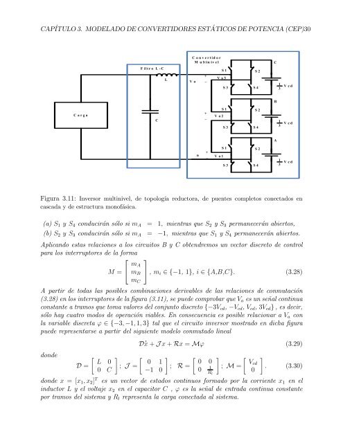
Figura 3.11: Inversor multinivel, <strong>de</strong> topología reductora, <strong>de</strong> puentes completos conectados en<br />
cascaday<strong>de</strong>estructuramonofásica.<br />
(a)S1 y S4 conduciránsólosimA = 1, mientrasqueS2 yS3 permaneceránabiertos,<br />
(b)S2 y S3 conduciránsólosimA = −1, mientrasqueS1 yS4 permaneceránabiertos.<br />
Aplicando estas relaciones a los circuitos B y C obtendremos un vector discreto <strong>de</strong> control<br />
paralosinterruptores<strong>de</strong>laforma<br />
⎡ ⎤<br />
M=<br />
⎣ mA<br />
mB<br />
mC<br />
C<br />
B<br />
A<br />
1<br />
3<br />
1<br />
3<br />
1<br />
3<br />
V c d<br />
V c d<br />
V c d<br />
⎦,mi∈{−1,1},i∈{A,B,C}. (3.28)<br />
A partir <strong>de</strong> todas las posibles combinaciones <strong>de</strong>rivables <strong>de</strong> las relaciones <strong>de</strong> conmutación<br />
(3.28)enlosinterruptores<strong>de</strong>lafigura(3.11),sepue<strong>de</strong>comprobarqueVaesunseñalcontinua<br />
constanteatramosquetomavalores<strong>de</strong>lconjuntodiscreto{−3Vcd,−Vcd,Vcd,3Vcd},es<strong>de</strong>cir,<br />
sólohaycuatromodos<strong>de</strong>operaciónviables.EnconsecuenciaesposiblerelacionaraVa con<br />
lavariable discretaϕ∈{−3,−1,1,3}tal queel circuitoinversormostrado en dicha figura<br />
pue<strong>de</strong>representarseapartir<strong>de</strong>lsiguientemo<strong>de</strong>loconmutadolineal<br />
don<strong>de</strong><br />
D=<br />
L 0<br />
0 C<br />
D x+Jx+Rx=Mϕ (3.29)<br />
<br />
0 1<br />
; J =<br />
−1 0<br />
<br />
0 0<br />
; R= 1 0 Rl<br />
<br />
Vcd<br />
; M=<br />
0<br />
<br />
. (3.30)<br />
don<strong>de</strong> x = [x1,x2] T es un vector <strong>de</strong> estados continuos formado por la corriente x1 en el<br />
inductor L y el voltaje x2 en el capacitor C , ϕ es la señal <strong>de</strong> entrada continua constante<br />
portramos<strong>de</strong>lsistemayRl representalacargaconectadaalsistema.