Cap´ıtulo 3 Modelado de Convertidores Estáticos de Potencia (CEP)
Cap´ıtulo 3 Modelado de Convertidores Estáticos de Potencia (CEP)
Cap´ıtulo 3 Modelado de Convertidores Estáticos de Potencia (CEP)

Create successful ePaper yourself
Turn your PDF publications into a flip-book with our unique Google optimized e-Paper software.
CAPÍTULO3. MODELADODECONVERTIDORESESTÁTICOSDEPOTENCIA(<strong>CEP</strong>)11<br />
+<br />
_ Ve(t)<br />
S<br />
1<br />
S<br />
2<br />
+<br />
u(t)<br />
_<br />
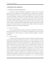
Figura3.1:Esquemabásico<strong>de</strong>unconvertidorestático<strong>de</strong>potencia<strong>de</strong>topologíareductora.<br />
3.1. Consi<strong>de</strong>racionesGenerales<br />
Debidoaquelaenergíaeléctricapue<strong>de</strong>sersuministradamedianteseñales<strong>de</strong>CAyCD,<br />
entendiendoporCAaaquellasseñales<strong>de</strong>voltajenominalmente<strong>de</strong>formasinusoidalyporCD<br />
aaquellasseñales<strong>de</strong>voltajequesonconstanteseneltiempo.Existencuatrofamiliasbásicas<br />
<strong>de</strong><strong>CEP</strong>:losconvertidores<strong>de</strong>CA/CDoreguladores,losconvertidoresCD/CAoconvertidores<br />
inversores,losconvertidoresCD/CDotroceadoresylosconvertidoresCA/CAovariadores<strong>de</strong><br />
frecuencia.Enestaclase<strong>de</strong>convertidoresloselementosconmutadoresconformanuncircuito<br />
eléctricocuyaestructurasevemodificadaconcadacambioenelestado<strong>de</strong>losinterruptores.<br />
Porello,estossistemaseléctricosposeenunadinámicaconmutadagobernadaúnicamentea<br />
través<strong>de</strong> señales<strong>de</strong> comando que habilitanlosestados<strong>de</strong> conducciónonoconducción<strong>de</strong><br />
cadauno<strong>de</strong>losdispositivosconmutadoresqueloscomponen.Enesesentido,ycomoprimer<br />
pasoparasucontrol,esnecesarioconstruirunmo<strong>de</strong>lomatemáticoquepermitacapturarla<br />
discontinuidadafin<strong>de</strong>po<strong>de</strong>rdarinicioacualquierestudio.<br />
Losdispositivosconmutadoresqueseránconsi<strong>de</strong>radossoninterruptoreselectrónicosi<strong>de</strong>a-<br />
les que pue<strong>de</strong>n adoptar dos estados en función <strong>de</strong> una señal <strong>de</strong> voltaje <strong>de</strong> comando Vg(t):<br />
elestado<strong>de</strong>conducción (o<strong>de</strong>encendido)cuandoelvoltajese<strong>de</strong>finacomoVg(t)=V on<br />
g yel<br />
estado<strong>de</strong>nocondución(o<strong>de</strong>apagado)siVg(t)=V off<br />
g ,don<strong>de</strong>V on<br />
g yV off<br />
g sonseñalescuyos<br />
niveles<strong>de</strong>voltaje<strong>de</strong>pen<strong>de</strong>n<strong>de</strong>ltipo<strong>de</strong>dispositivoconmutadorconsi<strong>de</strong>rado,porejemplolos<br />
dispositivosMOSFETpue<strong>de</strong>nseractivadosmedianteunaseñal<strong>de</strong>voltaje<strong>de</strong>compuertaque<br />
pue<strong>de</strong>ir<strong>de</strong>los5alos20volts,entantoqueelestado<strong>de</strong>noconducciónpue<strong>de</strong>activarseconun<br />
nivel<strong>de</strong>voltaje<strong>de</strong>cerovolts.Entonces,elestado<strong>de</strong>cadauno<strong>de</strong>estosinterruptorespue<strong>de</strong><br />
serrelacionadoconunavariable<strong>de</strong>naturalezadiscretaϕ.Porejemplo,consi<strong>de</strong>reel<strong>CEP</strong><strong>de</strong><br />
topologíareductoramostradoenlafigura3.1,elcualconsta<strong>de</strong>doselementosinterruptores<br />
i<strong>de</strong>alesS1yS2.Silosestados<strong>de</strong>losinterruptoresS1yS2son<strong>de</strong>finidosmediantelaaplicación<br />
<strong>de</strong> los voltajes<strong>de</strong> comando V g1 yV g2,respectivamente,entonces es posible agrupar dichos<br />
voltajesenunvector<strong>de</strong>laforma<br />
Vg(t)=<br />
Vg1<br />
V g2<br />
L<br />
<br />
C<br />
R