Cap´ıtulo 3 Modelado de Convertidores Estáticos de Potencia (CEP)
Cap´ıtulo 3 Modelado de Convertidores Estáticos de Potencia (CEP)
Cap´ıtulo 3 Modelado de Convertidores Estáticos de Potencia (CEP)

You also want an ePaper? Increase the reach of your titles
YUMPU automatically turns print PDFs into web optimized ePapers that Google loves.
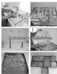
CAPÍTULO3. MODELADODECONVERTIDORESESTÁTICOSDEPOTENCIA(<strong>CEP</strong>)27<br />
Figura3.10:Convertidorregulador<strong>de</strong>corrientedirectaacorrientedirecta<strong>de</strong>topologíareductora.<br />
3.3.2. <strong>Mo<strong>de</strong>lado</strong><strong>de</strong>convertidores<strong>de</strong>CDaCD<br />
Los convertidores reguladores <strong>de</strong> voltaje <strong>de</strong> corriente directa a corriente directa (CD a<br />
CD),comoelmostradoenlafigura3.10,poseenunaampliavariedad<strong>de</strong>aplicacionestanto<br />
domésticascomo<strong>de</strong>laboratorioytelefonía.Enestasecciónsepresentaelmo<strong>de</strong>lo<strong>de</strong>dinámica<br />
conmutadaparaelconvertidorregulador<strong>de</strong>topologíareductora<strong>de</strong>lafigura3.10,elcualse<br />
compone<strong>de</strong>unarama<strong>de</strong>dosdispositivos<strong>de</strong>conmutación.<br />
Consi<strong>de</strong>requelosinterruptoresS1yS ′ 1sólopue<strong>de</strong>nserconmutados<strong>de</strong>maneracomplementaria,entoncesesposible<strong>de</strong>finirdosmodos<strong>de</strong>operaciónviablesy,<strong>de</strong>manerapráctica,<br />
un único voltaje <strong>de</strong> disparo. Nótese que el voltaje visto por el filtro pasivo y por la carga<br />
sólopue<strong>de</strong>serVe,paraS1cerrado,ó0enelcasoenqueS ′ 1conduzca.<br />
Mo<strong>de</strong>lo conmutado <strong>de</strong>l regulador <strong>de</strong> CD a CD Aplicando la misma filosofía <strong>de</strong><br />
mo<strong>de</strong>ladousadaenelcaso<strong>de</strong>linversor<strong>de</strong>mediopuente,esposiblellegaralasecuaciones<br />
mostradasenlatabla2,mediantelascuales,yconsi<strong>de</strong>randolacorrienteenelinductorL<br />
como el estado x1 y al voltaje en el capacitor C comola variable <strong>de</strong> estado x2, el mo<strong>de</strong>lo<br />
resultanteestádadopor<br />
L . x1 = −x2+Veϕ (3.25)<br />
C . x2 = x1− 1<br />
R x2.<br />
don<strong>de</strong>ϕ∈{0,1}.<br />
Considérese el mo<strong>de</strong>lo conmutado <strong>de</strong>l regulador <strong>de</strong> CD a CD (3.25) repetido a continuaciónconlaestructuradadaen(3.21)<br />
D x+Jx+Rx=Mϕ (3.26)