Protección Eléctrica de Instalaciones Catálogo (Europa) - Erico
Protección Eléctrica de Instalaciones Catálogo (Europa) - Erico
Protección Eléctrica de Instalaciones Catálogo (Europa) - Erico

Create successful ePaper yourself
Turn your PDF publications into a flip-book with our unique Google optimized e-Paper software.
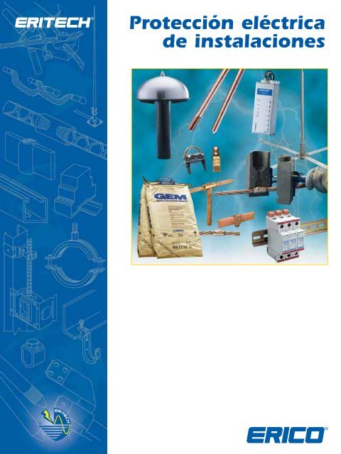
<strong>Protección</strong> eléctrica<br />
<strong>de</strong> instalaciones
PROTECCIÓN ELÉCTRICA DE INSTALACIONES<br />
Fundada en 1903 con el nombre <strong>de</strong> Electric Railway Improvement Company, ERICO ® <strong>de</strong>sarrolló el proceso <strong>de</strong> soldadura<br />
exotérmica CADWELD ® en 1938. Las conexiones CADWELD gozan <strong>de</strong> gran aceptación en todos el sector como los más<br />
avanzados contactos <strong>de</strong> empalme y puesta a tierra. Durante la década <strong>de</strong> 1970, ERICO fue pionera en electrodos para tierra <strong>de</strong><br />
acero revestidos <strong>de</strong> cobre. Hoy, la gama <strong>de</strong> productos <strong>de</strong> protección eléctrica <strong>de</strong> instalaciones <strong>de</strong> ERICO incluye los electrodos<br />
para tierra, los conectores y sistemas <strong>de</strong> tierra; material intensificador <strong>de</strong> tierra, medidores <strong>de</strong> puesta a tierra; protección<br />
estructural contra <strong>de</strong>scargas atmosféricas; alfombrillas y mallas <strong>de</strong> equipotencial, y re<strong>de</strong>s <strong>de</strong> referencia <strong>de</strong> señales ERITECH ® ;<br />
los sistemas <strong>de</strong> protección contra corrientes transitorias <strong>de</strong> baja tensión; y las conexiones exotérmicas CADWELD ® .<br />
<strong>Protección</strong> eléctrica <strong>de</strong> instalaciones<br />
La protección contra <strong>de</strong>scargas atmosféricas, los sistemas<br />
<strong>de</strong> puesta a tierra, los empalmes equipotenciales y<br />
la protección contra sobretensiones son todas disciplinas<br />
inter<strong>de</strong>pendientes en las que se especializa nuestro<br />
grupo <strong>de</strong> productos para la protección eléctrica <strong>de</strong><br />
instalaciones. Una protección fiable <strong>de</strong> personas y<br />
estructuras requiere un concepto sistemático y exhaustivo<br />
con el objeto <strong>de</strong> reducir al mínimo las amenazas <strong>de</strong><br />
las corrientes transitorias y<br />
otras perturbaciones <strong>de</strong>l<br />
sistema. Por ejemplo, ningún<br />
terminal aéreo pue<strong>de</strong> atraer y<br />
<strong>de</strong>sviar la energía <strong>de</strong> una<br />
<strong>de</strong>scarga atmosférica sin contar<br />
con una conexión fiable a<br />
tierra. Del mismo modo,<br />
incluso el más caro dispositivo<br />
<strong>de</strong> protección contra sobretensiones<br />
no podrá ofrecer una<br />
protección óptima si no<br />
hay instalada una conexión<br />
eléctrica <strong>de</strong> baja impedancia a<br />
tierra. Por su parte, un sistema<br />
<strong>de</strong> puesta a tierra <strong>de</strong> baja<br />
impedancia pue<strong>de</strong> suponer<br />
riesgos <strong>de</strong> daños físicos y<br />
materiales si no hay una<br />
conexión equipotencial. Estas<br />
disciplinas inter<strong>de</strong>pendientes<br />
pue<strong>de</strong>n aplicarse <strong>de</strong>bidamente<br />
sólo analizando la instalación<br />
íntegra, y no únicamente una parte <strong>de</strong> la misma o<br />
<strong>de</strong>terminado equipo.<br />
Dado que ninguna tecnología individual pue<strong>de</strong> eliminar<br />
los efectos perjudiciales <strong>de</strong> las <strong>de</strong>scargas atmosféricas o<br />
<strong>de</strong> las sobretensiones transitorias inducidas, ERICO ha<br />
<strong>de</strong>sarrollado el Plan <strong>de</strong> <strong>Protección</strong> <strong>de</strong> Seis Puntos. El<br />
concepto sobre el que se basa este plan es un enfoque<br />
holístico y coordinado que abarca todos los aspectos <strong>de</strong><br />
una efectiva protección eléctrica <strong>de</strong> las instalaciones.<br />
Las seis disciplinas inter<strong>de</strong>pendientes que constituyen el plan <strong>de</strong><br />
protección son:<br />
1. Captar el rayo<br />
2. Conducir esta energía a tierra<br />
3. Disipar la energía en el sistema <strong>de</strong> tierra<br />
4. Conectar todos los puntos <strong>de</strong> tierra<br />
5. Proteger las líneas <strong>de</strong> alimentación <strong>de</strong> CA entrante<br />
6. Proteger los circuitos <strong>de</strong> datos y telecomunicaciones <strong>de</strong><br />
baja tensión<br />
<strong>Protección</strong><br />
eléctrica <strong>de</strong><br />
instalaciones<br />
En ERICO ofrecemos innovadores y<br />
eficientes productos <strong>de</strong> empalme y puesta<br />
a tierra, avalados por una amplia<br />
experiencia <strong>de</strong> diseño y asistencia técnica.<br />
Gracias a esta experiencia, ERICO es lí<strong>de</strong>r<br />
mundial en el diseño y construcción <strong>de</strong><br />
sistemas <strong>de</strong> puesta a tierra <strong>de</strong> baja<br />
impedancia permanentes.<br />
ERICO aplica un programa <strong>de</strong> control<br />
<strong>de</strong> calidad para garantizar que los<br />
procedimientos <strong>de</strong>tallados necesarios para<br />
cada paso <strong>de</strong> la operación brin<strong>de</strong>n a<br />
nuestros clientes el mejor sistema posible.<br />
Esta atención a los <strong>de</strong>talles abarca <strong>de</strong>s<strong>de</strong><br />
el diseño y la adquisición <strong>de</strong> materiales<br />
hasta la fabricación, la instalación y la<br />
comprobación.<br />
Nuestra capacidad <strong>de</strong> I+D permite la<br />
mejora continua <strong>de</strong> los diseños con<br />
productos nuevos y perfeccionados que<br />
se anticipan a los rigurosos requisitos<br />
<strong>de</strong> las aplicaciones <strong>de</strong> un sector en continua evolución.<br />
La especialización en ingeniería la compartimos con todas<br />
las <strong>de</strong>más empresas <strong>de</strong> ERICO dispersas por el mundo,<br />
gracias a lo cual contamos con una amplia base <strong>de</strong><br />
conocimientos global.<br />
Confíe en ERICO para todas sus necesida<strong>de</strong>s <strong>de</strong> protección<br />
eléctrica <strong>de</strong> instalaciones.<br />
www.erico.com
PROTECCIÓN ELÉCTRICA DE INSTALACIONES<br />
www.erico.com<br />
Tabla <strong>de</strong> contenidos<br />
Información técnica ..........................................................................................Páginas 4-16<br />
<strong>Protección</strong> contra los rayos ........................................................................Páginas 17-29<br />
Conductores ......................................................................................................Páginas 30-32<br />
Sistemas <strong>de</strong> puesta a tierra y empalme................................................Páginas 33-43<br />
<strong>Protección</strong> contra sobretensiones............................................................Páginas 44-46<br />
CADWELD ® /CADWELD ® PLUS/CADWELD ® MULTI ................Páginas 47-57<br />
Índice ....................................................................................................................Páginas 58-59<br />
1
INTRODUCCIÓN AL CATÁLOGO<br />
PROTECCIÓN CONTRA<br />
DESCARGAS ATMOSFÉRICAS<br />
Punto 1 - Captar la<br />
<strong>de</strong>scarga eléctrica<br />
PÁGINAS 17 A 19<br />
PÁGINAS 21 A 22<br />
Punto 2 - Conducir esta<br />
energía hacia tierra<br />
PÁGINAS 23 A 26<br />
PÁGINAS 28 A 30<br />
Plan <strong>de</strong> <strong>Protección</strong> <strong>de</strong> Seis Puntos <strong>de</strong> ERICO ®<br />
Una protección eficaz contra las <strong>de</strong>scargas atmosféricas supone<br />
la integración <strong>de</strong> diversos conceptos. ERICO ® utiliza el Plan <strong>de</strong><br />
<strong>Protección</strong> <strong>de</strong> Seis Puntos como práctica guía para garantizar el<br />
más alto nivel <strong>de</strong> seguridad <strong>de</strong> los sistemas.<br />
SISTEMAS DE PUESTA A TIERRA Y EMPALME<br />
Punto 3 - Disipar la energía en el sistema <strong>de</strong> tierra<br />
Punto 4 - Conectar todos los<br />
puntos <strong>de</strong> tierra<br />
PÁGINAS 31 A 37 PÁGINAS 38 A 41<br />
2 www.erico.com
INTRODUCCIÓN AL CATÁLOGO<br />
PROTECCIÓN CONTRA<br />
SOBRETENSIONES<br />
Punto 5 - <strong>Protección</strong> <strong>de</strong> las líneas<br />
<strong>de</strong> alimentación <strong>de</strong> CA entrante<br />
www.erico.com<br />
1<br />
2<br />
3<br />
Captar la <strong>de</strong>scarga eléctrica. La captación <strong>de</strong> la<br />
<strong>de</strong>scarga eléctrica <strong>de</strong>be realizarse hacia un punto<br />
<strong>de</strong> conexión conocido y preferencial empleando un<br />
sistema <strong>de</strong> terminal aéreo diseñado a tal efecto.<br />
Conducir esta energía hacia tierra. La energía<br />
<strong>de</strong>be conducirse a tierra a través <strong>de</strong> un conductor<br />
<strong>de</strong> bajada diseñado a tal efecto.<br />
Disipar la energía en el sistema <strong>de</strong> tierra.<br />
La energía <strong>de</strong>be disiparse en un sistema <strong>de</strong><br />
puesta a tierra <strong>de</strong> baja impedancia.<br />
Punto 6 - <strong>Protección</strong> <strong>de</strong> los circuitos <strong>de</strong><br />
datos y telecomunicaciones <strong>de</strong> baja tensión<br />
3<br />
4<br />
5<br />
6<br />
Conectar todos los puntos <strong>de</strong> tierra. Es necesario<br />
interconectar todos los puntos <strong>de</strong> tierra para ayudar a<br />
eliminar los retornos <strong>de</strong> tierra y crear una equipotencial.<br />
Proteger las líneas <strong>de</strong> alimentación <strong>de</strong> CA entrante.<br />
Deben protegerse los equipos contra sobretensiones y<br />
corrientes transitorias <strong>de</strong> las líneas eléctricas entrantes para<br />
ayudar a evitar averías y onerosos períodos <strong>de</strong> inactividad.<br />
Proteger los circuitos <strong>de</strong> datos y telecomunicaciones<br />
<strong>de</strong> baja tensión. Deben protegerse los equipos contra<br />
sobretensiones y corrientes transitorias <strong>de</strong> las líneas <strong>de</strong><br />
telecomunicaciones y <strong>de</strong> señales entrantes para ayudar<br />
a evitar averías y onerosos períodos <strong>de</strong> inactividad.<br />
CADWELD ® PLUS<br />
PÁGINAS 46 A 48<br />
CADWELD ®<br />
PÁGINAS 50 A 56<br />
CADWELD ® MULTI<br />
PÁGINAS 43 A 44 PÁGINAS 43 A 44 PÁGINA 49<br />
CADWELD PROTECCIÓN CONTRA SOBRETENSIONES SISTEMAS DE PUESTA A TIERRA Y EMPALME CONDUCTORES<br />
PROTECCIÓN CONTRA LOS RAYOS INFORMACIÓN TÉCNICA
INFORMACIÓN TÉCNICA<br />
INFORMACIÓN TÉCNICA<br />
ERITECH<br />
PROTECCIÓN DE ESTRUCTURAS<br />
CONTRA DESCARGAS ATMOSFÉRICAS<br />
® SYSTEM 3000<br />
Existen dos tipos <strong>de</strong> dispositivos para proteger estructuras contra<br />
<strong>de</strong>scargas atmosféricas: los convencionales, basados sólo en<br />
componentes pasivos (cobre, acero galvanizado...); y los sistemas<br />
<strong>de</strong> protección activa. Estos últimos están basados en<br />
conocimientos avanzados y en más <strong>de</strong> 15 años <strong>de</strong> experiencia.<br />
PROTECCIÓN ACTIVA<br />
¿EN QUÉ CONSISTE EL SISTEMA?<br />
El ERITECH ® SYSTEM 3000 es un sistema <strong>de</strong> protección contra los<br />
rayos técnicamente avanzado. Las características únicas <strong>de</strong> este<br />
sistema permiten alcanzar un alto nivel <strong>de</strong> rendimiento técnico y,<br />
por consiguiente, permiten una captación más fiable <strong>de</strong> las<br />
<strong>de</strong>scargas atmosféricas.<br />
El Pararrayos ERITECH ® DYNASPHERE ofrece un punto <strong>de</strong> captura<br />
preferencial <strong>de</strong> para las <strong>de</strong>scargas atmosféricas que, <strong>de</strong> otro modo,<br />
caerían sobre una estructura no protegida y/o su contenido, con<br />
los consiguientes daños. El ERITECH DYNASPHERE se conecta a un<br />
conductor <strong>de</strong> bajada ERITECH ® ERICORE y al sistema <strong>de</strong> tierra <strong>de</strong><br />
tal modo que constituyen un sistema totalmente integrado.<br />
NIVEL DE PROTECCIÓN<br />
Las <strong>de</strong>scargas eléctricas atmosféricas son un fenómeno estadístico que<br />
hace prácticamente imposible conseguir una protección <strong>de</strong>l 100%,<br />
lo cual, por cierto, no sería económicamente práctico. La norma IEC<br />
62305-3 <strong>de</strong>fine 4 niveles <strong>de</strong> protección, conjuntamente con sus eficacias<br />
<strong>de</strong> intercepción asociadas. Esta información se utiliza para <strong>de</strong>terminar la<br />
ubicación y espaciado a<strong>de</strong>cuados <strong>de</strong> los terminales aéreos.<br />
NIVEL I 99% Estructuras <strong>de</strong> muy alto riesgo<br />
NIVEL II 97% Estructuras <strong>de</strong> alto riesgo<br />
NIVEL III 91% Estructuras <strong>de</strong> mediano riesgo<br />
NIVEL IV 84% Estructuras <strong>de</strong> bajo riesgo; por ejemplo,<br />
resi<strong>de</strong>nciales<br />
PARARRAYOS<br />
EL PARARRAYOS ERITECH DYNASPHERE<br />
El ERITECH DYNASPHERE es un pararrayos <strong>de</strong> tecnología avanzada<br />
patentado.<br />
• No es radiactivo<br />
• No tiene alimentación externa<br />
• No tiene partes móviles<br />
• Reacciona dinámicamente al acercarse una <strong>de</strong>scarga <strong>de</strong>scen<strong>de</strong>nte.<br />
PRINCIPIOS DEL ERITECH DYNASPHERE<br />
Durante más <strong>de</strong> 200 años, los sistemas <strong>de</strong> protección contra<br />
<strong>de</strong>scargas eléctricas atmosféricas han sido objeto <strong>de</strong> mínimas<br />
mejoras.<br />
Los métodos mo<strong>de</strong>rnos <strong>de</strong> investigación y registro han permitido<br />
una mejor compresión <strong>de</strong>l proceso <strong>de</strong> <strong>de</strong>scargas eléctricas,<br />
consiguiéndose importantes avances en la simulación <strong>de</strong> las condiciones<br />
<strong>de</strong> los campos eléctricos <strong>de</strong> estos fenómenos.<br />
De los estudios recientes se han <strong>de</strong>rivado dos conceptos<br />
fundamentales en cuanto al proceso <strong>de</strong> captación <strong>de</strong> las<br />
<strong>de</strong>scargas atmosféricas y <strong>de</strong>l rendimiento <strong>de</strong>l pararrayos:<br />
1. Los pararrayos que generan un potente efecto corona (carga<br />
espacial) tien<strong>de</strong>n a ser menos eficientes en la intercepción <strong>de</strong><br />
la <strong>de</strong>scarga <strong>de</strong>scen<strong>de</strong>nte <strong>de</strong> un rayo.<br />
2. Se entien<strong>de</strong> por terminal aéreo óptimo a aquél que lanza un<br />
canal <strong>de</strong> recepción ascen<strong>de</strong>nte que tiene altas probabilida<strong>de</strong>s<br />
<strong>de</strong> convertirse en una <strong>de</strong>scarga estable en propagación (para<br />
interceptar la <strong>de</strong>scarga <strong>de</strong>scen<strong>de</strong>nte)<br />
El ERITECH DYNASPHERE ha sido <strong>de</strong>sarrollado consi<strong>de</strong>rando<br />
ambos conceptos.<br />
El ERITECH DYNASPHERE es una punta Franklin mejorada con una<br />
cúpula esférica acoplada capacitivamente al campo eléctrico <strong>de</strong><br />
una <strong>de</strong>scarga eléctrica que se aproxima a tierra.<br />
Esta superficie conductora esférica ro<strong>de</strong>a a un pararrayos central<br />
puesto a tierra. La esfera está aislada <strong>de</strong>l electrodo, auque<br />
conectada a tierra a través <strong>de</strong> una conducción <strong>de</strong> CC <strong>de</strong> alta<br />
impedancia.<br />
El ERITECH DYNASPHERE se aísla <strong>de</strong> la estructura mediante<br />
un mástil <strong>de</strong> soporte aislado. Este mástil también permite<br />
la conexión segura <strong>de</strong>l conductor <strong>de</strong> bajada ERITECH ERICORE<br />
al pararrayos.<br />
4 www.erico.com
INFORMACIÓN TÉCNICA<br />
www.erico.com<br />
RELLENO PLÁSTICO PARA INCREMENTAR EL<br />
DIÁMETRO EFECTIVO DEL CONDUCTOR<br />
CENTRAL (efecto pelicular <strong>de</strong> inductancia)<br />
CONDUCTOR PRINCIPAL<br />
CINTA DE COBRE<br />
CAPA SEMICONDUCTORA DE CONTROL DE<br />
CONTROL DE ESFUERZO<br />
PROTECCIÓN CONVENCIONAL<br />
La protección convencional <strong>de</strong> edificios o estructuras<br />
implica el uso <strong>de</strong> terminales aéreos (pararrayos)<br />
a<strong>de</strong>cuadamente ubicados, interconectados mediante<br />
una red <strong>de</strong> conductores <strong>de</strong> bajada metálicos<br />
(generalmente <strong>de</strong> cobre) para que sean la vía más<br />
directa <strong>de</strong>s<strong>de</strong> el terminal aéreo hasta el sistema<br />
<strong>de</strong> puesta a tierra <strong>de</strong> baja impedancia.<br />
Esto ayuda a garantizar una disipación segura<br />
y efectiva <strong>de</strong>l impulso <strong>de</strong> la <strong>de</strong>scarga atmosférica.<br />
Los sistemas convencionales suelen <strong>de</strong>nominarse<br />
jaula (o pantalla) Faraday.<br />
AISLAMIENTO DE ALTA TENSIÓN DE POLIETILENO<br />
CAPA SEMICONDUCTORA DE CONTROL DE ESFUERZO<br />
PANTALLA PRINCIPAL DE CINTA DE COBRE<br />
FUNDA EXTERIOR SEMICONDUCTORA<br />
ABRAZADERAS METÁLICAS PARA FIJAR EL<br />
CABLE Y LA PANTALLA EXTERIOR DE EMPALME<br />
A LA ESTRUCTURA<br />
ERITECH ® SYSTEM 1000<br />
ERITECH ® SYSTEM 2000<br />
5<br />
CARACTERÍSTICAS TÉCNICAS<br />
Y DE DISEÑO DEL<br />
ERITECH ® ERICORE<br />
Los conductores <strong>de</strong> bajada ERITECH ERICORE<br />
han sido diseñados para satisfacer los criterios<br />
<strong>de</strong> un conductor <strong>de</strong> bajada eficaz y fiable, con<br />
las siguientes características principales:<br />
• una baja inductancia por metro<br />
• una baja impedancia <strong>de</strong> sobretensiones<br />
• una distribución <strong>de</strong>l campo eléctrico inter<br />
no cuidadosamente controlada para minimizar<br />
los esfuerzos <strong>de</strong> campo bajo las condiciones <strong>de</strong><br />
los impulsos <strong>de</strong> corriente<br />
• un terminal superior cuidadosamente diseñado<br />
para reducir el esfuerzo<br />
TERMINALES AÉREOS ERITECH ® INTERCEPTOR SI ESE<br />
• Diseñados y probados según las normas NFC17-102 y UNE-21186<br />
• Diseño <strong>de</strong> acero inoxidable idóneo para la mayoría <strong>de</strong> los entornos<br />
• Disponibles en tres mo<strong>de</strong>los para adaptarse a los requisitos específicos <strong>de</strong> cada<br />
emplazamiento<br />
• Idóneos para la conexión a diversos sistemas <strong>de</strong> conductores <strong>de</strong> bajada, incluyendo cinta,<br />
cable, cable <strong>de</strong> bajada <strong>de</strong> pararrayos y conductores ERITECH ERICORE<br />
• Totalmente compatibles con los mástiles <strong>de</strong>l ERITECH ® SYSTEM 3000, el cable<br />
ERITECH ® ERICORE y accesorios<br />
Pararrayos Simple Jaula Faraday<br />
INFORMACIÓN TÉCNICA
INFORMACIÓN TÉCNICA<br />
INFORMACIÓN TÉCNICA<br />
Para el rendimiento eficaz <strong>de</strong> un sistema <strong>de</strong> protección contra<br />
<strong>de</strong>scargas atmosféricas, es esencial un sistema <strong>de</strong> tierra <strong>de</strong> baja<br />
impedancia que facilite la disipación <strong>de</strong> la energía <strong>de</strong>l rayo a<br />
masa. Debido a que las condiciones <strong>de</strong>l suelo y las características<br />
estacionales varían según el sitio, los métodos <strong>de</strong> puesta a tierra<br />
<strong>de</strong>ben ser consi<strong>de</strong>rados individualmente.<br />
ELECTRODOS, CINTAS Y<br />
CONECTORES DE TIERRA<br />
Los electrodos <strong>de</strong> puesta a tierra <strong>de</strong> acero inoxidable y<br />
galvanizado, revestidos <strong>de</strong> cobre, ERITECH ® facilitan la<br />
transferencia a tierra <strong>de</strong> sobretensiones y corrientes <strong>de</strong><br />
cortocircuito, caracterizándose también por su prolongada<br />
vida útil <strong>de</strong>bido a la alta calidad <strong>de</strong> su diseño y construcción.<br />
ENRIQUECEDOR DE TIERRA<br />
(GEM)<br />
El enriquecedor <strong>de</strong> tierra GEM pue<strong>de</strong> aplicarse a los conductores<br />
<strong>de</strong> un sistema <strong>de</strong> puesta a tierra para reducir la resistencia <strong>de</strong>l<br />
suelo local y la baja impedancia <strong>de</strong> tierra. Resulta especialmente<br />
práctico en áreas <strong>de</strong> humedad variable, así como en suelos<br />
arenosos y terrenos rocosos.<br />
EQUIPOTENCIALIDAD DE LOS<br />
CIRCUITOS DE TIERRA<br />
Las barras, placas, mallas prefabricadas y vías <strong>de</strong> chispa <strong>de</strong><br />
ERICO se combinan para crear un plano <strong>de</strong> tierra equipotencial<br />
seguro para la protección <strong>de</strong> personas y equipos.<br />
UNIÓN MOLECULAR<br />
CADWELD ® /CADWELD ® PLUS<br />
Las conexiones suelen ser el elemento más crítico <strong>de</strong> los<br />
sistemas <strong>de</strong> puesta a tierra y, en consecuencia, pue<strong>de</strong>n<br />
convertirse en su punto débil <strong>de</strong>bido al envejecimiento y<br />
corrosión. El método preferencial <strong>de</strong> conexión es el proceso<br />
<strong>de</strong> soldadura exotérmica CADWELD ® , capaz <strong>de</strong> producir una<br />
unión molecular permanente. La capacidad <strong>de</strong> un circuito<br />
<strong>de</strong> puesta a tierra <strong>de</strong> proteger la seguridad <strong>de</strong> las personas<br />
<strong>de</strong>pen<strong>de</strong>rá <strong>de</strong> la calidad <strong>de</strong> las conexiones realizadas.<br />
Cubierta<br />
polimérica<br />
Carga<br />
CADWELD PLUS<br />
Mol<strong>de</strong><br />
<strong>de</strong> grafito<br />
Conductor<br />
6 www.erico.com<br />
TAPA<br />
CRISOL<br />
POLVO DE<br />
IGNICIÓN<br />
CONDUCTOR<br />
Tira <strong>de</strong><br />
ignición<br />
Agujero <strong>de</strong><br />
colada<br />
Cámara <strong>de</strong><br />
soldadura<br />
El Mol<strong>de</strong> CADWELD<br />
METAL DE<br />
APORTE<br />
ASIENTO<br />
DEL<br />
DISCO<br />
AGUJERO<br />
DE<br />
COLADA<br />
CONDUCTOR<br />
CÁMARA<br />
DE<br />
SOLDADURA
INFORMACIÓN TÉCNICA<br />
ELECTRODOS DE TIERRA<br />
El electrodo <strong>de</strong> tierra es un componente fundamental <strong>de</strong>l sistema <strong>de</strong><br />
puesta a tierra. Existen diferentes tipos <strong>de</strong> electrodos, algunos<br />
“naturales” y otros “artificiales”. Entre los “naturales” merecen<br />
mencionarse los conductos <strong>de</strong> agua metálicos subterráneos, el<br />
encofrado metálico <strong>de</strong> un edificio (si es que su puesta a tierra es<br />
a<strong>de</strong>cuada), un cable <strong>de</strong> cobre o una barra <strong>de</strong> refuerzo en una base<br />
<strong>de</strong> hormigón o en las estructuras o sistemas subterráneos. Es<br />
necesario consi<strong>de</strong>rar la unión <strong>de</strong> los métodos <strong>de</strong> puesta a tierra<br />
“naturales” para asegurar una continuidad eléctrica con las otras<br />
“puestas a tierra” <strong>de</strong> las instalaciones.<br />
Los electrodos “artificiales” se instalan específicamente para mejorar<br />
la capacidad <strong>de</strong> puesta a tierra <strong>de</strong>l sistema. I<strong>de</strong>almente, para reducir<br />
la resistencia, estos electrodos <strong>de</strong>ben atravesar el nivel <strong>de</strong> humedad<br />
<strong>de</strong>bajo <strong>de</strong> la superficie <strong>de</strong>l suelo. Asimismo, <strong>de</strong>ben estar constituidos<br />
por conductores metálicos (o por una combinación <strong>de</strong> diversos<br />
conductores metálicos) que no se corroan excesivamente durante la<br />
vida útil <strong>de</strong> servicio prevista. Estos electrodos incluyen puntas o tubos<br />
enterrados, placas metálicas enterradas, o un anillo <strong>de</strong> cobre que<br />
ro<strong>de</strong>a la estructura. Los conductos subterráneos <strong>de</strong> gas y los<br />
electrodos <strong>de</strong> aluminio NO SE ADMITEN como electrodos <strong>de</strong> puesta<br />
a tierra.<br />
ELECTRODOS DE TIERRA<br />
¿Qué electrodo <strong>de</strong> tierra <strong>de</strong>be utilizarse?<br />
Los electrodos <strong>de</strong> tierra suelen seleccionarse en función <strong>de</strong> su resistencia<br />
a la corrosión. Otro factor importante es el coste. Muchas veces pue<strong>de</strong><br />
consi<strong>de</strong>rarse como tal el precio inicial <strong>de</strong> un producto, aunque el coste real<br />
está <strong>de</strong>terminado por la vida útil <strong>de</strong> servicio <strong>de</strong>l electrodo.<br />
Los electrodos <strong>de</strong> acero galvanizado son algunos <strong>de</strong> los más económicos<br />
que existen en el mercado. No obstante, su relación calidad-precio no es la<br />
óptima, ya que su vida útil es relativamente corta. Los electrodos <strong>de</strong> cobre<br />
y <strong>de</strong> acero inoxidable macizo tienen una prolongada vida útil. No obstante,<br />
son consi<strong>de</strong>rablemente más caros que los <strong>de</strong> acero galvanizado. A ello<br />
<strong>de</strong>be sumarse el hecho <strong>de</strong> que los electrodos <strong>de</strong> cobre macizo no son<br />
a<strong>de</strong>cuados para enterrarlos profundamente, o incluso<br />
una corta distancia, en terreno duro sin doblarse.<br />
Como solución <strong>de</strong> compromiso se <strong>de</strong>sarrollaron<br />
los electrodos <strong>de</strong> tierra <strong>de</strong> núcleo <strong>de</strong> acero,<br />
embutidos en una funda <strong>de</strong> cobre o <strong>de</strong> acero<br />
inoxidable. Estos electrodos son mucho más<br />
económicos que los macizos. Entre otras<br />
cosas, pue<strong>de</strong>n enterrarse a profundidad. No<br />
obstante, la cubierta <strong>de</strong> estos electrodos suele<br />
<strong>de</strong>sgastarse o <strong>de</strong>slizarse, en especial la <strong>de</strong> cobre.<br />
Una vez dañada esta funda, la integridad <strong>de</strong>l<br />
electrodo íntegro queda afectada.<br />
Solicite el documento “Ground Rods –<br />
Copperbon<strong>de</strong>d vs. Galvanized (Electrodos<br />
<strong>de</strong> tierra: Revestidos <strong>de</strong> cobre vs. galvanizados)<br />
<strong>de</strong> ERICO ® (en inglés).<br />
Comparativa <strong>de</strong> electrodos<br />
<strong>de</strong> tierra revestidos <strong>de</strong> cobre<br />
y galvanizados.<br />
www.erico.com 7<br />
ELECTRODO DE TIERRA<br />
REVESTIDO DE COBRE<br />
Prolongada vida útil<br />
con buena relación<br />
calidad-precio<br />
Revestimiento <strong>de</strong><br />
cobre:<br />
Unión molecular<br />
permanente<br />
Baja resistencia<br />
Alta capacidad para<br />
corrientes <strong>de</strong><br />
cortocircuito<br />
(Norma IEEE ® 80)<br />
No se <strong>de</strong>sliza ni<br />
<strong>de</strong>sgasta al instalar<br />
No se cuartea si el<br />
electrodo se tuerce<br />
Núcleo y punta <strong>de</strong><br />
acero al carbono:<br />
Mayor resistencia a<br />
la tracción<br />
Posibilidad <strong>de</strong><br />
enterramiento<br />
profundo<br />
ELECTRODO DE<br />
TIERRA GALVANIZADO<br />
Bajo precio <strong>de</strong><br />
compra, aunque su<br />
relación calidadprecio<br />
es inferior a<br />
la <strong>de</strong> los electrodos<br />
revestidos <strong>de</strong> cobre<br />
Revestimiento<br />
galvanizado:<br />
Vida útil <strong>de</strong> servicio<br />
relativamente corta<br />
Pue<strong>de</strong> cuartearse si<br />
el electrodo se tuerce<br />
Núcleo y punta<br />
<strong>de</strong> acero:<br />
Alta resistencia<br />
a la tracción<br />
Posibilidad <strong>de</strong><br />
enterramiento<br />
profundo<br />
INFORMACIÓN TÉCNICA
INFORMACIÓN TÉCNICA<br />
INFORMACIÓN TÉCNICA<br />
ELECTRODOS DE TIERRA<br />
Los electrodos revestidos <strong>de</strong> cobre<br />
tienen un revestimiento electrolítico<br />
<strong>de</strong> cobre <strong>de</strong>positado sobre una capa<br />
<strong>de</strong> níquel. Este proceso garantiza una<br />
unión molecular dura<strong>de</strong>ra entre la capa<br />
<strong>de</strong> cobre y el núcleo <strong>de</strong> acero. ERICO ®<br />
recomienda los electrodos <strong>de</strong> tierra<br />
revestidos <strong>de</strong> cobre porque este<br />
revestimiento no se <strong>de</strong>sliza ni se<br />
<strong>de</strong>sgasta al instalarlo, y porque no se<br />
cuartea si el electrodo se tuerce. El<br />
resistente núcleo <strong>de</strong> acero al carbono<br />
tiene excelentes características para su<br />
enterramiento. Los electrodos <strong>de</strong> tierra<br />
revestidos <strong>de</strong> cobre tienen una alta<br />
resistencia a la corrosión y constituyen<br />
una vía <strong>de</strong> baja resistencia a tierra.<br />
ESPERANZA DE VIDA DE ELECTRODOS DE TIERRA<br />
AÑOS<br />
Zinc<br />
galvanizado<br />
Acero revestido <strong>de</strong><br />
cobre (10 mil/254 µm)<br />
Acero revestido <strong>de</strong><br />
cobre (13 mil/330 µm)<br />
Las fotografías superiores muestran dos<br />
electrodos <strong>de</strong> tierra sometidos a la misma<br />
carga <strong>de</strong> presión. El electrodo <strong>de</strong> tierra<br />
revestido <strong>de</strong> cobre ERITECH ® , a la izquierda,<br />
se tuerce sin que la funda exterior se<br />
<strong>de</strong>sgarrare, cuartee ni pliegue. El electrodo<br />
chapado en cobre <strong>de</strong> calidad inferior <strong>de</strong> la<br />
<strong>de</strong>recha muestra fisuras y pliegues en su<br />
funda exterior, lo que reduce<br />
significativamente su vida útil <strong>de</strong> servicio y<br />
pone en riesgo la integridad <strong>de</strong>l electrodo.<br />
Acero<br />
inoxidable<br />
COSTE COMPARATIVO<br />
La opción <strong>de</strong> acero inoxidable<br />
Es importante <strong>de</strong>stacar que ciertos suelos y<br />
terraplenados pue<strong>de</strong>n no ser compatibles<br />
con el cobre. En tales circunstancias, el<br />
acero inoxidable es una mejor opción. El<br />
acero inoxidable también pue<strong>de</strong> ser una<br />
alternativa en los casos en que las<br />
estructuras o componentes, como torres<br />
<strong>de</strong> acero, postes o cables revestidos <strong>de</strong><br />
plomo, se hallan en las proximida<strong>de</strong>s <strong>de</strong><br />
un conjunto <strong>de</strong> electrodos <strong>de</strong> puesta a<br />
tierra. En tales circunstancias <strong>de</strong>ben<br />
consi<strong>de</strong>rarse los efectos <strong>de</strong> la corrosión<br />
galvánica. El alto coste <strong>de</strong> los electrodos<br />
<strong>de</strong> acero inoxidable hace prohibitivo su<br />
uso extendido.<br />
COSTE ANUAL DE ELECTRODOS DE TIERRA<br />
Zinc<br />
galvanizado<br />
Acero revestido <strong>de</strong><br />
cobre (10 mil/254 µm)<br />
Acero revestido <strong>de</strong><br />
cobre (13 mil/330 µm)<br />
Acero<br />
inoxidable<br />
8 www.erico.com
INFORMACIÓN TÉCNICA<br />
¿POR QUÉ ES IMPORTANTE UNA ADECUADA<br />
PUESTA A TIERRA?<br />
La naturalieza transitoria <strong>de</strong> las <strong>de</strong>scargas atmosféricas, con sus<br />
característicos rápidos tiempos <strong>de</strong> formación y corrientes <strong>de</strong> gran<br />
magnitud, implican la necesidad <strong>de</strong> una consi<strong>de</strong>ración especial a la puesta<br />
a tierra con el fin <strong>de</strong> que la protección sea efectiva. Existen muchos<br />
factores — como las variaciones en la resistencia específica <strong>de</strong> los suelos,<br />
la accesibilidad <strong>de</strong> la instalación, la disposición y las características físicas<br />
existentes — específicas <strong>de</strong> cada emplazamiento, y que afectan a la<br />
<strong>de</strong>cisión sobre cuál método <strong>de</strong> puesta a tierra emplear. El principal<br />
objetivo <strong>de</strong>l sistema <strong>de</strong> puesta a tierra <strong>de</strong> una <strong>de</strong>scarga directa es:<br />
• Disipar <strong>de</strong> manera eficiente la energía <strong>de</strong> la <strong>de</strong>scarga eléctrica a tierra<br />
• Contribuir a garantizar la seguridad <strong>de</strong> equipos y personas<br />
PRINCIPIOS DE LA PUESTA A TIERRA<br />
La clave <strong>de</strong> la protección contra las <strong>de</strong>scargas atmosféricas es la baja<br />
impedancia. Todas las conexiones <strong>de</strong> puesta a tierra <strong>de</strong>ben ser lo más<br />
cortas y breves posible para minimizar la inductancia y reducir los picos<br />
<strong>de</strong> tension inducidos en las conexiones. El sistema <strong>de</strong> electrodos <strong>de</strong><br />
tierra <strong>de</strong>be po<strong>de</strong>r tolerar <strong>de</strong> manera eficaz las sobretensiones <strong>de</strong> las<br />
<strong>de</strong>scargas y canalizarlas a tierra maximizando el acoplamiento capacitivo<br />
al suelo. Asimismo, <strong>de</strong>be minimizarse la resistencia <strong>de</strong> la propia tierra<br />
a las corrientes <strong>de</strong> la <strong>de</strong>scarga. Sólo tomando en cuenta estos factores<br />
pue<strong>de</strong> conseguirse una máxima protección contra estos fenómenos.<br />
IMPEDANCIA DE TIERRA<br />
La resistencia específica, o resistividad, <strong>de</strong>l suelo es una importante<br />
consi<strong>de</strong>ración para el diseño. La notable variación en función <strong>de</strong> los<br />
diferentes tipos <strong>de</strong> suelos, contenido <strong>de</strong> humedad y temperatura<br />
provoca variaciones en las impedancias <strong>de</strong> tierra.<br />
La Figura 1-B muestra la circulación <strong>de</strong> la corriente <strong>de</strong>s<strong>de</strong> el punto<br />
<strong>de</strong> inyección <strong>de</strong> un electrodo <strong>de</strong> tierra. A medida que la corriente fluye<br />
<strong>de</strong>s<strong>de</strong> el punto <strong>de</strong> inyección central, se produce un gradiente eléctrico<br />
en la superficie <strong>de</strong> tierra alre<strong>de</strong>dor <strong>de</strong>l electrodo. Este gradiente<br />
disminuye y se estabiliza a cierta distancia <strong>de</strong>l electrodo, como pue<strong>de</strong><br />
verse en la Figura 1-A. La impedancia observada en la corriente está<br />
<strong>de</strong>terminada por las partículas <strong>de</strong>l suelo en contacto directo con la<br />
superficie <strong>de</strong>l electrodo, así como por la impedancia general <strong>de</strong>l suelo.<br />
CONEXIONES A TIERRA CORTAS Y DIRECTAS<br />
La tensión generada por una <strong>de</strong>scarga atmosférica <strong>de</strong>pen<strong>de</strong><br />
fundamentalmente <strong>de</strong>l tiempo <strong>de</strong> formación <strong>de</strong> la corriente transitoria<br />
y <strong>de</strong> la impedancia (sobre todo la inductancia) <strong>de</strong>l trayecto a tierra. Los<br />
tiempos <strong>de</strong> formación extremadamente rápidos conllevan significativos<br />
incrementos <strong>de</strong> tensión como consecuencia a cualquier inductancia<br />
en serie resultante <strong>de</strong> trayectos largos e indirectos, o bien <strong>de</strong> curvas<br />
bruscas en el tendido <strong>de</strong> los conductores a tierra.<br />
ACOPLAMIENTO DEL SISTEMA DE<br />
ELECTRODOS A TIERRA<br />
La eficacia <strong>de</strong> un sistema <strong>de</strong> electrodos <strong>de</strong> puesta a tierra en acoplar<br />
la corriente <strong>de</strong> la <strong>de</strong>scarga a tierra <strong>de</strong>pen<strong>de</strong> <strong>de</strong> una serie <strong>de</strong> factores,<br />
entre ellos la geometría <strong>de</strong>l sistema <strong>de</strong> electrodos, la forma <strong>de</strong> los<br />
conductores y el acoplamiento efectivo al suelo.<br />
www.erico.com<br />
GEM<br />
Sistema <strong>de</strong> puesta a tierra típico.<br />
CONDUCTOR DE BAJADA<br />
ARQUETA DE<br />
INSPECCIÓN<br />
Fig.1-A<br />
Fig.1-B<br />
• Buena conductividad eléctrica<br />
• Conductores capaces <strong>de</strong> tolerar altas corrientes <strong>de</strong> cortocircuito<br />
• Prolongada vida útil (40 años como mínimo)<br />
• Baja resistencia e impedancia <strong>de</strong>l suelo<br />
9<br />
Electrodo <strong>de</strong> tierra<br />
CARACTERÍSTICAS DE UN BUEN SISTEMA<br />
DE PUESTA A TIERRA<br />
Cualquier instalación <strong>de</strong> puesta a tierra <strong>de</strong>be tener como principio<br />
intentar maximizar la superficie <strong>de</strong> contacto <strong>de</strong> los electrodos o<br />
conductores con el suelo circundante. Esto no sólo ayuda a reducir<br />
la resistencia <strong>de</strong>l suelo al sistema <strong>de</strong> puesta a tierra, sino que<br />
a<strong>de</strong>más incrementa significativamente la impedancia <strong>de</strong>l sistema<br />
en condiciones <strong>de</strong> <strong>de</strong>scargas atmosféricas.<br />
• Uniones equipotenciales<br />
Las Uniones equipotenciales ayudan a garantizar que no se<br />
produzcan diferencias potencialmente peligrosas entre tierra y<br />
los diferentes conductores <strong>de</strong> entrada, como conductos <strong>de</strong> agua<br />
metálicos, sistemas eléctricos y <strong>de</strong> comunicaciones. Asimismo,<br />
minimiza las tensiones <strong>de</strong> paso y <strong>de</strong> contacto.<br />
• Buena resistencia a la corrosión<br />
Distancia<br />
<strong>de</strong>s<strong>de</strong> el<br />
electrodo<br />
El sistema <strong>de</strong> electrodos <strong>de</strong> tierra <strong>de</strong>be ser resistente a la corrosión,<br />
y compatible con otros conductores enterrados y conectados al<br />
sistema. El cobre es, <strong>de</strong> lejos, el material más habitual utilizado en<br />
conductores <strong>de</strong> puesta a tierra. En general, <strong>de</strong>bería adoptarse algún<br />
procedimiento <strong>de</strong> mantenimiento o inspección para garantizar la<br />
eficacia a largo plazo <strong>de</strong>l sistema <strong>de</strong> puesta a tierra.<br />
• <strong>Eléctrica</strong> y mecánicamente sólido y fiable<br />
Pue<strong>de</strong> utilizarse un conector mecánico para unir los conductores<br />
a tierra, aunque este método sufre por los efectos <strong>de</strong> la corrosión<br />
si se utilizan metales diferentes. A<strong>de</strong>más <strong>de</strong> una gran soli<strong>de</strong>z<br />
mecánica, las conexiones CADWELD ® se caracterizan por una<br />
excelente baja impedancia, por su prolongada vida útil y su<br />
excelente resistencia a la corrosión.<br />
INFORMACIÓN TÉCNICA
INFORMACIÓN TÉCNICA<br />
INFORMACIÓN TÉCNICA<br />
COMPONENTES DE UN SISTEMA DE<br />
PUESTA A TIERRA<br />
Un sistema <strong>de</strong> puesta a tierra para la protección contra los rayos<br />
tiene por objeto llevar a tierra la corriente <strong>de</strong> éstas. Consta <strong>de</strong><br />
uno o más electrodos <strong>de</strong> puesta a tierra, y <strong>de</strong> los conductores<br />
<strong>de</strong> interconexión necesarios. Los componentes incluyen:<br />
• Electrodos <strong>de</strong> puesta a tierra<br />
• Materiales enriquecedores <strong>de</strong> tierra (GEM)<br />
• Conexiones soldadas exotérmicas CADWELD ®<br />
• Conectores a tierra: cintas, cables trenzados, abraza<strong>de</strong>ras<br />
<strong>de</strong> electrodo, mallas, placas, etc<br />
• Arquetas <strong>de</strong> inspección, para el acceso al sistema<br />
CONCEPCIÓN DE UN SISTEMA DE<br />
ELECTRODOS DE PUESTA A TIERRA<br />
Un factor importante que <strong>de</strong>termina la elección <strong>de</strong> un sistema <strong>de</strong><br />
puesta a tierra son las normas y códigos aplicables:<br />
Europeos IEC/EN 62305-3, EN 50164 Series,<br />
EN 60364-54, NFC 17-102<br />
Estadouni<strong>de</strong>nses NFPA ® 780, IEEE ® STD80, IEEE 837, NFPA 70<br />
Australianos AS1768<br />
Entre otros factores a consi<strong>de</strong>rar se incluyen:<br />
Las necesida<strong>de</strong>s y el diseño <strong>de</strong> las instalaciones<br />
(ubicación y cuestiones <strong>de</strong> espacios confinados)<br />
El entorno <strong>de</strong>l suelo <strong>de</strong> la propia instalación<br />
(por ejemplo, la resistencia característica <strong>de</strong>l suelo)<br />
Sistemas <strong>de</strong> puesta a tierra existentes<br />
SusceptibiSusceptibilidad a las variaciones estacionales en el<br />
contenido <strong>de</strong> humedad y temperatura <strong>de</strong>l suelo<br />
Exposición al tráfico <strong>de</strong> peatones<br />
Tensiones <strong>de</strong> paso y <strong>de</strong> contacto<br />
Aunque es evi<strong>de</strong>nte que un sistema <strong>de</strong> puesta a tierra <strong>de</strong> baja<br />
impedancia permitirá disipar en el suelo la energía <strong>de</strong> la <strong>de</strong>scarga<br />
atmosférica, no necesariamente reducirá los riesgos para las personas<br />
situadas en las proximida<strong>de</strong>s <strong>de</strong>l sistema. Las gradientes <strong>de</strong> alta<br />
tensión <strong>de</strong> la superficie <strong>de</strong>l suelo provocan in<strong>de</strong>seables riesgos<br />
<strong>de</strong> tensiones <strong>de</strong> paso y <strong>de</strong> contacto. Con el objeto <strong>de</strong> reducir las<br />
probabilida<strong>de</strong>s <strong>de</strong> lesiones, es necesario minimizar dichos<br />
potenciales. La Figura 2 muestra el peligro <strong>de</strong> dichos potenciales.<br />
Selección <strong>de</strong> las conexiones a<strong>de</strong>cuadas<br />
Las conexiones entre los conductores y la red principal, y entre ésta y<br />
los electrodos <strong>de</strong> tierra, son tan importantes como los propios<br />
conductores para el mantenimiento <strong>de</strong> una vía permanente <strong>de</strong> baja<br />
resistencia a tierra.<br />
Figura 2<br />
SIN<br />
PROTECCIÓN<br />
Tensión <strong>de</strong> paso y Tensión <strong>de</strong> contacto. La tensión <strong>de</strong> paso es la diferencia <strong>de</strong><br />
tensión entre los pies <strong>de</strong> una persona provocada por el gradiente <strong>de</strong> disipación<br />
<strong>de</strong> una corriente anómala que entra a tierra. La tensión <strong>de</strong> contacto es similar a<br />
la tensión <strong>de</strong> paso, con la diferencia <strong>de</strong> que la corriente pasa por el brazo y el<br />
tronco <strong>de</strong> la persona <strong>de</strong> camino a tierra.<br />
Reducción <strong>de</strong> la impedancia <strong>de</strong>l suelo<br />
La resistencia característica <strong>de</strong>l suelo varía notablemente en función <strong>de</strong><br />
los diversos tipos <strong>de</strong> suelo, en sus contenidos <strong>de</strong> humedad y temperaturas,<br />
provocando variaciones en la impedancia <strong>de</strong>l sistema <strong>de</strong> puesta a<br />
tierra. Cuanto más baja sea la resistencia característica, más fácil será<br />
conseguir un sistema <strong>de</strong> puesta a tierra eficaz. Las medidas que pue<strong>de</strong>n<br />
adoptarse para reducir la impedancia <strong>de</strong>l suelo incluyen:<br />
• Conexión <strong>de</strong> conductores enterrados adicionales al electrodo<br />
<strong>de</strong> tierra<br />
• Uso <strong>de</strong> múltiples electrodos <strong>de</strong> tierra interconectados<br />
• Empleo <strong>de</strong> conductores <strong>de</strong> cinta plana, en lugar <strong>de</strong> circulares<br />
• Uso <strong>de</strong> conductores espaciados conectados en paralelo<br />
• Uso <strong>de</strong> electrodos <strong>de</strong> malla equipotenciales<br />
• Empleo <strong>de</strong> múltiples conductores enterrados interconectados<br />
Uso <strong>de</strong>l enriquecedor <strong>de</strong> tierra GEM<br />
El enriquecedor <strong>de</strong> tierra GEM se pue<strong>de</strong> utilizar para reducir la<br />
resistencia e impedancia <strong>de</strong> éste. Resulta especialmente práctico en<br />
áreas <strong>de</strong> humedad variable, así como en suelos arenosos y terrenos<br />
rocosos. Normalmente, este producto se aplica en torno a los<br />
electrodos en orificios sobredimensionados, y alre<strong>de</strong>dor <strong>de</strong> los<br />
conductores enterrados en horizontal.<br />
Uso <strong>de</strong> electrodos <strong>de</strong> tierra minerales o químicos<br />
Los electrodos <strong>de</strong> tierra minerales o químicos también se utilizan para<br />
reducir la impedancia <strong>de</strong> tierra. Constan <strong>de</strong> un tubo <strong>de</strong> cobre hueco<br />
perforado, sellado en su extremo inferior. En el interior <strong>de</strong>l tubo se<br />
coloca un compuesto salino que gradualmente se lixivia para mantener<br />
un entorno conductivo en torno al electrodo.<br />
Uso <strong>de</strong> bases o losas <strong>de</strong> hormigón<br />
DIFERENCIA DE<br />
POTENCIAL<br />
SIN<br />
PROTECCIÓN<br />
El uso <strong>de</strong> bases y losas <strong>de</strong> hormigón armado es uno <strong>de</strong> los métodos<br />
más eficaces para un sistema <strong>de</strong> electrodos <strong>de</strong> tierra <strong>de</strong> baja<br />
impedancia. Si se prevé en la fase <strong>de</strong> diseño, este método pue<strong>de</strong><br />
permitir crear un sistema <strong>de</strong> electrodos <strong>de</strong> tierra permanente, bien<br />
distribuido y estable, con un pequeño coste adicional sobre la obra.<br />
10 www.erico.com
INFORMACIÓN TÉCNICA<br />
EQUIPOTENCIALIDAD DE LAS TIERRAS<br />
La creación <strong>de</strong> una red equipotencial <strong>de</strong> tierra para condiciones <strong>de</strong><br />
sobretensiones transitorias es esencial para la seguridad <strong>de</strong> personas<br />
y equipos. No obstante, en los edificios y otras instalaciones suele<br />
haber puestas a tierra separadas para <strong>de</strong>scargas atmosféricas, red<br />
eléctrica, equipos informáticos y <strong>de</strong> comunicaciones. Aunque esto<br />
pue<strong>de</strong> ser <strong>de</strong>seable en condiciones normales, cuando se producen<br />
<strong>de</strong>scargas atmosféricas u otras tensiones transitorias, son inevitables<br />
las diferencias <strong>de</strong> potencial entre las distintas puestas a tierra. Esto<br />
pue<strong>de</strong> afectar a los edificios, <strong>de</strong>struir los equipos y suponer un<br />
peligro para las personas.<br />
www.erico.com<br />
BARRA DE<br />
PUESTA A<br />
TIERRA PARA<br />
BARRA DE ELECTRICIDAD<br />
PUESTA A<br />
TIERRA PARA<br />
TELECOMUNICACIONES<br />
El conector <strong>de</strong> ecualización<br />
<strong>de</strong> potencial (CEP) suele actuar<br />
como eficaz circuito abierto.<br />
No obstante, una vez que la<br />
diferencia <strong>de</strong> potencial exce<strong>de</strong><br />
la tensión <strong>de</strong> ruptura <strong>de</strong>l CEP<br />
(en condiciones <strong>de</strong> corrientes<br />
transitorias), el circuito se cierra<br />
inmediatamente y el potencial<br />
<strong>de</strong> tierra queda ecualizado,<br />
protegiendo así a personas<br />
y equipos.<br />
CABLE DE<br />
PUESTA A<br />
TIERRA PARA<br />
ELECTRICIDAD<br />
CONDUCTOR DE<br />
BAJADA DE<br />
DESCARGAS<br />
ATMOSFÉRICAS<br />
ARQUETA<br />
DE<br />
INSPECCIÓN<br />
TIERRA DE TELECOMUNICACIONES TIERRA DE ELECTRICIDAD TIERRA DE DESCARGAS ATMOSFÉRICAS<br />
Red equipotencial <strong>de</strong> tierra creada conectando todas las puestas a tierra<br />
con conectores <strong>de</strong> ecualización <strong>de</strong> potencial (CEP).<br />
Profundidad y separación a<strong>de</strong>cuadas <strong>de</strong> los electrodos<br />
La longitud, cantidad y ubicación <strong>de</strong> los electrodos <strong>de</strong> tierra afecta a<br />
la resistividad <strong>de</strong>l trayecto a tierra. La profundidad óptima en que <strong>de</strong>be<br />
enterrarse un electrodo suele <strong>de</strong>pen<strong>de</strong>r <strong>de</strong> las condiciones específicas<br />
<strong>de</strong>l suelo. Los suelos son raras veces homogéneos o uniformes, y<br />
pue<strong>de</strong> resultar ventajoso instalar los electrodos en una <strong>de</strong>terminada<br />
profundidad, en la que haya una capa <strong>de</strong> suelo <strong>de</strong> baja resistividad,<br />
como por ejemplo una base <strong>de</strong> arcilla. Normalmente, los electrodos<br />
se entierran a una profundidad <strong>de</strong> 1 a 4 m. Deben estar separados<br />
por una distancia <strong>de</strong>, como mínimo, el doble <strong>de</strong> la profundidad a<br />
la que han sido enterrados.<br />
Unión equipotencial<br />
La unión equipotencial garantiza que cualquier incremento <strong>de</strong> potencial<br />
como consecuencia <strong>de</strong> la inyección <strong>de</strong> corriente <strong>de</strong> <strong>de</strong>scargas eléctricas<br />
en la impedancia <strong>de</strong> la red <strong>de</strong> puesta a tierra sea experimentada por<br />
todos los servicios conductivos <strong>de</strong>l edificio. Así, los incrementos <strong>de</strong><br />
potencial serán uniformes, evitándose cualquier peligrosa diferencia<br />
<strong>de</strong> potencial.<br />
ENRIQUECEDOR DE TIERRA (GEM)<br />
Un material <strong>de</strong> conductividad superior que mejora la eficacia <strong>de</strong> la<br />
puesta a tierra, en especial en áreas <strong>de</strong> baja conductividad (terreno<br />
rocoso, áreas <strong>de</strong> humedad variable, suelos arenosos).<br />
11<br />
Longitud estimada <strong>de</strong> cobertura <strong>de</strong> conductor <strong>de</strong><br />
puesta a tierra con cada saco <strong>de</strong> GEM<br />
Anchura<br />
<strong>de</strong> la<br />
zanja<br />
Espesor total <strong>de</strong> la capa <strong>de</strong> GEM<br />
2, 5 cm 5, 1 cm 7, 6 cm 10, 2 cm<br />
(1”) (2”) (3”) (4”)<br />
10 cm (4”) 4.3 m (14.0’) 2.1 m (7.0’) 1.4 m (4.7’) 1.1 m (3.5’)<br />
15 cm (6”) 2.8 m (9.3’) 1.4 m (4.7’) 0.9 m (3.1’) 0.7 m (2.3’)<br />
20 cm (8”) 2.1 m (7.0’) 1.1 m (3.5’) 0.7 m (2.3’) 0.5 m (1.8’)<br />
25 cm (10”) 1.7 m (5.6’) 0.9 m (2.8’) 0.6 m (1.9’) 0.4 m (1.4’)<br />
30 cm (12”) 1.4 m (4.7’) 0.7 m (2.3’) 0.5 m (1.6’) 0.4 m (1.2’)<br />
Cantidad estimada <strong>de</strong> sacos <strong>de</strong> GEM para rellenar el espacio en torno<br />
<strong>de</strong> electrodos <strong>de</strong> tierra hasta una <strong>de</strong>nsidad <strong>de</strong> 90 lb/pie 3 (1442 kg/m 3 )<br />
Diámetro<br />
<strong>de</strong>l<br />
agujero<br />
Profundidad <strong>de</strong>l agujero*<br />
1.8 m 2.1 m 2.4 m 2.7 m 5.2 m 5.8 m 6.1 m<br />
(6’) (7’) (8’) (9’) (17’) (19’) (20’)<br />
7.5 cm (3”) 2 2 2 2 4 4 4<br />
10.0 cm (4”) 2 3 3 3 6 7 7<br />
12.5 cm (5”) 3 4 4 5 9 10 10<br />
15.0 cm (6”) 5 5 6 7 13 14 15<br />
17.5 cm (7”) 6 7 8 9 17 19 20<br />
20.0 cm (8”) 8 9 11 12 22 25 26<br />
22.5 cm (9”) 10 12 13 15 28 31 32<br />
25.0 cm (10”) 12 14 16 18 34 38 40<br />
INFORMACIÓN TÉCNICA
INFORMACIÓN TÉCNICA<br />
INFORMACIÓN TÉCNICA<br />
PROTECCIÓN CONTRA SOBRE TENSIONES<br />
Para satisfacer los requisitos fundamentales <strong>de</strong> rendimiento, prolongada vida útil y mayor seguridad en condiciones reales, ERICO ® ha<br />
<strong>de</strong>sarrollado una serie <strong>de</strong> tecnologías que abarcan todos los aspectos <strong>de</strong>l Plan <strong>de</strong> <strong>Protección</strong> en Seis Puntos. Con respecto a protección<br />
contra sobre tensiones, hay diversas tecnologías que juegan un papel prepon<strong>de</strong>rante en la obtención <strong>de</strong> un óptimo rendimiento.<br />
La gama <strong>de</strong> productos DINLINE ofrece métodos <strong>de</strong> protección en <strong>de</strong>rivación o en serie, utilizando diferentes tecnologías en productos<br />
compactos montados en carriles DIN. Disponemos <strong>de</strong> diferentes opciones a la medida <strong>de</strong> sus aplicaciones o requisitos <strong>de</strong> rendimiento.<br />
DISPOSITIVOS DE PROTECCIÓN CONTRA<br />
SOBRE TENSIONES EN DERIVACIÓN<br />
Los <strong>de</strong>scargadores <strong>de</strong> sobre tensiones (DSD) DINLINE ofrecen una<br />
protección económica y fiable contra corrientes transitorias en líneas<br />
eléctricas, con la ventaja <strong>de</strong> su fácil instalación en carriles DIN <strong>de</strong> 35mm.<br />
La gama DSD incluye la serie trifásica DSD340, cuyos dispositivos<br />
se instalan fácilmente en sistemas TNC, TNS y TT.<br />
Otra alternativa es configurar múltiples unida<strong>de</strong>s DSD1x<br />
para sistemas TNC, TNS, TNC-S, TT e IT, con valores <strong>de</strong><br />
sobre tensiones <strong>de</strong>s<strong>de</strong> 10 kA hasta 150 kA.<br />
Los dispositivos <strong>de</strong> <strong>de</strong>sconexión térmica interna garantizan un<br />
aislamiento seguro durante inci<strong>de</strong>ncias sostenidas y anómalas<br />
en la red <strong>de</strong> distribución. La mayoría <strong>de</strong> las unida<strong>de</strong>s incorporan<br />
un indicador visual en este caso. A<strong>de</strong>más, algunas unida<strong>de</strong>s<br />
disponen <strong>de</strong> contactos sin tensión para señales remotas en caso<br />
<strong>de</strong> que sea necesaria sustituirlas.<br />
ROTECCIÓN DE EQUIPOS DE<br />
COMUNICACIONES<br />
Las corrientes transitorias y las sobretensiones causadas por las<br />
<strong>de</strong>scargas atmosféricas, o bien por la conmutación <strong>de</strong> equipos<br />
eléctricos, afectan las señales <strong>de</strong> comunicaciones portadas por<br />
cables <strong>de</strong> cobre. Las líneas <strong>de</strong> telecomunicaciones, los<br />
controles <strong>de</strong> procesos industriales, las líneas <strong>de</strong> alimentación<br />
coaxiales y las re<strong>de</strong>s informáticas son vulnerables a las sobretensiones,<br />
que pue<strong>de</strong>n alcanzar hasta 20 kA en algunos entornos<br />
<strong>de</strong> alto riesgo. En el campo <strong>de</strong> la protección contra sobretensiones<br />
<strong>de</strong> las comunicaciones, son necesarias diversas variaciones<br />
<strong>de</strong> estos productos para garantizar que se ajusten a<br />
todas las aplicaciones. Por consiguiente, ERICO ® ofrece<br />
productos <strong>de</strong> protección idóneos para una amplia variedad <strong>de</strong><br />
aplicaciones, <strong>de</strong>s<strong>de</strong> protectores <strong>de</strong> líneas <strong>de</strong> telecomunicaciones<br />
para conexiones KRONE ® o DIN hasta protectores<br />
contra sobretensiones coaxiales a<strong>de</strong>cuados para cables<br />
coaxiales tipo BNC o N.<br />
A continuación se resumen las diversas<br />
series y aplicaciones <strong>de</strong> los productos:<br />
Línea <strong>de</strong> productos<br />
para protección <strong>de</strong> líneas<br />
<strong>de</strong> abonados (SLP) y<br />
protección <strong>de</strong> líneas<br />
digitales <strong>de</strong> alta<br />
velocidad (HSP)<br />
- Alta tolerancia a<br />
sobretensiones <strong>de</strong><br />
20 kA (8/20 us)<br />
- Terminación KRONE<br />
LSA-Plus<br />
- Disponibilidad <strong>de</strong><br />
mo<strong>de</strong>los <strong>de</strong> uno o <strong>de</strong><br />
varios pasos<br />
Barrera universal contra<br />
transitorios (UTB)<br />
- Alta tolerancia a<br />
sobretensiones <strong>de</strong><br />
20 kA (8/20 us)<br />
- Avanzada protección<br />
en tres pasos<br />
- <strong>Protección</strong> contra<br />
sobretensiones y<br />
sobrecorrientes<br />
autoajustable<br />
Protectores contra<br />
sobretensiones<br />
coaxiales (CSP)<br />
- Concepción robusta.<br />
Conexión en línea.<br />
- Amplia gama <strong>de</strong> mo<strong>de</strong>los<br />
para diversos tipos <strong>de</strong><br />
conexiones y tensiones<br />
<strong>de</strong> servicio<br />
- Amplia frecuencia <strong>de</strong><br />
servicio, <strong>de</strong>s<strong>de</strong> CC hasta<br />
3GHz<br />
Protectores <strong>de</strong> líneas <strong>de</strong><br />
datos (DLP) / Protectores<br />
<strong>de</strong> equipos inform áticos<br />
(DEP) / Protectores <strong>de</strong><br />
re<strong>de</strong>s locales (LAN)<br />
- Numerosos conectores<br />
disponibles, <strong>de</strong>s<strong>de</strong> DB y<br />
RJ45 hasta KRONE<br />
- Amplia variedad <strong>de</strong><br />
tensiones y frecuencias<br />
<strong>de</strong> servicio<br />
- Tolerancia a sobretensiones<br />
<strong>de</strong>s<strong>de</strong> 500 A hasta 20 kA,<br />
en función <strong>de</strong>l producto<br />
y la aplicación<br />
12 www.erico.com
TECHNICAL INFORMATION<br />
Para satisfacer los requisitos fundamentales <strong>de</strong> rendimiento,<br />
mayor vida útil <strong>de</strong> servicio y seguridad en condiciones<br />
reales, ERICO ha <strong>de</strong>sarrollado la Tecnología <strong>de</strong><br />
discriminación <strong>de</strong> transitorios (TD).<br />
Esta gran mejora tecnológica aporta un nivel <strong>de</strong> “inteligencia”<br />
a los dispositivos <strong>de</strong> protección contra sobre tensiones,<br />
permitiéndoles diferenciar entre condiciones <strong>de</strong> sobre tensión<br />
anómalas sostenidas y otros tipos <strong>de</strong> sobre tensiones.<br />
Esto no solamente contribuye a un funcionamiento seguro<br />
en situaciones prácticas, sino que a<strong>de</strong>más prolonga la vida<br />
útil <strong>de</strong>l dispositivo <strong>de</strong> protección, dado que no son necesarias<br />
<strong>de</strong>sconexiones permanentes con el objeto <strong>de</strong> conseguir<br />
una protección interna contra sobre tensiones.<br />
TECNOLOGÍAS TRADICIONALES<br />
Las tecnologías SPD convencionales utilizan varistores <strong>de</strong><br />
óxido metálico y/o diodos <strong>de</strong> avalancha <strong>de</strong> silicio para<br />
contener o limitar eventos <strong>de</strong> transitorios <strong>de</strong> corriente. No<br />
obstante, estos dispositivos son sensibles a sobre tensiones<br />
sostenidas <strong>de</strong> red <strong>de</strong> 50/60 Hz, que pue<strong>de</strong>n producirse.<br />
Estas situaciones suponen un importante riesgo para la<br />
seguridad cuando el dispositivo <strong>de</strong> supresión intenta contener<br />
el pico <strong>de</strong> cada semiciclo <strong>de</strong> sobre tensión <strong>de</strong> la red.<br />
Este tipo <strong>de</strong> funcionamiento pue<strong>de</strong> provocar el rápido<br />
recalentamiento <strong>de</strong>l dispositivo, lo cual a su vez pue<strong>de</strong><br />
crear averiá con posibilidad <strong>de</strong> provocar un incendio.<br />
EL NÚCLEO DE LA TECNOLOGÍA TD<br />
El secreto <strong>de</strong> la Tecnología discriminatoria <strong>de</strong> transitorios <strong>de</strong><br />
corriente <strong>de</strong> ERICO es su circuito activo <strong>de</strong> discriminación<br />
<strong>de</strong> frecuencia. Este dispositivo patentado pue<strong>de</strong> discriminar<br />
entre una situación <strong>de</strong> sobre tensión temporal (TOV) y un<br />
transitorio <strong>de</strong> corriente muy rápido, asociado a un rayo o<br />
las sobre tensiones inducidas por conmutación.<br />
Tecnología tradicional Tecnología TD activa<br />
www.erico.com<br />
Tecnología <strong>de</strong> discriminación <strong>de</strong> transitorios<br />
LA TECNOLOGÍA TD OFRECE<br />
UNA PROTECCIÓN CONTINUA<br />
INCLUSO DESPUÉS DE EVENTOS<br />
DE SOBRE TENSIÓN<br />
Problemas típicos <strong>de</strong> la alimentación eléctrica<br />
1. Impulso <strong>de</strong><br />
transitorio<br />
<strong>de</strong> corriente<br />
2. Sobre tensión<br />
sustancial<br />
Quick<br />
Switch<br />
TD<br />
1. Impulso <strong>de</strong><br />
transitorio<br />
<strong>de</strong> corriente<br />
Cuando se <strong>de</strong>tectan frecuencias <strong>de</strong> transitorios <strong>de</strong> corriente,<br />
el dispositivo patentado Quick-Switch (interruptor <strong>de</strong><br />
acción rápida) <strong>de</strong>l TD se activa para posibilitar una sólida<br />
protección que limita el transitorio entrante. El circuito <strong>de</strong><br />
discriminación <strong>de</strong> frecuencias que controla el Quick-Switch<br />
garantiza que el dispositivo <strong>de</strong> protección sea inmune a los<br />
efectos <strong>de</strong> una TOV sostenida <strong>de</strong> 50 o 60 Hz. Esto permite<br />
que el dispositivo se mantenga en servicio para po<strong>de</strong>r<br />
ofrecer una protección segura y fiable contra transitorios,<br />
incluso <strong>de</strong>spués <strong>de</strong> haberse producido una situación<br />
anómala <strong>de</strong> sobre tensión.<br />
CUMPLIR CON CRECES LAS NORMAS UL ®<br />
Los dispositivos <strong>de</strong> protección contra sobre tensiones <strong>de</strong><br />
ERICO ® que utilizan la Tecnología TD han sido diseñados<br />
específicamente para cumplir con creces los nuevos requisitos<br />
<strong>de</strong> seguridad <strong>de</strong> la norma UL 1449, Edición 3. Para<br />
pasar las pruebas <strong>de</strong> sobre tensiones anómalas <strong>de</strong> la norma<br />
UL 1449, Edición 3, muchos fabricantes <strong>de</strong> dispositivos <strong>de</strong><br />
protección han incorporado dispositivos disyuntores <strong>de</strong><br />
fusible o térmicos que <strong>de</strong>sconectan <strong>de</strong> forma permanente<br />
toda protección <strong>de</strong>l circuito durante el evento <strong>de</strong> sobre<br />
tensión. Por otro lado, la Tecnología <strong>de</strong> diferenciación <strong>de</strong><br />
corrientes transitorias permitirá que el dispositivo SPD<br />
experimente un sobrevoltaje anormal hasta por el doble<br />
<strong>de</strong> su voltaje nominal <strong>de</strong> operación y seguir operativo aun<br />
<strong>de</strong>spués <strong>de</strong> este acontecimiento. De esta manera, ofrece<br />
una protección segura, fiable y continua a los equipos<br />
electrónicos más sensibles. La Tecnología TD se recomienda<br />
especialmente para cualquier lugar expuesto a sobre<br />
tensiones sostenidas y que no admiten las <strong>de</strong>ficiencias <strong>de</strong><br />
las tecnologías tradicionales <strong>de</strong> protección SPD.<br />
La norma <strong>de</strong> pruebas UL 1449 se centra en la seguridad <strong>de</strong><br />
los dispositivos SPD ante condiciones <strong>de</strong> sobre tensiones<br />
temporales y anómalas, pero no especifican un diseño que<br />
ofrezca una prolongada y fiable vida útil <strong>de</strong> servicio.<br />
Específicamente, la norma UL 1449 verifica que el dispositivo<br />
SPD se mantenga operativo a un 10% por encima <strong>de</strong> la<br />
tensión nominal <strong>de</strong> alimentación, lo que permite a sus<br />
fabricantes diseñar productos que se <strong>de</strong>sconecten <strong>de</strong><br />
manera permanente por encima <strong>de</strong> ese valor. Los diseños<br />
<strong>de</strong> los fabricantes más prestigiosos admiten una sobre<br />
tensión <strong>de</strong> hasta un 25%, en tanto que la Tecnología TD<br />
<strong>de</strong> ERICO ofrece valores mucho más altos.<br />
Respuesta <strong>de</strong> la tecnología tradicional<br />
Solución <strong>de</strong> la Tecnología TD<br />
13<br />
1. Las sobre tensiones<br />
transitorias<br />
se contienen en<br />
torno a los 600 V<br />
Umbral <strong>de</strong> contención<br />
2. Superado el umbral<br />
<strong>de</strong> sobre tensión, la<br />
protección intenta<br />
retenerla, se recalienta<br />
<strong>de</strong>bido a la exposición<br />
prolongada y<br />
falla<br />
1. El circuito <strong>de</strong><br />
discriminación<br />
<strong>de</strong>tecta el transitorio<br />
<strong>de</strong> corriente<br />
y el Quick<br />
Switch se activa<br />
para contener el<br />
transitorio<br />
2. La protección no<br />
intenta contener<br />
la tensión <strong>de</strong><br />
alimentación<br />
3. La protección ha fallado.<br />
El equipo queda expuesto<br />
a los siguientes transitorios<br />
<strong>de</strong> corriente y<br />
resulta dañado.<br />
3. La protección<br />
sigue funcionando<br />
y contiene el<br />
transitorio <strong>de</strong><br />
corriente<br />
TECHNICAL INFORMATION
INFORMACIÓN TÉCNICA<br />
INFORMACIÓN TÉCNICA<br />
CADWELD ® /CADWELD ® PLUS<br />
LA UNIÓN MOLECULAR<br />
CONEXIÓN EXOTÉRMICA CADWELD ®<br />
Un proceso <strong>de</strong> soldadura que elimina la<br />
conexión al formar una unión molecular.<br />
Las conexiones son el punto débil <strong>de</strong> todos los circuitos eléctricos, en<br />
particular los <strong>de</strong> puesta a tierra, sujetos al envejecimiento y corrosión.<br />
La capacidad <strong>de</strong> un circuito <strong>de</strong> puesta a tierra <strong>de</strong> proteger la seguridad<br />
<strong>de</strong> las personas <strong>de</strong>pen<strong>de</strong>rá <strong>de</strong> la calidad <strong>de</strong> las conexiones realizadas.<br />
EL PROCESO CADWELD ®<br />
El proceso CADWELD ® ofrece un método para realizar uniones<br />
moleculares entre cobre/cobre, cobre/acero normal o galvanizado,<br />
cobre/acero revestido <strong>de</strong> cobre, cobre/bronce/latón/acero inoxidable<br />
y acero/acero sin necesidad <strong>de</strong> fuente <strong>de</strong> energía o <strong>de</strong> calor externa.<br />
El principio consiste en combinar material <strong>de</strong> soldadura con un agente<br />
<strong>de</strong> ignición en un mol<strong>de</strong> <strong>de</strong> grafito a<strong>de</strong>cuado.<br />
La reducción <strong>de</strong>l óxido <strong>de</strong> cobre mediante aluminio genera una escoria<br />
<strong>de</strong> cobre y óxido <strong>de</strong> aluminio fundido a temperaturas extremadamente<br />
altas.<br />
La forma <strong>de</strong>l mol<strong>de</strong>, sus dimensiones y el tamaño <strong>de</strong>l metal fundido<br />
<strong>de</strong>pen<strong>de</strong>rán <strong>de</strong> los componentes que vayan a soldarse y <strong>de</strong> su tamaño.<br />
¡Fácil instalación!<br />
4 sencillos pasos para la soldadura<br />
permanente <strong>de</strong> conexiones eléctricas<br />
La unidad <strong>de</strong> ignición CADWELD PLUS inicia la reacción <strong>de</strong>l<br />
crisol <strong>de</strong> metal. La unidad estándar incluye un cable <strong>de</strong> 1,8<br />
metros (6 pies). Este cable se conecta a la tira <strong>de</strong> ignición<br />
mediante un clip cuyo conector ha sido específicamente<br />
diseñado.<br />
Una vez instalado el clip <strong>de</strong> conexión en la tira <strong>de</strong> ignición,<br />
el instalador pulsa durante unos instantes el botón <strong>de</strong> ignición<br />
para iniciar la secuencia <strong>de</strong> carga y <strong>de</strong>scarga. En unos instantes,<br />
la unidad <strong>de</strong> encendido enviará una tensión<br />
pre<strong>de</strong>terminada a la tira <strong>de</strong> ignición, iniciando la reacción.<br />
USO DEL MOLDE CADWELD ®<br />
CON CADWELD PLUS<br />
Cubierta<br />
polimérica<br />
Carga<br />
CADWELD<br />
PLUS<br />
Mol<strong>de</strong> <strong>de</strong><br />
grafito<br />
Conductor<br />
1 2<br />
Inserte la carga CADWELD<br />
PLUS en el mol<strong>de</strong><br />
3 4<br />
Mantenga pulsado el<br />
botón <strong>de</strong> la unida <strong>de</strong><br />
encendido y espere la<br />
ignición<br />
Tira <strong>de</strong><br />
ignición<br />
Agujero<br />
<strong>de</strong> colada<br />
Cámara <strong>de</strong><br />
soldadura<br />
Enchufe el clip <strong>de</strong> conexión<br />
<strong>de</strong> la unidad <strong>de</strong> encendido<br />
a la tira <strong>de</strong> ignición<br />
Abra el mol<strong>de</strong> y retire el<br />
envase <strong>de</strong> acero utilizado.<br />
No son necesarias medidas<br />
especiales para su vertido<br />
14 www.erico.com
INFORMACIÓN TÉCNICA<br />
LA SOLDADURA CADWELD ®<br />
• Acepta un valor <strong>de</strong> corriente superior al admitido<br />
por los conductores.<br />
• No se <strong>de</strong>teriora con el tiempo.<br />
• Es una unión molecular que elimina cualquier<br />
riego <strong>de</strong> <strong>de</strong>sconexión o corrosión.<br />
• Resiste a repetidas corrientes <strong>de</strong> falta.<br />
• Su calidad pue<strong>de</strong> controlarse con una sencilla<br />
inspección visual.<br />
FIABILIDAD<br />
Dado que la unión molecular elimina el concepto<br />
<strong>de</strong> contacto superficial, los electrólitos no pue<strong>de</strong>n<br />
penetrar entre los conductores y provocar la<br />
oxidación y el <strong>de</strong>terioro.<br />
ENTORNOS CORROSIVOS<br />
Esta fiabilidad es <strong>de</strong> especial interés en entorno<br />
químicos o húmedos, así como en el caso <strong>de</strong><br />
conexiones directamente enterradas en tierra.<br />
CAPACIDAD DE SOPORTAR<br />
SOBREINTENSIDADES<br />
La temperatura <strong>de</strong> fusión <strong>de</strong>l material <strong>de</strong> soldadura<br />
CADWELD es mayor que la <strong>de</strong>l cobre (1082 °C). Por<br />
este motivo, incluso en caso <strong>de</strong> elevación anormal <strong>de</strong><br />
la temperatura causada por una corriente <strong>de</strong> falta<br />
excesiva, el conductor se <strong>de</strong>struye antes <strong>de</strong> la<br />
conexión.<br />
CONDUCTIVIDAD<br />
Las conexiones CADWELD conforman una unión<br />
sólida en torno al os conductores, garantizando<br />
la continuidad. La sección eléctrica <strong>de</strong> la soldadura<br />
tiene una mayor capacidad que la <strong>de</strong> los<br />
conductores.<br />
EFICIENCIA<br />
Las soldaduras CADWELD estándar tienen una<br />
sección eléctrica mayor que cualquiera <strong>de</strong> los<br />
conductores unidos, lo que compensa la diferencia<br />
<strong>de</strong> resistividad entre el conductor y el metal <strong>de</strong><br />
aporte.<br />
En consecuencia, la soldadura siempre se calentará<br />
menos que el conductor.<br />
Si alguna aplicación especial no admite el<br />
incremento requerido <strong>de</strong> sección transversal,<br />
el empleo <strong>de</strong> la fórmula:<br />
R = p x l y V= R x l<br />
S<br />
posibilitará <strong>de</strong>finir con toda precisión la resistencia<br />
<strong>de</strong> la soldadura CADWELD ® .<br />
www.erico.com<br />
PRUEBA DE CORROSIÓN<br />
Esta prueba <strong>de</strong> envejecimiento acelerado,<br />
realizada en una atmósfera salina a<br />
temperatura controlada, <strong>de</strong>muestra que<br />
las soldaduras CADWELD ® conservan<br />
todas sus propieda<strong>de</strong>s eléctricas durante<br />
la prueba, en tanto que la resistencia<br />
<strong>de</strong> las conexiones mecánicas se incrementa<br />
con el tiempo, lo que altera sus<br />
propieda<strong>de</strong>s conductivas.<br />
El excelente rendimiento <strong>de</strong> CADWELD<br />
se <strong>de</strong>be a la fiabilidad resultante <strong>de</strong> la<br />
unión molecular.<br />
Comparativa entre las soldaduras<br />
CADWELD y las conexiónes mecánicas<br />
(Metal A) (Metal B).<br />
La soldadura CADWELD se caracteriza<br />
por una conductividad uniforme en<br />
toda la sección <strong>de</strong>bido a la unión molecular<br />
entre las superficies metálicas.<br />
15<br />
RESISTENCIA RELATIVA<br />
2 MUESTRAS<br />
CABLE/CABLE<br />
2 MUESTRAS<br />
CONEXIONES<br />
MECÁNICAS<br />
4 MUESTRAS<br />
CABLE/CABLE<br />
EMPALME 4 MUESTRAS CADWELD<br />
3 MUESTRAS<br />
CADWELD<br />
CABLE/CABLE<br />
Comparativa entre una soldadura CADWELD ® y una conexión mecánica<br />
CADWELD WELD<br />
CONEXIÓN MECÁNICA<br />
COMPRIMIDA<br />
Líneas <strong>de</strong> corriente<br />
(Metal A)<br />
(Metal B)<br />
La soldadura CADWELD se caracteriza por<br />
una conductividad uniforme en toda la<br />
sección <strong>de</strong>bido a la unión molecular entre<br />
las superficies metálicas.<br />
Superficie real <strong>de</strong> contacto<br />
La conexión mecánica presenta una significativa<br />
diferencia entre la superficie <strong>de</strong> contacto aparente<br />
y la superficie <strong>de</strong> contacto real<br />
TIEMPO (AÑOS)<br />
INFORMACIÓN TÉCNICA
INFORMACIÓN TÉCNICA<br />
INFORMACIÓN TÉCNICA<br />
Referencia Número Diámetro Diámetro Diámetro Sección Sección<br />
Sección <strong>de</strong> mol<strong>de</strong> <strong>de</strong> hilos nominal nominal nominal nominal nominal <strong>de</strong>l<br />
AWG (mm2 ) CADWELD <strong>de</strong>l hilo<br />
(mm)<br />
<strong>de</strong>l cable<br />
(mm)<br />
<strong>de</strong>l cable <strong>de</strong>l hilo<br />
(pulg) (mm<br />
conductor<br />
2 ) (mm2 Dimensión nominal<br />
<strong>de</strong>l cable<br />
)<br />
#10 1B 7 0.98 2.95 0.12 0.75 5.26<br />
6 A7 7 1.04 3.12 0.12 0.85 5.95<br />
#8 1E 7 1.23 3.71 0.15 1.19 8.32<br />
10 W2 7 1.35 4.05 0.16 1.43 10.02<br />
#6 1H 7 1.55 4.67 0.18 1.89 13.21<br />
16 W3 7 1.70 5.10 0.20 2.27 15.89<br />
#4 1L 7 1.96 5.89 0.23 3.02 21.12<br />
25 Y1 7 2.14 6.42 0.25 3.60 25.18<br />
#3 1Q 7 2.20 6.60 0.26 3.80 26.61<br />
25 Y1 19 1.35 6.75 0.27 1.43 27.20<br />
#2 1V 7 2.47 7.42 0.29 4.79 33.54<br />
#2 Macizo 1T 1 6.54 6.54 0.26 33.62 33.62<br />
35 Y2 19 1.53 7.65 0.30 1.84 34.93<br />
#1 1Y 19 1.50 8.43 0.33 1.77 33.58<br />
#1 Macizo 1X 1 7.35 7.35 0.29 42.41 42.41<br />
50 Y3 19 1.78 8.90 0.35 2.49 47.28<br />
1/0 Macizo 2B 1 8.25 8.25 0.32 53.49 53.49<br />
1/0 2C 19 1.89 9.46 0.07 2.81 53.43<br />
2/0 Macizo 2F 1 9.27 9.27 0.36 67.43 67.43<br />
2/0 2G 19 2.13 10.65 0.42 3.56 67.70<br />
70 Y4 19 2.14 10.70 0.42 3.60 68.34<br />
95 Y5 37 1.78 12.46 0.49 2.49 92.07<br />
95 Y5 19 2.52 12.60 0.50 4.99 94.76<br />
3/0 2L 19 2.59 12.95 0.47 5.27 100.10<br />
4/0 Solid 2P 1 11.68 11.68 0.46 107.22 107.22<br />
4/0 2Q 19 2.89 13.41 0.53 6.56 124.63<br />
120 Y6 37 2.03 14.21 0.56 3.24 119.75<br />
250 KCM 2V 37 2.07 14.61 0.58 3.37 124.52<br />
150 Y7 37 2.25 15.75 0.62 3.98 147.11<br />
300 KCM 3A 37 2.29 16.00 0.63 4.12 152.39<br />
350 KCM 3D 37 2.47 17.30 0.68 4.79 177.29<br />
185 Y8 37 2.52 17.64 0.69 4.99 184.54<br />
400 KCM 3H 37 2.64 18.49 0.73 5.47 202.53<br />
240 Y9 61 2.25 20.25 0.80 3.98 242.54<br />
500 KCM 3Q 61 2.30 20.65 0.81 4.15 253.44<br />
300 Y0 61 2.52 22.68 0.89 4.99 304.24<br />
KCM era previamente MCM; es <strong>de</strong>cir, 1000 mils circulares, una medida <strong>de</strong> sección transversal <strong>de</strong> cables.<br />
Obsérvese que KCM "exagera" la auténtica sección transversal (medida en mils cuadrados) <strong>de</strong> un conductor en 4/π<br />
(es <strong>de</strong>cir, 1,273)<br />
1 mil = 0.001 pulg<br />
Pulgadas cuadradas x 1273 = KCM<br />
Milímetros cuadrados x 1.974 = KCM<br />
KCM x 0.5607 = milímetros cuadrados<br />
16 www.erico.com
PROTECCIÓN CONTRA LOS RAYOS<br />
ERITECH ® SYSTEM 3000 ERITECH ® SYSTEM 1000<br />
El ERITECH ® SYSTEM 3000 es un sistema <strong>de</strong> protección contra<br />
los rayos técnicamente avanzado. Las especificida<strong>de</strong>s <strong>de</strong><br />
Método colector <strong>de</strong> volumen (CVM) y las características <strong>de</strong><br />
este sistema permiten obtener un alto rendimiento técnico y,<br />
por consiguiente, una captación más fiable <strong>de</strong> las <strong>de</strong>scargas<br />
atmosféricas.<br />
El pararrayos ERITECH ® DYNASPHERE ofrece un punto <strong>de</strong><br />
captura peferencial para las <strong>de</strong>scargas atmosféricas que, <strong>de</strong><br />
otro modo, caerían sobre una estructura no protegida y/o<br />
su contenido, con los consiguientes daños. El ERITECH<br />
DYNASPHERE se conecta a un único conductor <strong>de</strong> bajada<br />
aislado (ERITECH ERICORE) y al sistema <strong>de</strong> tierra <strong>de</strong> tal modo<br />
que constituyen un sistema totalmente integrado.<br />
www.erico.com<br />
Pararrayos CLT<br />
Mástil aislado FRP<br />
Manguito <strong>de</strong> mástil<br />
Mástil soporte<br />
Conductor <strong>de</strong> bajada<br />
aislado ERITECH ® ERICORE<br />
17<br />
Pararrayos ESE<br />
Mástil metálico<br />
Se requieren 2<br />
Conductores <strong>de</strong> bajada<br />
<strong>de</strong>snudos<br />
El Pararrayos ERITECH ® SYSTEM 1000 ERITECH ® INTERCEPTOR SI<br />
ha sido diseñado y probado según la norma francesa NFC17-102<br />
y la norma española UNE-21186. Estas normas estipulan reglas<br />
<strong>de</strong> ubicación y <strong>de</strong>terminación <strong>de</strong>l área protegida sencillas.<br />
Los terminales se instalan con mástiles conductores y se<br />
conectan a tierra mediante dos conductores <strong>de</strong> bajada ubicados<br />
en pare<strong>de</strong>s opuestas.<br />
PROTECCIÓN CONTRA LOS RAYOS
PROTECCIÓN CONTRA LOS RAYOS<br />
PROTECCIÓN CONTRA LOS RAYOS<br />
ERITECH ® SYSTEM 3000<br />
PARARRAYOS ERITECH ® DYNASPHERE<br />
702085 702089<br />
Referencia<br />
Nº <strong>de</strong><br />
articulo<br />
Descripción<br />
Peso unitario,<br />
en kg<br />
D/SMKIV-SS 702085 ERITECH ® DYNASPHERE 1 5<br />
INTMKIV-SS 702089 ERITECH ® INTERCEPTOR 1 2<br />
CONDUCTORES DE BAJADA ERITECH ® ERICORE<br />
Referencia<br />
Nº <strong>de</strong><br />
articulo<br />
Sección<br />
Peso unitario,<br />
en kg<br />
ERICORE/PER M 701875 50 mm2 1,2 por metro<br />
Referencia<br />
Nº <strong>de</strong><br />
articulo<br />
Descripción<br />
Peso<br />
unitario,<br />
en kg<br />
Kits terminales<br />
ERICORE/TRM/OS 701915 Kit terminal exterior 1 1,5<br />
ERICORE/TRM/IS 701895 Kit terminal interior 1 1,5<br />
ERICORE/LT KITA 702005 Terminal inferior 1 1,5<br />
MÁSTILES AISLADOS<br />
Ø 69,9 mm Ø 61,9 mm<br />
Referencia<br />
Nº <strong>de</strong><br />
articulo<br />
Color<br />
Longitud<br />
(mm)<br />
Peso unitario,<br />
en kg<br />
Reforzado con fibra <strong>de</strong> vidrio<br />
FRP/2M/BLACK 702030 Negro 2000 1 5<br />
FRP/4.6M/BLACK 702045 Negro 4600 1 11,5<br />
MANGUITO DE MÁSTIL<br />
Ø 68 mm<br />
702065<br />
31 mm<br />
225 mm<br />
Ø 70 mm<br />
Referencia Nº <strong>de</strong> articulo<br />
Peso unitario,<br />
en kg<br />
I/LCOUPL 701320 1 10,5<br />
MÁSTILES DE ALUMINIO<br />
225 mm<br />
213 mm<br />
87<br />
mm<br />
Ø 60 mm<br />
Referencia<br />
Aluminio<br />
Nº <strong>de</strong><br />
articulo<br />
Longitud (mm)<br />
Peso unitario,<br />
en kg<br />
ALUM 3ME 502000 3000 1 8,25<br />
ALUM 4M 701370 4000 1 11<br />
ALUM 5M 701380 5000 1 13<br />
ALUM 6M 701390 6000 1 16<br />
MÁSTILES Y BASES DE ALUMINIO<br />
Referencia<br />
Aluminio<br />
Nº <strong>de</strong><br />
articulo<br />
Longitud (mm)<br />
Peso unitario,<br />
en kg<br />
MBMAST3ME 502040 3000 1 9,6<br />
MBMAST4M 701340 4000 1 12<br />
MBMAST5M 701350 5000 1 15<br />
MBMAST6M 701360 6000 1 17<br />
SOPORTES PARA MÁSTILES<br />
701460<br />
18 www.erico.com<br />
2<br />
r=38<br />
195 mm<br />
10 mm<br />
90 mm<br />
Referencia<br />
Nº <strong>de</strong><br />
articulo<br />
Descripción<br />
Peso unitario,<br />
en kg<br />
7000250S4 702065 Soporte para mástil <strong>de</strong><br />
acero inoxidable<br />
1 1,12<br />
UBOLT 701460 Par <strong>de</strong> pernos en U 1 par 0,4
PROTECCIÓN CONTRA LOS RAYOS<br />
ADAPTADORES DE ERITECH ® DYNASPHERE/<br />
ERITECH ® INTERCEPTOR SI<br />
702297<br />
702298<br />
101925<br />
www.erico.com<br />
702299<br />
701840<br />
702296<br />
702301 702306<br />
Referencia<br />
Nº <strong>de</strong><br />
articulo<br />
Descripción<br />
Peso<br />
unitario,<br />
en kg<br />
ER1-ARCC-SS 101925 Adaptador <strong>de</strong> ARC a ER1-xxx-SS* 1 0,1<br />
THERMLUGCOUPL 701840 Para conductor <strong>de</strong> bajada <strong>de</strong>snudo 1 0,1<br />
INTCPT-ADBUTT 702296 Para terminal SI a FRP 1 0,05<br />
INTCPT-ADF2BSPF 702297 Terminal SI a tubo <strong>de</strong> 2”.<br />
Roscado británico<br />
1 0,1<br />
INTCPT-ADF2NSP 702298<br />
Terminal SI a tubo <strong>de</strong> 2”.<br />
Roscado estadouni<strong>de</strong>nse<br />
1 0,1<br />
Terminal SI a tubo <strong>de</strong> 3/4”.<br />
INTCPT-ADM3/4UNC 702299 Roscado estadouni<strong>de</strong>nse<br />
1 0,1<br />
INTCPT-ADM116UN 702301 Terminal SI a ER2-xxxx-SS*1 1 0,1<br />
Electrodo convencional <strong>de</strong><br />
INTCPT-ADM16 702306 16 mm a ER2-xxxx-SS*<br />
1 0,1<br />
* Véase Mástiles ERITECH ® INTERCEPTOR SI<br />
ANILLO TIRANTE<br />
Referencia<br />
Aluminio<br />
Nº <strong>de</strong> articulo<br />
ø mm<br />
interior exterior<br />
Peso unitario,<br />
en kg<br />
GUYRING 701280 60 91 1 0,11<br />
KIT OBENQUES<br />
Referencia<br />
Nº <strong>de</strong><br />
articulo<br />
Descripción<br />
Peso unitario,<br />
en kg<br />
GUYKIT 4MGRIP 701305 <strong>de</strong> 4 m 1 0,400<br />
GUYKIT 7MGRIP 701315 <strong>de</strong> 7 m 1 0,700<br />
19<br />
FIJACIONES ERITECH ® ERICORE<br />
701990 701410 701420<br />
Referencia Nº <strong>de</strong> articulo<br />
Peso unitario,<br />
en kg<br />
CONSAD/E2 701990 5 0,19<br />
CONSAD/FX 701410 100 0,01<br />
CABTIE-SS 701420 1 0,05<br />
CONTADOR DE RAYOS<br />
Referencia Nº <strong>de</strong> articulo<br />
Peso unitario,<br />
en kg<br />
LEC-IV 702050 1 2<br />
Referencia<br />
Nº <strong>de</strong><br />
articulo<br />
Descripción<br />
Peso unitario,<br />
en kg<br />
SI25 701535 ESE, 25µs 1 3<br />
SI40 701536 ESE, 40µs 1 3<br />
SI60 701537 ESE, 60µs 1 3<br />
ERITECH INTERCEPTOR SI<br />
ER1<br />
ER2<br />
OR<br />
ER3<br />
Según NFC-17100/NFC-17102<br />
PARARRAYOS ERITECH ® ERITECH<br />
INTERCEPTOR SI<br />
® SYSTEM 1000<br />
MÁSTILES ERITECH ® INTERCEPTOR SI<br />
ER2-BASE<br />
ER3-BASE<br />
Referencia<br />
Nº <strong>de</strong><br />
articulo<br />
Descripción<br />
Peso unitario<br />
en kg<br />
Acero inoxidable<br />
ER1-1000-SS 702255 Sección superior, 1m 1 3,5<br />
ER1-2000-SS 702260 Sección superior, 2m 1 6,2<br />
ER2-2000-SS 702265 Sección central, 2m 1 4,9<br />
ER2-3000-SS 702270 Sección central, 3m 1 7,3<br />
ER2-BASE 702290 Base para mástil ER2 1 5,2<br />
ER3-2000-SS 702275 Sección inferior, 2m 1 5,3<br />
ER3-3000-SS 702280 Sección inferior, 3m 1 7,9<br />
ER3-BASE 702295 Base para mástil ER3 1 5,6<br />
PROTECCIÓN CONTRA LOS RAYOS
PROTECCIÓN CONTRA LOS RAYOS<br />
SISTEMA DE CONDUCTOR DE BAJADA AISLADO<br />
Des<strong>de</strong> que ERICO ® lanzó su primer conductor <strong>de</strong> bajada aislado, miles <strong>de</strong> edificios han validado este concepto. El uso pionero <strong>de</strong> la<br />
funda exterior semiconductora a poner en contacto con la estructura y la composición especifica <strong>de</strong>l conductor fue la clave <strong>de</strong>l éxito.<br />
La implementación original (ERITECH ® ERICORE) fue una versión <strong>de</strong> cable apantallado diseñada para bajas impedancias, que<br />
posibilitó el uso <strong>de</strong> longitu<strong>de</strong>s <strong>de</strong> cable muy gran<strong>de</strong>s. El producto más reciente, el conductor <strong>de</strong> bajada aislado ERITECH ® ISODC, se<br />
beneficia <strong>de</strong> este <strong>de</strong>sarrollo al ofrecer un cable <strong>de</strong> menor coste dirigido a las necesida<strong>de</strong>s <strong>de</strong> las típicas instalaciones más cortas <strong>de</strong>l<br />
sector <strong>de</strong> las telecomunicaciones. El cable ha sido diseñado, ensayado y adaptado para cumplir con los requisitos <strong>de</strong> protección<br />
contra los rayos <strong>de</strong> la norma IEC 62305.<br />
Semiconductor<br />
Exterior<br />
Terminación<br />
superior con<br />
control <strong>de</strong><br />
esfuerzo <strong>de</strong><br />
tensión eléctrica<br />
Conductor <strong>de</strong><br />
bajada aislado<br />
Conductor <strong>de</strong> 50 mm2 <strong>de</strong> peso ligero<br />
Aislamiento <strong>de</strong><br />
altas tensiones<br />
Conductor <strong>de</strong> bajada aislado ERITECH ISODC<br />
Conector <strong>de</strong> acero inoxidable<br />
al sistema convencional <strong>de</strong><br />
protección contra los rayos o<br />
<strong>de</strong> puesta a tierra<br />
Adaptador <strong>de</strong> acero inoxidable<br />
para la conexión <strong>de</strong> pararrayos<br />
<strong>de</strong> cobre o aluminio.<br />
Pararrayos/Punta<br />
captadora<br />
Adaptador <strong>de</strong><br />
mástil aislado<br />
Mástil <strong>de</strong> fibra<br />
<strong>de</strong> vidrio<br />
reforzado<br />
ISOMMB50 &<br />
FIXOBAND<br />
Dispositivo <strong>de</strong><br />
montaje <strong>de</strong><br />
acero inoxidable<br />
2<br />
Conector al sistema <strong>de</strong> puesta a<br />
tierra<br />
¿Qué es el sistema <strong>de</strong> conductor<br />
<strong>de</strong> bajada aislado ERITECH?<br />
El sistema aislado ERITECH incorpora<br />
un pararrayos convencional combinado<br />
con un mástil <strong>de</strong> plástico reforzado con<br />
fibra <strong>de</strong> vidrio (FRP) aislado. El<br />
conductor <strong>de</strong> bajada aislado se conecta<br />
internamente al pararrayos <strong>de</strong>ntro <strong>de</strong>l<br />
FRP. El mástil <strong>de</strong> FRP tiene propieda<strong>de</strong>s<br />
naturales <strong>de</strong> aislamiento, alta resistencia<br />
para lugares ventosos y un peso<br />
bajo que reduce al mínimo la carga <strong>de</strong>l<br />
mástil.<br />
Conductor <strong>de</strong> bajada aislado ERITECH Sistema aislado ERITECH<br />
20 www.erico.com
SISTEMA DE CONDUCTOR DE BAJADA AISLADO<br />
www.erico.com<br />
Punta <strong>de</strong> pararrayos<br />
LPAAR0515 (#710020) 500 mm 0.25 kg<br />
LPAAR1015 (#711070) 1000 mm 0.53kg<br />
Punta <strong>de</strong> aluminio <strong>de</strong> 16 mm<br />
<strong>de</strong> diámetro.<br />
Adaptador para mástil aislado<br />
ISOCAP50 (#702086) 0.1 kg<br />
Se instala en el tope <strong>de</strong>l<br />
mástil ISOFRP3M para el<br />
montaje <strong>de</strong> la punta <strong>de</strong><br />
pararrayos.<br />
Mástil aislado<br />
ISOFRP3M (#702087) 4.2 kg<br />
Mástil <strong>de</strong> fibra <strong>de</strong> 3 m y<br />
50 mm <strong>de</strong> diámetro.<br />
Soporte para mástil aislado<br />
ISOMMB50 (#702088) 0.4 kg<br />
Para el montaje <strong>de</strong> ISO-<br />
FRP3M. Se utiliza el fleje<br />
Fixoband <strong>de</strong> acero inoxidable<br />
<strong>de</strong> 20 mm para posibilitar el<br />
montaje a mástiles <strong>de</strong><br />
prácticamente cualquier tipo<br />
y diámetro.<br />
Conductor <strong>de</strong> bajada aislado<br />
ISODC 0.58 kg/m<br />
Se suministra con conexión<br />
terminal superior ensamblada<br />
en fabrica y componentes<br />
para acabado inferior realizado<br />
por el cliente. Para los<br />
pedidos <strong>de</strong>be especificarse la<br />
longitud en metros.<br />
Grapa y tornillos para cable<br />
2HPS (#400680) Grapa 0.02 kg<br />
CONSAD/FX (#701410)<br />
Tornillo 0.01 kg<br />
Grapa <strong>de</strong> acero galvanizado<br />
para cable y tornillos <strong>de</strong> acero<br />
inoxidable para la sujeción<br />
<strong>de</strong>l ISODC.<br />
ERICO ® ofrece una amplia gama <strong>de</strong> productos para aplicaciones <strong>de</strong> protección<br />
contra los rayos y puesta a tierra. Consúltenos si necesita materiales adicionales.<br />
42014 (#591290)<br />
Herramienta<br />
Fixoband<br />
1.8 kg<br />
21<br />
Brida para cable<br />
CABTIE-SS (#701420)<br />
Brida <strong>de</strong> acero inoxidable para<br />
cable 0.05 kg<br />
Brida <strong>de</strong> 520 mm <strong>de</strong> acero<br />
inoxidable para cable para la<br />
sujeción <strong>de</strong>l conductor <strong>de</strong> bajada.<br />
Conector polivalente<br />
CCS-308 (#545170) Conector<br />
<strong>de</strong> acero inoxidable 0.15 kg<br />
Para la conexión <strong>de</strong> la terminación<br />
inferior a sistemas <strong>de</strong><br />
protección contra los rayos o<br />
<strong>de</strong> puesta a tierra <strong>de</strong> 25 x 3<br />
mm, 30 x 2 mm u 8-10 mm <strong>de</strong><br />
diámetro.<br />
Contador <strong>de</strong> rayos<br />
LEC-IV (#702050) Contador<br />
<strong>de</strong> rayos 2.0 kg<br />
Se instala en el conductor <strong>de</strong><br />
bajada para registrar el número<br />
<strong>de</strong> rayos.<br />
Soporte para mástil<br />
ALOF-1-GS (#702175) 1.5 kg<br />
Soporte galvanizado para<br />
mástil en sobresaliente <strong>de</strong><br />
190 mm.<br />
ACF-2-GS (#103100) 2.1 kg<br />
Soporte galvanizado en X<br />
para mástil<br />
Adaptador para doble <strong>de</strong><br />
conductor <strong>de</strong> bajada<br />
ISODUAL (#702094) 0.2 kg<br />
Para la conexión <strong>de</strong> un<br />
segundo ISODC en paralelo<br />
con el objeto <strong>de</strong> incrementar<br />
la distancia <strong>de</strong> seguridad.<br />
FEI20 (#591230)<br />
Fleje <strong>de</strong> acero<br />
inoxidable <strong>de</strong> 20<br />
mm y 0,1 kg<br />
CEI20 (#591080)<br />
Hebilla <strong>de</strong> acero<br />
inoxidable <strong>de</strong><br />
0,01 kg<br />
Materiales y herramientas <strong>de</strong> sujeción para la instalación<br />
<strong>de</strong>l soporte <strong>de</strong> montaje <strong>de</strong>l mástil ISOMMB50.<br />
PROTECCIÓN CONTRA LOS RAYOS
PROTECCIÓN CONTRA LOS RAYOS<br />
PROTECCIÓN CONTRA LOS RAYOS<br />
ERITECH ® SYSTEM 2000<br />
El sistema <strong>de</strong> protección contra los rayos ERITECH ® SYSTEM 2000<br />
consta <strong>de</strong> los siguientes componentes principales:<br />
Red <strong>de</strong> terminación aérea<br />
Conductores <strong>de</strong> bajada<br />
Sistema <strong>de</strong> puesta a tierra<br />
Unión<br />
Esta ilustración no está a escala, ni <strong>de</strong>scribe una aplicación real o típica.<br />
Está prevista para mostrar algunos <strong>de</strong> los principales componentes <strong>de</strong>l sistema <strong>de</strong> protección<br />
contra los rayos ERITECH ® SYSTEM 2000 y sus interrelaciones.<br />
La ubicación <strong>de</strong>l terminal aéreo ha sido diseñada utilizando un diseño<br />
asistido por or<strong>de</strong>nador, compatible con las normas EN62305-3, AS<br />
1768, NFPA 780. Esto asegura la ubicación más eficaz <strong>de</strong> los terminales<br />
aéreos en la estructura. Los conductores <strong>de</strong> bajada están situados para<br />
permitir la vía más directa <strong>de</strong>s<strong>de</strong> el terminal aéreo a un sistema <strong>de</strong> puesta<br />
a tierra <strong>de</strong> baja impedancia, con el objeto <strong>de</strong> garantizar una disipación<br />
segura y eficaz <strong>de</strong>l impulso <strong>de</strong> la <strong>de</strong>scarga eléctrica. Es necesaria la<br />
unión equipotencial <strong>de</strong> todos los circuitos y conductores para reducir las<br />
diferencias <strong>de</strong> potencial <strong>de</strong> tierra y limitar los daños equipotenciales.<br />
22 www.erico.com
PROTECCIÓN CONTRA LOS RAYOS<br />
PUNTAS CAPTADORAS<br />
Referencia<br />
Cobre<br />
Nº <strong>de</strong> articulo ø mm L mm<br />
Peso unitario,<br />
en kg<br />
CAR0510 711080 10 500 1 0,480<br />
CAR0515 711090 16 500 1 0,750<br />
CAR1010 711100 10 1000 1 1,100<br />
CAR1015 711110 16 1000 1 1,510<br />
CAR2015<br />
Aluminio<br />
711010 16 2000 1 3,000<br />
AAR0510 711050 10 500 1 0,190<br />
AAR1010 711060 10 1000 1 0,380<br />
AAR0515 710020 16 500 1 0,265<br />
AAR1015 711070 16 1000 1 0,530<br />
PUNTAS CAPTADORAS MULTIPLES<br />
Referencia Nº <strong>de</strong> articulo ø mm L mm<br />
Peso unitario,<br />
en kg<br />
CMPR 711120 16 500 1 1,200<br />
BASES PARA PUNTAS CAPTADORAS<br />
ATBC/ATBA<br />
A<br />
www.erico.com<br />
B<br />
RSC<br />
Referencia<br />
Cobre<br />
Nº <strong>de</strong> articulo A mm B mm<br />
Peso unitario,<br />
en kg<br />
ATBC10 711150 10 25 1 0,500<br />
ATBC15 711160 16 25 1 0,500<br />
RSC115<br />
Aluminio<br />
711170 16 31 1 1,700<br />
ATBA10 711130 10 25 1 0,160<br />
ATBA15 711140 16 25 1 0,160<br />
B<br />
A<br />
23<br />
ACOPLAMIENTO A FLEJE Y SOPORTES DE<br />
PARARRAYOS<br />
M16<br />
70 mm<br />
Gama TTR<br />
385 mm<br />
L 25mm<br />
1<br />
L 2m<br />
2 3<br />
800 mm<br />
Ø 16.5mm<br />
Ø 27mm<br />
Referencia<br />
Nº <strong>de</strong><br />
articulo<br />
Material<br />
Peso unitario,<br />
en kg<br />
Conexión roscada punta/fleje<br />
TTRC16 711210 Cobre 1 0,230<br />
TTRA16 711200 Aluminio 1 0,080<br />
Soportes <strong>de</strong> punta<br />
CBR015 711190 Cobre 2 0,900<br />
ABR015 711180 Aluminio 2 0,280<br />
PUNTA PARARRAYOS SIMPLE<br />
Altura <strong>de</strong>l<br />
pararrayos (m)<br />
Número <strong>de</strong><br />
mástiles<br />
2,40 0<br />
4,15 1 (ER1)<br />
5,90 2 (ER1+ER2)<br />
7,65 3 (ER1+ER2+ER3)<br />
Referencia<br />
Nº <strong>de</strong><br />
articulo<br />
Altura <strong>de</strong>l<br />
pararrayos Ømm<br />
Peso unitario,<br />
en kg<br />
Cobre niquelado-cromado<br />
ASL-240-CC 101700 2,40 m 30 1 3,750<br />
Referencia Nº <strong>de</strong> articulo<br />
Ømm<br />
Peso unitario,<br />
en kg<br />
Mástiles <strong>de</strong> extensión <strong>de</strong> acero galvanizado<br />
ER1-2000 101920 33 1 13,800<br />
ER2-2000 101930 36 1 14,200<br />
ER3-2000 101940 42 1 15,000<br />
PIE PARA MÁSTIL O PARRAYOS DE PUNTA SIMPLE<br />
ø int. maxi 50 mm<br />
Mástiles <strong>de</strong> extensión<br />
Referencia Nº <strong>de</strong> articulo<br />
Nº <strong>de</strong><br />
mástiles<br />
Peso unitario,<br />
en kg<br />
Acero galvanizado<br />
TFS 800 101950 0-3 1 8,280<br />
PROTECCIÓN CONTRA LOS RAYOS
PROTECCIÓN CONTRA LOS RAYOS<br />
PROTECCIÓN CONTRA LOS RAYOS<br />
BASE CÓNICA ESTANCA / VIA DE CHISPA<br />
MASTIL/ANTENA<br />
550 mm<br />
38-77 mm<br />
6-50mm Ø<br />
Referencia Nº <strong>de</strong> articulo<br />
Peso unitario,<br />
en kg<br />
WPC 702230 1 0,070<br />
SG-AERIAL-302 702285 1 0,500<br />
JUEGO DE DOS MENSULAS DE 54 cm<br />
40 mm<br />
90 mm 120 mm<br />
670 mm<br />
Referencia Nº <strong>de</strong> articulo<br />
Peso unitario,<br />
en kg<br />
LSEB 4554 702180 1 pair 10,5<br />
SOPORTES PARA MÁSTIL O TERMINAL AÉREO<br />
280 mm<br />
Ø 28-55mm<br />
Referencia<br />
Acero galvanizado<br />
Nº <strong>de</strong> articulo<br />
Peso unitario,<br />
en kg<br />
ALOF1-GS 702175 1 1,500<br />
SOPORTE EN X<br />
Referencia Nº <strong>de</strong> articulo Descripción<br />
ø admisible<br />
en mm<br />
Peso unitario,<br />
en kg<br />
ACF-2-GS 103100 Juego <strong>de</strong><br />
2 soportes<br />
30 a 50 1 2,10<br />
PUNTA CAPTADORA<br />
Referencia Nº <strong>de</strong> articulo<br />
Altura <strong>de</strong>l<br />
pararrayos<br />
Peso unitario,<br />
en kg<br />
Cobre niquelado-cromado<br />
ARC-2205-CNC 101900 0,50m 1 0,550<br />
ARC-2210-CNC 101910 1m 1 0,800<br />
Acero inoxidable<br />
ARC-2205-SS 102000 0.50m 1 0,500<br />
ARC-2210-SS 102010 1m 1 0,750<br />
BASES Y FIJACIONES PARA PUNTAS CAPTADORAS<br />
102350<br />
102450<br />
102460<br />
102400<br />
102500<br />
702165<br />
102410<br />
Referencia Nº <strong>de</strong> articulo Descripción<br />
Peso unitario,<br />
en kg<br />
ASB-TCA 102350 Soporte <strong>de</strong> punta y <strong>de</strong> cruze 1 0,250<br />
ASP-100-TS 102400 Base soporte 1 0,430<br />
ASA-TB 102410 Escuadra soporte 1 0,200<br />
ABFF-6530-TC 102450 Para conductor plano (30 x 2) 1 0,070<br />
ABFR-6530-TC 102460 Para conductor redondo (8 mm ø) 1 0,050<br />
ASFR-C 102500 Base soporte <strong>de</strong> cemento 10 1,000<br />
TMC-SS 702165 Fijación fleje a mástil 1 0,200<br />
24 www.erico.com
PROTECCIÓN CONTRA LOS RAYOS<br />
FIJACIONES PARA PUNTA ARC<br />
102600<br />
102620<br />
102610<br />
Referencia<br />
Nº <strong>de</strong><br />
articulo<br />
Descripción<br />
Peso unitario,<br />
en kg<br />
ATR-10-SS 102600 Varilla roscada M10,<br />
100 mm <strong>de</strong> longitud<br />
10 0,080<br />
ACB-10-SS 102610 Tirafondo roscado* 10 0,060<br />
Escuadra<br />
AEM-10-SS 102620 Clavija, expandible roscada M10 10 0,040<br />
profundidad <strong>de</strong> taladro 60 mm<br />
ATRAVIESA LOSAS<br />
www.erico.com<br />
3mm<br />
ø 5/8”<br />
150 mm<br />
150 mm<br />
450 mm<br />
*Incluye collarín <strong>de</strong> estanqueidad<br />
Referencia Nº <strong>de</strong> articulo Material<br />
Peso unitario,<br />
en kg<br />
PFC001 710290 Cobre 1 -<br />
PFA001 710295 Aluminio 1 -<br />
CLIPS PARA FLEJE<br />
Se requiere un pedido<br />
mínimo<br />
Referencia<br />
Cobre<br />
Nº <strong>de</strong> articulo Descripción<br />
Peso unitario,<br />
en kg<br />
DCC253 711220 para cobre rojo 25x3 50 0,070<br />
DCC256 711230 para cobre rojo 25x6 50 0,080<br />
DCC316 711660 para cobre rojo 31x6 25 0,090<br />
DCC506 711240 para cobre rojo 50x6 25 0,160<br />
DCC600 711250 para cobre aislado PVC <strong>de</strong> 25x3 50 0,100<br />
DCC605 711260 para cobre aislado PVC <strong>de</strong> 25x6 50 0,130<br />
DCC610 711270 para cobre aislado PVC <strong>de</strong> 50x6 25 0,260<br />
Aluminio<br />
DCA253 711730 para aluminio 25x3 50 0,030<br />
DCA600 711760 para aluminio aislado PVC <strong>de</strong> 25x3 25 0,040<br />
25<br />
BRIDAS PARA FLEJE SIN AISLAR<br />
w<br />
l<br />
Se requiere un pedido<br />
mínimo<br />
Referencia<br />
Cobre<br />
Nº <strong>de</strong><br />
articulo<br />
Descripción<br />
l<br />
mm<br />
w<br />
mm<br />
Peso<br />
unitario,<br />
en kg<br />
TAPC253 711570 brida para cobre rojo <strong>de</strong> 25x3 40 15 25 0,500<br />
TAPC506 711590 brida para cobre rojo <strong>de</strong> 50x6 69 15 25 0,800<br />
Cobre aislado con PVC<br />
TAPC254 711580 brida para cobre aislado PVC <strong>de</strong> 25x3 44.5 15 25 0,500<br />
Aluminio<br />
TAPA253 711550 brida para aluminio <strong>de</strong> 25x3 40 15 25 0,100<br />
CLIPS DE PLASTICO PARA FLEJE<br />
Referencia Nº <strong>de</strong> articulo Color<br />
Peso unitario,<br />
en kg<br />
Para fleje <strong>de</strong> cobre o aluminio <strong>de</strong> 50 x 6<br />
PDC506BL 711360 Negro 50 0,02<br />
CLIP PLASTICO UNIVERSAL<br />
Referencia Nº articulo Descripción Color<br />
Peso<br />
unitario, kg<br />
PDCUC 711352 Ø8 mm <strong>de</strong>snudo/aislado Transparente 50 0,007<br />
PDCUCABBL 711341<br />
25 mm x 3 mm <strong>de</strong>snudo/aislado<br />
30 mm x 2 mm Desnudo<br />
Base adhesiva negra Negro 50 0,015<br />
PDCUCABBN 711342 Base adhesiva marrón Marrón 50 0,015<br />
PDCUCABGY 711343 Base adhesiva gris Gris 50 0,015<br />
PDCUCABST 711344 Base adhesiva piedra Piedra 50 0,015<br />
PDCUCABWH 711345 Base adhesiva blanca Blanco 50 0,015<br />
PDCUCABGN 711346 Base adhesiva ver<strong>de</strong> Ver<strong>de</strong> 50 0,015<br />
PROTECCIÓN CONTRA LOS RAYOS
PROTECCIÓN CONTRA LOS RAYOS<br />
PROTECCIÓN CONTRA LOS RAYOS<br />
CLIP PLASTICO Y SOPORTE EN<br />
FACHADA CRISTAL<br />
W<br />
HF<br />
Referencia Nº <strong>de</strong> articulo Color<br />
A<br />
CONECTOR DE CONTROL PARA CONDUCTORES PLANOS<br />
GB<br />
FIJACIÓN 1 AGUJERO PARA REDONDO<br />
Peso unitario,<br />
en kg<br />
25x3 Cinta <strong>de</strong>snuda<br />
HF250BN 711800 Marrón 50 0,020<br />
HF250GY 711810 Gris 50 0,020<br />
25x3 Cinta recubierta <strong>de</strong> PVC<br />
HFP253BN 711820 Marrón 50 0,020<br />
HFP253GY 711830 Gris 50 0,020<br />
HFP253ST 711840 Piedra 50 0,020<br />
ADAPTADOR PARA CLIP PVC<br />
Referencia<br />
Cobre<br />
Nº <strong>de</strong> articulo<br />
Peso unitario,<br />
en kg<br />
GBH C<br />
Aluminio<br />
710300 5 -<br />
GBH A 710305 5 -<br />
Referencia<br />
Cobre<br />
Nº <strong>de</strong><br />
articulo<br />
ø<br />
mm<br />
A<br />
mm<br />
W<br />
mm<br />
Peso unitario,<br />
en kg<br />
PC008C 711380 8 28 10 50 0,01<br />
PC010C<br />
Aluminio<br />
711390 10 42 15 50 0,01<br />
PC008A 711370 8 28 10 50 0,01<br />
PC010A 711040 10 42 15 50 0,01<br />
Referencia<br />
Cobre<br />
Nº <strong>de</strong> articulo Descripción<br />
Peso unitario,<br />
en kg<br />
PCT400 711450 26x12 mm 1 0,60<br />
CONECTOR DE CRUCE PARA FLEJE<br />
Referencia<br />
Cobre<br />
Nº <strong>de</strong> articulo Descripción<br />
Peso unitario,<br />
en kg<br />
STC253 711410 25x3 mm 5 0,200<br />
STC256-506<br />
Aluminio<br />
711510 25x6 mm to 50x6 mm 5 0,770<br />
STA253 711400 25x3 mm 5 0,090<br />
CONECTORES BIMETÁLICOS<br />
711490 711500 711480<br />
Referencia Nº <strong>de</strong> articulo Descripción<br />
Peso unitario,<br />
en kg<br />
Acero inoxidable<br />
BIM800 711490 25x3 mm 5 0,200<br />
BIM900 711500 redondo máx. 8 mm 5 0,200<br />
Cobre / Aluminio<br />
BIM700 711480 25x3 mm 5 0,190<br />
UNION DE CONTROL EN LINEA<br />
26 mm<br />
26 www.erico.com<br />
8 mm<br />
Referencia<br />
Cobre<br />
Nº <strong>de</strong> articulo Descripción<br />
Peso unitario,<br />
en kg<br />
OBC268<br />
Aluminio<br />
711440 26x8 mm 2 0,290<br />
OBA268 711430 26x8 mm 2 0,100
VAINAS DE PROTECCIÓN PARA CONDUCTOR<br />
DE BAJADA<br />
ø 21mm 40 mm<br />
PROTECCIÓN CONTRA LOS RAYOS<br />
100 mm<br />
52 mm<br />
107500<br />
50 mm<br />
2 m<br />
2 m<br />
3 m<br />
56 mm<br />
www.erico.com<br />
17 mm<br />
10 mm<br />
25 mm<br />
55 mm<br />
PCF-40-GS<br />
PCR-27-GS<br />
AVG3.0<br />
Referencia Nº <strong>de</strong> articulo Descripción<br />
Peso unitario,<br />
en kg<br />
Galvanizado<br />
PCF-40-GS 102800 Vaina <strong>de</strong> protección para fleje<br />
<strong>de</strong> bajada<br />
1 1<br />
PCR-21-GS 102850 Vaina <strong>de</strong> protección para<br />
conductor <strong>de</strong> bajada redondo Ø 8<br />
1 0,90<br />
AVG3.0 711030 <strong>Protección</strong> antivandalismo 1 2,90<br />
FIJACIÓN LATÓN PARA CONDUCTOR DE BAJADA<br />
Referencia Nº <strong>de</strong> articulo<br />
Peso unitario,<br />
en kg<br />
SR 545260 50 0,027<br />
CLAVIJA DE PLOMO Y GRAPA GALVANIZADA<br />
Referencia Nº <strong>de</strong> articulo Descripción<br />
Galvanizado<br />
Peso unitario,<br />
en kg<br />
SDH-3-GI 107500 con pasador 50 0,021<br />
<strong>de</strong> plomo<br />
CONECTOR POLIVALENTE<br />
Referencia Nº <strong>de</strong> articulo Material<br />
Peso unitario,<br />
en kg<br />
Redondo <strong>de</strong> 8 mm máx o cinta <strong>de</strong> 30x2 mm máx<br />
CCFR-308 545270 Latón 25 0,150<br />
CCS-308 545170 Acero inoxidable 25 0,150<br />
CCG-308 545180 Acero galvanizado 25 0,150<br />
27<br />
JUNTA DE CONTROL<br />
35<br />
35<br />
80<br />
Referencia Nº <strong>de</strong> articulo<br />
Peso unitario,<br />
en kg<br />
Para redondo <strong>de</strong> 10 mm máx o plano <strong>de</strong> 30 mm máx<br />
CCJ-70-CA 102700 1 0,4<br />
FIJACIÓN PARA TEJAS<br />
104350 104450<br />
175<br />
23<br />
ø 6<br />
23<br />
Referencia<br />
Nº <strong>de</strong><br />
articulo<br />
Conductor<br />
Peso unitario,<br />
en kg<br />
Plástico / acero inoxidable <strong>de</strong> 55 mm <strong>de</strong> altura<br />
R2-SRL-25 104350 6 mm Ø 50 0,038<br />
R2-SFT-25 104450 5-11 mm Ø ó 30x2 mm 50 0,052<br />
SOPORTES CON PLACA DE FIJACIÓN AJUSTABLE<br />
Referencia<br />
Nº <strong>de</strong><br />
articulo<br />
Conductor<br />
Peso unitario,<br />
en kg<br />
Plástico / acero inoxidable <strong>de</strong> 35 mm <strong>de</strong> altura<br />
R1-SRL-25A6 104200 6 mm Ø 50 0,042<br />
R1-SFT-25 104300 5-11 mm Ø ó 30x2 mm 50 0,042<br />
FIXOBAND<br />
Referencia<br />
Nº <strong>de</strong><br />
articulo<br />
Descripción<br />
Peso unitario,<br />
en kg<br />
CEI20 591080 Fleje <strong>de</strong> acero inoxidable 100 0,009<br />
FEI20 591230 Hebilla <strong>de</strong> acero inoxidable 50 0,104<br />
BEI20 591280 Abraza<strong>de</strong>ra <strong>de</strong> acero inoxidable 100 0,017<br />
42014 591290 Herramienta Fixoband 1 1,800<br />
PROTECCIÓN CONTRA LOS RAYOS
PROTECCIÓN CONTRA LOS RAYOS<br />
PROTECCIÓN CONTRA LOS RAYOS<br />
SOPORTE PARA TEJAS DE CABALLETE<br />
O DE CUMBRERA<br />
r=93<br />
106310<br />
105400<br />
105300<br />
Referencia<br />
Nº <strong>de</strong><br />
articulo<br />
Conductor<br />
Peso unitario,<br />
en kg<br />
Plástico / acero inoxidable <strong>de</strong> 180-260 mm <strong>de</strong> diámetro<br />
T1-SRL-25/6 105300 6 mm Ø 10 0,092<br />
T1-SFT-25 105400 5-11 mm Ø ó 30x2 mm 10 0,105<br />
SOPORTE PARA CONDUCTOR REDONDO<br />
Referencia<br />
Nº <strong>de</strong><br />
articulo<br />
Conductor<br />
Peso unitario,<br />
en kg<br />
Plástico, 16 mm <strong>de</strong> altura<br />
SRL-23-N6 103700 6 mm Ø 50 0,008<br />
SRL-23-N8 103710 8 mm Ø 50 0,008<br />
SRL-23-N10 103720 10 mm Ø 50 0,008<br />
BLOQUE SOPORTE DE PLÁSTICO<br />
ø 110<br />
106300<br />
106200<br />
Referencia<br />
Plástico<br />
Nº <strong>de</strong><br />
articulo<br />
Conductor Altura<br />
Peso unitario,<br />
en kg<br />
SFRR-SRL-45/6 106200 6 mm Ø 45mm 10 0,014<br />
SFRR-SFT-45 106300 5-11 mm Ø ó 30x2 45mm 10 0,028<br />
SFRR-SFT-65 106310 5-11 mm Ø ó 30x2 65mm 10 0,029<br />
FIJACIONES PARA TEJAS PLANAS O PIZARRAS<br />
107650<br />
18mm<br />
104600 52<br />
107660<br />
38mm<br />
TAPS302<br />
104950<br />
104980<br />
Referencia<br />
Nº <strong>de</strong><br />
articulo<br />
Conductor<br />
Peso unitario,<br />
en kg<br />
Plástico / acero inoxidable <strong>de</strong> 40 mm <strong>de</strong> altura<br />
R6-SRL-40/6 104950 6 mm Ø 50 0,069<br />
R6-SFT-40 104980 5-11 mm Ø ó 30x2 50 0,083<br />
SOPORTE DE PLÁSTICO PARA CONDUCTOR<br />
DE BAJADA<br />
25<br />
40<br />
Referencia<br />
Plástico<br />
Nº <strong>de</strong><br />
articulo<br />
Conductor<br />
Peso unitario,<br />
en kg<br />
SFT-23-N 107650 5-11 mm Ø ó 30x2 mm 50 0,020<br />
SFTP-23-N 107660 5-11 mm Ø ó 30x2 mm 50 0,020<br />
R3SFT-25 104600 5-11 mm Ø ó 30x2 mm 50 0,037<br />
CLIP DE ACERO INOXIDABLE DE 30 X 2<br />
ALD-TAP302<br />
Referencia Nº <strong>de</strong> articulo<br />
Peso unitario,<br />
en kg<br />
TAPS302 711620 100 0,002<br />
ALD-TAP302 711195 100 -<br />
28 www.erico.com
PROTECCIÓN CONTRA LOS RAYOS<br />
BLOQUES PARA CONDUCTORES<br />
REDONDOS O PLANOS<br />
80mm<br />
45 mm<br />
Referencia<br />
28 mm<br />
40 mm<br />
28 mm<br />
www.erico.com<br />
190mm<br />
CONECTOR EN T<br />
Referencia Nº <strong>de</strong> articulo Material<br />
Peso unitario,<br />
en kg<br />
8-10 mm <strong>de</strong> diámetro<br />
CTR-10 101230 Galvanizado 25 0,12<br />
CTR-8CU 710030 Cobre 10 -<br />
CTR-8AL 710040 Aluminio 10 -<br />
CONECTOR EN CRUZ<br />
Nº <strong>de</strong><br />
Conductor Relleno<br />
Peso unitario,<br />
articulo en kg<br />
SFR-BC-8 106030 8 mm Ø Hormigón 20 0,970<br />
SFT-BC 106080 5-11 mm Ø ó 30x2 Hormigón 20 0,982<br />
SFT-BE 106060 5-10 mm Ø ó 30x2 Vacío 100 0,100<br />
Referencia Nº <strong>de</strong> articulo Material<br />
Peso unitario,<br />
en kg<br />
6-8 mm <strong>de</strong> diámetro<br />
CCR-68-S 101250 Acero inoxidable 25 0,48<br />
CCR-68-CU 101260 Cobre 25 0,54<br />
CCR-68-GS 101265 Acero galvanizado 25 -<br />
29<br />
FIJACIÓN FLEJE EN TEJA O PIZARRA<br />
Referencia Nº <strong>de</strong> articulo<br />
Peso unitario,<br />
en kg<br />
R7-SFT-20 702250 10 0,05<br />
TIRA DE FIJACIÓN EN CALIENTE<br />
150 mm<br />
35 mm<br />
Referencia Nº <strong>de</strong> articulo<br />
Peso unitario,<br />
en kg<br />
HSF 702240 10 0,02<br />
PROTECCIÓN CONTRA LOS RAYOS
CONDUCTORES<br />
CONDUCTORES<br />
CABLE DE COBRE<br />
SIN AISLAMIENTO<br />
Referencia<br />
Nº <strong>de</strong><br />
articulo<br />
Composición<br />
Sección,<br />
en mm<br />
Peso unitario,<br />
SC-EC-25 197900 7x2,14 25 50 m 0,23/m<br />
SC-EC-35 197910 7x2,52 35 50 m 0,31/m<br />
SC-EC-50 197920 19x1,78 50 50 m 0,46/m<br />
SC-EC-70 197930 19x2,14 70 50 m 0,62/m<br />
SC-EC-95 197940 19x2,52 95 50 m 0,85/m<br />
SC-EC-120 710900 37x2,00 120 50 m 1,03/m<br />
SC-EC-150 710920 37x2,25 150 50 m 1,33/m<br />
SC-EC-185 197950 37x2,50 185 50 m 1,61/m<br />
2 en kg<br />
CON AISLAMIENTO VERDE / AMARILLO<br />
Referencia<br />
Nº <strong>de</strong><br />
articulo<br />
Composición<br />
Sección,<br />
en mm<br />
Peso unitario,<br />
2 en kg<br />
IC-EC-25 198000 204x0,395 25 50 m 0,27/m<br />
IC-EC-35 198010 286x0,395 35 50 m 0,37/m<br />
IC-EC-50 198020 408x0,395 50 50 m 0,53/m<br />
IC-ECH-25 198050 7x2,14 25 50 m 0,26/m<br />
IC-ECH-35 198060 7x2,52 35 50 m 0,36/m<br />
IC-ECH-50 198070 19x1,78 50 50 m 0,52/m<br />
IC-ECH-70 198080 19x2,14 70 50 m 0,72/m<br />
IC-ECH-95 198090 19x2,52 95 50 m 0,98/m<br />
IC-ECH-120 710980 37x2,03 120 50 m 1,16/m<br />
IC-ECH-150 710990 37x2,25 150 50 m 1,54/m<br />
IC-ECH-185 711000 37x2,52 185 50 m 2,10/m<br />
- Cantidad mínima <strong>de</strong> pedido<br />
FLEJE COBRE ROJO<br />
Referencia Nº <strong>de</strong> articulo<br />
Anchura<br />
(A) mm<br />
Espesor<br />
(B) mm<br />
Peso unitario,<br />
en kg<br />
TC-EC-2530-25 710515 25 3,0 25 m 0,67/m<br />
TC-EC-2530-50 710510 25 3,0 50 m 0,67/m<br />
TC-EC-2560-15 710535 25 6,0 15 m 1,34/m<br />
TC-EC-3020-30 197650 30 2,0 30 m 0,53/m<br />
TC-EC-3850-10 710555 38 5,0 10 m 1,70/m<br />
TC-EC-3860-30 710560 38 6,0 30 m 2,04/m<br />
TC-EC-5060-20 710580 50 6,0 20 m 2,64/m<br />
FLEJE DE COBRE ESTAÑADO<br />
Referencia Nº <strong>de</strong> articulo<br />
Anchura<br />
(A)mm<br />
Espesor<br />
(B)mm<br />
Peso unitario,<br />
en kg<br />
TC-ECT-2530-30 197720 25 3,0 30 m 0,67/m<br />
TC-ECT-3020-30 197710 30 2,0 30 m 0,53/m<br />
TC-ECT-3020-75 545200 30 2,0 75 m 0,53/m<br />
TC-ECT-4030-30 197970 40 3,0 30 m 1,06/m<br />
TC-ECT-4040-35 197975 40 4,0 35 m 1,42/m<br />
FLEJE DE COBRE AISLADO PVC<br />
CT<br />
Referencia Nº <strong>de</strong> articulo Color<br />
Dimensiones<br />
A mm x B mm<br />
Peso unitario,<br />
en kg<br />
CTBL253-25 710595 Negro 25x3,0 25 m 0,77/m<br />
CTBN253-25 710605 Marrón 25x3,0 25 m 0,77/m<br />
CTGN253-25 710616 Ver<strong>de</strong> 25x3,0 25 m 0,77/m<br />
CTGY253-25 710645 Gris 25x3,0 25 m 0,77/m<br />
CTST253-25 710655 Piedra 25x3,0 25 m 0,77/m<br />
CTWH253-25 710666 Blanco 25x3,0 25 m 0,77/m<br />
CTYGN253-25 710667 Amarillo/Ver<strong>de</strong> 25x3,0 25 m 0,77/m<br />
CTGN256-30 710620 Ver<strong>de</strong> 25x6,0 30 m 1,55/m<br />
CTGN506-20 710630 Ver<strong>de</strong> 50x6,0 20 m 2,95/m<br />
FLEJE COBRE AISLADO SIN HALOGENOS<br />
Referencia Nº <strong>de</strong> articulo Color<br />
Dimensiones<br />
A mm x B mm<br />
Peso unitario,<br />
en kg<br />
LSF-253 710615 Ver<strong>de</strong> 25x3,0 50 m 0,77/m<br />
30 www.erico.com
CONDUCTORES<br />
FLEJE COBRE ENFUNDADO EN PLOMO<br />
Referencia Nº <strong>de</strong> articulo<br />
Anchura<br />
(A) mm<br />
Espesor<br />
(B) mm<br />
Peso unitario,<br />
en kg<br />
LCT-253 710625 25 3,0 50 m 2,56/m<br />
BARRAS COBRE PLANAS<br />
Referencia Nº <strong>de</strong> articulo<br />
Dimensiones<br />
mm<br />
Peso unitario,<br />
en kg<br />
HDB2003 710670 20x3x4000 1 2,14<br />
HDB2503 710680 25x3x4000 1 2,68<br />
HDB2506 710690 25x6x4000 1 5,34<br />
HDB3806 710700 38x6x4000 1 8,00<br />
HDB5006 710710 50x6x4000 1 10,68<br />
HDB5010 550900 50x10x4000 5 17,80<br />
BARRA DE COBRE ESTAÑADA<br />
Referencia Nº <strong>de</strong> articulo<br />
Dimensiones<br />
mm<br />
Peso unitario,<br />
en kg<br />
THDB5060 710730 50x6x4000 1 10,68<br />
CONDUCTOR REDONDO DE COBRE MACIZO<br />
CONDUCTOR REDONDO DE COBRE MACIZO DESNUDO<br />
Referencia Nº <strong>de</strong> articulo<br />
ø<br />
(D) mm<br />
Sección<br />
transversal<br />
Peso unitario,<br />
en kg<br />
RC-EC-6 198150 6 28,3 100 m 0,25/m<br />
RC-EC-8 198160 8 50,3 100 m 0,45/m<br />
RC-EC-8-3 545210 8 50,3 30 m 0,45/m<br />
CONDUCTOR REDONDO DE COBRE MACIZO ESTAÑADO<br />
Referencia Nº <strong>de</strong> articulo<br />
ø<br />
(D) mm<br />
Sección<br />
transversal<br />
Peso unitario,<br />
en kg<br />
RC-ET-6 198200 6 28,3 100 m 0,25/m<br />
RC-ET-8 198210 8 50,3 100 m 0,45/m<br />
CONDUCTOR REDONDO DE COBRE MACIZO AISLADO<br />
PVC ø 8 mm<br />
Referencia Nº <strong>de</strong> articulo Colores<br />
Sección<br />
transversal<br />
Peso unitario,<br />
en kg<br />
SCBL 710800 Negro 50,3 50 m 0,49/m<br />
SCBN 710810 Marrón 50,3 50 m 0,49/m<br />
SCGY 710820 Gris 50,3 50 m 0,49/m<br />
SCST 710830 Piedra 50,3 50 m 0,49/m<br />
www.erico.com<br />
- Cantidad mínima <strong>de</strong> pedido<br />
SC<br />
31<br />
PLACAS DE COBRE Y MALLAS DE TIERRA<br />
PC<br />
EML<br />
SRGC46 SRGC46BR<br />
WM<br />
SRGB<br />
PLACAS DE COBRE<br />
Referencia Nº <strong>de</strong> articulo Dimensiones mm<br />
Peso unitario,<br />
en kg<br />
PC1.5-0606 710190 600 x 600 x 1,5 1 5,000<br />
PC3-0606 710200 600 x 600 x 3,0 1 9,600<br />
PC1.5-0909 710210 900 x 900 x 1,5 1 11,510<br />
PC2.-1020 504550 1000 x 2000 x 2 1 35,600<br />
PC3-0909 504590 900 x 900 x 3 1 21,630<br />
MALLAS DE TIERRA DE COBRE<br />
Referencia Nº <strong>de</strong> articulo Dimensiones mm<br />
Peso unitario,<br />
en kg<br />
EML663 710230 600 x 600 x 3 1 3,980<br />
EML993 710240 900 x 900 x 3 1 7,200<br />
WM3-2088-B 504500 8800 x 2000 x 3 1 54,000<br />
WM2-1030-B 504510 3000 x 1000 x 2 1 5,000<br />
WM3-1020-B 504520 2000 x 1000 x 3 1 5,400<br />
WM2-1020-B 504530 2000 x 1000 x 2 1 4,000<br />
Acero galvanizado<br />
WMS-1030-B 504540 3000 x 1000 x 3 1 8,700<br />
MALLAS PREFABRICADAS<br />
Referencia<br />
CONECTOR Y SOPORTE DE MALLAS PREFABRICADAS<br />
Referencia<br />
Malla: 115 x 55 mm<br />
Cinta = 50 x 0,40 mm<br />
Nº <strong>de</strong> Longitud Anchura Espaciado Peso unitario,<br />
articulo (m) (m) (m) en kg<br />
SRGBC120 167900 36,57 2,44 0,60 1 86,18<br />
SRGBD100 167901 30,48 3,04 0,60 1 90,72<br />
SRGBE100 167902 30,48 3,65 0,60 1 104,33<br />
SRGBF100 167903 30,48 4,26 0,60 1 127,01<br />
SRGBG100 167904 30,48 4,87 0,60 1 145,15<br />
Nº <strong>de</strong><br />
Dimensiones máx.<br />
Peso unitario,<br />
articulo en kg<br />
SRGC46 167905 Cable <strong>de</strong>snudo hasta 25 mm2 50 0,10<br />
SRGC46BR 167906 Estribo 25 mm 10 0,13<br />
CONDUCTORES
CONDUCTORES<br />
CONDUCTORES<br />
FLEJE DE ALUMINIO<br />
Referencia Nº <strong>de</strong> articulo<br />
Anchura<br />
A mm<br />
Espesor<br />
B mm<br />
Peso unitario,<br />
en kg<br />
FAT-253-50 710740 25 3 50 m 0,21/m<br />
BAT-2560 710960 25 6 50 m 0,41/m<br />
BAT-5060 710965 50 6 50 m 0,81/m<br />
FLEJE DE ALUMINIO AISLADO PVC<br />
Referencia Nº <strong>de</strong> articulo<br />
Anchura Espesor<br />
A mm B mm<br />
Peso unitario,<br />
Colores<br />
en kg<br />
ATBL253 710750 25 3 Negro 50 m 0,30/m<br />
ATBN253 710760 25 3 Marrón 50 m 0,30/m<br />
ATGY253 710770 25 3 Gris 50 m 0,30/m<br />
ATST253 710780 25 3 Piedra 50 m 0,30/m<br />
ATWH253 710790 25 3 Blanco 50 m 0,30/m<br />
FLEJE DE ACERO GALVANIZADO<br />
Referencia Nº <strong>de</strong> articulo<br />
Anchura<br />
A mm<br />
Espesor<br />
B mm<br />
Peso unitario,<br />
en kg<br />
30TC-HGSP-3035 197810 30 3,5 30 m 0,82/m<br />
CONDUCTOR REDONDO DE ALUMINIO<br />
- Cantidad mínima <strong>de</strong> pedido<br />
Referencia Nº <strong>de</strong> articulo<br />
Sección<br />
transversal, mm<br />
D Peso unitario,<br />
2 ø mm en kg<br />
RAW-8 198250 50,3 8 300 m 0,14/m<br />
ASCO8 711530 50,3 8 50 m 0,14/m<br />
CONDUCTOR REDONDO DE ALUMINIO AISLADO PVC<br />
Referencia<br />
Nº <strong>de</strong><br />
articulo<br />
Sección D<br />
transversal, mm<br />
Peso unitario,<br />
2 ø mm Colores<br />
en kg<br />
SABL 710840 50,3 8 Negro 50 m 0,18/m<br />
SABN 710850 50,3 8 Marrón 50 m 0,18/m<br />
SAGY 710860 50,3 8 Gris 50 m 0,18/m<br />
SAST 710870 50,3 8 Piedra 50 m 0,18/m<br />
CONDUCTOR REDONDO DE ACERO GALVANIZADO<br />
Referencia Nº <strong>de</strong> articulo<br />
Sección<br />
transversal, mm<br />
D Peso unitario,<br />
2 ømm en kg<br />
RSCC-8 197860 50,3 8 100 m 0,400/m<br />
RSCC-10 197870 78,5 10 100 m 0,630/m<br />
CABLE COMPUESTO PARA DISUADIR ROBOS<br />
CC5A04 CC5A05 CC5A12<br />
Referencia Nº <strong>de</strong><br />
articulo<br />
Descripción Diámetro<br />
exterior<br />
Equivalencia<br />
<strong>de</strong> capacidad<br />
fusible<br />
Peso<br />
unitario<br />
en kg<br />
CC5A04 CC5A04 (1) Cobre estañado, 8.38 mm 100% of 76 m 25,9<br />
(6) Hebras <strong>de</strong> acero galvanizado 16 mm2 CC5A05 CC5A05 (3) Cobre estañado, 8.48 mm 100% of 76 m 26,3<br />
(16) Hebras <strong>de</strong> acero galvanizado 16 mm2 CC5A12 CC5A12 (133) Cobre estañado, 14.53 mm 100% of 60 m 61,2<br />
(24) Hebras <strong>de</strong> acero galvanizado 70 mm2 *El peso no incluye el rollo.<br />
32 www.erico.com
SISTEMAS DE PUESTA A TIERRA Y EMPALME<br />
DISEÑO RADIAL<br />
www.erico.com<br />
ELECTRODO EQUIPOTENCIAL<br />
SOLUCIONES PARA PUESTA A TIERRA<br />
33<br />
Picas <strong>de</strong> tierra, conectores y accesorios ERITECH ® <strong>de</strong> alta<br />
resistencia a la corrosión<br />
Malla <strong>de</strong> tierra prefabricada<br />
El enriquecedor <strong>de</strong> tierra (GEM) mejora enormemente la<br />
resistencia e impedancia <strong>de</strong> la red<br />
Conexiones <strong>de</strong> unión molecular CADWELD ®<br />
SISTEMAS DE PUESTA A TIERRA Y EMPALME
SISTEMAS DE PUESTA A TIERRA Y EMPALME<br />
SISTEMAS DE PUESTA A TIERRA Y EMPALME<br />
Picas <strong>de</strong> tierra <strong>de</strong> acero cobreado<br />
Una capa <strong>de</strong> cobre <strong>de</strong> espesor uniforme ofrece una mejor resistencia a la<br />
corrosión en la mayoría <strong>de</strong> condiciones <strong>de</strong> suelo. Los electrodos revestidos <strong>de</strong><br />
cobre duran más tiempo, pue<strong>de</strong>n enterrarse con mayor facilidad y no se<br />
cuartean.<br />
El exterior <strong>de</strong> cobre, unido molecularmente a los núcleos <strong>de</strong> acero <strong>de</strong> alta<br />
resistencia sellados con níquel, superan los requisitos <strong>de</strong> las normas<br />
ANSI ® /UL ® 467-1984 (ANSI C33.8-1972) and CSA ® .<br />
Revestimiento <strong>de</strong> cobre: el espesor <strong>de</strong>l revestimiento <strong>de</strong> cobre estándar supera<br />
las especificaciones <strong>de</strong> las normas UL y ANSI <strong>de</strong> 0,254 mm; y es Según KEMA<br />
83C y EN50164-2.<br />
Los electrodos tienen una resistencia a la tensión <strong>de</strong> 515,000 kPa, y una<br />
tolerancia <strong>de</strong> rectitud <strong>de</strong> 8,3 x 10⁻⁴ m/m.<br />
Los electrodos extensibles pue<strong>de</strong>n se acoplan con manguitos cónicos.<br />
Manguitos cónicos para picas cobreadas<br />
TIPO CC<br />
Permiten enterrar profundamente los electrodos <strong>de</strong><br />
manera rápida y sencilla, sin riesgo <strong>de</strong> separación.<br />
Elaborado con bronce silicioso <strong>de</strong> alta resistencia.<br />
Terminado en punta, <strong>de</strong> modo que cuando el electrodo es<br />
insertado en el acoplamiento, ambas piezas se comprimen<br />
para conformar una conexión conductiva.<br />
Sufri<strong>de</strong>ras <strong>de</strong><br />
acero templado<br />
tipo DH<br />
Acoplamiento metálico<br />
con cable para<br />
electrodo <strong>de</strong> tierra<br />
Manguitos<br />
Electrodos <strong>de</strong> puesta a tierra seccionales<br />
revestidos en cobre<br />
Los electrodos <strong>de</strong> tierra revestidos en cobre acoplados externamente tienen todas las<br />
características <strong>de</strong> los electrodos revestidos en cobre estándar y, a<strong>de</strong>más, roscados<br />
laminados en frío en cada extremo para el empalme con los acoplamientos.<br />
Los roscados laminados en frío, con su grano continuo e ininterrumpido, son más<br />
resistentes que los roscados fresados.<br />
Los acoplamientos <strong>de</strong> alta resistencia tienen roscado <strong>de</strong> bronce y están achaflanados<br />
en ambos extremos para facilitar su instalación.<br />
El diseño <strong>de</strong> acoplamiento roscado permite el contacto integral <strong>de</strong> la punta <strong>de</strong>l<br />
electrodo con el extremo más grueso <strong>de</strong>l electrodo prece<strong>de</strong>nte. Estos acoplamiento<br />
<strong>de</strong> gran soli<strong>de</strong>z y resistentes a la corrosión garantizan conexiones cobre/cobre <strong>de</strong><br />
baja resistencia.<br />
Manguitos para electrodos roscados<br />
Sufri<strong>de</strong>ra roscada <strong>de</strong> acero para<br />
electrodos <strong>de</strong> tierra seccionales<br />
Electrodos <strong>de</strong> tierra roscados <strong>de</strong> cobre y acero<br />
inoxidable macizo<br />
Tipo SCR (cobre macizo)<br />
El mo<strong>de</strong>lo C101 cumple los requisitos <strong>de</strong> la norma BS2874 para electrodos <strong>de</strong><br />
tierra <strong>de</strong> cobre macizo.<br />
Idóneos para suelos altamente corrosivos.<br />
Unión terminal/pica<br />
(conectores hendidos)<br />
Fabricados en bronce <strong>de</strong> cañón (LG2) y latón naval para cumplir las normas<br />
BS1400, CZ112, BS2874<br />
Uniónes cable/pica (roscadas y no roscadas)<br />
Facilita la conexión <strong>de</strong> los conductores a tierra a electrodos roscados y no<br />
roscados<br />
Tipo SSR (acero inoxidable)<br />
BS 970 - (grado A2)<br />
Clavapicas para electrodos <strong>de</strong> tierra<br />
Esta herramienta permite insertar electrodos a nivel <strong>de</strong>l terreno sin necesidad<br />
<strong>de</strong> martillos pesados <strong>de</strong> dos manos ni escaleras, y sin <strong>de</strong>formar el extremo <strong>de</strong>l<br />
electrodo. La estructura <strong>de</strong> acero resistente le proporciona robustez y una<br />
excelente fuerza <strong>de</strong> inserción, en tanto que el mango ergonómico <strong>de</strong> goma<br />
suave resulta confortable para el usuario.<br />
El clavapicas para electrodos ERITECH ®<br />
<strong>de</strong> ERICO ® es un método sencillo,<br />
eficaz y económico para la instalación<br />
<strong>de</strong> electrodos <strong>de</strong> tierra.<br />
El clavapicas para electrodos <strong>de</strong> tierra ERITECH ®<br />
incluye un cuerpo <strong>de</strong> martinete principal con<br />
mango <strong>de</strong> goma blanda, una inserción para<br />
instalar electrodos a nivel <strong>de</strong>l terreno, y un aro<br />
<strong>de</strong> retención que mantiene la inserción en su<br />
lugar durante el almacenamiento.<br />
Para todo tipo <strong>de</strong> electrodos <strong>de</strong> tierra redondos: recubiertos <strong>de</strong> cobre, galvanizados<br />
y <strong>de</strong> acero inoxidable.<br />
Las inserciones <strong>de</strong> 14,2 mm (5/8”) y 17,2 mm (3/4”) son intercambiables para facilitar<br />
la inserción <strong>de</strong> electrodos estándar.<br />
El clavapicas no <strong>de</strong>forma el extremo <strong>de</strong>l electrodo, facilitando y agilizando la<br />
conexión <strong>de</strong>l conductor <strong>de</strong> tierra.<br />
La inserción integral impi<strong>de</strong> que el clavapicas haga resbalar al electrodo cerca <strong>de</strong>l<br />
nivel <strong>de</strong>l terreno.<br />
El práctico aro <strong>de</strong> retención mantiene la inserción en la herramienta cuando no se<br />
la está utilizando.<br />
Integral y fácil <strong>de</strong> almacenar.<br />
Permite ahorrar tiempo y dinero, y reduce <strong>de</strong> manera notable los riesgos <strong>de</strong><br />
lesiones.<br />
34 www.erico.com
SISTEMAS DE PUESTA A TIERRA Y EMPALME<br />
ELECTRODOS DE TIERRA REVESTIDOS DE COBRE<br />
TIPO ESTÁNDAR<br />
Acero electrolíticamente revestido <strong>de</strong> cobre<br />
Revestimiento <strong>de</strong> cobre <strong>de</strong> 250 u mín, según la<br />
norma UL467<br />
Referencia<br />
ø Longitud Nominal<br />
Nº <strong>de</strong> articulo<br />
aprox.<br />
pulgadas ø mm m pies<br />
Peso unitario,<br />
en kg<br />
No extensible<br />
1,2M38 155000 3/8 9 1,2 4’ 5 0,650<br />
1,5M38 155010 3/8 9 1,5 5’ 5 0,800<br />
2,1M38 155030 3/8 9 2,1 7’ 5 1,100<br />
3,0M38<br />
Extensible<br />
155050 3/8 9 3 10’ 5 1,600<br />
1,2M12 155060 1/2 12,5 1,2 4’ 5 0,800<br />
1,5M12 155070 1/2 12,5 1,5 5’ 5 1,150<br />
2,1M12 155090 1/2 12,5 2,1 7’ 5 1,600<br />
3,0M12 155110 1/2 12,5 3 10’ 5 2,300<br />
1,2M58 155240 5/8 14,2 1,2 4’ 5 1,500<br />
1,5M58 155250 5/8 14,2 1,5 5’ 5 1,900<br />
2,1M58 155270 5/8 14,2 2,1 7’ 5 2,650<br />
3,0M58 155290 5/8 14,2 3 10’ 5 3,750<br />
1,2M34 155420 3/4 17,2 1,2 4’ 5 2,150<br />
1,5M34 155430 3/4 17,2 1,5 5’ 5 2,750<br />
2,1M34 155450 3/4 17,2 2,1 7’ 5 3,800<br />
3,0M34 155470 3/4 17,2 3 10’ 5 5,450<br />
MANGUITOS CONICOS PARA ELECTRODOS<br />
PUNTIAGUDOS REVESTIDOS DE COBRE<br />
Referencia<br />
Bronce<br />
Nº <strong>de</strong> articulo ø <strong>de</strong>l electrodo<br />
Peso unitario,<br />
en kg<br />
CC12F 158000 1/2” 25 0,108<br />
CC58 158010 5/8” 25 0,134<br />
CC34 158020 3/4” 25 0,202<br />
SUFRIDERAS PARA ELECTRODOS PUNTIAGUDOS<br />
REVESTIDOS DE COBRE<br />
Referencia<br />
Acero templado<br />
Nº <strong>de</strong> articulo ø <strong>de</strong>l electrodo<br />
Peso unitario,<br />
en kg<br />
DH12 158120 1/2” 5 0,158<br />
DH58 158130 5/8” 5 0,435<br />
DH34 158140 3/4” 5 0,226<br />
www.erico.com<br />
manguitos <strong>de</strong> bronce-latón (58% <strong>de</strong> cobre);<br />
resistencia mecánica típica <strong>de</strong> 6 microohmios<br />
manguitos <strong>de</strong> BZT-cobre (99% <strong>de</strong> cobre);<br />
resistencia mecánica típica <strong>de</strong> 10 kN,<br />
resistencia típica <strong>de</strong> 4 microohmios<br />
PUNTAS DE CLAVADO PARA ELECTRODOS<br />
DE TIERRA<br />
Referencia<br />
Acero templado<br />
Nº <strong>de</strong> articulo ø <strong>de</strong>l electrodo<br />
Peso unitario,<br />
en kg<br />
DT12 158060 1/2” 5 0,110<br />
DT58 158070 5/8” 5 0,156<br />
DT34 158080 3/4” 5 0,272<br />
ELECTRODOS DE TIERRA REVESTIDOS<br />
DE COBRE ERITECH, TIPO ROSCADO,<br />
EXTENSIBLE, CON MANGUITO ROSCADO<br />
Referencia Nº <strong>de</strong> articulo<br />
ø Longitud Nominal<br />
aprox.<br />
pulgadas ø mm m pies<br />
Peso unitario,<br />
en kg<br />
S1,2M916 155180 9/16 12,7 1,2 4’ 5 0,800<br />
S1,5M916 155190 9/16 12,7 1,5 5’ 5 1,150<br />
S2,1M916 155210 9/16 12,7 2,1 7’ 5 1,600<br />
S3,0M916 155230 9/16 12,7 3 10’ 5 2,300<br />
S1,2M58 155300 5/8 14,2 1,2 4’ 5 1,500<br />
S1,5M58 155310 5/8 14,2 1,5 5’ 5 1,900<br />
S2,1M58 155330 5/8 14,2 2,1 7’ 5 2,650<br />
S3,0M58 155350 5/8 14,2 3 10’ 5 3,750<br />
S1,2M34 155480 3/4 17,2 1,2 4’ 5 2,150<br />
S1,5M34 155490 3/4 17,2 1,5 5’ 5 2,750<br />
S2,1M34 155510 3/4 17,2 2,1 7’ 5 3,800<br />
S3,0M34 155530 3/4 17,2 3 10’ 5 5,450<br />
MANGUITOS PARA ELECTRODOS ROSCADOS<br />
35<br />
Roscado laminado para proteger el<br />
revestimiento <strong>de</strong> cobre<br />
Referencia<br />
Latón<br />
Nº <strong>de</strong> articulo ø <strong>de</strong>l electrodo<br />
Peso unitario,<br />
en kg<br />
SC916 158030 9/16” 25 0,104<br />
SC58 158040 5/8” 25 0,086<br />
SC34 158050 3/4” 25 0,172<br />
SUFRIDERA ROSCADA PARA ELECTRODOS<br />
ROSCADOS<br />
Referencia<br />
Acero templado<br />
Nº <strong>de</strong> articulo ø <strong>de</strong>l electrodo<br />
Peso unitario,<br />
en kg<br />
DS916 158090 9/16” 25 0,052<br />
DS58 158100 5/8” 25 0,074<br />
DS34 158110 3/4” 25 0,126<br />
PUNTA DE CLAVADO ROSCADA SERIE SDT<br />
Referencia<br />
Acero templado<br />
Nº <strong>de</strong> articulo ø <strong>de</strong>l electrodo<br />
Peso unitario,<br />
en kg<br />
SDT58 SDT58 5/8” 25 0,040<br />
SDT34 SDT34 3/4” 25 0,070<br />
SISTEMAS DE PUESTA A TIERRA Y EMPALME
GROUNDING & BONDING<br />
SISTEMAS DE PUESTA A TIERRA Y EMPALME<br />
ANALIZADOR DE RESISTENCIA DE TIERRA<br />
Referencia Nº <strong>de</strong> articulo<br />
Peso unitario,<br />
en kg<br />
EST3640 EST3640 1 15,880<br />
EST4610 EST4610 1 15,909<br />
EST4630 EST4630 1 15,880<br />
EST6472<br />
Solicítenos información técnica.<br />
EST6472 1 16,818<br />
ENRIQUECEDOR DE TIERRA (GEM)<br />
Desarrollado en 1992, el enriquecedor<br />
<strong>de</strong> tierra GEM es un material <strong>de</strong><br />
conductividad superior que resuelve<br />
los más difíciles problemas <strong>de</strong><br />
puesta a tierra.<br />
El GEM mejora la eficacia <strong>de</strong> la<br />
puesta a tierra, in<strong>de</strong>pendientemente<br />
<strong>de</strong> las condiciones <strong>de</strong>l suelo. Es un<br />
material i<strong>de</strong>al para áreas <strong>de</strong> baja<br />
conductividad, como terreno rocoso,<br />
cimas <strong>de</strong> montañas y suelos<br />
arenosos.<br />
GEM también es la respuesta para aquellas situaciones en las que no es<br />
posible enterrar los electrodos <strong>de</strong> tierra. O cuando las limitaciones <strong>de</strong>l<br />
terreno dificultan la puesta a tierra con métodos convencionales.<br />
Una vez instalado, el GEM mantiene su baja resistencia durante toda la<br />
vida útil <strong>de</strong>l proyecto. Las prestaciones <strong>de</strong>l GEM están respaldadas por<br />
rigurosas pruebas in<strong>de</strong>pendientes y por la experiencia <strong>de</strong>mostrada sobre el<br />
terreno.<br />
ACOPLAMIENTO METÁLICO CON CABLE PARA<br />
ELECTRODO DE TIERRA<br />
Referencia Nº <strong>de</strong> articulo ø <strong>de</strong>l Dimensiones Longitud<br />
<strong>de</strong>l cable, <strong>de</strong>l cable,<br />
electrodo mm<br />
Peso unitario,<br />
en kg<br />
2 mm<br />
PT-12-25/300 158610 1/2” 25 300 5 0,180<br />
PT-58-25/300 158675 5/8” 25 300 5 0,200<br />
PT-58-35/300 158690 5/8” 35 300 5 0,200<br />
PT-58-50/300 158290 5/8” 50 300 5 0,365<br />
ERITECH ® HAMMERLOCK<br />
Referencia<br />
ø <strong>de</strong>l<br />
electrodo<br />
Gama <strong>de</strong><br />
conductores<br />
Peso unitario,<br />
en kg<br />
EHL12FC1K 1/2" 10-16 mm2 str 25 0,137<br />
EHL12FC1V 1/2" 22-35 mm2 str* 25 0,134<br />
EHL12FC2G 1/2" 50-70 mm2 str** 25 0,134<br />
EHL58C1K 5/8" 10-16 mm2 str 25 0,129<br />
EHL58C1V 5/8" 22-35 mm2 str* 25 0,116<br />
EHL58C2G 5/8" 50-70 mm2 str** 25 0,209<br />
EHL34C1K 3/4" 10-16 mm2 str 25 0,213<br />
EHL34C1V 3/4" 22-35 mm2 str* 25 0,159<br />
EHL34C2G 3/4" 50-70 mm2 str** 25 0,169<br />
EHL12FC1K1K 1/2” 10-16 mm2 str 25 0,134<br />
EHL58C1K1K 5/8” 10-16 mm2 Doble orificio (2 conductores)<br />
str 25 0,209<br />
* 6 mm Macizo ** 8 mm Macizo<br />
ELECTRODOS DE TIERRA MACIZOS DE COBRE<br />
O ACERO INOXIDABLE Y ACCESORIOS<br />
SCR15-710070 - Cobre<br />
SCR20-710080 - Cobre<br />
ELECTRODOS DE TIERRA CON ROSCADO<br />
INTERNO MACIZOS DE COBRE ERITECH TIPO SCR<br />
Referencia<br />
Nº <strong>de</strong><br />
articulo<br />
ø <strong>de</strong>l electrodo<br />
mm<br />
L<br />
Peso unitario,<br />
en kg<br />
SCR15 710070 15 1,20 m 5 1,64<br />
SCR20 710080 20 1,20 m 5 3,34<br />
Se requiere un pedido mínimo<br />
ACCESORIOS PARA ELECTRODOS<br />
DE TIERRA ROSCADOS MACIZOS<br />
DE COBRE TIPO SCR<br />
Referencia Nº <strong>de</strong> articulo<br />
ø <strong>de</strong>l electrodo<br />
mm<br />
Peso unitario,<br />
en kg<br />
Sufri<strong>de</strong>ra <strong>de</strong> acero (15 mm) para SCR15<br />
CDS15 710090 15 5 0,020<br />
Sufri<strong>de</strong>ra <strong>de</strong> acero (20 mm) para SCR20<br />
CDS20 710100 15 5 0,050<br />
Clavija <strong>de</strong> acoplamiento interna <strong>de</strong> bronce fosforoso M10 (PB102) para SCR15 y SCR20<br />
PBD10 710110 10 5 0,020<br />
Punta <strong>de</strong> inserción para SCR 15 (15 mm)<br />
SPK15 710120 15 5 0,020<br />
Punta <strong>de</strong> clavado para SCR 20 (20 mm)<br />
SPK20 710130 20 5 0,050<br />
36 www.erico.com
SISTEMAS DE PUESTA A TIERRA Y EMPALME<br />
ELECTRODOS DE TIERRA CON ROSCADO<br />
INTERNO DE ACERO INOXIDABLE TIPO SSR<br />
Referencia Nº <strong>de</strong> articulo<br />
diam.<br />
mm<br />
Longitud<br />
m<br />
Peso unitario,<br />
en kg<br />
SSR16 710010 16 1.20 5 1,640<br />
ACCESORIOS PARA ELECTRODOS<br />
DE TIERRA ROSCADOS DE ACERO<br />
INOXIDABLE TIPO SSR<br />
Referencia Nº <strong>de</strong> articulo<br />
ø <strong>de</strong>l electrodo<br />
mm<br />
Peso unitario,<br />
en kg<br />
Sufri<strong>de</strong>ra <strong>de</strong> acero (15 mm) para SSR16<br />
CDS15 710090 15 5 0,020<br />
Clavija <strong>de</strong> acoplamiento interna <strong>de</strong> acero inoxidable M10<br />
SSD10 710115 10 5 0,020<br />
Punta <strong>de</strong> clavado para SSR16<br />
SPK15 710120 15 5 0,020<br />
www.erico.com<br />
SSR16-710010 - Acero inoxidable<br />
ELECTRODOS DE TIERRA DE ACERO<br />
GALVANIZADO ERITECH TIPO CG<br />
(NO EXTENSIBLES) (EN FORMA DE X)<br />
Incluye placa <strong>de</strong> empalme<br />
Revestimiento <strong>de</strong> zinc:<br />
mín 55 micras/ promedio mín. 70 micras<br />
Referencia Nº <strong>de</strong> articulo Longitud m<br />
Peso unitario,<br />
en kg<br />
Sección 50 x 50 x 3<br />
1,0CG50/3 158760 1 5 2,340<br />
1,5CG50/3 158770 1,5 5 3,510<br />
2,0CG50/3 158780 2 5 4,680<br />
Incluye placa <strong>de</strong> empalme<br />
Revestimiento <strong>de</strong> zinc:<br />
mín 78 micras/ promedio mín. 86 micras<br />
Referencia Nº <strong>de</strong> articulo Longitud m<br />
Peso unitario,<br />
en kg<br />
Sección 50 x 50 x 5<br />
1,0CG50/5 158710 1 5 3,900<br />
1,5CG50/5 158720 1,5 5 5,850<br />
2,0CG50/5 158730 2 5 7,800<br />
ELECTRODOS DE TIERRA DE ACERO<br />
GALVANIZADO ERITECH TIPO SG<br />
(EXTENSIBLES)<br />
Referencia Nº <strong>de</strong> articulo<br />
Longitud<br />
m<br />
ø mm<br />
Peso unitario,<br />
en kg<br />
1,5SG20 158810 1,5 20 5 3,705<br />
PUNTAS DE CLAVADO PARA<br />
ELECTRODOS DE TIERRA SG<br />
PARA ELECTRODOS DE TIERRA SG<br />
ELECTRODOS DE TIERRA DE ACERO<br />
INOXIDABLE ERITECH TIPO SS<br />
(EXTENSIBLES)<br />
37<br />
Referencia<br />
Acero templado<br />
Nº <strong>de</strong> articulo<br />
ø <strong>de</strong>l electrodo<br />
mm<br />
Peso unitario,<br />
en kg<br />
DT-P137-1-20 158400 20 5 0,200<br />
Acero inoxidable Z30 C13<br />
Resistencia: > 90 / 100 daN / mm 2<br />
Referencia Nº <strong>de</strong> articulo<br />
Longitud<br />
m<br />
ø mm<br />
Peso unitario,<br />
en kg<br />
15SS20 158540 1,5 20 5 3,700<br />
PUNTAS DE CLAVADO PARA<br />
ELECTRODOS DE TIERRA SS<br />
PARA ELECTRODOS DE TIERRA SS<br />
Referencia<br />
Acero templado<br />
Nº <strong>de</strong> articulo<br />
ø <strong>de</strong>l electrodo<br />
mm<br />
Peso unitario,<br />
en kg<br />
DT-P11-20-SS 158550 20 5 0,040<br />
SUFRIDERA ERITECH PARA ELECTRODOS<br />
DE TIERRA SG Y SS<br />
Referencia<br />
Acero templado<br />
Nº <strong>de</strong> articulo<br />
ø <strong>de</strong>l electrodo<br />
mm<br />
Peso unitario,<br />
en kg<br />
DH-TR167 158380 20-30 5 0,200<br />
BRIDAS DE CONEXIÓN PARA CINTA<br />
PARA ELECTRODOS DE TIERRA SG<br />
Referencia Nº <strong>de</strong> articulo<br />
ø <strong>de</strong>l electrodo<br />
mm<br />
Peso unitario,<br />
en kg<br />
Acero galvanizado en caliente – Capacidad <strong>de</strong> cinta: 40 x 3<br />
MR127Z/20 158450 20 5 0,400<br />
SISTEMAS DE PUESTA A TIERRA Y EMPALME
SISTEMAS DE PUESTA A TIERRA Y EMPALME<br />
SISTEMAS DE PUESTA A TIERRA Y EMPALME<br />
ABRAZADERA DE CONEXIÓN ERITECH PARA<br />
CABLE A ELECTRODOS DE TIERRA SG Y SS<br />
Referencia Nº <strong>de</strong> articulo<br />
ø <strong>de</strong>l electrodo<br />
mm<br />
Peso unitario,<br />
en kg<br />
Cobre/acero - Capacidad <strong>de</strong>l cable 70 mm<br />
S-136-20 158440 20 5 0,070<br />
2<br />
CLAVAPICAS PARA ELECTRODOS<br />
DE TIERRA<br />
Referencia<br />
Nº <strong>de</strong><br />
articulo<br />
Descripción<br />
Peso unitario,<br />
en kg<br />
EGRD58 158500 Cuerpo <strong>de</strong> clavapicas <strong>de</strong> 1,5 m<br />
con inserción para hasta 14,2 mm 1 10,420<br />
EGRD58L 158510 Inserción <strong>de</strong> recambio<br />
para 14,2 mm (5/8”) 1 2,720<br />
EGRD34 158520 Cuerpo <strong>de</strong> clavapicas con<br />
inserción para hasta 17,2 1 10,420<br />
EGRD34L 158530 Inserción <strong>de</strong> recambio<br />
para 17,2 mm (3/4”) 1 2,720<br />
ABRAZADERA CONDUCTOR A PICA<br />
Referencia Nº <strong>de</strong><br />
articulo<br />
Descripción<br />
Dimensiones <strong>de</strong> conductor Dimension <strong>de</strong><br />
Fleje Hilo/cable la pica<br />
MPSC404SS 120319 Abraza<strong>de</strong>ra up to from 35 5/8” y 3/4” 5<br />
conductor a pica 40 mm to 50 mm2 CONECTORES Y ABRAZADERAS PARA<br />
ELECTRODO<br />
Referencia<br />
Superficie <strong>de</strong> alcance <strong>de</strong>l conductor<br />
(mm<br />
GUV16070 16-70 5,1-10,7<br />
GUV70185 70-185 10,7-17,6<br />
2 ) ø mm<br />
Referencia Nº <strong>de</strong> articulo<br />
ø nominal <strong>de</strong>l<br />
electrodo, mm<br />
Peso unitario,<br />
en kg<br />
Perno en U <strong>de</strong> bronce <strong>de</strong> cañón + y cobre<br />
UB16 710370 16 10 0,200<br />
UB20 710380 20 10 0,200<br />
UB25 710390 25 10 0,210<br />
GUV16070 710400 10-20 5 0,390<br />
GUV70185 710410 16-20 5 0,440<br />
ABRAZADERA DE CONEXIÓN PICA/FLEJE<br />
(tipo A)<br />
Referencia Nº <strong>de</strong> articulo<br />
Capacidad <strong>de</strong>l conector<br />
A mm B mm<br />
Peso unitario,<br />
en kg<br />
Bronce <strong>de</strong> cañón<br />
RTC1626 158410 26x12 16 10 0,160<br />
RTC2030 710345 31x10 20 10 -<br />
RTC2051 710350 51x12 20 10 0,310<br />
RTC2526 710360 26x10 25 10 0,230<br />
CONECTORES DE ELECTRODO A CABLE (tipo C)<br />
Tipo C Tipo CP<br />
Capacidad <strong>de</strong>l conductor<br />
Tipo C: máx 70 mm 2<br />
Tipo CP: máx 25 mm 2<br />
Referencia<br />
Nº <strong>de</strong><br />
articulo<br />
ø <strong>de</strong>l electrodo en mm<br />
Peso unitario,<br />
en kg<br />
Bronce <strong>de</strong> cañón<br />
C12 158260 12,5-12,7 5 0,040<br />
C58 158160 12,5-15,0 5 0,084<br />
C34 158170 14,2-17,2 5 0,086<br />
C19 156900 14,2-19,0 5 0,085<br />
C20 156910 14,2-20,0 5 0,125<br />
C1 158250 5 0,110<br />
Bronce Sec. transv. cond.<br />
CP38 158155 Max 16 sq mm 50 0,04<br />
CP58 158165 Max 25 sq mm 50 0,10<br />
CP34 158175 Max 25 sq mm 50 0,13<br />
ABRAZADERA PARA PICA DE ACERO<br />
INOXIDABLE SP58<br />
Referencia Nº <strong>de</strong> Electrodos Dimensiones <strong>de</strong> Par <strong>de</strong> apriete<br />
articulo Dimensiones <strong>de</strong> picas Corrugado conductores minimo<br />
SP58 158185 12.7 mm - 16.0 mm 10 mm 6 mm 2 - 25 mm 2 33.9 N/M 50<br />
38 www.erico.com
SISTEMAS DE PUESTA A TIERRA Y EMPALME<br />
CONEXIÓN PICA (CONECTORES HENDIDOS)<br />
RCC10<br />
SRC15<br />
SRC20<br />
710180 103470<br />
www.erico.com<br />
103450<br />
RCC16<br />
Referencia<br />
Nº <strong>de</strong><br />
articulo<br />
Descripción<br />
Peso unitario,<br />
en kg<br />
RCC10<br />
Bronce <strong>de</strong> cañón<br />
710420 Conector hendido plano <strong>de</strong> 9,5 mm 10 0,090<br />
RCC16 710430 Conector hendido <strong>de</strong> 16 mm (roscado) 10 0,340<br />
SRC15 710440 Conector hendido plano <strong>de</strong> 14,2-15 mm<br />
(SCR) para electrodo <strong>de</strong> cobre macizo 10 0,330<br />
SRC20 710450 Conector hendido plano <strong>de</strong> 20 mm<br />
(SCR) para electrodo <strong>de</strong> cobre macizo 10 0,300<br />
ENRIQUECEDOR DE TIERRA (GEM)<br />
Referencia Nº <strong>de</strong> articulo<br />
Peso unitario,<br />
en kg<br />
GEM 163670 1 11,500<br />
PATA DE GANSO PREFABRICADA<br />
Referencia Nº <strong>de</strong> articulo<br />
ø <strong>de</strong> electrodo<br />
en mm<br />
Peso unitario,<br />
en kg<br />
GF-302 503900 Cobre estañado<br />
30 x 2<br />
1 5,500<br />
ARQUETAS DE VISITA<br />
Consulte información<br />
adicional en la página 11<br />
ø 180 mm<br />
ø 140 mm<br />
100 mm<br />
Referencia Nº <strong>de</strong> articulo Material<br />
Dimensiones,<br />
mm<br />
Peso unitario,<br />
en kg<br />
PIT03 710180 plástico 250x200x215 1 1,350<br />
IP-900-C 103450 hormigón 325x325x145 1 27<br />
IP-R193x122MM 103470 Hierro colado 210x140x120 1 7<br />
IP-SQ-180-CI 103480 Hierro colado ø180 1 2,400<br />
BARRAS DE PUESTA A TIERRA PARA<br />
ARQUETAS DE VISITA<br />
Referencia<br />
Cobre<br />
Nº <strong>de</strong><br />
articulo<br />
Dimensiones y<br />
nº <strong>de</strong> hoyos<br />
Diseñado para<br />
arquetas <strong>de</strong> visita<br />
Peso unitario,<br />
en kg<br />
BEP25x5x300MM 545140 25x5x300 mm Arquetas <strong>de</strong> visita <strong>de</strong> hormigón 1 0,300<br />
12 entradas IP-900-C(103450)<br />
BEP25x5x200MM 545135 25x5x200 mm Arquetas <strong>de</strong> visita <strong>de</strong> plástico 1 0,260<br />
8 entradas PIT03(710180)<br />
BEP25x5x150MM 545530 25x5x150 mm Arquetas <strong>de</strong> visita <strong>de</strong> hierro colado 1 0,150<br />
6 entradas IPR193(103470)<br />
IP180(103480)<br />
KITS VISITA DE TIERRA ESTANCO<br />
SOPORTE DE CINTA METÁLICA PARA<br />
CIMIENTOS O ZANJAS, Y SOPORTE DE<br />
PARED PARA CINTA METÁLICA<br />
39<br />
Referencia Nº <strong>de</strong> articulo Descripción<br />
Peso unitario,<br />
en kg<br />
WGRS200 158922 Estancado <strong>de</strong> Tierra Doble Cara * 1 4,3<br />
*Incluye kit <strong>de</strong> inspección <strong>de</strong> puesta a tierra <strong>de</strong> alta resistencia PIT05.<br />
La versión <strong>de</strong> doble cara se presenta como kit, que incluye un tubo <strong>de</strong> PVC <strong>de</strong><br />
1,2 m que se ajusta a las condiciones <strong>de</strong>l emplazamiento. El kit se monta con<br />
PIT05 (158923).<br />
107600<br />
SOPORTE DE CINTA METÁLICA PARA<br />
CIMIENTOS O ZANJAS<br />
107550<br />
Mantiene la cinta en posición vertical<br />
Referencia Nº <strong>de</strong> articulo<br />
Altura <strong>de</strong>l<br />
electrodo mm<br />
Peso unitario,<br />
en kg<br />
Acero galvanizado<br />
STBF-25-GS 107600 250 25 0,200<br />
STBF-40-GS 107610 400 25 0,340<br />
SOPORTE DE PARED PARA CINTA METÁLICA<br />
Referencia Nº <strong>de</strong> articulo Material<br />
Peso unitario,<br />
en kg<br />
Para cinta <strong>de</strong> menos <strong>de</strong> 6 mm <strong>de</strong> espesor<br />
SSF-6-GS 107550 Acero galvanizado 25 0,130<br />
SSF-6-C 107560 Cobre 25 0,140<br />
SISTEMAS DE PUESTA A TIERRA Y EMPALME
SISTEMAS DE PUESTA A TIERRA Y EMPALME<br />
SISTEMAS DE PUESTA A TIERRA Y EMPALME<br />
ESTRIBO DE EQUIPOTENCIALIDAD<br />
12<br />
40<br />
33<br />
25 mm max.<br />
ø 6-11 mm<br />
33<br />
M10x35<br />
M10x30<br />
22<br />
Referencia<br />
Cobre - ø 8mm<br />
Nº <strong>de</strong> articulo<br />
Peso unitario,<br />
en kg<br />
TECLP-8-CU<br />
Aluminio - ø 8mm<br />
710050 10 0,090<br />
TECLP-8-AL 710060 10 0,058<br />
UNIÓN B<br />
Referencia Nº <strong>de</strong> articulo<br />
Peso unitario,<br />
en kg<br />
Cobre - para cinta <strong>de</strong> 26 mm <strong>de</strong> anchura máx<br />
BBBC 710260 25 0,12<br />
Aluminio - para cinta <strong>de</strong> 26 mm <strong>de</strong> anchura máx<br />
ABBC 710250 25 0,60<br />
AROS PARA TUBOS<br />
Referencia Nº <strong>de</strong> articulo ø mín / máx<br />
Peso unitario,<br />
en kg<br />
Acero inoxidable - conductor, 6 a 11 mm<br />
SPC-5080-S 107000 50/80 10 0,147<br />
SPC-70120-S 107010 70/120 10 0,170<br />
SPC-130180-S 107020 130/180 10 0,214<br />
Cobre - conductor, 6 a 11 mm<br />
SPC-5080-C 107050 50/80 10 0,165<br />
SPC-70120-C 107060 70/120 10 0,191<br />
SPC-130180-C 107070 130/180 10 0,240<br />
FIJADORES PARA BORDES DE CANALONES<br />
Referencia Nº <strong>de</strong> articulo<br />
Peso unitario,<br />
en kg<br />
Cobre - conductor, 6 a 10 mm<br />
SGR-610-2 107230 10 0,067<br />
AISLANTES<br />
BARRAS EQUIPOTENCIALES<br />
Cu 50x5mm<br />
SEB-62-DL<br />
100 mm<br />
25 mm<br />
SEB<br />
w<br />
l<br />
10,5 mm<br />
DLUNI<br />
L. 200 mm<br />
Por favor consultar el catalogo ERIFLEX.<br />
ø<br />
5 mm<br />
SEB-06-DL<br />
173 mm<br />
160 mm<br />
171 mm<br />
SEB-GER-08<br />
40 www.erico.com<br />
40 mm<br />
52 mm<br />
Referencia<br />
Nº <strong>de</strong> Nº <strong>de</strong> Tirantes <strong>de</strong><br />
articulo terminales <strong>de</strong>sconexión<br />
L<br />
mm<br />
A L Peso unitario,<br />
en kg<br />
DLUNI 545000 - 1 125 100 94 1 1,192<br />
SEB-06 545010 6 0 400 100 94 1 1,642<br />
SEB-06-DL 545020 6 1 475 100 94 1 2,400<br />
SEB-10 545030 10 0 600 100 94 1 2,312<br />
SEB-10-DL 545040 10 1 675 100 94 1 2,800<br />
SEB-62-DL 545130 6 2 550 100 94 1 3,200<br />
SEB-GER-08 545001 7 x 25 mm<br />
NOTA: los terminales incluyen tuercas y pernos<br />
10 0,314<br />
2<br />
1 x cinta <strong>de</strong> 30 x 3,5<br />
1 x 8 mm ø<br />
PLACA EQUIPOTENCIAL<br />
Según UL 94/NFF 1611 F2<br />
16 puntos <strong>de</strong> conexión<br />
Referencia<br />
Cobre estañado 100 x 5<br />
Nº <strong>de</strong> articulo<br />
Peso unitario,<br />
en kg<br />
SEP 545190 1 1,02
SISTEMAS DE PUESTA A TIERRA Y EMPALME<br />
BARRA DE CONEXION INTERSISTEMAS (IBTB)<br />
20 mm<br />
10100<br />
Referencia Nº <strong>de</strong> articulo H x D x W (mm)<br />
Peso unitario,<br />
en kg<br />
IBTB IBTB 101,6 x 35,82 x 51,06 1 0,136<br />
BORNAS DE PUESTA A TIERRA<br />
88 mm<br />
EBL08<br />
40<br />
M10<br />
80<br />
60<br />
www.erico.com<br />
13 mm<br />
Referencia<br />
Latón estañado<br />
Nº <strong>de</strong> articulo<br />
Peso unitario,<br />
en kg<br />
EBL08 711470 10 0,158<br />
PLACA DE CONEXIÓN DOBLE<br />
Referencia<br />
Nº <strong>de</strong><br />
articulo<br />
Conductor<br />
Varilla <strong>de</strong><br />
refuerzo<br />
Peso unitario,<br />
en kg<br />
Acero galvanizado<br />
CPD-2440 101100 10 mm dia ó 40x4 24 mm dia 25 0,340<br />
RC EK<br />
EBL08<br />
- 6 x ø 5,2 mm<br />
- 2 x ø 6,5 mm<br />
Placa <strong>de</strong> soporte para la conexión <strong>de</strong> conductores<br />
redondos <strong>de</strong> 10 mm <strong>de</strong> diámetro, o para hasta 40<br />
conectores planos <strong>de</strong> 4 mm en varillas <strong>de</strong> refuerzo<br />
<strong>de</strong> hasta 24 mm ø.<br />
CONECTORES DE VARILLA DE REFUERZO<br />
Referencia<br />
Nº <strong>de</strong><br />
articulo<br />
Conductor<br />
Varilla <strong>de</strong><br />
refuerzo<br />
Peso unitario,<br />
en kg<br />
RC70 710325 8 mm diám. 8-18 mm 1 0,340<br />
RC100 710335 8 mm diám. 18-38 mm 1 0,780<br />
EK16 710355 25 mm2 25 mm en paralelo 50 0,091<br />
EK17 710365 25 mm2 Acero galvanizado<br />
25 mm en perpendicular 50 0,091<br />
41<br />
BORNA DE TIERRA<br />
710160<br />
Referencia Nº <strong>de</strong> articulo<br />
Longitud<br />
mm<br />
ø<br />
mm<br />
Peso unitario,<br />
en kg<br />
500-10-E-BOSS 710160 50 50 1 -<br />
PUESTA A TIERRA ESTÁTICA<br />
165410<br />
165400<br />
B2618B<br />
B2610A<br />
165620<br />
B2617A<br />
CONECTORES DE CERCAS<br />
198400 5 ft = 1.5 m<br />
198410 10 ft = 3 m<br />
198420 20 ft = 6 m<br />
Referencia<br />
Nº <strong>de</strong><br />
articulo<br />
Descripción<br />
Peso unitario,<br />
en kg<br />
B2610A 165410 Conector elástico 1 0,144<br />
B2671A 165620 Conector <strong>de</strong> puesta a tierra aéreo 1 1,140<br />
A822SA111C-5 198400 Cable en espiral naranja, 1,5 m (5 pies) 1 0,450<br />
A822SA111C-10 198410 Cable en espiral naranja, 3 m (10 pies) 1 0,540<br />
A822SA111C-20 198420 Cable en espiral naranja, 6 m (20 pies) 1 0,820<br />
B2618B 165400 Conjunto <strong>de</strong> rollo <strong>de</strong> cable 1 3,150<br />
Referencia Nº <strong>de</strong> articulo Dimensiones <strong>de</strong> conductores, métrica<br />
Dimensiones <strong>de</strong><br />
tubo, métrica<br />
FC073 198401 16 mm² Str - 70 mm² Str 40 mm<br />
FC074 198402 70 mm² Str - 120 mm² Str 40 mm<br />
FC075 198403 16 mm² Str - 70 mm² Str 50 mm<br />
FC076 198404 70 mm² Str - 120 mm² Str 50 mm<br />
FC078 198406 16 mm² Str - 120 mm² Str 65 mm<br />
FC079 198407 16 mm² Str - 70 mm² Str 80 mm<br />
FC080 198408 70 mm² Str - 120 mm² Str 80 mm<br />
FC082 198411 16 mm² Str - 120 mm² Str 90 mm<br />
SISTEMAS DE PUESTA A TIERRA Y EMPALME
SISTEMAS DE PUESTA A TIERRA Y EMPALME<br />
SISTEMAS DE PUESTA A TIERRA Y EMPALME<br />
PERNOS DE ANILLA PARA ELECTRODOS DE<br />
TIERRA REVESTIDOS DE COBRE<br />
C<br />
B<br />
W<br />
165180 165220<br />
165230<br />
A<br />
H<br />
Referencia<br />
Nº <strong>de</strong><br />
articulo<br />
ø pulg<br />
A H Peso unitario,<br />
en kg<br />
EBR-58 710140 5/8” 68 96 5 -<br />
EBR-34 710150 3/4” 68 96 5 -<br />
RECEPTÁCULOS DE PUESTA A TIERRA<br />
B<br />
C<br />
ATTACHMENT<br />
BAR<br />
1/2" PIPE FOR<br />
TYPE RA & RB<br />
CONNECTIONS<br />
Estos receptáculos disponen <strong>de</strong> conexiones a tierra para los bastidores <strong>de</strong> aviones, buques,<br />
camiones cisterna, etc. Eliminan la carga electrostática y obtienen equipotencialidad con la tierra<br />
circundante.<br />
Las piezas son <strong>de</strong> aleación <strong>de</strong> aluminio. Las conexiones al circuito <strong>de</strong> puesta a tierra pue<strong>de</strong>n<br />
hacerse con CADWELD ® .<br />
Referencia<br />
Nº <strong>de</strong><br />
articulo<br />
Accesorio<br />
Fondo<br />
A<br />
ø B ø C<br />
Peso unitario,<br />
en kg<br />
B165 165180 Bola fundida <strong>de</strong> 3/4” 4 1/2” 2 3/4” 1 0,800<br />
B166 165220 Varilla fundida <strong>de</strong> 3/4” 6 1/4” 4 3/4” 3 7/8” 1 2,100<br />
B167 165230 Varilla fundida <strong>de</strong> 1-1/2” 7 1/4” 6 1/2” 4 3/4” 1 7,000<br />
CINTA DENSO (DT) Y CINTA SILFOS (SFO)<br />
Referencia Nº <strong>de</strong> articulo<br />
Peso unitario,<br />
en kg<br />
DT50 711520 10 m x 50 mm 1 0,760<br />
SFO50 710170 8 m x 50 mm 1 0,430<br />
CONECTOR DE ECUALIZACIÓN DE<br />
POTENCIAL (PEC)<br />
Referencia Nº <strong>de</strong> articulo<br />
Peso unitario,<br />
en kg<br />
PEC100 702900 1 0,500<br />
PEC150 702901 1 0,544<br />
A<br />
COMPUESTO INHIBIDOR DE ÓXIDO<br />
Referencia Nº <strong>de</strong> articulo<br />
Peso unitario,<br />
en kg<br />
OXINHIBCOMP 710220 1 0,314<br />
TRENZAS DE MASA<br />
Nº <strong>de</strong><br />
articulo<br />
Referencia<br />
Intensidad Espesor, Sección,<br />
A en mm en mm<br />
L Ø J T Peso unitario,<br />
563540 MBJ 16-100-6 120 1.5 16 100 6,5 15 25 10 0,018<br />
556620 MBJ 16-100-8 120 1.5 16 100 8,5 15 25 10 0,018<br />
563550 MBJ 16-150-6 120 1.5 16 150 6,5 15 25 10 0,035<br />
556630 MBJ 16-150-8 120 1.5 16 150 8,5 15 25 10 0,035<br />
563300 MBJ 16-200-6 120 1.5 16 200 6,5 15 25 10 0,033<br />
556640 MBJ 16-200-8 120 1.5 16 200 8,5 15 25 10 0,033<br />
556650 MBJ 16-250-8 120 1.5 16 250 8,5 15 25 10 0,040<br />
563320 MBJ 16-300-6 120 1.5 16 300 6,5 15 25 10 0,05<br />
556660 MBJ 16-300-8 120 1.5 16 300 8,5 15 25 10 0,05<br />
556940 MBJ 16-500-8 120 1.5 16 500 8,5 15 25 10 0,082<br />
556670 MBJ 25-100-10 150 1.5 25 100 10,5 23 33 10 0,027<br />
556680 MBJ 25-150-10 150 1.5 25 150 10,5 23 33 10 0,039<br />
563340 MBJ 25-200-6 150 1.5 25 200 6,5 23 33 10 0,052<br />
556690 MBJ 25-200-10 150 1.5 25 200 10,5 23 33 10 0,052<br />
563430 MBJ 25-200-12 150 1.5 25 200 12,5 23 33 10 0,052<br />
556700 MBJ 25-250-10 150 1.5 25 250 10,5 23 33 10 0,064<br />
556710 MBJ 25-300-10 150 1.5 25 300 10,5 23 33 10 0,077<br />
556950 MBJ 25-500-10 150 1.5 25 500 10,5 23 33 10 0,013<br />
556720 MBJ 30-100-10 180 2 30 100 10,5 23 33 10 0,032<br />
556730 MBJ 30-150-10 180 2 30 150 10,5 23 33 10 0,047<br />
556740 MBJ 30-200-10 180 2 30 200 10,5 23 33 10 0,062<br />
556750 MBJ 30-250-10 180 2 30 250 10,5 23 33 10 0,075<br />
556760 MBJ 30-300-10 180 2 30 300 10,5 23 33 10 0,092<br />
556960 MBJ 30-500-10 180 2 30 500 10,5 23 33 10 0,155<br />
556770 MBJ 35-100-10 197 2.1 35 100 10,5 23 33 10 0,037<br />
556780 MBJ 35-150-10 197 2.1 35 150 10,5 23 33 10 0,054<br />
556790 MBJ 35-200-10 197 2.1 35 200 10,5 23 33 10 0,072<br />
556800 MBJ 35-250-10 197 2.1 35 250 10,5 23 33 10 0,089<br />
565000 MBJ 35-250-25 197 2.1 35 250 25,5 40 50 10 0,089<br />
556810 MBJ 35-300-10 197 2.1 35 300 10,5 23 33 10 0,110<br />
556970 MBJ 35-500-10 197 2.1 35 500 10,5 23 33 10 0,180<br />
556820 MBJ 50-100-10 250 2.5 50 100 10,5 28 38 10 0,052<br />
556830 MBJ 50-150-10 250 2.5 50 150 10,5 28 38 10 0,077<br />
563350 MBJ 50-200-6 250 2.5 50 200 6,5 28 38 10 0,12<br />
556840 MBJ 50-200-10 250 2.5 50 200 10,5 28 38 10 0,120<br />
563440 MBJ 50-200-12 250 2.5 50 200 12,5 28 38 10 0,120<br />
563360 MBJ 50-200-16 250 2.5 50 200 16,5 28 38 10 0,11<br />
563370 MBJ 50-200-18 250 2.5 50 200 18,5 28 38 10 0,11<br />
556850 MBJ 50-250-10 250 2.5 50 250 10,5 28 38 10 0,127<br />
556860 MBJ 50-300-10 250 2.5 50 300 10,5 28 38 10 0,153<br />
563390 MBJ 50-300-16 250 2.5 50 300 16,5 28 38 10 0,15<br />
563400 MBJ 50-300-18 250 2.5 50 300 18,5 28 38 10 0,14<br />
556980 MBJ 50-500-10 250 2.5 50 500 10,5 28 38 10 0,255<br />
563560 MBJ 50-500-12 250 2.5 50 500 12,5 28 38 10 0,255<br />
2 mm mm mm mm en kg<br />
42 www.erico.com
SISTEMAS DE PUESTA A TIERRA Y EMPALME<br />
PUNTOS DE PUESTA A TIERRA<br />
FIG. 1: Es possible utilizar un mol<strong>de</strong> CADWELD ® para realizar una conexion soldada<br />
<strong>de</strong> 1 conductor a la placa.<br />
FIG. 2: Barra <strong>de</strong> acero conectada en ángulos rectos al fuste <strong>de</strong> la placa <strong>de</strong> puesta a<br />
tierra mediante soldadura CADWELD.<br />
FIG. 3: Barra <strong>de</strong> acero conectada al extremo <strong>de</strong> la placa <strong>de</strong> puesta a tierra mediante<br />
soldadura CADWELD.<br />
FIG. 4: conductor ver<strong>de</strong>/amarillo <strong>de</strong> 50 mm2 aislado, conectado al extremo <strong>de</strong> la placa<br />
<strong>de</strong> puesta a tierra mediante soldadura CADWELD.<br />
TIPO B161 - B164 TIPO B162<br />
5<br />
6<br />
7<br />
8<br />
9<br />
10<br />
11<br />
12<br />
5<br />
TIPO DB - Se requiere un pedido mínimo<br />
www.erico.com<br />
6<br />
8<br />
7<br />
43<br />
TIPO DB<br />
DB-8A 166090 M8 12,7 - 30 50 - 5 0,090<br />
1<br />
DB-10A<br />
DB-12A<br />
166120<br />
166150<br />
M10<br />
M12<br />
16<br />
16<br />
-<br />
-<br />
50<br />
50<br />
55<br />
55<br />
-<br />
-<br />
5<br />
5<br />
0,300<br />
0,305<br />
DB-16A 166180 M16 16 - 50 55 - 5 0,400<br />
DB-8K 166100 M8 12,7 12 30 50 500 1 0,450<br />
2<br />
DB-10K<br />
DB-12K<br />
166130<br />
166160<br />
M10<br />
M12<br />
16<br />
16<br />
19<br />
19<br />
50<br />
50<br />
55<br />
55<br />
500<br />
500<br />
1<br />
1<br />
1,520<br />
1,535<br />
DB-16K 166190 M16 16 19 50 55 500 1 1,560<br />
DB-8KS 166110 M8 12,7 12 30 50 500 1 0,440<br />
3<br />
DB-10KS<br />
DB-12KS<br />
166140<br />
166170<br />
M10<br />
M12<br />
16<br />
16<br />
19<br />
19<br />
50<br />
50<br />
55<br />
55<br />
500<br />
500<br />
1<br />
1<br />
1,520<br />
1,505<br />
DB-16KS 166200 M16 16 19 50 55 500 1 1,540<br />
4<br />
DB-10-C5005 166480 M10 - 50mm2 DB-10-C501 166490 M10 - 50mm<br />
50 55 500 1 0,740<br />
2 DB-10-C502 166500 M10 - 50mm<br />
50 55 1000 1 0,960<br />
2 Nº fig. Referencia Nº <strong>de</strong> articulo øA<br />
øB<br />
mm<br />
øC<br />
mm<br />
øD<br />
mm<br />
F<br />
mm<br />
L<br />
mm<br />
Peso unitario,<br />
en kg<br />
50 55 2000 1 1,440<br />
TYPO B161-B164 - Se requiere un pedido mínimo<br />
B161-8A 166000 4xM8 14 - 65 42 30 - 1 0,435<br />
B161-10B 166030 4xM10 14 - 65 42 30 - 1 0,455<br />
B164-12A 166060 4xM12 10,7 - 85 75 44,5 - 1 0,770<br />
B161-8K 166010 4xM8 14 12 65 42 30 500 1 1,980<br />
B161-10KA 166040 4xM10 14 12 65 42 30 500 1 1,040<br />
B164-12K 166070 4xM12 10,7 12 85 75 44,5 400 1 1,080<br />
B161-8KS 166020 4xM8 14 12 65 42 30 500 1 1,980<br />
B161-10KM 166050 4xM10 14 12 65 42 30 500 1 0,850<br />
B164-12KS 166080 4xM12 10,7 12 85 75 44,5 400 1 1,100<br />
B161-10-C5005 166510 4xM10 - 50mm2 65 - 30 500 1 0,840<br />
B161-10-C501 166520 4xM10 - 50mm2 65 - 30 1000 1 1,100<br />
B161-10-C502 166530 4xM10 - 50mm2 Referencia Nº <strong>de</strong> articulo øA<br />
øB<br />
mm<br />
øC<br />
mm<br />
øD<br />
mm<br />
F<br />
mm<br />
G<br />
mm<br />
L<br />
mm<br />
Peso unitario,<br />
en kg<br />
65 - 30 2000 1 1,600<br />
TYPO B162 - Se requiere un pedido mínimo<br />
B-162-12A 166210 2xM12 10,7 - 45 85 75 44,5 - 5 0,400<br />
B-162-12K 166220 2xM12 10,7 12 45 85 75 44,5 400 1 0,700<br />
B-162-12KS 162230 2xM12 10,7 12 45 85 75 44,5 400 1 0,700<br />
B-162-12-C5005 166540 2xM12 - 50mm2 45 85 75 44,5 500 1 0,820<br />
B-162-12-C501 166550 2xM12 - 50mm2 45 85 75 44,5 1000 1 1,060<br />
B-162-12-C502 166560 2xM12 - 50mm2 Referencia Nº <strong>de</strong> articulo øA<br />
øB<br />
mm<br />
øC<br />
mm<br />
D<br />
mm<br />
E<br />
mm<br />
F<br />
mm<br />
G<br />
mm<br />
L<br />
mm<br />
Peso unitario,<br />
en kg<br />
45 85 75 44,5 2000 1 1,560<br />
1<br />
9<br />
2<br />
10<br />
4<br />
12<br />
3<br />
11<br />
SISTEMAS DE PUESTA A TIERRA Y EMPALME
PROTECCIÓN CONTRA SOBRETENSIONES<br />
PROTECCIÓN CONTRA SOBRETENSIONES<br />
CÓDIGO DE COLORES<br />
Dispositivo <strong>de</strong> protección <strong>de</strong> circuitos<br />
eléctricos<br />
Dispositivo <strong>de</strong> protección <strong>de</strong> líneas <strong>de</strong><br />
telecomunicaciones y datos.<br />
Línea eléctrica<br />
Telecomunicaciones y datos<br />
Red <strong>de</strong> puesta a tierra<br />
44 www.erico.com
PROTECCIÓN CONTRA SOBRETENSIONES<br />
DESVIADORES DE SOBRETENSIONES<br />
DINLINE DE 150 kA<br />
Referencia Nº <strong>de</strong> articulo Descripción<br />
Peso unitario,<br />
en kg<br />
DSD1150 2SR 275 702420 150kA, 275V 1 0,33<br />
DESVIADORES DE SOBRETENSIONES<br />
DINLINE DE 100-10 kA<br />
Referencia Nº <strong>de</strong> articulo Descripción<br />
Peso unitario,<br />
en kg<br />
DSD160 1SR 275 702460 60kA, 275V, relé 1 0,12<br />
DSD160 1SR 275M 702465 60kA, 275V módulo 1 0,10<br />
DSD140 1S 75 702478 40kA, 75V 1 0,12<br />
DSD140 1S 275 702491 40kA, 275V 1 0,12<br />
DSD140 1SR 275 702521 40kA, 275V, relé 1 0,12<br />
DSD140 M 275 702496 40kA, 275V módulo 1 0,10<br />
DSD140 1SR 440 702530 40kA, 440V, relé 1 0,12<br />
DSD140 M 440 702506 40kA, 440V módulo 1 0,10<br />
DSD110 1S 275 702560 10kA, 275V 1 0,12<br />
DSD110 M 275 702566 10kA, 275V módulo 1 0,10<br />
DESVIADORES DE SOBRETENSIONES<br />
TRIFÁSICOS DINLINE<br />
Referencia<br />
Nº <strong>de</strong><br />
articulo<br />
Descripción<br />
Peso unitario,<br />
en kg<br />
DSD340 TNC 275 A 702581 40kA, 275V TN-C, modular 1 0,4<br />
DSD340 TNS 275 A 702591 40kA, 275V TN-S, modular 1 0,4<br />
DSD340 TT 275 A 702601 40kA, 275V TT, modular 1 0,4<br />
www.erico.com<br />
DESVIADOR DE DESCARGA DISRUPTIVA<br />
(SGD) DINLINE<br />
Referencia Nº <strong>de</strong> articulo Descripción<br />
Peso unitario,<br />
en kg<br />
SGD1100 2S NE 702400 100kA 10/350 1 0,3<br />
SGD125 1SR NE 702426 25kA 10/350 1 0,12<br />
45<br />
FILTRO DISCRIMINADOR DE CORRIENTES<br />
TRANSITORIAS (TDF)<br />
Referencia Nº <strong>de</strong> articulo Descripción<br />
Peso unitario,<br />
en kg<br />
TDF3A120V 700001 3A, 120V 1 0,35<br />
TDF3A240V 700002 3A, 240V 1 0,35<br />
TDF10A120V 700003 10A, 120V 1 0,75<br />
TDF10A240V 700004 10A, 240V 1 0,75<br />
TDF20A120V 700005 20A, 120V 1 0,8<br />
TDF20A240V 700006 20A, 240V 1 0,8<br />
FILTRO DE SOBRETENSIONES (DSF) DINLINE<br />
Referencia Nº <strong>de</strong> articulo Descripción<br />
Peso unitario,<br />
en kg<br />
DSF6A 30V 702090 6A, 30V 1 0,200<br />
DSF6A 150V 701000 6A, 150V 1 0,200<br />
DSF6A 275V 701030 6A, 275V 1 0,200<br />
PROTECCIÓN CONTRA SOBRETENSIONES
PROTECCIÓN CONTRA SOBRETENSIONES<br />
PROTECCIÓN CONTRA SOBRETENSIONES<br />
DESVIADORES PARA CUADROS<br />
Referencia Nº <strong>de</strong> articulo Descripción<br />
Peso unitario,<br />
en kg<br />
TDX100M277/480TT 702428 100kA, 277/480V 1 1,400<br />
TDX200M277/480TT 702429 200kA, 277/480V 1 2,000<br />
BARRERA UNIVERSAL DE CORRIENTES<br />
TRANSITORIAS (UTB)<br />
Referencia<br />
Nº <strong>de</strong><br />
articulo<br />
Descripción<br />
Peso unitario,<br />
en kg<br />
UTB5SP 702861 5V, 1.5A 1 0,100<br />
UTB15SP 702862 15V, 1.5A 1 0,100<br />
UTB30SP 702863 30V, 1.5A 1 0,100<br />
UTB60SP 702864 60V, 1.5A 1 0,100<br />
UTB110SP 702866 110V, 1.5A 1 0,100<br />
UTB5DP 702886 5V, 8A, 2 Par 1 0,100<br />
UTB15DP 702887 15V, 8A, 2 Par 1 0,100<br />
UTB30DP 702888 30V, 8A, 2 Par 1 0,100<br />
UTB60DP 702889 60V, 8A, 2 Par 1 0,100<br />
UTB110DP 702891 110V, 8A, 2 Par 1 0,100<br />
DESVIADORES TECNOLOGÍA TDS<br />
Referencia Nº <strong>de</strong> articulo Descripción<br />
Peso unitario,<br />
en kg<br />
TDS1501SR277 702407 50kA, 277V 1 0,120<br />
TDS1501SR560 702408 50kA, 560V 1 0,120<br />
TDS11002SR240 702411 100kA, 240V 1 0,120<br />
TDS11002SR277 702412 100kA, 277V 1 0,120<br />
TDS11002SR560 702413 100kA, 560V 1 0,120<br />
TDS350TNC277 702417 50kA, 277V TNC 1 0,360<br />
TDS350TT277 702418 50kA, 277V TT 1 0,360<br />
PROTECTORES DE REDES DE ÁREA LOCALES (LAN)<br />
Referencia<br />
Nº <strong>de</strong><br />
articulo<br />
Descripción<br />
Peso unitario,<br />
en kg<br />
LANRJ45C6 700528 RJ45, CAT6 1 0,120<br />
LANRJ45POE 700529 RJ45, POE 1 0,120<br />
LANRJ45RAK 700531 kit soporte <strong>de</strong> montaje 1 0,820<br />
PROTECTORES DE TELECOMUNICACIONES (SLP/DLP/DLT)<br />
Referencia<br />
Nº <strong>de</strong><br />
articulo<br />
Descripción<br />
Peso unitario,<br />
en kg<br />
SLP10K1F 701540 proteccion <strong>de</strong> linea abonado alta frecuencia 1 0,100<br />
HSP10K12 700815 12 V, alta velocidad 1 0,100<br />
HSP10K36 700805 36 V, alta velocidad 1 0,100<br />
HSP10K72 700850 72 V, alta velocidad 1 0,100<br />
HSP10K230 700860 230 V, alta velocidad 1 0,100<br />
DLT 702721 bloque <strong>de</strong> terminales <strong>de</strong> 2.5mm2 1 0,150<br />
PROTECTORES COAXIALES - TV Y VÍDEO<br />
Referencia<br />
Nº <strong>de</strong><br />
articulo<br />
Descripción<br />
Peso unitario,<br />
en kg<br />
CATV F 702535 Protector <strong>de</strong> TV <strong>de</strong> cable 1 0,100<br />
CATV HF 700746 Protector alta frecuencia <strong>de</strong> antena TV 1 0,040<br />
CATV MF 702525 Protector <strong>de</strong> antena <strong>de</strong> TV 1 0,100<br />
CCTV 12 703000 Protector <strong>de</strong> CCTV (ví<strong>de</strong>o) 1 0,200<br />
PROTECTORES CONTRA SOBRETENSIONES<br />
COAXIALES (CSP)<br />
Referencia Nº <strong>de</strong> articulo Descripción<br />
Peso unitario,<br />
en kg<br />
CSP BNC 90 700360 BNC, 90V 1 0,200<br />
CSP BNC 600 700405 BNC, 600V 1 0,200<br />
CSP NMF 90 700310 NMF, 90V 1 0,200<br />
CSP NMF 600 700355 NMF, 600V 1 0,200<br />
CSP NB 90 700410 NB, 90V 1 0,200<br />
CSP NB 600 700455 NB, 600V 1 0,200<br />
46 www.erico.com
XA<br />
PC<br />
CADWELD ® / CADWELD ® PLUS / CADWELD ® MULTI<br />
LE<br />
EL SISTEMA DE NUMERACIÓN DE MOLDES<br />
CADWELD ®<br />
El número <strong>de</strong> artículo <strong>de</strong> mol<strong>de</strong>s CADWELD proporciona<br />
información <strong>de</strong>tallada acerca <strong>de</strong>l mol<strong>de</strong>, a saber:<br />
- tipo <strong>de</strong> conexión, clave <strong>de</strong> precio y dimensiones <strong>de</strong> conductor.<br />
EJEMPLOS :<br />
www.erico.com<br />
PA PG BD TA<br />
XXX-XXXX<br />
TA C- Y6 Y4 GT C- P143 Y6 SS C- Y4 VS C-Y2-V76<br />
Tipo TA<br />
Clave <strong>de</strong> precio C<br />
En serie <strong>de</strong> 120 mm 2<br />
Derivado <strong>de</strong> 70 mm 2<br />
Tipo GT<br />
Clave <strong>de</strong> precio C<br />
Electrodo <strong>de</strong> tierra revestido<br />
<strong>de</strong> cobre <strong>de</strong> 14,2 mm<br />
Derivado <strong>de</strong> 120 mm 2<br />
Tipo <strong>de</strong> mol<strong>de</strong><br />
Clave <strong>de</strong> precio<br />
Código para conductor principal o en serie<br />
Código para conductor <strong>de</strong>rivado<br />
47<br />
Tipo SS<br />
Clave <strong>de</strong> precio C<br />
2 cables <strong>de</strong> x<br />
70 mm 2<br />
Tipo VS<br />
Clave <strong>de</strong> precio C<br />
Cable <strong>de</strong> 35 mm 2<br />
Tubo vertical<br />
Tubo <strong>de</strong> 76 mm <strong>de</strong> diámetro<br />
BY<br />
CADWELD
CADWELD<br />
CADWELD ®<br />
PLUS<br />
Las conexiones<br />
CADWELD ® PLUS ofrecen<br />
todas las ventajas <strong>de</strong> las<br />
conexiones CADWELD ®<br />
convencionales:<br />
• Toleran repetidas corrientes anómalas sin<br />
fallar durante el funcionamiento<br />
• Supera los requisitos <strong>de</strong> la Norma 837 <strong>de</strong> la<br />
IEEE ® para la Calificación <strong>de</strong> Conexiones<br />
Permanentes Usadas en Puestas a Tierra <strong>de</strong><br />
Subestaciones.<br />
• Une cobre con cobre, cobre con acero<br />
normal o galvanizado, cobre con acero<br />
revestido <strong>de</strong> cobre, cobre con bronce/latón/<br />
acero inoxidable, acero con acero, etc.<br />
• Capacidad portadora <strong>de</strong> corriente igual<br />
o mayor que la <strong>de</strong>l conductor<br />
• Unión molecular permanente que no se<br />
suelta ni se corroe, lo que permite establecer<br />
una conexión con una vida útil igual a la <strong>de</strong><br />
la instalación<br />
• No requiere alimentación ni fuente <strong>de</strong> calor<br />
externa<br />
• La inspección <strong>de</strong> control <strong>de</strong> calidad es sencilla<br />
y visual<br />
• Capacitación mínima para la instalación<br />
• Consta <strong>de</strong> un contenedor <strong>de</strong> material <strong>de</strong><br />
soldadura resistente a la humedad, <strong>de</strong>sechable<br />
e inviolable. El material <strong>de</strong> soldadura, el disco<br />
y la fuente <strong>de</strong> ignición están incluidos en el<br />
paquete<br />
• Duración <strong>de</strong> almacenamiento prácticamente<br />
ilimitada<br />
• Efectúa soldaduras a distancias <strong>de</strong> hasta 1,8<br />
metros/6 pies (hasta 4,6 metros/15 pies con<br />
cable opcional)<br />
• Requiere un mínimo <strong>de</strong> componentes: sin<br />
polvo <strong>de</strong> ignición, sin discos y sin<br />
encen<strong>de</strong>dores <strong>de</strong> pe<strong>de</strong>rnal<br />
• Fácil <strong>de</strong> manipular, guardar y transportar —<br />
por tierra, mar o aire — en cantida<strong>de</strong>s<br />
ilimitadas<br />
• Reduce el tiempo <strong>de</strong> instalación en un 20%<br />
• Dispone <strong>de</strong> contenedores <strong>de</strong> material <strong>de</strong><br />
soldadura codificados por color — según<br />
tamaño y tipo <strong>de</strong> aleación — para facilitar<br />
la i<strong>de</strong>ntificación<br />
• Encendido electrónico con caja <strong>de</strong> mandos<br />
a pilas con homologación CE/UL ® , diseñada<br />
para hasta 600 conexiones con un juego <strong>de</strong><br />
8 pilas AA normales (incluidas), por lo que no<br />
se requieren baterías ni cargadores especiales<br />
• Diseñado para su utilización en mol<strong>de</strong>s<br />
CADWELD ® estándar, incluyendo CADWELD ®<br />
MULTI<br />
Las más avanzadas conexiones soldadas — que nunca se<br />
aflojan, corroen o incrementan su valor <strong>de</strong> resistencia —<br />
HAN SIDO PERFECCIONADAS.<br />
CADWELD PLUS es el avance más reciente en la continua evolución <strong>de</strong> los productos<br />
exotérmicos <strong>de</strong> ERICO ® . Des<strong>de</strong> su aparición en 1938, las conexiones eléctricas CADWELD<br />
han sido reconocidas como lo más innovador para aplicaciones ferroviarias, catódicas,<br />
eléctricas y <strong>de</strong> puesta a tierra. ERICO se ha ganado la reputación <strong>de</strong> lí<strong>de</strong>r mundial en<br />
conexiones. Y con CADWELD PLUS continúa su tradición <strong>de</strong> li<strong>de</strong>razgo tecnológico.<br />
El revolucionario sistema CADWELD PLUS es un método simplificado <strong>de</strong> realizar conexiones<br />
eléctricas soldadas exotérmicamente. El paquete <strong>de</strong> materiales <strong>de</strong> soldadura integrado <strong>de</strong><br />
CADWELD PLUS ha simplificado el proceso <strong>de</strong> instalación al eliminar los materiales <strong>de</strong><br />
ignición, con lo que se reduce el tiempo <strong>de</strong> preparación.<br />
El paquete <strong>de</strong> materiales <strong>de</strong> soldadura integrado e inviolable consta <strong>de</strong> un contenedor <strong>de</strong><br />
acero que contiene aleaciones <strong>de</strong> materiales <strong>de</strong> soldadura patentadas <strong>de</strong> CADWELD, así<br />
como una fuente <strong>de</strong> ignición. Este nuevo paquete <strong>de</strong> materiales <strong>de</strong> soldadura ha sido<br />
diseñado para ser utilizado con todos los mol<strong>de</strong>s CADWELD, incluyendo los CADWELD ®<br />
MULTI. Una vez colocado en el mol<strong>de</strong> CADWELD, el material <strong>de</strong> soldadura es encendido<br />
electrónicamente utilizando una sencilla unidad <strong>de</strong> control alimentada con pilas <strong>de</strong>s<strong>de</strong> una<br />
distancia <strong>de</strong> 1,8 metros (6 pies).<br />
Cubierta<br />
polimérica<br />
Paquete<br />
CADWELD PLUS<br />
Mol<strong>de</strong> <strong>de</strong><br />
grafito<br />
Conductor<br />
CADWELD ® PLUS<br />
Característica Ventajas<br />
Tira <strong>de</strong><br />
ignición<br />
Agujero<br />
<strong>de</strong> colada<br />
Cámara <strong>de</strong><br />
soldadura<br />
Carga <strong>de</strong> metal <strong>de</strong> • Simplifica la formación y preparación<br />
aporte integrada • Ahorra mano <strong>de</strong> obra<br />
• Simplifica la limpieza<br />
Metal <strong>de</strong> aporte • Reduce el riesgo <strong>de</strong> aplicación incorrecta<br />
codificado por colores • Sencilla verificación visual <strong>de</strong>l tamaño<br />
correcto <strong>de</strong>l material <strong>de</strong> soldadura<br />
Unidad <strong>de</strong> control • No requiere polvo <strong>de</strong> ignición<br />
electrónica • Fácil ignición<br />
Cable <strong>de</strong> la unidad <strong>de</strong> • Mayor flexibilidad en áreas <strong>de</strong> difícil<br />
control <strong>de</strong> 1,8 m/6 pies acceso<br />
48 www.erico.com
CADWELD ®<br />
1 2 3 4<br />
www.erico.com<br />
PLUS<br />
¡Fácil instalación!<br />
4 sencillos pasos para la soldadura permanente <strong>de</strong> conexiones eléctricas<br />
Inserte la carga CADWELD ®<br />
PLUS en el mol<strong>de</strong><br />
Conecte el clip <strong>de</strong> terminación<br />
<strong>de</strong> la unidad <strong>de</strong> control a la<br />
tira <strong>de</strong> ignición<br />
CADWELD PLUS para aplicaciones <strong>de</strong> puesta a tierra<br />
Referencia <strong>de</strong><br />
CADWELD<br />
PLUS<br />
15PLUSF20<br />
25PLUSF20<br />
32PLUSF20<br />
45PLUSF20<br />
65PLUSF20<br />
90PLUSF20<br />
115PLUSF20<br />
150PLUSF20<br />
200PLUSF20<br />
250PLUSF20<br />
300PLUSF20<br />
400PLUSF20<br />
500PLUSF20<br />
Nº <strong>de</strong> articulo<br />
165700<br />
165701<br />
165702<br />
165703<br />
165704<br />
165705<br />
165706<br />
165707<br />
165708<br />
165709<br />
165710<br />
165711<br />
165712<br />
Color <strong>de</strong> anilla<br />
<strong>de</strong> i<strong>de</strong>ntificación<br />
<strong>de</strong> tamaño<br />
Negro<br />
Rojo<br />
Blanco<br />
Celeste<br />
Ver<strong>de</strong> oscuro<br />
Gray<br />
Naranja<br />
Azul oscuro<br />
Amarillo<br />
Púrpura<br />
Ver<strong>de</strong> claro<br />
Marrón<br />
Marrón claro<br />
PLUSCU PLUSCULD<br />
CADWELD PLUS, patentes nº 6,553,911 6,835,910 6,703,578<br />
Nº <strong>de</strong> artículo <strong>de</strong>l material<br />
<strong>de</strong> soldadura tradicional<br />
(tapa transparente)<br />
15<br />
25<br />
32<br />
45<br />
65<br />
90<br />
115<br />
150<br />
200<br />
250<br />
utilizar 2 x 150<br />
utilizar 2 x 200<br />
500<br />
La unidad <strong>de</strong> control CADWELD PLUS inicia la reacción <strong>de</strong>l<br />
crisol <strong>de</strong> metal. La unidad estándar incluye un cable <strong>de</strong> control<br />
<strong>de</strong> temperatura <strong>de</strong> 1,8 metros (6 pies). Este cable se conecta a<br />
la tira <strong>de</strong> ignición mediante un clip cuya terminación ha sido<br />
específicamente diseñada.<br />
49<br />
Mantenga pulsado el botón<br />
<strong>de</strong> la unida <strong>de</strong> control y<br />
espere la ignición<br />
Referencia <strong>de</strong><br />
CADWELD<br />
PLUS<br />
CA15PLUSF33<br />
CA25PLUSF33<br />
CA32PLUSF33<br />
CA45PLUSF33<br />
CA65PLUSF33<br />
Referencia<br />
Abra el mol<strong>de</strong> y retire el<br />
contenedor <strong>de</strong> acero utilizado.<br />
No son necesarias medidas<br />
especiales para su vertido.<br />
CADWELD PLUS para aplicaciones catódicas<br />
Nº <strong>de</strong> articulo<br />
165713<br />
165714<br />
165715<br />
165716<br />
165717<br />
Peso en gramos <strong>de</strong>l tipo <strong>de</strong> material <strong>de</strong> soldadura PLUS;<br />
por ejemplo, 45PLUSF20<br />
Nº <strong>de</strong><br />
artículo<br />
Color <strong>de</strong> anilla<br />
<strong>de</strong> i<strong>de</strong>ntificación<br />
<strong>de</strong> tamaño<br />
Negro<br />
Rojo<br />
Blanco<br />
Celeste<br />
Ver<strong>de</strong> oscuro<br />
Accesorios<br />
Descripción<br />
Nº <strong>de</strong> artículo <strong>de</strong>l material<br />
<strong>de</strong> soldadura tradicional<br />
(tapa ver<strong>de</strong>)<br />
CA15/CA15S<br />
CA25<br />
CA32<br />
CA45<br />
CA65<br />
PLUSCU 165738 Unidad <strong>de</strong> control CADWELD PLUS<br />
PLUSCU15L 165745 Unidad <strong>de</strong> control CADWELD PLUS con cable <strong>de</strong> 4,6 metros (15 pies)<br />
PLUSCULD 165739 Cable <strong>de</strong> recambio <strong>de</strong> UNIDAD DE CONTROL <strong>de</strong> 1,8 metros (6 pies)<br />
PLUSCULD15 165746 Cable <strong>de</strong> recambio <strong>de</strong> UNIDAD DE CONTROL <strong>de</strong> 4.6 metros (15 pies)<br />
Una vez instalado el clip <strong>de</strong> terminación en la tira <strong>de</strong> ignición, el<br />
instalador pulsa durante unos instantes el botón <strong>de</strong> ignición<br />
para iniciar la secuencia <strong>de</strong> carga y <strong>de</strong>scarga. En unos instantes,<br />
la unidad <strong>de</strong> control enviará una tensión pre<strong>de</strong>terminada a la<br />
tira <strong>de</strong> ignición, iniciando la reacción.<br />
CADWELD
CADWELD<br />
CADWELD ®<br />
Y CADWELD ®<br />
PLUS<br />
Material <strong>de</strong> soldadura tradicional CADWELD ® y CADWELD ® PLUS<br />
Tamaño <strong>de</strong>l CADWELD TRADICIONAL CADWELD PLUS<br />
material <strong>de</strong> Referencia Nº <strong>de</strong> articulo Peso Tipo <strong>de</strong> Referencia Nº <strong>de</strong> articulo Peso<br />
soldadura unitario, kg disco* unitario, kg<br />
Aleación F20 - Tapa transparente - cobre/cobre - cobre/acero - acero/acero<br />
15 15 163590 20 0,015 19 15PLUSF20 165700 20 0,049<br />
25 25 163000 20 0,025 19 25PLUSF20 165701 20 0,063<br />
32 32 163010 20 0,032 19 32PLUSF20 165702 20 0,065<br />
45 45 163020 20 0,045 19 45PLUSF20 165703 20 0,086<br />
65 65 163030 20 0,065 19 65PLUSF20 165704 20 0,104<br />
90 90 163040 10 0,090 25 90PLUSF20 165705 10 0,158<br />
115 115 163050 10 0,115 25 115PLUSF20 165706 10 0,185<br />
150 150 163060 10 0,150 38 150PLUSF20 165707 10 0,217<br />
200 200 163070 10 0,200 38 200PLUSF20 165708 10 0,267<br />
250 250 163080 10 0,250 38 250PLUSF20 165709 10 0,353<br />
300 Utilizar (2) 150 300PLUSF20 165710 10 0,376<br />
400 Utilizar (2) 200 400PLUSF20 165711 10 0,480<br />
500 500 163090 10 0,500 38 500PLUSF20 165712 10 0,585<br />
Aleación F33 - Tapa ver<strong>de</strong> - <strong>Protección</strong> catódica - Tubo <strong>de</strong> acero<br />
15 CA15 163200 20 0,015 19 CA15PLUSF33 165713 20 0,049<br />
25 CA25 163210 20 0,025 19 CA25PLUSF33 165714 20 0,063<br />
32 CA32 163220 20 0,032 19 CA32PLUSF33 165715 20 0,065<br />
45 CA45 163230 20 0,045 19 CA45PLUSF33 165716 20 0,086<br />
65 CA65 163240 20 0,065 19 CA65PLUSF33 165717 20 0,104<br />
90 CA90 163250 10 0,090 25<br />
115 CA115 163260 10 0,115 25<br />
150 CA150 163270 10 0,150 38<br />
50 www.erico.com
4<br />
CADWELD ®<br />
www.erico.com<br />
MULTI<br />
Fáciles pasos para la soldadura permanente<br />
<strong>de</strong> múltiples conexiones eléctricas<br />
Paso<br />
1<br />
Paso<br />
3<br />
Coloque los empaques y los<br />
conductores a soldar en un<br />
mol<strong>de</strong> seco, clasificándolos<br />
según su tamaño<br />
Vierta el material <strong>de</strong><br />
soldadura y sacuda<br />
ligeramente la parte inferior<br />
<strong>de</strong>l contenedor para<br />
soltar el polvo <strong>de</strong> ignición<br />
Cierre el mol<strong>de</strong> y<br />
Paso coloque el disco<br />
2 metálico en su posición<br />
Paso<br />
4<br />
Cierre la cubierta y<br />
encienda con un<br />
encen<strong>de</strong>dor <strong>de</strong> pe<strong>de</strong>rnal.<br />
Transcurridos 10 segundos,<br />
abra el mol<strong>de</strong><br />
CADWELD MULTI combina un versátil<br />
mol<strong>de</strong> con un conjunto <strong>de</strong> empaques<br />
para permitir realizar diferentes<br />
conexiones soldadas sin necesidad <strong>de</strong><br />
cambiar el mol<strong>de</strong> en cada tipo <strong>de</strong><br />
conexión.<br />
51<br />
Artículos CADWELD ® MULTI<br />
Referencia Nº articulo Descripción Peso unitario, (kg)<br />
KITCDMV01 167782 Kit CADWELD MULTI 1 25.000<br />
El kit CADWELD MULTI (KITCDMV01) contiene los artículos mencionados a continuación:<br />
FMCDMV01 120883 Mango 1 1.800<br />
CDMV01H 240399 Mol<strong>de</strong> para soldadura Horizontal 1 1.200<br />
CDMV0112 240398 Mol<strong>de</strong> para soldadura a pica <strong>de</strong> 1/2 1 1.200<br />
CDMV0158 240397 Mol<strong>de</strong> para soldadura a pica <strong>de</strong> 5/8 1 1.200<br />
CDMV0134 240396 Mol<strong>de</strong> para soldadura a pica <strong>de</strong> 3/4* 1 1.200<br />
SCDM01 120886 Juego <strong>de</strong> 33 empaquetaduras 2 0.200<br />
B399P 162070 Cierre SKK1 1 0.500<br />
TSCSTP 197295 Juego <strong>de</strong> accesorios 1 2.000<br />
B136B 182030 Limpiador 1 0.144<br />
Hoja <strong>de</strong> instrucciones intuitiva 1<br />
Las siguientes referencias se pue<strong>de</strong>n utilizar con el Kit CADWELD MULTI (KITCDMV01). Se ven<strong>de</strong>n por separado.<br />
T320 165000 Pistola <strong>de</strong> ignición T320 1 0.090<br />
90 163040 Metal <strong>de</strong> aporte tradicional CADWELD 10 0.090<br />
115 163050 Metal <strong>de</strong> aporte tradicional CADWELD 10 0.115<br />
PLUSCU 165738 Unidad <strong>de</strong> ignición 1 1.088<br />
PLUS#90F20 165705 Metal <strong>de</strong> aporte CALDWELD PLUS 10 0.158<br />
PLUS#115F20 165706 Metal <strong>de</strong> aporte CALDWELD PLUS 10 0.185<br />
Posibilida<strong>de</strong>s <strong>de</strong> conexión <strong>de</strong> CADWELD ® MULTI<br />
Cable/macizo <strong>de</strong> cobre a cable/macizo <strong>de</strong> cobre<br />
SS SC PA TA XA GG GJ TD TE TF<br />
Tamaños <strong>de</strong> cable <strong>de</strong> cobre/cobre macizo <strong>de</strong> hasta<br />
nº 3 (25 mm 2 ) trenzado, o 0,26” (6,5 mm) <strong>de</strong> diámetro<br />
GF GW XB PP PK GE PG<br />
Tamaños <strong>de</strong> cable <strong>de</strong> cobre/cobre macizo <strong>de</strong> hasta 1/0 (50 mm2 ) trenzado, o 0,40” (10 mm) <strong>de</strong> diámetro<br />
Cable/tira <strong>de</strong> cobre/cobre macizo a varilla <strong>de</strong> refuerzo<br />
RG RH RK RF RD<br />
Tamaños <strong>de</strong> conductor <strong>de</strong> cobre <strong>de</strong> hasta 1/0 (50 mm 2 ) trenzado, o 0,40” (10 mm) <strong>de</strong> diámetro<br />
Tamaños <strong>de</strong> tiras/lengüetas <strong>de</strong> conexión <strong>de</strong> cobre o acero <strong>de</strong> hasta 1” x 0,138” (30 x 3,5 mm)<br />
Tamaños <strong>de</strong> varillas <strong>de</strong> refuerzo hasta nº 3 (10 mm)<br />
Debido a la política <strong>de</strong> mejora constante <strong>de</strong> sus productos, <strong>Erico</strong> se reserva el <strong>de</strong>recho a cambiar sin previo aviso los productos mostrados<br />
en este catálogo. Si quiere saber más respecto a las ventajas <strong>de</strong> CADWELD MULTI póngase en contacto con <strong>Erico</strong> o viste www.erico.com.<br />
Cobre macizo/cable <strong>de</strong> cobre a tira/lengüeta <strong>de</strong> conexión <strong>de</strong> cobre o acero<br />
HA HC HS HT GL LA LJ LE<br />
Tamaños <strong>de</strong> conductor <strong>de</strong> cobre <strong>de</strong> hasta 1/0 (50 mm<br />
Conexiones a pica<br />
2 ) trenzado, o 0,40” (10 mm) <strong>de</strong> diámetro<br />
Tamaños <strong>de</strong> tiras/lengüetas <strong>de</strong> conexión <strong>de</strong> cobre o acero <strong>de</strong> hasta 1” x 0,138” (30 x 3,5 mm)<br />
El proceso es similar al <strong>de</strong>l CADWELD tradicional, con<br />
una importante diferencia: no es necesario cambiar el<br />
mol<strong>de</strong> para los diferentes tipos <strong>de</strong> conexiones.<br />
Todo el proceso pue<strong>de</strong> realizarse en aproximadamente<br />
un minuto. La tabla <strong>de</strong> conexiones indica en <strong>de</strong>talle las<br />
cantida<strong>de</strong>s <strong>de</strong> empaques necesarias para cada soldadura.<br />
Tira <strong>de</strong> cobre a tira <strong>de</strong> cobre<br />
BB CG BG EB<br />
BB y CG 1” x (.020” - .118”), (30 x 3,5 mm)<br />
BG y EB 1” x (.020” - .079”), (30 x 3 mm)<br />
TG GT CN CP GR GT CN CP GR<br />
Conductor <strong>de</strong> cobre hasta 10 mm² (diámetro 4,2 mm) Conductor <strong>de</strong> cobre mayor que 10 mm² (diámetro 4,2 mm)<br />
Fleje <strong>de</strong> cobre hasta 30 x 2 mm Fleje <strong>de</strong> cobre hasta 30 x (2,5 - 3 mm)<br />
Fleje <strong>de</strong> acero 30 x (0,5 – 3,5 mm)<br />
Tira <strong>de</strong> acero galvanizado a<br />
tira <strong>de</strong> acero galvanizado<br />
BB CG<br />
Tamaños <strong>de</strong> tiras <strong>de</strong> acero galvanizado <strong>de</strong><br />
hasta 1” x 0,138” (30 x 3,5 mm)<br />
CADWELD
CADWELD<br />
CADWELD ®<br />
A<br />
SS<br />
TA<br />
A<br />
XA<br />
A<br />
PG<br />
A<br />
PT<br />
PC<br />
LJ<br />
HA<br />
LE<br />
A<br />
VG<br />
VS<br />
BM<br />
EB<br />
A<br />
A<br />
Mol<strong>de</strong> Referencia<br />
Nº <strong>de</strong><br />
articulo<br />
Diámetro<br />
A mm B mm<br />
Sección<br />
A mm<br />
Tamaños Peso unitario,<br />
Observaciones<br />
SSC-W6 221008 8,0 8,0 50 50 1 1,37 Empalme horizontal <strong>de</strong> cable macizo<br />
SSC-W8 221011 10,0 10,0 78,5 78,5 1 1,37<br />
SSC-Y1 221004 6,4 6,4 25 25 1 1,37 Cable multitrenzado a empalme <strong>de</strong> cable<br />
B<br />
SSC-Y2<br />
SSC-Y3<br />
221006<br />
221009<br />
7,6<br />
9,0<br />
7,6<br />
9,0<br />
35<br />
50<br />
35<br />
50<br />
1<br />
1<br />
1,37<br />
1,37<br />
SSC-Y4 221021 11,0 11,0 70 70 1 1,37<br />
SSC-Y5 221013 12,5 12,5 95 95 1 1,75<br />
SSC-Y6 221014 14,2 14,2 120 120 1 1,75<br />
TAC-Y1 221025 6,4 6,4 25 25 1 1,37 Conexión horizontal en cruz <strong>de</strong> cable a cable<br />
TAC-Y2 221028 7,6 7,6 35 35 1 1,37<br />
TAC-Y2-Y1 221063 7,6 6,4 35 25 1 1,37<br />
A<br />
TAC-Y3<br />
TAC-Y4<br />
222459<br />
221035<br />
9,0<br />
11,0<br />
9,0<br />
11,0<br />
50<br />
70<br />
50<br />
70<br />
1<br />
1<br />
1,37<br />
1,37<br />
TAC-Y4-Y2 221075 11,0 7,6 70 35 1 1,37<br />
B<br />
TAC-Y5<br />
TAC-Y5-Y6<br />
222461<br />
225026<br />
12,5<br />
12,5<br />
12,5<br />
14,2<br />
95<br />
95<br />
95<br />
120<br />
1<br />
1<br />
1,37<br />
1,37<br />
TAC-Y6 222463 14,2 14,2 120 120 1 1,57<br />
TAC-Y6-Y4 221094 14,2 11,0 120 70 1 1,57<br />
TAC-Y7 221051 15,9 15,9 150 150 1 1,57<br />
TAC-Y8 221053 17,7 17,7 185 185 1 1,57<br />
XAC-Y1 221135 6,4 6,4 25 25 1 1,37 Conexión horizontal en X <strong>de</strong> cable a cable,<br />
XAC-Y2 221138 7,6 7,6 35 35 1 1,37 un corte <strong>de</strong> cable<br />
XAC-Y3 221142 9,0 9,0 50 50 1 1,37<br />
B<br />
XAC-Y4<br />
XAC-Y5<br />
221148<br />
221153<br />
11,0<br />
12,5<br />
11,0<br />
12,5<br />
70<br />
95<br />
70<br />
95<br />
1<br />
1<br />
1,37<br />
1,57<br />
XAC-Y6 221159 14,2 14,2 120 120 1 1,75<br />
PGC-Y1 237901 6,4 6,4 25 25 1 1,37 Conductores horizontales en paralelo<br />
PGC-Y2 232556 7,6 7,6 35 35 1 1,37 <strong>de</strong> cable a cable<br />
PGC-Y3 232648 9,0 9,0 50 50 1 1,37<br />
PGC-Y4 231342 11,0 11,0 70 70 1 1,37<br />
B PGC-Y4-Y1 236084 11,0 6,4 70 25 1 1,37<br />
PGC-Y5 223943 12,5 12,5 95 95 1 1,57<br />
PGC-Y6 231692 14,2 14,2 120 120 1 1,57<br />
PTC-Y1 221268 6,4 6,4 25 25 1 1,75 Conductores verticales en paralelo<br />
PTC-Y2 226545 7,6 7,6 35 35 1 1,75 <strong>de</strong> cable a cable<br />
PTC-Y3 221265 9,0 9,0 50 50 1 1,75<br />
PTC-Y4 221258 11,0 11,0 70 70 1 1,75<br />
B PTC-Y5 221256 12,5 12,5 95 95 1 1,97<br />
PTC-Y6 222115 14,2 14,2 120 120 1 1,97<br />
PCC-Y1 223550 6,4 6,4 25 25 1 1,37 cable a cable<br />
PCC-Y3 222560 9,0 9,0 50 50 1 1,75<br />
PCC-Y6 230199 14,2 14,2 120 120 1 1,97<br />
LJP-Y1-BAK 234737 6,4 25 60 30x2 1 0,70 Cable a cinta<br />
LJP-Y2-BAK 234738 7,6 35 60 30x2 1 0,70<br />
LJP-Y3-BAK 234739 9,0 50 60 30x2 1 0,70<br />
LJC-Y3-FAM 232933 9,0 50 250 50x5 1 1,37<br />
LW LWP-Y3-BAK 234782 9,0 50 60 30x2 1 0,70<br />
HAA-Y1 221609 6,4 25 1 0,31 Conductor redondo o <strong>de</strong> cable<br />
HAA-Y1-CA 221466 6,4 25 1 0,31 horizontal a superficie <strong>de</strong> acero plana o<br />
HAA-Y2 221607 7,6 35 1 0,31 tope <strong>de</strong> tubo horizontal<br />
HAA-A3 222689 8,0 40 1 0,31<br />
A HAA-Y3 221603 9,0 50 1 0,31<br />
HAA-Y4 221534 11,0 70 1 0,45<br />
HAA-B3-CA 240228 4,9 14,5-16 1 0,19<br />
HBA-B3 223044 4,9 14,5-16 1 0,31 Manguito : H105<br />
LEP-Y3-BAK 234759 9,0 50 60 30x2 1 0,60 Cinta a cable<br />
B<br />
2 B mm2 mm en kg<br />
A<br />
B<br />
B<br />
VGC-Y1 228521 6,4 25 1 1,37 Conexiones pasantes <strong>de</strong> cables en<br />
VGC-Y2 224815 7,6 35 1 1,37 superficie <strong>de</strong> acero plana vertical<br />
VGC-Y3 222939 9,0 50 1 1,75<br />
VGC-Y4 228347 11,0 70 1 1,75<br />
VGC-Y5 223076 12,5 95 1 1,97<br />
VGC-Y6 223609 14,2 120 1 1,97<br />
VSC-Y3 221407 9,0 50 1 1,57 Cable a superficie <strong>de</strong> acero vertical<br />
VSC-Y4 221405 11,0 70 1 1,57<br />
VSC-Y5 221404 12,5 95 1 1,57<br />
VSC-Y6 221403 14,2 120 1 1,57<br />
BMP-BAK 234429 60 60 30x2 1 0,87<br />
BMP-CAJ 234426 75 75 25x3 1 0,87 Cinta a cinta<br />
G-BMP-DAJ 224123 87,5 87,5 25x3,5 1 0,87<br />
BMP-CAJ-BAK 234736 75 60 25x3/30x2 1 0,60<br />
EBP-BAK 225788 60 60 30x2 1 0,87 Cinta a cinta<br />
EB-BGP-BAK 234398 60 60 30x2 1 0,85<br />
EBP-CAJ 234991 75 75 25x3 1 0,58<br />
G-EBP-DAJ 223432 87,5 87,5 25x3,5 1 0,58<br />
52 www.erico.com
CADWELD ®<br />
Tamaño <strong>de</strong> metal <strong>de</strong><br />
soldadura requerido<br />
Mangos,<br />
página 53<br />
Juego <strong>de</strong> herramientas,<br />
página 55<br />
Limpiadores<br />
página 55<br />
45 L-160 TS CST TP-3B<br />
65 L-160 TS CST TP-3B<br />
32 L-160 TS CST TP-3B<br />
32 L-160 TS CST TP-3B<br />
45 L-160 TS CST TP-3B<br />
65 L-160 TS CST TP-3B<br />
90 L-160 TS CST TP-7A<br />
115 L-160 TS CST TP-7A<br />
32 L-160 TS CST TP-3B<br />
45 L-160 TS CST TP-3B<br />
45 L-160 TS CST TP-3B<br />
90 L-160 TS CST TP-7A<br />
90 L-160 TS CST TP-7A<br />
45 L-160 TS CST TP-3B<br />
115 L-160 TS CST TP-7A<br />
150 L-160 TS CST TP-2A<br />
150 L-160 TS CST TP-2A<br />
90 L-160 TS CST TP-7A<br />
200 L-160 TS CST TP-2A<br />
200 L-160 TS CST TP-2A<br />
45 L-160 TS CST TP-3B<br />
65 L-160 TS CST TP-3B<br />
90 L-160 TS CST TP-7A<br />
115 L-160 TS CST TP-7A<br />
150 L-160 TS CST TP-2A<br />
200 L-160 TS CST TP-2A<br />
45 L-160 TS CST TP-3B<br />
65 L-160 TS CST TP-3B<br />
90 L-160 TS CST TP-7A<br />
115 L-160 TS CST TP-7A<br />
90 L-160 TS CST TP-7A<br />
150 L-160 TS CST TP-2A<br />
200 L-160 TS CST TP-2A<br />
45 L-160 TS CST TP-3B<br />
65 L-160 TS CST TP-3B<br />
90 L-160 TS CST TP-7A<br />
115 L-160 TS CST TP-7A<br />
200 L-160 TS CST TP-2A<br />
250 L-160 TS CST TP-2A<br />
45 L-160 TS CST TP-3B<br />
90 L-160 TS CST TP-7A<br />
200 L-160 TS CST TP-2A<br />
65 L-161 TS CST TP-5B<br />
65 L-161 TS CST TP-5B<br />
90 L-161 TS CST TP-5B<br />
90 L-160 TS CST TP-7A<br />
90 L-161 TS CST TP-5B<br />
45 M-129 TS CST TP-3B<br />
32F33 M-129 TS CST TP-3B<br />
45 M-129 TS CST TP-3B<br />
45 M-129 TS CST TP-3B<br />
45 M-129 TS CST TP-3B<br />
65 M-129 TS CST TP-3B<br />
15F33 M-129 TS CST TP-3B<br />
25 M-129 TS CST TP-3B<br />
65 L-161 TS CST TP-5B<br />
45 L-160 TS CST TP-3B<br />
45 L-160 TS CST TP-3B<br />
115 L-160 TS CST TP-7A<br />
115 L-160 TS CST TP-7A<br />
150 L-160 TS CST TP-2A<br />
150 L-160 TS CST TP-2A<br />
90 L-160 TS CST TP-7A<br />
90 L-160 TS CST TP-7A<br />
115 L-160 TS CST TP-7A<br />
115 L-160 TS CST TP-7A<br />
65 L-161 TS CST TP-5B<br />
65 L-161 TS CST TP-5B<br />
65 L-161 TS CST TP-5B<br />
90 L-161 TS CST TP-2A<br />
90 L-161 TS CST TP-5B<br />
90 L-161 TS CST TP-5B<br />
65 L-161 TS CST TP-5B<br />
65 L-161 TS CST TP-5B<br />
www.erico.com<br />
53<br />
Unida<strong>de</strong>s <strong>de</strong> control CADWELD ® PLUS<br />
PLUSCU<br />
Referencia<br />
Nº <strong>de</strong><br />
articulo<br />
Descripción<br />
Peso unitario,<br />
en kg<br />
PLUSCU 165738 Unidad <strong>de</strong> control con cable <strong>de</strong> 1,80 m 1 0,907<br />
PLUSCU15L 165745 Unidad <strong>de</strong> control con cable <strong>de</strong> 4,60 m 1 1,088<br />
PLUSCULD 165739 Cable <strong>de</strong> recambio <strong>de</strong> 1,80 m <strong>de</strong> longitud 1 0,146<br />
PLUSCULD15 165746 Cable <strong>de</strong> recambio <strong>de</strong> 4,60 m <strong>de</strong> longitud 1 0,306<br />
ENCENDEDOR T320 Y PIEDRAS DE RECAMBIO<br />
T313<br />
T314<br />
T320<br />
T314A<br />
T320A<br />
Referencia Nº <strong>de</strong> articulo<br />
Peso unitario,<br />
en kg<br />
T320 165000 1 0,090<br />
T320A 165010 10 0,015<br />
CEPILLOS<br />
KIT-120-3/4<br />
Referencia Nº <strong>de</strong> articulo<br />
Peso unitario,<br />
en kg<br />
T313 165040 1 0,070<br />
T314 165130 1 0,375<br />
T314A 165270 1 0,070<br />
KIT-120-3/4 165260 1 0,040<br />
CADWELD
CADWELD<br />
CADWELD ®<br />
CH<br />
CG<br />
CC<br />
CF<br />
BW<br />
GR<br />
GT<br />
A<br />
A<br />
GF<br />
A<br />
CP A<br />
A<br />
B<br />
B<br />
A B<br />
GE<br />
LA<br />
B<br />
A<br />
Mol<strong>de</strong> Referencia<br />
Nº <strong>de</strong><br />
articulo<br />
Diámetro<br />
A mm B mm<br />
Sección<br />
A mm<br />
Tamaños Peso unitario,<br />
Observaciones<br />
2 B mm2 mm en kg<br />
CHP-BAK 234733 60 30x2 1 0,70 Fleje a superficie horizontal<br />
B<br />
B<br />
CGP-BAK 234732 60 30x2 1 0,70 Fleje a superficie horizontal<br />
CCP-BAK 234734 60 30x2 1 0,70 Fleje a superficie vertical<br />
CFP-BAK 232003 60 30x2 1 0,52 Fleje a superficie vertical<br />
CFP-CAJ 233366 75 25x3 1 0,70<br />
G-CFP-DAJ 225147 87,5 25x3,5 1 0,70<br />
BWP-BAK 239887 60 30x2 1 0,90 Fleje a superficie vertical<br />
GRC-P172-Y3 226567 17,2 9,0 232,4 50 1 1,75<br />
B-GRC-P143-Y3 238039 14,2 9,0 160,6 50 1 1,75 Cable/pica <strong>de</strong> tierra<br />
GTC-P143-Y1 233901 14,2 6,4 160,6 25 1 1,75 Cable/pica <strong>de</strong> tierra<br />
GTC-P143-Y2 229737 14,2 7,6 160,6 35 1 1,75<br />
GTC-P143-Y3 225814 14,2 9,0 160,6 50 1 1,75<br />
GTC-P143-Y4 232996 14,2 11,0 160,6 70 1 1,57<br />
GTC-P143-Y5 223520 14,2 12,5 160,6 95 1 1,57<br />
GTC-P172-Y1 228682 17,2 6,4 232,4 25 1 1,75<br />
GTC-P172-Y2 226670 17,2 7,6 232,4 35 1 1,75<br />
GTC-P172-Y3 226083 17,2 9,0 232,4 50 1 1,57<br />
GTC-P172-Y4 227687 17,2 11,0 232,4 70 1 1,57<br />
GTC-P172-Y5 227549 17,2 12,5 232,4 95 1 1,57<br />
GTC-P190-2G 223138 19 10,7 283,5 66,5 1 1,57<br />
CPP-P143-BAK 234735 14,2 160,6 60 30x2 1 0,70 Fleje/pica <strong>de</strong> tierra<br />
CPP-P172-BAK 239694 17,2 232,4 60 30x2 1 0,68<br />
GEC-P128 232537 12,8 12,8 128,7 128,7 1 1,75 Pica/pica<br />
GEC-P143 237727 14,2 14,2 158 158 1 1,97<br />
GFC-P143-Y3 238544 14,2 9,0 160,6 50 1 1,75 Pica/cable horizontal<br />
GFC-P165-G2-B 238556 16,5 9,5 214 50 1 1,75<br />
LAC-Y1-BAH 224800 6,4 25 40 20x2 1 1,37 Cable/Fleje<br />
LAC-Y1-CAJ 222501 6,4 25 75 25x3 1 1,37<br />
LAC-Y2-BAH 224150 7,6 35 40 20x2 1 1,37<br />
LAC-Y2-CAJ 221443 7,6 35 75 25x3 1 1,37<br />
LAZ-Y3-BAK 234740 9,0 50 60 30x2 1 0,70<br />
LAC-Y3-BAH 239534 9,0 50 40 20x2 1 1,37<br />
LAC-Y3-BAJ 222122 9,0 50 50 25x2 1 1,37<br />
LAC-Y3-CAJ 221455 9,0 50 75 25x3 1 1,37<br />
LAC-L9-EAK-A 233795 10,0 60 120 30x4 1 1,75<br />
BJC-BAK-CROW 234770 60 60 30x2 1 2,20 Pata <strong>de</strong> ganso con fleje vertical<br />
PATA DE GANSO lateral<br />
BYC-BAK-CROW 234760 60 60 30x2 1 1,60 Pata <strong>de</strong> ganso fleje horizontal<br />
PATA DE GANSO horizontal<br />
RCP-Y1 234581 10-40 6,4 S-2904B 25 1 0,68 Cable <strong>de</strong> una trenza a varilla <strong>de</strong> / Mallazo<br />
RCP-Y2 234585 10-40 7,6 S-2904B 35 1 0,68<br />
B<br />
RCP-Y3 234582 10-40 9 S-2904B 50 1 0,68<br />
RCP-Y4 234588 10-40 11 S-2904B 70 1 0,68<br />
RC<br />
A<br />
RCP-Y5<br />
RCP-Y6<br />
234592<br />
234593<br />
10-40<br />
10-40<br />
12,5<br />
14,2<br />
S-2904B<br />
S-2904C<br />
95<br />
120<br />
1<br />
1<br />
0,68<br />
0,68<br />
RTP-Y1 234441 10-40 6,4 S-2904B 25 1 0,62 Cable / Mallazo<br />
B<br />
RTP-Y2 234444 10-40 7,6 S-2904B 35 1 0,62<br />
RTP-Y3 234445 10-40 9 S-2904B 50 1 0,62<br />
A<br />
RT<br />
RTP-Y4<br />
RTP-Y5<br />
RTP-Y6<br />
234447<br />
234453<br />
234454<br />
10-40<br />
10-40<br />
10-40<br />
11<br />
12,5<br />
14,2<br />
S-2904B<br />
S-2904A<br />
S-3121<br />
Empaque<br />
70<br />
95<br />
120<br />
1<br />
1<br />
1<br />
0,62<br />
0,62<br />
0,62<br />
54 www.erico.com
CADWELD ®<br />
Metal <strong>de</strong> Mangos Juego <strong>de</strong> herramientas, Limpiadores<br />
Aporte página 53 página 55 página 55<br />
90 L-161 TS CST TP-5B<br />
90 L-161 TS CST TP-5B<br />
90 L-161 TS CST TP-5B<br />
65 L-161 TS CST TP-5B<br />
65 L-161 TS CST TP-5B<br />
65 L-161 TS CST TP-5B<br />
65 L-161 TS CST TP-5B<br />
90 L-160 TS CST TP-7A<br />
115 L-160 TS CST TP-7A<br />
90 L-160 TS CST TP-7A<br />
90 L-160 TS CST TP-7A<br />
90 L-160 TS CST TP-7A<br />
115 L-160 TS CST TP-7A<br />
115 L-160 TS CST TP-7A<br />
90 L-160 TS CST TP-7A<br />
90 L-160 TS CST TP-7A<br />
115 L-160 TS CST TP-7A<br />
115 L-160 TS CST TP-7A<br />
115 L-160 TS CST TP-7A<br />
115 L-160 TS CST TP-7A<br />
90 L-161 TS CST TP-5B<br />
115 L-161 TS CST TP-3B<br />
150 L-160 TS CST TP-7A<br />
150 L-160 TS CST TP-2A<br />
90 L-160 TS CST TP-7A<br />
115 L-160 TS CST TP-7A<br />
32 L-160 TS CST TP-3B<br />
45 L-160 TS CST TP-3B<br />
32 L-160 TS CST TP-3B<br />
45 L-160 TS CST TP-3B<br />
90 L-161 TS CST TP-5B<br />
45 L-160 TS CST TP-3B<br />
45 L-160 TS CST TP-3B<br />
65 L-160 TS CST TP-3B<br />
90 L-160 TS CST TP-7A<br />
115 L-160 TS CST TP-2A<br />
200 L-160 TS CST TP-2A<br />
45 L-161A TS CST TP-5B<br />
45 L-161A TS CST TP-5B<br />
65 L-161A TS CST TP-5B<br />
90 L-161A TS CST TP-5B<br />
90 L-161A TS CST TP-5B<br />
90 L-161A TS CST TP-5B<br />
45 SMK 21 TS CST TP-5B<br />
45 SMK 21 TS CST TP-5B<br />
90 SMK 21 TS CST TP-5B<br />
90 SMK 21 TS CST TP-5B<br />
90 SMK 21 TS CST TP-5B<br />
115 SMK 21 TS CST TP-5B<br />
www.erico.com<br />
55<br />
MANGOS<br />
L160<br />
L159<br />
L161<br />
L160V<br />
M129<br />
M32<br />
Ca<strong>de</strong>na para mol<strong>de</strong>s<br />
C y R<br />
161000 B134<br />
161740<br />
161020 B135<br />
161780<br />
161010<br />
L161A<br />
161090<br />
161660<br />
161030<br />
161060<br />
Conector para mango L160<br />
Conector para mango L160<br />
Conector para mango L159<br />
SMK21<br />
SKK1<br />
161080<br />
162070<br />
Referencia Nº <strong>de</strong> articulo<br />
Peso unitario,<br />
en kg<br />
L160 161000 1 1,185<br />
L159 161020 1 1,325<br />
L161 161010 1 0,380<br />
B134 161740 1 0,360<br />
B135 161780 1 0,414<br />
L161A 161090 1 1,010<br />
L160V 161660 1 1,775<br />
M129 161030 1 0,315<br />
M32 161060 1 0,880<br />
SMK21 161080 1 0,670<br />
SKK1 162070 1 0,500<br />
CADWELD
CADWELD<br />
CADWELD ®<br />
RASPADOR<br />
Referencia Nº <strong>de</strong> articulo<br />
Peso unitario,<br />
en kg<br />
T321C (completo) 162630 1 0,740<br />
CONECTOR DE CABLE B265<br />
Referencia Nº <strong>de</strong> articulo<br />
Peso unitario,<br />
en kg<br />
B265 165020 1 0,348<br />
SELLADOR DE MOLDE CADWELD<br />
Referencia Nº <strong>de</strong> articulo<br />
Peso unitario,<br />
en kg<br />
T403 165280 1 0,910<br />
SOPLETE SOUDO 360 Y CARTUCHO<br />
CON VÁLVULA<br />
11200327 11200300<br />
Referencia Nº <strong>de</strong> articulo<br />
Peso unitario,<br />
en kg<br />
11200327 140160 1 0,260<br />
11200330 140180 1 0,100<br />
EMPAQUETADURA PARA MOLDE P<br />
Referencia Nº <strong>de</strong> articulo<br />
Tamaños<br />
mm<br />
Peso unitario,<br />
en kg<br />
S2904C 185030 50x60x12 25 0,005<br />
S2904B 185020 50x60x20 25 0,008<br />
S2904A 185010 50x60x25 25 0,009<br />
MANGGUITOS DE COBRE<br />
B<br />
185030 - 185020 - 185010<br />
Se utiliza con los mol<strong>de</strong>s CADWELD ® “P”<br />
C<br />
Referencia Nº <strong>de</strong> articulo<br />
A<br />
mm<br />
B<br />
mm<br />
C<br />
mm<br />
Peso unitario,<br />
en kg<br />
H101 180140 8 6 26 50 0,005<br />
H102 180170 6,4 4,3 25 50 0,004<br />
H103 180180 7,7 5,3 25 50 0,006<br />
H104 180190 19 17 26 50 0,013<br />
H105 180230 5 3 23,5 50 0,003<br />
H107 180690 11 9 26 50 0,008<br />
H108 180010 20 18 26 50 0,014<br />
H109 180020 14 12 26 50 0,010<br />
H113 180350 10 8 26 50 0,007<br />
H115 180700 6,35 4,83 25 50 0,003<br />
H117 180430 9 7 25 50 0,006<br />
LIMPIADORES<br />
LAMINAS DE COMPENSAR<br />
56 www.erico.com<br />
A<br />
Disponibles<br />
bajo pedido<br />
Referencia Nº <strong>de</strong> articulo<br />
Nº <strong>de</strong> artículo<br />
equivalente<br />
Peso unitario,<br />
en kg<br />
B136A 182125 TP5A, TP3A, TP5B 1 0,045<br />
B136B 182130 TP2A, TP6A, TP7A 1 0,077<br />
B136F 182135 TP4A 1 0,080<br />
Referencia Nº <strong>de</strong> articulo<br />
Dimensiones,<br />
mm<br />
Peso unitario,<br />
en kg<br />
B140 165610 76x25x0,20 25 0,001
CADWELD ®<br />
MANGGUITOS<br />
T396<br />
486 x 176 x 189 mm<br />
www.erico.com<br />
Longitud<br />
total<br />
B A<br />
C<br />
Referencia Nº <strong>de</strong> articulo<br />
A<br />
mm<br />
B<br />
mm<br />
C<br />
mm<br />
Longitud<br />
total<br />
Peso unitario,<br />
en kg<br />
H101F 180150 8 6 25 26 50 0,005<br />
H102F 180390 6,4 4,3 25 26 50 0,004<br />
H103F 180380 7,7 5,3 25 26 50 0,006<br />
H104F 180200 19 17 25 26 50 0,013<br />
H106F 180250 17 15 25 26 50 0,009<br />
H107F 180270 11 9 25 26 50 0,008<br />
H108F 180280 20 18 25 26 50 0,014<br />
H109F 180300 14 12 25 26 50 0,010<br />
H111F 180320 15 13 25 26 50 0,011<br />
H112F 180340 12 10 25 26 50 0,008<br />
H113F 180360 10 8 25 26 50 0,007<br />
H114F 180040 25 21 25 26 50 0,032<br />
H116F 180740 13 11,5 25 26 50 0,007<br />
H117F 180080 9 7 25 26 50 0,006<br />
H104BF 180220 19 17 34 35 50 0,018<br />
H106AF 180260 17 15 34 35 50 0,012<br />
H109AF 180310 14 12 34 35 50 0,013<br />
H111AF 180330 15 13 34 35 50 0,014<br />
H113AF 180030 10 8 34 35 50 0,009<br />
CAJAS DE HERRAMIENTAS<br />
Disponibles<br />
bajo pedido<br />
Referencia Nº <strong>de</strong> articulo<br />
Peso unitario,<br />
en kg<br />
T396 162436 1 4,898<br />
JUEGO DE HERRAMIENTAS<br />
57<br />
Referencia Nº <strong>de</strong> articulo<br />
Peso unitario,<br />
en kg<br />
TS-CSTP 197295 1 0,450<br />
CADWELD
ÍNDICE DE NÚMEROS DE ARTÍCULO EN ORDEN NUMÉRICO<br />
Nº <strong>de</strong> Referencia Página<br />
articulo<br />
101100 CPD-2440 41<br />
101230 CTR-10 29<br />
101250 CCR-68-S 29<br />
101260 CCR-68-CU 29<br />
101265 CCR-68-GS 29<br />
101700 ASL-240-CC 23<br />
101900 ARC-2205-CNC 24<br />
101910 ARC-2210-CNC 24<br />
101920 ER1-2000 23<br />
101925 ER1-ARCC-SS 19<br />
101930 ER2-2000 23<br />
101940 ER3-2000 23<br />
101950 TFS 800 23<br />
102000 ARC-2205-SS 24<br />
102010 ARC-2210-SS 24<br />
102350 ASB-TCA 24<br />
102400 ASP-100-TS 24<br />
102410 ASA-TB 24<br />
102450 ABFF-6530-TC 24<br />
102460 ABFR-6530-TC 24<br />
102500 ASFR-C 24<br />
102600 ATR-10-SS 25<br />
102610 ACB-10-SS 25<br />
102620 AEM-10-SS 25<br />
102700 CCI-70-CA 27<br />
102800 PCF-40-GS 27<br />
102850 PCR-21-GS 27<br />
103450 IP-900-C 39<br />
103470 IP-R193x122MM 39<br />
103480 IP-SQ-180CI 39<br />
103700 SRL23-N6 28<br />
103710 SRL-23-N8 28<br />
103720 SRL-23-N10 28<br />
104200 R1-SRL-25A6 27<br />
104300 R1-SFT-25 27<br />
104350 R2-SRL-25 27<br />
104450 R2-SFT-25 27<br />
104600 R3SFT-25 28<br />
104950 R6-SRL-40/6 28<br />
104980 R6-SFT-40 28<br />
105300 T1-SRL-25/6 28<br />
105400 T1-SFT-25 28<br />
106030 SFR-BC-8 29<br />
106060 SFT-BE 29<br />
106080 SFT-BC 29<br />
106200 SFRR-SRL-45/6 28<br />
106300 SFRR-SFT-45 28<br />
106310 SFRR-SFT-65 28<br />
107000 SPC-5080-S 40<br />
107010 SPC-70120-S 40<br />
107020 SPC-130180-S 40<br />
107050 SPC-5080-C 40<br />
107060 SPC-70120-C 40<br />
107070 SPC-130180-C 40<br />
107230 SGR-610-2 40<br />
107500 SDH-3-GI 27<br />
107550 SSF-6-GS 39<br />
107560 SSF-6-C 39<br />
107600 STBF-25-GS 39<br />
107610 STBF-40-GS 39<br />
107650 SFT-23-N 28<br />
107660 SFTP-23-N 28<br />
120319 MPSC404SS 38<br />
120883 FMCDMV01 51<br />
120886 SCDM01 51<br />
140160 11200327 56<br />
140180 11200330 56<br />
155000 1,2M38 35<br />
155010 1,5M38 35<br />
155030 2,1M38 35<br />
155050 3,0M38 35<br />
155060 1,2M12 35<br />
155070 1,5M12 35<br />
155090 2,1M12 35<br />
155110 3,0M12 35<br />
155180 S1,2M916 35<br />
155190 S1,5M916 35<br />
155210 S2,1M916 35<br />
155230 S3,0M916 35<br />
155240 1,2M58 35<br />
155250 1,5M58 35<br />
155270 2,1M58 35<br />
155290 3,0M58 35<br />
155300 S1,2M58 35<br />
155310 S1,5M58 35<br />
155330 S2,1M58 35<br />
155350 S3,0M58 35<br />
155420 1,2M34 35<br />
155430 1,5M34 35<br />
155450 2,1M34 35<br />
155470 3,0M34 35<br />
155480 S1,2M34 35<br />
155490 S1,5M34 35<br />
155510 S2,1M34 35<br />
155530 S3,0M34 35<br />
156900 C19 38<br />
156910 C20 38<br />
158000 CC12F 35<br />
158010 CC58 35<br />
158020 CC34 35<br />
158030 SC916 35<br />
158040 SC58 35<br />
158050 SC34 35<br />
158060 DT12 35<br />
158070 DT58 35<br />
Nº <strong>de</strong> Referencia Página<br />
articulo<br />
158080 DT34 35<br />
158090 DS916 35<br />
158100 DS58 35<br />
158110 DS34 35<br />
158120 DH12 35<br />
158130 DH58 35<br />
158140 DH34 35<br />
158155 CP38 38<br />
158160 C58 38<br />
158165 CP58 38<br />
158170 C34 38<br />
158175 CP34 38<br />
158185 SP58 38<br />
158250 C1 38<br />
158260 C12 38<br />
158290 PT-58-50/300 36<br />
158380 DH-TR167 37<br />
158400 DT-P137-1-20 37<br />
158410 RTC1 38<br />
158440 S-136-20 38<br />
158450 MR127Z/20 37<br />
158500 EGRD58 38<br />
158510 EGRD58L 38<br />
158520 EGRD34 38<br />
158530 EGRD34L 38<br />
158540 15SS20 37<br />
158550 DT-P11-20-SS 37<br />
158610 PT-12-25/300 36<br />
158675 PT-58-25/300 36<br />
158690 PT-58-35/300 36<br />
158710 1,0CG50/5 37<br />
158720 1,5CG50/5 37<br />
158730 2,0CG50/5 37<br />
158760 1,0CG50/3 37<br />
158770 1,5CG50/3 37<br />
158780 2,0CG50/3 37<br />
158810 1,5SG20 37<br />
158922 WGRS200 39<br />
161000 L160 55<br />
161010 L161 55<br />
161020 L159 55<br />
161030 M129 55<br />
161060 M32 55<br />
161080 SMK21 55<br />
161090 L161A 55<br />
161660 L160V 55<br />
161740 B134 55<br />
161780 B135 55<br />
162070 SKK1 55<br />
162230 B-162-12KS 43<br />
162630 T321C (complete) 56<br />
163000 25 50<br />
163010 32 50<br />
163020 45 50<br />
163030 65 50<br />
163040 90 50<br />
163050 115 50<br />
163060 150 50<br />
163070 200 50<br />
163080 250 50<br />
163090 500 50<br />
163200 CA15 50<br />
163210 CA25 50<br />
163220 CA32 50<br />
163230 CA45 50<br />
163240 CA65 50<br />
163250 CA90 50<br />
163260 CA115 50<br />
163270 CA150 50<br />
163590 15 50<br />
163670 GEM 39<br />
165000 T320 53<br />
165010 T320A 53<br />
165020 B265 56<br />
165040 T313 53<br />
165130 T314 53<br />
165180 B165 42<br />
165220 B166 42<br />
165230 B167 42<br />
165260 KIT-120-3/4 53<br />
165270 T314A 53<br />
165280 T403 56<br />
165400 B2618B 41<br />
165410 B2610A 41<br />
165610 B140 56<br />
165620 B2671A 41<br />
165700 15PLUSF20 49<br />
165700 15PLUSF20 50<br />
165701 25PLUSF20 49<br />
165701 25PLUSF20 50<br />
165702 32PLUSF20 49<br />
165702 32PLUSF20 50<br />
165703 45PLUSF20 49<br />
165703 45PLUSF20 50<br />
165704 65PLUSF20 49<br />
165704 65PLUSF20 50<br />
165705 90PLUSF20 49<br />
165705 90PLUSF20 50<br />
165706 115PLUSF20 49<br />
165706 115PLUSF20 50<br />
165707 150PLUSF20 49<br />
165707 150PLUSF20 50<br />
165708 200PLUSF20 49<br />
165708 200PLUSF20 50<br />
165709 250PLUSF20 49<br />
Nº <strong>de</strong> Referencia Página<br />
articulo<br />
165709 250PLUSF20 50<br />
165710 300PLUSF20 49<br />
165710 300PLUSF20 50<br />
165711 400PLUSF20 49<br />
165711 400PLUSF20 50<br />
165712 500PLUSF20 49<br />
165712 500PLUSF20 50<br />
165713 CA15PLUSF33 49<br />
165713 CA15PLUSF33 50<br />
165714 CA25PLUSF33 49<br />
165714 CA25PLUSF33 50<br />
165715 CA32PLUSF33 49<br />
165715 CA32PLUSF33 50<br />
165716 CA45PLUSF33 49<br />
165716 CA45PLUSF33 50<br />
165717 CA65PLUSF33 49<br />
165717 CA65PLUSF33 50<br />
165738 PLUSCU 49<br />
165738 PLUSCU 53<br />
165739 PLUSCULD 49<br />
165739 PLUSCULD 53<br />
165745 PLUSCU15L 49<br />
165745 PLUSCU15L 53<br />
165746 PLUSCULD15 49<br />
165746 PLUSCULD15 53<br />
166000 B161-8A 43<br />
166010 B161-8K 43<br />
166020 B161-8KS 43<br />
166030 B161-10B 43<br />
166040 B161-10KA 43<br />
166050 B161-10KM 43<br />
166060 B164-12A 43<br />
166070 B164-12K 43<br />
166080 B164-12KS 43<br />
166090 DB-8A 43<br />
166100 DB-8K 43<br />
166110 DB-8KS 43<br />
166120 DB-10A 43<br />
166130 DB-10K 43<br />
166140 DB-10KS 43<br />
166150 DB-12A 43<br />
166160 DB-12K 43<br />
166170 DB-12KS 43<br />
166180 DB-16A 43<br />
166190 DB-16K 43<br />
166200 DB-16KS 43<br />
166210 B-162-12A 43<br />
166220 B-162-12K 43<br />
166510 B161-10-C5005 43<br />
166520 B161-10-C501 43<br />
166530 B161-10-C502 43<br />
166540 B-162-12-C5005 43<br />
166550 B-162-12-C501 43<br />
166560 B-162-12-C502 43<br />
167782 KITCDMV01 51<br />
167900 SRGBC120 31<br />
167901 SRGBD100 31<br />
167902 SRGBE100 31<br />
167903 SRGBF100 31<br />
167904 SRGBG100 31<br />
167905 SRGC46 31<br />
167906 SRGC46BR 31<br />
180010 H108 56<br />
180020 H109 56<br />
180140 H101 56<br />
180170 H102 56<br />
180180 H103 56<br />
180190 H104 56<br />
180230 H105 56<br />
180350 H113 56<br />
180430 H117 56<br />
180690 H107 56<br />
180700 H115 56<br />
182125 B136A 56<br />
182130 B136B 56<br />
182135 B136F 56<br />
185010 S2904A 56<br />
185020 S2904B 56<br />
185030 S2904C 56<br />
197650 TC-EC-3020-30 30<br />
197710 TC-ECT-3020-30 30<br />
197720 TC-ECT-2530-30 30<br />
197810 30TC-HGSP-3035 32<br />
197860 RSCC-8 32<br />
197870 RSCC-10 32<br />
197900 SC-EC-25 30<br />
197910 SC-EC-35 30<br />
197920 SC-EC-50 30<br />
197930 SC-EC-70 30<br />
197940 SC-EC-95 30<br />
197950 SC-EC-185 30<br />
197970 TC-ECT-4030-30 30<br />
197975 TC-ECT-4040-35 30<br />
198000 IC-EC-25 30<br />
198010 IC-EC-35 30<br />
198020 IC-EC-50 30<br />
198050 IC-ECH-25 30<br />
198060 IC-ECH-35 30<br />
198070 IC-ECH-50 30<br />
198080 IC-ECH-70 30<br />
198090 IC-ECH-95 30<br />
198150 RC-EC-6 31<br />
198160 RC-EC-8 31<br />
198200 RC-ET-6 31<br />
198210 RC-ET-8 31<br />
Nº <strong>de</strong> Referencia Página<br />
articulo<br />
198250 RAW-8 32<br />
198400 A822SA111C-5 41<br />
198401 FC073 41<br />
198402 FC074 41<br />
198403 FC075 41<br />
198404 FC076 41<br />
198406 FC078 41<br />
198407 FC079 41<br />
198408 FC080 41<br />
198410 A822SA111C-10 41<br />
198411 FC082 41<br />
198420 A822SA111C-20 41<br />
221004 SSC-Y1 52<br />
221006 SSC-Y2 52<br />
221008 SSC-W6 52<br />
221009 SSC-Y3 52<br />
221011 SSC-W8 52<br />
221013 SSC-Y5 52<br />
221014 SSC-Y6 52<br />
221021 SSC-Y4 52<br />
221025 TAC-Y1 52<br />
221028 TAC-Y2 52<br />
221035 TAC-Y4 52<br />
221051 TAC-Y7 52<br />
221053 TAC-Y8 52<br />
221063 TAC-Y2-Y1 52<br />
221075 TAC-Y4-Y2 52<br />
221135 XAC-Y1 52<br />
221138 XAC-Y2 52<br />
221142 XAC-Y3 52<br />
221148 XAC-Y4 52<br />
221153 XAC-Y5 52<br />
221159 XAC-Y6 52<br />
221256 PTC-Y5 52<br />
221258 PTC-Y4 52<br />
221265 PTC-Y3 52<br />
221268 PTC-Y1 52<br />
221403 VSC-Y6 52<br />
221404 VSC-Y5 52<br />
221405 VSC-Y4 52<br />
221407 VSC-Y3 52<br />
221443 LAC-Y2-CAJ 54<br />
221455 LAC-Y3-CAJ 54<br />
221466 HAA-Y1-CA 52<br />
221534 HAA-Y4 52<br />
221603 HAA-Y3 52<br />
221607 HAA-Y2 52<br />
221609 HAA-Y1 52<br />
222115 PTC-Y6 52<br />
222122 LAC-Y3-BAJ 54<br />
222459 TAC-Y3 52<br />
222461 TAC-Y5 52<br />
222463 TAC-Y6 52<br />
222501 LAC-Y1-CAJ 54<br />
222560 PCC-Y3 52<br />
222689 HAA-A3 52<br />
222939 VGC-Y3 52<br />
223044 HBA-B3 52<br />
223076 VGC-Y5 52<br />
223138 GTC-P190-2G 54<br />
223432 G-EBP-DAJ 52<br />
223520 GTC-P143-Y5 54<br />
223550 PCC-Y1 52<br />
223609 VGC-Y6 52<br />
223943 PGC-Y5 52<br />
224123 G-BMP-DAJ 52<br />
224150 LAC-Y2-BAH 54<br />
224800 LAC-Y1-BAH 54<br />
224815 VGC-Y2 52<br />
225026 TAC-Y5-Y6 52<br />
225147 G-CFZ-DAJ 54<br />
225788 EBP-BAK 52<br />
225814 GTC-P143-Y3 54<br />
226083 GTC-P172-Y3 54<br />
226545 PTC-Y2 52<br />
226567 GRC-P172-Y3 54<br />
226670 GTC-P172-Y2 54<br />
227549 GTC-P172-Y5 54<br />
227687 GTC-P172-Y4 54<br />
228347 VGC-Y4 52<br />
228521 VGC-Y1 52<br />
228682 GTC-P172-Y1 54<br />
229737 GTC-P143-Y2 54<br />
230199 PCC-Y6 52<br />
231342 PGC-Y4 52<br />
231692 PGC-Y6 52<br />
232003 CFZ-BAK 54<br />
232537 GEC-P128 54<br />
232556 PGC-Y2 52<br />
232648 PGC-Y3 52<br />
232933 LJP-Y3-FAM 52<br />
232996 GTC-P143-Y4 54<br />
233366 CFZ-CAJ 54<br />
233795 LAC-L9-EAK-A 54<br />
233901 GTC-P143-Y1 54<br />
234398 EB-BGP-BAK 52<br />
234426 BMP-CAJ 52<br />
234429 BMP-BAK 52<br />
234441 RTP-Y1 54<br />
234444 RTP-Y2 54<br />
234445 RTP-Y3 54<br />
234447 RTP-Y4 54<br />
234453 RTP-Y5 54<br />
234454 RTP-Y6 54<br />
234581 RCP-Y1 54<br />
58 www.erico.com
ÍNDICE DE NÚMEROS DE ARTÍCULO EN ORDEN NUMÉRICO<br />
Nº <strong>de</strong> Referencia Página<br />
articulo<br />
234582 RCP-Y3 54<br />
234585 RCP-Y2 54<br />
234588 RCP-Y4 54<br />
234592 RCP-Y5 54<br />
234593 RCP-Y6 54<br />
234732 CGP-BAK 54<br />
234733 CHP-BAK 54<br />
234734 CCP-BAK 54<br />
234735 CPP-P143-BAK 54<br />
234736 BMP-CAJ-BAK 52<br />
234737 LJP-Y1-BAK 52<br />
234738 LJP-Y2-BAK 52<br />
234739 LJP-Y3-BAK 52<br />
234740 LAZ-Y3-BAK 54<br />
234759 LEP-Y3-BAK 52<br />
234760 BYC-BAK-CROW 54<br />
234770 BJC-BAK-CROW 54<br />
234782 LWP-Y3-BAK 52<br />
234991 EBP-CAJ 52<br />
236084 PGC-Y4-Y1 52<br />
237727 GEC-P143 54<br />
237901 PGC-Y1 52<br />
238039 B-GRC-P143-Y3 54<br />
238544 GFC-P143-Y3 54<br />
238556 GFC-P165-G2-B 54<br />
239534 LAC-Y3-BAH 54<br />
239694 CPZ-P172-BAK 54<br />
239887 BWZ-BAK 54<br />
240228 HAA-B3-CA 52<br />
240396 CDMV0134 51<br />
240397 CDMV0158 51<br />
240398 CDMV0112 51<br />
240399 CDMV01H 51<br />
502000 ALUM 3ME 18<br />
502040 MBMAST3ME 18<br />
503900 GF-302 39<br />
504500 WM3-2088-B 31<br />
504510 WM2-1030-B 31<br />
504520 WM3-1020-B 31<br />
504530 WM2-1020-B 31<br />
504540 WMS-1030-B 31<br />
504550 PC2.-1020 31<br />
504590 PC3-0909 31<br />
545000 DLUNI 40<br />
545001 SEB-GER-08 40<br />
545010 SEB-06 40<br />
545020 SEB-06-DL 40<br />
545030 SEB-10 40<br />
545040 SEB-10-DL 40<br />
545130 SEB-62-DL 40<br />
545135 BEP25x5x200 39<br />
545140 BEP25x5x300 39<br />
545170 CCS-308 27<br />
545180 CCG-308 27<br />
545190 SEP 40<br />
545200 TC-ECT-3020-75 30<br />
545210 RC-EC-8-3 31<br />
545260 SR 27<br />
545270 CCFR-308 27<br />
545530 BEP25x5x150 39<br />
550900 HDB5010 31<br />
556620 MBJ 16-100-8 42<br />
556630 MBJ 16-150-8 42<br />
556640 MBJ 16-200-8 42<br />
556650 MBJ 16-250-8 42<br />
556660 MBJ 16-300-8 42<br />
556670 MBJ 25-100-10 42<br />
556680 MBJ 25-150-10 42<br />
556690 MBJ 25-200-10 42<br />
556700 MBJ 25-250-10 42<br />
556710 MBJ 25-300-10 42<br />
556720 MBJ 30-100-10 42<br />
556730 MBJ 30-150-10 42<br />
556740 MBJ 30-200-10 42<br />
556750 MBJ 30-250-10 42<br />
556760 MBJ 30-300-10 42<br />
556770 MBJ 35-100-10 42<br />
556780 MBJ 35-150-10 42<br />
556790 MBJ 35-200-10 42<br />
556800 MBJ 35-250-10 42<br />
556810 MBJ 35-300-10 42<br />
556820 MBJ 50-100-10 42<br />
556830 MBJ 50-150-10 42<br />
556840 MBJ 50-200-10 42<br />
556850 MBJ 50-250-10 42<br />
556860 MBJ 50-300-10 42<br />
556940 MBJ 16-500-8 42<br />
556950 MBJ 25-500-10 42<br />
556960 MBJ 30-500-10 42<br />
556970 MBJ 35-500-10 42<br />
556980 MBJ 50-500-10 42<br />
563300 MBJ 16-200-6 42<br />
563320 MBJ 16-300-6 42<br />
563340 MBJ 25-200-6 42<br />
563350 MBJ 50-200-6 42<br />
563360 MBJ 50-200-16 42<br />
563370 MBJ 50-200-18 42<br />
563390 MBJ 50-300-16 42<br />
563400 MBJ 50-300-18 42<br />
563430 MBJ 25-200-12 42<br />
563440 MBJ 50-200-12 42<br />
563540 MBJ 16-100-6 42<br />
563550 MBJ 16-150-6 42<br />
563560 MBJ 50-500-12 42<br />
565000 MBJ 35-250-25 42<br />
www.erico.com<br />
Nº <strong>de</strong> Referencia Página<br />
articulo<br />
591080 CEI20 27<br />
591230 FEI20 27<br />
591280 BEI20 27<br />
591290 42014 27<br />
700001 TDF3A120V 45<br />
700002 TDF3A240V 45<br />
700003 TDF10A120V 45<br />
700004 TDF10A240V 45<br />
700005 TDF20A120V 45<br />
700006 TDF20A240V 45<br />
700310 CSP NMF 90 46<br />
700355 CSP NMF 600 46<br />
700360 CSP BNC 90 46<br />
700405 CSP BNC 600 46<br />
700410 CSP NB 90 46<br />
700455 CSP NB 600 46<br />
700528 LANRJ45C6 46<br />
700529 LANRJ45POE 46<br />
700531 LANRJ45RAK 46<br />
700746 CATV HF 46<br />
700805 HSP10K36 46<br />
700815 HSP10K12 46<br />
700850 HSP10K72 46<br />
700860 HSP10K230 46<br />
701000 DSF6A 30V 45<br />
701030 DSF6A 275V 45<br />
701280 GUYRING 19<br />
701305 GUYKIT 4MGRIP 19<br />
701315 GUYKIT 7MGRIP 19<br />
701320 I/LCOUPL 18<br />
701340 MBMAST4M 18<br />
701350 MBMAST5M 18<br />
701360 MBMAST6M 18<br />
701370 ALUM 4M 18<br />
701380 ALUM 5M 18<br />
701390 ALUM 6M 18<br />
701410 CONSAD/FX 19<br />
701420 CABTIE-SS 19<br />
701460 UBOLT 18<br />
701535 SI25 19<br />
701536 SI40 19<br />
701537 SI65 19<br />
701540 SLP10K1F 46<br />
701840 THERMLUGCOUPL 19<br />
701875 ERICORE/PER M 18<br />
701895 ERICORE/TRM/IS 18<br />
701915 ERICORE/TRM/OS 18<br />
701990 CONSAD/E2 19<br />
702005 ERICORE/LT KITA 18<br />
702030 FRP/2M/BLACK 18<br />
702045 FRP/4.6M/BLACK 18<br />
702050 LEC-IV 19<br />
702065 7000250S4 18<br />
702085 D/SMKIV-SS 18<br />
702089 INTMKIV-SS 18<br />
702090 DSF6A 30V 45<br />
702165 TMC-SS 24<br />
702175 ALOF1-GS 24<br />
702180 LSEB 4554 24<br />
702230 WPC 24<br />
702240 HSF 29<br />
702250 R7-SFT-20 29<br />
702255 ER1-1000-SS 19<br />
702260 ER1-2000-SS 19<br />
702265 ER2-2000-SS 19<br />
702270 ER2-3000-SS 19<br />
702275 ER3-2000-SS 19<br />
702280 ER3-3000-SS 19<br />
702285 SG-AERIAL-302 24<br />
702290 ER2-BASE 19<br />
702295 ER3-BASE 19<br />
702296 INTCPT-ADBUTT 19<br />
702297 INTCPT-ADF2BSPF 19<br />
702298 INTCPT-ADF2NSP 19<br />
702299 INTCPT-ADM3/4UNC 19<br />
702301 INTCPT-ADM116UN 19<br />
702306 INTCPT-ADM16 19<br />
702400 SGD1100 2S NE 45<br />
702407 TDS1501SR277 46<br />
702408 TDS1501SR560 46<br />
702411 TDS11002SR240 46<br />
702412 TDS11002SR277 46<br />
702413 TDS11002SR560 46<br />
702417 TDS350TNC277 46<br />
702418 TDS350TT277 46<br />
702420 DSD1150 2SR 275 45<br />
702426 SGD125 1SR NE 45<br />
702428 TDX100M277/480TT 46<br />
702429 TDX200M277/480TT 46<br />
702460 DSD160 1SR 275 45<br />
702465 DSD160 1SR 275M 45<br />
702478 DSD140 1S 75 45<br />
702491 DSD140 1S 275 45<br />
702496 DSD140 M 275 45<br />
702506 DSD140 M 440 45<br />
702521 DSD140 1SR 275 45<br />
702525 CATV MF 46<br />
702530 DSD140 1SR 440 45<br />
702535 CATV F 46<br />
702560 DSD110 1S 275 45<br />
702566 DSD110 M 275 45<br />
702581 DSD340 TNC 275 A 45<br />
702591 DSD340 TNS 275 A 45<br />
702601 DSD340 TT 275 A 45<br />
702721 DLT 46<br />
Nº <strong>de</strong> Referencia Página<br />
articulo<br />
702861 UTB5SP 46<br />
702862 UTB15SP 46<br />
702863 UTB30SP 46<br />
702864 UTB60SP 46<br />
702866 UTB110SP 46<br />
702886 UTB5DP 46<br />
702887 UTB15DP 46<br />
702888 UTB30DP 46<br />
702889 UTB60DP 46<br />
702891 UTB110DP 46<br />
702900 PEC100 42<br />
702901 PEC150 42<br />
703000 CCTV 12 46<br />
710010 SSR16 37<br />
710020 AAR0515 23<br />
710030 CTR-8CU 29<br />
710040 CTR-8AL 29<br />
710050 TECLP-8-CU 40<br />
710060 TECLP-8-AL 40<br />
710070 SCR15 36<br />
710080 SCR20 36<br />
710090 CDS15 36<br />
710090 CDS15 36<br />
710100 CDS20 36<br />
710110 PBD10 36<br />
710115 SSD10 37<br />
710120 SPK15 36<br />
710120 SPK15 37<br />
710130 SPK20 36<br />
710140 EBR-58 42<br />
710150 EBR-34 42<br />
710160 500-10-E-BOSS 41<br />
710170 SFO50 42<br />
710180 PIT03 39<br />
710190 PC1.5-0606 31<br />
710200 PC3-0606 31<br />
710210 PC1.5-0909 31<br />
710220 OXINH1BCOMP 42<br />
710230 EML663 31<br />
710240 EML993 31<br />
710250 ABBC 40<br />
710260 BBBC 40<br />
710290 PFC001 25<br />
710295 PFA001 25<br />
710300 GBH C 26<br />
710305 GBH A 26<br />
710325 RC70 41<br />
710335 RC100 41<br />
710345 RTC3020 38<br />
710350 RTC2051 38<br />
710355 EK16 41<br />
710360 RTC2526 38<br />
710365 EK17 41<br />
710370 UB16 38<br />
710380 UB20 38<br />
710390 UB25 38<br />
710400 GUV16070 38<br />
710410 GUV70185 38<br />
710420 RCC10 39<br />
710430 RCC16 39<br />
710440 SRC15 39<br />
710450 SRC20 39<br />
710510 TC-EC-2530-50 30<br />
710515 TC-EC-2530-25 30<br />
710535 TC-EC-2560-15 30<br />
710555 TC-EC-3850-10 30<br />
710560 TC-EC-3860-30 30<br />
710580 TC-EC-5060-20 30<br />
710595 CTBL253-25 30<br />
710605 CTBN253-25 30<br />
710615 LSF-253 30<br />
710616 CTGN253-25 30<br />
710620 CTGN256-30 30<br />
710625 LCT-253 31<br />
710630 CTGN506-30 30<br />
710645 CTGY253-25 30<br />
710655 CTST253-25 30<br />
710666 CTWH253-25 30<br />
710667 CTYGN253-25 30<br />
710670 HDB2003 31<br />
710680 HDB2503 31<br />
710690 HDB2506 31<br />
710700 HDB3806 31<br />
710710 HDB5006 31<br />
710730 THDB5060 31<br />
710740 FAT-253-50 32<br />
710750 ATBL253 32<br />
710760 ATBN253 32<br />
710770 ATGY253 32<br />
710780 ATST253 32<br />
710790 ATWH253 32<br />
710800 SCBL 31<br />
710810 SCBN 31<br />
710820 SCGY 31<br />
710830 SCST 31<br />
710840 SABL 32<br />
710850 SABN 32<br />
710860 SAGY 32<br />
710870 SAST 32<br />
710900 SC-EC-120 30<br />
710920 SC-EC-150 30<br />
710960 BAT-2560 32<br />
710965 BAT-5060 32<br />
710980 IC-ECH-120 30<br />
710990 IC-ECH-150 30<br />
59<br />
Nº <strong>de</strong> Referencia Página<br />
articulo<br />
711000 IC-ECH-185 30<br />
711030 AVG3.0 27<br />
711040 PC010A 26<br />
711050 AAR0510 23<br />
711060 AAR1010 23<br />
711070 AAR1015 23<br />
711080 CAR0510 23<br />
711090 CAR0515 23<br />
711100 CAR1010 23<br />
711110 CAR1015 23<br />
711120 CMPR 23<br />
711130 ATBA10 23<br />
711140 ATBA15 23<br />
711150 ATBC10 23<br />
711160 ATBC15 23<br />
711170 RSC115 23<br />
711180 ABR015 23<br />
711190 CBR015 23<br />
711195 ALD-TAP302 (10x4.8x2) 28<br />
711200 TTRA16 23<br />
711210 TTRC16 23<br />
711220 DCC253 25<br />
711230 DCC256 25<br />
711240 DCC506 25<br />
711250 DCC600 25<br />
711260 DCC605 25<br />
711270 DCC610 25<br />
711341 PDCUCABBL 25<br />
711342 PDCUCABBN 25<br />
711343 PDCUCABGY 25<br />
711344 PDCUCABST 25<br />
711345 PDCUCABWH 25<br />
711346 PDCUCABGN 25<br />
711352 PDCUC 25<br />
711360 PDC506BL 25<br />
711370 PC008A 26<br />
711380 PC008C 26<br />
711390 PC010C 26<br />
711400 STA253 26<br />
711410 STC253 26<br />
711430 OBA268 26<br />
711440 OCB268 26<br />
711450 PCT400 26<br />
711470 EBL08 41<br />
711480 BIM700 26<br />
711490 BIM800 26<br />
711500 BIM900 26<br />
711520 DT50 42<br />
711530 ASCO8 32<br />
711550 TAPA253 25<br />
711570 TAPC253 25<br />
711580 TAPC254 25<br />
711590 TAPC506 25<br />
711620 TAPS302 28<br />
711660 DCC316 25<br />
711730 DCA253 25<br />
711760 DCA600 25<br />
711800 HF250BN 26<br />
711810 HF250GY 26<br />
711820 HFP253BN 26<br />
711830 HFP253GY 26<br />
711840 HFP253ST 26<br />
CC5A04 CC5A04 32<br />
CC5A05 CC5A05 32<br />
CC5A12 CC5A12 32<br />
EHL12FC1K EHL12FC1K 36<br />
EHL12FC1K1K EHL12FC1K1K 36<br />
EHL12FC1V EHL12FC1V 36<br />
EHL12FC2G EHL12FC2G 36<br />
EHL34C1K EHL34C1K 36<br />
EHL34C1V EHL34C1V 36<br />
EHL34C2G EHL34C2G 36<br />
EHL58C1K EHL58C1K 36<br />
EHL58C1K1K EHL58C1K1K 36<br />
EHL58C1V EHL58C1V 36<br />
EHL58C2G EHL58C2G 36<br />
EST3640 EST3640 36<br />
EST4610 EST4610 36<br />
EST4630 EST4630 36<br />
EST6472 EST6472 36<br />
IBTB IBTB 41<br />
SDT34 SDT34 35<br />
SDT58 SDT58 35
ADVERTENCIA<br />
Los productos <strong>de</strong> ERICO <strong>de</strong>ben ser instalados y utilizados según se indica en sus instrucciones y en el material <strong>de</strong> formación <strong>de</strong> ERICO. Tiene las instrucciones a su disposición<br />
en www.erico.com, y también se las pue<strong>de</strong> solicitar a su representante <strong>de</strong>l servicio <strong>de</strong> atención al cliente <strong>de</strong> ERICO. Instalar ina<strong>de</strong>cuadamente los productos, hacer un mal<br />
uso <strong>de</strong> ellos, aplicarlos <strong>de</strong> manera incorrecta o, en general, no seguir al <strong>de</strong>talle las instrucciones y advertencias <strong>de</strong> ERICO, podría <strong>de</strong>rivar en un funcionamiento incorrecto<br />
<strong>de</strong>l producto, daños a la propiedad, graves lesiones corporales e incluso la propia muerte.<br />
GARANTÍA<br />
Los productos <strong>de</strong> ERICO están garantizados contra <strong>de</strong>fectos <strong>de</strong> material y mano <strong>de</strong> obra en el momento <strong>de</strong>l envío. NO EXISTE NINGUNA OTRA GARANTÍA EXPLÍCITA O<br />
IMPLÍCITA (INCLUIDA GARANTÍA DE COMERCIALIZACIÓN O IDONEIDAD PARA UN USO PARTICULAR), EN CUANTO A LA VENTA O UTILIZACIÓN DE CUALQUIER PRODUCTO<br />
ERICO. Las reclamaciones por errores, mermas, <strong>de</strong>fectos o disconformida<strong>de</strong>s que puedan <strong>de</strong>scubrirse tras una inspección, <strong>de</strong>ben efectuarse por escrito en los 5 días siguientes<br />
a la recepción <strong>de</strong> los productos por parte <strong>de</strong>l Comprador. Cualquier otra queja <strong>de</strong>be hacerse por escrito a ERICO <strong>de</strong>ntro <strong>de</strong> los 6 meses inmediatamente posteriores a<br />
la fecha <strong>de</strong> envío o transporte. Los productos cuya disconformidad o <strong>de</strong>fecto se reclame <strong>de</strong>ben, tras el previo consentimiento escrito <strong>de</strong> ERICO y conforme a nuestro procedimiento<br />
<strong>de</strong> retorno <strong>de</strong> material, <strong>de</strong>volverse inmediatamente a ERICO para que éste efectúe una inspección. No se admitirán reclamaciones que no se ciñan a lo anteriormente<br />
previsto y que no se hagan en el plazo <strong>de</strong> aplicación. ERICO no será responsable en ningún caso si los productos no se han almacenado o utilizado conforme a sus<br />
especificaciones y procedimientos recomendados. ERICO reparará o sustituirá, a su propio criterio, los productos disconformes o <strong>de</strong>fectuosos <strong>de</strong> los que sea responsable o<br />
<strong>de</strong>volverá el importe <strong>de</strong> la compra al comprador. LO ANTERIORMENTE CITADO ESTABLECE EL ÚNICO RECURSO DEL COMPRADOR ANTE CUALQUIER INCUMPLIMIENTO DE<br />
GARANTÍA DE ERICO, CUALQUIER RECLAMACIÓN, TANTO SI DERIVA EN CONTRATO, AGRAVIO O NEGLIGENCIA, COMO CUALESQUIERA PÉRDIDA O DAÑO CAUSADOS POR<br />
LA VENTA O UTILIZACIÓN DE CUALQUIER PRODUCTO.<br />
LIMITACIÓN DE RESPONSABILIDAD<br />
ERICO rechaza cualquier responsabilidad, salvo que ésta se pueda atribuir directamente a negligencia voluntaria o grave <strong>de</strong> los empleados <strong>de</strong> ERICO. Si se estableciera la<br />
responsabilidad <strong>de</strong> ERICO, su responsabilidad no exce<strong>de</strong>rá en ningún caso el precio total <strong>de</strong> compra fijado en el contrato. ERICO NO SERÁ RESPONSABLE EN NINGÚN CASO<br />
DE NINGÚN LUCRO CESANTE O BENEFICIOS, PÉRDIDA DE TIEMPO O RETRASO LABORAL, GASTOS DE PERSONAL, REPARACIÓN O GASTOS MATERIALES, NI DE NINGUNA<br />
PÉRDIDA O DAÑO RESULTANTE SIMILAR O NO QUE SUFRA EL COMPRADOR.<br />
Debido a nuestra política <strong>de</strong> innovación continua, las especificaciones están sujetas a modificación sin previo aviso.<br />
ANSI is a registered tra<strong>de</strong>mark of American National Standards Institute<br />
CSA is a copyright of Canadian Standard Association International<br />
IEEE is a registered tra<strong>de</strong>mark of The Institute of Electrical and Electronics Engineers, Inc<br />
Krone-LSA is a registered tra<strong>de</strong>mark of Krone GmbH.<br />
NEC is a registered tra<strong>de</strong>mark of, and National Electrical Co<strong>de</strong> (NEC) standard is a copyright of the National Fire Protection Association<br />
NFPA is a registered tra<strong>de</strong>mark of National Fire Protection Association<br />
UL is a registered tra<strong>de</strong>mark of Un<strong>de</strong>rwriters Laboratories, Inc.<br />
60 www.erico.com
Literatura <strong>de</strong> <strong>Protección</strong> eléctrica <strong>de</strong> instalaciones ERICO ®<br />
Folleto Soluciones para la protección eléctrica <strong>de</strong> instalaciones<br />
Explica cómo <strong>de</strong>be ser una protección eléctrica <strong>de</strong> instalaciones eficaz. El catálogo<br />
expone el Plan <strong>de</strong> <strong>Protección</strong> <strong>de</strong> Seis Puntos <strong>de</strong> ERICO ® , y explica en <strong>de</strong>talle la protección<br />
contra <strong>de</strong>scargas atmosféricas, la puesta a tierra, la conexión y la protección contra<br />
sobretensiones. Se incluye una lista <strong>de</strong> productos con planos <strong>de</strong>tallados, indicando para<br />
qué sectores son idóneas las diversas tecnologías.<br />
<strong>Catálogo</strong>s <strong>de</strong> <strong>Protección</strong> contra los rayos ERITECH ®<br />
El catálogo <strong>de</strong> productos protección contra los rayos ERITECH ® SYSTEM 2000 concentra<br />
los productos utilizados en la protección convencional contra este tipo <strong>de</strong> fenómenos.<br />
Entre los productos incluidos se muestran conductores, electrodos y placas <strong>de</strong> puesta a<br />
tierra, conectores, empalmes, puntas y accesorios.<br />
El catálogo <strong>de</strong> productos <strong>de</strong> protección contra los rayos ERITECH ® SYSTEM 3000 explica<br />
el proceso activo <strong>de</strong> protección contra este tipo <strong>de</strong> fenómenos. Se incluye información<br />
sobre terminales aéreos, conductores <strong>de</strong> bajada y software <strong>de</strong> diseño.<br />
<strong>Catálogo</strong> <strong>de</strong> productos para puesta a tierra ERITECH ®<br />
Presenta la amplia oferta <strong>de</strong> electrodos y accesorios <strong>de</strong> puesta a tierra, alfombrillas y<br />
mallas <strong>de</strong> puesta a tierra, re<strong>de</strong>s <strong>de</strong> referencia <strong>de</strong> señales, barras y receptáculos <strong>de</strong> puesta<br />
a tierra, conectores a tierra <strong>de</strong> corrientes transitorias, materiales intensificadores <strong>de</strong> tierra<br />
y otros componentes especializados <strong>de</strong> ERICO.<br />
<strong>Catálogo</strong> <strong>de</strong> conexiones eléctricas soldadas CADWELD ®<br />
Expone los materiales necesarios para realizar una conexión CADWELD, así como<br />
información <strong>de</strong>tallada para pedidos <strong>de</strong> mol<strong>de</strong>s, materiales <strong>de</strong> soldadura, conexiones<br />
volantes para cercas y puertas, y el proceso sin humo CADWELD ® EXOLON.<br />
<strong>Catálogo</strong> <strong>de</strong> productos <strong>de</strong> protección contra sobretensiones<br />
Presenta en <strong>de</strong>talle la amplia gama <strong>de</strong> dispositivos <strong>de</strong> protección contra sobretensiones<br />
para los sectores comercial e industrial, así como para el control <strong>de</strong> procesos, la<br />
automatización y las telecomunicaciones. Incluye información sobre productos <strong>de</strong><br />
protección <strong>de</strong> CA, productos para la protección <strong>de</strong> control <strong>de</strong> datos y <strong>de</strong> señales, y<br />
productos <strong>de</strong> protección en puntos <strong>de</strong> uso.
AUSTRALIA<br />
Phone 1-800-263-508<br />
Fax 1-800-423-091<br />
BELGIUM<br />
Phone 0800-757-48<br />
Fax 0800-757-60<br />
BRAZIL<br />
Phone +55-11-3623-4333<br />
Fax +55-11-3621-4066<br />
CANADA<br />
Phone +1-800-677-9089<br />
Fax +1-800-677-8131<br />
CHILE<br />
Phone +56-2-370-2908<br />
Fax +56-2-369-5657<br />
CHINA<br />
Phone +86-21-3430-4878<br />
Fax +86-21-5831-8177<br />
DENMARK<br />
Phone 808-89-372<br />
Fax 808-89-373<br />
FRANCE<br />
Phone 0-800-901-793<br />
Fax 0-800-902-024<br />
GERMANY<br />
Phone 0-800-189-0272<br />
Fax 0-800-189-0274<br />
HONG KONG<br />
Phone +852-2764-8808<br />
Fax +852-2764-4486<br />
www.erico.com<br />
HUNGARY<br />
Phone 06-800-16538<br />
Fax +39-0244-386-107<br />
INDONESIA<br />
Phone +62-21-575-0941<br />
Fax +62-21-575-0942<br />
ITALY<br />
Phone 800-870-938<br />
Fax 800-873-935<br />
MEXICO<br />
Phone +52-55-5260-5991<br />
Fax +52-55-5260-3310<br />
NETHERLANDS<br />
Phone 0800-0200-135<br />
Fax 0800-0200-136<br />
Copyright ©2009 ERICO International Corporation. All rights reserved.<br />
CADDY, CADWELD, CRITEC, ERICO, ERIFLEX, ERITECH, and LENTON are registered tra<strong>de</strong>marks of ERICO International Corporation.<br />
NORWAY<br />
Phone 800-100-73<br />
Fax 800-100-66<br />
POLAND<br />
Phone +48-71-349-04-60<br />
Fax +48-71-349-04-61<br />
SINGAPORE<br />
Phone +65-6-268-3433<br />
Fax +65-6-268-1389<br />
SPAIN<br />
Phone 900-993-154<br />
Fax 900-807-333<br />
SWEDEN<br />
Phone 020-790-908<br />
Fax 020-798-964<br />
SWITZERLAND<br />
Phone 0800-55-86-97<br />
Fax 0800-55-96-15<br />
THAILAND<br />
Phone +66-2-267-5776<br />
Fax +66-2-636-6988<br />
UNITED ARAB<br />
EMIRATES<br />
Phone +971-4-881-7250<br />
Fax +971-4-881-7270<br />
UNITED KINGDOM<br />
Phone 0808-2344-670<br />
Fax 0808-2344-676<br />
UNITED STATES<br />
Phone 1-800-753-9221<br />
Fax +1-440-248-0723<br />
E905C-EUSP E1169CT09EUSP 3M0110