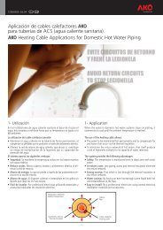
Alarma para cámara frigorífica con salida para 1 foco - AKO
Alarma para cámara frigorífica con salida para 1 foco - AKO
Alarma para cámara frigorífica con salida para 1 foco - AKO

You also want an ePaper? Increase the reach of your titles
YUMPU automatically turns print PDFs into web optimized ePapers that Google loves.
5206H101 Ed.03<br />
<strong>Alarma</strong> <strong>para</strong> <strong>cámara</strong> <strong>frigorífica</strong> <strong>con</strong> <strong>salida</strong> <strong>para</strong> 1 <strong>foco</strong><br />
<strong>Alarma</strong> óptica, acústica y alumbrado de socorro <strong>para</strong> <strong>cámara</strong>s <strong>frigorífica</strong>s a baja<br />
temperatura o <strong>con</strong> atmósfera <strong>con</strong>trolada. Compuestas de una fuente de alimentación<br />
<strong>para</strong> ir montada en el exterior de la <strong>cámara</strong> y un <strong>foco</strong> <strong>con</strong> un pulsador <strong>para</strong> la petición de<br />
socorro desde el interior.<br />
El sistema incorpora 2 funciones de alarma, una que actúa <strong>con</strong> alimentación de red y otra<br />
<strong>con</strong> sus acumuladores <strong>para</strong> garantizar el funcionamineto en caso de corte en el<br />
suministro eléctrico.<br />
1- Datos técnicos<br />
Alimentación: <strong>AKO</strong>-52061 . . . . . . . . . . . . . . . . . . . . . . . . 230 V ~ ± 10%, 50/60 Hz<br />
<strong>AKO</strong>-52066 . . . . . . . . . . . . . . . . . . . . 120 V ~ + 8% - 12%, 50/60 Hz<br />
Potencia máxima absorbida: . . . . . . . . . . . . . . . . . . . . . . . . . . . . . . . . . . . . . . . 10 VA<br />
Autonomía alumbrado + alarma: . . . . . . . . . . . . . . . . . . . . . . . . . . . . . . . . . . > 1 Hora<br />
Acumuladores: . . . . . . . . . . . . . . . . . . . . . . . . . . . . . . . . . . . . . . . . . Ni-MH 700 mAh<br />
Relé auxiliar: . . . . . . . . . . . . . . . . . . . . . . . . . . . . . . . . . . . . . . . . . . . . . 8 A, cos j =1<br />
Temperatura ambiente de trabajo de la fuente de alimentación: . . . . . . . . . . 0 ºC a 50 ºC<br />
Temperatura ambiente de trabajo del <strong>foco</strong>: . . . . . . . . . . . . . . . . . . . . . . . -50 ºC a 50 ºC<br />
Temperatura ambiente de almacenaje de la fuente: . . . . . . . . . . . . . . . . . -30 ºC a 70 ºC<br />
Temperatura ambiente de almacenaje del <strong>foco</strong>: . . . . . . . . . . . . . . . . . . . . -50 ºC a 70 ºC<br />
Grado de protección: . . . . . . . . . . . . . . . . . . . . . . . . . . . . . . . . . . . . . . . . . . . . . IP 65<br />
Categoría de instalación: . . . . . . . . . . . . . . . . . . . . . . . . . . . . . . . . . . II s/ EN 61010-1<br />
Grado de polución:. . . . . . . . . . . . . . . . . . . . . . . . . . . . . . . . . . . . . . . II s/ EN 61010-1<br />
Aislamiento doble entre alimentación, circuito secundario y <strong>salida</strong> relé.<br />
<strong>Alarma</strong> <strong>para</strong> <strong>cámara</strong> <strong>frigorífica</strong> <strong>con</strong> <strong>salida</strong> de 1 <strong>foco</strong>:. . . . . . . . . . . <strong>AKO</strong>-52061 / 52066<br />
Fuente de alimentación de repuesto: . . . . . . . . . . . . . . . . . . . <strong>AKO</strong>-520611 / 520661<br />
Foco de repuesto <strong>con</strong> 2 m de cable: . . . . . . . . . . . . . . . . . . . . . . . . . . . . . <strong>AKO</strong>-52062<br />
2- Instalación<br />
La alarma debe ser instalada en un sitio protegido de las vibraciones, del agua y de los gases<br />
corrosivos, donde la temperatura ambiente no supere el valor reflejado en los datos técnicos.<br />
Para que las alarmas tengan un grado de protección IP65, deberá instalarse correctamente<br />
la junta entre el a<strong>para</strong>to y el perímetro del hueco del panel donde deba montarse.<br />
2.1 Montaje Mural<br />
-Retirar la tapa T del equipo (Fig.1)<br />
-Abrir el equipo y se<strong>para</strong>r el frontal de la caja (Fig.2)<br />
-Realizar los taladros <strong>para</strong> los prensaestopas necesarios <strong>para</strong> entrada de los cables<br />
guiándose por los centros pretroquelados en los laterales de la caja.<br />
-Realizar los 3 taladros <strong>para</strong> fijación de la caja en los centros indicados 1,2,3. (Fig.3)<br />
-Realizar los 3 taladros en la pared siguiendo los agujeros de fijación realizados<br />
previamente en el equipo.<br />
-Fijar los prensaestopas en el equipo.<br />
-Insertar y apretar los 3 tornillos+taco a través de la caja, en los 3 taladros de la pared.<br />
-Insertar los cables en los prensaestopas.<br />
-Montar el frontal en la caja (Fig.2).<br />
-Insertar y apretar los tornillos D,F (Fig.1)<br />
-Después de <strong>con</strong>ectar los cables según el esquema de <strong>con</strong>exionado, cerrar la tapa T,<br />
insertar y apretar los tornillos A,C (Fig.1)<br />
2.2 Montaje Panel (máximo grosor del panel: 3mm)<br />
-Retirar la tapa T del equipo (Fig.1)<br />
-Abrir el equipo y se<strong>para</strong>r el frontal de la caja (Fig.2)<br />
-Reemplazar la junta instalada en el frontal por la junta <strong>para</strong> panelar teniendo en cuenta<br />
su posición adecuada.<br />
-Realizar un hueco en el panel de las dimensiones descritas (214 x 214 mm). (Fig.4)<br />
FIG. 1<br />
<strong>AKO</strong>-52061<br />
<strong>AKO</strong>-52066<br />
E GB<br />
FIG. 2<br />
222,1 mm<br />
140 mm<br />
FIG. 3<br />
<strong>AKO</strong>-520611<br />
<strong>AKO</strong>-520661<br />
140 mm<br />
222,1 mm<br />
<strong>AKO</strong>-52062<br />
214 mm<br />
HUECO<br />
PANEL<br />
FIG. 4<br />
214 mm<br />
-Realizar los taladros <strong>para</strong> los prensaestopas necesarios <strong>para</strong> entrada de los cables<br />
guiándose por los centros pretroquelados en los laterales de la caja.<br />
-Acabar de taladrar los agujeros G, J <strong>con</strong> una broca de 4 mm.(Fig.3)<br />
-Fijar los prensaestopas en el equipo.<br />
-Insertar los cables en los prensaestopas.<br />
-Juntar el frontal <strong>con</strong> la caja, a través del panel, y apretar los tornillos de 45 mm a través<br />
de los taladros D,F,G, J (Fig.3)<br />
-Después de <strong>con</strong>ectar los cables según el esquema de <strong>con</strong>exionado, cerrar la tapa T,<br />
insertar y apretar los tornillos A, C (Fig.1)<br />
2.3 Montaje del Foco<br />
El <strong>foco</strong> debe instalarse en el interior de la <strong>cámara</strong>, junto a la puerta de <strong>salida</strong> <strong>para</strong> que<br />
éste sea siempre visible y a una altura accesible <strong>para</strong> las personas. Se <strong>con</strong>ecta de acuerdo<br />
<strong>con</strong> el esquema de <strong>con</strong>exionado y respetando la situación de los colores de los cables.<br />
Presionar ligeramente<br />
<strong>para</strong> abrir la tapa<br />
2.4 Conexionado:<br />
CONECTAR LAS BATERIAS ANTES DE LA PUESTA EN MARCHA DEL EQUIPO.<br />
Des<strong>con</strong>ectar siempre la alimentación <strong>para</strong> realizar el <strong>con</strong>exionado.<br />
El circuito de alimentación debe estar provisto de un<br />
interruptor <strong>para</strong> su des<strong>con</strong>exión de mínimo 2 A situado<br />
cerca del a<strong>para</strong>to. El cable de alimentación será del tipo<br />
2 2<br />
H05VV-F 2x0.5 mm o H05V-K 2x0.5 mm .<br />
Los cables <strong>para</strong> el <strong>con</strong>exionado del <strong>con</strong>tacto del relé,<br />
2<br />
deberán tener una sección de 2.5 mm .<br />
3- Funciones del frontal<br />
4- Funcionamiento<br />
Una vez <strong>con</strong>ectada la alarma, estará permanentemente luciendo el <strong>foco</strong>. Caso de<br />
producirse un corte en el suministro eléctrico, <strong>con</strong>tinuará luciendo el <strong>foco</strong>. Cuando una<br />
persona en el interior de la <strong>cámara</strong> <strong>frigorífica</strong> desea dar la alarma, presiona el pulsador<br />
del <strong>foco</strong> y se pone en funcionamiento la alarma acústica y luminosa del exterior. Ésta no<br />
<strong>para</strong>rá hasta que se restablezca la posición inicial del pulsador. El sistema funciona tanto<br />
si hay tensión en la red como si no la hay, debido a sus acumuladores. El <strong>con</strong>tacto del relé<br />
auxiliar permite activar alarmas a distancia.<br />
5- Mantenimiento<br />
Limpie la superficie de la alarma <strong>con</strong> un paño suave, agua y jabón. No utilice detergentes<br />
abrasivos, gasolina, alcohol o disolventes.<br />
Este equipo incorpora acumuladores que deben reponerse cuando la autonomía del<br />
equipo es inferior a la duración asignada en las especificaciones del mismo. Al final de la<br />
vida del equipo, se deben llevar los acumuladores a un centro de recogida selectiva ó<br />
bien devolver el equipo al fabricante.<br />
6- Advertencias<br />
Detalle taladros fijación<br />
Taladros de fijación adecuados<br />
<strong>para</strong> caja de empotrar universal<br />
ALARMA VISUAL<br />
ESTADO BATERÍA<br />
ALARMA ACÚSTICA<br />
FOCO CON<br />
PULSADOR<br />
94<br />
60<br />
ALARMA<br />
PERSONA<br />
ENCERRADA<br />
125,5<br />
171<br />
Utilizar la alarma no respetando las instrucciones del fabricante, puede alterar los<br />
requisitos de seguridad del a<strong>para</strong>to.<br />
35<br />
Max. Ø 3,7<br />
8 A<br />
C NO NC<br />
ALARM<br />
41,5<br />
1 2 3 4 5 6 7 8<br />
Alimentación<br />
de red<br />
+12 V 20 mA=<br />
Marrón<br />
Negro<br />
GND<br />
Azul<br />
ENTRADA FOCO<br />
LED Estado batería:<br />
Rojo: Alimentación presente<br />
y batería cargando.<br />
Apagado: <strong>Alarma</strong> funcionando<br />
<strong>con</strong> batería.<br />
LEDs alarma activos:<br />
<strong>Alarma</strong> visual y sonora<br />
activa.
Cold room store alarm with output for 1 lamp<br />
Optical, acoustic alarm with lamp for cold room stores operating at low temperatures or<br />
with <strong>con</strong>trolled atmospheres. Comprised of a power source for mounting on the outside<br />
of the cold room store and a lamp with a pushbutton for requesting help from inside.<br />
The system has 2 alarm functions, one for operation with electrical power supply and<br />
other one to operatre with its batteries in case of electrical power cuts.<br />
1- Technical data<br />
Power supply: <strong>AKO</strong>-52061 . . . . . . . . . . . . . . . . . . . . . . . . 230 V ~ ± 10%, 50/60 Hz<br />
<strong>AKO</strong>-52066 . . . . . . . . . . . . . . . . . . . . 120 V ~ + 8% - 12%, 50/60 Hz<br />
Maximum input power: . . . . . . . . . . . . . . . . . . . . . . . . . . . . . . . . . . . . . . . . . . . 10 VA<br />
Light + alarm autonomy time: . . . . . . . . . . . . . . . . . . . . . . . . . . . . . . . . . . . . > 1 Hour<br />
Batteries: . . . . . . . . . . . . . . . . . . . . . . . . . . . . . . . . . . . . . . . . . . . . . Ni-MH 700 mAh<br />
Auxiliary relay: . . . . . . . . . . . . . . . . . . . . . . . . . . . . . . . . . . . . . . . . . . . . 8 A, cos j =1<br />
Power source working ambient temperature: . . . . . . . . . . . . . . . . . . . . . . 0 ºC to 50 ºC<br />
Lamp working ambient temperature:. . . . . . . . . . . . . . . . . . . . . . . . . . . -50 ºC to 50 ºC<br />
Power source storage ambient temperature: . . . . . . . . . . . . . . . . . . . . . -30 ºC to 70 ºC<br />
Lamp storage ambient temperature: . . . . . . . . . . . . . . . . . . . . . . . . . . . -50 ºC to 70 ºC<br />
Degree protection: . . . . . . . . . . . . . . . . . . . . . . . . . . . . . . . . . . . . . . . . . . . . . . . IP 65<br />
Installation category: . . . . . . . . . . . . . . . . . . . . . . . . . . . . . . . . . . . . . II s/ EN 61010-1<br />
Pollution degree: . . . . . . . . . . . . . . . . . . . . . . . . . . . . . . . . . . . . . . . . II s/ EN 61010-1<br />
Double insulation between the power supply, the se<strong>con</strong>dary circuit and the relay output.<br />
cold room store alarm with 1 lamp:. . . . . . . . . . . . . . . . . . . . . . . <strong>AKO</strong>-52061 / 52066<br />
Spare power source: . . . . . . . . . . . . . . . . . . . . . . . . . . . . . . . <strong>AKO</strong>-520611 / 520661<br />
Spare spotlight with 2 m of cable: . . . . . . . . . . . . . . . . . . . . . . . . . . . . . . <strong>AKO</strong>-52062<br />
2- Installation<br />
The alarm should be installed in a place protected from vibrations, water and corrosive gases,<br />
and where ambient temperature does not surpass the value specified in the technical data.<br />
In order for the alarms to have IP65 protection, the gasket should be properly installed<br />
between the ap<strong>para</strong>tus and the perimeter of the panel cut-out where it is to be fitted.<br />
2.1 Wall mounting<br />
-Remove cover T from the equipment (Fig.1).<br />
-Open the equipment and se<strong>para</strong>te the front part of the housing (Fig.2).<br />
-Drill the holes for the glands that are necessary for the cables to pass through, guided by<br />
the pre-cut centres on the sides of the housing.<br />
-Drill 3 holes for anchoring the housing at the centres indicated 1, 2, 3 (Fig.3).<br />
-Drill 3 holes in the wall, in accordance with the anchoring holes made previously in the<br />
equipment.<br />
-Anchor the glands to the equipment.<br />
-Insert and tighten the 3 screws+plug through the housing, on the 3 holes drilled in the wall.<br />
-Insert the cables into the glands.<br />
-Mount the front part on the housing (Fig.2).<br />
-Insert and tighten screws D, F (Fig.1)<br />
-After <strong>con</strong>necting the cables based on the <strong>con</strong>nection diagram, close cover T, insert<br />
and tighten screws A, C (Fig.1).<br />
2.2 Panel Mounting (maximum panel thickness: 3mm)<br />
-Remove cover T from the equipment (Fig.1).<br />
-Open the equipment and se<strong>para</strong>te the front part of the housing (Fig.2).<br />
-Replace the joint installed at the front by the panelling joint, ensuring that it is in the<br />
right position.<br />
FIG. 1<br />
<strong>AKO</strong>-52061<br />
<strong>AKO</strong>-52066<br />
FIG. 2<br />
222,1 mm<br />
140 mm<br />
FIG. 3<br />
<strong>AKO</strong>-520611<br />
<strong>AKO</strong>-520661<br />
140 mm<br />
222,1 mm<br />
<strong>AKO</strong>-52062<br />
214 mm<br />
PANEL<br />
CUT-OUT<br />
FIG. 4<br />
Av. Roquetes, 30-38 | 08812 Sant Pere de Ribes | Barcelona | España<br />
Tel. (34) 938 142 700 | Fax (34) 938 934 054 | e-mail: ako@ako.com | www.ako.com<br />
214 mm<br />
-Make an opening in the panel with the dimensions indicated (214 x 214 mm) (Fig.4).<br />
-Drill the holes for the glands that are necessary for the cables to pass through, guided<br />
by the pre-cut centres on the sides of the housing.<br />
-Finish drilling holes G, J with a 4 mm bit(Fig.3).<br />
-Anchor the glands to the equipment.<br />
-Insert the cables into the glands.<br />
-Join the front with the housing, through the panel and tighten the 45 mm screws<br />
through holes D, F, G, J (Fig.3).<br />
-After <strong>con</strong>necting the cables in accordance with the <strong>con</strong>nection diagram, close cover T,<br />
and insert and tighten screws A, C (Fig.1).<br />
2.3 Lamp Mounting<br />
The lamp must be installed inside the cold room store, next to the door so that it is always<br />
visible and can easily be reached by any person. Connect the equipment in accordance<br />
with the <strong>con</strong>nection diagram, respecting the position of the cable colours.<br />
2.4 Wiring:<br />
CONNECT THE BATTERIES PRIOR TO STARTING UP THE EQUIPMENT.<br />
Always dis<strong>con</strong>nect the power supply when making the <strong>con</strong>nections.<br />
The power supply circuit should be <strong>con</strong>nected with a<br />
minimum 2 A, switch located close to the unit. Power<br />
2<br />
supply cables should be H05VV-F 2x0,5 mm or<br />
2<br />
H05V-K 2x0,5 mm .<br />
Section of <strong>con</strong>necting wires for relays <strong>con</strong>tacts should<br />
2<br />
be 2,5 mm .<br />
3- Front panel functions<br />
4- Operation<br />
After <strong>con</strong>necting the alarm, the lamp will be lit permanently. If there is a power failure,<br />
the lamp will <strong>con</strong>tinue to be lit. In the event that anyone inside the cold room store<br />
wishes to raise the alarm, press the lamp pushbutton and the acoustic and visual alarm<br />
on the outside of the cold room store will be set in operation. It will not stop until the<br />
pushbutton is returned to its initial position. The system will operate with and without<br />
electricity, due to the energy accumulated by the battery. Contact of the auxiliary relay<br />
enables the alarms to be activated from a distance.<br />
5- Maintenance<br />
Clean the alarm surface with a soft cloth, soap and water. Do not use abrasive<br />
detergents, petrol, alcohol or solvents.<br />
This unit includes batteries which must be replaced when the device's autonomy time is<br />
below the indicated in the specifications. At the end of the unit's service life. the batteries<br />
should be disposed of at a selective refuse collection site or return to the manufacturer.<br />
6- Warnings<br />
Press lightly to open the cover.<br />
View of holes drilled<br />
for anchoring.<br />
Anchoring holes that are suitable for use<br />
in housings with universal embedding.<br />
VISUAL ALARM<br />
BATTERY STATUS<br />
ACOUSTIC ALARM<br />
LAMP WITH<br />
PUSHBUTTON<br />
94<br />
60<br />
PERSON<br />
TRAPPED<br />
ALARM<br />
125,5<br />
171<br />
The use of the unit without observing the manufacturer's instructions may alter its safety<br />
qualification.<br />
<strong>AKO</strong> ELECTROMECÀNICA, S.A.L.<br />
Nos reservamos el derecho de suministrar materiales que pudieran diferir levemente de los<br />
descritos en nuestras Hojas Técnicas.Información actualizada en nuestra web: www.ako.com .<br />
We reserve the right to supply materials that might vary slightly to those described in our Technical<br />
Sheets. Updated information is available on our website: www.ako.com<br />
35<br />
Max. Ø 3,7<br />
8 A<br />
C NO NC<br />
ALARM<br />
41,5<br />
1 2 3 4 5 6 7 8<br />
Power<br />
supply<br />
+12 V 20 mA=<br />
Brown<br />
Black<br />
GND<br />
Blue<br />
LAMP INPUT<br />
Battery status LED:<br />
Red: power supply.<br />
OFF: Alarm working with<br />
batteries.<br />
Alarm LEDs <strong>con</strong>nected:<br />
Visual and acoustic alarm<br />
ON.<br />
355206101 REV.02 2012