(agua caliente sanitaria). - AKO
(agua caliente sanitaria). - AKO
(agua caliente sanitaria). - AKO

Create successful ePaper yourself
Turn your PDF publications into a flip-book with our unique Google optimized e-Paper software.
6- Instrucciones de aplicación<br />
y comprobaciones<br />
La instalación, comprobaciones, y conexión al suministro eléctrico<br />
deben ser realizadas por personal cualificado.<br />
6.1. Instrucciones de aplicación<br />
• La instalación de la tubería ha de estar terminada, con la pintura<br />
seca y el ensayo de presión superado.<br />
• La superficie en que se ha de aplicar el cable calefactor ha de estar<br />
exenta de aristas cortantes.<br />
• Las tuberías han de estar separadas de las paredes o techos un<br />
mínimo de 50 mm para facilitar la instalación del aislamiento térmico.<br />
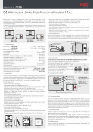
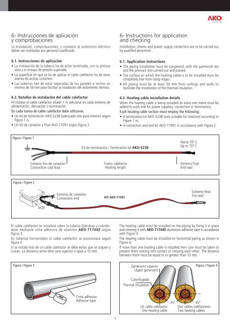
6.2. Detalles de instalación del cable calefactor<br />
Al instalar el cable calefactor añadir 1 m adicional en cada extremo de<br />
alimentación, derivación o terminación.<br />
En cada tramo de cable calefactor debe utilizarse:<br />
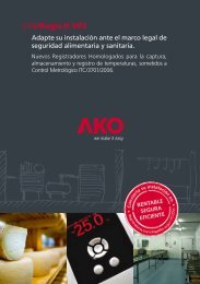
• Un kit de terminación <strong>AKO</strong>-5238 (adecuado sólo para interior) según<br />
figura 1 o,<br />
• Un kit de conexión y final <strong>AKO</strong>-71091 según figura 2.<br />
Figura / Figure 1<br />
Figura / Figure 2<br />
Extremo frío de conexión<br />
Connection cold lead<br />
M20<br />
Extremo de conexión<br />
Connection end<br />
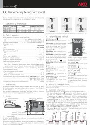
El cable calefactor se instalará sobre la tubería fijándose y cubriéndose<br />
mediante cinta adhesiva de aluminio <strong>AKO</strong>-717440 según<br />
figura 3.<br />
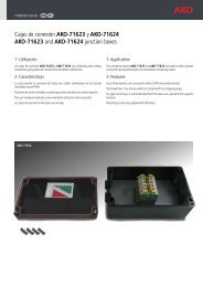
En tuberías horizontales el cable calefactor se posicionará según<br />
figura 4.<br />
Si se instala más de un cable calefactor se debe evitar que se toquen o<br />
crucen. La distancia entre ellos será superior o igual a 10 mm.<br />
Kit de terminación / Termination kit <strong>AKO</strong>-5238<br />
Tramo calefactor<br />
Heating lenght<br />
KIT <strong>AKO</strong>-71091<br />
5<br />
6- Instructions for application<br />
and checking<br />
Installation, checks and power supply connection are to be carried out<br />
by qualified personnel.<br />
6.1. Application instructions<br />
• The piping installation must be completed, with the paintwork dry<br />
and the pressure test carried out and passed.<br />
• The surface on which the heating cable is to be installed must be<br />
completely free from sharp edges.<br />
• All piping must be at least 50 mm from ceilings and walls to<br />
facilitate the installation of the thermal insulation.<br />
6.2. Heating cable installation details<br />
When the heating cable is being installed an extra one metre must be<br />
added to each end for power supplies, connection or termination.<br />
Each heating cable section must employ the following:<br />
• A termination kit <strong>AKO</strong>-5238 (only suitable for interiors) according to<br />
Figure 1 or,<br />
• A connection and end kit <strong>AKO</strong>-71091 in accordance with Figure 2.<br />
Hasta 70º C<br />
Up to 70º C<br />
Extremo final<br />
End-seal<br />
Extremo final<br />
Ens-seal<br />
The heating cable must be installed on the piping by fixing it in place<br />
and covering it with <strong>AKO</strong>-717440 aluminium adhesive tape in accordance<br />
with Figure 3.<br />
The heating cable must be installed on horizontal piping as shown in<br />
Figure 4.<br />
If more than one heating cable is installed then care must be taken to<br />
prevent them coming into contact or crossing each other. The distance<br />
between them must be equal to or greater than 10 mm.<br />
Figura / Figure 3 Generatriz superior<br />
Upper generatrix<br />
Figura / Figure 4<br />
Cinta adhesiva<br />
Adhesive tape<br />
Calorifugado<br />
Thermal insulation<br />
Un cable calefactor<br />
One heating cable<br />
45º 45º<br />
Dos cables calefactores<br />
Two heating cables