(agua caliente sanitaria). - AKO
(agua caliente sanitaria). - AKO
(agua caliente sanitaria). - AKO

Create successful ePaper yourself
Turn your PDF publications into a flip-book with our unique Google optimized e-Paper software.
4.5- Ejemplo<br />
Datos<br />
1) Temperatura de la tubería a mantener: 50 °C<br />
2) Temperatura mínima ambiente: 10 °C<br />
3) Tipo de aislamiento térmico y espesor: Espuma elastomérica con<br />
λ=0,038 W/mK y espesor de 20 mm<br />
4) Material, diámetro y longitud de la tubería: Cobre, diámetro de<br />
25 mm, y una longitud de 60 m<br />
5) Tensión de alimentación: 230 V<br />
Cálculo de las pérdidas térmicas<br />
q =<br />
2 • π • 0,038 • ( 50 - 10 ) • 1,3<br />
In<br />
( 25 + 2 • 20 )<br />
25<br />
Selección del cable calefactor: <strong>AKO</strong>-71015 s/ tabla1 (15 W/m a<br />
230 V)<br />
Forma de instalación: Lineal<br />
Consumo: 0,0652 A/m (s/tabla 2) x 60= 3,91 A<br />
Calibre del interruptor magnetotérmico: 5 A<br />
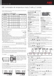
5- Control de temperatura<br />
= 13 W/m q =<br />
El termostato electrónico conecta el cable calefactor cuando la temperatura<br />
de la tubería es inferior al valor de la temperatura de ajuste (Set<br />
point) y, desconecta el cable calefactor cuando la tubería alcanza una<br />
temperatura correspondiente a la suma de la temperatura de ajuste y<br />
el diferencial.<br />
El sistema de control consta de 2 partes:<br />
<strong>AKO</strong>-14726:<br />
Termostato electrónico panelable, tipo multisonda con 2 relés, para instalación<br />
en panel mediante un hueco de 70,5 x 28,5 mm.<br />
El primer relé se utiliza para el control de la temperatura de la tubería.<br />
El segundo relé puede utilizarse como alarma de mínima y/o máxima<br />
temperatura<br />
<strong>AKO</strong>-15595:<br />
Sonda de temperatura Pt 100 (3 hilos) de –40 a +200 °C a instalar en<br />
la superficie de la tubería sin que toque el cable calefactor.<br />
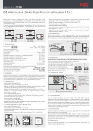
5.1. Detalles de instalación<br />
La sonda de temperatura determina los ciclos de funcionamiento del<br />
circuito eléctrico, por lo que debe instalarse en el punto de la tubería<br />
donde:<br />
• El <strong>agua</strong> permanezca mayor tiempo de forma estática en relación<br />
con el resto de tuberías controladas por el mismo termostato<br />
• No reciba la influencia de puentes térmicos, como soportes, válvulas,<br />
bombas, etc.<br />
La posición de la sonda de temperatura respecto al cable calefactor<br />
debe ser como mínimo de 50 mm<br />
La prolongación de la sonda hasta el panel de control debe realizarse<br />
mediante cable apantallado de 3 hilos.<br />
El termostato ha de actuar sobre un contactor para la conexión y desconexión<br />
del o los circuitos eléctricos.<br />
El número de termostatos o controles a instalar en el sistema depende<br />
de las características particulares de cada instalación.<br />
4<br />
4.5- Example<br />
Data<br />
1) Piping temperature to be maintained: 50 °C<br />
2) Minimum ambient temperature: 10 °C<br />
3) Type of thermal insulation and thickness: Elastomer foam with λ=<br />
0.038 W/mK and thickness of 20 mm<br />
4) Piping material, diameter and length: Copper, 25 mm diameter and<br />
length of 60 metres<br />
5) Power supply voltage: 230 V<br />
Heat losses calculation<br />
2 • π • 0,038 • ( 50 - 10 ) • 1,3<br />
In<br />
( 25 + 2 • 20 )<br />
25<br />
= 13 W/m<br />
Heating cable selection: <strong>AKO</strong>-71015 according to Table 1 (15 W/m<br />
at 230 V)<br />
Form of installation: Linear<br />
Consumption: 0.0652 A/m (according to Table 2) x 60 = 3.91 A<br />
Breaker circuit size: 5 A<br />
5- Temperature control<br />
The electronic thermostat will switch the heating cable on when the<br />
temperature inside the piping is less than the set-point and will switch<br />
the heating cable off when the temperature reaches the sum of the<br />
set-point and differential temperatures.<br />
The control system comprises two sections:<br />
<strong>AKO</strong>-14726:<br />
Panel-mounted electronic thermostat, multi-sensor type, with two<br />
relays, for panel installation in a 70.5 x 28.5 mm cut-out.<br />
The first relay is employed to control the piping temperature.<br />
The second relay can be used for minimum and/or maximum<br />
temperature alarm.<br />
<strong>AKO</strong>-15595:<br />
Pt 100 temperature sensor (3 wire) from -40ºC to +200°C for surface<br />
mounting on the piping without it actually coming into contact with<br />
the heating cable.<br />
5.1. Installation details<br />
The temperature sensor determines the operating cycles for the electric<br />
circuit and must therefore be installed at the point in the piping where:<br />
• The water remains the longest length of time in a static manner<br />
with respect to the rest of the piping controlled by the same thermostat<br />
• It is not influenced by thermal bridges, such as supports, valves and<br />
pumps etc.<br />
The temperature sensor position with respect to the heating cable must<br />
be a minimum of 50 mm.<br />
The connection between the sensor and the control panel must be<br />
made with 3 wire brained cable.<br />
The thermostat must operate a contactor for the switching on and off<br />
of the electric circuits.<br />
The number of thermostats or controls to be installed in the system will<br />
depend on the specific characteristics of each installation.