(agua caliente sanitaria). - AKO
(agua caliente sanitaria). - AKO
(agua caliente sanitaria). - AKO

You also want an ePaper? Increase the reach of your titles
YUMPU automatically turns print PDFs into web optimized ePapers that Google loves.
1200H300 Ed.04 E<br />
1- Utilización<br />
GB<br />
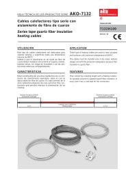
Aplicación de cables calefactores <strong>AKO</strong><br />
para tuberías de ACS (<strong>agua</strong> <strong>caliente</strong> <strong>sanitaria</strong>).<br />
<strong>AKO</strong> Heating Cable Applications for Domestic Hot Water Piping<br />
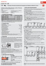
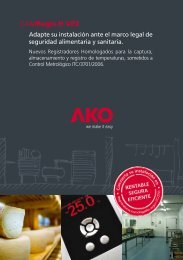
En las instalaciones de <strong>agua</strong> <strong>caliente</strong> <strong>sanitaria</strong> al dejar de circular el<br />
<strong>agua</strong>, ésta empieza a enfriarse hasta que su temperatura se iguala a la<br />
del ambiente.<br />
La utilización del cable calefactor permite:<br />
• Mantener el <strong>agua</strong> <strong>caliente</strong> en la tubería de forma permanente, al<br />
compensar las pérdidas que se producen a través del aislamiento térmico.<br />
• Eliminar la red de retorno de <strong>agua</strong> <strong>caliente</strong>, que de por sí, constituye<br />
un riesgo de multiplicación de la legionela por su capacidad de<br />
retención del <strong>agua</strong>.<br />
El sistema aporta las siguientes ventajas:<br />
• Seguridad: Se mantiene la temperatura incluso en los brazos muertos<br />
con <strong>agua</strong> estática.<br />
• Reduce costes: Menos tubería, bomba y aislamiento térmico al eliminar<br />
la red de retorno.<br />
• Ahorro de energía: La que se pierde a través de los aislamientos térmicos<br />
en la red de retorno.<br />
• Ahorro de <strong>agua</strong>: Al disponer <strong>caliente</strong> e instantáneo en los grifos un<br />
líquido que cada vez es más escaso.<br />
• Fácil de instalar: Por profesional electricista utilizando materiales y<br />
accesorios habituales de instalación eléctrica.<br />
1- Application<br />
Temperatura ambiente<br />
Ambient temperature Tubería<br />
Pipe<br />
Aislamiento térmico<br />
Thermal insulation<br />
1<br />
When the water in domestic hot water systems stops circulating, it<br />
commences to cool until the ambient temperature is reached.<br />
The use of the heating cable allows:<br />
• The water to be maintained hot permanently and to compensate for<br />
any losses that occur via the thermal insulation.<br />
• To eliminate the return network of hot water, that itself produce<br />
a risk of legionella multiply for its capacity of water retention.<br />
The system provides the following advantages:<br />
• Safety: The temperature is maintained even in dead arms with static<br />
water.<br />
• It reduces costs: Less piping, pump and thermal insulation eliminate<br />
the return network.<br />
• Energy savings: That which is lost through the thermal insulation in<br />
the return network.<br />
• Water savings: By having an ever-increasingly scarce liquid both hot<br />
and instantaneous at the taps.<br />
• Easy to install: By a professional electrician using normal electrical<br />
installation materials and accessories.<br />
Cable calefactor<br />
Heating cable
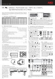
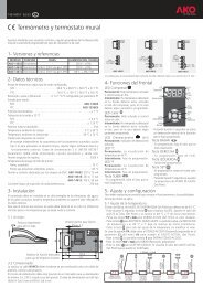
Las estadísticas internacionales indican<br />
que el riesgo más elevado de aparición<br />
de legionela es en los sistemas de <strong>agua</strong><br />
<strong>caliente</strong> centralizados.<br />
International statistics show that the risk<br />
of legionella is higher in centralised hot<br />
water systems.<br />
70 ºC<br />
60 ºC<br />
50 ºC<br />
45 ºC<br />
37 ºC<br />
20 ºC<br />
100% muerte rápida<br />
100% die fastly<br />
2- Características del cable<br />
El cable calefactor que se aplica es de tipo paralelo y de potencia de<br />
entrega por metro lineal constante. Se caracteriza porque el conductor<br />
de calentamiento está enrollado en espiral alrededor de los dos<br />
conductores aislados del cable, con los que hace contacto alternativamente<br />
en unos puntos determinados. El cable va formando internamente,<br />
un sistema de muchas resistencias en paralelo alimentadas<br />
por los dos conductores a través de los puntos de contacto.<br />
La potencia de entrega por metro lineal de cable es constante e<br />
independiente de la longitud del mismo, o sea, a más longitud de<br />
cable, más potencia total, pero la potencia por metro lineal continua<br />
siendo la misma. Esta constitución, permite que pueda ser cortado y<br />
terminado a medida en obra y conectarse directamente a 230 V, lo<br />
cual facilita el proceso de instalación.<br />
Especificaciones técnicas de los cables: Consultar hoja técnica 7110H010<br />
3- Accesorios<br />
90% muere en 2 min<br />
90% dies within 2 min<br />
90% muere en 2 h<br />
90% dies within 2 h<br />
no se multiplica / It does not multiply<br />
desarrollo óptimo<br />
Optimum growth<br />
bacteria en letargo que se<br />
multiplicará con temperaturas<br />
favorables<br />
Dormant bacteria to multiply<br />
under favourable temperatures<br />
Efecto de las temperaturas<br />
en la bacteria de la legionela<br />
Temperature effect<br />
on legionella bacteria<br />
<strong>AKO</strong>-71091: Kit de conexión y final para proteger y aislar los<br />
extremos del cable calefactor<br />
<strong>AKO</strong>-5238: Kit terminación para proteger y aislar los extremos del<br />
cable calefactor (adecuado sólo para interior).<br />
<strong>AKO</strong>-712699: Tubo de silicona para sellado<br />
<strong>AKO</strong>-717445: Juego 5 etiquetas de señalización <strong>AKO</strong>-TRACE<br />
<strong>AKO</strong>-717440: Rollo 50 m de cinta adhesiva de aluminio<br />
Material opcional recomendable:<br />
<strong>AKO</strong>-14726: Termostato electrónico panelable<br />
<strong>AKO</strong>-15595: Sonda de temperatura Pt 100<br />
<strong>AKO</strong>-71751: Juego 5 etiquetas para la señalización de tramos calefactores<br />
Caja de conexión: Con entradas M20. En instalaciones a la intemperie<br />
es necesario un IP≥65<br />
Sistema tradicional / Traditional system<br />
Retorno / Return<br />
Depósito <strong>agua</strong><br />
<strong>caliente</strong> 60 ºC<br />
Hot water<br />
tank 60 ºC<br />
Nuevo concepto / New concept<br />
Depósito <strong>agua</strong><br />
<strong>caliente</strong> 60 ºC<br />
Hot water<br />
tank 60 ºC<br />
Sistema indicado en el Informe Técnico UNE 100030 IN.<br />
Consúltenos: Somos especilistas y le optimizaremos el diseño.<br />
System indicated in the UNE 100030 IN Technical Report.<br />
Contact us: We are specialist and we will optimise the design.<br />
2<br />
Impulsión / Impulsion<br />
2- Cable features<br />
The heating cable that is applied is the parallel type and constant<br />
wattage per linear metre. It is characterised because the heating<br />
conductor is wound in a spiral around the two insulated conductors,<br />
with which it makes contact alternatively at specific points. Internally,<br />
the cable forms a system of many parallel resistances that are fed by<br />
the two conductors at the contact points.<br />
The wattage per linear metre of cable is constant and independent of<br />
its length. This means that the longer the cable, the greater the total<br />
power, but the power per metre length remains the same. This form of<br />
construction means that it can be cut-to-length and terminated onsite<br />
and directly connected to 230 V, which facilitates the installation<br />
process.<br />
Technical cable specifications: See Data Sheet 7110H010<br />
3- Accessories<br />
<strong>AKO</strong>-71091: Connection and end kit for protecting and seal the ends<br />
of the heating cable<br />
<strong>AKO</strong>-5238: Termination kit for protecting and seal the ends of the<br />
heating cable (suitable only for indoor use).<br />
<strong>AKO</strong>-712699: Silicone sealing tube<br />
<strong>AKO</strong>-717445: Set of five <strong>AKO</strong>-TRACE indicator labels<br />
<strong>AKO</strong>-717440: 50 metre roll of adhesive aluminium tape<br />
Recommended optional material:<br />
<strong>AKO</strong>-14726: Panel-mounted electronic thermostat<br />
<strong>AKO</strong>-15595: Pt 100 temperature sensor<br />
<strong>AKO</strong>-71751: Set of five labels for identifying heating lengths<br />
Junction box: With M20 entries. Outside installations require<br />
an IP≥65
4- Potencias requeridas, selección del cable<br />
calefactor y consumo<br />
4.1- Cálculo de perdidas térmicas en tuberías<br />
donde<br />
q es el flujo de calor (pérdidas térmicas), en W/m<br />
λ es la conductividad térmica del aislamiento térmico en<br />
W/(m·K)<br />
Ta fluido es la temperatura que se desea mantener la tubería en °C<br />
Ta q =<br />
ambiente es la temperatura mínima ambiente en el emplazamiento de<br />
las tuberías en °C<br />
Fs es el factor de seguridad para compensar las tolerancias; del<br />
cable calefactor, del aislamiento térmico, y de la tensión de alimentación.<br />
Se recomienda un valor entre 1,25 y 1,3<br />
D es el diámetro exterior de la tubería en mm<br />
e es el espesor del aislamiento térmico en mm<br />
2 • π • λ • ( Ta fluido -Ta ambiente ) • Fs<br />
( D + 2 • e )<br />
In<br />
D<br />
4.2- Selección del cable calefactor<br />
Tabla 1:<br />
3<br />
4- Powers required, heating cable selection<br />
and consumption<br />
4.1- Calculation of heat losses in piping<br />
Referencias / References <strong>AKO</strong>-71010 <strong>AKO</strong>-71015 <strong>AKO</strong>-71020 <strong>AKO</strong>-71025 <strong>AKO</strong>-71030 <strong>AKO</strong>-71035<br />
Potencias (W/m) a 230V<br />
Powers (W/m) at 230V<br />
En tuberías de materiales plásticos, la potencia del cable calefactor a utilizar<br />
ha de ser inferior o igual a 15 W/m, para asegurar que la temperatura<br />
del cable calefactor no excede la temperatura límite de los materiales.<br />
Especificaciones técnicas de los cables: Consultar hoja técnica 7110H010<br />
4.3. Forma de instalación<br />
• Lineal: Para facilitar el montaje, es aconsejable que el diseño sea<br />
realizado con un ratio 1 (1 m de cable calefactor por cada metro de<br />
tubería).<br />
• En espiral: En caso que sea necesario aplicar un ratio entre<br />
1 y 1.5<br />
4.4. Consumo y protección eléctrica<br />
Tabla 2:<br />
where<br />
q is the heat flow (heat losses), in W/m<br />
λ is the thermal conductivity of the thermal insulation in<br />
W/(m·K)<br />
Ta fluido is the temperature that the piping is to be maintained at in ºC<br />
Ta q =<br />
ambiente is the minimum ambient temperature at the piping<br />
site in ºC<br />
Fs is the safety factor for tolerance compensation of the heating<br />
cable, the thermal insulation and the power supply voltage. A<br />
value of between 1.25 and 1.3 is recommended<br />
D is the outside diameter of the piping in mm<br />
e is the thermal insulation thickness in mm<br />
2 • π • λ • ( Ta fluido -Ta ambiente ) • Fs<br />
( D + 2 • e )<br />
In<br />
D<br />
4.1- Heating cable selection<br />
Table 1:<br />
10 15 20 25 30 35<br />
In plastic piping, the heating cable power must be less than or equal to<br />
15 W/m, in order to guarantee that the heating cable temperature does<br />
not exceed the plastic's limiting temperature.<br />
Technical cable specifications: See Data Sheet 7110H010.<br />
4.3. Form of installation<br />
• Linear: To facilitate the installation, it is recommended that the<br />
design be carried out with a ratio of 1 (1 metre of heating cable to<br />
one metre of piping length).<br />
• In spiral: In case of necessity, a ratio of between 1 and 1.5 may be<br />
used.<br />
4.4. Electrical consumption and protection<br />
Table 2:<br />
Referencias / References <strong>AKO</strong>-71010 <strong>AKO</strong>-71015 <strong>AKO</strong>-71020 <strong>AKO</strong>-71025 <strong>AKO</strong>-71030 <strong>AKO</strong>-71035<br />
Consumos (A/m) a 230V<br />
Consumptions (A/m) at 230V<br />
Longitud máx circuito (m)<br />
Maximum circuit length (m)<br />
Se recomienda distribuir los tramos de cable calefactor de la instalación<br />
en diferentes circuitos eléctricos.<br />
Cada circuito eléctrico debe protegerse mediante un interruptor diferencial<br />
con una sensibilidad de 30 mA, y un interruptor magnetotérmico<br />
adecuado al consumo nominal.<br />
El consumo nominal del circuito eléctrico se obtiene al multiplicar los<br />
metros totales de cada referencia de cable calefactor por su consumo<br />
unitario s/ tabla 2.<br />
0.0435 0.06252 0.087 0.1087 0.1304 0.1522<br />
150 125 95 85 80 65<br />
It is recommended that the various heating cable sections of the<br />
installation be distributed in different electric circuits.<br />
Each electric circuit must be protected using a 30 mA sensitivity residual<br />
current circuit, together with a circuit breaker in accordance with the<br />
rated consumption.<br />
The rated consumption of the electric circuit is obtained by multiplying<br />
the total metres of each heating cable reference by its unit consumption<br />
given in Table 2.
4.5- Ejemplo<br />
Datos<br />
1) Temperatura de la tubería a mantener: 50 °C<br />
2) Temperatura mínima ambiente: 10 °C<br />
3) Tipo de aislamiento térmico y espesor: Espuma elastomérica con<br />
λ=0,038 W/mK y espesor de 20 mm<br />
4) Material, diámetro y longitud de la tubería: Cobre, diámetro de<br />
25 mm, y una longitud de 60 m<br />
5) Tensión de alimentación: 230 V<br />
Cálculo de las pérdidas térmicas<br />
q =<br />
2 • π • 0,038 • ( 50 - 10 ) • 1,3<br />
In<br />
( 25 + 2 • 20 )<br />
25<br />
Selección del cable calefactor: <strong>AKO</strong>-71015 s/ tabla1 (15 W/m a<br />
230 V)<br />
Forma de instalación: Lineal<br />
Consumo: 0,0652 A/m (s/tabla 2) x 60= 3,91 A<br />
Calibre del interruptor magnetotérmico: 5 A<br />
5- Control de temperatura<br />
= 13 W/m q =<br />
El termostato electrónico conecta el cable calefactor cuando la temperatura<br />
de la tubería es inferior al valor de la temperatura de ajuste (Set<br />
point) y, desconecta el cable calefactor cuando la tubería alcanza una<br />
temperatura correspondiente a la suma de la temperatura de ajuste y<br />
el diferencial.<br />
El sistema de control consta de 2 partes:<br />
<strong>AKO</strong>-14726:<br />
Termostato electrónico panelable, tipo multisonda con 2 relés, para instalación<br />
en panel mediante un hueco de 70,5 x 28,5 mm.<br />
El primer relé se utiliza para el control de la temperatura de la tubería.<br />
El segundo relé puede utilizarse como alarma de mínima y/o máxima<br />
temperatura<br />
<strong>AKO</strong>-15595:<br />
Sonda de temperatura Pt 100 (3 hilos) de –40 a +200 °C a instalar en<br />
la superficie de la tubería sin que toque el cable calefactor.<br />
5.1. Detalles de instalación<br />
La sonda de temperatura determina los ciclos de funcionamiento del<br />
circuito eléctrico, por lo que debe instalarse en el punto de la tubería<br />
donde:<br />
• El <strong>agua</strong> permanezca mayor tiempo de forma estática en relación<br />
con el resto de tuberías controladas por el mismo termostato<br />
• No reciba la influencia de puentes térmicos, como soportes, válvulas,<br />
bombas, etc.<br />
La posición de la sonda de temperatura respecto al cable calefactor<br />
debe ser como mínimo de 50 mm<br />
La prolongación de la sonda hasta el panel de control debe realizarse<br />
mediante cable apantallado de 3 hilos.<br />
El termostato ha de actuar sobre un contactor para la conexión y desconexión<br />
del o los circuitos eléctricos.<br />
El número de termostatos o controles a instalar en el sistema depende<br />
de las características particulares de cada instalación.<br />
4<br />
4.5- Example<br />
Data<br />
1) Piping temperature to be maintained: 50 °C<br />
2) Minimum ambient temperature: 10 °C<br />
3) Type of thermal insulation and thickness: Elastomer foam with λ=<br />
0.038 W/mK and thickness of 20 mm<br />
4) Piping material, diameter and length: Copper, 25 mm diameter and<br />
length of 60 metres<br />
5) Power supply voltage: 230 V<br />
Heat losses calculation<br />
2 • π • 0,038 • ( 50 - 10 ) • 1,3<br />
In<br />
( 25 + 2 • 20 )<br />
25<br />
= 13 W/m<br />
Heating cable selection: <strong>AKO</strong>-71015 according to Table 1 (15 W/m<br />
at 230 V)<br />
Form of installation: Linear<br />
Consumption: 0.0652 A/m (according to Table 2) x 60 = 3.91 A<br />
Breaker circuit size: 5 A<br />
5- Temperature control<br />
The electronic thermostat will switch the heating cable on when the<br />
temperature inside the piping is less than the set-point and will switch<br />
the heating cable off when the temperature reaches the sum of the<br />
set-point and differential temperatures.<br />
The control system comprises two sections:<br />
<strong>AKO</strong>-14726:<br />
Panel-mounted electronic thermostat, multi-sensor type, with two<br />
relays, for panel installation in a 70.5 x 28.5 mm cut-out.<br />
The first relay is employed to control the piping temperature.<br />
The second relay can be used for minimum and/or maximum<br />
temperature alarm.<br />
<strong>AKO</strong>-15595:<br />
Pt 100 temperature sensor (3 wire) from -40ºC to +200°C for surface<br />
mounting on the piping without it actually coming into contact with<br />
the heating cable.<br />
5.1. Installation details<br />
The temperature sensor determines the operating cycles for the electric<br />
circuit and must therefore be installed at the point in the piping where:<br />
• The water remains the longest length of time in a static manner<br />
with respect to the rest of the piping controlled by the same thermostat<br />
• It is not influenced by thermal bridges, such as supports, valves and<br />
pumps etc.<br />
The temperature sensor position with respect to the heating cable must<br />
be a minimum of 50 mm.<br />
The connection between the sensor and the control panel must be<br />
made with 3 wire brained cable.<br />
The thermostat must operate a contactor for the switching on and off<br />
of the electric circuits.<br />
The number of thermostats or controls to be installed in the system will<br />
depend on the specific characteristics of each installation.
6- Instrucciones de aplicación<br />
y comprobaciones<br />
La instalación, comprobaciones, y conexión al suministro eléctrico<br />
deben ser realizadas por personal cualificado.<br />
6.1. Instrucciones de aplicación<br />
• La instalación de la tubería ha de estar terminada, con la pintura<br />
seca y el ensayo de presión superado.<br />
• La superficie en que se ha de aplicar el cable calefactor ha de estar<br />
exenta de aristas cortantes.<br />
• Las tuberías han de estar separadas de las paredes o techos un<br />
mínimo de 50 mm para facilitar la instalación del aislamiento térmico.<br />
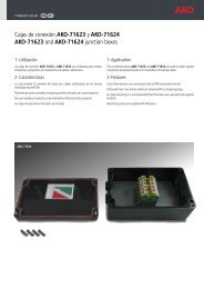
6.2. Detalles de instalación del cable calefactor<br />
Al instalar el cable calefactor añadir 1 m adicional en cada extremo de<br />
alimentación, derivación o terminación.<br />
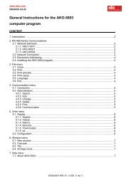
En cada tramo de cable calefactor debe utilizarse:<br />
• Un kit de terminación <strong>AKO</strong>-5238 (adecuado sólo para interior) según<br />
figura 1 o,<br />
• Un kit de conexión y final <strong>AKO</strong>-71091 según figura 2.<br />
Figura / Figure 1<br />
Figura / Figure 2<br />
Extremo frío de conexión<br />
Connection cold lead<br />
M20<br />
Extremo de conexión<br />
Connection end<br />
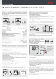
El cable calefactor se instalará sobre la tubería fijándose y cubriéndose<br />
mediante cinta adhesiva de aluminio <strong>AKO</strong>-717440 según<br />
figura 3.<br />
En tuberías horizontales el cable calefactor se posicionará según<br />
figura 4.<br />
Si se instala más de un cable calefactor se debe evitar que se toquen o<br />
crucen. La distancia entre ellos será superior o igual a 10 mm.<br />
Kit de terminación / Termination kit <strong>AKO</strong>-5238<br />
Tramo calefactor<br />
Heating lenght<br />
KIT <strong>AKO</strong>-71091<br />
5<br />
6- Instructions for application<br />
and checking<br />
Installation, checks and power supply connection are to be carried out<br />
by qualified personnel.<br />
6.1. Application instructions<br />
• The piping installation must be completed, with the paintwork dry<br />
and the pressure test carried out and passed.<br />
• The surface on which the heating cable is to be installed must be<br />
completely free from sharp edges.<br />
• All piping must be at least 50 mm from ceilings and walls to<br />
facilitate the installation of the thermal insulation.<br />
6.2. Heating cable installation details<br />
When the heating cable is being installed an extra one metre must be<br />
added to each end for power supplies, connection or termination.<br />
Each heating cable section must employ the following:<br />
• A termination kit <strong>AKO</strong>-5238 (only suitable for interiors) according to<br />
Figure 1 or,<br />
• A connection and end kit <strong>AKO</strong>-71091 in accordance with Figure 2.<br />
Hasta 70º C<br />
Up to 70º C<br />
Extremo final<br />
End-seal<br />
Extremo final<br />
Ens-seal<br />
The heating cable must be installed on the piping by fixing it in place<br />
and covering it with <strong>AKO</strong>-717440 aluminium adhesive tape in accordance<br />
with Figure 3.<br />
The heating cable must be installed on horizontal piping as shown in<br />
Figure 4.<br />
If more than one heating cable is installed then care must be taken to<br />
prevent them coming into contact or crossing each other. The distance<br />
between them must be equal to or greater than 10 mm.<br />
Figura / Figure 3 Generatriz superior<br />
Upper generatrix<br />
Figura / Figure 4<br />
Cinta adhesiva<br />
Adhesive tape<br />
Calorifugado<br />
Thermal insulation<br />
Un cable calefactor<br />
One heating cable<br />
45º 45º<br />
Dos cables calefactores<br />
Two heating cables
El aislamiento térmico debe ser adecuado a la instalación, y en caso de<br />
instalarse a la intemperie debe disponer de una cubierta de protección.<br />
La fijación de la cubierta del aislamiento mediante tornillos debe realizarse<br />
con la precaución de que su longitud no pueda dañar el cable calefactor.<br />
Para mayor información en cuanto a la instalación de los cables calefactores<br />
consultar la hoja técnica 7210H050.<br />
6.3. Comprobaciones<br />
Instalado el cable con el kit correspondiente y conexionado a caja, es<br />
necesario medir y comprobar:<br />
• La resistencia de aislamiento a 500 (con un megóhmetro) ha de<br />
ser superior a 20 M. La medición se realizará entre los cables conductores<br />
y la trenza metálica.<br />
• La resistencia eléctrica entre los dos conductores del cable calefactor.<br />
Los valores obtenidos se registrarán y guardarán junto a la documentación<br />
de la instalación.<br />
Instalado el calorifugado, es necesario volver a realizar los dos ensayos<br />
anteriores, comprobando que los resultados obtenidos sean similares y<br />
además comprobar:<br />
• La instalación de las etiquetas <strong>AKO</strong>-717445 sobre el calorifugado.<br />
Energizar el cable calefactor y comprobar:<br />
• El voltaje en la caja de conexión<br />
• El consumo del tramo calefactor en A<br />
Los valores obtenidos se registrarán y guardarán junto a la documentación<br />
de la instalación.<br />
En el caso de que alguna medición no haya sido correcta, revisar el<br />
cable calefactor antes de continuar con la instalación.<br />
7- Mantenimiento<br />
Se recomienda una inspección del sistema con una frecuencia anual.<br />
El chequeo consiste en:<br />
• Inspeccionar las cajas de conexión para descartar la presencia de<br />
<strong>agua</strong> o humedad en su interior. Si se detecta esta presencia, las<br />
cajas deben secarse e identificar la causa del ingreso de <strong>agua</strong> procediendo<br />
a su reparación.<br />
• Comprobar el ajuste y funcionamiento de los instrumentos de control<br />
y medida de acuerdo con las especificaciones del fabricante.<br />
• Comprobar el funcionamiento de las protecciones eléctricas.<br />
• Comprobar y anotar la resistencia de aislamiento a 500 de cada<br />
tramo o circuito de cable calefactor. La medición se realizará entre<br />
los cables conductores y la trenza metálica.<br />
• Comprobar el consumo del tramo calefactor en A<br />
Estos dos últimos valores deben compararse con el registro del<br />
chequeo anterior, debiendo ser similares.<br />
Av. Roquetes, 30-38 | 08812 Sant Pere de Ribes | Barcelona | España<br />
Tel. (34) 938 142 700 | Fax (34) 938 934 054 | e-mail: ako@ako.com | www.ako.com<br />
Apartado (P.O. Box), 5 | 08800 Vilanova i la Geltrú | Barcelona | España<br />
The thermal insulation must be adequate to the installation and when<br />
installed outside must also have a protective covering.<br />
When the insulation layer is secured with screws, care must be taken to<br />
ensure that their length cannot damage the heating cable.<br />
For further information with respect to heating cable installation consult<br />
the Data Sheet 7210H051.<br />
6.3. Checkings<br />
When the cable has been installed using the corresponding kit and<br />
connected to the box, it is then necessary to measure and check:<br />
• The insulation resistance at 500 (measured with a Megger)<br />
must be greater than 20 M. The measurement must be performed<br />
between the cable conductors and the metal braid.<br />
• The electrical resistance between the two conductors inside the<br />
heating cable.<br />
The obtained values should be recorded and kept with the installation<br />
documentation.<br />
Once the thermal insulation is installed the previous two tests must be<br />
performed again, checking that the second set of results are similar,<br />
and also check the following:<br />
• The installation of the <strong>AKO</strong>-717445 labels on the thermal insulation.<br />
Power should be applied to the heating cable and the following checks<br />
carried out:<br />
• The voltage at the junction box.<br />
• The consumption of the heating cable section at A.<br />
The obtained values should be recorded and kept with the installation<br />
documentation.<br />
If any measurement is not correct the heating cable must be inspected<br />
before continuing with the installation.<br />
7- Maintenance<br />
It is recommended that the system be inspected on an annual basis.<br />
This inspection should include the following:<br />
• nspect the junction boxes for the presence of moisture inside. If any<br />
is detected, the boxes must be thoroughly dried and the source of<br />
the water identified and eliminated.<br />
• Check adjustment and operation of the control and measuring instruments<br />
in accordance with the manufacturers' specifications.<br />
• Check operation of the electrical protections.<br />
• Check and record the insulation resistance at 500 of each heating<br />
cable section or circuit. The measurement must be performed<br />
between the cable conductors and the metal braid.<br />
• Check the consumption of the heating cable section at A.<br />
These last two values must be compared to the previous readings and<br />
should be similar.<br />
Para cualquier duda o aclaración referente a esta hoja técnica pueden contactar con la División de Proyectos<br />
de <strong>AKO</strong> ELECTROMECANICA (ako@ako.com a la atención División Proyectos).<br />
For any query or explanation required in connection with this Data Sheet, you can get in touch with the Projects Division<br />
of <strong>AKO</strong> ELECTROMECANICA (ako@ako.com for the attention of Projects Division).<br />
<strong>AKO</strong> ELECTROMECÀNICA, S.A.L.<br />
Nos reservamos el derecho de suministrar materiales que pudieran diferir levemente de los<br />
descritos en nuestras Hojas Técnicas. Información actualizada en nuestra web: www.ako.com.<br />
351200300 REV.03 2007 D.L.: B-