Int. Service (+49) 6838/907 172 für Service 06838/907 ... - Nothnagel
Int. Service (+49) 6838/907 172 für Service 06838/907 ... - Nothnagel
Int. Service (+49) 6838/907 172 für Service 06838/907 ... - Nothnagel

You also want an ePaper? Increase the reach of your titles
YUMPU automatically turns print PDFs into web optimized ePapers that Google loves.
SAFETY<br />
FLASHING LAMP (OPTIONAL)<br />
Usage of a flashing lamp is mandatory. It serves a safety-related<br />
purpose in that it warns persons in the vicinity of the gate/door that the<br />
given gate/door is moving. The flashing lamp is fixed using screws and<br />
wall plugs. The buried cable has to be run up to connect with the lamp.<br />
Generally speaking, it is installed at the highest possible point (on a<br />
pillar). Cross-sectional area: 0.75mm2 , 3-pole voltage: 230 Volt/AC.<br />
INFRARED SENSOR (OPTIONAL)<br />
The IR Sensor provides additional safety to the gate/door and must<br />
be used. Its point of installation depends on the design of the given<br />
gate/door. Generally speaking, the light barrier is fitted at around<br />
knee height, approx. 35 cm above ground level. IR Sensors comprise<br />
of a transmitter element and a receiver element, which must be<br />
located opposite one another. A screwdriver can be used to open<br />
the light barrier housing (plastic). The IR Sensor is fitted to the wall<br />
with small screws and wall plugs. Usage of a single set of IR<br />
Sensors is a minimum requirement; we recommend using two sets of<br />
IR Sensors (and other safety facilities if necessary).<br />
It is possible to connect the IR Sensor as described below. Active<br />
when 'OPENING' (terminal 14) or active when 'CLOSING' (terminal<br />
12). The instructions describe how to connect a single IR Sensor and<br />
therefore uses both fuse inputs, i.e. active in both directions. DIP<br />
switch 4 on the control unit controls the door wing's response if the<br />
light beam is interrupted while the gate/door is closing. An active IR<br />
Sensor (only) stops the gate/door or an active IR Sensor reverses<br />
the direction of the gate/door.<br />
The transmitter element needs a 2-pole cable, the receiver element a<br />
4-pole one. Cable cross-sectional area: 0.5mm2 or more. Voltage:<br />
12/24Volt AC/DC. Terminals (12-13-14) (22/23).<br />
EMERGENCY STOP (OPTIONAL)<br />
If a switch is connected, it can be used to stop or disable the<br />
installation. This immediately interrupts movement of the wing.<br />
Depending on the level of safety needed, the contact can also be<br />
connected on the gate/door to the IR Sensor's contacts. This<br />
immediately stops any wing movement.<br />
DEAD MAN'S OPERATING MODE<br />
In dead man's operating mode, a gate/door can be operated without<br />
safety facilities insofar as the operator has a clear view of it during the<br />
whole period of operation. There are 3 DIP switches located on the<br />
upper part of the control unit. Set DIP switch 2 to the ON position. The<br />
control unit only functions in this case if a signal can be continuously<br />
transmitted via the handset, key-operated switch or push-button. Any<br />
interruption in the signal causes the gate/door to stop and the next<br />
signal sent moves it in the opposite direction.<br />
CONTROL LINES<br />
It is possible to open only one gate/door or both gates/doors. This<br />
function is also possible when using the radio remote control. See<br />
initial setting of remote control. The test button on the control unit<br />
always switches on both motors. If the installation has overlapping<br />
wings, the wing delay must be set. Wings that do not overlap may<br />
not close simultaneously - risk of persons trapping themselves (see<br />
'Description of Potentiometer' section).<br />
INSTALLATION OF KEY-OPERATED SWITCH<br />
Cable connections as per wiring plan.<br />
ELECTRICAL LOCK (OPTIONAL)<br />
An electrical lock can be connected to terminals 19 - 20. Output<br />
voltage: 12 V AC. See 'DIP Switch Settings' section too!<br />
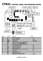
DESCRIPTION OF DIP SWITCHES<br />
The DIP switches control the general functions of the installation:<br />
• Automatic closing or default<br />
• Dead man's operating mode<br />
• Electric lock function<br />
• Response of light barrier<br />
DIP switch 1 ON Automatic closing<br />
OFF Default<br />
DIP switch 2 ON Dead man's operating mode<br />
OFF Default<br />
DIP switch 3 ON Electric lock function<br />
OFF Default<br />
DIP switch 4 ON Light barrier (for closing) stops the<br />
gate/door<br />
OFF Default light barrier (for closing)<br />
opens the gate/door<br />
DESCRIPTION OF POTENTIOMETER<br />
• Force M1 Force M2:<br />
Adjust the force with which the door operates for each wing<br />
separately. The rotary potentiometer is used to make fine gate/door<br />
adjustments.<br />
Should the force generated by the moving wing at its closing<br />
edge exceed 400 N, additional safety features (IR sensors,<br />
contact strips) must be fitted. Any safety features fitted must<br />
comply with the appropriate standards (Europe: EN60335-1).<br />
See 'Safety Rules' section too.<br />
• PAUSE<br />
This function is only active if DIP switch 1 is set to ON. It adjusts<br />
the time for which the gate/door is kept open before it closes again.<br />
Adjustable: 8-200 seconds.<br />
• OPEN-CLOSED<br />
Adjust the maximum running time of the wings. Set the running time<br />
to approx. 30% and then test. Correct adjustment is obtained when<br />
the drive continues to run (hum) against the end stop for 3-5<br />
seconds each time in one complete cycle. This is necessary<br />
because the required running time is affected by external influences<br />
and it must be ensured that the end position is reliably reached<br />
(wind, temperature, changes in ground conditions). This is why end<br />
stops in the OPEN and CLOSE directions are stipulated as being<br />
mandatory.<br />
Adjustable: 7-60 seconds<br />
• WING DELAY<br />
Controls the wing delay in the case of installations with overlapping<br />
wings. Wing M1 opens first and closes last. A delay must always be<br />
set in order to make sure that no one can trap themselves between<br />
two closing wings.<br />
Adjustable: 0-35 seconds<br />
2-GB