Int. Service (+49) 6838/907 172 für Service 06838/907 ... - Nothnagel
Int. Service (+49) 6838/907 172 für Service 06838/907 ... - Nothnagel
Int. Service (+49) 6838/907 172 für Service 06838/907 ... - Nothnagel

Create successful ePaper yourself
Turn your PDF publications into a flip-book with our unique Google optimized e-Paper software.
ELECTRONIC CONTROL<br />
The control board should be the last item to be connected, i.e.<br />
mounting the motors, laying the necessary cable and fitting light barriers<br />
or contact strips. If installation is to be performed in a permanent<br />
location, a means of disconnecting the equipment from the mains<br />
supply with a contact clearance of at least 3 mm is needed (master<br />
switch).<br />
Please note: in these instructions, relay contacts are designated NC<br />
(normal closed) or NO (normal open).<br />
• NC contacts are closed and open<br />
• NO contacts are open and close<br />
Humidity and water will destroy the control board. Always make sure<br />
that water, humidity and condensation cannot enter the control box. It<br />
is vitally important that all openings and cable glands are sealed so<br />
that they are watertight.<br />
ELECTRICAL INSTALLATION<br />
Installing the electronic control board: the motor control board is a<br />
microprocessor-controlled electronic appliance featuring state-of-theart<br />
technology. It is equipped with all the connecting options and<br />
functions needed to guarantee safe operation. The control box<br />
incorporating the motor control board should be installed with the<br />
cable intakes pointing downwards. It should not be continuously<br />
exposed to direct sunlight. The electronic equipment enables the pull<br />
and push forces to be set with great accuracy. If installed and set<br />
correctly, the gate/door can be stopped manually. When in motion,<br />
the gate/door can be stopped at any time by operating the remote<br />
control, the push-button or the key-operated switch.<br />
The gate/door wing must be fitted with a robust end stop for the<br />
'OPEN' and 'CLOSED' positions as the gate/door drive has no<br />
limit switches.<br />
Current distribution: the cable leading from the drive arm must be<br />
laid in a standard watertight distribution box. A permanently installed<br />
cable can be laid from the distribution box to the control unit. It is<br />
often possible to wire the drive, which is fixed beside the control unit<br />
directly to the box. Never install distribution boxes underground.<br />
Generally speaking, the following minimum cable crosssectional<br />
areas must be adhered to:<br />
100-230Volt 1.5mm2 or more<br />
0-24Volt 0.5mm2 or more<br />
Tips: Bell wire is often problematic in practical use because it loses<br />
too much voltage if long lengths of wire are used.<br />
Segregate the cables in cable trunking, i.e. motor cable and light<br />
barrier cable, especially in the case of key-operated switches and<br />
ON switches (from the house wiring system) to prevent interference<br />
where long lengths of cable are used.<br />
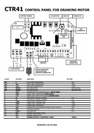
OVERVIEW OF CONNECTIONS<br />
Motors: connect the control unit exactly in accordance with the<br />
overview of connections. The gate/door wing, which opens first, must<br />
be motor 1 (M1) and when it first moves it must OPEN the gate/door.<br />
If it closes the gate/door, swap terminal 6 with terminal 8 or, in the<br />
case of motor 2 (M2), swap terminal 9 with terminal 11.<br />
The capacitor supplied as standard must be installed between<br />
cables 6 and 8 and 9 and 11 (for space reasons, the capacitor can<br />
also be installed in a distribution box). Make sure that its terminals<br />
are properly connected and that there is a good electrical<br />
connection. The capacitor determines the force which the motor<br />
subsequently develops.<br />
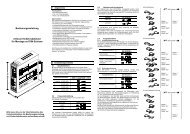
OVERVIEW OF CONNECTIONS<br />
Description of terminal occupancy<br />
Mains cable connection:<br />
Terminal 1 N (blue)<br />
Terminal 2 PE (green/yellow)<br />
Terminal 3 L1 - 230 V (black)<br />
Flashing lamp connection:<br />
Terminal 4 N<br />
Terminal 5 L1 (230V)<br />
Motor connections:<br />
First motor (M1):<br />
Terminal 6 M1 direction of OPEN (brown/black)<br />
(+ capacitor)<br />
Terminal 7 N (blue)<br />
Terminal 8 M1 direction of CLOSED (black/brown)<br />
(+ capacitor)<br />
Second motor (M2):<br />
Terminal 9 M2 direction of OPEN (black/brown)<br />
(+ capacitor)<br />
Terminal 10 N (blue)<br />
Terminal 11 M2 direction of CLOSED (brown/black)<br />
(+ capacitor)<br />
Infrared light barrier<br />
Terminal 12 photocell (NC) active when closing<br />
Terminal 13 COM<br />
Terminal 14 photocell (NC) active when opening<br />
(without light barrier - jumper between 12, 13 & 14!)<br />
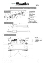
Description of terminal occupancy<br />
EMERGENCY STOP FUNCTION<br />
Terminal 15 COM<br />
Terminal 16 Stop (NC) with emergency stop<br />
switch jumper between 15 and 16<br />
Control line connection<br />
Terminal 17 External push-button (NO) motor 1 (ped. function)<br />
Terminal 15 COM<br />
Terminal 18 External push-button (NO) motors 1+2<br />
Electric lock connection<br />
Terminal 19 Distribution voltage 12 V AC<br />
Terminal 20 Distribution voltage 12 V AC<br />
Connection for additional equipment & light barrier<br />
Terminal 21 Distribution voltage 24 V AC (500 mA max.)<br />
Terminal 22 Distribution voltage 24 V AC<br />
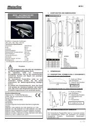
DESCRIPTION OF JUMPER<br />
JP1: MOTOR<br />
OPEN: (without jumper): only for single-wing gates<br />
(only motor 1 operating).<br />
CLOSED: (with jumper): only for double-wing gates<br />
(motors 1 and 2 operating).<br />
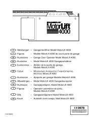
JP2: channel 2 radio receiver<br />
If both learning channels are put together (A-side), the memory<br />
capacity of the radio receiver doubles in size. The gate can then only<br />
be fully opened. The "Pedestrian" function is no longer available. Aside:<br />
(optional) receiver channel 2 is connected up to receiver<br />
channel 1.<br />
B-side: (standard) the two radio receiver channels work separately<br />
from one another.<br />
JP2<br />
A B<br />
1-GB