Int. Service (+49) 6838/907 172 für Service 06838/907 ... - Nothnagel
Int. Service (+49) 6838/907 172 für Service 06838/907 ... - Nothnagel
Int. Service (+49) 6838/907 172 für Service 06838/907 ... - Nothnagel

Create successful ePaper yourself
Turn your PDF publications into a flip-book with our unique Google optimized e-Paper software.
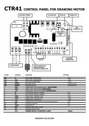
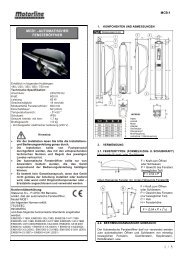
DESCRIPTION OF LEDS<br />
LED 1 red Monitors the light barrier for door closing. LED<br />
ON = OK<br />
LED 2 red Monitors the light barrier for door opening LED<br />
ON = OK<br />
LED 3 yellow Monitors the emergency stop contact ON=OK<br />
LED 4 green Indicates signals from key-operated switches,<br />
push-buttons or radio. Single-wing gate/door<br />
opening function ON = signal present.<br />
LED 5 green Indicates signals from key-operated switches,<br />
push-buttons or radio. Both-wing gate/door<br />
opening function ON = signal present.<br />
LED 6 red Flashes slowly = OK<br />
Flashes quickly = check all connections to the<br />
motors, capacitor, flashing lamp and remove any<br />
humidity from terminals.<br />
DESCRIPTION OF FUSES<br />
F1 5.0A Main fuse: Protects the entire control unit and the<br />
motors. Never replace this fuse by one with a<br />
higher rating.<br />
F2 0,5A Secondary fuse for 24 V output.<br />
F3 2,0A Secondary fuse for electric lock 12 V output. Please<br />
bear in mind the power requirement of the electric<br />
lock you use.<br />
F4 0,315A Secondary fuse for logic circuitry: push-buttons,<br />
emergency stop, light barrier, receiver.<br />
TEACHING THE REMOTE CONTROL<br />
Up to 15 remote controls can be programmed on each self-learn<br />
channel. In the case of large installations it is advisable for<br />
organizational reasons, to use an external receiver or a key-operated<br />
switch or a code lock, which should be installed at the entrance.<br />
The radio receiver plugs in on the side and has two small self-learn<br />
buttons.<br />
The radio remote control is licensed by the Post + Telecommunication<br />
Office and costs nothing to operate. It works on the basis of a private<br />
security code (approx. 3.5 billion code options) that is pre-programmed<br />
via computer. Your gate/door drive can thus only be activated by a<br />
correspondingly coded handset. The range obtained depends on the<br />
given local environment. The receiver element of the motor control has<br />
an integrated self-learn function. It can be set to the handset's preprogrammed<br />
code by pressing the self-learn push-button.<br />
The control unit has two self-learn channels and is therefore able to<br />
open or close one gate/door or both gates/doors simultaneously via<br />
appropriate operation of the handset. Should, for instance, channel 1 (2)<br />
receive the handset's remote control code, only one wing will be<br />
opened. If you teach the remote control on channel 2 (1), you will be<br />
able to open both wings via the appropriate push-button. To memorize<br />
the code all you need do is press the button of your choice on the<br />
handset and keep it depressed while, at the same time, briefly pressing<br />
the self-learn button on the electronic unit with the other hand. Repeat<br />
this procedure for all other transmitters.<br />
DELETION OF REMOTE CONTROL CODE<br />
Press the appropriate self-learn button (1 or 2) on the receiver<br />
control board for approx. 10 seconds until the self-learn LED<br />
extinguishes. The codes previously 'learned' allocated to the given<br />
self-learn button have thus been deleted.<br />
709236-GB © Chamberlain GmbH, 2003<br />
REPROGRAMMING<br />
For reprogramming purposes, the coding procedure mentioned<br />
above should be repeated for all the remote controls in use and/or<br />
their appropriate operating buttons.<br />
The radio remote control's range varies according to the given local<br />
environment. Keep the push-button on the handset depressed until<br />
such time (approx. 2 seconds) as the gate/door is seen to move.<br />
Your radio remote control is digitally coded, i.e. accidental operation<br />
of the gate/door drive is more or less impossible.<br />
INITIAL OPERATION<br />
Proceed carefully and deliberately. Do not rush the process of<br />
making the basic settings. It may take up to 30 minutes to complete<br />
initial settings. If applicable get help from a second person so that<br />
changes on the control unit can be made more easily (power OFF or<br />
ON).<br />
1. Connect the control unit including the safety inputs.<br />
2. Check the LEDs.<br />
3. Move the gate/door to a half-opened position and engage it, then<br />
press the test button. Both wings must then open. If one wing<br />
closes instead of opening, the terminals on the given wing's<br />
motor have been connected incorrectly and the motor cables for<br />
the relevant motor must be swapped round (see connections).<br />
The cables to which the capacitor is also connected are the ones<br />
that need to be swapped round. They determine the direction in<br />
which the motors run. Then repeat the entire process until both<br />
wings open when they first move. Important, always switch the<br />
power off to do this.<br />
4. If both wings open when they first move once the control unit has<br />
been connected, proceed as follows.<br />
5. <strong>Int</strong>errupt the power supply to the control unit and reconnect it<br />
after a few seconds. Close both gate/door wings manually and<br />
engage both wings.<br />
6. Adjust all the potentiometers to 30% and make sure that DIP<br />
switch 1 is set to OFF (down).<br />
7. Then use the test button to switch on the control unit and<br />
observe what happens. Close the gate/door again by using the<br />
test button WITHOUT having made any adjustments to the<br />
settings. If the gate/door does not close completely by itself,<br />
release the drive and close it manually after switching off the<br />
control unit.<br />
8. Then adjust the potentiometer to a different (higher) value in line<br />
with the value suggested by practical experience from trial<br />
operation (e.g. increase running time, correct force, wing delay).<br />
Then make a second trial and repeat the procedure above<br />
closing the gate/door first with the test button before making any<br />
further settings.<br />
9. Once all settings have been made, check that the light barriers,<br />
push-buttons, flashing lamp, handset, accessories etc. function<br />
correctly. If you require automatic closing, modify the setting of<br />
the DIP switches and adjust the potentiometer for a pause.<br />
10. Show anyone who has to deal with the gate/door how the<br />
gate/door moves, how the safety functions operate and how the<br />
drive can be actuated manually.<br />
Declaration of Conformity<br />
Control unit for ...........................................................................................CB1<br />
is in conformity to the applicable sections of<br />
Standards...............................................EN300220-3, EN55014, EN61000-3,<br />
............................................................ETS 300 683, EN60555, & EN60335-1<br />
per the provisions & all amendments of<br />
EU Directives .............................................................73/23/EEC, 89/336/EEC<br />
Declaration of Incorporation<br />
Control unit CB1 meets, when installed and maintained according to all<br />
the manufacturer's instructions, the provisions of EU Directive<br />
89/392/EEC and all amendments.<br />
I, the undersigned, hereby declare that the equipment specified above<br />
and any accessory listed in the manual conforms to the<br />
above Directives and Standards<br />
Chamberlain GmbH<br />
D-66793 Saarwellingen<br />
January, 2003 Colin B. Willmott<br />
Chief Engineer<br />
GB-3