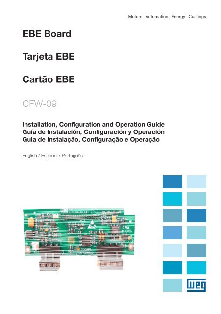
EBE Board Tarjeta EBE Cartão EBE CFW-09 - Weg
EBE Board Tarjeta EBE Cartão EBE CFW-09 - Weg
EBE Board Tarjeta EBE Cartão EBE CFW-09 - Weg
Create successful ePaper yourself
Turn your PDF publications into a flip-book with our unique Google optimized e-Paper software.
<strong>EBE</strong> <strong>Board</strong><br />
<strong>Tarjeta</strong> <strong>EBE</strong><br />
<strong>Cartão</strong> <strong>EBE</strong><br />
<strong>CFW</strong>-<strong>09</strong><br />
Installation, Configuration and Operation Guide<br />
Guía de Instalación, Configuración y Operación<br />
Guia de Instalação, Configuração e Operação<br />
English / Español / Português<br />
Motors | Automation | Energy | Coatings
SUMMARY<br />
Summary<br />
I SAFETY NOTICES .......................................................................................5<br />
II GENERAL INFORMATION ..........................................................................5<br />
III PACKAGE CONTENT .................................................................................5<br />
1 <strong>EBE</strong> BOARD INSTALLATION ......................................................................5<br />
2 CONFIGURATIONS .....................................................................................6<br />
3 GROUNDING ................................................................................................6<br />
4 RS-485 INTERFACE CONNECTION ..........................................................7<br />
5 TECHNICAL SPECIFICATIONS ..................................................................8<br />
ÍNDICE<br />
I INFORMACIONES DE SEGURIDAD............................................................9<br />
II INFORMACIONES GENERALES ................................................................9<br />
III CONTENIDO DEL EMBALAJE ..................................................................9<br />
1 INSTALACIÓN DE LA TARJETA <strong>EBE</strong> .........................................................9<br />
2 CONFIGURACIONES ................................................................................ 10<br />
3 PUESTA A TIERRA .................................................................................... 10<br />
4 CONEXIÓN DE LA SERIAL RS-485 ......................................................... 11<br />
5 ESPECIFICACIONES TÉCNICAS ............................................................. 12
Summary<br />
ÍNDICE<br />
I INFORMAÇÕES DE SEGURANÇA ............................................................ 13<br />
II INFORMAÇÕES GERAIS .......................................................................... 13<br />
III CONTEÚDO DA EMBALAGEM ............................................................... 13<br />
1 INSTALAÇÃO DO CARTÃO <strong>EBE</strong> ............................................................... 13<br />
2 CONFIGURAÇÕES .................................................................................... 14<br />
3 ATERRAMENTO ........................................................................................ 14<br />
4 CONEXÕES DA SERIAL RS-485 .............................................................. 15<br />
5 ESPECIFICAÇÕES TÉCNICAS ................................................................. 16
I SAFETY NOTICES<br />
<strong>EBE</strong> Expansion <strong>Board</strong><br />
ATTENTION!<br />
WARNING: NEVER touch any of the electrical components directly when<br />
the equipment is removed from the package.<br />
The serial interface RS-485 can not be used simultaneously with the serial<br />
interface RS-232 .<br />
II GENERAL INFORMATION<br />
This guide provides information for the correct installation, configuration and operation of<br />
<strong>EBE</strong> <strong>Board</strong> in the <strong>CFW</strong>-<strong>09</strong>.<br />
III PACKAGE CONTENT<br />
1 Expansion <strong>Board</strong> packaged in anti-static package.<br />
NOTE!<br />
Check if the model indicated in the label on the package is exactly the<br />
model requested.<br />
Remove the Expansion board from the anti-static plastic package carefully.<br />
Hold the board only on the sides. Do not touch directly on the components.<br />
1 <strong>EBE</strong> BOARD INSTALLATION<br />
The <strong>EBE</strong> board is installed directly on the CC9 control board and fixed through standoffs.<br />
The connection with the CC9 board is done via the XC11 (24V supply for the expansion<br />
board) and XC3 connectors.<br />
For installing the board, follow the guidelines bellow:<br />
Step 1: With the frequency inverter not energized, remove the <strong>CFW</strong>-<strong>09</strong> frontal cover;<br />
Step 2: If the inverter is Size 1, also remove the lateral cover;<br />
Step 3: Carefully insert terminal block XC3 into the female connector XC3 on the CC9<br />
control board;<br />
Step 4: Check if all pins of the XC3 connector are connected correctly;<br />
Step 5: Press on the <strong>EBE</strong> board center (near XC3) and on the left top edge until the<br />
complete insertion of the connector and plastic spacer;<br />
Step 6: Fix the board to the 2 metallic spacers with the 2 screws provided;<br />
Step 7: Plug the XC11 cable connector of the expansion board to the XC11 connector<br />
of the control board CC9.<br />
<strong>EBE</strong> | 5<br />
English
English<br />
<strong>EBE</strong> Expansion <strong>Board</strong><br />
Figure 1.1: XC3 <strong>EBE</strong> connector<br />
insertion - Front view<br />
2 CONFIGURATIONS<br />
6 | <strong>EBE</strong><br />
Figure 1.2: XC11 - <strong>EBE</strong><br />
connector insertion - Top view<br />
PTC - Set parameter P270 to 16 (Motor Thermistor).<br />
RS-485 - Set parameters P308 and P312.<br />
Table 2.1: <strong>EBE</strong> board selector switches configurations<br />
Figure 1.3: <strong>EBE</strong> Bolt insertion -<br />
Side view<br />
Switch Function OFF ON<br />
S1:1 RS-485 B-LINE (+) without<br />
with<br />
S1:2 RS-485 A-LINE (-) termination*<br />
termination<br />
* Factors default.<br />
3 GROUNDING<br />
NOTE!<br />
For addtional information, please, refer to the <strong>CFW</strong>-<strong>09</strong> manual (WEG Serial<br />
Communication and Modbus RTU).<br />
Digital signals - The cable shield must be connected to the protection ground of the<br />
<strong>CFW</strong>-<strong>09</strong> frame.<br />
Analog signals - The cable shield must be connected on the side of the device (sensors,<br />
PLC analog inputs and outputs, etc.). In these cases the manufacturer recommendations<br />
must to be respected.<br />
ATTENTION!<br />
The cable specifications and ground connections must be fulfilled for<br />
ensuring the correct board operation.<br />
The device ground point must be the same of the inverter grounding.<br />
Differences on grounding generates voltage differences that cause<br />
interferences in the analog signals.
<strong>EBE</strong> Expansion <strong>Board</strong><br />
The digital input DI8 includes a special function for motor thermistor (PTC) measure ment.<br />
To use this function, the mounting presented in the figure 3.1 must be done.<br />
Figure 3.1: Connection and operation of the digital input DI8 with motor thermistor function<br />
(P270 = 16)<br />
To use DI8 as a normal digital input, a resistor must be inserted, as indicated in the figure<br />
3.2.<br />
Figure 3.2: DI8 connection to be used as a digital input (any P270 function, except 16)<br />
4 RS-485 INTERFACE CONNECTION<br />
1) Line termination: include line termination only at the network ends.<br />
2) Recommended cable: cable shielding to operate with different signals (ex.: AFS series<br />
from KMP, etc.).<br />
3) Grounding of the cable shield: connect the shielding to the equipment frame.<br />
Figure 4.1: <strong>CFW</strong>-<strong>09</strong> network connection through RS-485 serial interface<br />
Ω<br />
<strong>EBE</strong> | 7<br />
English
English<br />
<strong>EBE</strong> Expansion <strong>Board</strong><br />
5 TECHNICAL SPECIFICATIONS<br />
The technical specifications of all factories default functions provided by <strong>EBE</strong> board is<br />
shown at table 5.1.<br />
Table 5.1: Factory default Function description and technical specifications of <strong>EBE</strong> board and the<br />
respective position to the XC2 and XC5 connectors<br />
Connector Pin Signal Description/Specification<br />
Digital Input for special motor thermistor function,<br />
1 DI8 programmable in P270<br />
XC5<br />
Connection according to the figures 4 or 5<br />
2 DGND DGND internally grounded by a 249 Ω resistor<br />
3 - Not connected<br />
4 A-LINE Isolated RS-485 serial port - A - LINE (-)<br />
XC2<br />
5<br />
6<br />
B-LINE<br />
SREF<br />
Isolated RS-485 serial port - B - LINE (+)<br />
Reference to RS-485<br />
7 GROUND Ground (Inverter cabinet)<br />
8 | <strong>EBE</strong>
I INFORMACIONES DE SEGURIDAD<br />
<strong>Tarjeta</strong> de Expansión <strong>EBE</strong><br />
ATENCIÓN!<br />
CUIDADO al sacar el producto de la embalaje - NO toque directamente<br />
en los componentes electrónicos.<br />
La comunicación serial RS-485 no puede ser utilizada junto con la<br />
comunicación serial RS-232.<br />
II INFORMACIONES GENERALES<br />
Este guía orienta como instalar, configurar y operar las <strong>Tarjeta</strong>s <strong>EBE</strong> para el <strong>CFW</strong>-<strong>09</strong>.<br />
III CONTENIDO DEL EMBALAJE<br />
1 tarjeta de expansión de funciones en embalaje antiestatica.<br />
NOTA!<br />
Verifique si el modelo descripto en la etiqueta contenida es el modelo<br />
solicitado.<br />
Sacar la tarjeta del plástico antiestático con cuidado.<br />
Cojer la tarjeta por la lateral y no toque directamente en los componentes.<br />
1 INSTALACIÓN DE LA TARJETA <strong>EBE</strong><br />
La tarjeta <strong>EBE</strong> es instalada directamente sobre la tarjeta de control CC9 y fijado por<br />
espaciadores. La conexión de la tarjeta CC9 es hecha vía conectores XC11 (alimentación<br />
de 24 V para la tarjeta de expansión) y XC3.<br />
Para la instalación siga los pasos abajo:<br />
Paso 1: Con el convertidor desenergizado, sacar la tapa frontal del <strong>CFW</strong>-<strong>09</strong>;<br />
Paso 2: Si el modelo del suyo convertidor es del tamaño 1, sacar también la tapa<br />
lateral;<br />
Paso 3: Encaje cuidadosamente el conector XC3 en el conector hembra XC3 de la tarjeta<br />
de control CC9;<br />
Paso 4: Verifique se todos los terminales del conector XC3 están correctamente<br />
enchufados;<br />
Paso 5: Presione el centro de la tarjeta (próximo a XC3) y en el canto superior izquierdo<br />
hasta el completo encaje del conector y del espaciador plástico;<br />
Paso 6: Fije la tarjeta a los 2 espaciadores metálicos a través de los 2 tornillos;<br />
Paso 7: Encaje el cable que conecta el conector XC11 de la tarjeta de expansión al<br />
conector XC11 de la tarjeta de controle CC9.<br />
<strong>EBE</strong> | 9<br />
Español
Español<br />
<strong>Tarjeta</strong> de Expansión <strong>EBE</strong><br />
Figura 1.1: Encaje del conector<br />
XC3 <strong>EBE</strong> - Vista frontal<br />
2 CONFIGURACIONES<br />
10 | <strong>EBE</strong><br />
Figura 1.2: Encaje del conector<br />
XC11 - <strong>EBE</strong> - Vista superior<br />
PTC - Programar el P270 para opción 16 (Termistor del Motor).<br />
RS-485 - Configurar P308 y P312.<br />
* Padrón.<br />
Figura 1.3: Encaje de los tornillos<br />
<strong>EBE</strong> - Vista lateral<br />
Tabla 2.1: Configuraciones - conector de selección de la tarjeta <strong>EBE</strong><br />
Conector Función OFF ON<br />
S1:1 RS-485 B-LINE (+) sin<br />
con<br />
S2:2 RS-485 A-LINE (-) terminación* terminación<br />
NOTA!<br />
Informaciones adicionales consultar el manual <strong>CFW</strong>-<strong>09</strong> (Comunicación<br />
Serial WEG y Modbus RTU).<br />
3 PUESTA A TIERRA<br />
Señales digitales - La blindaje del cable debe ser conectada al tierra de protección<br />
en la carcaza del <strong>CFW</strong>-<strong>09</strong>.<br />
Señales analógicos - La blindaje del cable debe ser conectada del lado del dispositivo<br />
(sensores, entradas y salidas analógicas de PLC, etc.). En ese caso se debe seguir las<br />
recomendaciones del fabricante del dispositivo.<br />
ATENCIÓN!<br />
Las especificaciones de los cables y conexión de puesta a tierra son<br />
indispensables para el correcto funcionamiento de la tarjeta.<br />
Es importante que el punto de puesta a tierra del convertidor y del<br />
dispositivo sea el mismo. Diferenciales de tierra entre equipamientos<br />
generan diferencias de tensión que provocan interferencias en los señales<br />
analógicos.
<strong>Tarjeta</strong> de Expansión <strong>EBE</strong><br />
La entrada digital DI8 posee una función especial para medición de termistores. Para usar<br />
esta función débese realizar la montaje presentada en la figura 3.1.<br />
Figura 3.1: Conexión y funcionamiento de la entrada digital DI8 con la función termistor del motor<br />
(P270 = 16)<br />
Para utilizar la DI8 como entrada digital común débese inserir un resistor conforme las<br />
especificaciones de la figura 3.2.<br />
a<br />
Figura 3.2: Conexión de la DI8 como entrada digital (cualquier función en P270 excepto la 16)<br />
4 CONEXIÓN DE LA SERIAL RS-485<br />
1) Terminación de línea: Incluir puesta a tierra de la línea solamente en los extremos de la<br />
red;<br />
2) Cable recomendado: Cable mallado para operación con señales diferenciales<br />
(ex.: línea AFS, fabricante KMP);<br />
3) Puesta a tierra de la blindaje de los cables: Conectar en la carcaza del equipamiento.<br />
Figura 4.1: Conexión del <strong>CFW</strong>-<strong>09</strong> en red vía RS-485<br />
Ω<br />
<strong>EBE</strong> | 11<br />
Español
Español<br />
<strong>Tarjeta</strong> de Expansión <strong>EBE</strong><br />
5 ESPECIFICACIONES TÉCNICAS<br />
Las especificaciones técnicas de todas las funciones existentes en la tarjeta <strong>EBE</strong> son<br />
presentadas en la tabla 5.1.<br />
Tabla 5.1: Descripción y especificación técnica de las funciones presentes en la tarjeta <strong>EBE</strong> y sus<br />
respectivos terminal (conector XC2 y XC5)<br />
Conectador Terminal Señal Descripción / Especificación<br />
Entrada digital con función especial para termistor,<br />
1 DI8 programable em P270<br />
Conexión conforme figuras 4 o 5<br />
XC5<br />
2 DGND<br />
DGND puesta a tierra internamente a través de un<br />
resistor 249 Ω<br />
XC2<br />
12 | <strong>EBE</strong><br />
3 - No conectar<br />
4 A-LINE Serial RS-485 - Aislada - A - LINE (-)<br />
5 B-LINE Serial RS-485 - Aislada - B - LINE (+)<br />
6 SREF Referencia para RS-485<br />
7 TIERRA Tierra (Cuadro eléctrico del convertidor)
I INFORMAÇÕES DE SEGURANÇA<br />
<strong>Cartão</strong> de Expansão <strong>EBE</strong><br />
ATENCÃO!<br />
CUIDADO ao retirar o produto da embalagem: NÃO toque diretamente<br />
nos componentes.<br />
A comunicação serial RS-485 não pode ser utilizada juntamente com a<br />
comunicação serial RS-232.<br />
II INFORMAÇÕES GERAIS<br />
Esse guia orienta como instalar, configurar e operar o <strong>Cartão</strong> <strong>EBE</strong> para o <strong>CFW</strong>-<strong>09</strong>.<br />
III CONTEÚDO DA EMBALAGEM<br />
1 cartão de expansão de funções em embalagem anti-estática.<br />
NOTA!<br />
Verifique se o modelo descrito na etiqueta contida na embalagem é o<br />
modelo solicitado.<br />
Retire o cartão do plástico anti-estático com cuidado.<br />
Pegue o cartão pela lateral e não toque diretamente nos componentes.<br />
1 INSTALAÇÃO DO CARTÃO <strong>EBE</strong><br />
O cartão <strong>EBE</strong> é instalado diretamente sobre o cartão de controle CC9 e fixado por<br />
espaçadores. A conexão com o cartão CC9 é feita via conectores XC11 (alimentação de<br />
24 V para o cartão de expansão) e XC3.<br />
Para instalação siga os passos abaixo:<br />
Passo 1: Com o inversor desenergizado, retire a tampa frontal do <strong>CFW</strong>-<strong>09</strong>;<br />
Passo 2: Se o modelo do seu inversor for da Mecânica 1 retire também a tampa lateral;<br />
Passo 3: Encaixe cuidadosamente o conector barra de pinos XC3 no conector fêmea<br />
XC3 do cartão de controle CC9;<br />
Passo 4: Verifique se todos os pinos do conector XC3 estão corretamente conectados;<br />
Passo 5: Pressione o centro do cartão (próximo a XC3) e o canto superior esquerdo até<br />
o completo encaixe do conector e do espaçador plástico;<br />
Passo 6: Fixe o cartão aos 2 espaçadores metálicos através dos 2 parafusos;<br />
Passo 7: Encaixe o cabo que liga o conector XC11 do cartão de expansão ao conector<br />
XC11 do cartão de controle CC9.<br />
<strong>EBE</strong> | 13<br />
Português
Português<br />
<strong>Cartão</strong> de Expansão <strong>EBE</strong><br />
Figura 1.1: Encaixe do conector Figura 1.2: Encaixe do conector<br />
XC3 <strong>EBE</strong> - Vista frontal XC11 <strong>EBE</strong> - Vista superior<br />
2 CONFIGURAÇÕES<br />
PTC - Programe P270 para opção 16 (Termistor do Motor).<br />
RS-485 - Configure P308 e P312.<br />
* Padrão.<br />
14 | <strong>EBE</strong><br />
Tabela 2.1: Configuração - chaves de seleção do cartão <strong>EBE</strong><br />
Figura 1.3: Encaixe dos<br />
parafusos <strong>EBE</strong> - Vista lateral<br />
Chave Função OFF ON<br />
S1:1 RS-485 B-LINE (+) sem<br />
com<br />
S2:2 RS-485 A-LINE (-) terminação*<br />
terminação<br />
3 ATERRAMENTO<br />
NOTA!<br />
Informações adicionais consulte o manual <strong>CFW</strong>-<strong>09</strong> (Comunicação Serial<br />
WEG e Modbus RTU).<br />
Sinais digitais - A blindagem do cabo deve ser conectada ao terra de proteção na<br />
carcaça do <strong>CFW</strong>-<strong>09</strong>.<br />
Sinais analógicos - A blindagem do cabo deve ser conectada do lado do dispositivo<br />
(sensores, entradas e saídas analógicas de PLC, etc.). Nesse caso devem-se seguir as<br />
recomendações do fabricante do dispositivo.<br />
ATENÇÃO!<br />
As especificações dos cabos e conexões de aterramento são<br />
indispensáveis para o correto funcionamento do seu cartão.<br />
É importante que o ponto de aterramento do inversor e do dispositivo<br />
seja o mesmo.<br />
Diferenças de terra entre equipamentos geram diferenças de tensão que<br />
provocam interferências nos sinais analógicos.
<strong>Cartão</strong> de Expansão <strong>EBE</strong><br />
A entrada digital DI8 possui uma função especial para medição de termistores. Para utilizar<br />
esta função deve-se realizar a montagem apresentada na Figura 3.1.<br />
Figura 3.1: Conexão e funcionamento da entrada digital DI8 com função termistor do motor<br />
(P270 = 16)<br />
Para utilizar a DI8 como entrada digital comum deve-se inserir um resistor conforme as<br />
especificações da figura 3.2.<br />
a<br />
Figura 3.2: Conexão da DI8 como entrada digital (qualquer função em P270 exceto a 16)<br />
4 CONEXÕES DA SERIAL RS-485<br />
1) Terminação de linha: Incluir terminação da linha apenas nos extremos da rede;<br />
2) Cabo recomendado: Cabo blindado para operação com sinais diferentes (ex.: linha<br />
AFS, fabricante KMP);<br />
3) Aterramento da blindagem dos cabos: Conectar na carcaça do equipamento.<br />
Figura 4.1: Conexão do <strong>CFW</strong>-<strong>09</strong> em rede via RS-485<br />
Ω<br />
<strong>EBE</strong> | 15<br />
Português
Português<br />
<strong>Cartão</strong> de Expansão <strong>EBE</strong><br />
5 ESPECIFICAÇÕES TÉCNICAS<br />
As especificações técnicas de todas as funções existentes no cartão <strong>EBE</strong> são apresentadas<br />
na tabela 5.1.<br />
Tabela 5.1: Descrição e especificação técnica das funções presentes no cartão <strong>EBE</strong> e respectiva<br />
pinagem para os conectores XC2 e XC5<br />
Conector Pino Sinal Descrição / Especificação<br />
XC5<br />
XC2<br />
16 | <strong>EBE</strong><br />
1 DI8<br />
2 DGND<br />
Entrada digital com função especial para termistor,<br />
programável em P270<br />
Conexão conforme figuras 4 ou 5<br />
DGND aterrado internamente através de um resistor<br />
de 249 Ω<br />
3 - Não conectar<br />
4 A-LINE Serial RS - 485 - Isolada - A - LINE (-)<br />
5 B-LINE Serial RS - 485 - Isolada - B - LINE (+)<br />
6 SREF Referência para RS-485<br />
7 TERRA Terra (Gabinete do inversor)
WEG Automação S.A.<br />
Jaraguá do Sul - SC - Brazil<br />
Phone 55 (47) 3276-4000 - Fax 55 (47) 3276-4020<br />
0899.5192/02<br />
São Paulo - SP - Brazil<br />
Phone 55 (11) 5053-2300 - Fax 55 (11) 5052-4212<br />
automacao@weg.net<br />
www.weg.net Document:


