Hormigones de alta resistencia en la edificación de gran ... - ACHE
Hormigones de alta resistencia en la edificación de gran ... - ACHE
Hormigones de alta resistencia en la edificación de gran ... - ACHE

You also want an ePaper? Increase the reach of your titles
YUMPU automatically turns print PDFs into web optimized ePapers that Google loves.
<strong>Hormigones</strong> <strong>de</strong> <strong>alta</strong> <strong>resist<strong>en</strong>cia</strong><br />
<strong>en</strong> <strong>la</strong> <strong>edificación</strong> <strong>de</strong> <strong>gran</strong> altura<br />
Aplicación particu<strong>la</strong>r al Edificio Torre Espacio<br />
<strong>en</strong> el Paseo <strong>de</strong> <strong>la</strong> Castel<strong>la</strong>na Madrid<br />
Specific application to the Torre Espacio Building<br />
in the Paseo <strong>de</strong> <strong>la</strong> Castel<strong>la</strong>na in Madrid<br />
Specific application to the Torre Espacio Building<br />
in the Paseo <strong>de</strong> <strong>la</strong> Castel<strong>la</strong>na in Madrid<br />
RESUMEN<br />
La utilización <strong>de</strong> los hormigones <strong>de</strong> <strong>alta</strong> <strong>resist<strong>en</strong>cia</strong> <strong>en</strong> <strong>la</strong>s<br />
estructuras <strong>de</strong> <strong>edificación</strong> <strong>de</strong> <strong>gran</strong> altura ha experim<strong>en</strong>tado un<br />
notable increm<strong>en</strong>to <strong>de</strong>bido a <strong>la</strong> idoneidad <strong>de</strong> sus prestaciones<br />
<strong>en</strong> los elem<strong>en</strong>tos portantes verticales, que no se limitan exclusivam<strong>en</strong>te<br />
al aum<strong>en</strong>to <strong>de</strong> <strong>la</strong> capacidad resist<strong>en</strong>te y lo que ello<br />
supone <strong>de</strong> reducción <strong>de</strong> dim<strong>en</strong>siones, volúm<strong>en</strong>es y pesos, sino<br />
también a <strong>la</strong> <strong>gran</strong> mejora que aportan <strong>en</strong> lo refer<strong>en</strong>te a <strong>la</strong> durabilidad<br />
y a los aspectos reológicos.<br />
No obstante, para alcanzar <strong>la</strong> máxima efectividad <strong>de</strong> su<br />
empleo, el proyecto <strong>de</strong> <strong>la</strong> estructura <strong>de</strong>be t<strong>en</strong>er <strong>en</strong> consi<strong>de</strong>ración<br />
los criterios específicos que se seña<strong>la</strong>n, <strong>de</strong> forma <strong>de</strong> evitar<br />
o reducir <strong>la</strong> inci<strong>de</strong>ncia que <strong>la</strong>s <strong>de</strong>formaciones diferidas <strong>de</strong><br />
dichas piezas verticales, aunque mejoradas respecto a <strong>la</strong>s que<br />
se obt<strong>en</strong>drían con hormigones normales, implican <strong>en</strong> <strong>la</strong> respuesta<br />
<strong>de</strong>l sistema a <strong>la</strong>rgo p<strong>la</strong>zo.<br />
La exposición se completa con <strong>la</strong> <strong>de</strong>scripción <strong>de</strong> <strong>la</strong> aplicación<br />
<strong>de</strong> estos hormigones al proyecto <strong>de</strong>l Edificio Torre Espacio<br />
<strong>en</strong> el Paseo <strong>de</strong> <strong>la</strong> Castel<strong>la</strong>na <strong>en</strong> Madrid.<br />
SUMMARY<br />
The use of high str<strong>en</strong>gth concrete in tall buildings has become<br />
increasingly more wi<strong>de</strong>spread due to the suitability of its<br />
characteristics in vertical bearing elem<strong>en</strong>ts. These characteristics<br />
are not purely limited to increase the str<strong>en</strong>gth capacity<br />
and the <strong>en</strong>suing reduction in size, volume and weight, but also<br />
Julio Martínez Calzón<br />
Dr. Ing<strong>en</strong>iero <strong>de</strong> Caminos<br />
MC2 Estudio <strong>de</strong> Ing<strong>en</strong>iería, S.L.<br />
to the great improvem<strong>en</strong>ts re<strong>la</strong>ted to durability and time<br />
<strong>de</strong>p<strong>en</strong><strong>de</strong>nt effects.<br />
However, in or<strong>de</strong>r to <strong>en</strong>sure maximum effectiv<strong>en</strong>ess, the<br />
<strong>de</strong>sign of the structure should take into account the specific<br />
criteria indicated in the paper, in or<strong>de</strong>r to prev<strong>en</strong>t or reduce<br />
the effects that creep in vertical members may have on the<br />
long-term response of the structure, ev<strong>en</strong> though this is very<br />
much improved compared to that obtained from normal concrete.<br />
The paper inclu<strong>de</strong>s a <strong>de</strong>scription of the use of this type of<br />
concrete in the Torre Espacio Building in the Paseo <strong>de</strong> <strong>la</strong> Castel<strong>la</strong>na<br />
in Madrid.<br />
La pres<strong>en</strong>cia <strong>de</strong> los <strong>Hormigones</strong> <strong>de</strong> Alta Resist<strong>en</strong>cia (HAR)<br />
<strong>en</strong> el ámbito <strong>de</strong> <strong>la</strong> construcción <strong>de</strong> edificios ha t<strong>en</strong>ido una<br />
introducción muy acompasada con el avance <strong>de</strong> sus posibilida<strong>de</strong>s<br />
<strong>de</strong> utilización sistemática y económica, y con <strong>la</strong>s condiciones<br />
<strong>de</strong> su a<strong>de</strong>cuada puesta <strong>en</strong> obra, hasta lograr que su<br />
uso pueda consi<strong>de</strong>rarse como si se tratara prácticam<strong>en</strong>te <strong>de</strong> un<br />
hormigón habitual. Actualm<strong>en</strong>te estas condiciones se cumpl<strong>en</strong><br />
y <strong>la</strong> <strong>de</strong>cisión <strong>de</strong> su utilización se establece <strong>en</strong> re<strong>la</strong>ción<br />
con aspectos re<strong>la</strong>cionados muy diversam<strong>en</strong>te con el edificio:<br />
tipología estructural, rapi<strong>de</strong>z <strong>de</strong> ejecución, economía g<strong>en</strong>eralizada,<br />
etc.; pero pue<strong>de</strong> <strong>de</strong>cirse que su utilización resulta muy<br />
competitiva <strong>en</strong> muchas ocasiones para <strong>la</strong> realización <strong>de</strong> los<br />
elem<strong>en</strong>tos verticales <strong>de</strong> <strong>la</strong>s estructuras <strong>de</strong> altura.<br />
Hormigón y Acero núms. 228-229, 2.º y 3er trimestre 2003 5<br />
Hormigón autocompactable
Hormigón autocompactable<br />
J. Martínez<br />
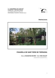
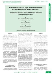
Figura 1. Lake Point Tower, Chicago.<br />
El <strong>de</strong>sarrollo <strong>de</strong> este tipo <strong>de</strong> hormigones: f c ≥ 50 MPa, <strong>en</strong> <strong>la</strong><br />
Edificación <strong>de</strong> Gran Altura (EGA) comi<strong>en</strong>za <strong>en</strong> Chicago<br />
hacia 1970, si<strong>en</strong>do su edificio más repres<strong>en</strong>tativo el Lake<br />
Point Tower (H ≅ 180 m; f c = 55 MPa) (Fig. 1); alcanza un<br />
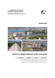
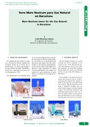
rango muy importante hacia 1990 <strong>en</strong> los edificios <strong>de</strong>l 311<br />
South Wacker Drive (H ≅ 290 m; f c = 84 MPa) (Fig. 2) y Two<br />
Pru<strong>de</strong>ntial P<strong>la</strong>za (H ≅ 275 m; f c = 84 MPa) (Fig. 3) y actualm<strong>en</strong>te,<br />
sali<strong>en</strong>do <strong>de</strong> sus oríg<strong>en</strong>es, sus ejemplos más <strong>de</strong>stacados<br />
son los edificios Two Union Square <strong>en</strong> Seattle (H ≅ 220 m; f c<br />
= 133 MPa) (Fig. 4) <strong>en</strong> cuanto a <strong>resist<strong>en</strong>cia</strong> y <strong>la</strong>s Torres Petronas<br />
<strong>de</strong> Kua<strong>la</strong> Lumpur <strong>en</strong> Ma<strong>la</strong>sia (H ≅ 450 m; f c = 89 MPa)<br />
(Fig. 5) consi<strong>de</strong>rando <strong>la</strong> altura.<br />
<strong>Hormigones</strong> <strong>de</strong> <strong>alta</strong> <strong>resist<strong>en</strong>cia</strong> <strong>en</strong> <strong>la</strong> <strong>edificación</strong> <strong>de</strong> <strong>gran</strong> altura<br />
Figura 2. South Wacker Drive, Chicago. Figura 3. Two Pru<strong>de</strong>ntial P<strong>la</strong>za, Chicago.<br />
Figura 4. Two Union Square, Seattle. Figura 5. Torres Petronas, Kua<strong>la</strong> Lumpur.<br />
La a<strong>de</strong>cuación <strong>de</strong> los HAR a <strong>la</strong> Edificación <strong>de</strong> Gran Altura<br />
aparece casi como algo obvio o inmediato, ya que su r<strong>en</strong>dimi<strong>en</strong>to<br />
bajo solicitaciones dominantes <strong>de</strong> <strong>gran</strong><strong>de</strong>s compresiones<br />
<strong>de</strong>termina reducciones notables <strong>de</strong> sección <strong>en</strong> los elem<strong>en</strong>tos<br />
resist<strong>en</strong>tes verticales, lo que lleva aparejado –a<strong>de</strong>más <strong>de</strong> <strong>la</strong><br />
mayor superficie útil <strong>de</strong>l edificio– unos volúm<strong>en</strong>es <strong>de</strong> puesta<br />
<strong>en</strong> obra m<strong>en</strong>ores y unos pesos propios asimismo m<strong>en</strong>ores, que<br />
<strong>en</strong> los casos <strong>de</strong> <strong>gran</strong> número <strong>de</strong> p<strong>la</strong>ntas <strong>de</strong>terminan unas v<strong>en</strong>tajas<br />
c<strong>la</strong>ras y bi<strong>en</strong> <strong>de</strong>finidas (1) .<br />
Objetivam<strong>en</strong>te esto es así, pero no <strong>de</strong>l todo. Exist<strong>en</strong> interacciones<br />
<strong>en</strong>tre los difer<strong>en</strong>tes elem<strong>en</strong>tos resist<strong>en</strong>tes que cons-<br />
(1) In<strong>de</strong>p<strong>en</strong>di<strong>en</strong>tem<strong>en</strong>te <strong>de</strong> <strong>la</strong>s mejores condiciones <strong>de</strong> durabilidad y <strong>la</strong> reducción <strong>de</strong> <strong>la</strong> inci<strong>de</strong>ncia <strong>de</strong> <strong>la</strong> retracción y <strong>la</strong> flu<strong>en</strong>cia, que estos hormi-<br />
gones <strong>de</strong>terminan.<br />
6 Hormigón y Acero núms. 228-229, 2.º y 3 er trimestre 2003
<strong>Hormigones</strong> <strong>de</strong> <strong>alta</strong> <strong>resist<strong>en</strong>cia</strong> <strong>en</strong> <strong>la</strong> <strong>edificación</strong> <strong>de</strong> <strong>gran</strong> altura J. Martínez<br />
tituy<strong>en</strong> <strong>la</strong> estructura <strong>de</strong> un EGA, que requier<strong>en</strong> ser analizados<br />
más a fondo y <strong>en</strong> porm<strong>en</strong>or, y que <strong>de</strong>p<strong>en</strong><strong>de</strong>n y se interre<strong>la</strong>cionan<br />
<strong>en</strong> <strong>gran</strong> medida con los sigui<strong>en</strong>tes factores:<br />
– Tipología estructural <strong>de</strong>l edificio, especialm<strong>en</strong>te <strong>en</strong> lo<br />
re<strong>la</strong>tivo a <strong>la</strong>s acciones horizontales.<br />
– Tipología <strong>de</strong> <strong>la</strong>s estructuras <strong>de</strong> <strong>la</strong>s p<strong>la</strong>ntas y disposición<br />
y re<strong>la</strong>ción <strong>de</strong> <strong>la</strong>s superficies que actúan sobre los difer<strong>en</strong>tes<br />
elem<strong>en</strong>tos verticales.<br />
– Inci<strong>de</strong>ncias <strong>de</strong> <strong>la</strong>s solicitaciones perman<strong>en</strong>tes que actúan<br />
sobre dichos elem<strong>en</strong>tos verticales.<br />
– Proceso constructivo <strong>de</strong> <strong>la</strong> estructura.<br />
– Programa temporal <strong>de</strong> acabados, especialm<strong>en</strong>te pavim<strong>en</strong>tos.<br />
En términos g<strong>en</strong>erales, podría <strong>de</strong>cirse que el empleo <strong>de</strong>l<br />
HAR no experim<strong>en</strong>taría reduccionismo alguno si <strong>la</strong>s acciones<br />
perman<strong>en</strong>tes <strong>en</strong> los sistemas verticales <strong>de</strong>terminaran estados<br />
<strong>de</strong> t<strong>en</strong>sión homogéneos <strong>en</strong> el hormigón <strong>de</strong> los diversos elem<strong>en</strong>tos<br />
portantes, <strong>de</strong> manera que <strong>la</strong>s <strong>de</strong>formaciones diferidas<br />
<strong>de</strong> los mismos result<strong>en</strong> prácticam<strong>en</strong>te semejantes.<br />
Pero esta condición no es fácil <strong>de</strong> alcanzar <strong>en</strong> <strong>la</strong> EGA puesto<br />
que uno <strong>de</strong> los aspectos dominantes <strong>de</strong> estos edificios consiste<br />
<strong>en</strong> contro<strong>la</strong>r <strong>la</strong> respuesta resist<strong>en</strong>te, estática y dinámica,<br />
<strong>de</strong> <strong>la</strong> estructura fr<strong>en</strong>te a <strong>la</strong>s acciones horizontales <strong>de</strong> vi<strong>en</strong>to y<br />
ev<strong>en</strong>tualm<strong>en</strong>te sismo.<br />
Para ello, <strong>en</strong> g<strong>en</strong>eral, los sistemas estructurales ti<strong>en</strong><strong>de</strong>n a<br />
utilizar <strong>la</strong>s <strong>en</strong>volturas <strong>de</strong> los cuerpos <strong>de</strong> comunicaciones e insta<strong>la</strong>ciones:<br />
núcleos <strong>de</strong> asc<strong>en</strong>sores y/o escaleras; patios <strong>de</strong> conducciones;<br />
divisiones importantes; etc.; <strong>en</strong> el int<strong>en</strong>to <strong>de</strong> crear<br />
<strong>gran</strong><strong>de</strong>s tubos cerrados o semiabiertos, pantal<strong>la</strong>s, o combinaciones<br />
<strong>de</strong> estos elem<strong>en</strong>tos, <strong>en</strong> or<strong>de</strong>n a conseguir un esquema<br />
<strong>de</strong> <strong>la</strong> mayor rigi<strong>de</strong>z posible para el sistema resist<strong>en</strong>te <strong>en</strong> ménsu<strong>la</strong><br />
vertical, huy<strong>en</strong>do, como es lógico, <strong>de</strong> los sistemas <strong>de</strong><br />
<strong>en</strong>tramado, <strong>de</strong> mucha mayor <strong>de</strong>formabilidad.<br />
Los requerimi<strong>en</strong>tos <strong>de</strong> confort y funcionalidad <strong>de</strong> <strong>la</strong>s p<strong>la</strong>ntas<br />
superiores <strong>de</strong> los edificios <strong>de</strong> altura fr<strong>en</strong>te a <strong>la</strong>s solicitaciones<br />
horizontales <strong>de</strong>terminan, para los antedichos tipos <strong>de</strong><br />
núcleos o pantal<strong>la</strong>s, espesores <strong>de</strong> sus pare<strong>de</strong>s que no se<br />
correspon<strong>de</strong>n con <strong>la</strong> condición antes seña<strong>la</strong>da <strong>de</strong> conseguir<br />
t<strong>en</strong>siones perman<strong>en</strong>tes semejantes a <strong>la</strong>s <strong>de</strong> los soportes ais<strong>la</strong>dos<br />
que completan el conjunto <strong>de</strong> piezas verticales sust<strong>en</strong>tantes,<br />
al no incorporarse a dichas piezas especiales –precisam<strong>en</strong>te<br />
por ser <strong>en</strong> <strong>gran</strong> medida huecas o con zonas <strong>de</strong> forjado<br />
con <strong>gran</strong><strong>de</strong>s huecos muy próximas– unas cargas perman<strong>en</strong>tes<br />
capaces <strong>de</strong> lograr tales estados <strong>de</strong> t<strong>en</strong>sión perman<strong>en</strong>te.<br />
A<strong>de</strong>más, <strong>la</strong>s necesida<strong>de</strong>s funcionales <strong>de</strong> <strong>la</strong>s superficies útiles<br />
<strong>de</strong> <strong>la</strong>s p<strong>la</strong>ntas llevan a incluir, <strong>en</strong> g<strong>en</strong>eral, el m<strong>en</strong>or número<br />
posible <strong>de</strong> soportes para favorecer los procesos constructivos,<br />
p<strong>la</strong>nteándose por tanto un empleo mucho más activo <strong>de</strong><br />
<strong>la</strong> capacidad <strong>de</strong> estos elem<strong>en</strong>tos ais<strong>la</strong>dos.<br />
Esto trae como consecu<strong>en</strong>cia que, <strong>de</strong> manera g<strong>en</strong>eral, salvo<br />
<strong>en</strong> edificios diseñados con criterios muy específicos, <strong>la</strong> re<strong>la</strong>ción<br />
<strong>de</strong> t<strong>en</strong>siones perman<strong>en</strong>tes <strong>en</strong>tre los soportes y los núcleos<br />
o pantal<strong>la</strong>s <strong>de</strong> un EGA pue<strong>de</strong> osci<strong>la</strong>r alre<strong>de</strong>dor <strong>de</strong> 3 veces,<br />
o incluso más <strong>en</strong> ciertos casos. Consigui<strong>en</strong>tem<strong>en</strong>te <strong>la</strong>s <strong>de</strong>for-<br />
maciones diferidas <strong>en</strong> los soportes serán <strong>de</strong> 2 a 3 veces mayores<br />
que <strong>en</strong> los núcleos o pantal<strong>la</strong>s.<br />
Así, por ejemplo, adoptando t<strong>en</strong>siones medias perman<strong>en</strong>tes<br />
<strong>en</strong> el HAR <strong>de</strong> un soporte <strong>de</strong>l or<strong>de</strong>n <strong>de</strong> 18 MPa (≅ 180 kp/cm 2 ),<br />
esto equivaldría a un valor elástico <strong>de</strong> <strong>la</strong> <strong>de</strong>formación ε oc ≅<br />
5,10 -4 ≡ 0,5 mm/m, lo que repres<strong>en</strong>taría para una p<strong>la</strong>nta <strong>alta</strong>,<br />
<strong>en</strong> el <strong>en</strong>torno <strong>de</strong> H = 175 m, un <strong>de</strong>sc<strong>en</strong>so elástico <strong>de</strong>l or<strong>de</strong>n <strong>de</strong><br />
90 mm que, <strong>de</strong>bido a los procesos constructivos p<strong>la</strong>nta a p<strong>la</strong>nta,<br />
pue<strong>de</strong>n reducirse a un or<strong>de</strong>n <strong>de</strong> <strong>la</strong> mitad, es <strong>de</strong>cir unos 45<br />
mm; y a un <strong>de</strong>sc<strong>en</strong>so diferido <strong>de</strong> flu<strong>en</strong>cia y retracción <strong>de</strong>l<br />
or<strong>de</strong>n <strong>de</strong> 250 mm, consi<strong>de</strong>rando valores <strong>de</strong> ϕ ∞ ≅ 2,4 y<br />
ε’ cs∞ = 18,10 -5 , bastante más reducidos que los <strong>de</strong> los hormigones<br />
normales.<br />
Consigui<strong>en</strong>tem<strong>en</strong>te el <strong>de</strong>sc<strong>en</strong>so total <strong>de</strong>l soporte a esa altura<br />
se situaría <strong>en</strong> el <strong>en</strong>torno <strong>de</strong> unos 295 mm.<br />
Por el contrario, <strong>en</strong> un núcleo <strong>la</strong> t<strong>en</strong>sión perman<strong>en</strong>te podría<br />
situarse, para un hormigón H30, <strong>en</strong> un or<strong>de</strong>n <strong>de</strong> 6 MPa (≅ 60<br />
kp/cm 2 ) con unos valores elásticos y diferidos corre<strong>la</strong>tivos <strong>de</strong><br />
los antedichos <strong>de</strong>l or<strong>de</strong>n <strong>de</strong> 18 y 154 mm respectivam<strong>en</strong>te<br />
consi<strong>de</strong>rando valores <strong>de</strong> ϕ ∞ ≅ 3,25 y ε’ cs∞ = 25,10 -5 ; con un<br />
<strong>de</strong>sc<strong>en</strong>so total <strong>de</strong>l núcleo a <strong>la</strong> referida altura <strong>de</strong>l or<strong>de</strong>n <strong>de</strong> 172<br />
mm. Esto significaría un asi<strong>en</strong>to difer<strong>en</strong>cial neto <strong>en</strong>tre soportes<br />
y núcleos <strong>de</strong>l or<strong>de</strong>n <strong>de</strong> 123 mm, y aún mayores <strong>en</strong> p<strong>la</strong>ntas<br />
superiores, difícilm<strong>en</strong>te asumibles por <strong>la</strong> funcionalidad y los<br />
acabados <strong>de</strong>l edificio.<br />
Las posibilida<strong>de</strong>s para reducir estos valores son muy diversas:<br />
– Utilización <strong>de</strong> hormigones HAR con valores mínimos<br />
<strong>de</strong> ϕ ∞ y ε cs∞ lo que conlleva una ejecución muy cuidadosa<br />
y más costosa (a/c ≅ 0.3; microsílice; superfluidificantes<br />
<strong>en</strong> proporciones elevadas; etc).<br />
– Empleo <strong>de</strong> importantes cuantías <strong>de</strong> armaduras <strong>en</strong> los<br />
soportes y prácticam<strong>en</strong>te mínimas <strong>en</strong> los núcleos; lo que<br />
<strong>de</strong>termina una reducción aproximada <strong>de</strong>l 20% <strong>en</strong> <strong>la</strong>s<br />
difer<strong>en</strong>cias antedichas, pero aún así todavía alejadas <strong>de</strong><br />
los valores prácticos admisibles.<br />
– Reducción <strong>de</strong> <strong>la</strong>s secciones <strong>de</strong> los núcleos y aum<strong>en</strong>to <strong>de</strong><br />
sus dim<strong>en</strong>siones exteriores geométricas. Condiciones<br />
poco favorables usualm<strong>en</strong>te al estar estos aspectos muy<br />
p<strong>en</strong>alizados por <strong>la</strong>s condiciones arquitectónicas y <strong>de</strong><br />
r<strong>en</strong>tabilidad <strong>de</strong> <strong>la</strong>s p<strong>la</strong>ntas.<br />
– Increm<strong>en</strong>to <strong>de</strong> <strong>la</strong>s cargas <strong>en</strong> los núcleos (conc<strong>en</strong>tración<br />
<strong>de</strong> su proximidad <strong>de</strong> aljibes; c<strong>en</strong>tros <strong>de</strong> insta<strong>la</strong>ciones,<br />
etc.) procesos válidos pero poco eficaces <strong>en</strong> valor absoluto.<br />
– Increm<strong>en</strong>to <strong>de</strong> acero <strong>en</strong> los soportes empleando secciones<br />
mixtas y reduci<strong>en</strong>do <strong>la</strong> dim<strong>en</strong>sión y sección real <strong>de</strong>l<br />
hormigón.<br />
– Increm<strong>en</strong>to <strong>de</strong> <strong>la</strong> sección estricta necesaria <strong>de</strong> hormigón,<br />
con pérdida <strong>de</strong> <strong>la</strong> eficacia y s<strong>en</strong>tido <strong>de</strong>l uso <strong>de</strong>l<br />
HAR.<br />
– Máximo retraso posible <strong>en</strong> <strong>la</strong> colocación <strong>de</strong> pavim<strong>en</strong>tos,<br />
cerrami<strong>en</strong>tos y tabiquería respecto a <strong>la</strong> ejecución <strong>de</strong> <strong>la</strong><br />
estructura.<br />
Hormigón y Acero núms. 228-229, 2.º y 3 er trimestre 2003<br />
Hormigón autocompactable<br />
7
Hormigón autocompactable<br />
J. Martínez<br />
Y <strong>en</strong> g<strong>en</strong>eral resulta obligada una combinación <strong>de</strong> todos<br />
estos factores, para po<strong>de</strong>r alcanzar <strong>la</strong>s condiciones funcionales<br />
requeridas.<br />
De todo lo anterior pue<strong>de</strong> establecerse una g<strong>en</strong>eralización,<br />
siempre arriesgada pero ori<strong>en</strong>tativa, que diría:<br />
“La utilización <strong>de</strong>l HAR <strong>en</strong> los soportes <strong>de</strong> los EGA no<br />
pue<strong>de</strong> ext<strong>en</strong><strong>de</strong>rse activam<strong>en</strong>te a <strong>la</strong> totalidad <strong>de</strong> su altura<br />
sino que, <strong>en</strong> términos g<strong>en</strong>erales <strong>de</strong>bería limitarse al 40%<br />
<strong>de</strong> <strong>la</strong> misma o ligeram<strong>en</strong>te superior. A<strong>de</strong>más estas piezas<br />
<strong>de</strong>b<strong>en</strong> ir fuertem<strong>en</strong>te armadas o incluso combinadas <strong>en</strong><br />
secciones mixtas”.<br />
Para po<strong>de</strong>r evitar estos condicionami<strong>en</strong>tos, <strong>en</strong> or<strong>de</strong>n a<br />
reducir los asi<strong>en</strong>tos difer<strong>en</strong>ciales <strong>en</strong>tre los núcleos y sopor-<br />
Figura 6<br />
Figura 8<br />
<strong>Hormigones</strong> <strong>de</strong> <strong>alta</strong> <strong>resist<strong>en</strong>cia</strong> <strong>en</strong> <strong>la</strong> <strong>edificación</strong> <strong>de</strong> <strong>gran</strong> altura<br />
tes, el sistema estructural <strong>de</strong>bería diseñarse <strong>en</strong> total interacción<br />
con el arquitectónico con el fin <strong>de</strong> graduar a<strong>de</strong>cuadam<strong>en</strong>te<br />
<strong>la</strong>s solicitaciones perman<strong>en</strong>tes <strong>de</strong> ambos tipos <strong>de</strong><br />
piezas.<br />
Así tipologías estructurales <strong>de</strong>l tipo <strong>de</strong> <strong>la</strong>s <strong>de</strong>finidas <strong>en</strong> <strong>la</strong>s<br />
figuras 6 y 7, <strong>en</strong> <strong>la</strong>s que amplias superficies apoyan mediante<br />
vo<strong>la</strong>dizos o vigas <strong>en</strong> los núcleos, podrían llegar a ser completadas<br />
<strong>en</strong> su totalidad con HAR; mi<strong>en</strong>tras que <strong>en</strong> los sistemas<br />
<strong>de</strong>l tipo <strong>de</strong> los incluidos <strong>en</strong> <strong>la</strong>s figuras 8 y 9, con superficies<br />
re<strong>la</strong>tivam<strong>en</strong>te estrictas cargando sobre los núcleos, no será<br />
prácticam<strong>en</strong>te posible alcanzar tales condiciones.<br />
Obviam<strong>en</strong>te, <strong>en</strong> <strong>la</strong>s estructuras aporticadas o <strong>de</strong>l tipo <strong>de</strong><br />
tubos ligados (bundled tubes) <strong>la</strong> utilización sería perfectam<strong>en</strong>te<br />
factible <strong>en</strong> <strong>la</strong> práctica totalidad <strong>de</strong> <strong>la</strong> obra.<br />
Figura 7<br />
Figura 9<br />
8 Hormigón y Acero núms. 228-229, 2.º y 3 er trimestre 2003
<strong>Hormigones</strong> <strong>de</strong> <strong>alta</strong> <strong>resist<strong>en</strong>cia</strong> <strong>en</strong> <strong>la</strong> <strong>edificación</strong> <strong>de</strong> <strong>gran</strong> altura J. Martínez<br />
El sigui<strong>en</strong>te punto <strong>de</strong> reflexión re<strong>la</strong>tivo a los HAR correspon<strong>de</strong><br />
a <strong>la</strong> interacción <strong>en</strong>tre soportes y forjados. En g<strong>en</strong>eral,<br />
estos últimos no requier<strong>en</strong> el empleo <strong>de</strong> HAR al estar usualm<strong>en</strong>te<br />
condicionados por los factores <strong>de</strong> esbeltez (flecha), a<br />
causa <strong>de</strong> <strong>la</strong> t<strong>en</strong><strong>de</strong>ncia a reducir el número <strong>de</strong> soportes e increm<strong>en</strong>tar<br />
<strong>la</strong>s luces <strong>de</strong> los vanos <strong>de</strong> <strong>la</strong>s p<strong>la</strong>ntas.<br />
La tipología <strong>de</strong> los forjados es asimismo un factor influy<strong>en</strong>te.<br />
Los tipos más empleados actualm<strong>en</strong>te <strong>en</strong> <strong>la</strong> EGA son los<br />
sigui<strong>en</strong>tes:<br />
– Losas macizas y casetonadas, armadas o pret<strong>en</strong>sadas, <strong>en</strong><br />
hormigones normales o ligeros.<br />
– Losas mixtas <strong>de</strong> chapa plegada con sistemas <strong>de</strong> vigas<br />
aligeradas, alveo<strong>la</strong>das o <strong>en</strong> celosía.<br />
– Sistemas prefabricados apoyados <strong>en</strong> vigas <strong>de</strong> fachada, o<br />
interiores muy aligeradas, para paso <strong>de</strong> insta<strong>la</strong>ciones.<br />
La flexibilidad, el peso, y los procesos constructivos <strong>de</strong><br />
estos sistemas inci<strong>de</strong>n también <strong>en</strong> <strong>gran</strong> medida <strong>en</strong> el uso más<br />
o m<strong>en</strong>os activo <strong>de</strong>l HAR para los soportes. Así:<br />
En los forjados <strong>de</strong> hormigón <strong>de</strong>l primer tipo, <strong>la</strong> ejecución<br />
usual: soporte-losa-soporte, requiere que <strong>la</strong>s zonas<br />
<strong>de</strong> piso atravesados por los soportes <strong>de</strong>b<strong>en</strong> ser realizadas<br />
con el HAR empleado para estos, lo cual <strong>de</strong>termina <strong>la</strong><br />
necesaria ejecución <strong>de</strong> <strong>la</strong> losa <strong>en</strong> dos fases:<br />
1.ª) Hormigonado <strong>de</strong> <strong>la</strong>s zonas <strong>de</strong> soporte y próximas<br />
al mismo, <strong>en</strong> HAR; con <strong>la</strong> necesaria disposición <strong>de</strong><br />
cont<strong>en</strong>ciones para mant<strong>en</strong>er a<strong>de</strong>cuadam<strong>en</strong>te confinado<br />
y colocado este hormigón.<br />
2,ª) Zonas <strong>de</strong> vanos, <strong>en</strong> hormigón normal.<br />
En los otros dos casos el proceso anterior pue<strong>de</strong> evitarse,<br />
al t<strong>en</strong>er <strong>la</strong> posibilidad <strong>de</strong> no interrumpir <strong>la</strong> sección<br />
<strong>de</strong>l soporte (Fig. 10).<br />
Figura 10. Intersección <strong>de</strong> soportes y forjados.<br />
Asimismo, aspectos semejantes se dan también <strong>en</strong> <strong>la</strong>s<br />
cim<strong>en</strong>taciones, normalm<strong>en</strong>te realizadas <strong>en</strong> hormigones normales,<br />
requiriéndose el realizar zonas <strong>de</strong> transfer<strong>en</strong>cia re<strong>la</strong>tivam<strong>en</strong>te<br />
importantes con el HAR (Fig. 11).<br />
Figura 11. Arranque <strong>de</strong> soportes.<br />
El empleo <strong>de</strong>l HAR <strong>en</strong> los núcleos es prácticam<strong>en</strong>te innecesario,<br />
salvo esquemas estructurales y funcionales muy<br />
expresam<strong>en</strong>te diseñados, como ha quedado antes expuesto.<br />
Como resum<strong>en</strong> <strong>de</strong> todo lo antedicho podría <strong>en</strong>unciarse lo<br />
sigui<strong>en</strong>te:<br />
El empleo <strong>de</strong> hormigones <strong>de</strong> <strong>alta</strong> <strong>resist<strong>en</strong>cia</strong> <strong>en</strong> <strong>la</strong>s piezas<br />
verticales <strong>de</strong> los edificios <strong>de</strong> <strong>gran</strong> altura solo pue<strong>de</strong> llevarse a<br />
cabo <strong>en</strong> porc<strong>en</strong>tajes muy elevados, si el proceso <strong>de</strong> configuración<br />
y diseño <strong>de</strong>l edificio es llevado a cabo <strong>en</strong> forma interactiva<br />
y a<strong>de</strong>cuada <strong>en</strong>tre <strong>la</strong> Ing<strong>en</strong>iería Estructural y <strong>la</strong> Arquitectura<br />
t<strong>en</strong>i<strong>en</strong>do <strong>en</strong> cu<strong>en</strong>ta <strong>la</strong>s premisas m<strong>en</strong>cionadas.<br />
El caso particu<strong>la</strong>r al que ahora pasaré a referirme, no ha<br />
sido precisam<strong>en</strong>te proyectado bajo estas características, sino<br />
que se han dado <strong>la</strong>s usuales <strong>de</strong> t<strong>en</strong>er que <strong>de</strong>finir una estructura<br />
a partir <strong>de</strong> una diseño arquitectónico y funcional establecido<br />
–<strong>en</strong> este caso resultado <strong>de</strong> un concurso restringido <strong>de</strong> propuestas<br />
<strong>en</strong>tre <strong>gran</strong><strong>de</strong>s arquitectos–, al cual <strong>de</strong>be incorporarse<br />
con <strong>la</strong>s mínimas interacciones posibles un sistema resist<strong>en</strong>te<br />
<strong>en</strong> parte preconcebido durante <strong>la</strong> fase <strong>de</strong> <strong>la</strong> concepción arquitectónica.<br />
El edificio TORRE ESPACIO, actualm<strong>en</strong>te <strong>en</strong> fase final <strong>de</strong>l<br />
proyecto, pres<strong>en</strong>ta <strong>la</strong>s sigui<strong>en</strong>tes características (Fig. 12):<br />
Altura total: 237 m; (219 m sobre rasante)<br />
62 p<strong>la</strong>ntas; (56 p<strong>la</strong>ntas sobre rasante)<br />
6 sótanos, con una profundidad total <strong>de</strong> 18,4 m<br />
Dim<strong>en</strong>siones <strong>en</strong> p<strong>la</strong>nta: 42,6 x 42,6 m<br />
Arquitectos: Pei, Cobb, Freed & Partners; Nueva York.<br />
Arquitecto Asociado:<br />
Reid F<strong>en</strong>wick Asociados; Madrid.<br />
Propiedad: Inmobiliaria Espacio (Grupo Vil<strong>la</strong>r Mir).<br />
Hormigón y Acero núms. 228-229, 2.º y 3 er trimestre 2003<br />
Hormigón autocompactable<br />
9
Hormigón autocompactable<br />
J. Martínez<br />
Figura 12. Edificio Torre Espacio, Madrid<br />
Asimismo, <strong>la</strong> propiedad consi<strong>de</strong>ró obligado <strong>la</strong> realización<br />
<strong>de</strong>l edificio <strong>en</strong> su práctica totalidad <strong>en</strong> hormigón armado, y<br />
con <strong>la</strong> máxima utilización posible <strong>de</strong>l HAR con <strong>resist<strong>en</strong>cia</strong>s<br />
compr<strong>en</strong>didas <strong>en</strong>tre 60 y 80 MPa.<br />
Del estudio <strong>de</strong> <strong>la</strong> Arquitectura y <strong>la</strong>s distribuciones <strong>de</strong>l edificio,<br />
inmediatam<strong>en</strong>te se puso <strong>de</strong> manifiesto su pert<strong>en</strong><strong>en</strong>cia al<br />
grupo <strong>de</strong> soluciones no ajustadas a un uso amplio <strong>de</strong>l HAR y,<br />
por tanto, que el empleo <strong>de</strong>l mismo solo sería re<strong>la</strong>tivo o parcial.<br />
El esquema estructural principal consi<strong>de</strong>rado respon<strong>de</strong> al<br />
tipo <strong>de</strong>nominado como sistemas “sombrero” o “cinturón”;<br />
<strong>Hormigones</strong> <strong>de</strong> <strong>alta</strong> <strong>resist<strong>en</strong>cia</strong> <strong>en</strong> <strong>la</strong> <strong>edificación</strong> <strong>de</strong> <strong>gran</strong> altura<br />
consist<strong>en</strong>te <strong>en</strong> <strong>la</strong> interacción <strong>de</strong> un tubo o núcleo c<strong>en</strong>tral y un<br />
grupo <strong>de</strong> soportes periféricos vincu<strong>la</strong>do a aquél, <strong>en</strong> coronación<br />
(sombrero) o a una altura intermedia (cinturón), mediante<br />
<strong>gran</strong><strong>de</strong>s elem<strong>en</strong>tos flectados, para conseguir mediante <strong>la</strong><br />
transfer<strong>en</strong>cia <strong>de</strong> axiles <strong>de</strong> compresión y tracción, a uno y otro<br />
<strong>la</strong>do <strong>de</strong>l núcleo, <strong>la</strong> co<strong>la</strong>boración <strong>de</strong> tales soportes <strong>en</strong> el proceso<br />
<strong>de</strong>formativo fr<strong>en</strong>te a <strong>la</strong>s acciones horizontales.<br />
En el pres<strong>en</strong>te caso el sistema es <strong>de</strong>l tipo cinturón, y <strong>la</strong> composición<br />
completa <strong>de</strong>l sistema estructural está formada por los<br />
sigui<strong>en</strong>tes subsistemas (Fig. 13 y 14):<br />
Figura 13<br />
10 Hormigón y Acero núms. 228-229, 2.º y 3 er trimestre 2003
<strong>Hormigones</strong> <strong>de</strong> <strong>alta</strong> <strong>resist<strong>en</strong>cia</strong> <strong>en</strong> <strong>la</strong> <strong>edificación</strong> <strong>de</strong> <strong>gran</strong> altura J. Martínez<br />
1. Sistema o tubo c<strong>en</strong>tral; compuesto por tres núcleos <strong>de</strong><br />
hormigón, c<strong>en</strong>trados <strong>en</strong> <strong>la</strong> p<strong>la</strong>nta, cada uno <strong>de</strong> los cuales<br />
<strong>en</strong>vuelve una batería <strong>de</strong> asc<strong>en</strong>sores: el c<strong>en</strong>tral, <strong>de</strong> sección<br />
rectangu<strong>la</strong>r cerrada y más amplio, se exti<strong>en</strong><strong>de</strong> a <strong>la</strong><br />
totalidad <strong>de</strong> <strong>la</strong> altura <strong>de</strong>l edificio; mi<strong>en</strong>tras que los dos<br />
restantes, <strong>de</strong> sección también rectangu<strong>la</strong>r pero abierta <strong>en</strong><br />
C, se interrump<strong>en</strong> a alturas intermedias.<br />
2. Grupo <strong>de</strong> soporte principales; formado por 10 <strong>de</strong> <strong>la</strong>s<br />
unida<strong>de</strong>s pert<strong>en</strong>eci<strong>en</strong>tes al conjunto <strong>de</strong> soportes dispuestos<br />
<strong>en</strong> <strong>la</strong> periferia <strong>de</strong> <strong>la</strong> elipse que conforma <strong>la</strong> parte<br />
c<strong>en</strong>tral <strong>de</strong>l edificio que se alza, a través <strong>de</strong> <strong>la</strong>s zonas<br />
inferiores más complejas, hasta <strong>la</strong> coronación.<br />
Dichos soportes se vincu<strong>la</strong>n a los núcleos mediante el<br />
sistema cinturón <strong>de</strong>scrito más a<strong>de</strong><strong>la</strong>nte.<br />
Otros 8 soportes, 4 periféricos y 4 <strong>de</strong> esquinas <strong>en</strong> <strong>la</strong>s<br />
zonas <strong>de</strong> <strong>la</strong>s escaleras <strong>de</strong> emerg<strong>en</strong>cia completan este<br />
grupo, constituido por piezas <strong>de</strong> tipo mixto.<br />
3. Sistema cinturón; conjunto <strong>de</strong> <strong>gran</strong><strong>de</strong>s vigas radiales,<br />
que parti<strong>en</strong>do <strong>de</strong>l núcleo c<strong>en</strong>tral cerrado, como prolongación<br />
<strong>de</strong> sus <strong>la</strong>dos cortos, se un<strong>en</strong> a dos <strong>gran</strong><strong>de</strong>s vigas<br />
<strong>de</strong> fachada, cada una <strong>de</strong> <strong>la</strong>s cuales conecta 5 <strong>de</strong> los<br />
soportes principales antedichos.<br />
Este sistema se sitúa a unos 2/3 <strong>de</strong> <strong>la</strong> altura total, aprovechando<br />
<strong>la</strong> necesidad <strong>de</strong> una <strong>en</strong>trep<strong>la</strong>nta técnica, que<br />
también resultaba favorable el ubicar a esta altura, y su<br />
trabajo fundam<strong>en</strong>tal se efectúa <strong>en</strong> <strong>la</strong> dirección transversal<br />
a <strong>la</strong> elipse, y más <strong>de</strong>sfavorable <strong>de</strong>l núcleo, aunque<br />
también co<strong>la</strong>bora <strong>en</strong> <strong>la</strong> longitudinal, más favorable.<br />
Figura 14<br />
4. Soportes periféricos <strong>de</strong> fachada; <strong>en</strong> parte verticales y <strong>en</strong><br />
parte inclinados según se sitú<strong>en</strong> <strong>en</strong> <strong>la</strong>s fachadas p<strong>la</strong>nas<br />
o curvas respectivam<strong>en</strong>te, que cierr<strong>en</strong> <strong>la</strong> parte inferior<br />
<strong>de</strong>l edificio, <strong>la</strong> cual surge <strong>de</strong> una p<strong>la</strong>nta cuadrada y termina<br />
a alturas muy variadas, a medida que <strong>la</strong> mac<strong>la</strong> con<br />
<strong>la</strong> elipse c<strong>en</strong>tral va <strong>de</strong>sapareci<strong>en</strong>do. Su trabajo fr<strong>en</strong>te a<br />
<strong>la</strong>s acciones horizontales <strong>en</strong> el computo <strong>de</strong>l edificio,<br />
aunque m<strong>en</strong>or que el <strong>de</strong> los soportes principales, no es<br />
<strong>de</strong>spreciable y se produce a través <strong>de</strong> <strong>la</strong>s p<strong>la</strong>cas <strong>de</strong> forjado.<br />
5. Dos <strong>gran</strong><strong>de</strong>s vigas carga<strong>de</strong>ro; situadas <strong>en</strong> <strong>la</strong> parte inferior,<br />
<strong>en</strong> dos <strong>la</strong>dos adyac<strong>en</strong>tes <strong>de</strong>l cuadrado que constituye<br />
<strong>la</strong> p<strong>la</strong>nta total, recog<strong>en</strong> a los soportes superiores <strong>de</strong><br />
estas dos fachadas para liberar <strong>la</strong>s zonas bajas y crear un<br />
<strong>gran</strong> hall-mezanine <strong>en</strong> <strong>la</strong> zona <strong>de</strong> accesos principales al<br />
edificio.<br />
6. Forjados <strong>de</strong> piso; constituidos por losas macizas <strong>de</strong> hormigón<br />
armado <strong>de</strong> 28 cm <strong>de</strong> espesor, empotradas elásticam<strong>en</strong>te<br />
con los núcleos y soportes <strong>de</strong> <strong>la</strong> estructura.<br />
7. Losa <strong>de</strong> cim<strong>en</strong>tación.<br />
D<strong>en</strong>tro <strong>de</strong>l tema <strong>de</strong>l HAR que nos ocupa, pue<strong>de</strong> seña<strong>la</strong>rse<br />
que fueron llevados a cabo inicialm<strong>en</strong>te mo<strong>de</strong>los simplificados<br />
que reproducían <strong>la</strong> estructura global <strong>de</strong>l edificio, pero<br />
agrupando los forjados <strong>en</strong> bloques <strong>de</strong> 4 p<strong>la</strong>ntas. Se contrastaron<br />
así rigi<strong>de</strong>ces variables para los sistemas 1, 2 y 3 <strong>de</strong> núcleos,<br />
soportes principales y cinturón, para optimizar <strong>la</strong>s condiciones<br />
<strong>de</strong> su trabajo conjunto respecto a <strong>la</strong>s acciones<br />
horizontales <strong>de</strong> vi<strong>en</strong>to.<br />
Hormigón y Acero núms. 228-229, 2.º y 3 er trimestre 2003<br />
Hormigón autocompactable<br />
11
Hormigón autocompactable<br />
J. Martínez<br />
Asimismo, el mo<strong>de</strong>lo citado permitió establecer dim<strong>en</strong>siones<br />
correctas <strong>de</strong> tales elem<strong>en</strong>tos y <strong>la</strong>s posibilida<strong>de</strong>s <strong>de</strong> empleo<br />
real <strong>de</strong>l HAR <strong>en</strong> <strong>la</strong>s zonas apropiadas <strong>de</strong>l edificio, consi<strong>de</strong>rando<br />
<strong>la</strong>s condicionantes <strong>de</strong>formativas <strong>en</strong>tre sistemas, previam<strong>en</strong>te<br />
<strong>de</strong>scritas.<br />
Antes <strong>de</strong> precisar estos temas, <strong>de</strong>be también exponerse <strong>en</strong><br />
forma somera el control llevado a cabo re<strong>la</strong>tivo a <strong>la</strong>s referidas<br />
acciones horizontales.<br />
En primer lugar, fueron evaluadas <strong>la</strong>s fuerzas globales <strong>de</strong><br />
arrastre (coefici<strong>en</strong>te eólico), mediante los valores analíticos<br />
proporcionados por el EC1 y <strong>la</strong>s recom<strong>en</strong>daciones <strong>de</strong> <strong>la</strong><br />
ECCM, a partir <strong>de</strong> <strong>la</strong> velocidad <strong>de</strong> refer<strong>en</strong>cia adoptada V ref = 24<br />
m/seg, correspondi<strong>en</strong>te a Madrid, según <strong>la</strong> IAP.<br />
En paralelo, se llevó a cabo <strong>la</strong> realización <strong>de</strong> un mo<strong>de</strong>lo<br />
rígido <strong>en</strong> túnel <strong>de</strong> vi<strong>en</strong>to que permitió estimar estos mismos<br />
valores <strong>de</strong> arrastre, así como <strong>la</strong>s fluctuaciones <strong>de</strong> puntas y<br />
valles <strong>de</strong> presión y succión <strong>en</strong> <strong>la</strong>s fachadas y zonas inferiores.<br />
Este mo<strong>de</strong>lo a esca<strong>la</strong> 1/200, llevado a cabo <strong>en</strong> <strong>la</strong> E.T.S. <strong>de</strong><br />
Ing<strong>en</strong>ieros Aeronáuticos <strong>de</strong> Madrid, fue sometido a una solicitación<br />
<strong>de</strong> vi<strong>en</strong>to uniforme, sin consi<strong>de</strong>ración por tanto, <strong>de</strong> <strong>la</strong><br />
capa límite (configuración <strong>de</strong>l terr<strong>en</strong>o) pero t<strong>en</strong>i<strong>en</strong>do <strong>en</strong> consi<strong>de</strong>ración<br />
<strong>la</strong> cercana pres<strong>en</strong>cia <strong>de</strong> otro edificio análogo a<br />
construirse <strong>en</strong> breve p<strong>la</strong>zo.<br />
Los valores globales <strong>de</strong> los mom<strong>en</strong>tos <strong>en</strong> <strong>la</strong> base <strong>de</strong> <strong>la</strong> torre<br />
obt<strong>en</strong>idos por este procedimi<strong>en</strong>to fueron superiores a los<br />
<strong>de</strong>ducidos <strong>de</strong>l análisis normativo:<br />
– 24% <strong>en</strong> <strong>la</strong> dirección transversal a <strong>la</strong> elipse;<br />
– 38% <strong>en</strong> <strong>la</strong> dirección longitudinal a <strong>la</strong> misma.<br />
Finalm<strong>en</strong>te, fue llevada a cabo <strong>la</strong> realización <strong>de</strong> otro mo<strong>de</strong>lo<br />
<strong>en</strong> túnel <strong>de</strong> vi<strong>en</strong>to <strong>en</strong> los Laboratorios Dav<strong>en</strong>port <strong>de</strong> Ontario<br />
(Canadá) (2) , a esca<strong>la</strong> 1/400, <strong>en</strong> el que fue consi<strong>de</strong>rado el<br />
efecto <strong>de</strong> <strong>la</strong> capa límite, mediante <strong>la</strong> disposición <strong>de</strong>tal<strong>la</strong>da <strong>de</strong>l<br />
relieve y edificaciones <strong>de</strong>l <strong>en</strong>torno actual: zonas suburbanas<br />
al norte y urbanas al sur, <strong>en</strong> un <strong>en</strong>torno <strong>de</strong> radio 500 m c<strong>en</strong>trado<br />
<strong>en</strong> el edificio.<br />
Asimismo, se tuvo <strong>en</strong> consi<strong>de</strong>ración <strong>la</strong> pres<strong>en</strong>cia <strong>en</strong><br />
un futuro inmediato <strong>de</strong>l edificio semejante <strong>en</strong> <strong>la</strong> proximidad<br />
y dispuesto <strong>en</strong> <strong>la</strong> forma más <strong>de</strong>sfavorable posible<br />
respecto al <strong>de</strong> estudio.<br />
La mo<strong>de</strong>lización <strong>de</strong>l vi<strong>en</strong>to incorporaba el gradi<strong>en</strong>te<br />
vertical <strong>de</strong> velocida<strong>de</strong>s medias <strong>de</strong>l vi<strong>en</strong>to real previsible,<br />
con un valor <strong>de</strong> <strong>la</strong> velocidad <strong>de</strong> refer<strong>en</strong>cia (a 10 m <strong>de</strong> altura)<br />
<strong>de</strong> 27 m/seg. (3) ; y una velocidad media <strong>de</strong> gradi<strong>en</strong>te <strong>en</strong> una<br />
hora <strong>de</strong> 48 m/seg.<br />
Este <strong>en</strong>sayo permite obt<strong>en</strong>er, a partir <strong>de</strong> un procedimi<strong>en</strong>tos<br />
reci<strong>en</strong>tem<strong>en</strong>te <strong>de</strong>sarrol<strong>la</strong>do por el citado <strong>la</strong>boratorio, <strong>la</strong>s<br />
acciones dinámicas producidas por el vi<strong>en</strong>to mediante <strong>la</strong> integración<br />
<strong>de</strong> <strong>la</strong>s medidas <strong>de</strong> presión instantáneas contro<strong>la</strong>das<br />
<strong>Hormigones</strong> <strong>de</strong> <strong>alta</strong> <strong>resist<strong>en</strong>cia</strong> <strong>en</strong> <strong>la</strong> <strong>edificación</strong> <strong>de</strong> <strong>gran</strong> altura<br />
simultáneam<strong>en</strong>te <strong>en</strong> todos los puntos medidos, mediante una<br />
lectura <strong>de</strong> <strong>alta</strong> velocidad.<br />
Con estos datos y <strong>la</strong>s propieda<strong>de</strong>s modales <strong>de</strong> <strong>la</strong> respuesta<br />
dinámica aeroelástica <strong>de</strong>l mo<strong>de</strong>lo analítico previam<strong>en</strong>te estudiado,<br />
consi<strong>de</strong>rando coefici<strong>en</strong>tes <strong>de</strong> amortiguami<strong>en</strong>to estructural<br />
compr<strong>en</strong>didos <strong>en</strong>tre 1 y 2%, fundam<strong>en</strong>talm<strong>en</strong>te (aunque<br />
también se estudiaron valores adicionales <strong>de</strong> 0,5%, 0,8% y<br />
4% para garantizar <strong>la</strong> s<strong>en</strong>sibilidad <strong>de</strong>l sistema), se <strong>de</strong>terminaron<br />
los efectos globales sobre <strong>la</strong> estructura: movimi<strong>en</strong>tos<br />
horizontales, aceleraciones y acciones estáticas equival<strong>en</strong>tes.<br />
En el estudio final <strong>de</strong> <strong>la</strong> estructura se adoptaron los valores<br />
correspondi<strong>en</strong>tes al amortiguami<strong>en</strong>to estructural <strong>de</strong>l 1,5%<br />
que se estima perfectam<strong>en</strong>te apropiado, <strong>de</strong>l <strong>la</strong>do <strong>de</strong> <strong>la</strong> seguridad,<br />
para el tipo estructural y el material dominante <strong>de</strong>l edificio.<br />
Las frecu<strong>en</strong>cias obt<strong>en</strong>idas <strong>de</strong> los modos principales <strong>de</strong>l edificio,<br />
y empleadas <strong>en</strong> el control antedicho fueron (Fig. 15):<br />
Modo 1 0,126 Hz (Periodo 7,9 seg)<br />
Modo 2 0,154 Hz<br />
Modo 3 0,323 Hz<br />
Este <strong>en</strong>sayo confirmó, con ligeras reducciones, los valores<br />
globales <strong>de</strong> arrastre obt<strong>en</strong>idos y <strong>de</strong>terminó que <strong>la</strong> respuesta<br />
dinámica <strong>de</strong>l edificio, predim<strong>en</strong>sionado con los valores <strong>de</strong> los<br />
análisis previos, basados <strong>en</strong> <strong>la</strong> condición <strong>de</strong> limitar el <strong>de</strong>sp<strong>la</strong>zami<strong>en</strong>to<br />
<strong>en</strong> coronación a un valor δ ≤H/500 ≅ 0.47 m, ofrecía<br />
condiciones apropiadas:<br />
Para acciones <strong>de</strong> vi<strong>en</strong>to con periodo <strong>de</strong> retorno <strong>de</strong> 10 años,<br />
<strong>la</strong> aceleración máxima prevista <strong>en</strong> <strong>la</strong> p<strong>la</strong>nta superior, sin inci<strong>de</strong>ncia<br />
<strong>de</strong> <strong>la</strong> torre próxima, para un 1,5% <strong>de</strong> amortiguami<strong>en</strong>to<br />
estructural, resulta: 18.2 mili-g.<br />
Y con <strong>la</strong> inci<strong>de</strong>ncia <strong>de</strong> <strong>la</strong> torre próxima <strong>en</strong> <strong>la</strong> peor ori<strong>en</strong>tación<br />
posible: 23.1 mili-g.<br />
La aceleración torsional <strong>en</strong> ningún caso supera los 2 mili-g,<br />
a 30 m <strong>de</strong>l c<strong>en</strong>tro <strong>de</strong>l edificio.<br />
Valores perfectam<strong>en</strong>te adaptados a los requerimi<strong>en</strong>tos <strong>de</strong><br />
confort.<br />
Para un periodo <strong>de</strong> retorno <strong>de</strong> 100 años, <strong>la</strong>s aceleraciones<br />
máximas resultan:<br />
57 mili-g, sin inci<strong>de</strong>ncia <strong>de</strong> <strong>la</strong> torre próxima;<br />
63 mili-g, con inci<strong>de</strong>ncia <strong>de</strong> <strong>la</strong> misma.<br />
En <strong>la</strong> realidad estos valores se sitúan ligeram<strong>en</strong>te <strong>de</strong>l <strong>la</strong>do<br />
<strong>de</strong> <strong>la</strong> seguridad ya que <strong>la</strong> rigi<strong>de</strong>z estimada <strong>en</strong> <strong>la</strong> fase previa<br />
para el núcleo c<strong>en</strong>tral cerrado (perforado por <strong>la</strong>s puertas <strong>de</strong><br />
acceso a <strong>la</strong> zona <strong>de</strong> asc<strong>en</strong>sores), resultó algo inferior a <strong>la</strong> posteriorm<strong>en</strong>te<br />
<strong>de</strong>ducida <strong>en</strong> el mo<strong>de</strong>lo analítico global empleado<br />
para el dim<strong>en</strong>sionado y control final <strong>de</strong> los elem<strong>en</strong>tos, <strong>en</strong> el<br />
(2) A<strong>la</strong>n G. Dav<strong>en</strong>port Wind Engineering Group. Boundary Layer Wind Tunnel Laboratory. University of Western Ontario, London, Ontario,<br />
Canada.<br />
(3) Ajustado posteriorm<strong>en</strong>te durante el análisis <strong>de</strong>l edificio al valor <strong>de</strong> refer<strong>en</strong>cia <strong>de</strong> 24 m/seg. antes citado.<br />
12 Hormigón y Acero núms. 228-229, 2.º y 3 er trimestre 2003
<strong>Hormigones</strong> <strong>de</strong> <strong>alta</strong> <strong>resist<strong>en</strong>cia</strong> <strong>en</strong> <strong>la</strong> <strong>edificación</strong> <strong>de</strong> <strong>gran</strong> altura J. Martínez<br />
cual se incorpora <strong>la</strong> totalidad <strong>de</strong> los difer<strong>en</strong>tes sistemas<br />
estructurales, soportes y forjados reales <strong>de</strong>l edificio.<br />
Pasos paralelos llevados a cabo <strong>en</strong> el estudio efectuado fueron:<br />
– Control <strong>de</strong> <strong>la</strong> cim<strong>en</strong>tación formada por una losa <strong>de</strong> <strong>gran</strong><br />
canto (4 m <strong>de</strong> espesor) pret<strong>en</strong>sada <strong>en</strong> <strong>la</strong>s dos direcciones<br />
ortogonales, para mant<strong>en</strong>er su rigi<strong>de</strong>z no fisurada, evitando<br />
cantos mayores y sus correspondi<strong>en</strong>tes profundida<strong>de</strong>s<br />
y longitud <strong>de</strong> pantal<strong>la</strong>s.<br />
– Dim<strong>en</strong>sionami<strong>en</strong>to <strong>de</strong> <strong>la</strong>s pot<strong>en</strong>tes vigas carga<strong>de</strong>ro mixtas<br />
<strong>en</strong> celosía, con inclusión <strong>de</strong> diagonales activas<br />
mediante pret<strong>en</strong>sado <strong>en</strong> el interior <strong>de</strong> sus secciones<br />
metálicas, con el fin <strong>de</strong> po<strong>de</strong>r ir eliminando los asi<strong>en</strong>tos<br />
(flechas) durante <strong>la</strong> ejecución (tres fases <strong>de</strong> tesado) y<br />
lograr que sólo <strong>la</strong>s flechas <strong>de</strong> sobrecarga y una ligera<br />
fracción <strong>de</strong> <strong>la</strong>s perman<strong>en</strong>tes sean activas y afect<strong>en</strong> al sistema<br />
<strong>de</strong> forjados inmediatam<strong>en</strong>te próximos <strong>en</strong> altura.<br />
Figura 15. Geometría <strong>de</strong> los modos propios <strong>de</strong> vibración <strong>de</strong> <strong>la</strong> torre.<br />
– Análisis <strong>de</strong> los efectos diferidos y límites <strong>en</strong> <strong>la</strong> disposición<br />
y distribución <strong>de</strong> <strong>la</strong>s secciones <strong>de</strong> HAR,<br />
t<strong>en</strong>i<strong>en</strong>do <strong>en</strong> cu<strong>en</strong>ta el proceso constructivo real, y <strong>la</strong><br />
consi<strong>de</strong>ración <strong>de</strong> los valores <strong>de</strong> ϕ t y ε ’ cst con <strong>la</strong>s eda<strong>de</strong>s<br />
correspondi<strong>en</strong>tes a cada fase (Fig. 16). Se incluy<strong>en</strong><br />
a<strong>de</strong>más <strong>en</strong> esta figura los valores <strong>de</strong> los <strong>de</strong>sc<strong>en</strong>sos<br />
que se producirían si <strong>la</strong> estructura fuera puesta<br />
i<strong>de</strong>alm<strong>en</strong>te <strong>en</strong> carga perman<strong>en</strong>te <strong>en</strong> su totalidad <strong>de</strong><br />
una manera simultánea, como si estuviera i<strong>de</strong>alm<strong>en</strong>te<br />
cimbrada.<br />
– Optimización <strong>de</strong> los sistemas <strong>de</strong> soportes, con configuración<br />
mixta y diversas calida<strong>de</strong>s <strong>de</strong> hormigón, <strong>en</strong> base<br />
a <strong>la</strong>s capacida<strong>de</strong>s resist<strong>en</strong>tes y <strong>de</strong> <strong>de</strong>formabilidad requeridas,<br />
analizados sin consi<strong>de</strong>rar tracciones <strong>en</strong> los perfiles<br />
metálicos para facilitar los procesos constructivos.<br />
La distribución final <strong>de</strong> los hormigones empleados <strong>en</strong><br />
los elem<strong>en</strong>tos verticales <strong>de</strong>l edificio han sido, los reflejados<br />
<strong>en</strong> <strong>la</strong> figura.<br />
Hormigón y Acero núms. 228-229, 2.º y 3 er trimestre 2003<br />
Hormigón autocompactable<br />
13
Hormigón autocompactable<br />
J. Martínez<br />
Figura 16. Flechas difer<strong>en</strong>ciales <strong>en</strong>tre el núcleo c<strong>en</strong>tral y los<br />
soportes principales.<br />
<strong>Hormigones</strong> <strong>de</strong> <strong>alta</strong> <strong>resist<strong>en</strong>cia</strong> <strong>en</strong> <strong>la</strong> <strong>edificación</strong> <strong>de</strong> <strong>gran</strong> altura<br />
– Análisis <strong>de</strong>l sistema cinturón, para ajustarse a los requerimi<strong>en</strong>tos<br />
resist<strong>en</strong>tes <strong>de</strong> transfer<strong>en</strong>cia <strong>en</strong>tre núcleo c<strong>en</strong>tral<br />
y soportes <strong>de</strong> elipse bajo <strong>la</strong>s solicitaciones <strong>de</strong> vi<strong>en</strong>to,<br />
t<strong>en</strong>i<strong>en</strong>do <strong>en</strong> consi<strong>de</strong>ración los requerimi<strong>en</strong>tos<br />
p<strong>la</strong>nteados por <strong>la</strong> disposición <strong>de</strong> aljibes y pasos <strong>de</strong> uso y<br />
cruce <strong>de</strong> insta<strong>la</strong>ciones requeridos <strong>en</strong> <strong>la</strong>s <strong>gran</strong><strong>de</strong>s pantal<strong>la</strong>s<br />
<strong>de</strong> hormigón que forman estos elem<strong>en</strong>tos.<br />
En el proyecto <strong>de</strong> <strong>la</strong> estructura <strong>de</strong> esta <strong>edificación</strong> están<br />
participando los Ing<strong>en</strong>ieros <strong>de</strong> Caminos:<br />
Miguel Gómez Navarro, Jefe <strong>de</strong> Proyecto<br />
Belén Ballesteros Molpeceres<br />
Carlos Castañón Jiménez<br />
María Corral Escribano<br />
Miguel Fernán<strong>de</strong>z Ruiz<br />
Álvaro Serrano Corral<br />
<strong>de</strong>l estudio MC2;<br />
y:<br />
Arturo Castel<strong>la</strong>no Ortuño<br />
Tomás Ripa Alonso<br />
<strong>de</strong> IDEAM.<br />
14 Hormigón y Acero núms. 228-229, 2.º y 3 er trimestre 2003
Recibido / Received: 27/11/2007<br />
Aceptado / Accepted: 20/02/2008<br />
(1) Arquitecto AIA, Associate Partner.<br />
Torre Espacio. Proyecto arquitectónico<br />
Torre Espacio. Architectural <strong>de</strong>sign<br />
Persona <strong>de</strong> contacto / Corresponding author: jbruguera@pcf-p.com<br />
José Bruguera Massana (1)<br />
RESUMEN<br />
Hormigón y Acero<br />
Vol. 59, nº 249, págs. 9-17<br />
julio-septiembre, 2008<br />
ISSN: 0439-5689<br />
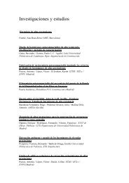
El pres<strong>en</strong>te artículo <strong>de</strong>scribe <strong>la</strong>s características arquitectónicas <strong>de</strong>l edificio situado más al norte <strong>de</strong>l conjunto Cuatro Torres<br />
Business Area (CTBA), <strong>en</strong> Madrid. Tras realizar una introducción con unas reflexiones sobre su concepción se pasa a explicar<br />
los accesos al mismo, así como <strong>la</strong>s p<strong>la</strong>ntas bajo y sobre rasante, indicando el uso <strong>de</strong> <strong>la</strong>s mismas, tanto <strong>en</strong> <strong>la</strong>s <strong>de</strong> uso público como<br />
<strong>en</strong> <strong>la</strong>s técnicas <strong>de</strong>stinadas a los equipos <strong>de</strong> <strong>la</strong>s insta<strong>la</strong>ciones. Finalm<strong>en</strong>te, se muestra el p<strong>la</strong>nteami<strong>en</strong>to <strong>de</strong> <strong>la</strong> fachada <strong>de</strong>l edificio<br />
y <strong>de</strong> <strong>la</strong> climatización <strong>de</strong> los volúm<strong>en</strong>es afectados.<br />
Pa<strong>la</strong>bras c<strong>la</strong>ve: rascacielos, muro climático activo.<br />
ABSTRACT<br />
This article <strong>de</strong>scribes the architectural features of the building located most to the north out of the overall Cuatro Torres<br />
Business Area (CTBA), in Madrid. After an introduction with thoughts on its conception, the accesses to the tower are exp<strong>la</strong>ined<br />
as well as the ground floor and above street level floors, <strong>de</strong>scribing the use to which they are earmarked both with respect to the<br />
public and to the technologies for the instal<strong>la</strong>tions’ equipm<strong>en</strong>t. Finally, the approach tak<strong>en</strong> to the building’s faça<strong>de</strong>s and air conditioning<br />
of the areas involved are <strong>de</strong>scribed.<br />
Key words: Skyscraper, active climate wall.<br />
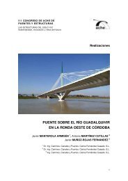
Realizaciones y Proyectos
Realizaciones y Proyectos<br />
J. Bruguera<br />
Figura 1. So<strong>la</strong>r ocupado por <strong>la</strong> Ciudad Deportiva <strong>de</strong>l Real Madrid antes <strong>de</strong> <strong>la</strong> construcción<br />
<strong>de</strong> <strong>la</strong>s torres.<br />
Figure 1 . Site occupied by the Real Madrid Sports Complex before the towers were built .<br />
1. INTRODUCTION<br />
Promoted by the Vil<strong>la</strong>r Mir Group, the<br />
Torre Espacio building occupies a privileged<br />
site in Madrid’s most important<br />
av<strong>en</strong>ue and, therefore, should provi<strong>de</strong><br />
something more than attractive, effici<strong>en</strong>t<br />
office spaces: it should str<strong>en</strong>gth<strong>en</strong><br />
the surroundings in which it is embodied<br />
apart from reviving Madrid’s street<br />
profile, since it will be one of the city’s<br />
most promin<strong>en</strong>t buildings (Figure 1). In<br />
or<strong>de</strong>r to take advantage of this opportunity<br />
whilst at once fulfilling these premises,<br />
we have proposed a unique, sl<strong>en</strong><strong>de</strong>r<br />
building whose geometry provi<strong>de</strong>s a<br />
changing view (Figure 2).<br />
In the words of H<strong>en</strong>ry Cobb, Torre<br />
Espacio owes its peculiar shape to an<br />
impulse: the <strong>de</strong>sire to prove something,<br />
to bring what is inert to life, to make the<br />
immovable mobile. Not cont<strong>en</strong>t to have<br />
our tower erect on the ground, we wanted<br />
it to climb up from the earth like<br />
something growing. Every form of p<strong>la</strong>nt<br />
life, be it a b<strong>la</strong><strong>de</strong> of grass or a robust<br />
tree, changes its structure while growing.<br />
Therefore, from the root to the<br />
trunk, the branch and the leaf, the evolution<br />
of its shape proves it is alive.<br />
Could a skyscraper -its concrete<br />
frame being wrapped in a firm skin of<br />
metal and g<strong>la</strong>ss - be mo<strong>de</strong>lled in such a<br />
way that it were se<strong>en</strong> in another light, as<br />
if having ris<strong>en</strong> from the earth as a real<br />
living being?<br />
We began our experim<strong>en</strong>t <strong>en</strong><strong>de</strong>avouring<br />
to imagine how a high rise building,<br />
with a square p<strong>la</strong>n at its base, could<br />
gradually evolve into a rhombus formed<br />
by two fourth parts of a circle at its<br />
crown. Our aim was to cause a rotational<br />
change that would give life to the tower<br />
by exposing differ<strong>en</strong>t shapes in a peculiar<br />
manner, se<strong>en</strong> from differ<strong>en</strong>t points<br />
(Figure 3). After trying out several sloping,<br />
stepped profiles, we discovered that<br />
the cosine curve was the i<strong>de</strong>al geometrical<br />
mechanism to achieve the evolution<br />
<strong>de</strong>sired in a shape un<strong>de</strong>r construction<br />
(Figure 4). By distributing the points of<br />
intersection betwe<strong>en</strong> the emerging<br />
curved surfaces and the orthogonal compon<strong>en</strong>ts<br />
falling back from the tower’s<br />
successive storeys, the cosine curve facilitates<br />
the building and assembling of the<br />
tower’s outsi<strong>de</strong> wall. But, ev<strong>en</strong> more important,<br />
seeing that its in<strong>de</strong>x of curvature<br />
is not constant but <strong>de</strong>creases as it advances,<br />
the cosine curve gives a palpable<br />
feeling of acceleration <strong>en</strong>ergising the<br />
tower’s shape, giving it life. We believe<br />
we have found the means whereby our<br />
tower disp<strong>la</strong>ys what we wanted.<br />
2. ACCESSES<br />
The tower’s main access is gained via<br />
the building’s East and South faça<strong>de</strong>s<br />
which are linked to the Paseo <strong>de</strong> <strong>la</strong><br />
Castel<strong>la</strong>na (Castel<strong>la</strong>na Av<strong>en</strong>ue) through<br />
the new P<strong>la</strong>za (Square) where the four<br />
Torre Espacio. Proyecto arquitectónico<br />
Torre Espacio. Architectural <strong>de</strong>sign<br />
1. INTRODUCCIÓN<br />
El edificio Torre Espacio, promovido<br />
por el Grupo Vil<strong>la</strong>r Mir, ocupa un emp<strong>la</strong>zami<strong>en</strong>to<br />
privilegiado <strong>en</strong> <strong>la</strong> av<strong>en</strong>ida<br />
más importante <strong>de</strong> Madrid, y <strong>de</strong>be por<br />
lo tanto aportar algo más que espacios<br />
<strong>de</strong> oficina atractivos y efici<strong>en</strong>tes: <strong>de</strong>be<br />
pot<strong>en</strong>ciar el <strong>en</strong>torno <strong>en</strong> el que se incorpora,<br />
a<strong>de</strong>más <strong>de</strong> reavivar el perfil urbano<br />
<strong>de</strong> Madrid, puesto que será uno <strong>de</strong><br />
los edificios más promin<strong>en</strong>tes <strong>de</strong> <strong>la</strong> ciudad<br />
(Figura 1). Para aprovechar esta<br />
oportunidad al tiempo que cumplir con<br />
estas premisas, hemos propuesto un edificio<br />
singu<strong>la</strong>r y esbelto con una geometría<br />
que permita t<strong>en</strong>er una visión cambiante<br />
(Figura 2).<br />
De acuerdo con <strong>la</strong>s pa<strong>la</strong>bras <strong>de</strong> H<strong>en</strong>ry<br />
Cobb, Torre Espacio <strong>de</strong>be su peculiar<br />
forma a un impulso: el <strong>de</strong>seo <strong>de</strong> <strong>de</strong>mostrar<br />
algo, <strong>de</strong> darle vida a lo inerte, <strong>de</strong> hacer<br />
movible lo inamovible. No cont<strong>en</strong>tos<br />
con t<strong>en</strong>er nuestra torre erguida sobre el<br />
suelo, queríamos que asc<strong>en</strong>diera <strong>de</strong>s<strong>de</strong> <strong>la</strong><br />
tierra como algo que crece. Toda forma<br />
<strong>de</strong> vida vegetal, sea una brizna <strong>de</strong> hierba<br />
o un árbol robusto, cambia su estructura<br />
mi<strong>en</strong>tras crece. Por tanto, <strong>de</strong>s<strong>de</strong> <strong>la</strong> raíz<br />
hasta el tronco, <strong>la</strong> rama y <strong>la</strong> hoja, <strong>la</strong> evolución<br />
<strong>de</strong> su forma evi<strong>de</strong>ncia su vida.<br />
¿Podría un rascacielos -su armazón <strong>de</strong><br />
hormigón <strong>en</strong>vuelto <strong>en</strong> una piel firme <strong>de</strong><br />
metal y cristal- estar mo<strong>de</strong><strong>la</strong>do <strong>de</strong> tal<br />
forma que fuera visto <strong>de</strong> otro modo, como<br />
habi<strong>en</strong>do surgido <strong>de</strong> <strong>la</strong> tierra, como<br />
un auténtico ser vivo?<br />
Empezamos nuestro experim<strong>en</strong>to int<strong>en</strong>tando<br />
imaginar cómo un edificio <strong>en</strong><br />
altura, <strong>de</strong> p<strong>la</strong>nta cuadrada <strong>en</strong> su base,<br />
podría evolucionar gradualm<strong>en</strong>te a un<br />
rombo formado por dos cuartas partes<br />
<strong>de</strong> un círculo <strong>en</strong> su corona. Nuestro objetivo<br />
era provocar un cambio rotacional<br />
que diera vida a <strong>la</strong> torre exponi<strong>en</strong>do distintas<br />
formas <strong>de</strong> una manera peculiar,<br />
vistas <strong>de</strong>s<strong>de</strong> distintos puntos (Figura 3).<br />
Después <strong>de</strong> probar varios perfiles inclinados<br />
y escalonados, <strong>de</strong>scubrimos que<br />
<strong>la</strong> curva cos<strong>en</strong>o era el mecanismo geométrico<br />
i<strong>de</strong>al para lograr <strong>la</strong> evolución<br />
<strong>de</strong>seada <strong>en</strong> una forma <strong>en</strong> construcción<br />
(Figura 4). Distribuy<strong>en</strong>do los puntos <strong>de</strong><br />
intersección <strong>en</strong>tre <strong>la</strong>s superficies curvas<br />
emerg<strong>en</strong>tes y los compon<strong>en</strong>tes ortogonales<br />
que retroce<strong>de</strong>n <strong>de</strong> p<strong>la</strong>ntas sucesivas<br />
<strong>de</strong> <strong>la</strong> torre, <strong>la</strong> curva <strong>de</strong>l cos<strong>en</strong>o facilita<br />
<strong>la</strong> fabricación y el <strong>en</strong>samb<strong>la</strong>je <strong>de</strong>l<br />
muro <strong>de</strong> cerrami<strong>en</strong>to <strong>de</strong> <strong>la</strong> torre. Pero<br />
10 Hormigón y Acero • Volum<strong>en</strong> 59, n o 249 • julio-septiembre, 2008 • Madrid (España) • ISSN: 0439-5689
Torre Espacio. Proyecto arquitectónico<br />
Torre Espacio. Architectural <strong>de</strong>sign<br />
Figura 2. El mo<strong>de</strong>lo digital <strong>de</strong>l edificio Torre Espacio <strong>de</strong>s<strong>de</strong> difer<strong>en</strong>tes puntos <strong>de</strong> vista.<br />
Figure 2 – The Torre Espacio building’s digital mo<strong>de</strong>l from differ<strong>en</strong>t points of view.<br />
más importante aun, <strong>de</strong>bido a que su índice<br />
<strong>de</strong> curvatura no es constante sino<br />
que <strong>de</strong>crece mi<strong>en</strong>tras avanza, <strong>la</strong> curva<br />
cos<strong>en</strong>o imparte un s<strong>en</strong>tido palpable <strong>de</strong><br />
aceleración que <strong>en</strong>ergiza <strong>la</strong> forma <strong>de</strong> <strong>la</strong><br />
torre, dándole vida. Creemos que hemos<br />
<strong>en</strong>contrado los medios para que<br />
nuestra torre muestre lo que queríamos.<br />
Figura 3. Variación <strong>de</strong> <strong>la</strong> forma <strong>de</strong> <strong>la</strong>s p<strong>la</strong>ntas con <strong>la</strong> altura.<br />
Figure 3. Variation in the shape of the floors with height .<br />
Hormigón y Acero • Volum<strong>en</strong> 59, n o 249 • julio-septiembre, 2008 • Madrid (España) • ISSN: 0439-5689<br />
J. Bruguera<br />
overall towers are located.<br />
The access therefore offers<br />
a view of the <strong>de</strong>velopm<strong>en</strong>t<br />
with its pond and gar<strong>de</strong>n areas<br />
around the tower (Figures<br />
5 and 6).<br />
Cars and lorries reach<br />
the Building’s car park from<br />
the un<strong>de</strong>rground road running<br />
around the perimeter<br />
as per the schematic<br />
arrangem<strong>en</strong>t <strong>de</strong>fined in the<br />
Partial Developm<strong>en</strong>t P<strong>la</strong>n.<br />
The perimeter road’s level<br />
which is, therefore, that of<br />
the car park’s <strong>en</strong>try and exit,<br />
is approximately -6.9<br />
corresponding to storey -2.<br />
Two accesses are avai<strong>la</strong>ble,<br />
one at the East <strong>en</strong>d of the<br />
ground and the other at its<br />
West <strong>en</strong>d. The service vehicle<br />
<strong>en</strong>try and exit are located<br />
at the West <strong>en</strong>d. Vehicles<br />
are internally distributed<br />
over the 6 un<strong>de</strong>rground car<br />
park floors via two ramps.<br />
The building is <strong>en</strong>tered<br />
through two halls with revolving<br />
doors arranged in<br />
the faça<strong>de</strong>s m<strong>en</strong>tioned or<br />
through a bank of four lifts<br />
coming from the below<br />
street level car park. The<br />
three storey high main hall<br />
is accessed where the two reception areas<br />
are located. The main hall is consi<strong>de</strong>red<br />
as a transition area betwe<strong>en</strong> floors<br />
above ground level and the basem<strong>en</strong>ts,<br />
as being the main access route to the<br />
building’s differ<strong>en</strong>t areas. Two security<br />
control points have therefore be<strong>en</strong> sited<br />
betwe<strong>en</strong> the main <strong>en</strong>trance and the bank<br />
of lifts.<br />
The building’s c<strong>en</strong>tral architectural<br />
core [1] organises both vertical and<br />
horizontal traffic. It inclu<strong>de</strong>s four banks<br />
of lifts servicing the building’s differ<strong>en</strong>t<br />
areas. The first bank is formed by four<br />
lifts that service the six below street level<br />
car parks. The remaining three banks<br />
have six lifts which serve the building’s<br />
office floors divi<strong>de</strong>d into three areas:<br />
Floors 1 to 18, Floors 18 to 33 and<br />
Floors 33 to 52. Apart from the public<br />
lifts, the architectural core houses the<br />
services, technical instal<strong>la</strong>tions galleries<br />
and two service lifts. The lift hall<br />
provi<strong>de</strong>s access to the rear part of the<br />
building which is unique in character<br />
Realizaciones y Proyectos<br />
11
Realizaciones y Proyectos<br />
J. Bruguera<br />
Figura 4. G<strong>en</strong>eración <strong>de</strong> <strong>la</strong> geometría <strong>de</strong>l edificio a partir <strong>de</strong> <strong>la</strong> curva cos<strong>en</strong>o.<br />
Figure 4. G<strong>en</strong>eration of the building’s geometry from the cosine curve.<br />
and for common use. This area of the<br />
building consists of three mezzanines<br />
organised around a three storey high<br />
triangu<strong>la</strong>r atrium, with a lift providing a<br />
panoramic view, a monum<strong>en</strong>tal staircase<br />
and two storey high areas with ter-<br />
Figura 5. Infografía con el acceso peatonal el edificio.<br />
Figure 5. Infography with the building’s pe<strong>de</strong>strian access.<br />
Torre Espacio. Proyecto arquitectónico<br />
Torre Espacio. Architectural <strong>de</strong>sign<br />
2. ACCESOS<br />
El acceso principal a <strong>la</strong> torre se produce<br />
por <strong>la</strong>s fachadas Este y Sur <strong>de</strong>l edificio<br />
que están vincu<strong>la</strong>das con el Paseo<br />
<strong>de</strong> <strong>la</strong> Castel<strong>la</strong>na a través <strong>de</strong> <strong>la</strong> nueva<br />
P<strong>la</strong>za <strong>en</strong> <strong>la</strong> que se ubican <strong>la</strong>s cuatro torres<br />
<strong>de</strong>l conjunto. El recorrido <strong>de</strong> acceso<br />
ofrece, por tanto, una vista <strong>de</strong> <strong>la</strong> urbanización<br />
con sus zonas <strong>de</strong> estanques y<br />
ajardinadas que se <strong>de</strong>sarrol<strong>la</strong>n alre<strong>de</strong>dor<br />
<strong>de</strong> <strong>la</strong> torre (Figuras 5 y 6).<br />
Los coches y los camiones acce<strong>de</strong>n al<br />
parking <strong>de</strong>l edificio <strong>de</strong>s<strong>de</strong> el viario subterráneo<br />
situado perimetralm<strong>en</strong>te a <strong>la</strong>s<br />
parce<strong>la</strong>s según <strong>la</strong> disposición esquemática<br />
<strong>de</strong>finida <strong>en</strong> el P<strong>la</strong>n Parcial. La cota<br />
<strong>de</strong>l viario perimetral, y por tanto <strong>de</strong> <strong>la</strong>s<br />
<strong>en</strong>tradas y salidas <strong>de</strong>l aparcami<strong>en</strong>to, es<br />
aproximadam<strong>en</strong>te -6,9 correspondi<strong>en</strong>do<br />
a <strong>la</strong> p<strong>la</strong>nta -2. Se dispon<strong>en</strong> dos accesos,<br />
uno <strong>en</strong> el límite Este <strong>de</strong>l terr<strong>en</strong>o y otro<br />
<strong>en</strong> el límite Oeste <strong>de</strong>l mismo. La <strong>en</strong>trada<br />
y salida <strong>de</strong> los vehículos <strong>de</strong> servicio<br />
están ubicadas <strong>en</strong> el límite Oeste. La<br />
distribución interna <strong>de</strong> los vehículos <strong>en</strong><br />
<strong>la</strong>s 6 p<strong>la</strong>ntas bajo rasante <strong>de</strong> aparcami<strong>en</strong>to<br />
se lleva a cabo a través <strong>de</strong> dos<br />
rampas.<br />
La <strong>en</strong>trada al edificio se produce a<br />
través <strong>de</strong> dos vestíbulos con puertas giratorias<br />
dispuestas <strong>en</strong> <strong>la</strong>s fachadas indicadas,<br />
o bi<strong>en</strong> a través <strong>de</strong> un núcleo <strong>de</strong><br />
cuatro asc<strong>en</strong>sores que vi<strong>en</strong><strong>en</strong> <strong>de</strong>l aparcami<strong>en</strong>to<br />
bajo rasante. Se acce<strong>de</strong> directam<strong>en</strong>te<br />
al vestíbulo principal <strong>de</strong> triple<br />
altura don<strong>de</strong> se distribuy<strong>en</strong> los dos espacios<br />
<strong>de</strong> recepción. El vestíbulo principal<br />
se consi<strong>de</strong>ra como un espacio <strong>de</strong><br />
transición <strong>en</strong>tre <strong>la</strong>s p<strong>la</strong>ntas sobre rasante<br />
y los sótanos, por ser <strong>la</strong> principal vía<br />
<strong>de</strong> acceso a <strong>la</strong>s difer<strong>en</strong>tes zonas <strong>de</strong>l edificio.<br />
En consecu<strong>en</strong>cia, se han previsto<br />
dos puntos <strong>de</strong> control <strong>de</strong> seguridad situados<br />
<strong>en</strong>tre <strong>la</strong> <strong>en</strong>trada principal y el núcleo<br />
<strong>de</strong> comunicación vertical.<br />
El núcleo c<strong>en</strong>tral [1] arquitectónico<br />
<strong>de</strong>l edificio organiza <strong>la</strong>s circu<strong>la</strong>ciones<br />
tanto verticales como horizontales <strong>de</strong><br />
personas e insta<strong>la</strong>ciones. En él se incluy<strong>en</strong><br />
cuatro baterías <strong>de</strong> asc<strong>en</strong>sores que<br />
dan servicio a <strong>la</strong>s difer<strong>en</strong>tes zonas <strong>de</strong>l<br />
edificio. El primer grupo está formado<br />
por cuatro asc<strong>en</strong>sores que sirv<strong>en</strong> a <strong>la</strong>s<br />
seis p<strong>la</strong>ntas <strong>de</strong>l parking bajo rasante.<br />
Las otras tres baterías restantes son <strong>de</strong><br />
seis asc<strong>en</strong>sores los cuales sirv<strong>en</strong> a todas<br />
<strong>la</strong>s p<strong>la</strong>ntas <strong>de</strong> oficinas <strong>de</strong>l edificio divididas<br />
<strong>en</strong> tres zonas: P<strong>la</strong>ntas 1 a 18,<br />
12 Hormigón y Acero • Volum<strong>en</strong> 59, n o 249 • julio-septiembre, 2008 • Madrid (España) • ISSN: 0439-5689
Torre Espacio. Proyecto arquitectónico<br />
Torre Espacio. Architectural <strong>de</strong>sign<br />
Figura 6. Infografía con el vestíbulo <strong>de</strong> acceso al edificio.<br />
Figure 6. Infography with the building’s access lobby.<br />
P<strong>la</strong>ntas 18 a 33, y P<strong>la</strong>ntas 33 a 52. El<br />
núcleo arquitectónico alberga, a<strong>de</strong>más<br />
<strong>de</strong> los asc<strong>en</strong>sores públicos, los servicios,<br />
<strong>la</strong>s galerías técnicas <strong>de</strong> insta<strong>la</strong>ciones<br />
y dos asc<strong>en</strong>sores <strong>de</strong> servicio. A través<br />
<strong>de</strong> los vestíbulos <strong>de</strong> asc<strong>en</strong>sores se<br />
acce<strong>de</strong> a <strong>la</strong> parte posterior <strong>de</strong>l edificio<br />
que es <strong>de</strong> carácter singu<strong>la</strong>r y uso común.<br />
Este área <strong>de</strong>l edificio consta <strong>de</strong> tres <strong>en</strong>trep<strong>la</strong>ntas<br />
organizadas alre<strong>de</strong>dor <strong>de</strong> un<br />
atrio triangu<strong>la</strong>r <strong>de</strong> triple altura con un<br />
asc<strong>en</strong>sor panorámico, una escalera monum<strong>en</strong>tal<br />
y espacios <strong>de</strong> doble altura,<br />
con usos terciarios y comerciales al servicio<br />
<strong>de</strong>l uso principal <strong>de</strong> oficinas.<br />
3. PLANTAS BAJO RASANTE<br />
Fuera <strong>de</strong>l perímetro que ocupa <strong>la</strong> Torre<br />
sobre rasante, y ll<strong>en</strong>ando todos los límites<br />
<strong>de</strong>l so<strong>la</strong>r, se <strong>de</strong>sarrol<strong>la</strong> el aparcami<strong>en</strong>to<br />
g<strong>en</strong>eral <strong>en</strong> seis p<strong>la</strong>ntas. En <strong>la</strong>s seis<br />
p<strong>la</strong>ntas bajo rasante que ocupan el perímetro<br />
<strong>de</strong>l <strong>la</strong> Torre, se ubican <strong>en</strong> g<strong>en</strong>eral<br />
los espacios que no requier<strong>en</strong> luz natural<br />
como mant<strong>en</strong>imi<strong>en</strong>to <strong>de</strong> insta<strong>la</strong>ciones,<br />
espacios técnicos y <strong>de</strong> insta<strong>la</strong>ciones, y<br />
los espacios <strong>de</strong> uso ocasional vincu<strong>la</strong>dos<br />
al acceso <strong>de</strong>l aparcami<strong>en</strong>to VIP.<br />
Las características básicas <strong>de</strong>l aparcami<strong>en</strong>to<br />
son <strong>la</strong>s sigui<strong>en</strong>tes:<br />
– 1.150 p<strong>la</strong>zas distribuidas <strong>en</strong> 6<br />
P<strong>la</strong>ntas Bajo Rasante.<br />
– Aparcami<strong>en</strong>to restringido para<br />
VIPS con acceso directo a los asc<strong>en</strong>sores.<br />
– Aparcami<strong>en</strong>to para 3 camiones o<br />
10 furgonetas <strong>en</strong> <strong>la</strong> P<strong>la</strong>nta S2.<br />
4. PLANTAS SOBRE RASANTE<br />
En re<strong>la</strong>ción a <strong>la</strong> tipología <strong>de</strong> p<strong>la</strong>nta, el<br />
edificio sobre rasante pue<strong>de</strong> dividirse<br />
<strong>en</strong> cuatro tipos difer<strong>en</strong>ciados (Figura 7):<br />
– Tres p<strong>la</strong>ntas <strong>de</strong> accesos con usos <strong>de</strong><br />
Cafetería, Gimnasio, Restaurante.<br />
– Cuar<strong>en</strong>ta y tres p<strong>la</strong>ntas tipo <strong>de</strong> oficina.<br />
– Dos p<strong>la</strong>ntas <strong>de</strong> uso común (Sky lobbies<br />
<strong>en</strong> <strong>la</strong>s P<strong>la</strong>ntas 18 y 23).<br />
– Dos P<strong>la</strong>ntas <strong>de</strong> Dirección Corporativa.<br />
– Tres p<strong>la</strong>ntas Técnicas (P<strong>la</strong>ntas M1,<br />
M2 y M3).<br />
4.1. P<strong>la</strong>ntas tipo <strong>de</strong> oficinas<br />
Estas p<strong>la</strong>ntas están diseñadas para<br />
permitir <strong>la</strong> máxima flexibilidad para difer<strong>en</strong>tes<br />
tipologías <strong>de</strong> oficinas. El módulo<br />
tipo tanto <strong>de</strong> fachada como <strong>de</strong> falso<br />
techo es <strong>de</strong> 1,20m, permiti<strong>en</strong>do el<br />
Hormigón y Acero • Volum<strong>en</strong> 59, n o 249 • julio-septiembre, 2008 • Madrid (España) • ISSN: 0439-5689<br />
J. Bruguera<br />
tiary and commercial uses in the service<br />
of the main office use.<br />
3. FLOORS BELOW GROUND<br />
LEVEL<br />
The six floor g<strong>en</strong>eral car park is outsi<strong>de</strong><br />
the perimeter of the Tower occupies<br />
above ground level and fills all the<br />
plot’s limits. Areas not calling for natural<br />
lighting are located in g<strong>en</strong>eral on<br />
the six floors below ground level occupying<br />
the Tower’s perimeter, such as instal<strong>la</strong>tion<br />
maint<strong>en</strong>ance, technical and<br />
instal<strong>la</strong>tion areas and areas used occasionally,<br />
connected to the VIP car park<br />
access.<br />
The car park’s basic features are:<br />
– 1,150 car spaces distributed over<br />
the 6 below Ground Level Storeys.<br />
– Car park restricted to VIPs with direct<br />
lift access.<br />
– Parking lot for 3 lorries or 10 vans<br />
on Storey S2.<br />
4. ABOVE GROUND LEVEL<br />
FLOORS<br />
The building above ground level can<br />
be divi<strong>de</strong>d into four differ<strong>en</strong>t types of<br />
floor (Figure 7):<br />
– Three floors for Snack/Coffee Bar,<br />
Gymnasium and Restaurant uses.<br />
– Forty three office type floors.<br />
– Two floors for common use (Sky<br />
lobbies on Floors 18 and 23).<br />
– Two Corporative Managem<strong>en</strong>t<br />
Floors.<br />
– Three Technical Floors (Floors<br />
M1, M2 and M3).<br />
4.1. Office type floors<br />
These floors are <strong>de</strong>signed to allow<br />
maximum flexibility to the differ<strong>en</strong>t<br />
types of office. The standard faça<strong>de</strong> and<br />
false ceiling module is 1.20m, allowing<br />
the floor to be used both as for op<strong>en</strong><br />
Realizaciones y Proyectos<br />
13
Realizaciones y Proyectos<br />
J. Bruguera<br />
Figura 7. Alzado seccionado <strong>de</strong> <strong>la</strong> torre con <strong>la</strong>s difer<strong>en</strong>tes zonas <strong>de</strong>l edificio.<br />
Figure 7. Cross sectioned elevation of the tower with the building’s differ<strong>en</strong>t areas.<br />
Torre Espacio. Proyecto arquitectónico<br />
Torre Espacio. Architectural <strong>de</strong>sign<br />
14 Hormigón y Acero • Volum<strong>en</strong> 59, n o 249 • julio-septiembre, 2008 • Madrid (España) • ISSN: 0439-5689
Torre Espacio. Proyecto arquitectónico<br />
Torre Espacio. Architectural <strong>de</strong>sign<br />
uso tanto como p<strong>la</strong>nta abierta para oficinas<br />
tipo paisaje, como el uso <strong>en</strong> <strong>de</strong>spachos<br />
compartim<strong>en</strong>tados con difer<strong>en</strong>tes<br />
configuraciones. Todas <strong>la</strong>s oficinas<br />
ti<strong>en</strong><strong>en</strong> vistas al exterior y dispon<strong>en</strong> <strong>de</strong><br />
luz natural, y dado que <strong>la</strong> fachada es <strong>de</strong><br />
doble piel v<strong>en</strong>ti<strong>la</strong>da, permite maximizar<br />
el uso <strong>de</strong> luz natural y <strong>la</strong>s ganancias térmicas.<br />
A estas p<strong>la</strong>ntas se acce<strong>de</strong> a través<br />
<strong>de</strong>l vestíbulo <strong>de</strong> asc<strong>en</strong>sores correspondi<strong>en</strong>te.<br />
Cada p<strong>la</strong>nta <strong>de</strong> oficinas está dividida<br />
<strong>en</strong> dos sectores <strong>de</strong> inc<strong>en</strong>dio in<strong>de</strong>p<strong>en</strong>di<strong>en</strong>tes.<br />
Las características principales <strong>de</strong> estas<br />
p<strong>la</strong>ntas son <strong>la</strong>s sigui<strong>en</strong>tes (Figura 8):<br />
– 43 P<strong>la</strong>ntas <strong>de</strong> oficinas <strong>de</strong> alquiler<br />
<strong>de</strong> primera calidad (C<strong>la</strong>ss A International<br />
Standard).<br />
– Tamaño mínimo <strong>de</strong> alquiler 450 m 2<br />
o media p<strong>la</strong>nta.<br />
– Altura libre suelo-falso techo<br />
2,85 m.<br />
– Módulo <strong>de</strong> p<strong>la</strong>nning <strong>de</strong> oficinas<br />
1,20 m.<br />
4.2. P<strong>la</strong>ntas <strong>de</strong> uso común (Sky<br />
lobbies <strong>en</strong> <strong>la</strong>s P<strong>la</strong>ntas 18 y 33)<br />
Las p<strong>la</strong>ntas 18 y 33 <strong>de</strong>l edificio correspon<strong>de</strong>n<br />
al cambio <strong>de</strong> baterías <strong>de</strong> asc<strong>en</strong>sores<br />
<strong>de</strong> zona baja a zona media, y<br />
<strong>de</strong> zona media a zona <strong>alta</strong> respectiva-<br />
Figura 8. P<strong>la</strong>ntas tipo <strong>de</strong> oficinas <strong>en</strong> <strong>la</strong>s difer<strong>en</strong>tes zonas <strong>de</strong>l edificio.<br />
Figure 8. Typical office floors in differ<strong>en</strong>t areas of the building.<br />
Figura 9. Infografía con una <strong>de</strong> <strong>la</strong>s zonas <strong>de</strong> “sky lobby”.<br />
Figure 9. Infography with one of the sky lobby areas.<br />
m<strong>en</strong>te. El cambio <strong>de</strong> asc<strong>en</strong>sores <strong>en</strong> estas<br />
p<strong>la</strong>ntas se produce a través <strong>de</strong> dos atrios<br />
<strong>de</strong> doble altura, los cuales aparte <strong>de</strong> t<strong>en</strong>er<br />
<strong>la</strong> función <strong>de</strong> cambio <strong>de</strong> asc<strong>en</strong>sores,<br />
ti<strong>en</strong><strong>en</strong> un uso para <strong>de</strong>scanso <strong>de</strong> los usuarios<br />
<strong>de</strong>l edificio. En <strong>la</strong> p<strong>la</strong>nta 18, aparte<br />
<strong>de</strong>l atrio, <strong>la</strong> mitad <strong>de</strong> <strong>la</strong> p<strong>la</strong>nta está <strong>de</strong>stinada<br />
a sa<strong>la</strong>s <strong>de</strong> reuniones subdividibles<br />
para difer<strong>en</strong>tes tamaños <strong>de</strong> grupos<br />
(Figura 9).<br />
Hormigón y Acero • Volum<strong>en</strong> 59, n o 249 • julio-septiembre, 2008 • Madrid (España) • ISSN: 0439-5689<br />
J. Bruguera<br />
p<strong>la</strong>n offices and for offices compartm<strong>en</strong>ted<br />
off with differ<strong>en</strong>t configurations.<br />
All offices have an outsi<strong>de</strong> view and<br />
natural light, and since the faça<strong>de</strong> is<br />
double v<strong>en</strong>ti<strong>la</strong>ted skin, it allows the use<br />
of natural light and thermal gain to be<br />
maximised. Access is gained to these<br />
floors through the pertin<strong>en</strong>t lift hall.<br />
Each office floor is divi<strong>de</strong>d into two<br />
separate fire sectors.<br />
Realizaciones y Proyectos<br />
15
Realizaciones y Proyectos<br />
J. Bruguera<br />
Figura 10. Infografía <strong>de</strong>l muro-cortina.<br />
Figure 10. Courtain-wall infography.<br />
The main features of these floors are<br />
(Figure 8):<br />
– 43 top quality, r<strong>en</strong>ted office floors<br />
(C<strong>la</strong>ss A International Standard).<br />
– Minimum r<strong>en</strong>ted area 450 m 2 or<br />
half a floor.<br />
– 2.85 m clear floor/false ceiling<br />
height.<br />
– 1.20 m office p<strong>la</strong>nning module.<br />
4.2. Common use floors (Sky lobbies<br />
on Floors 18 and 33)<br />
The building’s floors 18 and 33 are<br />
where the banks of lifts change from the<br />
lower area to the mid area and from the<br />
mid area to the upper area respectively.<br />
Two atriums of a double height facilitate<br />
the change of lifts on these floors.<br />
Apart from having a change of lift function,<br />
these atriums have a function as a<br />
rest area for the building’s users. Apart<br />
from the atrium, half of floor 18 is earmarked<br />
to sub-divisible meeting rooms<br />
for differ<strong>en</strong>t group sizes (Figure 9).<br />
4.3. Executive Floors (Floors 51<br />
and 52)<br />
To be occupied by the Vil<strong>la</strong>r Mir<br />
group’s executives, these are two floors<br />
with two storey high areas. The main<br />
access is gained from floor 51 through<br />
the bank of lifts whilst interior movem<strong>en</strong>t<br />
is facilitated by two two-storey<br />
high atriums. The singu<strong>la</strong>r managem<strong>en</strong>t<br />
area is organised around these areas,<br />
<strong>en</strong>abling a panoramic view of the whole<br />
city to be <strong>en</strong>joyed.<br />
The whole approximately<br />
2,000 m 2 area inclu<strong>de</strong>s,<br />
amongst others, the following<br />
uses: halls, offices,<br />
waiting rooms, meeting<br />
rooms, Confer<strong>en</strong>ce room,<br />
Executives’ dining room,<br />
pantry and library.<br />
4.4. Technical Floors<br />
(Floors M1, M2 and M3)<br />
Torre Espacio has three<br />
Technical Floors [2] above<br />
ground level, which service<br />
differ<strong>en</strong>t sections of the<br />
building. The <strong>la</strong>st instal<strong>la</strong>tions<br />
floor (M3) services<br />
the tower’s top section and the items of<br />
machinery and op<strong>en</strong> air sports uses<br />
(swimming pool and paddle track), protected<br />
by an apron in a prolongation of<br />
the building’s faça<strong>de</strong> in or<strong>de</strong>r to reduce<br />
its visual impact in accordance with<br />
Regu<strong>la</strong>tions. Thus the building’s overall<br />
height of 227.25 m is reached, to which<br />
must be ad<strong>de</strong>d communications ant<strong>en</strong>nas,<br />
lightning conductors and other<br />
items required up to a height less than<br />
250 m.<br />
5. BUILDING’S FAÇADE<br />
The concept of the Torre Espacio’s<br />
faça<strong>de</strong> is a double skin with perforated<br />
horizontal s<strong>la</strong>ts allowing natural light<br />
to pass through, privacy of interior areas<br />
and transpar<strong>en</strong>cy of the faça<strong>de</strong>. Its<br />
<strong>de</strong>sign is based on making an Active<br />
Climate Wall allowing radiation <strong>en</strong>ergy<br />
to be used to advantage and <strong>en</strong>ergy to<br />
be saved. This active climate wall consists<br />
in a double g<strong>la</strong>zed curtain wall<br />
with the concept of an active faça<strong>de</strong>.<br />
The interior return air circu<strong>la</strong>tes<br />
through the space betwe<strong>en</strong> the outsi<strong>de</strong><br />
wall and the insi<strong>de</strong> g<strong>la</strong>zed panel, with<br />
the air th<strong>en</strong> returning to the forced v<strong>en</strong>ti<strong>la</strong>tion<br />
system (Figure 10).<br />
The building’s insi<strong>de</strong> air freely circu<strong>la</strong>tes<br />
through the insi<strong>de</strong> of the double<br />
wall cavity, <strong>en</strong>tering through filter<br />
op<strong>en</strong>ings at floor level and exiting<br />
through the v<strong>en</strong>ti<strong>la</strong>tion ducts at the top.<br />
The curtain wall thus offers great modu<strong>la</strong>r<br />
flexibility in controlling the outsi<strong>de</strong><br />
ambi<strong>en</strong>ce (natural light, temperature,<br />
humidity, wind and noise), to the b<strong>en</strong>efit<br />
of the building’s occupants whilst at<br />
Torre Espacio. Proyecto arquitectónico<br />
Torre Espacio. Architectural <strong>de</strong>sign<br />
4.3. P<strong>la</strong>ntas <strong>de</strong> Dirección (P<strong>la</strong>ntas 51<br />
y 52)<br />
Éstas, que serán ocupadas por <strong>la</strong><br />
Dirección G<strong>en</strong>eral <strong>de</strong>l Grupo Vil<strong>la</strong>r Mir,<br />
se <strong>de</strong>sarrol<strong>la</strong>n <strong>en</strong> dos p<strong>la</strong>ntas con espacios<br />
<strong>de</strong> doble altura. El acceso principal<br />
es <strong>de</strong>s<strong>de</strong> <strong>la</strong> p<strong>la</strong>nta 51 a través <strong>de</strong>l núcleo<br />
<strong>de</strong> asc<strong>en</strong>sores, mi<strong>en</strong>tras que <strong>la</strong> circu<strong>la</strong>ción<br />
interior se facilita mediante dos<br />
atrios <strong>de</strong> doble altura. Alre<strong>de</strong>dor <strong>de</strong> éstos<br />
se organizan los espacios singu<strong>la</strong>res<br />
<strong>de</strong> <strong>la</strong> zona <strong>de</strong> dirección, disfrutándose<br />
<strong>de</strong> este modo <strong>de</strong> vistas panorámicas <strong>de</strong><br />
toda <strong>la</strong> ciudad.<br />
En <strong>la</strong> superficie total construida <strong>de</strong><br />
aproximadam<strong>en</strong>te 2.000 m 2 se incluy<strong>en</strong>,<br />
<strong>en</strong>tre otros, los sigui<strong>en</strong>tes usos: vestíbulos,<br />
<strong>de</strong>spachos, sa<strong>la</strong>s <strong>de</strong> espera, sa<strong>la</strong>s <strong>de</strong><br />
reuniones, sa<strong>la</strong> <strong>de</strong> Confer<strong>en</strong>cias, comedor<br />
<strong>de</strong> Directivos, office y biblioteca.<br />
4.4. P<strong>la</strong>ntas Técnicas (P<strong>la</strong>ntas M1,<br />
M2 y M3)<br />
Torre Espacio cu<strong>en</strong>ta con tres P<strong>la</strong>ntas<br />
Técnicas [2] sobre rasante, que dan servicio<br />
a difer<strong>en</strong>tes secciones <strong>de</strong>l edificio.<br />
La última p<strong>la</strong>nta <strong>de</strong> insta<strong>la</strong>ciones (M3)<br />
da servicio a <strong>la</strong> sección superior <strong>de</strong> <strong>la</strong><br />
torre y los elem<strong>en</strong>tos <strong>de</strong> maquinaria y<br />
usos <strong>de</strong>portivos al aire libre (piscina y<br />
pista <strong>de</strong> paddle), protegidos por un peto<br />
<strong>en</strong> prolongación <strong>de</strong> <strong>la</strong> fachada <strong>de</strong>l edificio<br />
para reducir su impacto visual <strong>de</strong><br />
acuerdo con <strong>la</strong> Normativa. De este modo<br />
se alcanza <strong>la</strong> altura total <strong>de</strong>l edificio<br />
<strong>de</strong> 227,25 m, a <strong>la</strong> que habrá que sumar<br />
<strong>la</strong>s ant<strong>en</strong>as <strong>de</strong> comunicaciones, pararrayos<br />
y <strong>de</strong>más elem<strong>en</strong>tos precisos hasta<br />
una altura inferior a los 250 m.<br />
5. FACHADA DEL EDIFICIO<br />
El concepto <strong>de</strong> fachada <strong>de</strong> Torre<br />
Espacio, es una doble piel con <strong>la</strong>mas perforadas<br />
horizontales que permit<strong>en</strong> el paso<br />
<strong>de</strong> luz natural, <strong>la</strong> privacidad <strong>de</strong> los espacios<br />
interiores y <strong>la</strong> transpar<strong>en</strong>cia <strong>de</strong> <strong>la</strong><br />
fachada. El proyecto <strong>de</strong> <strong>la</strong> misma se basa<br />
<strong>en</strong> <strong>la</strong> realización <strong>de</strong> un Muro Climático<br />
Activo que permite el aprovechami<strong>en</strong>to y<br />
el ahorro <strong>de</strong> <strong>la</strong> <strong>en</strong>ergía <strong>de</strong> radiación. Este<br />
muro climático activo, consiste <strong>en</strong> un<br />
muro-cortina <strong>de</strong> doble acrista<strong>la</strong>mi<strong>en</strong>to<br />
diseñado con el concepto <strong>de</strong> fachada activa.<br />
El aire interior <strong>de</strong> retorno circu<strong>la</strong><br />
por el espacio <strong>en</strong>tre el cerrami<strong>en</strong>to exterior<br />
y el panel acrista<strong>la</strong>do interior, retornando<br />
posteriorm<strong>en</strong>te el aire al sistema<br />
<strong>de</strong> v<strong>en</strong>ti<strong>la</strong>ción forzada (Figura 10).<br />
16 Hormigón y Acero • Volum<strong>en</strong> 59, n o 249 • julio-septiembre, 2008 • Madrid (España) • ISSN: 0439-5689
Torre Espacio. Proyecto arquitectónico<br />
Torre Espacio. Architectural <strong>de</strong>sign<br />
Figura 11. Esquema <strong>de</strong> funcionami<strong>en</strong>to <strong>de</strong> <strong>la</strong> climatización.<br />
Figure 11. Air conditioning operating diagram.<br />
El aire interior <strong>de</strong>l edificio circu<strong>la</strong> librem<strong>en</strong>te<br />
por el interior <strong>de</strong> <strong>la</strong> cavidad<br />
<strong>de</strong>l doble muro, <strong>en</strong>trando por aberturas<br />
filtrantes a nivel <strong>de</strong>l suelo y sali<strong>en</strong>do a<br />
través <strong>de</strong> los conductos <strong>de</strong> v<strong>en</strong>ti<strong>la</strong>ción<br />
<strong>en</strong> <strong>la</strong> parte superior. De esta forma el<br />
muro-cortina ofrece <strong>gran</strong> flexibilidad<br />
modu<strong>la</strong>r <strong>en</strong> el control <strong>de</strong>l ambi<strong>en</strong>te exterior<br />
(luz natural, temperatura, humedad,<br />
vi<strong>en</strong>to y ruidos), para b<strong>en</strong>eficio <strong>de</strong><br />
los ocupantes <strong>de</strong>l edificio al mismo<br />
tiempo que garantiza <strong>la</strong> conservación <strong>de</strong><br />
<strong>en</strong>ergía. Este control se lleva a cabo a<br />
través <strong>de</strong> <strong>la</strong>s <strong>la</strong>mas horizontales perforadas<br />
que pue<strong>de</strong>n ser levantadas, bajadas<br />
o inclinadas por el sistema <strong>de</strong> control<br />
computerizado <strong>de</strong>l edificio.<br />
6. CLIMATIZACIÓN<br />
El sistema <strong>de</strong> climatización <strong>de</strong>l edificio<br />
es <strong>de</strong> tipo “hibrido” aire/agua con<br />
aire exterior <strong>de</strong> v<strong>en</strong>ti<strong>la</strong>ción, y paneles<br />
fríos <strong>de</strong> techo. El aire que se impulsa al<br />
ambi<strong>en</strong>te es <strong>de</strong> 2,5 R/H <strong>de</strong>l volum<strong>en</strong> <strong>de</strong><br />
los locales con 100% <strong>de</strong> aire exterior.<br />
Este aire primario es pretratado <strong>en</strong> <strong>la</strong><br />
UTA C<strong>en</strong>tral y se <strong>en</strong>carga a<strong>de</strong>más <strong>de</strong><br />
combatir <strong>la</strong> carga <strong>la</strong>t<strong>en</strong>te, contro<strong>la</strong>r el<br />
grado <strong>de</strong> humedad re<strong>la</strong>tiva ambi<strong>en</strong>te y<br />
una parte <strong>de</strong> <strong>la</strong> carga s<strong>en</strong>sible, ya que se<br />
impulsa a 18 ºC aproximadam<strong>en</strong>te, excepto<br />
durante <strong>la</strong> puesta <strong>en</strong> marcha invernal<br />
(Figura 11).<br />
La carga s<strong>en</strong>sible <strong>de</strong> verano (radiación<br />
so<strong>la</strong>r, transmisión, personas, equipos,<br />
iluminación, etc.) se combate con<br />
los paneles fríos <strong>de</strong> techos por los que<br />
circu<strong>la</strong> agua <strong>en</strong>friada a 15/16 ºC.<br />
La eficacia <strong>de</strong> <strong>la</strong> v<strong>en</strong>ti<strong>la</strong>ción <strong>de</strong> suelo<br />
a techo y <strong>la</strong> eliminación <strong>de</strong> contaminantes<br />
es excel<strong>en</strong>te y <strong>la</strong> flexibilidad <strong>de</strong> distribución<br />
<strong>de</strong> aire <strong>de</strong> v<strong>en</strong>ti<strong>la</strong>ción y extracción<br />
por techo máxima, <strong>de</strong> cara a <strong>la</strong>s<br />
distribuciones internas <strong>de</strong> espacios, personas<br />
y usos, que se supone será cambiante<br />
<strong>en</strong> el tiempo e incluso in<strong>de</strong>finida<br />
<strong>en</strong> <strong>la</strong> fase <strong>de</strong> diseño y montaje.<br />
REFERENCIAS<br />
BIBLIOGRÁFICAS<br />
[1] Martínez Calzón, J. y Gómez<br />
Navarro, M., “Torre Espacio. La estructura<br />
<strong>de</strong>l edificio”, Hormigón y Acero, nº<br />
249, 3º T 2008.<br />
[2] “Torre Espacio alcanza su cúspi<strong>de</strong>”,<br />
El Insta<strong>la</strong>dor, nº 440, Abril 2007.<br />
Hormigón y Acero • Volum<strong>en</strong> 59, n o 249 • julio-septiembre, 2008 • Madrid (España) • ISSN: 0439-5689<br />
J. Bruguera<br />
once guaranteeing <strong>en</strong>ergy conservation.<br />
This control is carried out through horizontal<br />
perforated s<strong>la</strong>ts that can be<br />
raised, lowered or sloped by the building’s<br />
computerised control system.<br />
6. AIR CONDITIONING<br />
The building’s air conditioning system<br />
is the “hybrid” air/water type with<br />
outsi<strong>de</strong> v<strong>en</strong>ti<strong>la</strong>tion air and cold ceiling<br />
panels. The air blown out to the atmosphere<br />
is 2.5 R/H of the volume of the<br />
premises with 100% outsi<strong>de</strong> air. This<br />
primary air is pre-treated in the C<strong>en</strong>tral<br />
UTA and also combats the <strong>la</strong>t<strong>en</strong>t load,<br />
controls the re<strong>la</strong>tive ambi<strong>en</strong>t <strong>de</strong>gree of<br />
humidity and a part of the s<strong>en</strong>sitive<br />
load, since it is impelled at approximately<br />
18 ºC, except during winter<br />
start-up (Figure 11).<br />
The s<strong>en</strong>sitive summer load (so<strong>la</strong>r radiation,<br />
transmission, people, equipm<strong>en</strong>t,<br />
lighting, etc.) is combated with<br />
the cold ceiling panels through which<br />
water cooled to 15/16ºC circu<strong>la</strong>tes.<br />
Floor to ceiling v<strong>en</strong>ti<strong>la</strong>tion effici<strong>en</strong>cy<br />
and the removal of pollutants is excell<strong>en</strong>t<br />
and the ceiling air v<strong>en</strong>ti<strong>la</strong>tion and<br />
extraction a maximum, with a view to<br />
the <strong>la</strong>yout of internal spaces, persons<br />
and uses, which it is assumed will be<br />
changing in time and ev<strong>en</strong> un<strong>de</strong>fined in<br />
the <strong>de</strong>sign and erection phase.<br />
REFERENCES<br />
[1] Martínez Calzón, J. y Gómez<br />
Navarro, M., “Torre Espacio. Building<br />
structure”, Hormigón y Acero, nº 249,<br />
3º T 2008.<br />
[2] “Torre Espacio alcanza su cúspi<strong>de</strong>”,<br />
El Insta<strong>la</strong>dor, nº 440, Abril 2007.<br />
Realizaciones y Proyectos<br />
17
Recibido / Received: 11/12/2007<br />
Aceptado / Accepted: 13/02/2008<br />
Torre Espacio. La estructura <strong>de</strong>l edificio<br />
Torre Espacio. Building structure<br />
(1) Dr. Ing<strong>en</strong>iero <strong>de</strong> Caminos, MC-2, Estudio <strong>de</strong> Ing<strong>en</strong>iería<br />
(2) Dr. Ing<strong>en</strong>iero <strong>de</strong> Caminos, MC-2, Estudio <strong>de</strong> Ing<strong>en</strong>iería<br />
Persona <strong>de</strong> contacto / Corresponding author: miguel.gomez@mc2.es<br />
Julio Martínez Calzón (1) y Miguel Gómez Navarro (2)<br />
RESUMEN<br />
Hormigón y Acero<br />
Vol. 59, nº 249, págs. 19-43<br />
julio-septiembre, 2008<br />
ISSN: 0439-5689<br />
El edificio Torre Espacio, con 223 m <strong>de</strong> altura sobre rasante, ha sido proyectado combinando soportes <strong>de</strong> hormigón armado y<br />
losas macizas <strong>de</strong>l mismo material. Este p<strong>la</strong>nteami<strong>en</strong>to estructural, condicionado parcialm<strong>en</strong>te por <strong>la</strong>s prefer<strong>en</strong>cias <strong>de</strong> <strong>la</strong> empresa<br />
promotora <strong>de</strong>l edificio, permite adaptarse con facilidad a los condicionantes <strong>de</strong>terminados por <strong>la</strong> variabilidad <strong>en</strong> p<strong>la</strong>nta <strong>de</strong>l<br />
edificio, habiéndose diseñado una estructura flexible que se ha podido ejecutar mant<strong>en</strong>i<strong>en</strong>do un ritmo <strong>de</strong> <strong>en</strong>tre tres y cuatro p<strong>la</strong>ntas<br />
m<strong>en</strong>suales. El diseño <strong>de</strong> <strong>la</strong> estructura cu<strong>en</strong>ta con <strong>la</strong> co<strong>la</strong>boración <strong>de</strong> su carácter monolítico para aum<strong>en</strong>tar su rigi<strong>de</strong>z horizontal<br />
al po<strong>de</strong>rse contar con <strong>la</strong> co<strong>la</strong>boración <strong>de</strong> los soportes conectados mediante los forjados a los núcleos. En algunos elem<strong>en</strong>tos<br />
singu<strong>la</strong>res (losa <strong>de</strong> cim<strong>en</strong>tación, vigas carga<strong>de</strong>ro, cinturón <strong>de</strong> rigi<strong>de</strong>z, soportes especiales) se han utilizado elem<strong>en</strong>tos metálicos,<br />
mixtos o <strong>de</strong> hormigón pret<strong>en</strong>sado. Las vigas carga<strong>de</strong>ro <strong>de</strong> 27.8 m <strong>de</strong> luz resuelv<strong>en</strong> <strong>la</strong> eliminación <strong>de</strong> soportes <strong>en</strong> <strong>la</strong>s zonas <strong>de</strong> accesos<br />
al edificio, mi<strong>en</strong>tras que el cinturón <strong>de</strong> rigi<strong>de</strong>z que conecta el núcleo con los soportes, ha precisado <strong>de</strong>l bombeo <strong>de</strong> hormigón<br />
HA-80 a una altura <strong>de</strong> 130 m sobre <strong>la</strong> rasante. La co<strong>la</strong>boración durante <strong>la</strong> fase <strong>de</strong> redacción <strong>de</strong>l proyecto <strong>de</strong> los equipos <strong>en</strong>cargados<br />
<strong>de</strong> <strong>la</strong> ejecución <strong>de</strong> <strong>la</strong> obra, ha permitido t<strong>en</strong>er <strong>en</strong> cu<strong>en</strong>ta <strong>de</strong> una manera muy ajustada los importantes condicionantes<br />
constructivos asociados a una obra <strong>de</strong> esta <strong>en</strong>vergadura.<br />
Pa<strong>la</strong>bras c<strong>la</strong>ve: Edificación <strong>de</strong> altura, hormigón armado, hormigón <strong>de</strong> <strong>alta</strong> <strong>resist<strong>en</strong>cia</strong>, efectos aerodinámicos, estabilidad fr<strong>en</strong>te<br />
al fuego, cim<strong>en</strong>taciones especiales, cinturón <strong>de</strong> rigi<strong>de</strong>z<br />
ABSTRACT<br />
223 m high above ground level, the Torre Espacio was <strong>de</strong>signed by combining reinforced concrete supports and solid s<strong>la</strong>bs of<br />
the same material. Partially <strong>de</strong>termined by the prefer<strong>en</strong>ces of the building’s promoter company, this structural approach allows<br />
it to be easily adapted to the conditioning factors <strong>de</strong>termined by the building’s p<strong>la</strong>n variability. A flexible structure was <strong>de</strong>signed<br />
which could be built at a steady rate of betwe<strong>en</strong> three and four floors a month. The structure’s <strong>de</strong>sign relies on the cooperation<br />
of its monolithic nature to increase its horizontal stiffness since the supports connected by the floor s<strong>la</strong>bs to the cores fully cooperated<br />
to such <strong>en</strong>d. Steel, composite or prestressed concrete elem<strong>en</strong>ts were used in some singu<strong>la</strong>r elem<strong>en</strong>ts (foundation s<strong>la</strong>b,<br />
load bearing beams, outriggers, special columns). The 27.8 m span load bearing beams solve the problem of the elimination of<br />
columns in areas providing access to the building, whilst the outrigger connecting the core to the supports required HA-80 concrete<br />
pumping in to a height of 130 m above ground level. Cooperation from the teams in charge of executing the work during<br />
the <strong>de</strong>sign drafting stage <strong>en</strong>abled the important construction conditioning factors associated to a project of this size to be tak<strong>en</strong><br />
into account in a very accurate fashion.<br />
Keywords: High rise building, reinforced concrete, high str<strong>en</strong>gth concrete, aerodynamic effects, fire stability, special foundations,<br />
outrigger<br />
Realizaciones y Proyectos
Realizaciones y Proyectos<br />
J. Martínez y M. Gómez<br />
Figura 1. Vista g<strong>en</strong>eral <strong>de</strong>l mo<strong>de</strong>lo digital <strong>de</strong>l edificio<br />
Torre Espacio<br />
.Figure 1. G<strong>en</strong>eral view of the Torre Espacio building’s<br />
digital mo<strong>de</strong>l<br />
1. GENERAL<br />
The Torre Espacio building consists in<br />
a <strong>la</strong>rge, 56 floor tower, 223 m above<br />
ground level, built in Madrid in the ext<strong>en</strong>sion<br />
to the Paseo <strong>de</strong> <strong>la</strong> Castel<strong>la</strong>na<br />
(Castel<strong>la</strong>na Av<strong>en</strong>ue) following the<br />
Architectural Design as drawn up by the<br />
PEI, COBB, FREED & PARTNERS team<br />
of New York [1] and promoted by the<br />
Torre Espacio Real Estate Firm of the<br />
Espacio Real Estate Group (Figure 1).<br />
The winner of an international competition<br />
called for by the promoter<br />
group, this Architectural Design initially<br />
<strong>de</strong>fined a re<strong>la</strong>tively precise, formal,<br />
architectural solution that inclu<strong>de</strong>d a<br />
suffici<strong>en</strong>tly clear structural arrangem<strong>en</strong>t<br />
to be able to <strong>la</strong>y down functional<br />
and str<strong>en</strong>gth inter-action criteria, with<br />
a certain amount of accuracy, that<br />
would allow a stricter structural approach<br />
to comm<strong>en</strong>ce that would not set<br />
the building’s architectural proposals<br />
against its functional ones.<br />
Furthermore, the building’s<br />
owner and promoter<br />
company (Vil<strong>la</strong>r Mir Group),<br />
which has construction and<br />
auxiliary firms amongst its<br />
members able to un<strong>de</strong>rtake<br />
the building of the structure<br />
and other parts of the Tower,<br />
<strong>la</strong>id down starting conditions<br />
which, whilst not being absolute,<br />
<strong>de</strong>termined a number<br />
of <strong>de</strong>cisions influ<strong>en</strong>cing the<br />
structural <strong>de</strong>sign’s <strong>de</strong>velopm<strong>en</strong>t<br />
and its construction<br />
process. These conditioning<br />
factors were basically as follows:<br />
– Use of reinforced concrete<br />
in its differ<strong>en</strong>t options<br />
as basic structural material:<br />
high str<strong>en</strong>gth or normal, <strong>de</strong>p<strong>en</strong>ding<br />
on the requirem<strong>en</strong>ts<br />
of each elem<strong>en</strong>t in the overall.<br />
This line is framed within<br />
a now consolidated world<br />
tr<strong>en</strong>d in using concrete structures<br />
for high rise buildings<br />
as a competitive alternative<br />
to more c<strong>la</strong>ssic solutions in<br />
steel structures [2]<br />
– A construction process<br />
with the maximum effici<strong>en</strong>cy<br />
and speed, with prefer<strong>en</strong>ce<br />
over slower, more traditional<br />
systems typical of normal<br />
building.<br />
A number of aspects of a varying kind<br />
re<strong>la</strong>ting to highly diverse chance categories<br />
may be m<strong>en</strong>tioned together with<br />
these conditioning factors:<br />
– Work site located and situated in a<br />
highly influ<strong>en</strong>tial, well known area of<br />
the city;<br />
– Quality and image of the building<br />
in re<strong>la</strong>tion to the city and the prestige of<br />
its promoters;<br />
– Complex re<strong>la</strong>tions with the surroundings,<br />
with respect to connections<br />
and processes involved in its building in<br />
the urban ambi<strong>en</strong>ce and in the actual<br />
linking of the tower with the car park<br />
<strong>de</strong>velopm<strong>en</strong>t to which it is attached and<br />
bound;<br />
– Various actions of the building on<br />
the <strong>en</strong>vironm<strong>en</strong>t and, in particu<strong>la</strong>r, the<br />
access areas at ground level with the<br />
city;<br />
Torre Espacio. Estructura <strong>de</strong>l edificio<br />
Torre Espacio. Buliding structure<br />
1. CONSIDERACIONES<br />
GENERALES<br />
El edificio Torre Espacio consiste <strong>en</strong><br />
una <strong>gran</strong> torre <strong>de</strong> 56 p<strong>la</strong>ntas y 223 m <strong>de</strong><br />
altura sobre rasante, construido <strong>en</strong><br />
Madrid <strong>en</strong> <strong>la</strong> prolongación <strong>de</strong>l Paseo <strong>de</strong><br />
<strong>la</strong> Castel<strong>la</strong>na sigui<strong>en</strong>do el Proyecto <strong>de</strong><br />
Arquitectura <strong>de</strong>sarrol<strong>la</strong>do por el equipo<br />
PEI, COBB, FREED & PARTNERS <strong>de</strong><br />
Nueva York (1) y promocionado por <strong>la</strong><br />
Empresa Inmobiliaria Torre Espacio <strong>de</strong>l<br />
Grupo Inmobiliaria Espacio (Figura 1).<br />
Dicho Proyecto <strong>de</strong> Arquitectura,<br />
ganador <strong>de</strong> un concurso internacional<br />
convocado por el grupo promotor, <strong>de</strong>finió<br />
inicialm<strong>en</strong>te una solución formal y<br />
arquitectónica re<strong>la</strong>tivam<strong>en</strong>te precisa,<br />
que incluía una disposición estructural<br />
sufici<strong>en</strong>tem<strong>en</strong>te c<strong>la</strong>ra para po<strong>de</strong>r establecer,<br />
con cierto ajuste, los criterios <strong>de</strong><br />
interacción funcionales y resist<strong>en</strong>tes<br />
que permitieran iniciar un p<strong>la</strong>nteami<strong>en</strong>to<br />
estructural más riguroso, que no se<br />
<strong>en</strong>fr<strong>en</strong>tara a <strong>la</strong>s propuestas arquitectónicas<br />
y funcionales <strong>de</strong>l edificio.<br />
Por otra parte, <strong>la</strong> empresa propietaria<br />
y promotora <strong>de</strong>l edificio (Grupo Vil<strong>la</strong>r<br />
Mir), que cu<strong>en</strong>ta <strong>en</strong>tre sus miembros<br />
con empresas <strong>de</strong> construcción y auxiliares<br />
capaces <strong>de</strong> llevar a cabo <strong>la</strong> ejecución<br />
<strong>de</strong> <strong>la</strong> estructura y <strong>de</strong> otras partes <strong>de</strong> <strong>la</strong><br />
Torre, estableció unos condicionantes<br />
<strong>de</strong> partida que, sin ser absolutos, <strong>de</strong>terminaban<br />
una serie <strong>de</strong> <strong>de</strong>cisiones influy<strong>en</strong>tes<br />
<strong>en</strong> el <strong>de</strong>sarrollo <strong>de</strong>l proyecto estructural<br />
y <strong>de</strong> su proceso constructivo.<br />
Básicam<strong>en</strong>te, estos condicionantes eran<br />
los sigui<strong>en</strong>tes:<br />
– Utilización como material estructural<br />
básico el hormigón armado <strong>en</strong> sus<br />
difer<strong>en</strong>tes opciones: <strong>de</strong> <strong>alta</strong> <strong>resist<strong>en</strong>cia</strong> o<br />
normal, según <strong>la</strong>s necesida<strong>de</strong>s <strong>de</strong> cada<br />
elem<strong>en</strong>to <strong>de</strong>l conjunto. Esta línea se <strong>en</strong>marca<br />
<strong>en</strong> una t<strong>en</strong><strong>de</strong>ncia mundial ya consolidada<br />
<strong>de</strong> emplear estructuras <strong>de</strong> hormigón<br />
para edificios <strong>de</strong> altura como una<br />
alternativa competitiva a <strong>la</strong>s soluciones<br />
más clásicas <strong>en</strong> estructura metálica (2)<br />
– Un proceso constructivo <strong>de</strong> <strong>la</strong> máxima<br />
eficacia y rapi<strong>de</strong>z, con prefer<strong>en</strong>cia<br />
a sistemas más l<strong>en</strong>tos y tradicionales<br />
propios <strong>de</strong> <strong>la</strong> <strong>edificación</strong> normal.<br />
Junto a estos condicionantes se pue<strong>de</strong>n<br />
seña<strong>la</strong>r una serie <strong>de</strong> aspectos <strong>de</strong> índole<br />
variada re<strong>la</strong>tivos a categorías acci<strong>de</strong>ntales<br />
muy diversas:<br />
20 Hormigón y Acero • Volum<strong>en</strong> 59, n o 249 • julio-septiembre, 2008 • Madrid (España) • ISSN: 0439-5689
Torre Espacio. Estructura <strong>de</strong>l edificio<br />
Torre Espacio. Buliding structure<br />
– Lugar y situación <strong>de</strong> <strong>la</strong> obra <strong>en</strong> un<br />
<strong>en</strong>c<strong>la</strong>ve urbano <strong>de</strong> <strong>gran</strong> inci<strong>de</strong>ncia y notoriedad;<br />
– Cualidad e imag<strong>en</strong> <strong>de</strong>l edificio <strong>en</strong><br />
re<strong>la</strong>ción a <strong>la</strong> ciudad y el prestigio <strong>de</strong> sus<br />
promotores;<br />
– Re<strong>la</strong>ciones complejas con el <strong>en</strong>torno,<br />
<strong>en</strong> cuanto a conexiones y procesos<br />
<strong>de</strong> su realización <strong>en</strong> el ámbito urbanístico<br />
y <strong>en</strong> <strong>la</strong> propia vincu<strong>la</strong>ción <strong>de</strong> <strong>la</strong> Torre<br />
con el complejo <strong>de</strong> aparcami<strong>en</strong>tos al<br />
que se anexa y liga;<br />
– Acciones diversas <strong>de</strong>l edificio sobre<br />
el medio y <strong>en</strong> particu<strong>la</strong>r con <strong>la</strong>s zonas<br />
<strong>de</strong> acceso al nivel <strong>de</strong> <strong>la</strong> rasante con<br />
<strong>la</strong> ciudad;<br />
– Temporalidad <strong>de</strong>l <strong>de</strong>sarrollo <strong>de</strong>l<br />
proyecto, su proceso <strong>de</strong> ejecución y su<br />
inserción <strong>en</strong> el <strong>en</strong>torno y especialm<strong>en</strong>te<br />
con el viario próximo.<br />
Y también consi<strong>de</strong>rar otros puntos <strong>de</strong><br />
carácter re<strong>la</strong>tivam<strong>en</strong>te obligado como<br />
pue<strong>de</strong>n ser:<br />
– La normativa urbanística, funcional<br />
y estructural, más o m<strong>en</strong>os <strong>de</strong>finida<br />
<strong>en</strong> re<strong>la</strong>ción a los edificios <strong>de</strong> <strong>gran</strong> altura,<br />
pero <strong>en</strong> cualquier caso vincu<strong>la</strong>das a<br />
los criterios <strong>de</strong> bu<strong>en</strong>a práctica <strong>de</strong> estas<br />
construcciones: durabilidad, conservación,<br />
control, gestión, etc.;<br />
– Limitaciones <strong>de</strong>formativo-resist<strong>en</strong>tes,<br />
normativam<strong>en</strong>te no muy precisas,<br />
pero sí re<strong>la</strong>tivam<strong>en</strong>te vincu<strong>la</strong>das a una<br />
literatura técnica especializada que seña<strong>la</strong><br />
circunstancias a<strong>de</strong>cuadas a consi<strong>de</strong>rar;<br />
– Circunstancias re<strong>la</strong>tivas a <strong>la</strong> interacción<br />
con difer<strong>en</strong>tes campos y funciones<br />
con los que se re<strong>la</strong>ciona el edificio:<br />
geotécnicas; insta<strong>la</strong>ciones; acabados,<br />
especialm<strong>en</strong>te <strong>en</strong> sus aspectos <strong>de</strong> fachadas<br />
y pavim<strong>en</strong>tos;<br />
– Consi<strong>de</strong>raciones <strong>de</strong> carácter especial<br />
<strong>en</strong> re<strong>la</strong>ción a circunstancias excepcionales<br />
<strong>de</strong>: acci<strong>de</strong>nte, explosión, vandalismo,<br />
acciones terroristas, imprevistos,<br />
etc., que cada vez, y muy especialm<strong>en</strong>te<br />
<strong>de</strong>s<strong>de</strong> el 11-S-2001, se están recru<strong>de</strong>ci<strong>en</strong>do;<br />
– Aspectos <strong>de</strong> carácter económico, <strong>en</strong><br />
su p<strong>la</strong>nteami<strong>en</strong>to g<strong>en</strong>eralizado que <strong>en</strong>globan<br />
conceptos <strong>de</strong>: coste, financieros,<br />
imag<strong>en</strong>, conservación, gestión, etc., y<br />
que <strong>en</strong> ocasiones pue<strong>de</strong>n llevar a <strong>de</strong>cisiones<br />
aj<strong>en</strong>as al proceso conceptual <strong>en</strong> sí;<br />
Todo este conjunto <strong>de</strong> corre<strong>la</strong>ciones<br />
estuvieron parcialm<strong>en</strong>te pres<strong>en</strong>tes <strong>en</strong> el<br />
proceso conceptual <strong>de</strong>l proyecto estructural<br />
y fueron consi<strong>de</strong>radas ajustadam<strong>en</strong>te<br />
durante <strong>la</strong> fase <strong>de</strong>l proyecto <strong>de</strong><br />
construcción, con el objetivo <strong>de</strong> lograr<br />
un sistema estructural óptimo para un<br />
edificio muy precisam<strong>en</strong>te diseñado<br />
con ante<strong>la</strong>ción <strong>en</strong> su verti<strong>en</strong>te arquitectónica.<br />
2. PLANTEAMIENTOS BÁSICOS<br />
PARA EL DISEÑO DE LA<br />
ESTRUCTURA<br />
De una manera c<strong>la</strong>ra <strong>la</strong>s líneas fundam<strong>en</strong>tales<br />
<strong>de</strong> tales p<strong>la</strong>nteami<strong>en</strong>tos son:<br />
– Capacidad resist<strong>en</strong>te fr<strong>en</strong>te a <strong>la</strong>s difer<strong>en</strong>tes<br />
acciones que pue<strong>de</strong>n actuar sobre<br />
el edificio, estáticas, dinámicas y<br />
excepcionales;<br />
– Capacidad <strong>de</strong>formativa para mant<strong>en</strong>er<br />
<strong>en</strong> todo mom<strong>en</strong>to <strong>la</strong>s condiciones<br />
<strong>de</strong> confort y el funcionami<strong>en</strong>to <strong>de</strong> todas<br />
<strong>la</strong>s insta<strong>la</strong>ciones y acabados <strong>en</strong> <strong>la</strong>s situaciones<br />
habituales <strong>de</strong> uso <strong>de</strong>l edificio<br />
e incluso <strong>en</strong> ciertas fases <strong>de</strong> carácter excepcional;<br />
– Establecimi<strong>en</strong>to <strong>de</strong> soluciones<br />
constructivas y económicas <strong>en</strong> tiempo y<br />
costes y <strong>en</strong> a<strong>de</strong>cuación a <strong>la</strong>s principales<br />
insta<strong>la</strong>ciones <strong>de</strong>l edificio: asc<strong>en</strong>sores;<br />
conducciones y seguridad <strong>de</strong> evacuación.<br />
Y con una m<strong>en</strong>or, aunque interesante,<br />
exig<strong>en</strong>cia:<br />
– Conseguir una solución digna e intelig<strong>en</strong>te<br />
que favorezca <strong>la</strong> imag<strong>en</strong> durante<br />
el tiempo <strong>de</strong> realización;<br />
– Cualificada a<strong>de</strong>cuación al espíritu<br />
arquitectónico básico que el edificio<br />
propone, <strong>en</strong> or<strong>de</strong>n a pot<strong>en</strong>ciar <strong>la</strong> cualidad<br />
g<strong>en</strong>eral <strong>de</strong> <strong>la</strong> obra sin sobrecostes<br />
<strong>de</strong> adaptación o reajuste <strong>de</strong> tales a<strong>de</strong>cuaciones.<br />
3. CONCEPTOS TIPOLÓGICOS<br />
Y ESTRUCTURALES BÁSICOS<br />
Las características arquitectónicas y<br />
geométricas <strong>de</strong>l edificio <strong>de</strong>terminan, <strong>de</strong><br />
forma muy <strong>de</strong>finida, líneas <strong>de</strong> p<strong>la</strong>nteami<strong>en</strong>to<br />
muy inmediatas <strong>de</strong> los esquemas<br />
J. Martínez y M. Gómez<br />
– Timing of the <strong>de</strong>sign drafting, its<br />
execution process and insertion into the<br />
surroundings and especially with the<br />
nearby roads and streets.<br />
And also the consi<strong>de</strong>ration of other<br />
points of a re<strong>la</strong>tively compulsory nature<br />
as may be:<br />
– Urban, functional and structural<br />
<strong>de</strong>velopm<strong>en</strong>t regu<strong>la</strong>tions, more or less<br />
<strong>de</strong>fined in re<strong>la</strong>tion to high-rise buildings<br />
but, in any ev<strong>en</strong>t, linked with good<br />
practice criteria for these constructions:<br />
durability, conservation, control,<br />
managem<strong>en</strong>t, etc.;<br />
– Deflection limitations not very precise<br />
as regards regu<strong>la</strong>tions, but which<br />
are re<strong>la</strong>tively linked to specialised technical<br />
literature pointing out suitable circumstances<br />
to be consi<strong>de</strong>red;<br />
– Circumstances re<strong>la</strong>ting to inter-action<br />
with differ<strong>en</strong>t fields and functions<br />
with which the building is re<strong>la</strong>ted: geotechnical<br />
<strong>en</strong>gineering, instal<strong>la</strong>tions and<br />
finishes, especially in their faça<strong>de</strong> and<br />
paving aspects;<br />
– Consi<strong>de</strong>rations of a special nature<br />
in re<strong>la</strong>tion to exceptional circumstances<br />
of acci<strong>de</strong>nt, explosion, vandalism, terrorist<br />
actions, conting<strong>en</strong>cies, etc., that<br />
have be<strong>en</strong> wors<strong>en</strong>ing, most particu<strong>la</strong>rly<br />
as from 11-S-2001;<br />
– Financial type aspects, in their<br />
g<strong>en</strong>eralised approach comprising items<br />
of: cost, financial, image, conservation,<br />
managem<strong>en</strong>t, etc., which may, on occasions,<br />
lead to <strong>de</strong>cisions ali<strong>en</strong> to the conceptual<br />
process in itself.<br />
These overall corre<strong>la</strong>tions were partially<br />
pres<strong>en</strong>t in the structural <strong>de</strong>sign’s<br />
conceptual process and were accurately<br />
consi<strong>de</strong>red during the construction <strong>de</strong>sign<br />
phase with the purpose of achieving<br />
an optimum structural system for a<br />
building very precisely <strong>de</strong>signed beforehand<br />
in its architectural aspect.<br />
2. BASIC APPRO<strong>ACHE</strong>S FOR<br />
DESIGNING THE STRUCTURE<br />
The fundam<strong>en</strong>tal lines to such approaches<br />
are clearly:<br />
– Capacity of resistance to the differ<strong>en</strong>t<br />
forces that may act on the building:<br />
static, dynamic and exceptional;<br />
Hormigón y Acero • Volum<strong>en</strong> 59, n o 249 • julio-septiembre, 2008 • Madrid (España) • ISSN: 0439-5689<br />
Realizaciones y Proyectos<br />
21
Realizaciones y Proyectos<br />
J. Martínez y M. Gómez<br />
– Deflection capacity to at all times<br />
maintain conditions of comfort and operation<br />
of all instal<strong>la</strong>tions and finishes<br />
in the building’s normal situations of<br />
use and ev<strong>en</strong> in certain phases of an exceptional<br />
nature;<br />
– Laying down construction and economic<br />
solutions in time and costs and in<br />
adaptation to the building’s main facilities:<br />
lifts, piping and safety in evacuation.<br />
And, with a lesser though interesting<br />
exig<strong>en</strong>cy:<br />
– To achieve a worthy, intellig<strong>en</strong>t solution<br />
favouring the image during construction<br />
time;<br />
– Cualified matching to the basic architectural<br />
spirit the building proposes,<br />
in or<strong>de</strong>r to str<strong>en</strong>gth<strong>en</strong> the work’s g<strong>en</strong>eral<br />
quality with no extra costs involving<br />
adaptation or readjustm<strong>en</strong>t of such<br />
matching.<br />
3. BASIC TYPOLOGY AND<br />
STRUCTURAL CONCEPTS<br />
The building’s architectural and geometrical<br />
features <strong>de</strong>termine very immediate<br />
lines of approach to the structural<br />
schemes in a highly <strong>de</strong>fined fashion.<br />
These lines of approach were initially<br />
tak<strong>en</strong> into account to th<strong>en</strong>, <strong>la</strong>ter, continuously<br />
with these immediate schemes,<br />
give rise to other, more hid<strong>de</strong>n but more<br />
active and useful alternatives in the final<br />
<strong>de</strong>sign. In particu<strong>la</strong>r, the continuous,<br />
regu<strong>la</strong>r variation in the building’s<br />
p<strong>la</strong>n shape throughout its height <strong>la</strong>id<br />
significant conditions on both the structural<br />
and construction aspects of the<br />
tower, calling for flexible but suffici<strong>en</strong>tly<br />
systematic solutions so as not to give<br />
rise to an exaggerated complexity and<br />
cost.<br />
The building’s basic structural schemes<br />
to be <strong>de</strong>alt with in <strong>la</strong>ter sections are<br />
as follows (Figure 2):<br />
– A c<strong>en</strong>tral service and lift core with<br />
a hollow box section, with op<strong>en</strong>ings on<br />
each storey for accesses, and with about<br />
120 m 2 of <strong>en</strong>closed, i<strong>de</strong>al section. Wall<br />
thicknesses vary, with a maximum of<br />
1.50 m and minimum of 0.40 m.<br />
– Two additional lift cores col<strong>la</strong>borating<br />
with the foregoing, that asc<strong>en</strong>d<br />
certain storeys to there disappear and<br />
be rep<strong>la</strong>ced by standard columns. In<br />
view of structural effectiv<strong>en</strong>ess of these<br />
partial cores, it was <strong>de</strong>ci<strong>de</strong>d to make<br />
them in reinforced concrete instead of<br />
using less exp<strong>en</strong>sive masonry solutions.<br />
– Continuous main columns over the<br />
whole height of the building, located<br />
along the oval perimeter forming the<br />
building’s p<strong>la</strong>n in the high floors, whose<br />
dim<strong>en</strong>sions notably vary over that<br />
height. On a floor close to two thirds of<br />
the overall height which <strong>de</strong>termines the<br />
optimum configuration for the overall<br />
structure, these supports are influ<strong>en</strong>ced<br />
by an outrigger which links them on that<br />
floor to the c<strong>en</strong>tral core, with great stiffness,<br />
putting them un<strong>de</strong>r load as to horizontal<br />
stresses, appreciably increasing<br />
the system’s horizontal stiffness. The<br />
<strong>la</strong>rge number of s<strong>la</strong>b floors corresponding<br />
to the differ<strong>en</strong>t storeys also <strong>en</strong>able<br />
the supports to cooperate, in this s<strong>en</strong>se,<br />
on e<strong>la</strong>stically linking them to the core.<br />
– The outsi<strong>de</strong> perimeter’s vertical<br />
structure elem<strong>en</strong>ts do not significantly<br />
col<strong>la</strong>borate in resisting horizontal<br />
forces, fundam<strong>en</strong>tally due to these elem<strong>en</strong>ts<br />
being partly curvilinear and disappearing<br />
as the tower gains height.<br />
– These columns disappear in two of<br />
the faça<strong>de</strong>s in the building’s low area<br />
because there is a <strong>la</strong>rge <strong>en</strong>trance Hall<br />
calling for <strong>la</strong>rge load bearing beams.<br />
Figura 2. Elem<strong>en</strong>tos estructurales básicos.<br />
Figure 2. Basic structural elem<strong>en</strong>ts.<br />
Torre Espacio. Estructura <strong>de</strong>l edificio<br />
Torre Espacio. Buliding structure<br />
estructurales, que fueron t<strong>en</strong>idas <strong>en</strong><br />
consi<strong>de</strong>ración inicialm<strong>en</strong>te para, más<br />
tar<strong>de</strong>, al hilo <strong>de</strong> estos esquemas inmediatos,<br />
dar lugar a otras variantes más<br />
ocultas pero muy activas y útiles <strong>en</strong> el<br />
diseño final. En particu<strong>la</strong>r, <strong>la</strong> variación<br />
continua y regu<strong>la</strong>r <strong>de</strong> <strong>la</strong> forma <strong>en</strong> p<strong>la</strong>nta<br />
<strong>de</strong>l edificio a lo <strong>la</strong>rgo <strong>de</strong> su altura condicionaba<br />
significativam<strong>en</strong>te tanto los<br />
aspectos estructurales, como los constructivos<br />
<strong>de</strong> <strong>la</strong> torre, necesitándose soluciones<br />
flexibles, pero sufici<strong>en</strong>tem<strong>en</strong>te<br />
sistemáticas para no dar lugar a una<br />
complejidad y un coste <strong>de</strong>smesurados.<br />
Los esquemas estructurales básicos<br />
<strong>de</strong>l edificio que serán <strong>de</strong>sarrol<strong>la</strong>dos <strong>en</strong><br />
los apartados posteriores, son los sigui<strong>en</strong>tes<br />
(Figura 2):<br />
– Disposición <strong>de</strong> un núcleo c<strong>en</strong>tral <strong>de</strong><br />
servicios y asc<strong>en</strong>sores, <strong>de</strong> sección <strong>en</strong> cajón<br />
hueco, con perforaciones <strong>en</strong> cada<br />
p<strong>la</strong>nta para los accesos, y con unos 120<br />
m 2 <strong>de</strong> sección i<strong>de</strong>al <strong>en</strong>cerrada. Los espesores<br />
<strong>de</strong> pared son variables con un máximo<br />
<strong>de</strong> 1,50 m y un mínimo <strong>de</strong> 0,40 m.<br />
– Dos núcleos <strong>de</strong> asc<strong>en</strong>sores adicionales,<br />
co<strong>la</strong>borantes con el anterior, que<br />
asci<strong>en</strong><strong>de</strong>n hasta unas ciertas alturas para<br />
allí <strong>de</strong>saparecer y ser sustituidos por<br />
soportes tipo. Dada <strong>la</strong> eficacia estructural<br />
co<strong>la</strong>borante <strong>de</strong> estos núcleos parciales<br />
se ha optado por ejecutarlos <strong>en</strong> hormigón<br />
armado <strong>en</strong> lugar <strong>de</strong> emplear<br />
22 Hormigón y Acero • Volum<strong>en</strong> 59, n o 249 • julio-septiembre, 2008 • Madrid (España) • ISSN: 0439-5689
Torre Espacio. Estructura <strong>de</strong>l edificio<br />
Torre Espacio. Buliding structure<br />
soluciones más económicas <strong>en</strong> albañilería.<br />
– Soportes principales continuos <strong>en</strong><br />
toda <strong>la</strong> altura <strong>de</strong>l edificio, ubicados a lo<br />
<strong>la</strong>rgo <strong>de</strong>l perímetro oval que forma <strong>en</strong><br />
los pisos altos <strong>la</strong> p<strong>la</strong>nta <strong>de</strong>l edificio, y<br />
cuyas dim<strong>en</strong>siones varían notablem<strong>en</strong>te<br />
a lo <strong>la</strong>rgo <strong>de</strong> dicha altura. Estos soportes<br />
recib<strong>en</strong>, <strong>en</strong> una p<strong>la</strong>nta próxima a los dos<br />
tercios <strong>de</strong> <strong>la</strong> altura total, que <strong>de</strong>termina<br />
<strong>la</strong> configuración más óptima para el<br />
conjunto estructural, <strong>la</strong> inci<strong>de</strong>ncia <strong>de</strong> un<br />
sistema “cinturón”, que los vincu<strong>la</strong> con<br />
<strong>gran</strong> rigi<strong>de</strong>z <strong>en</strong> dicha p<strong>la</strong>nta con el núcleo<br />
c<strong>en</strong>tral, haciéndoles <strong>en</strong>trar <strong>en</strong> carga<br />
fr<strong>en</strong>te a <strong>la</strong>s solicitaciones horizontales,<br />
increm<strong>en</strong>tando apreciablem<strong>en</strong>te <strong>la</strong> rigi<strong>de</strong>z<br />
horizontal <strong>de</strong>l sistema. El <strong>gran</strong> número<br />
<strong>de</strong> forjados correspondi<strong>en</strong>tes a <strong>la</strong>s<br />
difer<strong>en</strong>tes p<strong>la</strong>ntas permite también aum<strong>en</strong>tar,<br />
<strong>en</strong> este s<strong>en</strong>tido, <strong>la</strong> co<strong>la</strong>boración<br />
<strong>de</strong> los soportes, al vincu<strong>la</strong>rlos elásticam<strong>en</strong>te<br />
al núcleo.<br />
– Los elem<strong>en</strong>tos estructurales verticales<br />
<strong>de</strong>l perímetro exterior <strong>de</strong> <strong>la</strong>s zonas<br />
inferiores no co<strong>la</strong>boran significativam<strong>en</strong>te<br />
<strong>en</strong> <strong>la</strong> <strong>resist<strong>en</strong>cia</strong> fr<strong>en</strong>te a acciones<br />
horizontales <strong>de</strong>bido, fundam<strong>en</strong>talm<strong>en</strong>te,<br />
a que estos elem<strong>en</strong>tos son <strong>en</strong> parte<br />
curvilíneos y muer<strong>en</strong> a medida que <strong>la</strong><br />
torre va ganando altura<br />
– En dos <strong>de</strong> <strong>la</strong>s fachadas estos soportes<br />
<strong>de</strong>saparec<strong>en</strong> <strong>en</strong> <strong>la</strong> zona baja <strong>de</strong>l edificio<br />
a causa <strong>de</strong> <strong>la</strong> pres<strong>en</strong>cia <strong>de</strong> un <strong>gran</strong><br />
Hall <strong>de</strong> <strong>en</strong>trada que hace necesaria <strong>la</strong><br />
disposición <strong>de</strong> <strong>gran</strong><strong>de</strong>s vigas carga<strong>de</strong>ro.<br />
– Forjados <strong>en</strong> losa maciza <strong>de</strong> hormigón<br />
armado con el objetivo <strong>de</strong> facilitar<br />
y sistematizar su ejecución, disminuy<strong>en</strong>do<br />
<strong>la</strong> necesidad <strong>de</strong>l empleo int<strong>en</strong>sivo<br />
<strong>de</strong> grúas. Esto se consigue mediante el<br />
empleo <strong>de</strong> hormigón bombeado distribuido<br />
por una grúa pluma <strong>de</strong>s<strong>de</strong> el núcleo<br />
y el empleo <strong>de</strong> <strong>la</strong>s grúas torre para<br />
el transporte <strong>de</strong> <strong>la</strong> armadura pree<strong>la</strong>borada<br />
<strong>en</strong> taller o a pie <strong>de</strong> obra siempre que<br />
sea posible.<br />
– Forjados fácilm<strong>en</strong>te ejecutables <strong>en</strong><br />
los aparcami<strong>en</strong>tos situados <strong>en</strong> <strong>la</strong> zona<br />
fuera <strong>de</strong> <strong>la</strong> Torre, con una solución <strong>de</strong> losa<br />
maciza <strong>de</strong> hormigón armado y una<br />
disposición <strong>de</strong> luces mo<strong>de</strong>rada (7,5x10).<br />
Esta tipología se sustituyó una vez <strong>de</strong>sarrol<strong>la</strong>do<br />
el proyecto por una solución<br />
<strong>en</strong>teram<strong>en</strong>te prefabricada <strong>de</strong>sarrol<strong>la</strong>da<br />
por una <strong>de</strong> <strong>la</strong>s empresas <strong>de</strong>l grupo promotor<br />
<strong>de</strong> <strong>la</strong> torre, que incluía soportes <strong>de</strong><br />
más <strong>de</strong> 18 m <strong>de</strong> altura fabricados <strong>en</strong> taller<br />
y transportados a obra <strong>de</strong> una so<strong>la</strong><br />
pieza.<br />
En los sigui<strong>en</strong>tes apartados se <strong>de</strong>scrib<strong>en</strong><br />
con <strong>de</strong>talle estos elem<strong>en</strong>tos fundam<strong>en</strong>tales<br />
<strong>de</strong> <strong>la</strong> estructura sin <strong>en</strong>trar a<br />
fondo <strong>en</strong> los aspectos más concretos<br />
vincu<strong>la</strong>dos a su ejecución <strong>en</strong> obra que<br />
han sido tratados <strong>en</strong> otras publicaciones<br />
(3, 4).<br />
4. CIMENTACIÓN<br />
La cim<strong>en</strong>tación <strong>de</strong> <strong>la</strong> torre se resuelve<br />
mediante una <strong>gran</strong> losa <strong>de</strong> 4 m <strong>de</strong> canto,<br />
que ti<strong>en</strong>e un tamaño ligeram<strong>en</strong>te mayor<br />
al <strong>de</strong> <strong>la</strong> huel<strong>la</strong> <strong>de</strong> dicha torre, para que<br />
<strong>la</strong>s t<strong>en</strong>siones medias transmitidas al terr<strong>en</strong>o<br />
que<strong>de</strong>n por <strong>de</strong>bajo <strong>de</strong> los límites<br />
admisibles indicados por el asesor geotécnico<br />
(0,70 MPa). Este valor límite <strong>de</strong><br />
<strong>la</strong> t<strong>en</strong>sión media vi<strong>en</strong>e <strong>de</strong>terminado por<br />
el análisis <strong>de</strong>l hundimi<strong>en</strong>to global <strong>de</strong>l terr<strong>en</strong>o<br />
fr<strong>en</strong>te a <strong>la</strong>s cargas transmitidas por<br />
<strong>la</strong> torre. La excel<strong>en</strong>te capacidad portante<br />
<strong>de</strong>l terr<strong>en</strong>o <strong>de</strong> <strong>la</strong> zona <strong>de</strong> Madrid <strong>en</strong> <strong>la</strong><br />
que se ubica <strong>la</strong> torre permite utilizar esta<br />
tipología <strong>de</strong> cim<strong>en</strong>tación superficial,<br />
c<strong>la</strong>ram<strong>en</strong>te más favorable que <strong>la</strong>s soluciones<br />
a base <strong>de</strong> cim<strong>en</strong>taciones profundas<br />
con pilotes o pantal<strong>la</strong>s que implican<br />
un mayor coste y p<strong>la</strong>zo <strong>de</strong> ejecución.<br />
Esto se <strong>de</strong>be, sobre todo, a <strong>la</strong> necesidad<br />
<strong>de</strong> ejecutar, a<strong>de</strong>más <strong>de</strong> los elem<strong>en</strong>tos <strong>de</strong><br />
<strong>la</strong> cim<strong>en</strong>tación profunda, el <strong>en</strong>cepado<br />
que los conecta y recoge <strong>la</strong>s cargas que<br />
transmite el edificio, y cuyas dim<strong>en</strong>siones<br />
hubieran sido <strong>de</strong> un or<strong>de</strong>n <strong>de</strong> magnitud<br />
simi<strong>la</strong>r a <strong>la</strong>s correspondi<strong>en</strong>tes a <strong>la</strong><br />
losa <strong>de</strong> cim<strong>en</strong>tación proyectada.<br />
Las cargas verticales que actúan <strong>en</strong> <strong>la</strong><br />
losa <strong>de</strong> cim<strong>en</strong>tación se conc<strong>en</strong>tran fundam<strong>en</strong>talm<strong>en</strong>te<br />
<strong>en</strong> <strong>la</strong>s bases <strong>de</strong>l núcleo<br />
c<strong>en</strong>tral y <strong>de</strong> los soportes principales,<br />
que son los más cargados <strong>de</strong>l conjunto<br />
<strong>de</strong> soportes. Para asegurar que se produce<br />
una transfer<strong>en</strong>cia que uniformice <strong>la</strong>s<br />
presiones actuantes <strong>en</strong> el terr<strong>en</strong>o <strong>de</strong> modo<br />
que <strong>la</strong>s presiones máximas que<strong>de</strong>n<br />
por <strong>de</strong>bajo <strong>de</strong>l límite marcado por el<br />
asesor geotécnico <strong>de</strong> 1,1 MPa, <strong>la</strong> losa<br />
ti<strong>en</strong>e una rigi<strong>de</strong>z consi<strong>de</strong>rable y está<br />
fuertem<strong>en</strong>te armada mediante una combinación<br />
<strong>de</strong> armadura conv<strong>en</strong>cional y<br />
cables <strong>de</strong> pret<strong>en</strong>sado. El empleo <strong>de</strong> cables<br />
<strong>de</strong> pret<strong>en</strong>sado permite reducir el<br />
volum<strong>en</strong> y el número <strong>de</strong> capas <strong>de</strong> acero<br />
a colocar, al mismo tiempo que evita <strong>la</strong><br />
J. Martínez y M. Gómez<br />
– S<strong>la</strong>b floors in a f<strong>la</strong>t reinforced concrete<br />
s<strong>la</strong>b with the purpose of facilitating<br />
and systemising their construction,<br />
reducing the need for a heavy use of<br />
cranes. This is achieved by using<br />
pumped concrete distributed by a jib<br />
crane from the core and using tower<br />
cranes for carrying factory or site preassembled<br />
reinforcem<strong>en</strong>t wh<strong>en</strong>ever possible.<br />
– S<strong>la</strong>b floors easily ma<strong>de</strong> in the car<br />
parks located in the area outsi<strong>de</strong> the<br />
Tower, using a solution of solid reinforced<br />
concrete s<strong>la</strong>b and an arrangem<strong>en</strong>t<br />
of mo<strong>de</strong>rate spans (7.5x10). Once<br />
the <strong>de</strong>sign has be<strong>en</strong> <strong>de</strong>veloped, this type<br />
was rep<strong>la</strong>ced by a totally precast solution<br />
<strong>de</strong>veloped by one of the companies<br />
in the group promoting the tower, which<br />
inclu<strong>de</strong>d factory ma<strong>de</strong> columns more<br />
than 18 m high transported to the site in<br />
a single piece.<br />
The following sections <strong>de</strong>scribe these<br />
fundam<strong>en</strong>tal structure elem<strong>en</strong>ts in <strong>de</strong>tail<br />
without <strong>de</strong>lving into the more specific<br />
aspects linked to their on site execution<br />
which have be<strong>en</strong> <strong>de</strong>alt with in<br />
other publications [3, 4].<br />
4. FOUNDATIONS<br />
The tower’s foundations are resolved<br />
with a <strong>la</strong>rge 4 m <strong>de</strong>ep s<strong>la</strong>b of a size<br />
slightly <strong>la</strong>rger than the tower’s footprint<br />
so that the average pressures transmitted<br />
to the ground are below the admissible<br />
limits indicated by the geotechnical<br />
adviser (0.70 MPa). This average pressure<br />
limit figure is <strong>de</strong>termined from<br />
analysing the ground’s ultimate bearing<br />
capacity in the face of tower transmitted<br />
loads. The excell<strong>en</strong>t ground bearing capacity<br />
in the Madrid area where the<br />
tower is located <strong>en</strong>ables this type of surface<br />
foundation to be used. It is obviously<br />
more favourable than <strong>de</strong>ep foundations<br />
with piles or cut-off walls<br />
involving a greater cost and longer construction<br />
time. Above all, this is due to<br />
the need to execute the capping connecting<br />
them and collecting the building<br />
transmitted loads, whose dim<strong>en</strong>sions<br />
would have be<strong>en</strong> in an or<strong>de</strong>r of magnitu<strong>de</strong><br />
simi<strong>la</strong>r to those for the foundation<br />
s<strong>la</strong>b <strong>de</strong>signed, in addition to the <strong>de</strong>ep<br />
foundation elem<strong>en</strong>ts.<br />
Vertical loads acting on the foundation<br />
s<strong>la</strong>b are fundam<strong>en</strong>tally conc<strong>en</strong>trat-<br />
Hormigón y Acero • Volum<strong>en</strong> 59, n o 249 • julio-septiembre, 2008 • Madrid (España) • ISSN: 0439-5689<br />
Realizaciones y Proyectos<br />
23
Realizaciones y Proyectos<br />
J. Martínez y M. Gómez<br />
Figura 3. Esquema con <strong>la</strong> distribución <strong>de</strong> cables <strong>de</strong> pret<strong>en</strong>sado <strong>en</strong> <strong>la</strong> losa <strong>de</strong> cim<strong>en</strong>tación.<br />
Figure 3. Diagram showing the <strong>la</strong>yout of prestressing cables in the foundation s<strong>la</strong>b.<br />
ed on the bases of the c<strong>en</strong>tral core and<br />
of the main columns, which are those of<br />
the overall columns bearing the greatest<br />
loads. In or<strong>de</strong>r to <strong>en</strong>sure a transfer occurs<br />
which makes the pressures acting<br />
on the ground uniform so that the maximum<br />
pressures remain below the 1.1<br />
MPa limit as set by the geotechnical adviser,<br />
the s<strong>la</strong>b is consi<strong>de</strong>rably stiff<strong>en</strong>ed<br />
and heavily reinforced by a combination<br />
of conv<strong>en</strong>tional reinforcem<strong>en</strong>t and prestressing<br />
cables. The use of prestressing<br />
cables <strong>en</strong>ables the volume and number<br />
of <strong>la</strong>yers of steel to be p<strong>la</strong>ced to be reduced<br />
whilst at once prev<strong>en</strong>ting cracks<br />
appearing in the concrete face in direct<br />
contact with the ground, therefore guaranteeing<br />
a suitable long term performance.<br />
Powerful units with 31 (thirty one)<br />
0.6” cords located 0.50 m from each<br />
other were used to facilitate reinforcem<strong>en</strong>t<br />
p<strong>la</strong>cing and t<strong>en</strong>sioning and concreting<br />
processes, only occupying the<br />
s<strong>la</strong>b’s c<strong>en</strong>tral area which is the most<br />
stressed by b<strong>en</strong>ding stresses (Figure 3).<br />
The prestressing cables’ active anchorages<br />
were fitted on the s<strong>la</strong>b’s si<strong>de</strong> faces<br />
which simplified execution compared<br />
with other alternatives with the anchorages<br />
fitted on the top face. Passive anchorages<br />
had to be fitted at the <strong>en</strong>ds of<br />
the cables close to the face in contact<br />
with the perimeter retaining wall.<br />
The strong shear reinforcem<strong>en</strong>t nee<strong>de</strong>d<br />
in the areas with the greatest conc<strong>en</strong>tration<br />
of loads is formed by groups of<br />
vertical bars arranged like pil<strong>la</strong>rs, located<br />
in a 1.0 x 1.0 m mesh (Figure 4).<br />
Torre Espacio. Estructura <strong>de</strong>l edificio<br />
Torre Espacio. Buliding structure<br />
aparición <strong>de</strong> fisuras <strong>en</strong> <strong>la</strong> cara <strong>de</strong> hormigón<br />
<strong>en</strong> contacto directo con el terr<strong>en</strong>o,<br />
garantizándose por tanto un a<strong>de</strong>cuado<br />
comportami<strong>en</strong>to a <strong>la</strong>rgo p<strong>la</strong>zo.<br />
Con el fin <strong>de</strong> facilitar <strong>la</strong> colocación <strong>de</strong><br />
<strong>la</strong>s armaduras y los procesos <strong>de</strong> tesado<br />
y hormigonado, se han utilizado unida<strong>de</strong>s<br />
pot<strong>en</strong>tes <strong>de</strong> 31 cordones <strong>de</strong> 0,6”, situadas<br />
a 0,50 m <strong>en</strong>tre sí, ocupando únicam<strong>en</strong>te<br />
<strong>la</strong> zona c<strong>en</strong>tral <strong>de</strong> <strong>la</strong> losa, que<br />
es <strong>la</strong> más solicitada por los esfuerzos <strong>de</strong><br />
flexión (Figura 3). Los anc<strong>la</strong>jes activos<br />
<strong>de</strong> los cables <strong>de</strong> pret<strong>en</strong>sado se han colocado<br />
<strong>en</strong> <strong>la</strong>s caras <strong>la</strong>terales <strong>de</strong> <strong>la</strong> losa,<br />
simplificándose <strong>la</strong> ejecución respecto a<br />
otras alternativas con los anc<strong>la</strong>jes colocados<br />
<strong>en</strong> <strong>la</strong> cara superior. En los extremos<br />
<strong>de</strong> los cables próximos a <strong>la</strong> cara <strong>en</strong><br />
contacto con <strong>la</strong> pantal<strong>la</strong> perimetral <strong>de</strong><br />
cont<strong>en</strong>ción, ha sido necesario disponer<br />
anc<strong>la</strong>jes pasivos.<br />
La fuerte armadura <strong>de</strong> cortante necesaria<br />
<strong>en</strong> <strong>la</strong>s zonas con mayor conc<strong>en</strong>tración<br />
<strong>de</strong> cargas, está formada por grupos<br />
<strong>de</strong> barras verticales dispuestos a modo<br />
<strong>de</strong> pi<strong>la</strong>res, situados <strong>en</strong> una retícu<strong>la</strong> <strong>de</strong><br />
1,0 x 1,0 m (Figura 4). Estas armaduras,<br />
<strong>de</strong> calibres φ 16 y φ 25, se anc<strong>la</strong>n conv<strong>en</strong>i<strong>en</strong>tem<strong>en</strong>te<br />
<strong>en</strong> <strong>la</strong>s parril<strong>la</strong>s <strong>de</strong> armadura<br />
superiores e inferiores.<br />
Debido al elevado volum<strong>en</strong> <strong>de</strong> hormigón<br />
a verter, esta operación, a<strong>de</strong>más <strong>de</strong><br />
dividirse <strong>en</strong> nueve zonas <strong>en</strong> p<strong>la</strong>nta, se ha<br />
llevado a cabo <strong>en</strong> dos tongadas, si<strong>en</strong>do<br />
necesario disponer armadura <strong>de</strong> conexión<br />
a rasante <strong>en</strong>tre <strong>la</strong>s mismas combinada<br />
con <strong>la</strong> armadura g<strong>en</strong>eral <strong>de</strong> cortante.<br />
Así mismo, fue necesario analizar el<br />
comportami<strong>en</strong>to térmico y mecánico <strong>de</strong><br />
<strong>la</strong> losa durante el proceso <strong>de</strong> fraguado<br />
<strong>de</strong>l hormigón para garantizar que no se<br />
produjeran fisuras <strong>en</strong> el mismo a causa<br />
<strong>de</strong>l elevado gradi<strong>en</strong>te térmico <strong>en</strong>tre <strong>la</strong><br />
Figura 4. Imag<strong>en</strong> g<strong>en</strong>eral <strong>de</strong> <strong>la</strong> losa <strong>de</strong> cim<strong>en</strong>tación con los grupos <strong>de</strong> armadura <strong>de</strong> cortante<br />
y los anc<strong>la</strong>jes <strong>de</strong> pret<strong>en</strong>sado.<br />
Figure 4. G<strong>en</strong>eral view of the foundation s<strong>la</strong>b with the groups of shear reinforcem<strong>en</strong>t<br />
and prestressing anchorages.<br />
24 Hormigón y Acero • Volum<strong>en</strong> 59, n o 249 • julio-septiembre, 2008 • Madrid (España) • ISSN: 0439-5689
Torre Espacio. Estructura <strong>de</strong>l edificio<br />
Torre Espacio. Buliding structure<br />
Figura 5. Comportami<strong>en</strong>to <strong>de</strong> <strong>la</strong> losa <strong>de</strong> cim<strong>en</strong>tación durante el fraguado <strong>de</strong>l hormigón:<br />
evolución <strong>de</strong> temperaturas (a) y t<strong>en</strong>siones máximas (b).<br />
Figure 5. Foundation s<strong>la</strong>b’s performance during concrete setting: temperature evolution (a)<br />
and maximum t<strong>en</strong>sile stresses (b).<br />
superficie <strong>en</strong> contacto con <strong>la</strong> atmósfera<br />
y <strong>la</strong> zona interior, con más dificultad<br />
para disipar el calor <strong>de</strong> hidratación <strong>de</strong>l<br />
cem<strong>en</strong>to (Figura 5). Este trabajo analítico<br />
fue complem<strong>en</strong>tado con medidas <strong>de</strong><br />
protección <strong>en</strong> obra mediante <strong>la</strong> humectación<br />
constante <strong>de</strong> <strong>la</strong> superficie <strong>de</strong>l<br />
hormigón y <strong>la</strong> instrum<strong>en</strong>tación <strong>de</strong> algunas<br />
zonas repres<strong>en</strong>tativas con termopares<br />
para el control <strong>de</strong> temperaturas, galgas<br />
para el control <strong>de</strong> <strong>la</strong> transfer<strong>en</strong>cia <strong>de</strong><br />
t<strong>en</strong>siones al hormigón y captadores para<br />
medir los movimi<strong>en</strong>tos <strong>de</strong> <strong>la</strong> losa durante<br />
el proceso <strong>de</strong> tesado <strong>de</strong> los cables.<br />
La puesta <strong>en</strong> t<strong>en</strong>sión <strong>de</strong> los cables se<br />
llevó a cabo <strong>en</strong> su totalidad con ante<strong>la</strong>ción<br />
al inicio <strong>de</strong> <strong>la</strong> construcción <strong>de</strong> soportes<br />
y núcleos, si<strong>en</strong>do necesario prever<br />
dispositivos que mantuvieran el<br />
coefici<strong>en</strong>te <strong>de</strong> rozami<strong>en</strong>to <strong>de</strong>l hormigón<br />
con el sustrato inferior, µ, por <strong>de</strong>bajo <strong>de</strong><br />
0,5 para evitar que se perdiera el efecto<br />
favorable <strong>de</strong>l mismo. Estos dispositivos<br />
fueron estudiados con <strong>de</strong>talle con ante<strong>la</strong>ción<br />
a <strong>la</strong> ejecución <strong>de</strong> <strong>la</strong> obra, llevándose<br />
a cabo <strong>en</strong>sayos a esca<strong>la</strong> real con<br />
bloques <strong>de</strong> hormigón apoyados sobre el<br />
terr<strong>en</strong>o real y con difer<strong>en</strong>tes combina-<br />
ciones <strong>de</strong> interfaces <strong>en</strong>tre el terr<strong>en</strong>o y el<br />
hormigón (Figura 6):<br />
– lámina simple <strong>de</strong> polietil<strong>en</strong>o<br />
– dos láminas polietil<strong>en</strong>o<br />
– dos láminas <strong>de</strong> polietil<strong>en</strong>o <strong>en</strong>grasadas<br />
con jabón líquido <strong>en</strong>tre el<strong>la</strong>s<br />
Se estudió <strong>en</strong> <strong>de</strong>talle <strong>la</strong> distribución<br />
<strong>de</strong> <strong>la</strong> fuerza conc<strong>en</strong>trada proce<strong>de</strong>nte <strong>de</strong><br />
los núcleos y soportes <strong>en</strong> <strong>la</strong> cara superior<br />
<strong>de</strong> <strong>la</strong> primera tongada <strong>de</strong> hormigonado<br />
<strong>de</strong> <strong>la</strong> losa, si<strong>en</strong>do preciso colocar<br />
armaduras horizontales <strong>de</strong> refuerzo bajo<br />
los arranques, <strong>en</strong> forma <strong>de</strong> parril<strong>la</strong>s o<br />
armaduras circu<strong>la</strong>res. Estas armaduras<br />
son singu<strong>la</strong>rm<strong>en</strong>te importantes <strong>en</strong> los<br />
arranques <strong>de</strong> los soportes principales<br />
próximos a los bor<strong>de</strong>s <strong>de</strong> <strong>la</strong> losa, <strong>en</strong> los<br />
que no se pue<strong>de</strong> contar con el efecto <strong>de</strong>l<br />
zunchado <strong>de</strong>bido a <strong>la</strong> compresión tridim<strong>en</strong>sional<br />
<strong>en</strong> el hormigón.<br />
La cim<strong>en</strong>tación <strong>de</strong> los pi<strong>la</strong>res <strong>de</strong>l aparcami<strong>en</strong>to<br />
se resuelve mediante zapatas<br />
conv<strong>en</strong>cionales, mant<strong>en</strong>iéndose <strong>la</strong>s t<strong>en</strong>siones<br />
límites por <strong>de</strong>bajo <strong>de</strong> los 0,5 MPa<br />
indicados por el Informe Geotécnico.<br />
J. Martínez y M. Gómez<br />
These φ 16 and φ 25 reinforcem<strong>en</strong>ts are<br />
suitably anchored into the top and bottom<br />
reinforcem<strong>en</strong>t grills.<br />
Due to the high volume of concrete to<br />
be poured, this operation was carried<br />
out in two <strong>la</strong>yers, apart from being divi<strong>de</strong>d<br />
into nine areas in p<strong>la</strong>n, and it was<br />
necessary to fit connecting reinforcem<strong>en</strong>t<br />
at bottom level betwe<strong>en</strong> them combined<br />
with the g<strong>en</strong>eral shear reinforcem<strong>en</strong>t.<br />
It was also necessary to analyse<br />
the s<strong>la</strong>b’s thermal and mechanical performance<br />
during the concrete’s setting<br />
process to guarantee that cracks would<br />
not appear due to the high thermal gradi<strong>en</strong>t<br />
betwe<strong>en</strong> the surface in contact<br />
with the atmosphere and the insi<strong>de</strong><br />
area, with more difficulty in dissipating<br />
heat from the cem<strong>en</strong>t’s hydration<br />
(Figure 5). This analytical work was<br />
supplem<strong>en</strong>ted with on-site protection<br />
measures by constantly moist<strong>en</strong>ing the<br />
concrete’s surface and the instrum<strong>en</strong>tation<br />
of some repres<strong>en</strong>tative areas with<br />
thermocouples for controlling temperatures,<br />
gauges for controlling the transfer<br />
of compressive stresses to the concrete<br />
and traps for measuring the s<strong>la</strong>b’s<br />
movem<strong>en</strong>ts during the cable t<strong>en</strong>sioning<br />
process.<br />
Cables were all stressed before the<br />
construction of columns and cores comm<strong>en</strong>ced<br />
and it was necessary to provi<strong>de</strong><br />
<strong>de</strong>vices maintaining the concrete’s coeffici<strong>en</strong>t<br />
of friction with the bottom substrate,<br />
µ, below 0.5 to prev<strong>en</strong>t its<br />
favourable effect being lost. These <strong>de</strong>vices<br />
were studied in <strong>de</strong>tail before the<br />
work was executed and real scale tests<br />
were carried out with blocks of concrete<br />
supported on the actual ground and<br />
with differ<strong>en</strong>t interface combinations<br />
betwe<strong>en</strong> the ground and the concrete<br />
(Figure 6):<br />
– simple sheet of polyethyl<strong>en</strong>e<br />
– two sheets of polyethyl<strong>en</strong>e<br />
– two sheets of polyethyl<strong>en</strong>e soaked<br />
with liquid soap betwe<strong>en</strong> them<br />
Hormigón y Acero • Volum<strong>en</strong> 59, n o 249 • julio-septiembre, 2008 • Madrid (España) • ISSN: 0439-5689<br />
a)<br />
b)<br />
The distribution of the conc<strong>en</strong>trated<br />
force from the cores and supports on the<br />
top face of the s<strong>la</strong>b’s first <strong>la</strong>yer of concreting<br />
was studied in <strong>de</strong>tail and horizontal<br />
str<strong>en</strong>gth<strong>en</strong>ing reinforcem<strong>en</strong>ts had<br />
to be fitted un<strong>de</strong>r the springing points,<br />
in the form of grills or circu<strong>la</strong>r reinforcem<strong>en</strong>ts.<br />
These reinforcem<strong>en</strong>ts are<br />
singu<strong>la</strong>rly important at the beginnings<br />
Realizaciones y Proyectos<br />
25
Realizaciones y Proyectos<br />
J. Martínez y M. Gómez<br />
Figura 6. Dispositivos para reducir el rozami<strong>en</strong>to <strong>en</strong>tre el terr<strong>en</strong>o y <strong>la</strong> losa <strong>de</strong> cim<strong>en</strong>tación:<br />
colocación <strong>de</strong> <strong>la</strong> doble lámina <strong>de</strong> polietil<strong>en</strong>o (izqda.) y <strong>en</strong>sayo <strong>en</strong> verda<strong>de</strong>ra magnitud <strong>de</strong> su<br />
eficacia (dcha.)<br />
Figure 6. Devices to reduce friction betwe<strong>en</strong> ground and foundation s<strong>la</strong>b: p<strong>la</strong>cing the double<br />
polyethyl<strong>en</strong>e sheet (left) and real size testing of its effectiv<strong>en</strong>ess (right)<br />
of the main supports close to the edges<br />
of the s<strong>la</strong>b where the effect of confinem<strong>en</strong>t<br />
due to three-dim<strong>en</strong>sional compression<br />
in the concrete cannot be used.<br />
The car park pil<strong>la</strong>r foundation was<br />
resolved using conv<strong>en</strong>tional footings,<br />
and keeping the limit pressures un<strong>de</strong>r<br />
the 0.5 MPa as indicated by the<br />
Geotechnical Report. Horizontal joints<br />
were arranged betwe<strong>en</strong> the tower’s<br />
structure and the car park’s using double<br />
supports and thus eliminating the<br />
problem of re<strong>la</strong>tive movem<strong>en</strong>ts betwe<strong>en</strong><br />
the elem<strong>en</strong>ts with conv<strong>en</strong>tional footing<br />
foundations and those with foundations<br />
in the <strong>la</strong>rge s<strong>la</strong>b.<br />
5. THE BUILDING’S HORIZON-<br />
TAL FORCE RESISTANT STRUC-<br />
TURE<br />
Appropriate resistance and <strong>de</strong>formability<br />
to horizontal forces are <strong>en</strong>sured<br />
by a set of suitably connected structural<br />
elem<strong>en</strong>ts (Figure 7):<br />
– The c<strong>en</strong>tral core<br />
– The si<strong>de</strong> cores<br />
– The main supports connected to the<br />
core through the outrigger and the s<strong>la</strong>b<br />
floors<br />
5.1. Wind forces<br />
Horizontal actions in the building are<br />
only due to wind, since seismic origin<br />
forces need not be tak<strong>en</strong> into consi<strong>de</strong>ration<br />
in the Madrid area [5]. These forces<br />
were <strong>de</strong>termined in a process in stages<br />
<strong>en</strong>abling a repres<strong>en</strong>tation closer to the<br />
actual performance to be gradually approached<br />
as the complexity of the mo<strong>de</strong>lling<br />
increased.<br />
Approximate coeffici<strong>en</strong>ts were first<br />
<strong>de</strong>termined from those avai<strong>la</strong>ble in existing<br />
regu<strong>la</strong>tions and literature. It<br />
should be pointed out that information<br />
giv<strong>en</strong> in regu<strong>la</strong>tions is not applicable to<br />
buildings of this size. The special shape<br />
of this building in p<strong>la</strong>n and how it varies<br />
throughout its height, <strong>en</strong>ormously hin<strong>de</strong>r<br />
the assumption of coeffici<strong>en</strong>ts for<br />
them to be suffici<strong>en</strong>tly repres<strong>en</strong>tative.<br />
This is why, once the basic <strong>de</strong>sign was<br />
comm<strong>en</strong>ced, a wind tunnel test was un<strong>de</strong>rtak<strong>en</strong><br />
at the Madrid Aeronautical<br />
Engineers University School. Without<br />
taking the influ<strong>en</strong>ce of the boundary<br />
<strong>la</strong>yer into consi<strong>de</strong>ration, this test did<br />
not allow wind forces on the building to<br />
Torre Espacio. Estructura <strong>de</strong>l edificio<br />
Torre Espacio. Buliding structure<br />
Entre <strong>la</strong> estructura <strong>de</strong> <strong>la</strong> torre y <strong>la</strong> <strong>de</strong>l<br />
aparcami<strong>en</strong>to se han dispuesto juntas horizontales,<br />
mediante el empleo <strong>de</strong> dobles<br />
soportes, eliminándose <strong>de</strong> este modo el<br />
problema <strong>de</strong> los <strong>de</strong>sp<strong>la</strong>zami<strong>en</strong>tos re<strong>la</strong>tivos<br />
<strong>en</strong>tre los elem<strong>en</strong>tos cim<strong>en</strong>tados con<br />
zapatas conv<strong>en</strong>cionales y aquellos cim<strong>en</strong>tados<br />
<strong>en</strong> <strong>la</strong> <strong>gran</strong> losa.<br />
5. ESTRUCTURA RESISTENTE<br />
DEL EDIFICIO FRENTE<br />
A ACCIONES HORIZONTALES<br />
La <strong>resist<strong>en</strong>cia</strong> y <strong>de</strong>formabilidad apropiadas<br />
fr<strong>en</strong>te a <strong>la</strong>s acciones horizontales<br />
queda asegurada por un conjunto <strong>de</strong> elem<strong>en</strong>tos<br />
estructurales conv<strong>en</strong>i<strong>en</strong>tem<strong>en</strong>te<br />
conectados (Figura 7):<br />
– El núcleo c<strong>en</strong>tral<br />
– Los núcleos <strong>la</strong>terales<br />
– Los soportes principales, conectados<br />
con el núcleo a través <strong>de</strong>l cinturón<br />
<strong>de</strong> rigi<strong>de</strong>z y los forjados<br />
5.1. Solicitaciones <strong>de</strong> vi<strong>en</strong>to<br />
Las solicitaciones horizontales <strong>en</strong> el<br />
edificio se <strong>de</strong>b<strong>en</strong> únicam<strong>en</strong>te al vi<strong>en</strong>to,<br />
ya que <strong>en</strong> <strong>la</strong> zona <strong>de</strong> Madrid no es preciso<br />
consi<strong>de</strong>rar solicitaciones <strong>de</strong> orig<strong>en</strong><br />
sísmico (5). Estas solicitaciones se <strong>de</strong>terminaron<br />
<strong>en</strong> un proceso por etapas<br />
que permitió acercarse gradualm<strong>en</strong>te a<br />
Figura 7. Combinación <strong>de</strong> sistemas estructurales para <strong>la</strong> respuesta global <strong>de</strong>l edificio fr<strong>en</strong>te a<br />
<strong>la</strong>s acciones horizontales.<br />
Figure 7. Combination of structural systems for the building’s overall response<br />
to horizontal forces<br />
26 Hormigón y Acero • Volum<strong>en</strong> 59, n o 249 • julio-septiembre, 2008 • Madrid (España) • ISSN: 0439-5689
Torre Espacio. Estructura <strong>de</strong>l edificio<br />
Torre Espacio. Buliding structure<br />
una repres<strong>en</strong>tación más próxima al<br />
comportami<strong>en</strong>to real a medida que se<br />
increm<strong>en</strong>taba <strong>la</strong> complejidad <strong>de</strong> <strong>la</strong> mo<strong>de</strong>lización.<br />
En primer lugar se <strong>de</strong>terminaron unos<br />
coefici<strong>en</strong>tes <strong>de</strong> forma aproximados a<br />
partir <strong>de</strong> los disponibles <strong>en</strong> <strong>la</strong> normativa<br />
y <strong>la</strong> literatura exist<strong>en</strong>tes. Hay que seña<strong>la</strong>r<br />
que, a<strong>de</strong>más <strong>de</strong> que <strong>la</strong> información recogida<br />
<strong>en</strong> <strong>la</strong>s normativas no es aplicable a<br />
edificios <strong>de</strong> esta <strong>en</strong>vergadura, <strong>la</strong> especial<br />
forma <strong>en</strong> p<strong>la</strong>nta <strong>de</strong> este edificio y su variabilidad<br />
a lo <strong>la</strong>rgo <strong>de</strong> <strong>la</strong> altura <strong>de</strong>l mismo,<br />
dificultan <strong>en</strong>ormem<strong>en</strong>te <strong>la</strong> asunción<br />
<strong>de</strong> coefici<strong>en</strong>tes <strong>de</strong> forma que puedan ser<br />
sufici<strong>en</strong>tem<strong>en</strong>te repres<strong>en</strong>tativos. Por esta<br />
razón, y una vez iniciado el proyecto básico,<br />
se llevó a cabo un <strong>en</strong>sayo <strong>en</strong> túnel<br />
<strong>de</strong> vi<strong>en</strong>to <strong>en</strong> <strong>la</strong> Escue<strong>la</strong> Técnica Superior<br />
<strong>de</strong> Ing<strong>en</strong>ieros Aeronáuticos <strong>de</strong> Madrid.<br />
Este <strong>en</strong>sayo, sin consi<strong>de</strong>ración <strong>de</strong> <strong>la</strong> influ<strong>en</strong>cia<br />
<strong>de</strong> <strong>la</strong> capa límite, no permitió repres<strong>en</strong>tar<br />
<strong>de</strong> un modo sufici<strong>en</strong>tem<strong>en</strong>te<br />
preciso <strong>la</strong>s acciones <strong>de</strong>l vi<strong>en</strong>to sobre el<br />
edificio, <strong>en</strong> particu<strong>la</strong>r <strong>la</strong> distribución localizada<br />
<strong>de</strong> presiones, cuyos valores resulta<br />
indisp<strong>en</strong>sable conocer para dim<strong>en</strong>sionar<br />
con un a<strong>de</strong>cuado marg<strong>en</strong> <strong>de</strong><br />
seguridad los paneles <strong>de</strong> fachada y sus fijaciones<br />
a <strong>la</strong> estructura (6, 7).<br />
Finalm<strong>en</strong>te, se llevó a cabo un segundo<br />
<strong>en</strong>sayo <strong>en</strong> túnel <strong>de</strong> vi<strong>en</strong>to, esta vez sí<br />
con consi<strong>de</strong>ración <strong>de</strong> <strong>la</strong> capa límite y,<br />
por tanto, <strong>de</strong> los efectos reales <strong>de</strong>l terr<strong>en</strong>o<br />
y <strong>la</strong>s edificaciones circundantes. Este<br />
<strong>en</strong>sayo, como los llevados a cabo para<br />
dim<strong>en</strong>sionar <strong>la</strong>s otras tres torres <strong>de</strong>l<br />
complejo, se llevó a cabo por el<br />
Boundary Layer Wind Tunnel Laboratory<br />
<strong>de</strong> <strong>la</strong> University of Western Ontario,<br />
Canadá, bajo <strong>la</strong> dirección <strong>de</strong>l<br />
Profesor A<strong>la</strong>n G. Dav<strong>en</strong>port. El análisis<br />
permitió estudiar el comportami<strong>en</strong>to dinámico<br />
<strong>de</strong> <strong>la</strong> torre para obt<strong>en</strong>er, combinando<br />
los resultados <strong>de</strong>l análisis <strong>en</strong> el túnel<br />
<strong>de</strong> vi<strong>en</strong>to con el análisis <strong>de</strong> los<br />
modos propios <strong>de</strong> <strong>la</strong> estructura, <strong>la</strong>s aceleraciones<br />
y <strong>la</strong>s velocida<strong>de</strong>s angu<strong>la</strong>res<br />
<strong>en</strong> <strong>la</strong> última p<strong>la</strong>nta habitable <strong>de</strong> <strong>la</strong> torre.<br />
Estos valores, obt<strong>en</strong>idos <strong>en</strong> función <strong>de</strong><br />
diversos periodos <strong>de</strong> retorno y coefici<strong>en</strong>tes<br />
<strong>de</strong> amortiguación, quedaban<br />
siempre por <strong>de</strong>bajo <strong>de</strong> los valores usualm<strong>en</strong>te<br />
admitidos por <strong>la</strong>s normativas internacionales<br />
disponibles para edificios<br />
<strong>de</strong> oficinas (0,25 m/s 2 ) (8). El empleo <strong>de</strong><br />
este control <strong>de</strong> carácter dinámico basado<br />
<strong>en</strong> aceleraciones, <strong>en</strong> lugar <strong>de</strong>l control <strong>en</strong><br />
<strong>de</strong>formaciones bajo cargas estáticas usado<br />
para edificios conv<strong>en</strong>cionales o <strong>en</strong><br />
J. Martínez y M. Gómez<br />
Figura 8. Estudio <strong>en</strong> túnel <strong>de</strong> vi<strong>en</strong>to incluy<strong>en</strong>do <strong>la</strong> influ<strong>en</strong>cia <strong>de</strong> <strong>la</strong> capa límite<br />
y <strong>la</strong> torre más próxima.<br />
Figure 8. Wind tunnel study including the influ<strong>en</strong>ce of the limit <strong>la</strong>yer and closest tower.<br />
<strong>la</strong>s fases <strong>de</strong> predim<strong>en</strong>sionami<strong>en</strong>to, permite<br />
garantizar un a<strong>de</strong>cuado comportami<strong>en</strong>to<br />
que evite situaciones incómodas<br />
para los usuarios <strong>de</strong>l edificio.<br />
En el mom<strong>en</strong>to <strong>de</strong> llevarse a cabo este<br />
estudio (Diciembre <strong>de</strong> 2002), todavía<br />
no estaban <strong>de</strong>finidos por completo los<br />
proyectos <strong>de</strong>l resto <strong>de</strong> <strong>la</strong>s torres <strong>de</strong>l<br />
complejo, <strong>en</strong> particu<strong>la</strong>r <strong>la</strong> torre vecina,<br />
Torre <strong>de</strong> Cristal, que podía pres<strong>en</strong>tar<br />
una mayor inci<strong>de</strong>ncia <strong>en</strong> el comportami<strong>en</strong>to<br />
fr<strong>en</strong>te a vi<strong>en</strong>to <strong>de</strong> Torre Espacio.<br />
En consecu<strong>en</strong>cia, se realizó un <strong>en</strong>sayo<br />
<strong>en</strong> el túnel con un edificio vecino <strong>de</strong><br />
forma prismática g<strong>en</strong>érica, que se presuponía<br />
que podía ser <strong>la</strong> más <strong>de</strong>sfavorable<br />
(Figura 8). Este <strong>en</strong>sayo increm<strong>en</strong>tó<br />
<strong>en</strong> un 10 % (valor medio) <strong>la</strong>s solicitaciones<br />
globales <strong>de</strong>bidas al vi<strong>en</strong>to sobre<br />
Torre Espacio, alcanzándose valores <strong>de</strong><br />
hasta el 30 % <strong>de</strong> aum<strong>en</strong>to para los valores<br />
locales <strong>de</strong> control <strong>de</strong> los elem<strong>en</strong>tos<br />
<strong>de</strong> <strong>la</strong> fachada.<br />
Con respecto a <strong>la</strong>s solicitaciones <strong>de</strong><br />
vi<strong>en</strong>to inicialm<strong>en</strong>te consi<strong>de</strong>radas a partir<br />
<strong>de</strong> los <strong>en</strong>sayos realizados sin t<strong>en</strong>er <strong>en</strong><br />
cu<strong>en</strong>ta <strong>la</strong> influ<strong>en</strong>cia <strong>de</strong> <strong>la</strong> capa límite,<br />
<strong>la</strong>s obt<strong>en</strong>idas <strong>en</strong> el <strong>en</strong>sayo <strong>de</strong>finitivo llevado<br />
a cabo <strong>en</strong> Canadá, aum<strong>en</strong>taron <strong>en</strong>tre<br />
un 20 y un 40 %, según <strong>la</strong> dirección<br />
<strong>de</strong> vi<strong>en</strong>to analizada. Del mismo modo,<br />
el increm<strong>en</strong>to <strong>en</strong> los valores locales máximos<br />
<strong>de</strong> <strong>la</strong>s presiones y/o succiones<br />
<strong>en</strong>tre el primer y el segundo <strong>en</strong>sayo, fue<br />
<strong>de</strong>l or<strong>de</strong>n <strong>de</strong>l 50 % <strong>en</strong> valor medio, alcanzándose<br />
<strong>en</strong> algunas localizaciones<br />
concretas <strong>de</strong> <strong>la</strong> torre especialm<strong>en</strong>te s<strong>en</strong>sibles<br />
al efecto <strong>de</strong>l vi<strong>en</strong>to, increm<strong>en</strong>tos<br />
<strong>de</strong> hasta el 200 %.<br />
El estudio aerodinámico se completó<br />
con el análisis <strong>de</strong> <strong>la</strong> inci<strong>de</strong>ncia <strong>de</strong>l vi<strong>en</strong>to<br />
sobre los peatones <strong>en</strong> los alre<strong>de</strong>dores<br />
<strong>de</strong> <strong>la</strong> torre, dando como resultado <strong>la</strong> ne-<br />
be repres<strong>en</strong>ted suffici<strong>en</strong>tly precisely,<br />
particu<strong>la</strong>rly the localised pressure distribution<br />
the values of which must be<br />
known in or<strong>de</strong>r to size the faça<strong>de</strong> panels<br />
and their fixtures to the faça<strong>de</strong> with a<br />
suitable margin of safety [6, 7].<br />
Finally, a second wind tunnel test was<br />
un<strong>de</strong>rtak<strong>en</strong>, this time taking the boundary<br />
<strong>la</strong>yer into consi<strong>de</strong>ration and, therefore,<br />
the actual ground effects and surrounding<br />
buildings also. Like those<br />
carried out to size the other three towers<br />
in the complex, this test was performed<br />
by the Boundary Layer Wind<br />
Tunnel Laboratory of the University of<br />
Western Ontario, Canada, un<strong>de</strong>r the<br />
managem<strong>en</strong>t of Professor A<strong>la</strong>n G.<br />
Dav<strong>en</strong>port. The analysis <strong>en</strong>abled the<br />
tower’s dynamic behaviour to be studied<br />
in or<strong>de</strong>r to obtain the angu<strong>la</strong>r accelerations<br />
and velocities on the <strong>la</strong>st inhabitable<br />
storey of the tower by combining the<br />
results of the analysis in the wind tunnel<br />
with the analysis of the structure’s vibration<br />
mo<strong>de</strong>s. Obtained as a function<br />
of various return periods and damping<br />
coeffici<strong>en</strong>ts, these figures were always<br />
below the values usually accepted by<br />
avai<strong>la</strong>ble international regu<strong>la</strong>tions for<br />
office buildings (0.25 m/s 2 ) [8]. The use<br />
of this dynamic type control based on<br />
accelerations instead of control in <strong>de</strong>formations<br />
un<strong>de</strong>r static loads as used<br />
for conv<strong>en</strong>tional buildings or in pre-sizing<br />
phases allows for a performance<br />
avoiding uncomfortable situations for<br />
the building’s users to be guaranteed.<br />
At the time this study was ma<strong>de</strong><br />
(December, 2002), the <strong>de</strong>signs of the remaining<br />
towers in the complex were not<br />
yet completely <strong>de</strong>fined, in particu<strong>la</strong>r,<br />
the neighbouring tower, Torre <strong>de</strong><br />
Cristal, which could show a greater inci<strong>de</strong>nce<br />
on performance to wind than<br />
the Torre Espacio. Consequ<strong>en</strong>tly, a tun-<br />
Hormigón y Acero • Volum<strong>en</strong> 59, n o 249 • julio-septiembre, 2008 • Madrid (España) • ISSN: 0439-5689<br />
Realizaciones y Proyectos<br />
27
Realizaciones y Proyectos<br />
J. Martínez y M. Gómez<br />
nel test was carried out with a neighbouring,<br />
g<strong>en</strong>eric prism shaped building<br />
which it was surmised might be the most<br />
unfavourable (Figure 8). This test increased<br />
the overall wind on Torre<br />
Espacio by 10 % (average value), and<br />
figures of up to 30 % increase for the local<br />
control figures for the faça<strong>de</strong>’s elem<strong>en</strong>ts<br />
were reached.<br />
With respect to the wind forces initially<br />
consi<strong>de</strong>red from the tests ma<strong>de</strong> without<br />
taking the boundary <strong>la</strong>yer’s influ<strong>en</strong>ce<br />
into account, those obtained in the<br />
final test un<strong>de</strong>rtak<strong>en</strong> in Canada, increased<br />
betwe<strong>en</strong> 20 and 40 %, <strong>de</strong>p<strong>en</strong>ding<br />
on the wind direction analysed. In<br />
the same way, the increase in maximum<br />
local pressure and/or suction figures<br />
betwe<strong>en</strong> the first and second test was in<br />
the or<strong>de</strong>r of 50 % on average, whilst increases<br />
of up to 200% were reached in<br />
some specific locations in the tower,<br />
particu<strong>la</strong>rly s<strong>en</strong>sitive to the wind effect.<br />
The aerodynamic study was completed<br />
with an analysis of the wind’s inci<strong>de</strong>nce<br />
on pe<strong>de</strong>strians in the tower’s surroundings,<br />
leading to the need for<br />
damp<strong>en</strong>ing measures from street furniture<br />
and trees in or<strong>de</strong>r to prev<strong>en</strong>t pe<strong>de</strong>strians<br />
being annoyed.<br />
5.2. C<strong>en</strong>tral core and si<strong>de</strong> cores<br />
The c<strong>en</strong>tral core runs up the whole<br />
height of the building and is the main<br />
contributor to the overall horizontal<br />
stability (≈ 50 %). A <strong>la</strong>rge part of the lift<br />
and goods lift systems run up it, as well<br />
Figura 9. Distribución <strong>de</strong> solicitaciones <strong>en</strong>tre el núcleo c<strong>en</strong>tral y los <strong>la</strong>terales.<br />
Figure 9. Stress distribution betwe<strong>en</strong> the c<strong>en</strong>tral and si<strong>de</strong> cores.<br />
as the building’s instal<strong>la</strong>tions. Its rectangu<strong>la</strong>r<br />
shape provi<strong>de</strong>s it with consi<strong>de</strong>rable<br />
stiffness both to b<strong>en</strong>ding and to<br />
torsion, this <strong>la</strong>tter indisp<strong>en</strong>sable if the<br />
consi<strong>de</strong>rable ecc<strong>en</strong>tricity of the wind<br />
forces because of the floor’s asymmetrical<br />
shape is tak<strong>en</strong> into account.<br />
This elem<strong>en</strong>t is materialised by means<br />
of a structure of reinforced concrete cutoff<br />
walls orthogonal to each other with<br />
thicknesses varying betwe<strong>en</strong> 1.50 m and<br />
0.40 m, perforated to allow people and<br />
instal<strong>la</strong>tions to pass through. It has a<br />
prefer<strong>en</strong>tial performance direction coinciding<br />
with that of the worst wind acting,<br />
whilst the thicknesses in the two directions<br />
were differ<strong>en</strong>t in each of the cross<br />
sections in or<strong>de</strong>r to optimise the use of<br />
concrete and steel. HA-70 concrete is<br />
used below level +23.60 which is rep<strong>la</strong>ced<br />
by HA-30 at level +51.60, after 7<br />
transition floors built with HA-40.<br />
The op<strong>en</strong>ings that have to be ma<strong>de</strong> in<br />
the core’s short cut-off walls <strong>de</strong>termine<br />
lintels of a strict height because of the<br />
high conc<strong>en</strong>trations of instal<strong>la</strong>tion<br />
apertures that have to cross though the<br />
core to service each of the storeys.<br />
Consequ<strong>en</strong>tly, it was necessary to make<br />
a <strong>de</strong>tailed study of the inci<strong>de</strong>nce of<br />
these cavities on the core’s stiffness by<br />
means of a finite elem<strong>en</strong>ts mo<strong>de</strong>l, as<br />
well as to obtain the reinforcem<strong>en</strong>ts the<br />
lintel beams must contain to guarantee<br />
structural stresses will be suitably transmitted<br />
betwe<strong>en</strong> the two C half sections<br />
into which the core is divi<strong>de</strong>d so that the<br />
resistant capacity of the item sized as a<br />
single, non-distorting section is not diminished.<br />
Torre Espacio. Estructura <strong>de</strong>l edificio<br />
Torre Espacio. Buliding structure<br />
cesidad <strong>de</strong> disponer medidas amortiguadoras<br />
a base <strong>de</strong> mobiliario urbano y<br />
arbo<strong>la</strong>do con el fin <strong>de</strong> evitar s<strong>en</strong>saciones<br />
molestas a los paseantes.<br />
5.2. Núcleo c<strong>en</strong>tral y núcleos<br />
<strong>la</strong>terales<br />
El núcleo c<strong>en</strong>tral recorre el edificio<br />
<strong>en</strong> toda su altura y es el principal contribuy<strong>en</strong>te<br />
a <strong>la</strong> estabilidad horizontal<br />
<strong>de</strong>l conjunto (≈ 50 %). Por él discurr<strong>en</strong><br />
<strong>gran</strong> parte <strong>de</strong> los sistemas <strong>de</strong> comunicación<br />
vertical (asc<strong>en</strong>sores y montacargas),<br />
así como <strong>la</strong>s insta<strong>la</strong>ciones <strong>de</strong>l edificio.<br />
Su forma rectangu<strong>la</strong>r le confiere<br />
una rigi<strong>de</strong>z consi<strong>de</strong>rable tanto a flexión<br />
como a torsión, indisp<strong>en</strong>sable esta última<br />
si se ti<strong>en</strong><strong>en</strong> <strong>en</strong> cu<strong>en</strong>ta <strong>la</strong> consi<strong>de</strong>rable<br />
exc<strong>en</strong>tricidad <strong>de</strong> <strong>la</strong>s solicitaciones<br />
<strong>de</strong> vi<strong>en</strong>to a causa <strong>de</strong> <strong>la</strong> forma asimétrica<br />
<strong>de</strong> <strong>la</strong> p<strong>la</strong>nta.<br />
Este elem<strong>en</strong>to se materializa mediante<br />
una estructura <strong>de</strong> pantal<strong>la</strong>s <strong>de</strong> hormigón<br />
armado ortogonales <strong>en</strong>tre sí con espesores<br />
variables <strong>en</strong>tre 1,50 m y 0,40 m<br />
perforadas para permitir el paso <strong>de</strong> personas<br />
e insta<strong>la</strong>ciones. Ti<strong>en</strong>e una dirección<br />
prefer<strong>en</strong>te <strong>de</strong> comportami<strong>en</strong>to que<br />
coinci<strong>de</strong> con <strong>la</strong> <strong>de</strong>l vi<strong>en</strong>to actuante pésimo,<br />
habiéndose distinguido <strong>en</strong> cada una<br />
<strong>de</strong> <strong>la</strong>s secciones transversales los espesores<br />
<strong>en</strong> <strong>la</strong>s dos direcciones principales<br />
con el fin <strong>de</strong> optimizar el consumo <strong>de</strong><br />
hormigón y acero. Por <strong>de</strong>bajo <strong>de</strong> <strong>la</strong> cota<br />
+23,60 se emplea hormigón HA-70,<br />
que se sustituye por HA-30 <strong>en</strong> <strong>la</strong> cota<br />
+51,60, tras 7 p<strong>la</strong>ntas <strong>de</strong> transición ejecutadas<br />
con HA-40.<br />
28 Hormigón y Acero • Volum<strong>en</strong> 59, n o 249 • julio-septiembre, 2008 • Madrid (España) • ISSN: 0439-5689
Torre Espacio. Estructura <strong>de</strong>l edificio<br />
Torre Espacio. Buliding structure<br />
Las perforaciones que es preciso llevar<br />
a cabo <strong>en</strong> <strong>la</strong>s pantal<strong>la</strong>s cortas <strong>de</strong>l núcleo<br />
<strong>de</strong>terminan unos dinteles <strong>de</strong> altura<br />
estricta a causa <strong>de</strong> <strong>la</strong> elevada conc<strong>en</strong>tración<br />
<strong>de</strong> pasos <strong>de</strong> insta<strong>la</strong>ciones que <strong>de</strong>b<strong>en</strong><br />
atravesar el núcleo para dar servicio<br />
a cada una <strong>de</strong> <strong>la</strong>s p<strong>la</strong>ntas. En consecu<strong>en</strong>cia,<br />
ha sido preciso estudiar <strong>de</strong>tal<strong>la</strong>dam<strong>en</strong>te<br />
mediante un mo<strong>de</strong>lo <strong>de</strong> elem<strong>en</strong>tos<br />
finitos <strong>la</strong> inci<strong>de</strong>ncia <strong>de</strong> estos<br />
alveolos <strong>en</strong> <strong>la</strong> rigi<strong>de</strong>z <strong>de</strong>l núcleo, así como<br />
obt<strong>en</strong>er <strong>la</strong>s armaduras que <strong>de</strong>b<strong>en</strong><br />
cont<strong>en</strong>er los dinteles para garantizar <strong>la</strong><br />
a<strong>de</strong>cuada transmisión <strong>de</strong> rasantes <strong>en</strong>tre<br />
<strong>la</strong>s dos semisecciones <strong>en</strong> C <strong>en</strong> que queda<br />
dividido el núcleo, <strong>de</strong> modo que no<br />
disminuya <strong>la</strong> capacidad resist<strong>en</strong>te <strong>de</strong> <strong>la</strong><br />
pieza dim<strong>en</strong>sionada como una sección<br />
única in<strong>de</strong>formable.<br />
Los núcleos <strong>la</strong>terales son más pequeños<br />
y terminan <strong>en</strong> <strong>la</strong>s p<strong>la</strong>ntas <strong>en</strong> <strong>la</strong>s que<br />
los asc<strong>en</strong>sores que discurr<strong>en</strong> por su interior<br />
<strong>de</strong>jan <strong>de</strong> existir. Su contribución a <strong>la</strong><br />
rigi<strong>de</strong>z global es m<strong>en</strong>or <strong>de</strong>bido a sus dim<strong>en</strong>siones<br />
<strong>en</strong> p<strong>la</strong>nta y a que su sección<br />
es abierta. A<strong>de</strong>más, su disposición <strong>en</strong> <strong>la</strong><br />
p<strong>la</strong>nta <strong>de</strong>l edificio hace que su aportación<br />
<strong>en</strong> <strong>la</strong> dirección <strong>de</strong>l vi<strong>en</strong>to pésimo<br />
sea mucho m<strong>en</strong>or que <strong>la</strong> <strong>de</strong> <strong>la</strong> dirección<br />
ortogonal. En consecu<strong>en</strong>cia, <strong>la</strong> mayoría<br />
<strong>de</strong> <strong>la</strong>s pantal<strong>la</strong>s que los forman ti<strong>en</strong><strong>en</strong> un<br />
espesor <strong>de</strong> 0,30 m, pres<strong>en</strong>tando una distribución<br />
<strong>en</strong> altura <strong>de</strong> calida<strong>de</strong>s <strong>de</strong> hormigón<br />
simi<strong>la</strong>r a <strong>la</strong> <strong>de</strong>l núcleo c<strong>en</strong>tral.<br />
Como se indica más a<strong>de</strong><strong>la</strong>nte, se utilizó<br />
un mo<strong>de</strong>lo <strong>de</strong> cálculo global para estudiar<br />
<strong>la</strong> distribución <strong>de</strong> esfuerzos <strong>en</strong>tre<br />
los difer<strong>en</strong>tes elem<strong>en</strong>tos que resist<strong>en</strong> <strong>la</strong>s<br />
cargas <strong>de</strong> vi<strong>en</strong>to. En particu<strong>la</strong>r, este mo<strong>de</strong>lo<br />
sirvió para conocer el reparto <strong>de</strong><br />
cargas <strong>en</strong>tre los tres núcleos y po<strong>de</strong>r por<br />
tanto dim<strong>en</strong>sionarlos a<strong>de</strong>cuadam<strong>en</strong>te<br />
(Figura 9). Este reparto es muy s<strong>en</strong>sible,<br />
por un <strong>la</strong>do, a <strong>la</strong> distribución <strong>de</strong> rigi<strong>de</strong>ces<br />
re<strong>la</strong>tivas <strong>en</strong>tre los núcleos, pero<br />
también al trabajo <strong>de</strong> diafragma que llevan<br />
a cabo los forjados <strong>en</strong> su p<strong>la</strong>no conectando<br />
los tres núcleos. Como ejemplo,<br />
<strong>en</strong> <strong>la</strong> zona <strong>de</strong> accesos a <strong>la</strong> torre, <strong>en</strong><br />
<strong>la</strong> que los esfuerzos <strong>de</strong> vi<strong>en</strong>to son consi<strong>de</strong>rables<br />
y los forjados pres<strong>en</strong>tan alveolos<br />
muy importantes a causa <strong>de</strong> los espacios<br />
<strong>en</strong> triple altura <strong>de</strong> los vestíbulos,<br />
los esfuerzos <strong>de</strong> torsión se conc<strong>en</strong>tran<br />
<strong>en</strong> el núcleo c<strong>en</strong>tral disminuy<strong>en</strong>do significativam<strong>en</strong>te<br />
<strong>la</strong> contribución <strong>de</strong> los<br />
núcleos <strong>la</strong>terales.<br />
5.3. Cinturón <strong>de</strong> rigi<strong>de</strong>z<br />
Con el fin <strong>de</strong> aum<strong>en</strong>tar <strong>la</strong> rigi<strong>de</strong>z y <strong>la</strong><br />
<strong>resist<strong>en</strong>cia</strong> <strong>de</strong> <strong>la</strong> torre fr<strong>en</strong>te a <strong>la</strong>s acciones<br />
horizontales, se diseñó un cinturón<br />
<strong>de</strong> rigi<strong>de</strong>z que está situado <strong>en</strong> su posición<br />
óptima, a dos tercios <strong>de</strong> altura <strong>de</strong>l<br />
edificio. En esta p<strong>la</strong>nta se ubica <strong>la</strong> segunda<br />
<strong>de</strong> <strong>la</strong>s zonas mecánicas <strong>de</strong>l edificio,<br />
si<strong>en</strong>do posible, por tanto, disponer<br />
con más facilidad el conjunto <strong>de</strong> elem<strong>en</strong>tos<br />
estructurales que permit<strong>en</strong> materializar<br />
<strong>la</strong> conexión <strong>en</strong>tre soportes y<br />
núcleo que caracteriza al trabajo <strong>de</strong> los<br />
cinturones <strong>de</strong> rigi<strong>de</strong>z. La disposición <strong>de</strong><br />
este elem<strong>en</strong>to rígido permite garantizar<br />
el a<strong>de</strong>cuado comportami<strong>en</strong>to <strong>de</strong> <strong>la</strong> torre<br />
sin necesidad <strong>de</strong> increm<strong>en</strong>tar <strong>la</strong>s dim<strong>en</strong>siones<br />
<strong>de</strong>l núcleo c<strong>en</strong>tral, lo que hubiera<br />
afectado significativam<strong>en</strong>te a <strong>la</strong> funcionalidad<br />
<strong>de</strong>l edificio <strong>en</strong> sus zonas<br />
bajas al reducir el espacio disponible<br />
para los asc<strong>en</strong>sores y <strong>la</strong>s zonas <strong>de</strong> circu<strong>la</strong>ción<br />
<strong>de</strong> personas e insta<strong>la</strong>ciones.<br />
A <strong>la</strong> altura <strong>de</strong> esta p<strong>la</strong>nta M2 ya han<br />
<strong>de</strong>saparecido los dos núcleos <strong>la</strong>terales,<br />
Figura 10. Entramado <strong>de</strong> pantal<strong>la</strong>s y forjados <strong>en</strong> el cinturón <strong>de</strong> rigi<strong>de</strong>z.<br />
Figure 10. Cut-off wall and s<strong>la</strong>b floor framing in the stiffness belt.<br />
J. Martínez y M. Gómez<br />
The si<strong>de</strong> cores are smaller and <strong>en</strong>d at<br />
the floors where the lifts running insi<strong>de</strong><br />
them disappear. Their contribution to the<br />
overall stiffness is less because of their<br />
p<strong>la</strong>n dim<strong>en</strong>sions and to their section being<br />
an op<strong>en</strong> one. In addition, their position<br />
in the building’s floor p<strong>la</strong>n makes<br />
their contribution in the worst wind’s direction<br />
much less than that of the orthogonal<br />
direction. Consequ<strong>en</strong>tly, most of the<br />
cut-off walls forming them are 0.30 m<br />
thick and disp<strong>la</strong>y an in-height distribution<br />
of concrete qualities simi<strong>la</strong>r to the<br />
c<strong>en</strong>tral core’s.<br />
As pointed out <strong>la</strong>ter, an overall calcu<strong>la</strong>tion<br />
mo<strong>de</strong>l was used to study the<br />
stress distribution betwe<strong>en</strong> the differ<strong>en</strong>t<br />
elem<strong>en</strong>ts withstanding wind loads. This<br />
mo<strong>de</strong>l particu<strong>la</strong>rly served for finding<br />
the load share betwe<strong>en</strong> the three cores<br />
and therefore being able to suitably size<br />
them (Figure 9). This share is very s<strong>en</strong>sitive,<br />
on the one hand, to the distribution<br />
of re<strong>la</strong>tive stiffnesses betwe<strong>en</strong> the<br />
cores but also to the diaphragm work<br />
the s<strong>la</strong>b floors carry out in their p<strong>la</strong>ne<br />
connecting the three cores. As an example,<br />
torsion stresses are conc<strong>en</strong>trated in<br />
the c<strong>en</strong>tral core significantly reducing<br />
the contribution of the si<strong>de</strong> cores in the<br />
area giving access to the tower where<br />
wind forces are consi<strong>de</strong>rable and the<br />
s<strong>la</strong>b floors have very <strong>la</strong>rge cavities because<br />
of the halls’ triple storey spaces.<br />
5.3. Outrigger<br />
An outrigger was <strong>de</strong>signed with the<br />
purpose of increasing the tower’s stiffness<br />
and resistance to horizontal forces.<br />
It is located in its optimum position, two<br />
thirds of the way up the building. The<br />
second of the building’s mechanical areas<br />
is located on this storey and it is<br />
therefore possible to more easily arrange<br />
the overall structural elem<strong>en</strong>ts <strong>en</strong>abling<br />
the connection betwe<strong>en</strong> columns and<br />
core characterising the outrigger’s work<br />
to materialise. The arrangem<strong>en</strong>t of this<br />
rigid elem<strong>en</strong>t allows the tower’s performance<br />
to be guaranteed without having to<br />
increase the c<strong>en</strong>tral core’s dim<strong>en</strong>sions,<br />
which would have significantly affected<br />
the building’s functionality in its low areas<br />
on reducing the space avai<strong>la</strong>ble for<br />
lifts and for people to move around in,<br />
and instal<strong>la</strong>tions.<br />
The two si<strong>de</strong> cores have disappeared<br />
by the time this M2 floor is reached as<br />
Hormigón y Acero • Volum<strong>en</strong> 59, n o 249 • julio-septiembre, 2008 • Madrid (España) • ISSN: 0439-5689<br />
Realizaciones y Proyectos<br />
29
Realizaciones y Proyectos<br />
J. Martínez y M. Gómez<br />
Torre Espacio. Estructura <strong>de</strong>l edificio<br />
Torre Espacio. Buliding structure<br />
Figura 11. Distribución <strong>de</strong> cables <strong>de</strong> pret<strong>en</strong>sado <strong>en</strong> los forjados <strong>de</strong>l cinturón <strong>de</strong> rigi<strong>de</strong>z, incluy<strong>en</strong>do los cables necesarios para los <strong>de</strong>svíos<br />
<strong>de</strong> soportes (izqda.); <strong>de</strong>talle con <strong>la</strong> colocación <strong>de</strong> los cables y sus anc<strong>la</strong>jes <strong>en</strong> el forjado (dcha.)<br />
Figure 11. Prestressing cable <strong>la</strong>yout in the stiffness belt’s s<strong>la</strong>b floors, including the cables necessary for support diversions (left); <strong>de</strong>tail with<br />
the p<strong>la</strong>cing of cables and their anchorages in the s<strong>la</strong>b floor (right)<br />
well as the faça<strong>de</strong> columns, and a connection<br />
betwe<strong>en</strong> the c<strong>en</strong>tral core and the<br />
main columns only had to be consi<strong>de</strong>red.<br />
A series of reinforced concrete cutoff<br />
walls were <strong>de</strong>signed for this which,<br />
combined with the top and bottom s<strong>la</strong>b<br />
floors form a frame of 4 m thick beams<br />
and high rigidity allowing the forces to<br />
be transferred as required betwe<strong>en</strong> core<br />
and main columns (Figure 10). Two<br />
types of cut-off walls have to be differ<strong>en</strong>tiated:<br />
– Two perimeter cut-off walls parallel<br />
to the faça<strong>de</strong>s connecting five main<br />
columns to each other.<br />
– Four radial cut-off walls connecting<br />
the foregoing with the core, going<br />
through it and forming a stiff, continuous<br />
elem<strong>en</strong>t betwe<strong>en</strong> faça<strong>de</strong>s.<br />
The sizing of s<strong>la</strong>b floors and cut-off<br />
walls is very much <strong>de</strong>termined by the<br />
gaps through which instal<strong>la</strong>tions have<br />
to pass. These are particu<strong>la</strong>rly abundant<br />
on this floor, as well as the heavy stresses<br />
to which they are subjected. The fundam<strong>en</strong>tal<br />
features of these elem<strong>en</strong>ts are<br />
as follows:<br />
– Their performance is <strong>de</strong>termined<br />
not only by col<strong>la</strong>borating against wind<br />
forces but also by gravitational load<br />
transmission betwe<strong>en</strong> the columns and<br />
core because of their high stiffness. The<br />
or<strong>de</strong>r of magnitu<strong>de</strong> of these stresses is<br />
simi<strong>la</strong>r to those due to wind. These<br />
loads are transmitted instantaneously<br />
from the storeys situated above the belt<br />
and, in a <strong>de</strong>ferred fashion, from the<br />
whole of the building and, therefore, the<br />
<strong>la</strong>tter are to no advantage for sizing the<br />
columns.<br />
– Both the cut-off walls and s<strong>la</strong>b<br />
floors were <strong>de</strong>signed with HP-70; the<br />
construction company finally <strong>de</strong>ci<strong>de</strong>d to<br />
use HP-80 instead so as to have a margin<br />
of manoeuvre in view of possible<br />
losses of str<strong>en</strong>gth because of the uncertainty<br />
associated to the performance of<br />
concrete with such special features<br />
pumped up to more than 130 m in height.<br />
– Compression stresses and the high<br />
<strong>de</strong>nsity of reinforcem<strong>en</strong>ts ma<strong>de</strong> it necessary<br />
for the s<strong>la</strong>b floors to be 0.43 m,<br />
which is greater than that of the remaining<br />
storeys’.<br />
– The s<strong>la</strong>b floors are reinforced with<br />
top and bottom meshes of φ25/100 mm,<br />
combined with prestressing cables of 19<br />
φ 0.6” units that follow the route of the<br />
main t<strong>en</strong>sile stresses (Figure 11).<br />
– The cut-off walls are betwe<strong>en</strong> 0.4<br />
and 0.8 m thick, with passive reinforcem<strong>en</strong>t<br />
of up to 4φ25/100 (horizontal) and<br />
a double frame of φ25/100 (vertical)<br />
(Figure 12), and localised use of 50 mm<br />
diameter prestressed bars.<br />
así como los soportes <strong>de</strong> fachada, p<strong>la</strong>nteándose<br />
<strong>la</strong> conexión únicam<strong>en</strong>te <strong>en</strong>tre<br />
el núcleo c<strong>en</strong>tral y los soportes principales.<br />
Para ello se diseñaron una serie<br />
<strong>de</strong> pantal<strong>la</strong>s <strong>de</strong> hormigón armado que,<br />
combinadas con los forjados superior e<br />
inferior, forman un <strong>en</strong>tramado <strong>de</strong> vigas<br />
<strong>de</strong> 4 m <strong>de</strong> canto y elevada rigi<strong>de</strong>z que<br />
permite llevar a cabo <strong>la</strong> transfer<strong>en</strong>cia <strong>de</strong><br />
esfuerzos <strong>de</strong>seada <strong>en</strong>tre núcleo y soportes<br />
principales (Figura 10). Es preciso<br />
distinguir <strong>en</strong>tre dos tipos <strong>de</strong> pantal<strong>la</strong>s:<br />
– Dos pantal<strong>la</strong>s perimetrales parale<strong>la</strong>s<br />
a <strong>la</strong>s fachadas que conectan <strong>en</strong>tre sí<br />
5 soportes principales.<br />
– Cuatro pantal<strong>la</strong>s radiales que conectan<br />
<strong>la</strong>s anteriores con el núcleo, atravesándolo<br />
y formando un elem<strong>en</strong>to rígido<br />
continuo <strong>en</strong>tre fachadas.<br />
El dim<strong>en</strong>sionami<strong>en</strong>to <strong>de</strong> forjados y<br />
pantal<strong>la</strong>s está muy condicionado por <strong>la</strong><br />
pres<strong>en</strong>cia <strong>de</strong> los huecos necesarios para<br />
el paso <strong>de</strong> <strong>la</strong>s insta<strong>la</strong>ciones especialm<strong>en</strong>te<br />
abundantes <strong>en</strong> esta p<strong>la</strong>nta, así como<br />
<strong>de</strong> <strong>la</strong>s importantes solicitaciones a<br />
<strong>la</strong>s que se v<strong>en</strong> sometidos. Las características<br />
fundam<strong>en</strong>tales <strong>de</strong> estos elem<strong>en</strong>tos<br />
son <strong>la</strong>s sigui<strong>en</strong>tes:<br />
– Su comportami<strong>en</strong>to está condicionado<br />
no sólo por <strong>la</strong> co<strong>la</strong>boración fr<strong>en</strong>te<br />
a <strong>la</strong>s solicitaciones <strong>de</strong> vi<strong>en</strong>to, sino también<br />
por <strong>la</strong> transmisión <strong>de</strong> cargas gravi-<br />
30 Hormigón y Acero • Volum<strong>en</strong> 59, n o 249 • julio-septiembre, 2008 • Madrid (España) • ISSN: 0439-5689
Torre Espacio. Estructura <strong>de</strong>l edificio<br />
Torre Espacio. Buliding structure<br />
tatorias <strong>en</strong>tre los soportes y el núcleo a<br />
causa <strong>de</strong> su elevada rigi<strong>de</strong>z. El or<strong>de</strong>n <strong>de</strong><br />
magnitud <strong>de</strong> estas solicitaciones es simi<strong>la</strong>r<br />
al correspondi<strong>en</strong>te a <strong>la</strong>s <strong>de</strong>bidas al<br />
vi<strong>en</strong>to. Estas cargas se transmit<strong>en</strong> <strong>de</strong><br />
modo instantáneo <strong>de</strong>s<strong>de</strong> <strong>la</strong>s p<strong>la</strong>ntas situadas<br />
por <strong>en</strong>cima <strong>de</strong>l cinturón y <strong>de</strong> modo<br />
diferido <strong>de</strong>s<strong>de</strong> todo el edificio, no<br />
<strong>de</strong>terminando por tanto estas últimas<br />
ninguna v<strong>en</strong>taja para el dim<strong>en</strong>sionami<strong>en</strong>to<br />
<strong>de</strong> los soportes.<br />
– Tanto <strong>la</strong>s pantal<strong>la</strong>s como los forjados<br />
se proyectaron con HP-70; finalm<strong>en</strong>te,<br />
<strong>la</strong> empresa constructora <strong>de</strong>cidió<br />
emplear <strong>en</strong> su lugar HP-80 para disponer<br />
<strong>de</strong> un marg<strong>en</strong> <strong>de</strong> maniobra ante <strong>la</strong><br />
ev<strong>en</strong>tualidad <strong>de</strong> bajadas <strong>de</strong> <strong>resist<strong>en</strong>cia</strong> a<br />
causa <strong>de</strong> <strong>la</strong> incertidumbre asociada al<br />
comportami<strong>en</strong>to <strong>de</strong> un hormigón <strong>de</strong> tan<br />
especiales características y bombeado a<br />
más <strong>de</strong> 130 m <strong>de</strong> altura<br />
– Los esfuerzos <strong>de</strong> compresión y <strong>la</strong><br />
elevada <strong>de</strong>nsidad <strong>de</strong> armaduras hac<strong>en</strong><br />
necesario que el espesor <strong>de</strong> los forjados<br />
sea <strong>de</strong> 0,43 m, mayor que el <strong>de</strong>l resto <strong>de</strong><br />
<strong>la</strong>s p<strong>la</strong>ntas<br />
– Los forjados van armados con parril<strong>la</strong>s<br />
superior e inferior φ25/100 mm,<br />
combinadas con cables <strong>de</strong> pret<strong>en</strong>sado<br />
<strong>de</strong> 19 unida<strong>de</strong>s φ 0,6” que sigu<strong>en</strong> <strong>la</strong> trayectoria<br />
<strong>de</strong> los esfuerzos principales <strong>de</strong><br />
tracción (Figura 11).<br />
– Las pantal<strong>la</strong>s ti<strong>en</strong><strong>en</strong> espesores <strong>de</strong><br />
<strong>en</strong>tre 0,4 y 0,8 m, con armadura pasiva<br />
<strong>de</strong> hasta 4φ25/100 (horizontal) y doble<br />
cerco φ25/100 (vertical) (Figura 12), y<br />
empleo localizado <strong>de</strong> barras pret<strong>en</strong>sadas<br />
<strong>de</strong> diámetro 50 mm.<br />
Es necesario seña<strong>la</strong>r que <strong>la</strong> construcción<br />
<strong>de</strong> este elem<strong>en</strong>to estructural p<strong>la</strong>nteó,<br />
<strong>de</strong>s<strong>de</strong> su concepción <strong>en</strong> el proyecto,<br />
importantes interfer<strong>en</strong>cias con el proceso<br />
constructivo g<strong>en</strong>eral. Su singu<strong>la</strong>ridad<br />
hizo necesario <strong>de</strong>t<strong>en</strong>er todo el proceso<br />
cíclico p<strong>la</strong>nteado con el fin <strong>de</strong> optimizar<br />
<strong>la</strong> secu<strong>en</strong>cia <strong>de</strong> construcción por <strong>la</strong>s sigui<strong>en</strong>tes<br />
razones:<br />
– los mayores pesos <strong>de</strong> los forjados y<br />
<strong>la</strong> pres<strong>en</strong>cia <strong>de</strong> <strong>la</strong>s pantal<strong>la</strong>s <strong>de</strong> conexión,<br />
modificaban el p<strong>la</strong>nteami<strong>en</strong>to g<strong>en</strong>eral<br />
<strong>de</strong> apeo <strong>en</strong> <strong>la</strong>s p<strong>la</strong>ntas inferiores<br />
– era previsible que el tiempo <strong>de</strong> ferral<strong>la</strong>do<br />
<strong>de</strong> los forjados fuera consi<strong>de</strong>rablem<strong>en</strong>te<br />
superior que el <strong>de</strong> una p<strong>la</strong>nta<br />
tipo<br />
– <strong>la</strong> pres<strong>en</strong>cia <strong>de</strong> cables <strong>de</strong> pret<strong>en</strong>sado<br />
continuos a lo <strong>la</strong>rgo <strong>de</strong> toda <strong>la</strong> p<strong>la</strong>nta y <strong>de</strong><br />
una mayor <strong>de</strong>nsidad <strong>de</strong> armaduras, modificaba<br />
así mismo el p<strong>la</strong>nteami<strong>en</strong>to <strong>de</strong> división<br />
por zonas para el ferral<strong>la</strong>do y el<br />
hormigonado <strong>de</strong> <strong>la</strong> misma<br />
5.4. Contribución <strong>de</strong> los soportes<br />
La elevada rigi<strong>de</strong>z <strong>de</strong> los forjados <strong>de</strong><br />
losa maciza <strong>de</strong> hormigón <strong>de</strong> <strong>la</strong> torre<br />
permite poner <strong>en</strong> juego <strong>la</strong> contribución<br />
<strong>de</strong> los soportes <strong>de</strong>l edificio <strong>en</strong> el mecanismo<br />
global fr<strong>en</strong>te a acciones horizontales<br />
<strong>de</strong> una manera s<strong>en</strong>cil<strong>la</strong> y sin excesivo<br />
coste adicional. Los soportes<br />
Figura 12. Ferral<strong>la</strong>do <strong>de</strong> <strong>la</strong>s pantal<strong>la</strong>s perimetrales <strong>de</strong>l cinturón <strong>de</strong> rigi<strong>de</strong>z conectadas con los<br />
soportes <strong>de</strong> <strong>la</strong> fachada.<br />
Figure 12. Steel reinforcing of the stiffness belt’s perimeter cut-off walls connected to the<br />
faça<strong>de</strong> supports<br />
J. Martínez y M. Gómez<br />
It must be pointed out that as from its<br />
<strong>de</strong>sign conception, constructing this<br />
structural elem<strong>en</strong>t involved major interfer<strong>en</strong>ce<br />
with the g<strong>en</strong>eral construction<br />
process. Its uniqu<strong>en</strong>ess ma<strong>de</strong> it necessary<br />
to stop the whole cyclical process<br />
approached, with the purpose of optimising<br />
the construction sequ<strong>en</strong>ce, for<br />
the following reasons:<br />
– the heavier weights of the s<strong>la</strong>b<br />
floors and the pres<strong>en</strong>ce of connection<br />
cut-off walls altered the g<strong>en</strong>eral approach<br />
to shoring on the lower storeys<br />
– the time involved in reinforcing the<br />
floor s<strong>la</strong>bs would be consi<strong>de</strong>rably<br />
longer than for a standard storey<br />
– the pres<strong>en</strong>ce of continuous prestressing<br />
cables and a greater <strong>de</strong>nsity of<br />
reinforcem<strong>en</strong>t throughout the whole<br />
storey also am<strong>en</strong><strong>de</strong>d the i<strong>de</strong>a of division<br />
into areas for its reinforcing<br />
5.4. Contribution of the columns<br />
The tower’s high solid concrete s<strong>la</strong>b<br />
floor stiffness allowed the contribution<br />
of the building’s supports to be brought<br />
into p<strong>la</strong>y in the overall mechanism as<br />
against horizontal forces, simply and at<br />
no excessive additional cost. The stiffer<br />
main supports, closest to the core, consi<strong>de</strong>rably<br />
reduce the flexibility of the<br />
unit wh<strong>en</strong> being put un<strong>de</strong>r load by the<br />
s<strong>la</strong>b floors. This contribution repres<strong>en</strong>ts<br />
around 20% of the total, thus allowing<br />
the core’s dim<strong>en</strong>sions to be adjusted, in<br />
combination with the outrigger’s work,<br />
in or<strong>de</strong>r not to affect the functionality of<br />
the building’s low areas. It is to be<br />
pointed out that wind forces transmitted<br />
to the columns do not significantly p<strong>en</strong>alise<br />
their sizing since their maximum<br />
values do not happ<strong>en</strong> at the same time<br />
than the maximum gravitational forces.<br />
Although contributing in a significant<br />
fashion, the rest of the pil<strong>la</strong>rs’ contribution<br />
is affected by their smaller dim<strong>en</strong>sions<br />
and some of them being interrupted<br />
and not connected to the c<strong>en</strong>tral core<br />
in the low part of the building.<br />
6. BUILDING’S VERTICAL FORCE<br />
RESISTANT STRUCTURE<br />
6.1. S<strong>la</strong>b floors<br />
The structural system chos<strong>en</strong> for the<br />
s<strong>la</strong>b floors is constituted by solid, rein-<br />
Hormigón y Acero • Volum<strong>en</strong> 59, n o 249 • julio-septiembre, 2008 • Madrid (España) • ISSN: 0439-5689<br />
Realizaciones y Proyectos<br />
31
Realizaciones y Proyectos<br />
J. Martínez y M. Gómez<br />
Figura 13. Esquema con <strong>la</strong> disposición <strong>de</strong> apoyos y huecos <strong>de</strong> paso <strong>en</strong> un forjado tipo.<br />
Figure 13 . Diagram with the <strong>la</strong>yout of supports and op<strong>en</strong>ings in a typical s<strong>la</strong>b floor<br />
forced concrete s<strong>la</strong>bs. This is due to several<br />
reasons:<br />
– Their suitability for spaces betwe<strong>en</strong><br />
load bearing walls with spans greater<br />
than the usual ones in building structures<br />
(up to 12 m) with complex geometries<br />
in p<strong>la</strong>n and varying over the whole<br />
height of the building. They are incompatible<br />
with the comfortable use of prestressed<br />
solutions or beams (Figure 13).<br />
– The facility in their high up construction<br />
via concrete pumping and the<br />
use of formwork tables or other industrial<br />
<strong>de</strong>vices which can be easily moved<br />
from one floor to another.<br />
– Their low reinforcem<strong>en</strong>t requirem<strong>en</strong>ts<br />
and their flexibility for adapting<br />
to apertures not provi<strong>de</strong>d for in the <strong>de</strong>sign<br />
– The simplicity of construction <strong>de</strong>tails<br />
for connection to supports and<br />
cores<br />
Alternatives were tak<strong>en</strong> into consi<strong>de</strong>ration<br />
during the tower’s <strong>de</strong>signing but<br />
they were <strong>de</strong>emed less favourable for<br />
the following reasons:<br />
– Prestressed precast units on a grid<br />
a precast prestressed beams: high inci<strong>de</strong>nce<br />
on crane use, a crucial factor in<br />
<strong>de</strong>signing and optimising a high rise<br />
construction.<br />
– Composite s<strong>la</strong>b on a grid of steel<br />
and composite beams and joists: continuous<br />
change in the beam geometry<br />
throughout the storeys to adapt to their<br />
shapes and removal of the col<strong>la</strong>boration<br />
of columns against wind loads.<br />
– “In situ” prestressed s<strong>la</strong>b floors:<br />
complexity in routing cables to adapt to<br />
the geometry of the storeys.<br />
– Waffle f<strong>la</strong>t s<strong>la</strong>bs: unfavourable fire<br />
performance, greater complexity in<br />
formwork elem<strong>en</strong>t moving operations<br />
and a significant inci<strong>de</strong>nce on solid areas<br />
because of the storeys’ geometry.<br />
With a view to systemising construction,<br />
s<strong>la</strong>b floor thicknesses were limited<br />
to two: 0.28 m for normal storeys and<br />
0.35 m for those with loads and/or exceptional<br />
geometries. S<strong>la</strong>b floors forming<br />
part of the outrigger, whose greater<br />
thicknesses are <strong>de</strong>termined not by the<br />
s<strong>la</strong>b floor’s work but by the overall work<br />
of this item, are not inclu<strong>de</strong>d in this<br />
group.<br />
Because of the owner’s wishes, it was<br />
preferred to use a small base reinforcem<strong>en</strong>t<br />
(5 bars of 12 mm diameter per metre<br />
for s<strong>la</strong>bs 0.28 m thick and 5 bars of<br />
16 mm diameter p.m. for those 0.35 m<br />
thick) <strong>de</strong>spite the consi<strong>de</strong>rable increase<br />
in numbers and the complexity of reinforcem<strong>en</strong>ts<br />
required. The advantage of<br />
this choice of base reinforcem<strong>en</strong>t is the<br />
reduction in the amount of reinforcem<strong>en</strong>ts<br />
used, up to 35 %, which figure<br />
can offset the greater use of <strong>la</strong>bour and<br />
longer execution time.<br />
B<strong>en</strong>ding reinforcem<strong>en</strong>t is heavily p<strong>en</strong>alised<br />
by the abundance and excessive<br />
dim<strong>en</strong>sions of the apertures for instal<strong>la</strong>-<br />
Torre Espacio. Estructura <strong>de</strong>l edificio<br />
Torre Espacio. Buliding structure<br />
principales, más rígidos y próximos al<br />
núcleo, disminuy<strong>en</strong> consi<strong>de</strong>rablem<strong>en</strong>te<br />
<strong>la</strong> flexibilidad <strong>de</strong>l conjunto al ser puestos<br />
<strong>en</strong> carga por los forjados. Esta contribución<br />
repres<strong>en</strong>ta <strong>en</strong> torno al 20% <strong>de</strong>l<br />
total, habi<strong>en</strong>do permitido <strong>de</strong> este modo<br />
ajustar <strong>la</strong>s dim<strong>en</strong>siones <strong>de</strong>l núcleo para,<br />
combinado con el trabajo <strong>de</strong>l cinturón<br />
<strong>de</strong> rigi<strong>de</strong>z, no condicionar <strong>la</strong> funcionalidad<br />
<strong>de</strong> <strong>la</strong>s zonas bajas <strong>de</strong>l edificio. Es<br />
necesario seña<strong>la</strong>r que los esfuerzos<br />
transmitidos a los soportes a causa <strong>de</strong>l<br />
vi<strong>en</strong>to no p<strong>en</strong>alizan significativam<strong>en</strong>te<br />
su dim<strong>en</strong>sionami<strong>en</strong>to ya que no son<br />
concomitantes con <strong>la</strong>s solicitaciones<br />
gravitatorias máximas.<br />
La contribución <strong>de</strong>l resto <strong>de</strong> los pi<strong>la</strong>res,<br />
aunque es significativa, se ve afectada<br />
por sus m<strong>en</strong>ores dim<strong>en</strong>siones y <strong>la</strong><br />
interrupción y f<strong>alta</strong> <strong>de</strong> conexión <strong>de</strong> algunos<br />
<strong>de</strong> ellos con el núcleo c<strong>en</strong>tral <strong>en</strong><br />
<strong>la</strong> parte baja <strong>de</strong>l edificio.<br />
6. ESTRUCTURA RESISTENTE<br />
DEL EDIFICIO FRENTE A<br />
ACCIONES VERTICALES<br />
6.1. Forjados<br />
El sistema estructural escogido para<br />
los forjados es el <strong>de</strong> losas macizas <strong>de</strong><br />
hormigón armado. Ello se <strong>de</strong>be a varias<br />
razones:<br />
– Su idoneidad para crujías con luces<br />
no mo<strong>de</strong>radas mayores que <strong>la</strong>s habituales<br />
<strong>en</strong> estructuras <strong>de</strong> <strong>edificación</strong> (hasta<br />
12 m) y con geometrías complejas <strong>en</strong><br />
p<strong>la</strong>nta y variables a lo <strong>la</strong>rgo <strong>de</strong> <strong>la</strong> altura<br />
<strong>de</strong>l edificio incompatibles con el empleo<br />
cómodo <strong>de</strong> soluciones pret<strong>en</strong>sadas<br />
o <strong>de</strong> vigas (Figura 13).<br />
– La facilidad <strong>de</strong> su construcción <strong>en</strong><br />
altura mediante el bombeo <strong>de</strong> hormigón<br />
y el empleo <strong>de</strong> mesas <strong>de</strong> <strong>en</strong>cofrado u<br />
otros dispositivos industriales fácilm<strong>en</strong>te<br />
<strong>de</strong>sp<strong>la</strong>zables <strong>de</strong> una p<strong>la</strong>nta a otra.<br />
– Su ajustado consumo <strong>de</strong> armadura<br />
y su flexibilidad para adaptarse a <strong>la</strong> ejecución<br />
<strong>de</strong> huecos no previstos <strong>en</strong> proyecto<br />
– La s<strong>en</strong>cillez <strong>de</strong> los <strong>de</strong>talles constructivos<br />
<strong>de</strong> conexión con soportes y<br />
núcleos<br />
Durante el proyecto <strong>de</strong> <strong>la</strong> torre se consi<strong>de</strong>raron<br />
otras alternativas que se consi<strong>de</strong>raron<br />
m<strong>en</strong>os favorables por <strong>la</strong>s razones<br />
que se apuntan a continuación:<br />
32 Hormigón y Acero • Volum<strong>en</strong> 59, n o 249 • julio-septiembre, 2008 • Madrid (España) • ISSN: 0439-5689
Torre Espacio. Estructura <strong>de</strong>l edificio<br />
Torre Espacio. Buliding structure<br />
– P<strong>la</strong>cas alveo<strong>la</strong>res pret<strong>en</strong>sadas: elevado<br />
inci<strong>de</strong>ncia <strong>en</strong> el consumo <strong>de</strong> grúas,<br />
factor crucial <strong>en</strong> el diseño y optimización<br />
<strong>de</strong> una obra <strong>en</strong> altura.<br />
– Formado mixto <strong>de</strong> chapa plegada<br />
sobre viguería metálica o mixta: variación<br />
continua <strong>de</strong> <strong>la</strong> geometría <strong>de</strong> <strong>la</strong> viguería<br />
a lo <strong>la</strong>rgo <strong>de</strong> <strong>la</strong>s p<strong>la</strong>ntas para<br />
adaptarse a <strong>la</strong>s formas <strong>de</strong> <strong>la</strong>s mismas y<br />
eliminación <strong>de</strong> <strong>la</strong> co<strong>la</strong>boración <strong>de</strong> los<br />
soportes fr<strong>en</strong>te a <strong>la</strong>s cargas <strong>de</strong> vi<strong>en</strong>to.<br />
– Forjados pret<strong>en</strong>sados: complejidad<br />
<strong>de</strong>l trazado <strong>de</strong> los cables para adaptarse<br />
a <strong>la</strong> geometría <strong>de</strong> <strong>la</strong>s p<strong>la</strong>ntas.<br />
– Forjados reticu<strong>la</strong>res: comportami<strong>en</strong>to<br />
poco favorable fr<strong>en</strong>te a fuego,<br />
mayor complejidad <strong>de</strong> <strong>la</strong>s operaciones<br />
<strong>de</strong> <strong>de</strong>sp<strong>la</strong>zami<strong>en</strong>to <strong>de</strong> los elem<strong>en</strong>tos <strong>de</strong><br />
<strong>en</strong>cofrado, e inci<strong>de</strong>ncia significativa <strong>de</strong><br />
zonas macizadas a causa <strong>de</strong> <strong>la</strong> geometría<br />
<strong>de</strong> <strong>la</strong>s p<strong>la</strong>ntas.<br />
En aras a sistematizar <strong>la</strong> construcción<br />
se han limitado los valores <strong>de</strong>l canto <strong>de</strong>l<br />
forjado a dos: 0,28 m para <strong>la</strong>s p<strong>la</strong>ntas<br />
normales y 0,35 m para aquel<strong>la</strong>s con<br />
cargas y/o geometrías excepcionales.<br />
No se incluy<strong>en</strong> <strong>en</strong> este grupo los forjados<br />
que forman parte <strong>de</strong>l cinturón <strong>de</strong> rigi<strong>de</strong>z,<br />
cuyos mayores cantos vi<strong>en</strong><strong>en</strong> <strong>de</strong>terminados<br />
no por el trabajo <strong>de</strong>l forjado<br />
sino por el trabajo global <strong>de</strong> esta pieza.<br />
Por <strong>de</strong>seo <strong>de</strong> <strong>la</strong> propiedad se ha preferido<br />
utilizar una armadura base pequeña<br />
(5φ12 p.m. para <strong>la</strong>s losas con canto 0,28<br />
m y 5φ16 p.m. para <strong>la</strong>s <strong>de</strong> canto 0,35 m)<br />
a pesar <strong>de</strong>l aum<strong>en</strong>to consi<strong>de</strong>rable <strong>de</strong>l<br />
número y <strong>de</strong> <strong>la</strong> complejidad <strong>de</strong> los refuerzos<br />
que es necesario disponer. La<br />
v<strong>en</strong>taja <strong>de</strong> esta elección <strong>de</strong> armadura<br />
base es <strong>la</strong> reducción <strong>de</strong>l consumo <strong>de</strong> armadura<br />
hasta <strong>en</strong> un 35%, valor que pue<strong>de</strong><br />
comp<strong>en</strong>sar el mayor empleo <strong>de</strong> mano<br />
<strong>de</strong> obra y tiempo <strong>de</strong> ejecución.<br />
La armadura <strong>de</strong> flexión se ve muy p<strong>en</strong>alizada<br />
por <strong>la</strong> abundancia y dim<strong>en</strong>siones<br />
excesivas <strong>de</strong> los huecos para insta<strong>la</strong>ciones<br />
que atraviesan <strong>la</strong>s p<strong>la</strong>ntas <strong>en</strong> <strong>la</strong>s<br />
zonas con crujías elevadas. A<strong>de</strong>más, <strong>la</strong><br />
imposibilidad <strong>de</strong> disponer vigas alre<strong>de</strong>dor<br />
<strong>de</strong> dichos huecos por <strong>de</strong>berse respe-<br />
J. Martínez y M. Gómez<br />
tions crossing the floors in areas with a<br />
<strong>la</strong>rge distance betwe<strong>en</strong> load bearing<br />
walls. In addition, the impossibility of<br />
p<strong>la</strong>cing beams around these apertures<br />
since instal<strong>la</strong>tions passing through false<br />
ceiling and false floor have to be respected,<br />
caused long, consi<strong>de</strong>rably reinforced<br />
bands to be used.<br />
As pointed out in the relevant section,<br />
the overall s<strong>la</strong>b floors <strong>en</strong>able the col<strong>la</strong>boration<br />
of supports to be brought into<br />
p<strong>la</strong>y in resisting horizontal forces. This<br />
is achieved with a slight additional<br />
b<strong>en</strong>ding fundam<strong>en</strong>tally conc<strong>en</strong>trated in<br />
the area where the s<strong>la</strong>b floors are connected<br />
to the c<strong>en</strong>tral core. As the maximum<br />
b<strong>en</strong>ding mom<strong>en</strong>t figures of a gravitational<br />
origin and a wind origin are<br />
not concomitant, the maximum reinforcem<strong>en</strong>ts<br />
required are not ad<strong>de</strong>d together<br />
and the result is mo<strong>de</strong>rate figures<br />
which do not repres<strong>en</strong>t a heavy cost increase.<br />
The adjusted thickness used for the<br />
s<strong>la</strong>b has the need for a more than small<br />
punching reinforcem<strong>en</strong>t as a counter-<br />
Figura 14. Tipos <strong>de</strong> soportes: principales (<strong>en</strong> rojo, rectos) y <strong>de</strong> fachada (<strong>en</strong> ver<strong>de</strong>, rectos y curvos).<br />
Figure 14. Types of supports: main (in red, straight) and faça<strong>de</strong> (in gre<strong>en</strong>, straight and curved).<br />
Hormigón y Acero • Volum<strong>en</strong> 59, n o 249 • julio-septiembre, 2008 • Madrid (España) • ISSN: 0439-5689<br />
Realizaciones y Proyectos<br />
33
Realizaciones y Proyectos<br />
J. Martínez y M. Gómez<br />
Figura 15. Zunchado <strong>de</strong> soportes con hormigón <strong>de</strong> <strong>alta</strong> <strong>resist<strong>en</strong>cia</strong> <strong>en</strong> el cruce<br />
con los forjados.<br />
Figure 15. Hooping of supports with high str<strong>en</strong>gth concrete where crossing s<strong>la</strong>b floors .<br />
part. Once work had started, it was <strong>de</strong>ci<strong>de</strong>d<br />
to rep<strong>la</strong>ce the stirrups reinforcem<strong>en</strong>t<br />
provi<strong>de</strong>d for in the original <strong>de</strong>sign<br />
by an industrialized bolt reinforcem<strong>en</strong>t,<br />
which allowed on-site erection to be<br />
spee<strong>de</strong>d up thus offsetting the high unit<br />
cost of the material used.<br />
As <strong>de</strong>tailed in an article on the execution<br />
of this tower’s structure in this same<br />
monographic issue of Hormigón y Acero<br />
[4], this structural arrangem<strong>en</strong>t in a solid<br />
reinforced concrete s<strong>la</strong>b allowed for a<br />
systematic execution which, <strong>de</strong>spite the<br />
inci<strong>de</strong>nce of the varying shape of the<br />
storeys, <strong>en</strong>abled a 3 and 4 floors a month<br />
rate of execution to be maintained.<br />
6.2. Columns<br />
Two families are to be <strong>de</strong>fined<br />
amongst the columns (Figure 14):<br />
– The main radial or almond p<strong>la</strong>n<br />
footprint columns running from top to<br />
bottom of the building.<br />
– The faça<strong>de</strong> columns which disappear<br />
as the floor’s area reduces;<br />
straight and sloped columns must in<br />
turn be distinguished as a function of<br />
the faça<strong>de</strong> in which they are located and<br />
the consequ<strong>en</strong>t geometry they disp<strong>la</strong>y.<br />
Because of the number of floors receiving<br />
them and the re<strong>la</strong>tive size of<br />
their area of influ<strong>en</strong>ce, the main<br />
columns receive most of the building’s<br />
vertical forces. Combined with the strict<br />
limitations of the columns dim<strong>en</strong>sions in<br />
the buildings low area as imposed by<br />
the architecture, this fact gives rise to<br />
the need for using the following resistant<br />
mechanisms:<br />
– High str<strong>en</strong>gth concrete (70 N/mm 2 )<br />
combined with HA-40 and HA-30 gra<strong>de</strong><br />
concrete in the least stressed areas.<br />
– High amounts of reinforcem<strong>en</strong>t including<br />
32 mm diameter double crown<br />
bars .<br />
– S355 steel sections embed<strong>de</strong>d and<br />
on occasions reinforced with sheet steel<br />
p<strong>la</strong>tes.<br />
The optimisation of these three materials’<br />
use is subject to multiple restrictions<br />
of a financial, construction and<br />
str<strong>en</strong>gth or<strong>de</strong>r:<br />
– Influ<strong>en</strong>ce of the l<strong>en</strong>gth of reinforcem<strong>en</strong>t<br />
over<strong>la</strong>ps if <strong>la</strong>rge diameters are<br />
used and the building is constructed<br />
floor by floor.<br />
– Details of connection betwe<strong>en</strong><br />
stretches of steel elem<strong>en</strong>ts and the need<br />
to have cavities in the <strong>la</strong>rgest, most<br />
<strong>de</strong>nsely reinforced columns to allow the<br />
s<strong>la</strong>b floor reinforcem<strong>en</strong>ts to pass<br />
through the steel profiles.<br />
– Solving interfer<strong>en</strong>ce betwe<strong>en</strong> supports<br />
with higher str<strong>en</strong>gth concrete than<br />
the s<strong>la</strong>b floor’s.<br />
– Unit prices of each material clearly<br />
favourable to the use of high str<strong>en</strong>gth<br />
concrete supports.<br />
Torre Espacio. Estructura <strong>de</strong>l edificio<br />
Torre Espacio. Buliding structure<br />
tar el paso <strong>de</strong> insta<strong>la</strong>ciones tanto por falso<br />
techo como por falso suelo, ha provocado<br />
que sea necesario disponer zunchos<br />
<strong>de</strong> <strong>gran</strong> longitud y consi<strong>de</strong>rable<br />
armado.<br />
Como se ha indicado <strong>en</strong> el apartado<br />
correspondi<strong>en</strong>te, el conjunto <strong>de</strong> forjados<br />
permite poner <strong>en</strong> juego <strong>la</strong> co<strong>la</strong>boración<br />
<strong>de</strong> los soportes <strong>en</strong> <strong>la</strong> <strong>resist<strong>en</strong>cia</strong> fr<strong>en</strong>te a<br />
solicitaciones horizontales. Esto se consigue<br />
con una ligera flexión adicional<br />
conc<strong>en</strong>trada fundam<strong>en</strong>talm<strong>en</strong>te <strong>en</strong> <strong>la</strong><br />
zona <strong>de</strong> empotrami<strong>en</strong>to <strong>de</strong> los forjados<br />
<strong>en</strong> el núcleo c<strong>en</strong>tral. Al no ser concomitantes<br />
los valores máximos <strong>de</strong> <strong>la</strong>s solicitaciones<br />
<strong>de</strong> orig<strong>en</strong> gravitatorio y <strong>de</strong> orig<strong>en</strong><br />
eólico, los refuerzos máximos<br />
necesarios no se suman, dando como resultado<br />
valores mo<strong>de</strong>rados que no repres<strong>en</strong>tan<br />
un increm<strong>en</strong>to <strong>de</strong> coste importante.<br />
El ajustado canto empleado para <strong>la</strong> losa<br />
ti<strong>en</strong>e como contrapartida <strong>la</strong> necesidad<br />
<strong>de</strong> disponer una armadura <strong>de</strong> punzonami<strong>en</strong>to<br />
no pequeña. Una vez iniciada <strong>la</strong><br />
obra se <strong>de</strong>cidió sustituir <strong>la</strong> armadura <strong>de</strong><br />
cercos prevista <strong>en</strong> el proyecto original<br />
por una armadura <strong>de</strong> pernos industrializados,<br />
que permitía agilizar el montaje<br />
<strong>en</strong> obra, comp<strong>en</strong>sando así el mayor coste<br />
unitario <strong>de</strong>l material empleado.<br />
Como se <strong>de</strong>tal<strong>la</strong> <strong>en</strong> un artículo <strong>de</strong>dicado<br />
a <strong>la</strong> ejecución <strong>de</strong> <strong>la</strong> estructura esta<br />
torre <strong>en</strong> esta misma monografía (4), esta<br />
disposición estructural <strong>en</strong> losa maciza<br />
<strong>de</strong> hormigón armado ha permitido<br />
una ejecución sistemática que, a pesar<br />
<strong>de</strong> <strong>la</strong> inci<strong>de</strong>ncia <strong>de</strong> <strong>la</strong> forma variable <strong>de</strong><br />
<strong>la</strong>s p<strong>la</strong>ntas, ha permitido mant<strong>en</strong>er un<br />
ritmo <strong>de</strong> ejecución <strong>de</strong> <strong>en</strong>tre 3 y 4 p<strong>la</strong>ntas<br />
al mes.<br />
6.2. Soportes<br />
Entre los soportes es preciso <strong>de</strong>finir<br />
dos familias (Figura 14):<br />
– Los soportes principales, radiales o<br />
<strong>de</strong> alm<strong>en</strong>dra, que recorr<strong>en</strong> el edificio <strong>de</strong><br />
arriba a abajo.<br />
– Los soportes <strong>de</strong> fachada, que van<br />
<strong>de</strong>sapareci<strong>en</strong>do a medida que se reduce<br />
<strong>la</strong> superficie <strong>de</strong> <strong>la</strong> p<strong>la</strong>nta; <strong>en</strong>tre ellos se<br />
<strong>de</strong>be distinguir a su vez los soportes<br />
rectos y los curvos, <strong>en</strong> función <strong>de</strong> <strong>la</strong> fachada<br />
<strong>en</strong> <strong>la</strong> que estén ubicados y <strong>la</strong> consigui<strong>en</strong>te<br />
geometría que pres<strong>en</strong>t<strong>en</strong>.<br />
34 Hormigón y Acero • Volum<strong>en</strong> 59, n o 249 • julio-septiembre, 2008 • Madrid (España) • ISSN: 0439-5689
Torre Espacio. Estructura <strong>de</strong>l edificio<br />
Torre Espacio. Buliding structure<br />
Los soportes principales, por el número<br />
<strong>de</strong> p<strong>la</strong>ntas que recib<strong>en</strong> y el tamaño re<strong>la</strong>tivo<br />
<strong>de</strong> su superficie <strong>de</strong> influ<strong>en</strong>cia, recib<strong>en</strong><br />
<strong>la</strong> mayor parte <strong>de</strong> <strong>la</strong>s acciones<br />
verticales <strong>de</strong>l edificio. Este hecho, unido<br />
a <strong>la</strong>s estrictas limitaciones <strong>de</strong> <strong>la</strong>s dim<strong>en</strong>siones<br />
<strong>de</strong> los soportes <strong>en</strong> <strong>la</strong> zona baja <strong>de</strong>l<br />
edificio impuestas por <strong>la</strong> arquitectura, da<br />
lugar a que sea preciso utilizar los sigui<strong>en</strong>tes<br />
mecanismos resist<strong>en</strong>tes:<br />
– <strong>Hormigones</strong> <strong>de</strong> <strong>alta</strong> <strong>resist<strong>en</strong>cia</strong> (70<br />
N/mm 2 ) combinados con hormigones<br />
<strong>de</strong> calida<strong>de</strong>s HA-40 y HA-30 <strong>en</strong> <strong>la</strong>s zonas<br />
m<strong>en</strong>os solicitadas.<br />
– Cuantías elevadas <strong>de</strong> armadura que<br />
incluy<strong>en</strong> barras <strong>de</strong> diámetro 32 mm <strong>en</strong><br />
doble corona.<br />
– Perfiles metálicos <strong>de</strong> acero S355<br />
embebidos y <strong>en</strong> ocasiones reforzados<br />
con chapas<br />
La optimización <strong>de</strong>l empleo <strong>de</strong> estos<br />
tres materiales está sujeta a múltiples<br />
restricciones <strong>de</strong> or<strong>de</strong>n económico, constructivo<br />
y resist<strong>en</strong>te:<br />
– Influ<strong>en</strong>cia <strong>de</strong> <strong>la</strong>s longitu<strong>de</strong>s <strong>de</strong> so<strong>la</strong>pe<br />
<strong>de</strong> <strong>la</strong>s armaduras si se emplean diámetros<br />
<strong>gran</strong><strong>de</strong>s y <strong>la</strong> construcción se ejecuta<br />
p<strong>la</strong>nta a p<strong>la</strong>nta.<br />
– Detalles <strong>de</strong> unión <strong>en</strong>tre tramos <strong>de</strong><br />
elem<strong>en</strong>tos metálicos y necesidad <strong>de</strong> disponer<br />
alveolos <strong>en</strong> los soportes más<br />
<strong>gran</strong><strong>de</strong>s y más <strong>de</strong>nsam<strong>en</strong>te armados para<br />
permitir el paso <strong>de</strong> <strong>la</strong>s armaduras <strong>de</strong>l<br />
forjado a través <strong>de</strong> los perfiles.<br />
– Resolución <strong>de</strong> <strong>la</strong> interfer<strong>en</strong>cia <strong>en</strong>tre<br />
los soportes con hormigón <strong>de</strong> <strong>resist<strong>en</strong>cia</strong><br />
mayor que <strong>la</strong> <strong>de</strong>l forjado.<br />
– Precios unitarios <strong>de</strong> cada material,<br />
c<strong>la</strong>ram<strong>en</strong>te favorables al empleo <strong>de</strong> soportes<br />
<strong>de</strong> hormigón con calidad elevada.<br />
– Dificulta<strong>de</strong>s <strong>de</strong> fabricación, puesta<br />
<strong>en</strong> obra y control asociadas al hormigón<br />
HA-70.<br />
Con todos estos datos se llevó el cabo<br />
el dim<strong>en</strong>sionami<strong>en</strong>to <strong>de</strong> los soportes<br />
con los sigui<strong>en</strong>tes criterios:<br />
– Minimización <strong>de</strong>l empleo <strong>de</strong> hormigón<br />
<strong>de</strong> calidad HA-70 que se fabricó<br />
con un control al 100%.<br />
– Empleo <strong>de</strong> uniones <strong>en</strong>tre elem<strong>en</strong>tos<br />
metálicos sin capacidad <strong>de</strong> transmitir<br />
esfuerzos <strong>de</strong> tracción.<br />
– Zunchado <strong>de</strong>l hormigón HA-30 <strong>de</strong>l<br />
forjado <strong>en</strong> el cruce con soportes <strong>de</strong> HA-<br />
70 con el fin <strong>de</strong> aum<strong>en</strong>tar su <strong>resist<strong>en</strong>cia</strong>;<br />
este zunchado se llevó a cabo mediante<br />
<strong>la</strong> colocación <strong>de</strong> 5 cercos circu<strong>la</strong>res φ 25<br />
<strong>en</strong> los casos <strong>en</strong> los que <strong>la</strong> geometría <strong>de</strong>l<br />
forjado lo permitía (Figura 15).<br />
– Empleo prefer<strong>en</strong>te <strong>de</strong> dobles coronas<br />
<strong>de</strong> armadura <strong>en</strong> lugar <strong>de</strong> perfiles<br />
metálicos.<br />
– Limitación <strong>de</strong>l uso <strong>de</strong> empalmes<br />
mecánicos <strong>en</strong>tre barras <strong>de</strong> armadura a<br />
zonas <strong>de</strong>nsam<strong>en</strong>te armadas y con pres<strong>en</strong>cia<br />
<strong>de</strong> perfiles metálicos.<br />
Las características <strong>de</strong> los soportes resultantes<br />
son <strong>la</strong>s sigui<strong>en</strong>tes (Figura 16):<br />
– Soportes bajo rasante: φ, 1200<br />
mm; HA-70; A s ≈ 3,5 %.<br />
– Soportes zona baja: φ, 1000 mm;<br />
H-70; A s ≈ 4 %; HEM 500 + 2x390x50.<br />
– Soportes zonas media y <strong>alta</strong>: φ,<br />
600-1000 mm; H-40 ó H-30; A s ≈ <strong>en</strong>tre<br />
2 y 5 %.<br />
La inclinación <strong>de</strong> los soportes, especialm<strong>en</strong>te<br />
importante <strong>en</strong> el tercio c<strong>en</strong>tral<br />
<strong>de</strong> <strong>la</strong> torre, no repres<strong>en</strong>ta un problema<br />
mayor para <strong>la</strong> estructura ya que a<br />
causa <strong>de</strong> <strong>la</strong> simetría po<strong>la</strong>r <strong>de</strong> <strong>la</strong> p<strong>la</strong>nta,<br />
los <strong>de</strong>svíos que se produc<strong>en</strong> están equilibrados<br />
dos a dos, produci<strong>en</strong>do única-<br />
J. Martínez y M. Gómez<br />
– Difficulties in making, on-site p<strong>la</strong>cing<br />
and control associated with HA-70<br />
concrete.<br />
The columns were sized using all this<br />
data, with the following criteria:<br />
– Minimizing the use of HA-70 gra<strong>de</strong><br />
concrete fabricated with 100% quality<br />
control.<br />
– Use of connections betwe<strong>en</strong> steel<br />
elem<strong>en</strong>ts with no capacity to transmit<br />
t<strong>en</strong>sile stresses.<br />
– Confinem<strong>en</strong>t of the s<strong>la</strong>b floor’s HA-<br />
30 concrete at the crossing with HA-70<br />
gra<strong>de</strong> supports in or<strong>de</strong>r to increase<br />
their str<strong>en</strong>gth; this confinem<strong>en</strong>t was<br />
carried out by p<strong>la</strong>cing 5 circu<strong>la</strong>r φ 25<br />
stirrups in those cases where the s<strong>la</strong>b<br />
floor’s geometry so allowed (Figure 15)<br />
– Prefer<strong>en</strong>tial use of double reinforcem<strong>en</strong>t<br />
crowns instead of steel profiles.<br />
– Limitation of the use of mechanical<br />
splices betwe<strong>en</strong> reinforcem<strong>en</strong>t bars to<br />
<strong>de</strong>nsely reinforced areas with steel profiles.<br />
The features of the columns resulting<br />
are as follows (Figure 16):<br />
– Columns un<strong>de</strong>r ground level: φ,<br />
1200 mm; HA-70; A s ≈ 3.5 %<br />
– Low area columns: φ, 1000 mm; H-<br />
70; A s ≈ 4 %; HEM 500 + 2x390x50<br />
– Mid and high area columns: φ,<br />
600-1000 mm; H-40 or H-30; A s ≈ betwe<strong>en</strong><br />
2 and 5 %<br />
Particu<strong>la</strong>rly important in the tower’s<br />
c<strong>en</strong>tral third, the supports’ inclination<br />
provi<strong>de</strong>s no major problem for the<br />
structure since because of the po<strong>la</strong>r<br />
symmetry of the building’s floor p<strong>la</strong>n,<br />
the <strong>de</strong>viations occurring are ba<strong>la</strong>nced<br />
Figura 16. Secciones tipo <strong>de</strong> los soportes: bajo rasante, zona <strong>de</strong> accesos a <strong>la</strong> torre, zonas media y <strong>alta</strong>.<br />
Figure 16. Typical support cross sections: un<strong>de</strong>r ground level, tower access areas, mid and high areas.<br />
Hormigón y Acero • Volum<strong>en</strong> 59, n o 249 • julio-septiembre, 2008 • Madrid (España) • ISSN: 0439-5689<br />
Realizaciones y Proyectos<br />
35
Realizaciones y Proyectos<br />
J. Martínez y M. Gómez<br />
Figura 17. Inclinación <strong>de</strong> soportes <strong>de</strong> fachada <strong>en</strong> <strong>la</strong> zona media <strong>de</strong>l edificio.<br />
Figure 17 . Inclination of faça<strong>de</strong> supports in the building’s mid area<br />
Torre Espacio. Estructura <strong>de</strong>l edificio<br />
Torre Espacio. Buliding structure<br />
m<strong>en</strong>te torsiones que el núcleo con su<br />
sección cerrada es perfectam<strong>en</strong>te capaz<br />
<strong>de</strong> asumir (Figura 17).<br />
Del mismo modo que se ha indicado<br />
al hab<strong>la</strong>r <strong>de</strong> los forjados, <strong>la</strong> contribución<br />
<strong>de</strong> los soportes a <strong>la</strong> <strong>resist<strong>en</strong>cia</strong><br />
fr<strong>en</strong>te a <strong>la</strong>s acciones horizontales no<br />
increm<strong>en</strong>ta significativam<strong>en</strong>te su armadura,<br />
ya que los esfuerzos suplem<strong>en</strong>tarios<br />
que aparec<strong>en</strong> <strong>en</strong> los mismos<br />
son pequeños a causa <strong>de</strong>l elevado brazo<br />
<strong>de</strong> pa<strong>la</strong>nca respecto al núcleo y <strong>la</strong><br />
no concomitancia con <strong>la</strong>s acciones<br />
verticales máximas.<br />
Es necesario seña<strong>la</strong>r que <strong>en</strong> <strong>la</strong> zona<br />
baja <strong>de</strong>l edificio fue preciso extremar<br />
Figura 18. Soportes principales <strong>en</strong> <strong>la</strong> zona<br />
<strong>de</strong> acceso a <strong>la</strong> torre (<strong>en</strong> el s<strong>en</strong>tido <strong>de</strong> <strong>la</strong>s<br />
agujas <strong>de</strong>l reloj): vista g<strong>en</strong>eral; perfil<br />
metálico interior reforzado con alveolo para<br />
el paso <strong>de</strong> armaduras <strong>en</strong> <strong>la</strong> intersección con<br />
el forjado; sección mixta con<br />
armadura 40 φ 32 y perfil metálico HEM 500<br />
reforzado con chapas; <strong>de</strong>talle <strong>de</strong><br />
intersección con el forjado.<br />
Figure 18. Main supports in the tower’s<br />
access area: (clockwise) g<strong>en</strong>eral view;<br />
interior metal section reinforced with grid<br />
for rebars to pass through at the<br />
intersection with the s<strong>la</strong>b floor; mixed cross<br />
section with 40 φ 32 reinforcem<strong>en</strong>t and steel<br />
sheet reinforced HEM 500 metal section;<br />
<strong>de</strong>tail of intersection with s<strong>la</strong>b floor.<br />
36 Hormigón y Acero • Volum<strong>en</strong> 59, n o 249 • julio-septiembre, 2008 • Madrid (España) • ISSN: 0439-5689
Torre Espacio. Estructura <strong>de</strong>l edificio<br />
Torre Espacio. Buliding structure<br />
J. Martínez y M. Gómez<br />
Figura 19. Vigas carga<strong>de</strong>ros <strong>en</strong> <strong>la</strong> zona <strong>de</strong> accesos al edificio (<strong>en</strong> el s<strong>en</strong>tido <strong>de</strong> <strong>la</strong>s agujas <strong>de</strong>l reloj): vista g<strong>en</strong>eral antes <strong>de</strong> <strong>la</strong> insta<strong>la</strong>ción <strong>de</strong> <strong>la</strong><br />
fachada; <strong>de</strong>talle con los anc<strong>la</strong>jes inferiores; <strong>de</strong>talle con los anc<strong>la</strong>jes superiores durante el montaje.<br />
Figure 19 . Load bearing beams in the building’s access area (clockwise): g<strong>en</strong>eral view before faça<strong>de</strong> instal<strong>la</strong>tion; <strong>de</strong>tail with bottom<br />
anchorages; <strong>de</strong>tail with top anchorages during fitting<br />
<strong>la</strong>s condiciones <strong>de</strong> p<strong>la</strong>nificación y ejecución<br />
<strong>de</strong> los soportes a causa <strong>de</strong> <strong>la</strong><br />
conflu<strong>en</strong>cia <strong>de</strong> los perfiles metálicos<br />
reforzados y <strong>la</strong> elevada <strong>de</strong>nsidad <strong>de</strong> armadura,<br />
aspectos necesarios ambos para<br />
no aum<strong>en</strong>tar <strong>la</strong>s dim<strong>en</strong>siones <strong>de</strong> los<br />
soportes por <strong>en</strong>cima <strong>de</strong> los límites impuestos<br />
por <strong>la</strong> funcionalidad <strong>de</strong>l edificio,<br />
t<strong>en</strong>i<strong>en</strong>do <strong>en</strong> cu<strong>en</strong>ta a<strong>de</strong>más <strong>la</strong> posible<br />
inestabilidad <strong>de</strong> los mismos por<br />
pan<strong>de</strong>o. Se cuidó especialm<strong>en</strong>te <strong>la</strong> composición<br />
y <strong>gran</strong>ulometría <strong>de</strong>l hormigón,<br />
así como sus condiciones <strong>de</strong> compactación,<br />
para po<strong>de</strong>r garantizar <strong>en</strong> todo mom<strong>en</strong>to<br />
que se alcanzaban <strong>la</strong>s <strong>resist<strong>en</strong>cia</strong>s<br />
características <strong>de</strong> 70 MPa prescritas<br />
<strong>en</strong> el proyecto. Las condiciones <strong>de</strong> hormigonado<br />
fueron a<strong>de</strong>más especialm<strong>en</strong>te<br />
complejas dado que los soportes <strong>de</strong> 12<br />
m <strong>de</strong> altura se hormigonaron sin juntas<br />
intermedias (Figura 18).<br />
6.3. Vigas carga<strong>de</strong>ro<br />
Entre <strong>la</strong>s P<strong>la</strong>ntas Baja y M1, parte <strong>de</strong><br />
los pi<strong>la</strong>res <strong>de</strong> <strong>la</strong>s fachadas sur y oeste se<br />
eliminan para mejorar el acceso al edificio<br />
y el aspecto exterior <strong>de</strong> <strong>la</strong> torre.<br />
Para po<strong>de</strong>r apear estos pi<strong>la</strong>res es preciso<br />
disponer dos pot<strong>en</strong>tes vigas carga<strong>de</strong>ro<br />
<strong>de</strong> 27,8 m <strong>de</strong> luz y 8 m <strong>de</strong> canto compr<strong>en</strong>didas<br />
<strong>en</strong>tre el forjado <strong>de</strong> <strong>la</strong> P<strong>la</strong>nta<br />
M1 y el <strong>de</strong> <strong>la</strong> P<strong>la</strong>nta 1. Al estar ubicadas<br />
<strong>en</strong> una zona <strong>de</strong> insta<strong>la</strong>ciones estas piezas<br />
no interfier<strong>en</strong> con <strong>la</strong> funcionalidad<br />
<strong>de</strong>l edificio ni se percib<strong>en</strong> <strong>de</strong>s<strong>de</strong> el exterior<br />
<strong>de</strong>l mismo (Figura 19).<br />
Estas vigas son celosías metálicas formadas<br />
por barras con secciones arma-<br />
das cuadradas o rectangu<strong>la</strong>res <strong>de</strong> dim<strong>en</strong>siones<br />
máximas 550x900 mm 2 y<br />
chapas <strong>de</strong> espesores compr<strong>en</strong>didos <strong>en</strong>tre<br />
20 y 80 mm, todas el<strong>la</strong>s <strong>de</strong> acero <strong>de</strong><br />
calidad S355 J2G3. Con el fin <strong>de</strong> mejorar<br />
el comportami<strong>en</strong>to <strong>de</strong> <strong>la</strong> celosía, <strong>la</strong>s<br />
piezas metálicas se conectan a los forjados<br />
<strong>de</strong> hormigón superior e inferior mediante<br />
pernos, constituyéndose así unos<br />
cordones mixtos, comprimido y traccionado<br />
respectivam<strong>en</strong>te, <strong>de</strong> mayor capacidad<br />
resist<strong>en</strong>te.<br />
La conexión con los forjados permite<br />
materializar los apoyos <strong>la</strong>terales necesarios<br />
a causa <strong>de</strong> <strong>la</strong> no p<strong>la</strong>neidad <strong>de</strong>l conjunto<br />
formado por <strong>la</strong> celosía p<strong>la</strong>na y sus<br />
dos apoyos. El <strong>de</strong>svío que se produce<br />
por esta causa se resuelve mediante una<br />
pareja <strong>de</strong> fuerzas <strong>en</strong> los forjados indicados,<br />
si<strong>en</strong>do necesario disponer cables <strong>de</strong><br />
pret<strong>en</strong>sado <strong>en</strong> el superior <strong>de</strong> ellos para<br />
anc<strong>la</strong>r <strong>en</strong> el núcleo <strong>la</strong>s importantes tracciones<br />
que se produc<strong>en</strong>. Este pret<strong>en</strong>sado<br />
se materializa <strong>en</strong> unida<strong>de</strong>s <strong>de</strong> 7 cordones<br />
φ 0,6” con trazado recto <strong>en</strong> alzado.<br />
Las diagonales <strong>de</strong> <strong>la</strong>s celosías dispon<strong>en</strong><br />
asimismo <strong>de</strong> cables <strong>de</strong> pret<strong>en</strong>sado<br />
que permit<strong>en</strong>, por un <strong>la</strong>do, reducir <strong>la</strong>s<br />
dim<strong>en</strong>siones <strong>de</strong> sus chapas, y por otro,<br />
comp<strong>en</strong>sar parcialm<strong>en</strong>te <strong>la</strong>s <strong>de</strong>formaciones<br />
que va acumu<strong>la</strong>ndo <strong>la</strong> celosía por<br />
<strong>la</strong> aplicación <strong>de</strong> <strong>la</strong>s cargas perman<strong>en</strong>tes<br />
durante <strong>la</strong> construcción <strong>de</strong> <strong>la</strong> torre. En<br />
cada diagonal se dispon<strong>en</strong> 2 cables <strong>de</strong><br />
31 ó 19 φ 0,6”, con anc<strong>la</strong>jes conv<strong>en</strong>cionales<br />
simi<strong>la</strong>res a los empleados <strong>en</strong> estructuras<br />
<strong>de</strong> hormigón pret<strong>en</strong>sado. La<br />
puesta <strong>en</strong> t<strong>en</strong>sión <strong>de</strong> estos cables se ha<br />
llevado a cabo <strong>en</strong> cuatro etapas distribuidas<br />
uniformem<strong>en</strong>te a lo <strong>la</strong>rgo <strong>de</strong> <strong>la</strong><br />
two by two and only torsions occur<br />
which the core with its closed section is<br />
perfectly able to assume (Figure 17).<br />
In the same way as pointed out wh<strong>en</strong><br />
discussing s<strong>la</strong>b floors, the contribution<br />
of the supports to the horizontal forces<br />
resistance does not significantly increase<br />
their reinforcem<strong>en</strong>ts since the supplem<strong>en</strong>tary<br />
forces appearing therein are<br />
small because of the high lever arm with<br />
respect to the core and non concomitance<br />
with maximum vertical forces.<br />
It must be pointed out that the supports’<br />
p<strong>la</strong>nning and execution conditions<br />
had to be cautiously <strong>de</strong>alt with in<br />
the building’s low area because of the<br />
conflu<strong>en</strong>ce of the reinforced steel profiles<br />
and high reinforcem<strong>en</strong>t <strong>de</strong>nsity,<br />
both being necessary aspects in or<strong>de</strong>r<br />
not to increase the dim<strong>en</strong>sions of the<br />
supports above the limits as imposed by<br />
the building’s functionality, bearing<br />
their possible instability through buckling<br />
in mind also. Special care was tak<strong>en</strong><br />
with regard to the concrete’s composition<br />
and grain size in or<strong>de</strong>r to<br />
guarantee at all times that the characteristic<br />
str<strong>en</strong>gths of 70 MPa prescribed<br />
in the <strong>de</strong>sign, were reached. Concreting<br />
conditions were, in addition, particu<strong>la</strong>rly<br />
complex, since the 12 m high supports<br />
were concreted with no intermediate<br />
joints (Figure 18).<br />
6.3. Load bearing beams<br />
Part of the south and east faça<strong>de</strong> pil<strong>la</strong>rs<br />
betwe<strong>en</strong> the Ground and M1 floors<br />
Hormigón y Acero • Volum<strong>en</strong> 59, n o 249 • julio-septiembre, 2008 • Madrid (España) • ISSN: 0439-5689<br />
Realizaciones y Proyectos<br />
37
Realizaciones y Proyectos<br />
J. Martínez y M. Gómez<br />
are removed to improve access to the<br />
building and the tower’s outsi<strong>de</strong> appearance.<br />
In or<strong>de</strong>r to shore these pil<strong>la</strong>rs,<br />
two pot<strong>en</strong>t load bearing beams of<br />
27.8 m span and 8 m high had to be fitted<br />
betwe<strong>en</strong> the s<strong>la</strong>b floor of the M1<br />
storey and the 1 st storey. As they are located<br />
in an instal<strong>la</strong>tion area, these<br />
items do not interfere with the building’s<br />
functionality nor are they perceived<br />
from outsi<strong>de</strong> (Figure 19).<br />
These beams are steel trusses formed<br />
by bars with square or rectangu<strong>la</strong>r reinforced<br />
cross sections with maximum dim<strong>en</strong>sions<br />
of 550x900 mm 2 and steel<br />
p<strong>la</strong>tes betwe<strong>en</strong> 20 and 80 mm thick, all<br />
of S355 J2G3 quality steel. The steel<br />
trusses connected to the top and bottom<br />
concrete s<strong>la</strong>b floors with the purpose of<br />
improving the <strong>la</strong>ttice’s performance,<br />
and they thus constitute composite<br />
f<strong>la</strong>nges, respectively compressed and<br />
t<strong>en</strong>sile stressed, with greater resistant<br />
capacity.<br />
Connection to the s<strong>la</strong>b floors allows<br />
the si<strong>de</strong> supports to be obtained. They<br />
are necessary because of the non-f<strong>la</strong>tness<br />
of the unit formed by the f<strong>la</strong>t truss<br />
and its two supports. The <strong>de</strong>viations<br />
caused by this is resolved by means of a<br />
couple of forces in the s<strong>la</strong>b floors indicated,<br />
and it is necessary to <strong>la</strong>y prestressing<br />
cables at the top of them to anchor<br />
the <strong>la</strong>rge t<strong>en</strong>sile stresses occurring<br />
into the core. This prestressing materialises<br />
in units of sev<strong>en</strong> φ 0.6” chords<br />
with a straight routing in elevation.<br />
Figura 20. Bloques <strong>de</strong> <strong>de</strong>svío <strong>de</strong> soportes.<br />
Figure 20. Support diversion blocks.<br />
The trusses’ diagonals also have prestressing<br />
cables that, on the one hand,<br />
allow the dim<strong>en</strong>sions of their sheet steel<br />
p<strong>la</strong>tes to be reduced and, on the other,<br />
to partially offset the <strong>de</strong>formations the<br />
<strong>la</strong>ttice is accumu<strong>la</strong>ting from applying<br />
perman<strong>en</strong>t loads during the tower’s<br />
construction. Two 31 or 19 φ 0.6” cables<br />
are fitted in each diagonal with<br />
conv<strong>en</strong>tional anchorages simi<strong>la</strong>r to<br />
those used in prestressed concrete<br />
structures. These cables were put un<strong>de</strong>r<br />
t<strong>en</strong>sile stress in four stages, uniformly<br />
distributed throughout the tower’s construction,<br />
with the purpose of reducing<br />
the <strong>de</strong>formations of the s<strong>la</strong>b floors supported<br />
on the <strong>la</strong>ttices to the minimum<br />
compatible with the faça<strong>de</strong>.<br />
6.4. Column <strong>de</strong>viation blocks<br />
Some columns are horizontally moved<br />
in the technical M1 and M2 floors.<br />
These columns have to move from the<br />
faça<strong>de</strong>’s alignm<strong>en</strong>ts to the radials, in or<strong>de</strong>r<br />
to adapt to the floor’s geometry<br />
variation. These <strong>de</strong>viations were solved<br />
by means of rigid blocks occupying the<br />
<strong>en</strong>velope of the space <strong>de</strong>termined by the<br />
columns in the initial and moved positions<br />
(Figure 20). The forces appearing<br />
in p<strong>la</strong>n to offset this <strong>de</strong>viation are ba<strong>la</strong>nced<br />
by compressions in one of the<br />
s<strong>la</strong>bs and by t<strong>en</strong>sile stresses in the other,<br />
which are transmitted to the c<strong>en</strong>tral<br />
core via 12 φ 0.6” prestressing cables<br />
and passive str<strong>en</strong>gth<strong>en</strong>ing reinforce-<br />
Torre Espacio. Estructura <strong>de</strong>l edificio<br />
Torre Espacio. Buliding structure<br />
construcción <strong>de</strong> <strong>la</strong> torre, con el fin <strong>de</strong><br />
reducir <strong>la</strong>s <strong>de</strong>formaciones <strong>de</strong> los forjados<br />
apoyados <strong>en</strong> <strong>la</strong>s celosías al mínimo<br />
compatible con <strong>la</strong> fachada.<br />
6.4. Bloques <strong>de</strong> <strong>de</strong>svío <strong>de</strong> soportes<br />
En <strong>la</strong>s p<strong>la</strong>ntas técnicas M1 y M2 se<br />
produce el <strong>de</strong>sp<strong>la</strong>zami<strong>en</strong>to horizontal<br />
<strong>de</strong> algunos soportes, que <strong>de</strong>b<strong>en</strong> pasar <strong>de</strong><br />
<strong>la</strong>s alineaciones <strong>de</strong> fachada a <strong>la</strong>s radiales<br />
con el fin <strong>de</strong> adaptarse a <strong>la</strong> variación<br />
<strong>de</strong> <strong>la</strong> geometría <strong>de</strong> <strong>la</strong> p<strong>la</strong>nta. Estos <strong>de</strong>svíos<br />
se han resuelto mediante bloques<br />
rígidos que ocupan <strong>la</strong> <strong>en</strong>volv<strong>en</strong>te <strong>de</strong>l espacio<br />
<strong>de</strong>terminado por los soportes <strong>en</strong><br />
<strong>la</strong>s posiciones inicial y <strong>de</strong>sp<strong>la</strong>zada<br />
(Figura 20). Las fuerzas que aparec<strong>en</strong><br />
<strong>en</strong> p<strong>la</strong>nta para comp<strong>en</strong>sar este <strong>de</strong>svío<br />
son equilibradas por compresiones <strong>en</strong><br />
uno <strong>de</strong> los forjados y por tracciones <strong>en</strong><br />
el otro, que son transmitidas al núcleo<br />
c<strong>en</strong>tral mediante cables <strong>de</strong> pret<strong>en</strong>sado<br />
12 φ 0,6” y refuerzos conc<strong>en</strong>trados <strong>de</strong><br />
armadura pasiva. La coinci<strong>de</strong>ncia <strong>de</strong> estos<br />
<strong>de</strong>svíos con <strong>la</strong>s vigas carga<strong>de</strong>ro <strong>en</strong> <strong>la</strong><br />
P<strong>la</strong>nta M1 y con el cinturón <strong>de</strong> rigi<strong>de</strong>z<br />
<strong>en</strong> <strong>la</strong> P<strong>la</strong>nta M2 complica los <strong>de</strong>talles <strong>de</strong><br />
ejecución al acumu<strong>la</strong>rse capas <strong>de</strong> armadura<br />
y refuerzos <strong>en</strong> el forjado <strong>de</strong> difer<strong>en</strong>tes<br />
oríg<strong>en</strong>es.<br />
7. MODELOS DE CÁLCULO<br />
El comportami<strong>en</strong>to <strong>de</strong> los forjados <strong>de</strong><br />
<strong>la</strong> torre fr<strong>en</strong>te a cargas verticales se ha<br />
estudiado mediante mo<strong>de</strong>los locales <strong>de</strong><br />
elem<strong>en</strong>tos finitos que permit<strong>en</strong> analizar<br />
su comportami<strong>en</strong>to <strong>de</strong> un modo ágil y<br />
sistemático, adaptándose fácilm<strong>en</strong>te a<br />
los cambios <strong>de</strong> geometría <strong>en</strong>tre p<strong>la</strong>ntas y<br />
permiti<strong>en</strong>do seguir <strong>de</strong> un modo s<strong>en</strong>cillo<br />
<strong>la</strong>s modificaciones surgidas a <strong>la</strong> <strong>la</strong>rgo <strong>de</strong><br />
<strong>la</strong> ejecución <strong>de</strong> <strong>la</strong> obra. Se han utilizado<br />
procedimi<strong>en</strong>tos auxiliares <strong>de</strong>sarrol<strong>la</strong>dos<br />
por MC2 para simplificar <strong>la</strong>s tareas <strong>de</strong><br />
pre-proceso y post-proceso, ori<strong>en</strong>tadas a<br />
una automatización int<strong>en</strong>siva <strong>de</strong> <strong>la</strong>s tareas<br />
<strong>de</strong> cálculo que permita mant<strong>en</strong>er, no<br />
obstante, el control por parte <strong>de</strong>l proyectista<br />
<strong>de</strong>l diseño final <strong>de</strong> <strong>la</strong> distribución <strong>de</strong><br />
los refuerzos <strong>de</strong> armadura.<br />
A<strong>de</strong>más <strong>de</strong> estos mo<strong>de</strong>los locales se<br />
ha utilizado un mo<strong>de</strong>lo completo y <strong>de</strong>tal<strong>la</strong>do<br />
<strong>de</strong> <strong>la</strong> torre mediante elem<strong>en</strong>tos finitos<br />
que ha permitido estudiar, <strong>en</strong>tre<br />
otros, los sigui<strong>en</strong>tes aspectos:<br />
– El reparto <strong>de</strong> <strong>la</strong>s cargas verticales<br />
<strong>en</strong>tre los difer<strong>en</strong>tes soportes y núcleos,<br />
38 Hormigón y Acero • Volum<strong>en</strong> 59, n o 249 • julio-septiembre, 2008 • Madrid (España) • ISSN: 0439-5689
Torre Espacio. Estructura <strong>de</strong>l edificio<br />
Torre Espacio. Buliding structure<br />
t<strong>en</strong>i<strong>en</strong>do <strong>en</strong> cu<strong>en</strong>ta el hiperestatismo<br />
global <strong>de</strong> <strong>la</strong> estructura.<br />
– El reparto <strong>en</strong>tre los difer<strong>en</strong>tes núcleos<br />
<strong>de</strong> <strong>la</strong>s solicitaciones (flexión, cortante<br />
y torsión) originadas por <strong>la</strong>s acciones<br />
<strong>de</strong> vi<strong>en</strong>to, así como <strong>la</strong> contribución<br />
<strong>de</strong> los soportes conectados rígidam<strong>en</strong>te<br />
a los núcleos a través <strong>de</strong> los forjados.<br />
– Las solicitaciones sobre el cinturón<br />
<strong>de</strong> rigi<strong>de</strong>z y los soportes <strong>de</strong> fachada <strong>de</strong>bidas<br />
al vi<strong>en</strong>to, así como <strong>la</strong>s <strong>de</strong>bidas a <strong>la</strong>s<br />
cargas gravitatorias que se transfier<strong>en</strong> al<br />
núcleo a través <strong>de</strong>l cinturón a causa <strong>de</strong> su<br />
elevada rigi<strong>de</strong>z a pesar <strong>de</strong> no ser ésta <strong>la</strong><br />
función para <strong>la</strong> que está concebido.<br />
– La <strong>de</strong>formabilidad estática <strong>de</strong>l edificio<br />
bajo cargas <strong>de</strong> vi<strong>en</strong>to para garantizar<br />
el bu<strong>en</strong> comportami<strong>en</strong>to <strong>de</strong> los elem<strong>en</strong>tos<br />
<strong>de</strong> <strong>la</strong> fachada.<br />
– Las frecu<strong>en</strong>cias propias <strong>de</strong> <strong>la</strong> estructura,<br />
necesarias para el control <strong>de</strong><br />
<strong>la</strong>s aceleraciones <strong>en</strong> los puntos críticos<br />
bajo acciones eólicas.<br />
– Obt<strong>en</strong>er <strong>la</strong>s solicitaciones sobre <strong>la</strong>s<br />
vigas carga<strong>de</strong>ro y analizar <strong>la</strong> interacción<br />
<strong>en</strong>tre el<strong>la</strong>s y el resto <strong>de</strong>l edificio, <strong>en</strong> particu<strong>la</strong>r<br />
a causa <strong>de</strong> <strong>la</strong> difer<strong>en</strong>te <strong>de</strong>forma-<br />
bilidad <strong>en</strong>tre <strong>la</strong>s fachadas apeadas <strong>en</strong><br />
el<strong>la</strong>s y <strong>la</strong>s apeadas <strong>en</strong> soportes.<br />
Este mo<strong>de</strong>lo se <strong>de</strong>sarrolló por etapas,<br />
incluy<strong>en</strong>do <strong>en</strong> <strong>la</strong> fase final <strong>de</strong>l proyecto<br />
<strong>la</strong> totalidad <strong>de</strong> los elem<strong>en</strong>tos estructurales<br />
afectados.<br />
Los elem<strong>en</strong>tos estructurales ais<strong>la</strong>dos<br />
más significativos (núcleo, vigas carga<strong>de</strong>ro,<br />
bloques <strong>de</strong> <strong>de</strong>svío <strong>de</strong> soportes,<br />
cinturón <strong>de</strong> rigi<strong>de</strong>z,...) se estudiaron<br />
mediante mo<strong>de</strong>los ais<strong>la</strong>dos. En particu<strong>la</strong>r,<br />
el análisis <strong>de</strong> los elem<strong>en</strong>tos <strong>de</strong>l cinturón<br />
<strong>de</strong> rigi<strong>de</strong>z se llevó cabo combinando<br />
difer<strong>en</strong>tes procedimi<strong>en</strong>tos <strong>de</strong><br />
cálculo, t<strong>en</strong><strong>de</strong>ntes a ajustar al máximo<br />
el dim<strong>en</strong>sionami<strong>en</strong>to <strong>de</strong> este elem<strong>en</strong>to<br />
comprometido:<br />
– En primer lugar, como se ha dicho,<br />
se <strong>de</strong>terminaron a través <strong>de</strong>l mo<strong>de</strong>lo<br />
global antes indicado, <strong>la</strong>s solicitaciones<br />
<strong>de</strong> orig<strong>en</strong> eólico y gravitatorio sobre el<br />
cinturón, ajustadas para t<strong>en</strong>er <strong>en</strong> cu<strong>en</strong>ta<br />
el comportami<strong>en</strong>to diferido.<br />
– En una segunda fase se llevo a cabo<br />
un mo<strong>de</strong>lo local <strong>de</strong> elem<strong>en</strong>tos finitos<br />
J. Martínez y M. Gómez<br />
m<strong>en</strong>ts. These <strong>de</strong>viations coinciding with<br />
the load bearing beams on the M1 floor<br />
and with the outrigger on the M2 floor<br />
complicate the execution <strong>de</strong>tails as <strong>la</strong>yers<br />
of reinforcem<strong>en</strong>ts and str<strong>en</strong>gth<strong>en</strong>ing<br />
of differ<strong>en</strong>t origins accumu<strong>la</strong>te in the<br />
s<strong>la</strong>b floor.<br />
7. CALCULATION MODELS<br />
The performance of the tower’s s<strong>la</strong>b<br />
floors to vertical loads was studied using<br />
local finite elem<strong>en</strong>t mo<strong>de</strong>ls allowing<br />
their behaviour to be analysed swiftly<br />
and systematically, easily adapting to<br />
the changes in geometry betwe<strong>en</strong> floors<br />
and <strong>en</strong>abling the am<strong>en</strong>dm<strong>en</strong>ts arising<br />
throughout the work’s execution to be<br />
simply monitored. Auxiliary procedures<br />
<strong>de</strong>veloped by MC2 in or<strong>de</strong>r to simplify<br />
the pre-process and post-process tasks<br />
ori<strong>en</strong>ted towards int<strong>en</strong>sive automation<br />
of the calcu<strong>la</strong>tion work whilst nevertheless<br />
<strong>en</strong>abling the <strong>de</strong>signer to keep control<br />
over the final <strong>de</strong>sign of the reinforcem<strong>en</strong>t’s<br />
str<strong>en</strong>gth<strong>en</strong>ing distribution<br />
were used.<br />
Figura 21. Estudio mediante mo<strong>de</strong>los <strong>de</strong> campos <strong>de</strong> t<strong>en</strong>siones <strong>de</strong>l comportami<strong>en</strong>to <strong>de</strong> <strong>la</strong>s pantal<strong>la</strong>s <strong>de</strong>l cinturón <strong>de</strong> rigi<strong>de</strong>z:<br />
cargas <strong>de</strong>sc<strong>en</strong><strong>de</strong>ntes (izqda.) y asc<strong>en</strong><strong>de</strong>ntes (dcha.).<br />
Figure 21 – Study of the performance of the stiffness belt’s cut-off walls using t<strong>en</strong>sile stress field mo<strong>de</strong>ls:<br />
<strong>de</strong>sc<strong>en</strong>ding loads (left) and asc<strong>en</strong>ding (right).<br />
Hormigón y Acero • Volum<strong>en</strong> 59, n o 249 • julio-septiembre, 2008 • Madrid (España) • ISSN: 0439-5689<br />
Realizaciones y Proyectos<br />
39
Realizaciones y Proyectos<br />
J. Martínez y M. Gómez<br />
Apart from these local mo<strong>de</strong>ls, a complete,<br />
<strong>de</strong>tailed mo<strong>de</strong>l of the tower was<br />
used by means of finite elem<strong>en</strong>ts that<br />
<strong>en</strong>abled the following aspects to be<br />
studied, amongst others:<br />
– The vertical load distribution betwe<strong>en</strong><br />
the differ<strong>en</strong>t supports and cores,<br />
taking the structure’s overall non-<strong>de</strong>terminate<br />
behaviour into account.<br />
– The distribution of wind force<br />
caused stresses (b<strong>en</strong>ding, shear and torsion)<br />
amongst the differ<strong>en</strong>t cores, as<br />
well as the contribution of supports<br />
rigidly connected to the cores through<br />
the s<strong>la</strong>b floors.<br />
– Stresses on the outriggers and<br />
faça<strong>de</strong> columns due to the wind, as well<br />
as those due to gravitational loads<br />
transferred to the core through the outrigger<br />
because of its high stiffness <strong>de</strong>spite<br />
this not being the function for<br />
which it is conceived.<br />
– The building’s static <strong>de</strong>formability<br />
un<strong>de</strong>r wind loads in or<strong>de</strong>r to guarantee<br />
the good performance of the faça<strong>de</strong>’s elem<strong>en</strong>ts<br />
– The structure’s vibration frequ<strong>en</strong>cies<br />
necessary for controlling accelerations at<br />
critical points un<strong>de</strong>r wind forces.<br />
– Obtaining the stresses on load<br />
bearing beams and analysing the interaction<br />
betwe<strong>en</strong> them and the rest of the<br />
building, in particu<strong>la</strong>r because of the<br />
differ<strong>en</strong>t <strong>de</strong>formability betwe<strong>en</strong> the<br />
faça<strong>de</strong>s shored up on them and those<br />
shored up on columns.<br />
This mo<strong>de</strong>l was <strong>de</strong>veloped in stages,<br />
including the whole of the structural elem<strong>en</strong>ts<br />
affected, in the <strong>de</strong>sign’s final<br />
phase.<br />
The most significant, iso<strong>la</strong>ted structural<br />
elem<strong>en</strong>ts (core, load bearing<br />
beams, columns <strong>de</strong>viation blocks, outrigger,<br />
etc.) were studied using iso<strong>la</strong>ted<br />
mo<strong>de</strong>ls. In particu<strong>la</strong>r, the outrigger elem<strong>en</strong>ts<br />
were analysed by combining differ<strong>en</strong>t<br />
calcu<strong>la</strong>tion procedures t<strong>en</strong>ding to<br />
adjust the sizing of this <strong>en</strong>dangered elem<strong>en</strong>t<br />
as much as possible:<br />
– Firstly, as stated, stresses on the<br />
outrigger of a wind and gravitational<br />
origin were <strong>de</strong>termined using the aforem<strong>en</strong>tioned<br />
overall mo<strong>de</strong>l. They were adjusted<br />
in or<strong>de</strong>r to take the long-term behaviour<br />
into account.<br />
– In a second phase, a local finite elem<strong>en</strong>t<br />
mo<strong>de</strong>l was un<strong>de</strong>rtak<strong>en</strong> that comprised<br />
the two floors affected and the<br />
overall radial and perimeter cut-off<br />
walls; this mo<strong>de</strong>l was used to initially<br />
analyse the flow of stresses through the<br />
s<strong>la</strong>b floors and cut-off walls bearing in<br />
mind the multiple cavities ma<strong>de</strong> therein.<br />
– Detailed sizing was carried out<br />
with the aid of local t<strong>en</strong>sile stress field<br />
mo<strong>de</strong>ls allowing the local reinforcem<strong>en</strong>t<br />
and prestressing str<strong>en</strong>gth<strong>en</strong>ing to be accurately<br />
<strong>de</strong>termined (Figure 21) [9, 10].<br />
Finally, a further complete but very<br />
simplified mo<strong>de</strong>l <strong>en</strong>abled the structure’s<br />
long-term behaviour to be studied,<br />
analysing the following aspects:<br />
– The tower’s vertical <strong>de</strong>formation;<br />
<strong>de</strong>termined by the unequal distribution<br />
of perman<strong>en</strong>t t<strong>en</strong>sile stresses betwe<strong>en</strong><br />
the cores and the supports, as well as<br />
the re<strong>la</strong>tive differ<strong>en</strong>ces in stiffness betwe<strong>en</strong><br />
continuous pil<strong>la</strong>rs and those<br />
shored up on the load bearing beams<br />
giving rise to differ<strong>en</strong>tial drops betwe<strong>en</strong><br />
the differ<strong>en</strong>t points of the s<strong>la</strong>b floors<br />
that must be kept below figures that do<br />
not reduce their resistant capacity nor<br />
affect the building’s functionality; this<br />
analysis took the tower’s real construction<br />
time into account which, to a <strong>la</strong>rge<br />
ext<strong>en</strong>t, <strong>en</strong>abled final <strong>de</strong>formations to be<br />
tak<strong>en</strong> into account (Figure 22).<br />
– The variation in perman<strong>en</strong>t stresses<br />
in the outrigger and the columns connected<br />
to it, including an analysis of<br />
their s<strong>en</strong>sitivity by means of variations<br />
in the rheological parameters insi<strong>de</strong> the<br />
ranges of most likely figures.<br />
– The floor to floor short<strong>en</strong>ing of the<br />
columns, which must be limited to prev<strong>en</strong>t<br />
damage to the faça<strong>de</strong>.<br />
Torre Espacio. Estructura <strong>de</strong>l edificio<br />
Torre Espacio. Buliding structure<br />
que compr<strong>en</strong>día <strong>la</strong>s dos p<strong>la</strong>ntas afectadas<br />
y el conjunto <strong>de</strong> pantal<strong>la</strong>s radiales y<br />
perimetrales; este mo<strong>de</strong>lo fue empleado<br />
para analizar inicialm<strong>en</strong>te el flujo <strong>de</strong> esfuerzos<br />
a través <strong>de</strong> los forjados y <strong>la</strong>s<br />
pantal<strong>la</strong>s t<strong>en</strong>i<strong>en</strong>do <strong>en</strong> cu<strong>en</strong>ta los múltiples<br />
alveolos dispuestos <strong>en</strong> ellos.<br />
– Finalm<strong>en</strong>te, el dim<strong>en</strong>sionami<strong>en</strong>to<br />
<strong>de</strong>tal<strong>la</strong>do se realizó con <strong>la</strong> ayuda <strong>de</strong> mo<strong>de</strong>los<br />
locales <strong>de</strong> campos <strong>de</strong> t<strong>en</strong>siones<br />
que permitieron <strong>de</strong>terminar <strong>de</strong> un modo<br />
preciso los refuerzos locales <strong>de</strong> armadura<br />
y pret<strong>en</strong>sado (Figura 21) (9,10).<br />
Finalm<strong>en</strong>te, otro mo<strong>de</strong>lo <strong>de</strong> cálculo,<br />
completo pero muy simplificado, permitió<br />
estudiar el comportami<strong>en</strong>to diferido<br />
<strong>de</strong> <strong>la</strong> estructura, analizando los sigui<strong>en</strong>tes<br />
aspectos:<br />
– La <strong>de</strong>formación vertical <strong>de</strong> <strong>la</strong> torre;<br />
condicionada por <strong>la</strong> <strong>de</strong>sigual distribución<br />
<strong>de</strong> t<strong>en</strong>siones perman<strong>en</strong>tes <strong>en</strong>tre los núcleos<br />
y los soportes, así como <strong>la</strong>s difer<strong>en</strong>cias<br />
re<strong>la</strong>tivas <strong>de</strong> rigi<strong>de</strong>ces <strong>en</strong>tre pi<strong>la</strong>res<br />
continuos y los que apean <strong>en</strong> <strong>la</strong>s vigas<br />
carga<strong>de</strong>ro, lo que da lugar a <strong>de</strong>sc<strong>en</strong>sos<br />
difer<strong>en</strong>ciales <strong>en</strong>tre los difer<strong>en</strong>tes puntos<br />
<strong>de</strong> los forjados que se <strong>de</strong>b<strong>en</strong> mant<strong>en</strong>er<br />
por <strong>de</strong>bajo <strong>de</strong> valores que no reduzcan <strong>la</strong><br />
capacidad resist<strong>en</strong>te <strong>de</strong> los mismos ni<br />
afect<strong>en</strong> a <strong>la</strong> funcionalidad <strong>de</strong>l edificio;<br />
este análisis tuvo <strong>en</strong> cu<strong>en</strong>ta <strong>la</strong> temporalidad<br />
real <strong>de</strong> construcción <strong>de</strong> <strong>la</strong> torre, lo<br />
que permite reducir <strong>en</strong> <strong>gran</strong> medida <strong>la</strong>s<br />
<strong>de</strong>formaciones finales (Figura 22).<br />
– La variación <strong>de</strong> los esfuerzos perman<strong>en</strong>tes<br />
<strong>en</strong> el cinturón <strong>de</strong> rigi<strong>de</strong>z y los<br />
soportes a él conectados, incluy<strong>en</strong>do un<br />
análisis <strong>de</strong> <strong>la</strong> s<strong>en</strong>sibilidad <strong>de</strong> los mis-<br />
Figura 22. Desc<strong>en</strong>sos difer<strong>en</strong>ciales <strong>en</strong>tre el núcleo c<strong>en</strong>tral y los soportes principales<br />
a lo <strong>la</strong>rgo <strong>de</strong> <strong>la</strong> vida <strong>de</strong>l edificio.<br />
Figure 22. Differ<strong>en</strong>tial drops betwe<strong>en</strong> the c<strong>en</strong>tral core and the main supports throughout<br />
the building’s lifetime.<br />
40 Hormigón y Acero • Volum<strong>en</strong> 59, n o 249 • julio-septiembre, 2008 • Madrid (España) • ISSN: 0439-5689
Torre Espacio. Estructura <strong>de</strong>l edificio<br />
Torre Espacio. Buliding structure<br />
mos, mediante variaciones <strong>de</strong> los parámetros<br />
reológicos <strong>de</strong>ntro <strong>de</strong> <strong>la</strong>s horquil<strong>la</strong>s<br />
<strong>de</strong> valores más probables.<br />
– Los acortami<strong>en</strong>tos p<strong>la</strong>nta a p<strong>la</strong>nta<br />
<strong>de</strong> los soportes, que se <strong>de</strong>b<strong>en</strong> limitar para<br />
evitar daños <strong>en</strong> <strong>la</strong> fachada<br />
8. ESTRUCTURAS AUXILIARES<br />
8.1. Estructura interior al núcleo<br />
c<strong>en</strong>tral<br />
La estructura <strong>de</strong>l vestíbulo <strong>de</strong> asc<strong>en</strong>sores<br />
<strong>de</strong>l núcleo c<strong>en</strong>tral se p<strong>la</strong>nteó para ser<br />
construida con in<strong>de</strong>p<strong>en</strong><strong>de</strong>ncia <strong>de</strong>l conjunto<br />
núcleo-pi<strong>la</strong>res-forjados. En <strong>la</strong>s<br />
p<strong>la</strong>ntas tipo <strong>la</strong> estructura <strong>de</strong> este vestíbulo<br />
está formada por dos vigas parcialm<strong>en</strong>te<br />
empotradas <strong>en</strong> los <strong>la</strong>dos cortos <strong>de</strong>l<br />
núcleo y con canto variable para permitir<br />
el paso <strong>de</strong> <strong>la</strong>s insta<strong>la</strong>ciones <strong>de</strong>s<strong>de</strong> los patinillos.<br />
Entre dichas vigas se dispone<br />
una losa <strong>de</strong> 0,20 m <strong>de</strong> canto con los oportunos<br />
alveolos para paso <strong>de</strong> insta<strong>la</strong>ciones<br />
cuando sea necesario. La losa fue calcu<strong>la</strong>da<br />
para ser capaz <strong>de</strong> resistir <strong>la</strong>s cargas<br />
<strong>de</strong> <strong>la</strong> pluma <strong>de</strong> hormigonado y transmitírse<strong>la</strong>s<br />
a <strong>la</strong>s vigas, aunque finalm<strong>en</strong>te <strong>la</strong><br />
disposición empleada para el sistema <strong>de</strong><br />
distribución <strong>de</strong>l hormigón <strong>en</strong> <strong>la</strong> p<strong>la</strong>nta no<br />
hizo necesario asumir estas importantes<br />
solicitaciones.<br />
Figura 23. Escalera <strong>de</strong> caracol <strong>en</strong> <strong>la</strong> zona <strong>de</strong> Dirección <strong>de</strong>l edificio (P<strong>la</strong>ntas 44 y 45).<br />
Figure 23. Winding staircase in the building’s Managem<strong>en</strong>t area (44th and 45th floors).<br />
El dim<strong>en</strong>sionami<strong>en</strong>to <strong>de</strong> esta pieza <strong>de</strong><br />
luz importante (L= 12,80 m) y canto<br />
ajustado (0,88 m), estuvo muy condicionado<br />
por <strong>la</strong> funcionalidad <strong>de</strong> los sistemas<br />
mecánicos <strong>de</strong> <strong>la</strong>s puertas <strong>de</strong> los<br />
asc<strong>en</strong>sores que se apoyan <strong>en</strong> el<strong>la</strong>.<br />
8.2. Escaleras helicoidales<br />
Para conectar varias p<strong>la</strong>ntas <strong>en</strong> <strong>la</strong>s zonas<br />
singu<strong>la</strong>res <strong>de</strong>l edificio (accesos <strong>en</strong><br />
<strong>la</strong> parte baja y zona <strong>de</strong> dirección <strong>en</strong> <strong>la</strong><br />
parte <strong>alta</strong>), se utilizan dos escaleras helicoidales<br />
<strong>en</strong> hormigón armado. La primera<br />
discurre <strong>en</strong>tre <strong>la</strong> P<strong>la</strong>nta Baja y <strong>la</strong><br />
Entrep<strong>la</strong>nta E3 (3 tramos), y <strong>la</strong> segunda<br />
<strong>en</strong>tre <strong>la</strong>s p<strong>la</strong>ntas 44 y 45 (Figura 23).<br />
Las losas <strong>en</strong> hormigón armado empleadas<br />
para estas estructuras son completam<strong>en</strong>te<br />
ex<strong>en</strong>tas y sólo se apoyan <strong>en</strong><br />
los <strong>de</strong>scansillos ubicados <strong>en</strong> el <strong>en</strong>cu<strong>en</strong>tro<br />
con <strong>la</strong>s p<strong>la</strong>ntas. Se han empleado losas<br />
<strong>de</strong> canto medio 0,24 m, consiguiéndose<br />
piezas <strong>de</strong> <strong>gran</strong> belleza que<br />
contribuy<strong>en</strong> a realzar <strong>la</strong> singu<strong>la</strong>ridad <strong>de</strong><br />
estas zonas.<br />
8.3. Estructuras metálicas<br />
secundarias<br />
Para permitir <strong>la</strong> sujeción <strong>de</strong>l muro cortina<br />
<strong>en</strong> <strong>la</strong>s p<strong>la</strong>ntas <strong>en</strong> <strong>la</strong>s que <strong>la</strong> losa se in-<br />
J. Martínez y M. Gómez<br />
8. AUXILIARY STRUCTURES<br />
8.1. Insi<strong>de</strong> structure of the c<strong>en</strong>tral<br />
core<br />
The c<strong>en</strong>tral core’s lift hall structure<br />
was p<strong>la</strong>nned to be built separately to the<br />
overall core-pil<strong>la</strong>rs-s<strong>la</strong>b floors unit.<br />
This hall’s structure on the standard<br />
floors is formed by two beams partially<br />
embed<strong>de</strong>d in the core’s short si<strong>de</strong>s and<br />
varying in <strong>de</strong>pth to allow instal<strong>la</strong>tions<br />
to pass through from the small patios. A<br />
0.20 m thick s<strong>la</strong>b with the due apertures<br />
for instal<strong>la</strong>tions to pass through where<br />
necessary is arranged betwe<strong>en</strong> these<br />
beams. The s<strong>la</strong>b was calcu<strong>la</strong>ted to be<br />
able to resist the concreting jib loads<br />
and transmit them to the beams, although,<br />
in the <strong>en</strong>d, the arrangem<strong>en</strong>t<br />
used for the concrete’s distribution system<br />
on the storey ma<strong>de</strong> it unnecessary<br />
to assume these <strong>la</strong>rge stresses.<br />
The sizing of this item with such a<br />
<strong>la</strong>rge span (L= 12.80 m) and adjusted<br />
<strong>de</strong>pth (0.88 m), was very much <strong>de</strong>termined<br />
by the functionality of the lift<br />
doors’ mechanical systems which are<br />
supported on it.<br />
8.2. Spiral staircases<br />
Two reinforced concrete spiral staircases<br />
are used to connect several floors<br />
Hormigón y Acero • Volum<strong>en</strong> 59, n o 249 • julio-septiembre, 2008 • Madrid (España) • ISSN: 0439-5689<br />
Realizaciones y Proyectos<br />
41
Realizaciones y Proyectos<br />
J. Martínez y M. Gómez<br />
in the singu<strong>la</strong>r areas of the building (accesses<br />
in the low part and executive<br />
area in the high part). The first runs betwe<strong>en</strong><br />
the Ground Floor and the E3<br />
Mezzanine (3 stretches) and the second<br />
betwe<strong>en</strong> the 44th and 45th floors<br />
(Figure 23).<br />
The reinforced concrete s<strong>la</strong>bs used for<br />
these structures are completely freestanding<br />
and are only supported on the<br />
<strong>la</strong>ndings located where the s<strong>la</strong>b floors<br />
meet. Average 0.24 m thick s<strong>la</strong>bs were<br />
used, obtaining very attractive items<br />
contributing in emphasising the uniqu<strong>en</strong>ess<br />
of these areas.<br />
8.3. Secondary steel structures<br />
Secondary steel structures ma<strong>de</strong> up of<br />
tubes suitably connected to the main<br />
structure’s pil<strong>la</strong>rs are used to allow the<br />
curtain wall to be supported on those<br />
floors where the s<strong>la</strong>b is interrupted before<br />
reaching the faça<strong>de</strong>, in or<strong>de</strong>r to<br />
create spaces with a double height<br />
(Figure 24). Wh<strong>en</strong> necessary, these pil<strong>la</strong>rs<br />
are supplem<strong>en</strong>ted with auxiliary<br />
steel pil<strong>la</strong>rs which are no higher than<br />
one storey.<br />
Conv<strong>en</strong>tional and simple in themselves,<br />
the sizing of these structures was<br />
very much affected by the strict horizontal<br />
and vertical <strong>de</strong>flection conditions<br />
associated to the curtain wall, combined<br />
with how adjusted were the dim<strong>en</strong>sions<br />
avai<strong>la</strong>ble for the steel profiles<br />
and their connection to the supports.<br />
9. MATERIALS AND FUNDAMEN-<br />
TAL MAGNITUDES<br />
–Area built in tower: 10,735 m2 un<strong>de</strong>r<br />
ground level, 67,800 m2 above ground<br />
level.<br />
– Area built in car park: 34,265 m2 – HA-30 concrete in tower’s s<strong>la</strong>b<br />
floors: 19,851 m3 – Passive B-500 S reinforcem<strong>en</strong>t in<br />
tower s<strong>la</strong>b floors: 3,211 t (161 kg/m3 )<br />
– Concrete in tower supports: HA-<br />
70, 1,255 m3 ; HA-40, 2,367 m3; HA-30,<br />
798 m3 – Passive B-500 S reinforcem<strong>en</strong>t in<br />
tower supports: 1,864 t (422 kg/m3 )<br />
– S 355 J2 G3 steel in tower supports:<br />
160 t<br />
– S 355 J2 G3 steel in load bearing<br />
beams: 268.3 t<br />
– Concrete in cores: HA-70, 2,483<br />
m3 ; HA-40, 1,012 m3 ; HA-30, 4,136 m3 – Reinforcem<strong>en</strong>t in cores: 1,438 t<br />
(188 kg/m3 )<br />
– Prestressing steel Y 1860 S7: 161.0<br />
t (foundation s<strong>la</strong>b), 6.9 t (load bearing<br />
beams), 43.8 t (outrigger)<br />
– Total mass of the structure:<br />
101,888 t (including quasi-perman<strong>en</strong>t<br />
part of live loads)<br />
– Total maximum load transmitted to<br />
foundations: 1,300,000 kN (characteristic<br />
value)<br />
– Maximum wind forces, characteristic<br />
values at Ground Floor level: M , x<br />
b<strong>en</strong>ding of c<strong>en</strong>tre line parallel to the long<br />
si<strong>de</strong> of the pseudo-ellipse, 3.52•106 kNm,<br />
M , b<strong>en</strong>ding of c<strong>en</strong>tre line parallel to<br />
y<br />
short si<strong>de</strong> of the pseudo-ellipse, 1.96•106 kNm, M , vertical c<strong>en</strong>tre line torsion,<br />
z<br />
1.68 105 kNm, for a return period T of<br />
100 years and damping equal to 2% of<br />
the critical<br />
– Maximum acceleration on the <strong>la</strong>st<br />
inhabitable floor with a return period T<br />
of 10 years and damping equal to 2% of<br />
the critical: 20.7 mg<br />
– Maximum angu<strong>la</strong>r velocity on the<br />
<strong>la</strong>st inhabitable floor with a return period<br />
T of 10 years and damping equal to<br />
2% of the critical: 1.5 10 -3 rad/s<br />
Torre Espacio. Estructura <strong>de</strong>l edificio<br />
Torre Espacio. Buliding structure<br />
Figura 24. Estructura metálica<br />
auxiliar para sujección <strong>de</strong> <strong>la</strong><br />
fachada: vista g<strong>en</strong>eral (izqda.);<br />
<strong>de</strong>talle <strong>de</strong> conexión con los<br />
soportes (dcha.).<br />
Figure 24. Auxiliary metal<br />
structure to secure the faça<strong>de</strong>:<br />
g<strong>en</strong>eral view (left); <strong>de</strong>tail of<br />
connection to supports (right)<br />
terrumpe antes <strong>de</strong> llegar a <strong>la</strong> fachada para<br />
crear espacios <strong>de</strong> doble altura, se dispon<strong>en</strong><br />
estructuras metálicas secundarias<br />
compuestas <strong>de</strong> tubos a<strong>de</strong>cuadam<strong>en</strong>te conectados<br />
a los pi<strong>la</strong>res <strong>de</strong> <strong>la</strong> estructura<br />
principal (Figura 24). Cuando es preciso,<br />
se complem<strong>en</strong>tan estos pi<strong>la</strong>res con pi<strong>la</strong>res<br />
auxiliares metálicos que no ti<strong>en</strong><strong>en</strong> altura<br />
superior a una p<strong>la</strong>nta.<br />
Estas estructuras, <strong>de</strong> por sí conv<strong>en</strong>cionales<br />
y s<strong>en</strong>cil<strong>la</strong>s, se han visto muy<br />
afectadas <strong>en</strong> su dim<strong>en</strong>sionami<strong>en</strong>to por<br />
<strong>la</strong>s estrictas condiciones <strong>de</strong> <strong>de</strong>formabilidad<br />
horizontal y vertical asociadas al<br />
muro cortina, combinadas con lo ajustado<br />
<strong>de</strong> <strong>la</strong>s dim<strong>en</strong>siones disponibles<br />
para los perfiles y su conexión con los<br />
soportes.<br />
9. MATERIALES Y MAGNITUDES<br />
FUNDAMENTALES<br />
– Superficie edificada <strong>en</strong> torre:<br />
10.735 m 2 bajo rasante, 67.800 m 2 sobre<br />
rasante<br />
– Superficie edificada <strong>en</strong> aparcami<strong>en</strong>to:<br />
34.265 m 2 .<br />
– Hormigón HA-30 <strong>en</strong> forjados <strong>de</strong><br />
torre: 19.851 m 3 .<br />
42 Hormigón y Acero • Volum<strong>en</strong> 59, n o 249 • julio-septiembre, 2008 • Madrid (España) • ISSN: 0439-5689
Torre Espacio. Estructura <strong>de</strong>l edificio<br />
Torre Espacio. Buliding structure<br />
– Armadura pasiva B-500 S <strong>en</strong> forjados<br />
<strong>de</strong> torre: 3.211 t, 162 (kg/m 3 ).<br />
– Hormigón <strong>en</strong> soportes <strong>de</strong> torre:<br />
HA-70, 1.255 m 3 ; HA-40, 2.367 m 3 ;<br />
HA-30, 798 m 3 .<br />
– Armadura pasiva B-500 S <strong>en</strong> soportes<br />
<strong>de</strong> torre: 1.864 t, 422 (kg/m 3 ).<br />
– Acero S 355 J2 G3 <strong>en</strong> soportes <strong>de</strong><br />
torre: 160 t.<br />
– Acero S 355 J2 G3 <strong>en</strong> vigas carga<strong>de</strong>ro:<br />
268.3 t<br />
– Hormigón <strong>en</strong> núcleos: HA-70,<br />
2.483 m 3 ; HA-40, 1.012 m3; HA-30,<br />
4.136 m 3 .<br />
– Armadura <strong>en</strong> núcleos: 1.438 t, 188<br />
(kg/m 3 ).<br />
– Acero <strong>de</strong> pret<strong>en</strong>sar Y 1860 S7:<br />
161,0 t (losa <strong>de</strong> cim<strong>en</strong>tación), 6,9 t (vigas<br />
carga<strong>de</strong>ro), 43,8 t (cinturón <strong>de</strong> rigi<strong>de</strong>z).<br />
– Masa total <strong>de</strong> <strong>la</strong> estructura:<br />
101.888 t (Incluy<strong>en</strong>do parte cuasiperman<strong>en</strong>te<br />
<strong>de</strong> sobrecargas).<br />
– Carga total máxima transmitida a <strong>la</strong><br />
cim<strong>en</strong>tación: 1.300.000 kN (valor característico).<br />
– Esfuerzos máximos <strong>de</strong>bidos al<br />
vi<strong>en</strong>to, valores característicos <strong>en</strong> el nivel<br />
<strong>de</strong> P<strong>la</strong>nta Baja: M x , flexión <strong>de</strong> eje<br />
paralelo al <strong>la</strong>do <strong>la</strong>rgo <strong>de</strong> <strong>la</strong> seudo-elipse,<br />
3,52•10 6 kNm, M y , flexión <strong>de</strong> eje paralelo<br />
al <strong>la</strong>do corto <strong>de</strong> <strong>la</strong> seudo-elipse,<br />
1,96•10 6 kNm, M z , torsión <strong>de</strong> eje vertical,<br />
1,68 10 5 kNm, para un periodo <strong>de</strong><br />
retorno T <strong>de</strong> 100 años y un amortiguami<strong>en</strong>to<br />
igual al 2% <strong>de</strong>l crítico.<br />
– Aceleración máxima <strong>en</strong> <strong>la</strong> última<br />
p<strong>la</strong>nta habitable con un periodo <strong>de</strong> retorno<br />
T <strong>de</strong> 10 años y un amortiguami<strong>en</strong>to<br />
igual al 2% <strong>de</strong>l crítico: 20,7 mg.<br />
–Velocidad angu<strong>la</strong>r máxima <strong>en</strong> <strong>la</strong> última<br />
p<strong>la</strong>nta habitable con un periodo <strong>de</strong> retorno<br />
T <strong>de</strong> 10 años y un amortiguami<strong>en</strong>to<br />
igual al 2% <strong>de</strong>l crítico: 1,5 10 -3 rad/s.<br />
9. REFERENCIAS<br />
BIBLIOGRÁFICAS<br />
[1] Bruguera Masana, J., “Torre<br />
Espacio. Proyecto arquitectónico”, Hor-<br />
migón y acero nº 249, julio-septuembre,<br />
2008.<br />
(2) Martínez Calzón, J. “<strong>Hormigones</strong><br />
<strong>de</strong> <strong>alta</strong> <strong>resist<strong>en</strong>cia</strong> <strong>en</strong> <strong>la</strong> <strong>edificación</strong> <strong>de</strong><br />
<strong>gran</strong> altura”, Hormigón y acero nº 228-<br />
229, 2003.<br />
(3) Martínez Calzón, J., Gómez<br />
Navarro, M., Ballesteros Molpeceres,<br />
B. “Estructura <strong>de</strong>l edificio Torre<br />
Espacio. Ejecución <strong>de</strong>l proyecto constructivo”,<br />
III Congreso <strong>de</strong> Pu<strong>en</strong>tes y<br />
Estructuras <strong>de</strong> Edificación, pp. 3169-<br />
3181, Asociación Ci<strong>en</strong>tífico-Técnica<br />
<strong>de</strong>l Hormigón Estructural, Madrid,<br />
2005.<br />
(4) Aguirre Gallego, M., “Edificio<br />
Torre Espacio – Aspectos constructivos<br />
<strong>de</strong> ejecución <strong>de</strong> <strong>la</strong> estructura”,<br />
Hormigón y acero nº xxx, 2008.<br />
(5) NCSE-02, "Norma <strong>de</strong> construcción<br />
sismorresist<strong>en</strong>te: parte g<strong>en</strong>eral y<br />
<strong>edificación</strong>", Ministerio <strong>de</strong> Fom<strong>en</strong>to,<br />
Madrid, 2002.<br />
(6) American Society of Civil<br />
Engineers, ASCE, “Wind Tunnel<br />
Studies of Buildings and Structures,<br />
ASCE Manuals and Reports on<br />
Engineering Practice, No. 67, Virginia,<br />
1999.<br />
(7) Surry, D., “Wind loads on low-rise<br />
buildings: past, pres<strong>en</strong>t and future”,<br />
Actas <strong>de</strong> <strong>la</strong> 10ª Confer<strong>en</strong>cia Internacional<br />
sobre Ing<strong>en</strong>iería eólica, ICWE,<br />
Cop<strong>en</strong>ague, Dinamarca, 1999.<br />
(7) Isyumov, N., “Motion Perception,<br />
Tolerance and Mitigation”, 5th World<br />
Congress of the Council on Tall<br />
Buildings and Urban Habitat, Amsterdam,<br />
Ho<strong>la</strong>nda , Mayo 1995.<br />
(7) Muttoni, A., Schwartz, J.,<br />
Thürlimann, B. “Design of Concrete<br />
Structures with Stress Fields”, Birkhäuser,<br />
Basilea, 1997.<br />
(10) Fernán<strong>de</strong>z Ruiz, M., Muttoni,<br />
Aurelio, “Dim<strong>en</strong>sionami<strong>en</strong>to y verificación<br />
<strong>de</strong>l hormigón estructural mediante<br />
el método <strong>de</strong> los campos <strong>de</strong> t<strong>en</strong>siones”,<br />
Hormigón y acero nº 243,<br />
2007.<br />
J. Martínez y M. Gómez<br />
REFERENCES<br />
[1] Bruguera Masana, J., “Torre<br />
Espacio. Architectural <strong>de</strong>sign”, Hormigón<br />
y acero nº 249, July-September,<br />
2008<br />
[2] Martínez Calzón, J. “<strong>Hormigones</strong><br />
<strong>de</strong> <strong>alta</strong> <strong>resist<strong>en</strong>cia</strong> <strong>en</strong> <strong>la</strong> <strong>edificación</strong><br />
<strong>de</strong> <strong>gran</strong> altura”, Hormigón y<br />
acero nº 228-229, 2003<br />
[3] Martínexz Calzón, J., Gómez<br />
Navarro, M., Ballesteros Molpeceres,<br />
B., “Estructura <strong>de</strong>l edificio Torre<br />
Espacio. Ejecución <strong>de</strong>l proyecto constructivo”,<br />
III Congreso <strong>de</strong> Pu<strong>en</strong>tes y<br />
Estructuras <strong>de</strong> Edificación, pp.. 3169-<br />
3181, Asociación Ci<strong>en</strong>tífico-Técnica<br />
<strong>de</strong>l Hormigón Estructural, Madrid,<br />
2005<br />
[4] Aguirre Gallego, M., “Torre<br />
Espacio building: Construction aspects<br />
in building the structure”, Hormigón y<br />
acero nº 249, July-September, 2008<br />
[5] NCSE-02, "Norma <strong>de</strong> construcción<br />
sismorresist<strong>en</strong>te: parte g<strong>en</strong>eral y<br />
<strong>edificación</strong>", Ministerio <strong>de</strong> Fom<strong>en</strong>to,<br />
Madrid, 2002<br />
[6] American Society of Civil Engineers,<br />
ASCE, “Wind Tunnel Studies of<br />
Buildings and Structures”, ASCE<br />
Manuals and Reports on Engineering<br />
Practice, No. 67, Virginia, 1999<br />
[7] Surry, D., “Wind loads on lowrise<br />
buildings: past, pres<strong>en</strong>t and future”,<br />
Proceedings of the 10th International<br />
Confer<strong>en</strong>ce on Wind Engineering,<br />
ICWE, Cop<strong>en</strong>hague, D<strong>en</strong>mark,<br />
1999<br />
[8] Isyumov, N., “Motion Perception,<br />
Tolerance and Mitigation”, 5th<br />
World Congress of the Council on Tall<br />
Buildings and Urban Habitat, Amsterdam,<br />
The Nether<strong>la</strong>nds , May 1995<br />
[9] Muttoni, A., Schwartz, J., Thürlimann,<br />
B., “Design of Concrete Structures<br />
with Stress Fields”, Birkhäuser,<br />
Basel, 1997<br />
[10] Fernán<strong>de</strong>z Ruiz, M., Muttoni<br />
Aurelio, “Dim<strong>en</strong>sionami<strong>en</strong>to y verificación<br />
<strong>de</strong>l hormigón estructural mediante<br />
el método <strong>de</strong> los campos <strong>de</strong> t<strong>en</strong>siones”,<br />
Hormigón y acero nº 243,<br />
2007, pages. 93-102.<br />
Hormigón y Acero • Volum<strong>en</strong> 59, n o 249 • julio-septiembre, 2008 • Madrid (España) • ISSN: 0439-5689<br />
Realizaciones y Proyectos<br />
43
Recibido / Received: 20/11/2007<br />
Aceptado / Accepted: 08/02/2008<br />
(1) Ing<strong>en</strong>iero civil. Oficina Técnica OHL<br />
Torre Espacio. Aspectos constructivos<br />
<strong>de</strong> ejecución <strong>de</strong> <strong>la</strong> estructura<br />
Torre Espacio. Construction aspects<br />
in building the structure<br />
Persona <strong>de</strong> contacto / Corresponding author: maguirre@ohl.es<br />
Mauricio Aguirre Gallego (1)<br />
RESUMEN<br />
Hormigón y Acero<br />
Vol. 59, nº 249, págs. 45-56<br />
julio-septiembre, 2008<br />
ISSN: 0439-5689<br />
La construcción <strong>de</strong> <strong>gran</strong><strong>de</strong>s edificios <strong>en</strong> altura p<strong>la</strong>ntea un cambio radical <strong>de</strong> <strong>la</strong>s técnicas constructivas habituales <strong>en</strong> <strong>la</strong> <strong>edificación</strong><br />
estándar, que comi<strong>en</strong>za con un acertado diseño <strong>de</strong> <strong>la</strong> imp<strong>la</strong>ntación <strong>en</strong> obra, <strong>la</strong> tecnología y uso efici<strong>en</strong>te <strong>de</strong> los medios auxiliares,<br />
<strong>la</strong> utilización <strong>de</strong> materiales <strong>de</strong> última g<strong>en</strong>eración y <strong>la</strong> aplicación sistemática <strong>de</strong> difer<strong>en</strong>tes y singu<strong>la</strong>res técnicas <strong>de</strong> ejecución,<br />
cuyo objetivo es<strong>en</strong>cial es el <strong>de</strong> obt<strong>en</strong>er el mayor r<strong>en</strong>dimi<strong>en</strong>to productivo, con un alto nivel <strong>de</strong> calidad al m<strong>en</strong>or coste<br />
posible. Todos estos aspectos resultaron fundam<strong>en</strong>tales durante <strong>la</strong> construcción <strong>de</strong>l edificio TORRE ESPACIO, <strong>de</strong> <strong>la</strong> cual se pres<strong>en</strong>ta<br />
una <strong>de</strong>scripción sintetizada pero muy ilustrativa <strong>de</strong> los procesos que marcaron el ritmo constructivo y que <strong>en</strong> <strong>de</strong>finitiva <strong>de</strong>terminaron<br />
<strong>la</strong> c<strong>la</strong>ve <strong>de</strong>l éxito.<br />
Pa<strong>la</strong>bras c<strong>la</strong>ve: torre espacio, construcción <strong>de</strong> rascacielos, hormigón <strong>de</strong> <strong>alta</strong> <strong>resist<strong>en</strong>cia</strong>, cim<strong>en</strong>taciones post<strong>en</strong>sadas, ciclos <strong>de</strong><br />
producción.<br />
ABSTRACT<br />
The construction of <strong>la</strong>rge high rise buildings involves a radical change in the usual construction techniques in standard buildings,<br />
which comm<strong>en</strong>ces with the right <strong>de</strong>sign of the on-site implem<strong>en</strong>tation, technology and effici<strong>en</strong>t use of the auxiliary resources,<br />
the use of the <strong>la</strong>test g<strong>en</strong>eration of materials and systematic application of differ<strong>en</strong>t, unique building techniques whose ess<strong>en</strong>tial<br />
aim is to obtain the greatest production performance with a high quality level at the least cost possible. All these aspects were<br />
fundam<strong>en</strong>tal during the Torre Espacio building’s construction, of which a synthesised but highly illustrative <strong>de</strong>scription is giv<strong>en</strong><br />
of the processes that set the construction rate and which, in the <strong>en</strong>d, were the key to success.<br />
Key words: torre espacio, skyscraper construction, high str<strong>en</strong>gth concrete, post-stressed concrete, production cycles.<br />
Realizaciones y Proyectos
Realizaciones y Proyectos<br />
M. Aguirre<br />
1. GENERAL<br />
The <strong>la</strong>ter sections in this article sketch<br />
out a summarised report of the Torre<br />
Espacio [1] building’s structure execution<br />
process from the construction point<br />
of view, with which it is int<strong>en</strong><strong>de</strong>d to show,<br />
to a certain ext<strong>en</strong>t, the approach tak<strong>en</strong> as<br />
to the level of organisation, p<strong>la</strong>nning and<br />
<strong>de</strong>velopm<strong>en</strong>t of the construction of the<br />
working group who built the Tower, emphasising<br />
the work’s most significant<br />
structural elem<strong>en</strong>ts.<br />
2. MATERIALS<br />
The Torre Espacio [2] structure is basically<br />
ma<strong>de</strong> with concrete and steel,<br />
like most of the world’s <strong>la</strong>rge buildings.<br />
These materials are found in all the<br />
tower’s structural elem<strong>en</strong>ts but their resistant<br />
contribution varies according to<br />
the type and functional characteristics<br />
of each compon<strong>en</strong>t; this is why they are<br />
pres<strong>en</strong>t in the form of reinforced concrete,<br />
post-stressed concrete, prestressed<br />
concrete, structural steel, poststressed<br />
structural steel and in mixed<br />
elem<strong>en</strong>ts as a combination of structural<br />
steel and reinforced concrete.<br />
The structural <strong>de</strong>sign requirem<strong>en</strong>ts<br />
specified HA-70 high str<strong>en</strong>gth concrete in<br />
the cores and most of the pil<strong>la</strong>rs on the<br />
first few floors, as well as in the stiff<strong>en</strong>ing<br />
belt. These types of concrete were <strong>de</strong>signed<br />
especially for the tower, with an<br />
additional reserve capacity of 10 MPa<br />
(HA-80), <strong>de</strong>p<strong>en</strong>ding on the maker’s production<br />
conditioning factors and the construction<br />
works’needs, which, in the case<br />
of the belt, involved uniquely <strong>de</strong>signed<br />
production resources, materials and techniques,<br />
with the purpose of pumping the<br />
concrete with maximum guarantees.<br />
The concrete constituting the below<br />
ground elem<strong>en</strong>ts was mostly p<strong>la</strong>ced with<br />
mobile pumps, except HA-80 pil<strong>la</strong>rs<br />
and cores up to the 1st floor (+23.60),<br />
where it was poured with a bucketcrane,<br />
although this equipm<strong>en</strong>t on many<br />
occasions was also used to concrete<br />
HA-30/40 pil<strong>la</strong>rs below ground level<br />
and point concreting above.<br />
A static SCHWING BP 5000 20R<br />
pump was used for concreting most of<br />
the above ground elem<strong>en</strong>ts, with which<br />
HA-80 high str<strong>en</strong>gth concrete was<br />
pumped up to the Stiff<strong>en</strong>ing Belt with a<br />
maximum 160 m pipe height m and HA-<br />
30 concrete up to the building’s crown.<br />
Torre Espacio. Aspectos constructivos <strong>de</strong> ejecución <strong>de</strong> <strong>la</strong> estructura<br />
Torre Espacio. Construction aspects in building the structure<br />
The average proportions of the concrete<br />
subjected to the most int<strong>en</strong>se control<br />
level are as shown in Table 1.<br />
Characteristic tests were only performed<br />
for high str<strong>en</strong>gth concretes.<br />
3. CUT-OFF WALLS<br />
Once the lic<strong>en</strong>ce for the work’s construction<br />
had be<strong>en</strong> <strong>gran</strong>ted, the plot<br />
was levelled and an <strong>en</strong>closure of approximately<br />
115x125 m was dug out<br />
down to basem<strong>en</strong>t 2 level with a total<br />
volume of 66750 m 3 . After the cut-off<br />
walls had be<strong>en</strong> set out with setting out<br />
hurdles, located on the east, north and<br />
west alignm<strong>en</strong>ts, the gui<strong>de</strong> walls, excavation,<br />
reinforcem<strong>en</strong>t and concreting<br />
work comm<strong>en</strong>ced for the cut-off wall<br />
modules measuring 0.60x2.80 m with<br />
semicircu<strong>la</strong>r joints.<br />
The 0.60 m thick perimeter cut-off<br />
walls <strong>de</strong>limiting the plot, were temporarily<br />
anchored to the terrain whilst<br />
being built so as to allow the <strong>en</strong>closure<br />
the Tower and Car Park occupy to be excavated.<br />
Once the tower’s 2 nd basem<strong>en</strong>t storey<br />
s<strong>la</strong>bs had be<strong>en</strong> ma<strong>de</strong>, it was p<strong>la</strong>nned to<br />
cut the anchorages so that the neighbouring<br />
cut-off walls with the building<br />
in the north alignm<strong>en</strong>t would transmit<br />
thrusts directly to the s<strong>la</strong>b floors.<br />
However, the anchorage cutting process<br />
in the other cut-off walls (east – west<br />
and north with nothing neighbouring)<br />
was slowed down until the car park s<strong>la</strong>b<br />
floor compression <strong>la</strong>yers had be<strong>en</strong> concreted<br />
which led to most of the anchorages<br />
being cut betwe<strong>en</strong> August and<br />
September, 2005.<br />
4. FOUNDATIONS<br />
The Building’s foundations are the<br />
surface type and a 4 m thick poststressed<br />
s<strong>la</strong>b measuring 42.3x52.3 m in<br />
p<strong>la</strong>n was chos<strong>en</strong>, i.e., it has approximately<br />
5 m more on the ease and west<br />
si<strong>de</strong> with respect to the Tower’s perimeter<br />
projection and 1 m southwards.<br />
4.1. Excavation<br />
9350 m 3 had to be excavated for the<br />
foundation s<strong>la</strong>b. Once this level had<br />
1. GENERALIDADES<br />
Los apartados posteriores <strong>de</strong> este artículo<br />
esbozan, <strong>de</strong>s<strong>de</strong> el punto <strong>de</strong> vista<br />
constructivo, una memoria resumida <strong>de</strong>l<br />
proceso <strong>de</strong> ejecución <strong>de</strong> <strong>la</strong> estructura<br />
<strong>de</strong>l edificio Torre Espacio [1], con <strong>la</strong><br />
cual se pret<strong>en</strong><strong>de</strong> mostrar, hasta cierto<br />
punto, el <strong>en</strong>foque a nivel <strong>de</strong> organización,<br />
p<strong>la</strong>nificación y <strong>de</strong>sarrollo <strong>de</strong> <strong>la</strong><br />
construcción, <strong>de</strong>l grupo <strong>de</strong> trabajo que<br />
acometió <strong>la</strong> ejecución <strong>de</strong> <strong>la</strong> Torre, con<br />
énfasis <strong>en</strong> los elem<strong>en</strong>tos estructurales<br />
más significativos <strong>de</strong> <strong>la</strong> obra.<br />
2. MATERIALES<br />
La estructura <strong>de</strong>l edificio Torre<br />
Espacio [2] está básicam<strong>en</strong>te conformada<br />
por hormigón y acero, al igual que <strong>la</strong><br />
<strong>gran</strong> mayoría <strong>de</strong> los <strong>gran</strong><strong>de</strong>s edificios <strong>en</strong><br />
el mundo. Dichos materiales se <strong>en</strong>cu<strong>en</strong>tran<br />
<strong>en</strong> todos los elem<strong>en</strong>tos estructurales<br />
<strong>de</strong> <strong>la</strong> torre, pero su aporte resist<strong>en</strong>te varía<br />
según el tipo y características funcionales<br />
<strong>de</strong> cada compon<strong>en</strong>te; es así como están<br />
pres<strong>en</strong>tes <strong>en</strong> forma <strong>de</strong> hormigón armado,<br />
hormigón post<strong>en</strong>sado, hormigón<br />
pret<strong>en</strong>sado, acero estructural, acero estructural<br />
post<strong>en</strong>sado y <strong>en</strong> los elem<strong>en</strong>tos<br />
mixtos como combinación <strong>de</strong> acero estructural<br />
y hormigón armado.<br />
Los requerimi<strong>en</strong>tos <strong>de</strong>l proyecto estructural<br />
especificaban hormigón <strong>de</strong> <strong>alta</strong><br />
<strong>resist<strong>en</strong>cia</strong> HA-70 <strong>en</strong> los núcleos y <strong>la</strong><br />
mayor parte <strong>de</strong> los pi<strong>la</strong>res <strong>de</strong> <strong>la</strong>s primeras<br />
p<strong>la</strong>ntas, así como <strong>en</strong> el cinturón <strong>de</strong> rigi<strong>de</strong>z.<br />
Dichos hormigones se diseñaron especialm<strong>en</strong>te<br />
para <strong>la</strong> torre, con una reserva<br />
<strong>de</strong> capacidad adicional <strong>de</strong> 10 MPa<br />
(HA-80), <strong>en</strong> función <strong>de</strong> los condicionantes<br />
<strong>de</strong> producción <strong>de</strong>l fabricante y <strong>de</strong> <strong>la</strong>s<br />
necesida<strong>de</strong>s constructivas <strong>de</strong> <strong>la</strong> obra, que<br />
<strong>en</strong> el caso <strong>de</strong>l cinturón, implicaron medios<br />
<strong>de</strong> producción, materiales y técnicas<br />
<strong>de</strong> diseño singu<strong>la</strong>res, con el objeto <strong>de</strong> realizar<br />
su colocación mediante bombeo<br />
con <strong>la</strong>s máximas garantías.<br />
Los hormigones que constituy<strong>en</strong> los<br />
elem<strong>en</strong>tos bajo rasante se colocaron<br />
mayoritariam<strong>en</strong>te con bombas móviles,<br />
salvo pi<strong>la</strong>res y núcleos <strong>de</strong> HA-80 hasta<br />
<strong>la</strong> p<strong>la</strong>nta 1 (+23,60), que se vertieron<br />
mediante cubilote-grúa, aunque <strong>en</strong> muchas<br />
ocasiones este medio también se<br />
empleó para hormigonar pi<strong>la</strong>res <strong>de</strong> HA-<br />
30/40 bajo rasante y puntualm<strong>en</strong>te sobre<br />
rasante.<br />
Para el hormigonado <strong>de</strong> <strong>la</strong> mayor parte<br />
<strong>de</strong> los elem<strong>en</strong>tos sobre rasante, se uti-<br />
46 Hormigón y Acero • Volum<strong>en</strong> 59, n o 249 • julio-septiembre, 2008 • Madrid (España) • ISSN: 0439-5689
Torre Espacio. Aspectos constructivos <strong>de</strong> ejecución <strong>de</strong> <strong>la</strong> estructura<br />
Espacio Buildings. Construction aspects in building the structure<br />
Tab<strong>la</strong> 1. Dosificaciones promedio <strong>de</strong> los hormigones empleados <strong>en</strong> <strong>la</strong> construcción <strong>de</strong> Torre Espacio<br />
Table 1. Average proportioning of concrete used in building the Torre Espacio<br />
HA-30/F/20/IIb / HA-30/F/20/IIb<br />
lizó una bomba estática SCHWING BP<br />
5000 20R, con <strong>la</strong> cual llegó a bombearse<br />
hormigón <strong>de</strong> <strong>alta</strong> <strong>resist<strong>en</strong>cia</strong> HA-80<br />
al Cinturón <strong>de</strong> Rigi<strong>de</strong>z con cota máxima<br />
<strong>de</strong> tubería a 160m <strong>de</strong> altura y hormigón<br />
HA-30 hasta <strong>la</strong> coronación <strong>de</strong>l edificio.<br />
Las dosificaciones medias <strong>de</strong> los hormigones<br />
sometidos a un nivel <strong>de</strong> control<br />
más int<strong>en</strong>so son <strong>la</strong>s que figuran <strong>en</strong> <strong>la</strong><br />
Tab<strong>la</strong> 1.<br />
Únicam<strong>en</strong>te se efectuaron <strong>en</strong>sayos característicos<br />
para los hormigones <strong>de</strong> <strong>alta</strong><br />
<strong>resist<strong>en</strong>cia</strong>.<br />
2. MUROS PANTALLA<br />
Una vez que se otorgó <strong>la</strong> lic<strong>en</strong>cia <strong>de</strong><br />
construcción <strong>de</strong> <strong>la</strong> obra, se procedió a realizar<br />
una exp<strong>la</strong>nación g<strong>en</strong>eral <strong>de</strong> parce-<br />
<strong>la</strong> y un vaciado <strong>de</strong> un recinto <strong>de</strong> dim<strong>en</strong>siones<br />
115x125 m aproximadam<strong>en</strong>te<br />
hasta <strong>la</strong> cota <strong>de</strong>l sótano 2, con un volum<strong>en</strong><br />
total <strong>de</strong> 66750 m 3 . Posteriorm<strong>en</strong>te,<br />
realizado el rep<strong>la</strong>nteo <strong>de</strong> <strong>la</strong>s camil<strong>la</strong>s <strong>de</strong><br />
los muros pantal<strong>la</strong> ubicados sobre <strong>la</strong>s alineaciones<br />
este, norte y oeste, com<strong>en</strong>zaron<br />
<strong>la</strong>s <strong>la</strong>bores <strong>de</strong> e<strong>la</strong>boración <strong>de</strong> los muretes<br />
guía, excavación, ferral<strong>la</strong>do y<br />
hormigonado <strong>de</strong> los módulos <strong>de</strong> pantal<strong>la</strong><br />
<strong>de</strong> dim<strong>en</strong>siones 0,60x2,80 m con juntas<br />
semicircu<strong>la</strong>res.<br />
Los muros pantal<strong>la</strong> perimetrales que<br />
<strong>de</strong>limitan <strong>la</strong> parce<strong>la</strong>, cuyo espesor es <strong>de</strong><br />
0,60 m, fueron anc<strong>la</strong>dos temporalm<strong>en</strong>te<br />
al terr<strong>en</strong>o durante su ejecución, <strong>de</strong> modo<br />
que permitieran <strong>la</strong> excavación <strong>de</strong>l recinto<br />
que ocupa <strong>la</strong> Torre y el Aparcami<strong>en</strong>to.<br />
Una vez concluida <strong>la</strong> ejecución <strong>de</strong> <strong>la</strong>s<br />
losas <strong>de</strong> forjado <strong>de</strong> <strong>la</strong> p<strong>la</strong>nta sótano 2 <strong>de</strong><br />
Hormigón y Acero • Volum<strong>en</strong> 59, n o 249 • julio-septiembre, 2008 • Madrid (España) • ISSN: 0439-5689<br />
M. Aguirre<br />
Cem<strong>en</strong>to As<strong>la</strong>nd II/A-V 42.5R / As<strong>la</strong>nd II/A-V 42.5R Cem<strong>en</strong>t 370 kg/m 3<br />
Ar<strong>en</strong>a silícea 0/4 / 0/4 Silica sand 810 kg/m 3<br />
Gravil<strong>la</strong> silícea 4/20 / 4/20 Silica gravel 1050 kg/m 3<br />
Aditivo p<strong>la</strong>stificante Degussa / Degussa p<strong>la</strong>stifying additive 1 %<br />
Re<strong>la</strong>ción a/c / s/c ratio 0.5<br />
HA-40/F/20/IIb / HA-40/F/20/IIb<br />
Cem<strong>en</strong>to As<strong>la</strong>nd II/A-V 42.5R / As<strong>la</strong>nd II/A-V 42.5R Cem<strong>en</strong>t 420 kg/m 3<br />
Ar<strong>en</strong>a silícea 0/4 / 0/4 Silica sand 740 kg/m 3<br />
Gravil<strong>la</strong> silícea 4/20 / 4/20 Silica gravel 1050 kg/m 3<br />
Aditivo p<strong>la</strong>stificante Degussa / Degussa p<strong>la</strong>stifying additive 0.8 %<br />
Aditivo super fluidificante Degussa / Degussa super fluidising additive 1.2 %<br />
Re<strong>la</strong>ción a/c / s/c ratio 0.43<br />
HA-80/F/20/IIb (hasta P1 - cubilote) / HA-80/F/20/IIb (up till P1 - bucket)<br />
Cem<strong>en</strong>to As<strong>la</strong>nd I/52.5R / As<strong>la</strong>nd I/52.5R Cem<strong>en</strong>t 500 kg/m 3<br />
Ar<strong>en</strong>a silícea 0/4 (35 %) / 0/4 Silica sand (35 %) 660 kg/m 3<br />
Árido silíceo 4/20 (65 %) / 4/20 Silica aggregate (65 %) 1170 kg/m 3<br />
Nanosílice Degussa / Degussa Nanosilicon 3.0 %<br />
Aditivo super fluidificante Degussa / Degussa super fluidising additive 3.1 %<br />
Re<strong>la</strong>ción a/c / s/c ratio 0.25<br />
HA-80/F/12/IIb (cinturón <strong>de</strong> rigi<strong>de</strong>z – bomba) / HA-80/F/12/IIb (stiffness belt - pump)<br />
Cem<strong>en</strong>to As<strong>la</strong>nd I/52.5R / As<strong>la</strong>nd I/52.5R Cem<strong>en</strong>t 580 kg/m 3<br />
Ar<strong>en</strong>a silícea 0/6 (50 %) / 0/6 Silica sand (50 %) 750 kg/m 3<br />
An<strong>de</strong>sita 6/12 (50 %) / 6/12 An<strong>de</strong>site (50 %) 800 kg/m 3<br />
Microsílice / Microsilicon 5.0 %<br />
Nanosílice Degussa / Degussa nanosilicon 1.0 %<br />
Premix COMPOSITES (bombeo, control retracción, etc.) / Premix COMPOSITES (pumping, shrinkage control, etc.) 2.1 %<br />
Aditivo 1, super fluidificante Degussa / Additive 1, Degussa super fluidising 2.0 %<br />
Aditivo 2, super fluidificante Degussa / Additive 2, Degussa super fluidising 0.2 %<br />
Re<strong>la</strong>ción a/c / s/c ratio 0.27<br />
be<strong>en</strong> reached, a 98% modified Proctor<br />
compaction was carried out and the level<br />
checked by geometric levelling. The<br />
si<strong>de</strong> slopes were protected with polyethyl<strong>en</strong>e<br />
to prev<strong>en</strong>t them eroding and<br />
perimeter channels were ma<strong>de</strong> at the<br />
base to drain away rainwater during the<br />
building phase to a pit located at the<br />
s<strong>la</strong>b’s south-west corner.<br />
4.2. S<strong>la</strong>b-ground interface<br />
In or<strong>de</strong>r to guarantee that the poststressing<br />
forces applied to the active reinforcem<strong>en</strong>t<br />
were in fact transmitted to<br />
the concrete, controlling pot<strong>en</strong>tial<br />
cracking in the s<strong>la</strong>b from the very heavy<br />
loads arriving from the pil<strong>la</strong>rs and<br />
cores, the friction betwe<strong>en</strong> ground and<br />
s<strong>la</strong>b could not exceed 0.5 according to<br />
the project specification.<br />
Realizaciones y Proyectos<br />
47
Realizaciones y Proyectos<br />
M. Aguirre<br />
Figura 1. Esquema básico <strong>de</strong> armado <strong>de</strong> <strong>la</strong> losa <strong>de</strong> cim<strong>en</strong>tación.<br />
Figure 1. Basic reinforcing scheme for the foundation s<strong>la</strong>b.<br />
To this <strong>en</strong>d, it was <strong>de</strong>ci<strong>de</strong>d, during the<br />
p<strong>la</strong>nning and refined study phase of the<br />
construction process to be applied to<br />
the foundation s<strong>la</strong>b, to p<strong>la</strong>ce a double<br />
sheet of 250µ polyethyl<strong>en</strong>e each directly<br />
on the levelled, compacted terrain; thus<br />
the top sheet protected the one in contact<br />
with the ground and allowed for a<br />
clean reinforcing process. A third sheet,<br />
locally arranged in the areas with the<br />
greatest <strong>de</strong>formation expected, as protection<br />
for those fulfilling the function<br />
of reducing friction, <strong>en</strong>abled the work<br />
involved in assembling and welding the<br />
s<strong>la</strong>b’s reinforcem<strong>en</strong>t, active trumpet<br />
shaped anchor p<strong>la</strong>tes, etc., would in no<br />
way affect the interface <strong>la</strong>yer.<br />
This friction reducing method was<br />
<strong>la</strong>ter backed up by contrast using scale<br />
tests carried out on the ground stratum<br />
where the s<strong>la</strong>b was ma<strong>de</strong> and the results<br />
obtained confirmed its validity.<br />
4.3. Passive reinforcem<strong>en</strong>ts<br />
The foundation s<strong>la</strong>b was ma<strong>de</strong> in two<br />
<strong>la</strong>yers of 2 m each. The first <strong>la</strong>yer has<br />
both top and bottom reinforcem<strong>en</strong>t and<br />
the second only on the top face and<br />
skin reinforcem<strong>en</strong>t around the perime-<br />
Torre Espacio. Aspectos constructivos <strong>de</strong> ejecución <strong>de</strong> <strong>la</strong> estructura<br />
Torre Espacio. Construction aspects in building the structure<br />
ter. Overall, 1,450,000 kg of B500SD<br />
steel were fitted and the preparation<br />
and fitting process was studied in <strong>de</strong>tail<br />
so as to be the most effici<strong>en</strong>t, rapid<br />
and suitable according to structural <strong>de</strong>sign<br />
requirem<strong>en</strong>ts.<br />
Dpeding on several factors associa<br />
ted with the foundation reinforcing<br />
scheme, specially <strong>de</strong>signed separators<br />
were used, fulfilling secondary missions<br />
in providing speed and accuracy to the<br />
assembly work. These supplem<strong>en</strong>tary<br />
missions were those that materialised<br />
the reinforcem<strong>en</strong>t marking out c<strong>en</strong>tre<br />
lines (assembled items) and notches for<br />
a preset joining of the items, amongst<br />
others.<br />
All the bottom <strong>la</strong>yer’s basic reinforcem<strong>en</strong>t<br />
was factory prefabricated and<br />
moduled so that wh<strong>en</strong> assembling, the<br />
notches in the shear reinforcem<strong>en</strong>t were<br />
ready. Ad<strong>de</strong>d to a quicker post-stressing<br />
alternative, this method affor<strong>de</strong>d a reduction<br />
in the time scale for making the<br />
whole s<strong>la</strong>b reducing it from 3 to 2<br />
months. Figure 1 shows the basic reinforcing<br />
scheme where the or<strong>de</strong>r in<br />
which the elem<strong>en</strong>ts making up a module<br />
were fitted and repeated every 1.5 m in<br />
both directions is shown.<br />
<strong>la</strong> torre, se p<strong>la</strong>nificó el corte <strong>de</strong> los anc<strong>la</strong>jes,<br />
<strong>de</strong> modo que <strong>la</strong>s pantal<strong>la</strong>s colindantes<br />
con el edificio <strong>en</strong> <strong>la</strong> alineación<br />
norte transmitieran los empujes directam<strong>en</strong>te<br />
a los forjados. Sin embargo, el<br />
proceso <strong>de</strong> corte <strong>de</strong> anc<strong>la</strong>jes <strong>en</strong> <strong>la</strong>s <strong>de</strong>más<br />
pantal<strong>la</strong>s (este – oeste y norte sin<br />
colindancia) se ral<strong>en</strong>tizó hasta el hormigonado<br />
<strong>de</strong> <strong>la</strong>s capas <strong>de</strong> compresión <strong>de</strong><br />
los forjados <strong>de</strong>l aparcami<strong>en</strong>to, lo que<br />
<strong>de</strong>terminó el corte <strong>de</strong> <strong>la</strong> mayor parte <strong>de</strong><br />
los anc<strong>la</strong>jes <strong>en</strong>tre agosto y septiembre<br />
<strong>de</strong> 2005.<br />
4. CIMENTACIÓN<br />
La cim<strong>en</strong>tación <strong>de</strong>l edificio es <strong>de</strong> tipo<br />
superficial y se ha optado por una losa<br />
post<strong>en</strong>sada <strong>de</strong> 4 m <strong>de</strong> canto con dim<strong>en</strong>siones<br />
<strong>en</strong> p<strong>la</strong>nta 42,3x52,3 m, es <strong>de</strong>cir,<br />
ti<strong>en</strong>e aproximadam<strong>en</strong>te 5 m más a cada<br />
<strong>la</strong>do este y oeste respecto a <strong>la</strong> proyección<br />
<strong>de</strong>l perímetro <strong>de</strong> <strong>la</strong> Torre, y 1 m hacia<br />
el sur.<br />
4.1. Excavación<br />
La excavación necesaria para <strong>la</strong> losa<br />
<strong>de</strong> cim<strong>en</strong>tación fue <strong>de</strong> 9350 m 3 . Una vez<br />
alcanzado este nivel, se realizó una<br />
compactación al 98% <strong>de</strong>l Proctor modificado,<br />
comprobando <strong>la</strong> cota mediante<br />
nive<strong>la</strong>ción geométrica. Los talu<strong>de</strong>s <strong>la</strong>terales<br />
se protegieron con polietil<strong>en</strong>o para<br />
evitar su erosión y <strong>en</strong> <strong>la</strong> base se dispusieron<br />
canaletas perimetrales para evacuar<br />
el agua <strong>de</strong> lluvia durante <strong>la</strong> fase <strong>de</strong><br />
ejecución hasta un pozo ubicado <strong>en</strong> <strong>la</strong><br />
esquina sur-oeste <strong>de</strong> <strong>la</strong> losa.<br />
4.2. Interfase losa-terr<strong>en</strong>o<br />
Para garantizar que <strong>la</strong>s fuerzas <strong>de</strong><br />
post<strong>en</strong>sado aplicadas a <strong>la</strong> armadura activa<br />
se transmitieran efectivam<strong>en</strong>te al<br />
hormigón, contro<strong>la</strong>ndo <strong>la</strong> pot<strong>en</strong>cial fisuración<br />
<strong>en</strong> <strong>la</strong> losa <strong>de</strong>rivada <strong>de</strong> <strong>la</strong>s altísimas<br />
cargas que llegan por los pi<strong>la</strong>res y<br />
núcleos, el rozami<strong>en</strong>to <strong>en</strong>tre el suelo y<br />
<strong>la</strong> losa no podía exce<strong>de</strong>r <strong>de</strong> 0,5 según <strong>la</strong><br />
especificación <strong>de</strong> proyecto.<br />
A tal fin, durante <strong>la</strong> fase <strong>de</strong> p<strong>la</strong>nificación<br />
y estudio afinado <strong>de</strong> los procesos<br />
constructivos a aplicar <strong>en</strong> <strong>la</strong> losa <strong>de</strong> cim<strong>en</strong>tación,<br />
se <strong>de</strong>terminó colocar una<br />
doble lámina <strong>de</strong> polietil<strong>en</strong>o <strong>de</strong> 250µ cada<br />
una directam<strong>en</strong>te sobre el terr<strong>en</strong>o<br />
48 Hormigón y Acero • Volum<strong>en</strong> 59, n o 249 • julio-septiembre, 2008 • Madrid (España) • ISSN: 0439-5689
Torre Espacio. Aspectos constructivos <strong>de</strong> ejecución <strong>de</strong> <strong>la</strong> estructura<br />
Espacio Buildings. Construction aspects in building the structure<br />
compactado y nive<strong>la</strong>do; <strong>de</strong> este modo <strong>la</strong><br />
lámina superior protegía a <strong>la</strong> que está <strong>en</strong><br />
contacto con el terr<strong>en</strong>o y permitía un<br />
proceso <strong>de</strong> ferral<strong>la</strong>do limpio. Una tercera<br />
lámina, dispuesta localm<strong>en</strong>te <strong>en</strong> <strong>la</strong>s<br />
zonas <strong>de</strong> mayor <strong>de</strong>formación prevista,<br />
como protección <strong>de</strong> <strong>la</strong>s que <strong>de</strong>sempeñan<br />
<strong>la</strong> función <strong>de</strong> reducir el rozami<strong>en</strong>to, permitió<br />
que <strong>la</strong>s <strong>la</strong>bores <strong>de</strong> montaje y soldadura<br />
<strong>de</strong> <strong>la</strong> armadura <strong>de</strong> <strong>la</strong> losa, tromp<strong>la</strong>cas<br />
<strong>de</strong> anc<strong>la</strong>jes activos, etc., no<br />
afectaran <strong>en</strong> modo alguno a <strong>la</strong> capa <strong>de</strong><br />
interfase.<br />
Este mecanismo <strong>de</strong> reducción <strong>de</strong>l rozami<strong>en</strong>to<br />
posteriorm<strong>en</strong>te fue ava<strong>la</strong>do<br />
por el contraste mediante <strong>en</strong>sayos a esca<strong>la</strong><br />
efectuados sobre el estrato <strong>de</strong> suelo<br />
<strong>en</strong> el cual se ejecutó <strong>la</strong> losa, cuyos resultados<br />
confirmaron su vali<strong>de</strong>z.<br />
4.3. Armaduras pasivas<br />
La losa <strong>de</strong> cim<strong>en</strong>tación se ejecutó <strong>en</strong><br />
2 tongadas <strong>de</strong> 2 m cada una. La primera<br />
tongada ti<strong>en</strong>e armadura tanto inferior<br />
como superior, <strong>la</strong> segunda sólo <strong>en</strong> <strong>la</strong> cara<br />
superior y a lo <strong>la</strong>rgo <strong>de</strong>l perímetro armadura<br />
<strong>de</strong> piel. En total se dispusieron<br />
1.450.000 kg <strong>de</strong> acero B500SD, cuyo<br />
proceso <strong>de</strong> preparación y colocación se<br />
estudió <strong>de</strong>tal<strong>la</strong>dam<strong>en</strong>te para que fuese<br />
lo más efici<strong>en</strong>te, rápido y a<strong>de</strong>cuado<br />
conforme los requerimi<strong>en</strong>tos <strong>de</strong>l proyecto<br />
estructural.<br />
En función <strong>de</strong> varios factores asociados<br />
al esquema <strong>de</strong> armado <strong>de</strong> <strong>la</strong> cim<strong>en</strong>tación,<br />
se implem<strong>en</strong>taron separadores<br />
especialm<strong>en</strong>te diseñados que cumplieron<br />
misiones secundarias aportando velocidad<br />
y precisión al montaje. Tales<br />
misiones complem<strong>en</strong>tarias fueron <strong>la</strong>s <strong>de</strong><br />
materialización <strong>de</strong> los ejes <strong>de</strong> rep<strong>la</strong>nteo<br />
<strong>de</strong> armadura (piezas <strong>en</strong>samb<strong>la</strong>das) y<br />
muescas para acople prefijado <strong>de</strong> <strong>la</strong>s<br />
piezas, <strong>en</strong>tre otras.<br />
Toda <strong>la</strong> armadura básica <strong>de</strong> <strong>la</strong> tongada<br />
inferior se prefabricó <strong>en</strong> taller y se moduló<br />
<strong>de</strong> forma que al montar<strong>la</strong> quedaran listas<br />
<strong>la</strong>s esperas <strong>de</strong> <strong>la</strong> armadura <strong>de</strong> cortante.<br />
Con este método, sumado a una<br />
alternativa <strong>de</strong> post<strong>en</strong>sado más rápido, se<br />
consiguió una reducción <strong>de</strong>l p<strong>la</strong>zo previsto<br />
<strong>de</strong> ejecución <strong>de</strong> toda <strong>la</strong> losa <strong>de</strong> 3 a<br />
2 meses. En <strong>la</strong> figura 1 pue<strong>de</strong> verse el esquema<br />
básico <strong>de</strong> armado don<strong>de</strong> se indica<br />
el or<strong>de</strong>n <strong>de</strong> colocación <strong>de</strong> los elem<strong>en</strong>tos<br />
que compon<strong>en</strong> un módulo que se repite<br />
cada 1.5 m <strong>en</strong> ambas direcciones.<br />
4.4. Armaduras activas<br />
La armadura activa <strong>de</strong> <strong>la</strong> losa <strong>de</strong> cim<strong>en</strong>tación<br />
se <strong>en</strong>cu<strong>en</strong>tra <strong>en</strong> <strong>la</strong> primera<br />
tongada y está constituida por 40 t<strong>en</strong>dones<br />
<strong>de</strong> acero Y1860S7 <strong>en</strong> cada dirección<br />
(figura 2), ubicados <strong>en</strong> <strong>la</strong>s respectivas<br />
franjas c<strong>en</strong>trales <strong>de</strong> 24 m <strong>de</strong> ancho.<br />
Cada t<strong>en</strong>dón se compone <strong>de</strong> 37 cordones<br />
<strong>de</strong> 0.6”, con lo que <strong>la</strong> cantidad <strong>de</strong><br />
armadura activa colocada <strong>en</strong> <strong>la</strong> losa es<br />
<strong>de</strong> 161.000 kg con trazado prácticam<strong>en</strong>te<br />
recto, lo que facilitó consi<strong>de</strong>rablem<strong>en</strong>te<br />
el montaje.<br />
El tesado se realizó <strong>en</strong> varias fases<br />
una vez terminada <strong>la</strong> primera tongada<br />
<strong>de</strong> hormigonado (2 m inferiores), trabajando<br />
<strong>de</strong>s<strong>de</strong> los extremos este-oeste <strong>de</strong><br />
<strong>la</strong> losa, y <strong>de</strong>s<strong>de</strong> el extremo sur <strong>en</strong> <strong>la</strong> dirección<br />
ortogonal. Cada t<strong>en</strong>dón se tesó a<br />
7900 kN, <strong>de</strong> modo que <strong>de</strong>spués <strong>de</strong> <strong>la</strong>s<br />
pérdidas se quedaran <strong>en</strong> los 7400 kN especificados<br />
<strong>en</strong> proyecto. En <strong>la</strong> figura 3<br />
pue<strong>de</strong> verse el estado final <strong>en</strong> los anc<strong>la</strong>jes<br />
activos <strong>de</strong>l <strong>la</strong>do oeste <strong>de</strong>spués <strong>de</strong> <strong>la</strong><br />
última fase <strong>de</strong> tesado.<br />
4.5. Hormigonado<br />
Con 8730 m 3 reales, el hormigonado<br />
<strong>de</strong> <strong>la</strong> losa <strong>de</strong> cim<strong>en</strong>tación es el hito <strong>de</strong><br />
ejecución <strong>de</strong> <strong>la</strong> Torre que tuvo <strong>la</strong> mayor<br />
<strong>de</strong>manda <strong>de</strong> hormigón por día. Se ejecutó<br />
<strong>de</strong> forma distinta para cada tongada.<br />
En <strong>la</strong> primera tongada se implem<strong>en</strong>-<br />
4.4. Active reinforcem<strong>en</strong>ts<br />
Hormigón y Acero • Volum<strong>en</strong> 59, n o 249 • julio-septiembre, 2008 • Madrid (España) • ISSN: 0439-5689<br />
M. Aguirre<br />
The foundation s<strong>la</strong>b’s active reinforcem<strong>en</strong>t<br />
occurs in the first <strong>la</strong>yer and is<br />
formed by 40 Y1860S7 steel t<strong>en</strong>dons in<br />
each direction (figure 2), located in the<br />
respective c<strong>en</strong>tral strips 24 m wi<strong>de</strong>.<br />
Each t<strong>en</strong>don is ma<strong>de</strong> up of 37 cords of<br />
0.6”, with which the amount of active<br />
reinforcem<strong>en</strong>t fitted in the s<strong>la</strong>b is<br />
161,000 kg with a practically straight<br />
route which consi<strong>de</strong>rably helped in assembly<br />
work.<br />
T<strong>en</strong>sile stressing was effected in several<br />
phases once the first concreting<br />
<strong>la</strong>yer had be<strong>en</strong> p<strong>la</strong>ced (bottom 2 m),<br />
working from the east-west <strong>en</strong>ds of the<br />
s<strong>la</strong>b and from the south <strong>en</strong>d in the orthogonal<br />
direction. Each t<strong>en</strong>don was<br />
t<strong>en</strong>sile stressed to 7900 kN, so that, after<br />
losses, the figure came down to 7400<br />
kN as specified in the <strong>de</strong>sign. Figure 3<br />
shows the final state in the active anchorages<br />
of the west si<strong>de</strong> after the <strong>la</strong>st<br />
t<strong>en</strong>sile stressing phase.<br />
4.5. Concreting<br />
With an actual 8730 m 3 , the foundation<br />
s<strong>la</strong>b’s concreting is the <strong>la</strong>ndmark for the<br />
Tower’s execution, with the highest <strong>de</strong>mand<br />
for concrete per day. It was performed<br />
in a differ<strong>en</strong>t way for each <strong>la</strong>yer.<br />
A 7 phase concreting scheme was <strong>de</strong>signed<br />
in the first <strong>la</strong>yer looking to adapt<br />
the <strong>de</strong>grees of advance in the passive re-<br />
Figura 2. T<strong>en</strong>dones <strong>de</strong> post<strong>en</strong>sado <strong>en</strong> losa <strong>de</strong> cim<strong>en</strong>tación <strong>de</strong> Torre Espacio.<br />
Figure 2. Post-stressing t<strong>en</strong>dons in the Torre Espacio foundation s<strong>la</strong>b.<br />
Realizaciones y Proyectos<br />
49
Realizaciones y Proyectos<br />
M. Aguirre<br />
Figura 3. Anc<strong>la</strong>jes activos <strong>de</strong>spués <strong>de</strong>l tesado <strong>en</strong> losa <strong>de</strong> cim<strong>en</strong>tación <strong>de</strong> Torre Espacio.<br />
Figure 3. Active anchorages after t<strong>en</strong>sile stressing in the Torre Espacio foundation s<strong>la</strong>b.<br />
inforcem<strong>en</strong>t to the c<strong>en</strong>tral strips where it<br />
co-existed with the active reinforcem<strong>en</strong>t,<br />
the possibilities of a daily concrete p<strong>la</strong>nt<br />
supply and the conditioning factors of<br />
the t<strong>en</strong>sile stressing programme as regards<br />
the concrete’s minimum str<strong>en</strong>gth<br />
wh<strong>en</strong> t<strong>en</strong>sile stressing, all with the purpose<br />
of achieving the greatest continuity<br />
in the execution process and consequ<strong>en</strong>tly<br />
bringing the time scale forward.<br />
Each concreting area was <strong>de</strong>limited<br />
with metal gratings <strong>en</strong>abling vertical<br />
joints to be ma<strong>de</strong>; thus, no concreting<br />
day excee<strong>de</strong>d 650 m 3 , except phase 7,<br />
which was un<strong>de</strong>rtak<strong>en</strong> on a Saturday<br />
and provi<strong>de</strong>d an actual 1205 m 3 .<br />
The concreting p<strong>la</strong>n for the second<br />
<strong>la</strong>yer was differ<strong>en</strong>t, due to the s<strong>la</strong>b’s top<br />
reinforcem<strong>en</strong>t having to adapt to the geometric<br />
shape of the c<strong>en</strong>tral cores and<br />
si<strong>de</strong> cores, whose mortise notches, like<br />
those of the pil<strong>la</strong>rs, had to be ma<strong>de</strong> on<br />
the top level of the first <strong>la</strong>yer. Adjusted<br />
again to the <strong>de</strong>grees of advance achieved<br />
in reinforcing, this conditioning factor<br />
led to distribution in differ<strong>en</strong>t phases<br />
where the amounts of concrete varied,<br />
according to the area, betwe<strong>en</strong> an actual<br />
450 and 650 m 3 , except in area 4 where<br />
760 m 3 were <strong>la</strong>id in one day’s work.<br />
5. SUPPORTS<br />
Building the Torre Espacio’s supports<br />
called for differ<strong>en</strong>t techniques and proce-<br />
Torre Espacio. Aspectos constructivos <strong>de</strong> ejecución <strong>de</strong> <strong>la</strong> estructura<br />
Torre Espacio. Construction aspects in building the structure<br />
dures, <strong>de</strong>p<strong>en</strong>ding on the specific characteristics<br />
they disp<strong>la</strong>yed in each case.<br />
There are multiple types of reinforcem<strong>en</strong>t,<br />
ranging from conv<strong>en</strong>tional reinforcing in<br />
the pil<strong>la</strong>rs that disappear in the ground<br />
floor’s s<strong>la</strong>b floor and those above the 29th<br />
floor, to the double crown reinforcem<strong>en</strong>ts<br />
in the first 2/3 of the building’s height,<br />
and outsi<strong>de</strong> crown with metal section<br />
reaching up to the first floor.<br />
The pil<strong>la</strong>r reinforcem<strong>en</strong>t was factory<br />
prefabricated for heights of 5 m to 14 m;<br />
the pil<strong>la</strong>rs were transported in a single<br />
piece to the site and erected with a crane.<br />
Items of up to 18 m, which were assembled<br />
(2 parts) before hoisting them up and<br />
taking them to their position, were<br />
erected in the case of those pil<strong>la</strong>rs<br />
covering 4 storeys in height (figure 4).<br />
The circu<strong>la</strong>r support formwork was<br />
ma<strong>de</strong> using conv<strong>en</strong>tional half-moulds;<br />
in the case of rectangu<strong>la</strong>r supports,<br />
ph<strong>en</strong>ol panel, metal or timber rib reinforced<br />
formwork was used.<br />
The HA-40 support concrete was<br />
p<strong>la</strong>ced with mobile pumps up to the E3<br />
mezzanine and a static pump was used in<br />
the other, initially from the north berm of<br />
the cut-off walls at the S2 level, and, finally,<br />
from the south p<strong>la</strong>tform of the GF.<br />
The HA-80 pil<strong>la</strong>rs were concreted using a<br />
bucket crane to the first floor, which<br />
method was exceptionally used also for<br />
some HA-40 or HA-30 supports in the<br />
rest of the Tower un<strong>de</strong>r special circum-<br />
tó un esquema <strong>de</strong> hormigonado <strong>de</strong> 7 fases<br />
que buscaba adaptar los grados <strong>de</strong><br />
avance <strong>en</strong> el armado pasivo con <strong>la</strong>s franjas<br />
c<strong>en</strong>trales don<strong>de</strong> coexistía con <strong>la</strong> armadura<br />
activa, <strong>la</strong>s posibilida<strong>de</strong>s <strong>de</strong> suministro<br />
diario <strong>de</strong> <strong>la</strong> p<strong>la</strong>nta <strong>de</strong> hormigón<br />
y los condicionantes <strong>de</strong>l programa <strong>de</strong><br />
tesado <strong>en</strong> cuanto a <strong>la</strong> <strong>resist<strong>en</strong>cia</strong> mínima<br />
<strong>de</strong>l hormigón al mom<strong>en</strong>to <strong>de</strong> tesar, todo<br />
con el objeto <strong>de</strong> t<strong>en</strong>er <strong>la</strong> mayor continuidad<br />
<strong>en</strong> el proceso <strong>de</strong> ejecución y el consigui<strong>en</strong>te<br />
ahorro <strong>en</strong> el p<strong>la</strong>zo.<br />
Cada zona <strong>de</strong> hormigonado se <strong>de</strong>limitó<br />
mediante rejil<strong>la</strong>s metálicas que permit<strong>en</strong><br />
ejecutar juntas verticales; <strong>de</strong> este<br />
modo, cada jornada <strong>de</strong> hormigonado no<br />
excedió los 650 m 3 , salvo <strong>la</strong> fase 7, que<br />
se llevó a cabo un sábado con 1205 m 3<br />
reales.<br />
En <strong>la</strong> segunda tongada el esquema <strong>de</strong><br />
hormigonado fue difer<strong>en</strong>te, <strong>de</strong>bido a<br />
que <strong>la</strong> armadura superior <strong>de</strong> <strong>la</strong> losa <strong>de</strong>bía<br />
adaptarse a <strong>la</strong> forma geométrica <strong>de</strong>l<br />
núcleo c<strong>en</strong>tral y los <strong>la</strong>terales, cuyas esperas,<br />
al igual que <strong>la</strong>s <strong>de</strong> los pi<strong>la</strong>res, <strong>de</strong>bían<br />
montarse sobre el nivel superior <strong>de</strong><br />
<strong>la</strong> primera tongada. Este condicionante,<br />
nuevam<strong>en</strong>te ajustado a los grados <strong>de</strong><br />
avance <strong>en</strong> el armado, <strong>de</strong>terminó una distribución<br />
<strong>de</strong> fases difer<strong>en</strong>te, don<strong>de</strong> <strong>la</strong>s<br />
cantida<strong>de</strong>s <strong>de</strong> hormigón, según <strong>la</strong> zona,<br />
osci<strong>la</strong>ron <strong>en</strong>tre 450 y 650 m 3 reales, salvo<br />
<strong>en</strong> <strong>la</strong> zona 4 don<strong>de</strong> se colocaron 760<br />
m 3 <strong>en</strong> una jornada.<br />
5. SOPORTES<br />
La ejecución <strong>de</strong> los soportes <strong>de</strong> Torre<br />
Espacio requirió <strong>la</strong> aplicación <strong>de</strong> difer<strong>en</strong>tes<br />
técnicas y procedimi<strong>en</strong>tos, <strong>en</strong><br />
función <strong>de</strong> <strong>la</strong>s características concretas<br />
que <strong>en</strong> cada caso se pres<strong>en</strong>taron. Los tipos<br />
<strong>de</strong> armado son múltiples, <strong>de</strong>s<strong>de</strong> armados<br />
conv<strong>en</strong>cionales <strong>en</strong> los pi<strong>la</strong>res<br />
que muer<strong>en</strong> <strong>en</strong> el forjado <strong>de</strong> p<strong>la</strong>nta baja<br />
y los que están por <strong>en</strong>cima <strong>de</strong> <strong>la</strong> p<strong>la</strong>nta<br />
29, hasta los armados <strong>de</strong> doble corona<br />
pres<strong>en</strong>tes <strong>en</strong> los primeros 2/3 <strong>de</strong> altura<br />
<strong>de</strong>l edificio, y corona exterior con perfil<br />
metálico que llegan hasta <strong>la</strong> p<strong>la</strong>nta primera.<br />
La armadura <strong>de</strong> los pi<strong>la</strong>res se prefabricó<br />
<strong>en</strong> taller para alturas <strong>de</strong> 5 m a 14<br />
m; éstos fueron transportados <strong>en</strong> una so<strong>la</strong><br />
pieza hasta <strong>la</strong> obra y montados mediante<br />
grúa. Se montaron piezas <strong>de</strong> hasta<br />
18 m, cuyo <strong>en</strong>samb<strong>la</strong>je (2 piezas) se<br />
realizaba antes <strong>de</strong> izar<strong>la</strong>s y llevar<strong>la</strong>s a su<br />
50 Hormigón y Acero • Volum<strong>en</strong> 59, n o 249 • julio-septiembre, 2008 • Madrid (España) • ISSN: 0439-5689
Torre Espacio. Aspectos constructivos <strong>de</strong> ejecución <strong>de</strong> <strong>la</strong> estructura<br />
Espacio Buildings. Construction aspects in building the structure<br />
posición <strong>en</strong> el caso <strong>de</strong> los pi<strong>la</strong>res que<br />
cubrían 4 p<strong>la</strong>ntas <strong>de</strong> altura (figura 4).<br />
El <strong>en</strong>cofrado <strong>de</strong> los soportes circu<strong>la</strong>res<br />
se conformó mediante semimol<strong>de</strong>s<br />
metálicos conv<strong>en</strong>cionales; <strong>en</strong> el caso <strong>de</strong><br />
los rectangu<strong>la</strong>res se utilizaron <strong>en</strong>cofrados<br />
<strong>de</strong> paneles f<strong>en</strong>ólicos reforzados por<br />
costil<strong>la</strong>s metálicas o <strong>de</strong> ma<strong>de</strong>ra.<br />
El hormigón <strong>de</strong> los soportes con HA-<br />
40 se colocó con bombas móviles hasta<br />
<strong>la</strong> <strong>en</strong>trep<strong>la</strong>nta E3 y <strong>en</strong> los <strong>de</strong>más casos<br />
se efectuó con bomba estática, inicialm<strong>en</strong>te<br />
<strong>de</strong>s<strong>de</strong> <strong>la</strong> berma norte <strong>de</strong> <strong>la</strong>s pantal<strong>la</strong>s<br />
a <strong>la</strong> altura <strong>de</strong>l S2, y <strong>de</strong>finitivam<strong>en</strong>te<br />
<strong>de</strong>s<strong>de</strong> <strong>la</strong> p<strong>la</strong>taforma sur <strong>de</strong> <strong>la</strong> PB.<br />
Los pi<strong>la</strong>res con HA-80 se hormigonaron<br />
mediante cubilote-grúa hasta <strong>la</strong><br />
p<strong>la</strong>nta 1, método que también se empleó<br />
excepcionalm<strong>en</strong>te para algunos soportes<br />
<strong>de</strong> HA-40 o HA-30 <strong>de</strong>l resto <strong>de</strong> <strong>la</strong><br />
Torre <strong>en</strong> circunstancias especiales. Para<br />
el hormigonado <strong>de</strong> los pi<strong>la</strong>res con alturas<br />
<strong>en</strong>tre 6 y 12 m, se implem<strong>en</strong>taron<br />
tolvas prolongadas con mangueras elásticas<br />
reforzadas que se iban cambiando<br />
conforme avanzaba el hormigonado. En<br />
los soportes con altura superior a los 12<br />
m, el hormigonado se llevó a cabo con<br />
<strong>la</strong> utilización <strong>de</strong> un sistema <strong>de</strong> tolva y<br />
tubos tipo tremie <strong>de</strong> varios tramos.<br />
6. NÚCLEO CENTRAL<br />
El núcleo c<strong>en</strong>tral marcó <strong>de</strong>s<strong>de</strong> el inicio<br />
el ritmo <strong>de</strong>l proceso <strong>de</strong> ejecución<br />
constituyéndose <strong>en</strong> el elem<strong>en</strong>to crítico<br />
<strong>de</strong>l ciclo productivo <strong>de</strong> <strong>la</strong> Torre. Fue<br />
durante toda <strong>la</strong> obra el refer<strong>en</strong>te <strong>de</strong> crecimi<strong>en</strong>to<br />
<strong>de</strong> <strong>la</strong> estructura, pues como<br />
punto <strong>de</strong> partida <strong>de</strong> <strong>la</strong>s <strong>la</strong>bores <strong>de</strong> topografía<br />
(altimetría), <strong>en</strong>cofrado y armadura<br />
<strong>en</strong> cada nueva p<strong>la</strong>nta, <strong>de</strong>terminaba<br />
<strong>la</strong> duración <strong>de</strong> cada unidad <strong>de</strong> producción<br />
<strong>de</strong>l ciclo. La modu<strong>la</strong>ción <strong>de</strong> su armado<br />
se estudió <strong>de</strong>tal<strong>la</strong>dam<strong>en</strong>te <strong>de</strong><br />
acuerdo con los condicionantes <strong>de</strong><br />
Figura 4. Montaje <strong>de</strong> armadura <strong>de</strong> pi<strong>la</strong>res <strong>en</strong> <strong>en</strong>trep<strong>la</strong>nta 2, Torre Espacio.<br />
Figure 4. Assembling pil<strong>la</strong>r reinforcem<strong>en</strong>t in mezzanine 2, Torre Espacio.<br />
Hormigón y Acero • Volum<strong>en</strong> 59, n o 249 • julio-septiembre, 2008 • Madrid (España) • ISSN: 0439-5689<br />
M. Aguirre<br />
stances. Hoppers were used with prolonged<br />
reinforced e<strong>la</strong>stic hose pipes<br />
which were changed as concreting advanced,<br />
for concreting the pil<strong>la</strong>rs betwe<strong>en</strong><br />
6 and 12 m high. Concreting in<br />
supports higher than 12 m was performed<br />
using a system formed by a hopper and<br />
tremie type pipes of several stretches.<br />
6. CENTRAL CORE<br />
Right from the beginning, the c<strong>en</strong>tral<br />
core set the rate for the execution<br />
process and became the critical elem<strong>en</strong>t<br />
in the Tower’s production cycle. It was<br />
the structure’s growth refer<strong>en</strong>ce during<br />
the whole work since, as a starting point<br />
of the topography (altimetry) formwork<br />
and reinforcem<strong>en</strong>t jobs on each new<br />
floor, it <strong>de</strong>termined the duration of each<br />
production unit. Its reinforcing moduling<br />
was studied in <strong>de</strong>tail in accordance<br />
with the transport conditioning factors,<br />
the comp<strong>en</strong>sation of steel mesh equipm<strong>en</strong>t<br />
and the possibilities of <strong>de</strong>signing<br />
self-climbing formwork which would be<br />
set up at ground floor level.<br />
Reinforcem<strong>en</strong>t was factory pre-fabricated,<br />
in standard lorry transportable<br />
modules which were assembled so that<br />
the in situ p<strong>la</strong>ced horizontal distributions<br />
would finally connect all the elem<strong>en</strong>ts<br />
(figure 5). Thus a minimum of<br />
horizontal over<strong>la</strong>ps, optimum performance<br />
during erection and a comp<strong>en</strong>sated<br />
process providing continuity to the<br />
reinforcing gangs’ work were obtained.<br />
The connecting beams (lintels) arrived<br />
at the site in a completely pre-fabricated<br />
fashion and were tak<strong>en</strong> directly to<br />
their erection p<strong>la</strong>ce, needing minimum<br />
adjustm<strong>en</strong>ts in their position and being<br />
finally secured by weld points before the<br />
formwork was closed.<br />
The formwork from the S6 basem<strong>en</strong>t<br />
to S1 was the conv<strong>en</strong>tional climbing<br />
type, and the self-climbing erection<br />
work specially <strong>de</strong>signed to climb together<br />
with the concrete distributor’s structure<br />
through which the concrete was<br />
pumped to each floor comm<strong>en</strong>ced from<br />
the ground floor..<br />
This item’s HA-80 concrete was<br />
poured with a bucket-crane up to the M1<br />
floor level and from there on up to the<br />
crown, the other concrete constituting<br />
same was p<strong>la</strong>ced with the aid of a static<br />
pump.<br />
Realizaciones y Proyectos<br />
51
Realizaciones y Proyectos<br />
M. Aguirre<br />
Figura 5. Armadura <strong>de</strong>l núcleo c<strong>en</strong>tral <strong>en</strong> sótano 6 <strong>de</strong> Torre Espacio.<br />
Figure 5. Torre espacio’s c<strong>en</strong>tral core reinforcem<strong>en</strong>t in basem<strong>en</strong>t 6 .<br />
7. SLAB FLOORS<br />
The Tower’s s<strong>la</strong>b floors are ma<strong>de</strong> with<br />
HA-30 solid concrete s<strong>la</strong>bs p<strong>la</strong>ced by<br />
means of mobile pumps to the M1 floor<br />
and by a static pump to the rest through<br />
the distributor located in the c<strong>en</strong>tral<br />
core. The M2 and 29th storeys s<strong>la</strong>b<br />
floors, with HA-80 concrete, were also<br />
concreted by pumping. The s<strong>la</strong>b floor<br />
thickness is g<strong>en</strong>erally 0.28 m with spans<br />
varying betwe<strong>en</strong> 7 and 12 m, but on<br />
some floors (mechanical and Sky lobby)<br />
or specific areas of floors, the s<strong>la</strong>bs are<br />
0.35 m thick.<br />
The s<strong>la</strong>b floor reinforcem<strong>en</strong>t has its<br />
main directions concordant with the<br />
building’s diagonals which are orthogonal<br />
to the cores. This is why such elem<strong>en</strong>ts<br />
meetings are facilitated, but become com-<br />
Torre Espacio. Aspectos constructivos <strong>de</strong> ejecución <strong>de</strong> <strong>la</strong> estructura<br />
Torre Espacio. Construction aspects in building the structure<br />
plicated at the faça<strong>de</strong> edges and, in many<br />
cases, call for special <strong>de</strong>tails to be on-site<br />
<strong>de</strong>veloped but always with the active participation<br />
of the <strong>de</strong>signers.<br />
The s<strong>la</strong>b floors rigidly link with the<br />
tower’s vertical cores and are materialised<br />
on site in several forms. On the<br />
first few floors (up to P1), the low calibre<br />
reinforcem<strong>en</strong>ts were directly anchored<br />
by a straight ext<strong>en</strong>sion into the<br />
walls, which were suffici<strong>en</strong>tly thick to<br />
accept them; in the other cases, the reinforcem<strong>en</strong>ts<br />
were over<strong>la</strong>pped with<br />
standard rebar hooks for all s<strong>la</strong>b floors<br />
with the same thickness spaced at varying<br />
distances and anchored to each<br />
core’s walls.<br />
Supplying s<strong>la</strong>b floor reinforcem<strong>en</strong>ts<br />
and other structural tower elem<strong>en</strong>ts was<br />
transporte, <strong>la</strong> comp<strong>en</strong>sación <strong>de</strong> equipos<br />
<strong>de</strong> ferral<strong>la</strong> y <strong>la</strong>s posibilida<strong>de</strong>s <strong>de</strong> diseño<br />
<strong>de</strong>l <strong>en</strong>cofrado autotrepante, que se insta<strong>la</strong>ría<br />
al nivel <strong>de</strong> p<strong>la</strong>nta baja.<br />
La armadura se prefabricó <strong>en</strong> taller,<br />
<strong>en</strong> módulos transportables mediante camiones<br />
estándar, que se montaron <strong>de</strong><br />
modo que los repartos horizontales, colocados<br />
in situ, conectaran finalm<strong>en</strong>te<br />
todos los elem<strong>en</strong>tos (figura 5). De este<br />
modo, se obtuvo el mínimo <strong>de</strong> so<strong>la</strong>pes<br />
horizontales, un r<strong>en</strong>dimi<strong>en</strong>to óptimo<br />
durante el montaje y un proceso comp<strong>en</strong>sado<br />
que le daba continuidad a <strong>la</strong>s<br />
<strong>la</strong>bores <strong>de</strong> los equipos <strong>de</strong> ferral<strong>la</strong>.<br />
Las vigas <strong>de</strong> acople (dinteles) llegaron<br />
a <strong>la</strong> obra totalm<strong>en</strong>te prefabricadas, y se<br />
llevaron directam<strong>en</strong>te a su emp<strong>la</strong>zami<strong>en</strong>to,<br />
requiri<strong>en</strong>do excepcionalm<strong>en</strong>te ajustes<br />
mínimos <strong>en</strong> su posición, y finalm<strong>en</strong>te se<br />
fijaban mediante puntos <strong>de</strong> soldadura,<br />
antes <strong>de</strong>l cierre <strong>de</strong> <strong>en</strong>cofrados.<br />
El <strong>en</strong>cofrado <strong>de</strong>s<strong>de</strong> el sótano S6 hasta<br />
el S1 fue <strong>de</strong>l tipo trepa conv<strong>en</strong>cional, y<br />
a partir <strong>de</strong> <strong>la</strong> p<strong>la</strong>nta baja se com<strong>en</strong>zó el<br />
montaje <strong>de</strong>l autotrepante, diseñado especialm<strong>en</strong>te<br />
para trepar conjuntam<strong>en</strong>te<br />
con <strong>la</strong> estructura <strong>de</strong>l distribuidor <strong>de</strong> hormigón<br />
a través <strong>de</strong>l cual se bombeó el<br />
mismo a cada p<strong>la</strong>nta.<br />
El hormigón HA-80 <strong>de</strong> este elem<strong>en</strong>to<br />
fue vertido con cubilote-grúa hasta el<br />
nivel <strong>de</strong> <strong>la</strong> p<strong>la</strong>nta M1, y <strong>en</strong> a<strong>de</strong><strong>la</strong>nte hasta<br />
<strong>la</strong> coronación, los <strong>de</strong>más hormigones<br />
constituy<strong>en</strong>tes <strong>de</strong>l mismo se colocaron<br />
mediante bomba estática.<br />
7. FORJADOS<br />
Los forjados <strong>de</strong> <strong>la</strong> Torre son losas macizas<br />
<strong>de</strong> hormigón HA-30 colocado mediante<br />
bombas móviles hasta <strong>la</strong> p<strong>la</strong>nta<br />
M1 y por bomba estática <strong>en</strong> el resto a<br />
través <strong>de</strong>l distribuidor ubicado <strong>en</strong> el núcleo<br />
c<strong>en</strong>tral. Los forjados <strong>de</strong> <strong>la</strong>s p<strong>la</strong>ntas<br />
M2 y 29, con hormigón HA-80, se hormigonaron<br />
también por bombeo. El<br />
canto <strong>de</strong> <strong>la</strong>s losas <strong>de</strong> forjado es, <strong>en</strong> g<strong>en</strong>eral,<br />
<strong>de</strong> 0.28 m con luces que varían<br />
<strong>en</strong>tre 7 y 12 m, pero <strong>en</strong> algunas p<strong>la</strong>ntas<br />
(mecánicas y Skylobby) o zonas concretas<br />
<strong>de</strong> p<strong>la</strong>ntas el canto <strong>de</strong> <strong>la</strong>s losas es<br />
<strong>de</strong> 0.35 m.<br />
El armado <strong>de</strong> los forjados ti<strong>en</strong>e sus<br />
direcciones principales concordantes<br />
con <strong>la</strong>s diagonales <strong>de</strong>l edificio que son<br />
52 Hormigón y Acero • Volum<strong>en</strong> 59, n o 249 • julio-septiembre, 2008 • Madrid (España) • ISSN: 0439-5689
Torre Espacio. Aspectos constructivos <strong>de</strong> ejecución <strong>de</strong> <strong>la</strong> estructura<br />
Espacio Buildings. Construction aspects in building the structure<br />
ortogonales a los núcleos, razón por <strong>la</strong><br />
cual se facilitan los <strong>en</strong>cu<strong>en</strong>tros con tales<br />
elem<strong>en</strong>tos, pero se complica <strong>en</strong> los bor<strong>de</strong>s<br />
<strong>de</strong> fachada, requiri<strong>en</strong>do <strong>en</strong> muchos<br />
casos <strong>de</strong>talles especiales <strong>de</strong>sarrol<strong>la</strong>dos<br />
<strong>en</strong> obra, siempre con <strong>la</strong> activa participación<br />
<strong>de</strong> los proyectistas.<br />
El vínculo <strong>de</strong> los forjados con los núcleos<br />
verticales <strong>de</strong> <strong>la</strong> torre es rígido, y<br />
fue materializado <strong>en</strong> obra <strong>de</strong> varias formas.<br />
En <strong>la</strong>s primeras p<strong>la</strong>ntas (hasta<br />
P1), <strong>la</strong>s armaduras <strong>de</strong> calibres bajos se<br />
anc<strong>la</strong>ron directam<strong>en</strong>te por prolongación<br />
recta <strong>en</strong> los muros cuyo espesor<br />
era lo sufici<strong>en</strong>tem<strong>en</strong>te <strong>gran</strong><strong>de</strong> para admitirlo;<br />
<strong>en</strong> los <strong>de</strong>más casos, <strong>la</strong>s armaduras<br />
se so<strong>la</strong>paron con horquil<strong>la</strong>s estandarizadas<br />
para todos los forjados<br />
<strong>de</strong>l mismo canto, dispuestas a espaciados<br />
variables y anc<strong>la</strong>das a los muros <strong>de</strong><br />
cada núcleo.<br />
El suministro <strong>de</strong> <strong>la</strong> armadura <strong>de</strong> los<br />
forjados, así como el <strong>de</strong> los <strong>de</strong>más elem<strong>en</strong>tos<br />
estructurales <strong>de</strong> <strong>la</strong> torre, estuvo<br />
sujeto perman<strong>en</strong>tem<strong>en</strong>te a <strong>la</strong>s necesida<strong>de</strong>s<br />
impuestas por el ciclo <strong>de</strong> ejecución.<br />
Las unida<strong>de</strong>s <strong>de</strong> suministro, <strong>en</strong> el caso<br />
<strong>de</strong> los forjados, estaban difer<strong>en</strong>ciadas<br />
<strong>en</strong> cada p<strong>la</strong>nta <strong>en</strong>tre horquil<strong>la</strong>s, zunchos<br />
y vigas, barcas <strong>de</strong> armadura básica, cercos<br />
para punzonami<strong>en</strong>to estándar y finalm<strong>en</strong>te<br />
refuerzos. La armadura <strong>de</strong><br />
pernos <strong>de</strong> punzonami<strong>en</strong>to t<strong>en</strong>ía un suministro<br />
in<strong>de</strong>p<strong>en</strong>di<strong>en</strong>te <strong>en</strong> el que cada<br />
lote compr<strong>en</strong>día varias p<strong>la</strong>ntas.<br />
En términos g<strong>en</strong>erales, el or<strong>de</strong>n <strong>de</strong><br />
montaje <strong>de</strong> <strong>la</strong> armadura <strong>de</strong> los forjados<br />
estuvo estructurado según <strong>la</strong> serie zunchos<br />
y vigas - horquil<strong>la</strong>s - punzonami<strong>en</strong>to<br />
estándar - básica inferior y refuerzo<br />
- vainas <strong>de</strong> post<strong>en</strong>sado - básica<br />
superior y refuerzo - pernos punzonami<strong>en</strong>to.<br />
Los zunchos y vigas se <strong>en</strong>samb<strong>la</strong>ban<br />
<strong>en</strong> un taller dispuesto <strong>en</strong> obra, <strong>en</strong><br />
tramos parciales o completos según el<br />
diseño <strong>de</strong> p<strong>la</strong>nil<strong>la</strong>s e<strong>la</strong>borado previam<strong>en</strong>te<br />
para todos los elem<strong>en</strong>tos <strong>de</strong> cada<br />
p<strong>la</strong>nta, bajo <strong>la</strong> coordinación <strong>de</strong>l personal<br />
técnico <strong>de</strong> OHL; dicho taller permitió<br />
un nivel <strong>de</strong> comp<strong>en</strong>sación óptimo <strong>en</strong><br />
<strong>la</strong> continuidad <strong>de</strong> <strong>la</strong>s <strong>la</strong>bores <strong>de</strong> los<br />
equipos <strong>de</strong> montaje y ferral<strong>la</strong>do, <strong>en</strong> el<br />
ámbito <strong>de</strong>l ciclo constructivo.<br />
8. VIGAS CARGADERO<br />
Las 2 vigas carga<strong>de</strong>ro compr<strong>en</strong>didas<br />
<strong>en</strong>tre <strong>la</strong>s p<strong>la</strong>ntas M1 y 1ª, que soportan<br />
los pi<strong>la</strong>res <strong>de</strong> <strong>la</strong>s fachadas sur (figura 6)<br />
y este <strong>de</strong>l edificio, son elem<strong>en</strong>tos <strong>de</strong> una<br />
especial singu<strong>la</strong>ridad <strong>en</strong> el ámbito <strong>de</strong> <strong>la</strong><br />
<strong>edificación</strong>. Estas vigas <strong>de</strong> acero<br />
S355J2G3 pesan unos 130.000 kg cada<br />
una, sus dim<strong>en</strong>siones son <strong>de</strong> 30 m <strong>de</strong> luz<br />
por 8 m <strong>de</strong> canto y ti<strong>en</strong><strong>en</strong> sus diagonales<br />
post<strong>en</strong>sadas mediante parejas <strong>de</strong> t<strong>en</strong>dones<br />
<strong>de</strong> 19 y 31 cordones <strong>de</strong> 0.6” <strong>de</strong><br />
acero Y1860S7.<br />
La fabricación <strong>de</strong> todos los elem<strong>en</strong>tos<br />
(cordones, diagonales, montantes, etc.)<br />
se llevó a cabo íntegram<strong>en</strong>te <strong>en</strong> taller;<br />
<strong>la</strong>s técnicas <strong>de</strong> soldadura empleadas<br />
fueron <strong>de</strong> arco sumergido y <strong>de</strong> hilo tubu<strong>la</strong>r<br />
con protección gaseosa, conformando<br />
unida<strong>de</strong>s <strong>de</strong> montaje a colocar<br />
individualm<strong>en</strong>te <strong>en</strong> obra con un peso<br />
máximo por pieza <strong>de</strong> 28.000 kg.<br />
Se efectuó una prueba <strong>de</strong> montaje <strong>en</strong><br />
b<strong>la</strong>nco <strong>de</strong> cada viga <strong>en</strong> el taller y una<br />
vez verificadas <strong>la</strong>s piezas y <strong>la</strong> geometría<br />
<strong>en</strong>samb<strong>la</strong>da, se procedió con el <strong>en</strong>vío a<br />
<strong>la</strong> obra <strong>de</strong> <strong>la</strong>s unida<strong>de</strong>s que <strong>la</strong> secu<strong>en</strong>cia<br />
<strong>de</strong> montaje indicaba.<br />
El proceso p<strong>la</strong>nificado para el montaje<br />
<strong>en</strong> obra se <strong>de</strong>finió <strong>en</strong> base a <strong>la</strong> premisa<br />
<strong>de</strong> que finalizado el <strong>en</strong>samb<strong>la</strong>je in situ<br />
<strong>de</strong> <strong>la</strong>s vigas, <strong>la</strong> ejecución <strong>de</strong> <strong>la</strong><br />
estructura <strong>de</strong>l edificio se <strong>en</strong>contrara al<br />
nivel <strong>de</strong> <strong>la</strong> p<strong>la</strong>nta M1, <strong>de</strong> modo que no<br />
se pres<strong>en</strong>tara ningún tiempo muerto que<br />
rompiera <strong>la</strong> continuidad <strong>de</strong>l fr<strong>en</strong>te <strong>de</strong><br />
producción <strong>de</strong> <strong>la</strong> Torre.<br />
Las piezas se montaron con grúas<br />
móviles <strong>de</strong>s<strong>de</strong> <strong>la</strong> p<strong>la</strong>nta baja, sigui<strong>en</strong>do<br />
<strong>la</strong> secu<strong>en</strong>cia montante extremo (NE <strong>en</strong><br />
VC-1, WS <strong>en</strong> VC-2) - cordón inferior -<br />
montantes - diagonales - t<strong>en</strong>dones <strong>de</strong><br />
post<strong>en</strong>sado - cordón superior. El montaje<br />
<strong>de</strong> cada elem<strong>en</strong>to se controló topográficam<strong>en</strong>te<br />
con estaciones totales que<br />
<strong>de</strong>terminaban <strong>en</strong> varios puntos <strong>de</strong> <strong>la</strong><br />
pieza su ubicación <strong>en</strong> re<strong>la</strong>ción con <strong>la</strong><br />
geometría final especificada <strong>en</strong> los p<strong>la</strong>nos<br />
<strong>de</strong>l proyecto. Dicho control se prolongó<br />
más allá <strong>de</strong>l montaje, con lecturas<br />
<strong>de</strong> mañana y tar<strong>de</strong> hasta el hormigonado<br />
<strong>de</strong> <strong>la</strong> p<strong>la</strong>nta 1.<br />
Finalizado el montaje <strong>de</strong> <strong>la</strong>s vigas, y<br />
una vez ejecutadas al m<strong>en</strong>os <strong>la</strong>s 10 primeras<br />
p<strong>la</strong>ntas, se procedió con el tesado<br />
parcial <strong>de</strong> <strong>la</strong>s diagonales exteriores según<br />
el p<strong>la</strong>n g<strong>en</strong>eral <strong>de</strong> tesado especificado,<br />
que <strong>de</strong>terminaba 4 fases distribuidas<br />
cada diez p<strong>la</strong>ntas aproximadam<strong>en</strong>te,<br />
lo cual permitía <strong>la</strong> colocación <strong>de</strong> <strong>la</strong> fa-<br />
Hormigón y Acero • Volum<strong>en</strong> 59, n o 249 • julio-septiembre, 2008 • Madrid (España) • ISSN: 0439-5689<br />
M. Aguirre<br />
perman<strong>en</strong>tly subject to the needs as imposed<br />
by the building cycle. In the case<br />
of s<strong>la</strong>b floors, the supply units were differ<strong>en</strong>tiated<br />
on each floor betwe<strong>en</strong><br />
hooks, hoops and beams, basic reinforcem<strong>en</strong>t<br />
meshes, frames for standard<br />
punching and, finally, reinforcem<strong>en</strong>ts.<br />
The punch bolt reinforcem<strong>en</strong>t was supplied<br />
separately and each batch covered<br />
several floors.<br />
In g<strong>en</strong>eral terms, the or<strong>de</strong>r of s<strong>la</strong>b<br />
floor rebar fitting was structured as per<br />
a series of hoops and beams - hooks -<br />
standard punching - bottom basic and<br />
reinforcing - post-stressing sheaths - top<br />
basic and reinforcing - punch bolts. The<br />
hoops and beams were assembled in a<br />
workshop set up on site, in partial o complete<br />
stretches in accordance with a previously<br />
drawn up sketch <strong>de</strong>sign for all elem<strong>en</strong>ts<br />
on each floor un<strong>de</strong>r the personal<br />
coordination of OHL technical staff; this<br />
workshop <strong>en</strong>abled an optimum level of<br />
comp<strong>en</strong>sation in the continuity of the<br />
erection and reinforcing gangs’ work in<br />
the construction cycle sphere.<br />
8. LOAD BEARING BEAMS<br />
The 2 load bearing beams betwe<strong>en</strong> the<br />
M1 and 1st floors supporting the building’s<br />
south and east faça<strong>de</strong> pil<strong>la</strong>rs (figure<br />
6) are particu<strong>la</strong>rly unique elem<strong>en</strong>ts<br />
in the building sphere. These S355J2G3<br />
steel beams weigh about 130,000 kg<br />
each, their dim<strong>en</strong>sions are 30 m span by<br />
8 m thick and their diagonals are poststressed<br />
by pairs of t<strong>en</strong>dons with 19 and<br />
31 Y1860S7 0.6” steel cords.<br />
All elem<strong>en</strong>ts (cords, diagonals, struts,<br />
etc.) were completely workshop ma<strong>de</strong>;<br />
submerged arc and gas shield tubu<strong>la</strong>r<br />
wire were the welding techniques used,<br />
forming erection units to be individually<br />
on-site p<strong>la</strong>ced with a maximum<br />
weight per item of 28,000 kg.<br />
A trial fitting test was workshop performed<br />
for each beam and once the<br />
items and geometry assembled had<br />
be<strong>en</strong> checked, the units which the fitting<br />
sequ<strong>en</strong>ce indicated were s<strong>en</strong>t to<br />
the site.<br />
The process as p<strong>la</strong>nned for on site<br />
erection was <strong>de</strong>fined, based on the<br />
premise that once the beams had be<strong>en</strong><br />
in situ assembled, the execution of the<br />
building’s structure would be at the M1<br />
Realizaciones y Proyectos<br />
53
Realizaciones y Proyectos<br />
M. Aguirre<br />
Figura 6. Viga carga<strong>de</strong>ro 2 (fachada sur) <strong>de</strong> Torre Espacio.<br />
Figure 6. Torre Espacio’s load bearing beam 2 (south faça<strong>de</strong>).<br />
floor level, so that no <strong>de</strong>ad time breaking<br />
the Tower’s production face continuity<br />
would occur.<br />
Items were erected with mobile cranes<br />
from the ground floor following a sequ<strong>en</strong>ce<br />
of <strong>en</strong>d strut (NE on VC-1, WS on<br />
VC-2) - bottom chord - struts - diagonals<br />
- post-stressing t<strong>en</strong>dons - top chord. The<br />
fitting of each elem<strong>en</strong>t was topographically<br />
controlled with total stations that<br />
<strong>de</strong>termined its location, at several points<br />
of the item, in re<strong>la</strong>tion to the final geometry<br />
specified in the project drawings.<br />
This control was ext<strong>en</strong><strong>de</strong>d beyond fitting,<br />
with morning and ev<strong>en</strong>ing readings until<br />
the first floor’s concreting.<br />
Once the beams had be<strong>en</strong> p<strong>la</strong>ced, and<br />
at least the first 10 floors had be<strong>en</strong><br />
built, the outsi<strong>de</strong> diagonals were partially<br />
t<strong>en</strong>sile stressed in accordance<br />
with the g<strong>en</strong>eral t<strong>en</strong>sile stressing p<strong>la</strong>n<br />
specified that <strong>la</strong>id down 4 phases distributed<br />
approximately every t<strong>en</strong> floors<br />
<strong>en</strong>abling the faça<strong>de</strong> to be p<strong>la</strong>ced without<br />
t<strong>en</strong>sile stressing <strong>de</strong>rived movem<strong>en</strong>ts<br />
affecting it at all.<br />
9. STIFFNESS BELT<br />
The execution of this important compon<strong>en</strong>t<br />
of the structure was based on the<br />
<strong>de</strong>cision not to strike the c<strong>en</strong>tral core’s<br />
Torre Espacio. Aspectos constructivos <strong>de</strong> ejecución <strong>de</strong> <strong>la</strong> estructura<br />
Torre Espacio. Construction aspects in building the structure<br />
self-climbing formwork and on the possibility<br />
of zoning and making a specific cycle<br />
of the floors involved that would optimise<br />
the belt’s construction process. This<br />
<strong>de</strong>cision involved using mechanical joint<br />
sleeves for the belt’s radial cut-off wall<br />
reinforcem<strong>en</strong>ts; variations were also introduced<br />
in the initial <strong>de</strong>sign’s construction<br />
<strong>de</strong>tails, which not only managed to<br />
make their construction viable, but also<br />
facilitated their control, and allowed for<br />
greater versatility during fitting. With<br />
this in mind, execution and fitting drawings<br />
were ma<strong>de</strong> for the M2 and 29th<br />
floors’ reinforcem<strong>en</strong>t that contained,<br />
amongst other indications, the exact location<br />
of the over<strong>la</strong>ps which was necessary<br />
in view of the <strong>de</strong>nsity of the active<br />
and passive reinforcem<strong>en</strong>t linked to that<br />
corresponding to the radial and perimeter<br />
cut-off walls. Detailed marking out<br />
drawings were also prepared in the same<br />
way for the sleeves that were left housed<br />
in the c<strong>en</strong>tral core’s walls, as well as<br />
their specifications referring to the type<br />
of join to be ma<strong>de</strong>, whether standard or<br />
special, the securing of which was assured<br />
by a c<strong>en</strong>tral reverse thread piece.<br />
The stiffness belt’s execution phases<br />
were performed according to the series<br />
of PM2 s<strong>la</strong>b floor - c<strong>en</strong>tral core - radial<br />
and perimeter cut-off wall reinforcing -<br />
XY pil<strong>la</strong>rs - phase 1 north cut-off walls<br />
concreting - phase 1 south cut-off walls<br />
and phase 2 north concreting - phase 2<br />
chada sin que los movimi<strong>en</strong>tos <strong>de</strong>rivados<br />
<strong>de</strong>l tesado le afectaran <strong>en</strong> modo alguno.<br />
9. CINTURÓN DE RIGIDEZ<br />
La ejecución <strong>de</strong> este importante<br />
compon<strong>en</strong>te <strong>de</strong> <strong>la</strong> estructura se basó <strong>en</strong><br />
<strong>la</strong> <strong>de</strong>terminación <strong>de</strong> no <strong>de</strong>smontar el<br />
<strong>en</strong>cofrado autotrepante <strong>de</strong>l núcleo c<strong>en</strong>tral<br />
y <strong>en</strong> <strong>la</strong> posibilidad <strong>de</strong> zonificar y<br />
hacer un ciclo específico <strong>de</strong> <strong>la</strong>s p<strong>la</strong>ntas<br />
implicadas que optimizara el proceso<br />
constructivo <strong>de</strong>l cinturón. Esta <strong>de</strong>cisión<br />
implicó <strong>la</strong> implem<strong>en</strong>tación <strong>de</strong> manguitos<br />
<strong>de</strong> empalme mecánico para <strong>la</strong>s armaduras<br />
<strong>de</strong> <strong>la</strong>s pantal<strong>la</strong>s radiales <strong>de</strong>l<br />
cinturón; a<strong>de</strong>más, se introdujeron variaciones<br />
<strong>en</strong> los <strong>de</strong>talles constructivos<br />
<strong>de</strong>l proyecto inicial, que no sólo consiguieron<br />
hacer viable su construcción,<br />
sino que también facilitaron su control<br />
y permitieron mayor versatilidad durante<br />
el montaje. Con dicho fin, se realizaron<br />
p<strong>la</strong>nos <strong>de</strong> e<strong>la</strong>boración y montaje<br />
<strong>de</strong> <strong>la</strong> armadura <strong>de</strong> <strong>la</strong>s p<strong>la</strong>ntas M2 y<br />
29 que cont<strong>en</strong>ían, <strong>en</strong>tre otras indicaciones,<br />
<strong>la</strong> ubicación exacta <strong>de</strong> los so<strong>la</strong>pes,<br />
lo que resultaba necesario dada <strong>la</strong> <strong>alta</strong><br />
<strong>de</strong>nsidad <strong>de</strong> armadura pasiva y activa<br />
ligada a <strong>la</strong> que correspondía a <strong>la</strong>s pantal<strong>la</strong>s<br />
radiales y perimetrales. Del mismo<br />
modo, se prepararon p<strong>la</strong>nos <strong>de</strong>tal<strong>la</strong>dos<br />
<strong>de</strong> rep<strong>la</strong>nteo <strong>de</strong> los manguitos que<br />
se <strong>de</strong>jaron alojados <strong>en</strong> los muros <strong>de</strong>l<br />
núcleo c<strong>en</strong>tral, así como <strong>la</strong>s especificaciones<br />
<strong>de</strong> los mismos, refer<strong>en</strong>tes al tipo<br />
<strong>de</strong> empalme a efectuar, fuese <strong>de</strong>l tipo<br />
estándar o especial, cuya fijación era<br />
asegurada por una pieza c<strong>en</strong>tral <strong>de</strong> roscas<br />
invertidas.<br />
Las fases <strong>de</strong> ejecución <strong>de</strong>l cinturón <strong>de</strong><br />
rigi<strong>de</strong>z se <strong>de</strong>sarrol<strong>la</strong>ron básicam<strong>en</strong>te según<br />
<strong>la</strong> serie forjado PM2 - núcleo c<strong>en</strong>tral<br />
- ferral<strong>la</strong>do <strong>de</strong> pantal<strong>la</strong>s radiales y<br />
perimetrales - pi<strong>la</strong>res XY - hormigonado<br />
fase 1 pantal<strong>la</strong>s norte - hormigonado<br />
fase 1 pantal<strong>la</strong>s sur y fase 2 norte - hormigonado<br />
fase 2 pantal<strong>la</strong>s sur - hormigonado<br />
pantal<strong>la</strong>s radiales interiores fases<br />
1 y 2 - forjado P29.<br />
10. CICLO CONSTRUCTIVO<br />
En términos g<strong>en</strong>erales, el objetivo<br />
que pret<strong>en</strong><strong>de</strong> todo ciclo <strong>de</strong> producción<br />
es el <strong>de</strong> obt<strong>en</strong>er <strong>la</strong> mayor reducción <strong>de</strong>l<br />
p<strong>la</strong>zo, mant<strong>en</strong>i<strong>en</strong>do un alto estándar <strong>de</strong><br />
54 Hormigón y Acero • Volum<strong>en</strong> 59, n o 249 • julio-septiembre, 2008 • Madrid (España) • ISSN: 0439-5689
Torre Espacio. Aspectos constructivos <strong>de</strong> ejecución <strong>de</strong> <strong>la</strong> estructura<br />
Espacio Buildings. Construction aspects in building the structure<br />
calidad al m<strong>en</strong>or coste posible. Dicha<br />
consi<strong>de</strong>ración gobernó el diseño <strong>de</strong> los<br />
varios ciclos establecidos durante <strong>la</strong> ejecución<br />
<strong>de</strong> <strong>la</strong> Torre.<br />
En el caso <strong>de</strong> Torre Espacio, el ciclo<br />
1 com<strong>en</strong>zó a establecerse <strong>de</strong>s<strong>de</strong> <strong>la</strong> ejecución<br />
<strong>de</strong> <strong>la</strong> 2ª tongada <strong>de</strong> <strong>la</strong> losa <strong>de</strong> cim<strong>en</strong>tación,<br />
y como <strong>en</strong> todos los <strong>de</strong>más,<br />
su fr<strong>en</strong>te avanzaba por el núcleo c<strong>en</strong>tral,<br />
don<strong>de</strong> se conc<strong>en</strong>traba <strong>la</strong> mayor<br />
cantidad <strong>de</strong> trabajo; éste hizo parte <strong>de</strong><br />
<strong>la</strong> zona c<strong>en</strong>tral <strong>de</strong>l ciclo, que a<strong>de</strong>más<br />
t<strong>en</strong>ía 2 subzonas que incluían los núcleos<br />
<strong>la</strong>terales <strong>de</strong> m<strong>en</strong>or <strong>en</strong>tidad.<br />
Cuando <strong>la</strong> zona c<strong>en</strong>tral se <strong>de</strong>sarrol<strong>la</strong>ba<br />
<strong>en</strong> <strong>la</strong> p<strong>la</strong>nta n+1, <strong>en</strong> <strong>la</strong> p<strong>la</strong>nta n se v<strong>en</strong>ía<br />
hormigonando <strong>de</strong>s<strong>de</strong> <strong>la</strong> subzona norte<br />
1 y ferral<strong>la</strong>ndo <strong>la</strong> zona sur <strong>en</strong> s<strong>en</strong>tido<br />
antihorario. Este ciclo que inicialm<strong>en</strong>te<br />
producía 1500 m 2 <strong>de</strong> p<strong>la</strong>nta cada 9 días<br />
<strong>la</strong>borables, se <strong>de</strong>sarrolló al principio<br />
con <strong>en</strong>cofrados trepantes conformados<br />
por conso<strong>la</strong>s estándar hasta <strong>la</strong> <strong>en</strong>trep<strong>la</strong>nta<br />
E3 <strong>en</strong> el núcleo c<strong>en</strong>tral y <strong>la</strong> p<strong>la</strong>nta<br />
1 <strong>en</strong> los <strong>la</strong>terales, niveles <strong>en</strong> los que<br />
com<strong>en</strong>zaron a funcionar respectivam<strong>en</strong>te<br />
los <strong>en</strong>cofrados autotrepantes, lo<br />
que a<strong>de</strong>más <strong>de</strong> otros aspectos, influyó<br />
<strong>en</strong> que el p<strong>la</strong>zo <strong>de</strong> ejecución <strong>de</strong> <strong>la</strong>s primeras<br />
p<strong>la</strong>ntas sobre rasante se redujera<br />
a 7 días <strong>la</strong>borables.<br />
Los ciclos posteriores, a partir <strong>de</strong>l segundo,<br />
establecieron un ritmo <strong>de</strong> producción<br />
que com<strong>en</strong>zó con una duración<br />
<strong>de</strong> 7 días y llegó a ser <strong>de</strong> 4,5 días (ciclo<br />
3) para 1200 m 2 <strong>de</strong> p<strong>la</strong>nta ejecutada. Éstos<br />
se <strong>de</strong>sarrol<strong>la</strong>ron avanzando por el<br />
núcleo c<strong>en</strong>tral a <strong>la</strong> p<strong>la</strong>nta n+1 con una<br />
franja <strong>de</strong> forjado NW-SE, que mi<strong>en</strong>tras<br />
progresaba hasta el hormigonado (fase<br />
indicada <strong>en</strong> <strong>la</strong> figura 7), conc<strong>en</strong>traba <strong>la</strong>s<br />
<strong>la</strong>bores <strong>de</strong> ferral<strong>la</strong>do <strong>en</strong> <strong>la</strong> zona norte y<br />
<strong>de</strong> <strong>en</strong>cofrado <strong>en</strong> <strong>la</strong> zona sur, al día sigui<strong>en</strong>te<br />
<strong>de</strong>l hormigonado <strong>de</strong> esta zona<br />
<strong>en</strong> <strong>la</strong> p<strong>la</strong>nta n.<br />
11. GRÚAS<br />
El inicio <strong>de</strong> <strong>la</strong> obra requirió <strong>la</strong> implem<strong>en</strong>tación<br />
<strong>de</strong> 4 grúas móviles que se<br />
emplearon originalm<strong>en</strong>te para el montaje<br />
<strong>de</strong> <strong>la</strong> armadura <strong>de</strong> <strong>la</strong> losa <strong>de</strong> cim<strong>en</strong>tación.<br />
Más tar<strong>de</strong> se usaron <strong>de</strong> manera<br />
continuada <strong>en</strong> m<strong>en</strong>or número, para el<br />
movimi<strong>en</strong>to y colocación <strong>de</strong> acero y <strong>en</strong>cofrados<br />
<strong>en</strong> <strong>la</strong>s p<strong>la</strong>ntas <strong>de</strong> sótanos,<br />
mi<strong>en</strong>tras avanzaba <strong>la</strong> insta<strong>la</strong>ción <strong>de</strong> <strong>la</strong>s<br />
2 grúas fijas con <strong>la</strong>s que se <strong>de</strong>sarrol<strong>la</strong>ría<br />
<strong>la</strong> construcción <strong>de</strong> <strong>la</strong> Torre.<br />
Durante <strong>la</strong> ejecución <strong>de</strong> <strong>la</strong> segunda<br />
tongada <strong>de</strong> <strong>la</strong> losa <strong>de</strong> cim<strong>en</strong>tación, se<br />
colocaron los anc<strong>la</strong>jes <strong>de</strong> fuste <strong>de</strong> <strong>la</strong>s 2<br />
grúas torre; estas grúas se insta<strong>la</strong>ron<br />
con <strong>la</strong> misión es<strong>en</strong>cial <strong>de</strong> elevar y tras<strong>la</strong>dar<br />
acero y <strong>en</strong>cofrados a <strong>la</strong>s p<strong>la</strong>ntas <strong>de</strong><br />
trabajo, así como los diversos materiales<br />
y medios auxiliares asociados a <strong>la</strong><br />
ejecución <strong>de</strong> <strong>la</strong> estructura que no podían<br />
elevarse <strong>en</strong> los montacargas. Durante<br />
el hormigonado <strong>de</strong> los elem<strong>en</strong>tos con<br />
HA-80 hasta el nivel <strong>de</strong> <strong>la</strong> p<strong>la</strong>nta 1, se<br />
emplearon para transportar cubilotes<br />
hasta los lugares <strong>de</strong> vertido, y excepcionalm<strong>en</strong>te,<br />
se utilizaron con el mismo fin<br />
<strong>en</strong> circunstancias especiales <strong>de</strong>l <strong>de</strong>sarrollo<br />
posterior <strong>de</strong> <strong>la</strong> obra.<br />
Las grúas se ubicaron <strong>en</strong> <strong>la</strong>s esquinas<br />
NE y SW, muy cercanas a <strong>la</strong>s escaleras<br />
<strong>de</strong> evacuación, separadas 3,5 m, (eje<br />
fuste) <strong>de</strong> cada fachada. Se dispusieron<br />
<strong>en</strong> configuración <strong>de</strong> 50 m <strong>de</strong> pluma, lo<br />
que permitía una carga <strong>en</strong> punta <strong>de</strong> 54<br />
kN y carga máxima <strong>de</strong> 120 kN hasta los<br />
25 m, con velocida<strong>de</strong>s <strong>de</strong> elevación que<br />
osci<strong>la</strong>ban <strong>en</strong>tre 30 y 140 m/min. En<br />
cuanto <strong>la</strong> altura <strong>de</strong> <strong>la</strong>s grúas superó los<br />
150m. <strong>de</strong> altura, su capacidad <strong>de</strong> carga<br />
se redujo <strong>en</strong> 12 kN, <strong>de</strong>bido al mayor peso<br />
<strong>de</strong> los cables insta<strong>la</strong>dos, necesarios<br />
para alcanzar los 257 m. (altura máxima<br />
bajo gancho).<br />
La imp<strong>la</strong>ntación inicial <strong>de</strong> <strong>la</strong>s grúas<br />
se realizó sin arriostrami<strong>en</strong>tos con una<br />
altura bajo gancho <strong>de</strong> 60 m; posteriorm<strong>en</strong>te,<br />
conforme fue avanzando <strong>la</strong><br />
obra, <strong>la</strong>s grúas fueron increm<strong>en</strong>tando<br />
su altura <strong>de</strong> manera autónoma, <strong>en</strong> tre-<br />
Hormigón y Acero • Volum<strong>en</strong> 59, n o 249 • julio-septiembre, 2008 • Madrid (España) • ISSN: 0439-5689<br />
M. Aguirre<br />
south cut-off walls concreting - phases 1<br />
and 2 radial and interior cut-off walls<br />
concreting - P29 s<strong>la</strong>b floor.<br />
10. CONSTRUCTION CYCLE<br />
In g<strong>en</strong>eral terms, the aim pursued by<br />
any production cycle is to obtain the<br />
greatest reduction in time whilst maintaining<br />
a high standard of quality at the<br />
least possible cost. This consi<strong>de</strong>ration<br />
ruled over the <strong>de</strong>sign of the several cycles<br />
established during the Tower’s execution.<br />
In the case of Torre Espacio, cycle 1<br />
comm<strong>en</strong>ced from the execution of the<br />
2nd foundation s<strong>la</strong>b <strong>la</strong>yer, and, as in all<br />
the rest, its face advanced through the<br />
c<strong>en</strong>tral core, where the greatest amount<br />
of work was conc<strong>en</strong>trated; this ma<strong>de</strong><br />
part of the cycle’s c<strong>en</strong>tral area, which<br />
also had 2 sub areas that inclu<strong>de</strong>d the<br />
smaller si<strong>de</strong> cores. Wh<strong>en</strong> the c<strong>en</strong>tral<br />
area was <strong>de</strong>veloped on the n+1 floor,<br />
concreting was being carried out on the<br />
nth floor from the 1 st north sub area and<br />
reinforcing the south area in an anticlockwise<br />
direction. This cycle, which<br />
initially produced 1500 m 2 of storey<br />
every 9 working days, was carried out<br />
at the beginning with climbing formwork<br />
using standard console brackets<br />
up to mezzanine E3 in the c<strong>en</strong>tral core<br />
and the 1st floor in the si<strong>de</strong> cores, on<br />
which levels the self-climbing formwork<br />
respectively comm<strong>en</strong>ced to work. Apart<br />
from other aspects, this influ<strong>en</strong>ced the<br />
Figura 7. Fase hormigonado zona c<strong>en</strong>tral, ciclo 2 Torre Espacio.<br />
Figure 7. C<strong>en</strong>tral area’s concreting phase, cycle 2 Torre Espacio.<br />
Realizaciones y Proyectos<br />
55
Realizaciones y Proyectos<br />
M. Aguirre<br />
execution term for the first few floors<br />
above ground level being reduced to 7<br />
working days.<br />
The subsequ<strong>en</strong>t cycles as from the<br />
second set a production rate that comm<strong>en</strong>ced<br />
with a 7 day duration and came<br />
to be 4.5 days (cycle 3) for 1200 m 2 of<br />
storey executed. The <strong>la</strong>tter were carried<br />
out advancing through the c<strong>en</strong>tral core<br />
to the n+1 floor with a NW-SE strip of<br />
s<strong>la</strong>b floor which, whilst progressing up<br />
to concreting (phase shown in figure 7),<br />
conc<strong>en</strong>trated the reinforcing work in the<br />
north area and formworking in the<br />
south area, the day following the concreting<br />
of this area on the nth floor<br />
11. CRANES<br />
The comm<strong>en</strong>cem<strong>en</strong>t of the work<br />
called for 4 mobile cranes which were<br />
originally used for fitting the foundation<br />
s<strong>la</strong>b’s reinforcem<strong>en</strong>t. Less were <strong>la</strong>ter<br />
used continuously for moving and p<strong>la</strong>cing<br />
steel and formwork in the basem<strong>en</strong>t<br />
storeys, whilst the instal<strong>la</strong>tion of 2 fixed<br />
cranes with which the Tower would be<br />
built progressed.<br />
The shank anchorages of the 2 tower<br />
cranes were fitted during the execution<br />
of the 2nd <strong>la</strong>yer of the foundation s<strong>la</strong>b’s<br />
second <strong>la</strong>yer; these cranes were set up<br />
with the ess<strong>en</strong>tial purpose of lifting and<br />
transferring steel and formwork to the<br />
floors where work was progressing, as<br />
well as the various materials and auxiliary<br />
equipm<strong>en</strong>t associated to the structure’s<br />
execution that could not be tak<strong>en</strong><br />
up in goods lifts. They were used to carry<br />
buckets during the concreting of elem<strong>en</strong>ts<br />
with HA-80 up to the 1st floor<br />
level to the pouring sites and, as an exception,<br />
were used with the same purpose<br />
un<strong>de</strong>r special circumstances in the<br />
<strong>la</strong>ter performance of the work.<br />
The cranes were sited at the NE and<br />
SW corners, very close to the emerg<strong>en</strong>cy<br />
staircases, 3.5 m, (shank c<strong>en</strong>tre line)<br />
from each faça<strong>de</strong>. They were arranged<br />
in a configuration of 50 m of jib, which<br />
allowed for a tip load of 54 kN and maximum<br />
load of 120 kN up to 25 m, with<br />
lifting rates ranging betwe<strong>en</strong> 30 and<br />
140 m/min. As soon as the height of the<br />
Torre Espacio. Aspectos constructivos <strong>de</strong> ejecución <strong>de</strong> <strong>la</strong> estructura<br />
Torre Espacio. Construction aspects in building the structure<br />
cranes excee<strong>de</strong>d 150m, their load capacity<br />
was reduced by 12 kN, due to the<br />
greater weight of the cables which were<br />
required to reach 257 m (maximum un<strong>de</strong>r<br />
hook height).<br />
The cranes were initially set up with<br />
no stays and a height un<strong>de</strong>r hook of 60<br />
m; as work progressed, they th<strong>en</strong> increased<br />
their height on their own, in<br />
lifts which were always programmed at<br />
the week<strong>en</strong>d, with the aim of not affecting<br />
the work during the working days<br />
which most affected the cycle.<br />
The cranes were stayed directly to the<br />
edge of the s<strong>la</strong>b floor s<strong>la</strong>bs beginning<br />
with the first p<strong>la</strong>ced 45 m away and<br />
th<strong>en</strong> every 6 or 7 storeys (24 - 28 m).<br />
The anchorages were formed by means<br />
of telescopic diagonals ma<strong>de</strong> with tubu<strong>la</strong>r<br />
sections joined to the p<strong>la</strong>tes with<br />
high str<strong>en</strong>gth bolts and the anchorage<br />
p<strong>la</strong>tes were secured to the s<strong>la</strong>b floors<br />
with confined threa<strong>de</strong>d bars embed<strong>de</strong>d<br />
in the s<strong>la</strong>bs’ concrete.<br />
12. CONTROL<br />
Many trial and control tests were carried<br />
out during the Tower structure’s execution.<br />
Amongst others, s<strong>la</strong>b-ground<br />
friction tests were performed, the concrete’s<br />
temperature evolution was monitored,<br />
t<strong>en</strong>sile stressing <strong>de</strong>formations<br />
were measured, a topographical erection<br />
control was ma<strong>de</strong> and load bearing<br />
beams were time monitored before and<br />
after t<strong>en</strong>sile stressing phases, differ<strong>en</strong>tial<br />
short<strong>en</strong>ing betwe<strong>en</strong> pil<strong>la</strong>rs and<br />
cores, time evolution of sags in s<strong>la</strong>b<br />
floors, specific ripping out tests were<br />
carried out for bars anchored with<br />
grout and resin, tests on sleeves for mechanical<br />
joints, etc.<br />
REFERENCES<br />
[1] Bruguera Masana, J., “Torre<br />
Espacio. Building structure”, Hormigón<br />
y acero, nº 249, July-September, 2008.<br />
[2] Martínez Calzón, J., Gómez<br />
Navarro, M., “La estructura <strong>de</strong>l edificio<br />
Torre Espacio <strong>en</strong> Madrid”, Hormigón y<br />
acero, nº 249, July-September, 2008.<br />
padas que se programaron siempre los<br />
fines <strong>de</strong> semana, con el objeto <strong>de</strong> no<br />
afectar al <strong>de</strong>sarrollo <strong>de</strong> <strong>la</strong> obra durante<br />
los días <strong>la</strong>borables que más incidían <strong>en</strong><br />
el ciclo.<br />
Los arriostrami<strong>en</strong>tos <strong>de</strong> <strong>la</strong>s grúas se<br />
efectuaron directam<strong>en</strong>te al canto <strong>de</strong> <strong>la</strong>s<br />
losas <strong>de</strong> forjado, com<strong>en</strong>zando con el<br />
primero, que se colocó a 45 m, y luego<br />
cada 6 o 7 p<strong>la</strong>ntas (24 - 28 m). Los anc<strong>la</strong>jes<br />
se conformaron mediante diagonales<br />
telescópicas hechas con perfiles<br />
tubu<strong>la</strong>res, unidos a <strong>la</strong>s p<strong>la</strong>cas con bulones<br />
<strong>de</strong> <strong>alta</strong> <strong>resist<strong>en</strong>cia</strong>, y <strong>la</strong>s p<strong>la</strong>cas <strong>de</strong><br />
anc<strong>la</strong>je se fijaron a los forjados con barras<br />
roscadas confinadas, embebidas <strong>en</strong><br />
el hormigón <strong>de</strong> <strong>la</strong>s losas.<br />
12. CONTROL<br />
Durante <strong>la</strong> ejecución <strong>de</strong> <strong>la</strong> estructura<br />
<strong>de</strong> <strong>la</strong> Torre, se efectuaron múltiples <strong>en</strong>sayos<br />
<strong>de</strong> prueba y control. Entre otros,<br />
se realizaron para <strong>la</strong> losa <strong>de</strong> cim<strong>en</strong>tación<br />
pruebas <strong>de</strong> rozami<strong>en</strong>to losa-terr<strong>en</strong>o,<br />
se controló <strong>la</strong> evolución <strong>de</strong> <strong>la</strong> temperatura<br />
<strong>de</strong>l hormigón y se midieron <strong>la</strong>s<br />
<strong>de</strong>formaciones por tesado, se hizo un<br />
control topográfico <strong>de</strong> montaje y seguimi<strong>en</strong>to<br />
<strong>en</strong> el tiempo <strong>de</strong> <strong>la</strong>s vigas carga<strong>de</strong>ro,<br />
antes y <strong>de</strong>spués <strong>de</strong> <strong>la</strong>s fases <strong>de</strong> tesado;<br />
se contro<strong>la</strong>ron topográficam<strong>en</strong>te<br />
los as<strong>en</strong>tami<strong>en</strong>tos <strong>de</strong> <strong>la</strong> Torre, acortami<strong>en</strong>tos<br />
difer<strong>en</strong>ciales <strong>en</strong>tre pi<strong>la</strong>res y núcleos,<br />
evolución <strong>en</strong> el tiempo <strong>de</strong> <strong>la</strong>s flechas<br />
<strong>en</strong> los forjados, se efectuaron<br />
<strong>en</strong>sayos específicos <strong>de</strong> arrancami<strong>en</strong>to<br />
para barras anc<strong>la</strong>das con grout y resina,<br />
pruebas sobre manguitos para empalmes<br />
mecánicos, etc.<br />
REFERENCIAS<br />
BIBLIOGRÁFICAS<br />
[1] Bruguera Masana, J., “Torre Espacio.<br />
La estructura <strong>de</strong>l edifico”, Hormigón<br />
y acero, nº 249, Julio-Septiembre<br />
2008.<br />
[2] Martínez Calzón, J., Gómez<br />
Navarro, M., “La estructura <strong>de</strong>l edificio<br />
Torre Espacio <strong>en</strong> Madrid”, Hormigón y<br />
acero, nº 249, Julio-Septiembre 2008.<br />
56 Hormigón y Acero • Volum<strong>en</strong> 59, n o 249 • julio-septiembre, 2008 • Madrid (España) • ISSN: 0439-5689
I I I CONGRESO DE <strong>ACHE</strong> DE<br />
PUENTES Y ESTRUCTURAS<br />
LAS ESTRUCTURAS DEL SIGLO XXI<br />
Sost<strong>en</strong>ibilidad, innovación y retos <strong>de</strong>l futuro<br />
Realizaciones<br />
ESTRUCTURA DEL EDIFICIO DE GRAN ALTURA<br />
TORRE ESPACIO EN LA CASTELLANA DE MADRID<br />
Miguel GÓMEZ NAVARRO 1 , Julio MARTÍNEZ CALZÓN 2<br />
1 Dr. Ing<strong>en</strong>iero <strong>de</strong> Caminos, MC-2 Estudio <strong>de</strong> ing<strong>en</strong>iería<br />
2 Dr. Ing<strong>en</strong>iero <strong>de</strong> Caminos, MC-2 Estudio <strong>de</strong> ing<strong>en</strong>iería<br />
1
RESUMEN<br />
2<br />
Realizaciones<br />
El edificio Torre Espacio forma parte <strong>de</strong>l conjunto <strong>de</strong> cuatro edificios <strong>de</strong> altura<br />
que se están construy<strong>en</strong>do <strong>en</strong> los terr<strong>en</strong>os <strong>de</strong> <strong>la</strong> antigua Ciudad Deportiva <strong>de</strong>l<br />
Real Madrid <strong>en</strong> el Paseo <strong>de</strong> <strong>la</strong> Castel<strong>la</strong>na <strong>de</strong> Madrid. Con alturas compr<strong>en</strong>didas<br />
<strong>en</strong>tre 220 y 250 m, estos edificios serán lo más altos <strong>de</strong> España. El artículo<br />
pres<strong>en</strong>ta los aspectos fundam<strong>en</strong>tales <strong>de</strong>l proyecto <strong>de</strong> <strong>la</strong> estructura, <strong>de</strong>jando<br />
para otra pon<strong>en</strong>cia los aspectos más específicos <strong>de</strong> <strong>la</strong> ejecución <strong>de</strong> <strong>la</strong> misma.<br />
La estructura, tanto horizontal como vertical, se ha diseñado fundam<strong>en</strong>talm<strong>en</strong>te<br />
<strong>en</strong> hormigón armado, incluy<strong>en</strong>do elem<strong>en</strong>tos <strong>de</strong> <strong>alta</strong> <strong>resist<strong>en</strong>cia</strong> y pret<strong>en</strong>sados.<br />
En el proyecto ha sido necesario prestar una especial at<strong>en</strong>ción a <strong>la</strong> interacción<br />
hiperestática <strong>de</strong> los difer<strong>en</strong>tes sistemas estructurales, a <strong>la</strong> sistematización <strong>de</strong><br />
<strong>la</strong>s soluciones, a <strong>la</strong> facilidad <strong>de</strong> los procesos constructivos y <strong>la</strong> <strong>de</strong>formabilidad<br />
fr<strong>en</strong>te a <strong>la</strong>s solicitaciones <strong>de</strong> vi<strong>en</strong>to.<br />
PALABRAS CLAVE<br />
Rascacielos, edificios <strong>de</strong> altura, cim<strong>en</strong>tación pret<strong>en</strong>sada, hormigón bombeado,<br />
losas macizas.<br />
1. CONSIDERACIONES GENERALES<br />
El pres<strong>en</strong>te artículo se refiere al proyecto <strong>de</strong> <strong>la</strong> estructura resist<strong>en</strong>te <strong>de</strong>l Edificio<br />
Torre Espacio, consist<strong>en</strong>te <strong>en</strong> una <strong>gran</strong> torre <strong>de</strong> 45 p<strong>la</strong>ntas sobre rasante, a<br />
construir <strong>en</strong> Madrid <strong>en</strong> <strong>la</strong> prolongación <strong>de</strong> <strong>la</strong> Av<strong>en</strong>ida <strong>de</strong> <strong>la</strong> Castel<strong>la</strong>na sigui<strong>en</strong>do<br />
el Proyecto <strong>de</strong> Arquitectura <strong>de</strong>sarrol<strong>la</strong>do por el equipo PEI, COBB, FREED &<br />
PARTNERS <strong>de</strong> Nueva York y promocionado por <strong>la</strong> Empresa Inmobiliaria Torre<br />
Espacio <strong>de</strong>l Grupo Inmobiliaria Espacio (Grupo Vil<strong>la</strong>r Mir).<br />
Dicho Proyecto <strong>de</strong> Arquitectura, ganador <strong>de</strong> un concurso internacional<br />
convocado por el grupo promotor, <strong>de</strong>finió inicialm<strong>en</strong>te una solución formal y<br />
arquitectónica re<strong>la</strong>tivam<strong>en</strong>te precisa, e incluía una disposición estructural<br />
sufici<strong>en</strong>tem<strong>en</strong>te c<strong>la</strong>ra para po<strong>de</strong>r establecer, con cierto ajuste, los criterios <strong>de</strong><br />
interacción funcionales y resist<strong>en</strong>tes que permitieran iniciar un p<strong>la</strong>nteami<strong>en</strong>to<br />
estructural más riguroso, que no se <strong>en</strong>fr<strong>en</strong>tara a <strong>la</strong>s propuestas arquitectónicas<br />
y funcionales <strong>de</strong>l edificio.
Estructura <strong>de</strong>l edificio Torre Espacio <strong>en</strong> Madrid<br />
Por otra parte, <strong>la</strong> empresa propietaria y promotora <strong>de</strong>l edificio, que cu<strong>en</strong>ta <strong>en</strong>tre<br />
sus miembros con empresas <strong>de</strong> construcción y auxiliares capaces <strong>de</strong> llevar a<br />
cabo <strong>la</strong> ejecución <strong>de</strong> <strong>la</strong> estructura y <strong>de</strong> otras partes <strong>de</strong> <strong>la</strong> Torre (OHL),<br />
estableció unos condicionantes <strong>de</strong> partida que, sin ser absolutos, <strong>de</strong>terminan<br />
una serie <strong>de</strong> <strong>de</strong>cisiones influy<strong>en</strong>tes <strong>en</strong> el <strong>de</strong>sarrollo <strong>de</strong>l proyecto estructural y<br />
<strong>de</strong> su proceso constructivo. Básicam<strong>en</strong>te, estos condicionantes eran los<br />
sigui<strong>en</strong>tes:<br />
• Utilización como material estructural base el hormigón armado <strong>en</strong> sus<br />
difer<strong>en</strong>tes opciones: <strong>de</strong> <strong>alta</strong> <strong>resist<strong>en</strong>cia</strong> o normal, según <strong>la</strong>s necesida<strong>de</strong>s<br />
<strong>de</strong> cada elem<strong>en</strong>to <strong>de</strong>l conjunto.<br />
• Un proceso constructivo <strong>de</strong> <strong>la</strong> máxima eficacia y rapi<strong>de</strong>z, con prefer<strong>en</strong>cia<br />
a sistemas más l<strong>en</strong>tos y tradicionales <strong>de</strong> <strong>la</strong> <strong>edificación</strong> normal.<br />
Junto a estos condicionantes el proyecto consi<strong>de</strong>ró también ciertos aspectos <strong>de</strong><br />
índole variada re<strong>la</strong>tivos a categorías acci<strong>de</strong>ntales muy diversas:<br />
• Lugar y situación <strong>de</strong> <strong>la</strong> obra <strong>en</strong> un <strong>en</strong>c<strong>la</strong>ve urbano <strong>de</strong> <strong>gran</strong> inci<strong>de</strong>ncia y<br />
notoriedad;<br />
• Cualidad e imag<strong>en</strong> <strong>de</strong>l edificio <strong>en</strong> re<strong>la</strong>ción a <strong>la</strong> ciudad y el prestigio <strong>de</strong> sus<br />
promotores;<br />
• Re<strong>la</strong>ciones complejas con el <strong>en</strong>torno, <strong>en</strong> cuanto a conexiones y procesos<br />
<strong>de</strong> su realización <strong>en</strong> el ámbito urbanístico y <strong>en</strong> <strong>la</strong> propia vincu<strong>la</strong>ción <strong>de</strong> <strong>la</strong><br />
Torre con el complejo <strong>de</strong> aparcami<strong>en</strong>tos al que se anexa y liga;<br />
Y también a categorías <strong>de</strong> carácter re<strong>la</strong>tivam<strong>en</strong>te obligado como pue<strong>de</strong>n ser:<br />
• Limitaciones <strong>de</strong>formativo-resist<strong>en</strong>tes, normativam<strong>en</strong>te no muy precisas<br />
para los edificios <strong>de</strong> altura, pero sí re<strong>la</strong>tivam<strong>en</strong>te vincu<strong>la</strong>das a una<br />
literatura técnica especializada que seña<strong>la</strong> circunstancias a<strong>de</strong>cuadas a<br />
consi<strong>de</strong>rar;<br />
• Circunstancias re<strong>la</strong>tivas a <strong>la</strong> interacción con <strong>la</strong> funcionalidad <strong>de</strong>l edificio<br />
(insta<strong>la</strong>ciones y acabados, especialm<strong>en</strong>te <strong>en</strong> sus aspectos <strong>de</strong> fachadas y<br />
pavim<strong>en</strong>tos) así como <strong>la</strong> interacción con el terr<strong>en</strong>o y <strong>la</strong>s condiciones <strong>de</strong><br />
cim<strong>en</strong>tación.<br />
3
4<br />
Realizaciones<br />
Los datos fundam<strong>en</strong>tales que resum<strong>en</strong> <strong>la</strong> geometría <strong>de</strong>l edificio son los<br />
sigui<strong>en</strong>tes:<br />
• 219,15 m <strong>de</strong> altura sobre rasante (56 p<strong>la</strong>ntas <strong>de</strong> altura tipo 4m)<br />
• 18,40 m bajo rasante (6 sótanos)<br />
• 75250 m 2 sobre rasante<br />
• 45000 m 2 bajo rasante<br />
• Parce<strong>la</strong>: 75x100 m<br />
La geometría <strong>de</strong>l mismo es fuertem<strong>en</strong>te variable, parti<strong>en</strong>do <strong>de</strong> una forma<br />
cuadrada <strong>en</strong> <strong>la</strong> base que se convierte gradualm<strong>en</strong>te <strong>en</strong> <strong>la</strong> p<strong>la</strong>nta <strong>en</strong> forma <strong>de</strong><br />
alm<strong>en</strong>dra <strong>de</strong> <strong>la</strong> p<strong>la</strong>nta superior (Figura 1). Esta variación se lleva a cabo<br />
gradualm<strong>en</strong>te dando lugar a dos fachadas curvas con sus correspondi<strong>en</strong>tes<br />
soportes y otras dos rectas. En ambos casos los soportes van <strong>de</strong>sapareci<strong>en</strong>do<br />
al subir <strong>en</strong> altura, mant<strong>en</strong>iéndose únicam<strong>en</strong>te los soportes <strong>de</strong> <strong>la</strong> alm<strong>en</strong>dra<br />
c<strong>en</strong>tral <strong>en</strong> <strong>la</strong> zona <strong>alta</strong> <strong>de</strong>l edificio.<br />
Figura 1. Variación <strong>de</strong> <strong>la</strong> geometría <strong>de</strong> los forjados <strong>en</strong> <strong>la</strong>s difer<strong>en</strong>tes zonas <strong>de</strong> <strong>la</strong> torre<br />
2. SISTEMAS ESTRUCTURALES<br />
Tal y como hemos indicado, <strong>la</strong> estructura se ha proyectado con el criterio<br />
combinado <strong>de</strong> <strong>la</strong> máxima s<strong>en</strong>cillez constructiva y el empleo int<strong>en</strong>sivo <strong>de</strong>
Estructura <strong>de</strong>l edificio Torre Espacio <strong>en</strong> Madrid<br />
hormigón armado. Los sistemas estructurales fundam<strong>en</strong>tales utilizados <strong>en</strong> el<br />
proyecto son los sigui<strong>en</strong>tes:<br />
• Soportes: Hormigón armado <strong>de</strong> <strong>resist<strong>en</strong>cia</strong>s <strong>alta</strong> y conv<strong>en</strong>cional (H-30 a<br />
H-70), combinados con elem<strong>en</strong>tos metálicos según zonas<br />
• Núcleos: Pantal<strong>la</strong>s <strong>de</strong> hormigón armado <strong>de</strong> <strong>resist<strong>en</strong>cia</strong>s <strong>alta</strong> y<br />
conv<strong>en</strong>cional (H-30 a H-70)<br />
• Forjados: Losas macizas <strong>de</strong> hormigón armado<br />
• Cim<strong>en</strong>tación: Losa maciza <strong>de</strong> hormigón pret<strong>en</strong>sado<br />
• Otros elem<strong>en</strong>tos singu<strong>la</strong>res:<br />
- Vigas carga<strong>de</strong>ro <strong>en</strong> celosía mixta pret<strong>en</strong>sada<br />
- Cinturón <strong>de</strong> rigi<strong>de</strong>z: <strong>en</strong>tramado espacial <strong>de</strong> losas y pantal<strong>la</strong>s <strong>de</strong><br />
hormigón pret<strong>en</strong>sado<br />
3. ESTRUCTURA RESISTENTE DEL EDIFICIO FRENTE A<br />
ACCIONES HORIZONTALES<br />
La <strong>resist<strong>en</strong>cia</strong> y <strong>de</strong>formabilidad apropiadas fr<strong>en</strong>te a acciones horizontales<br />
queda asegurada por un conjunto <strong>de</strong> elem<strong>en</strong>tos estructurales<br />
conv<strong>en</strong>i<strong>en</strong>tem<strong>en</strong>te conectados:<br />
• El núcleo c<strong>en</strong>tral y los núcleos <strong>la</strong>terales<br />
• El cinturón <strong>de</strong> rigi<strong>de</strong>z<br />
• Los pi<strong>la</strong>res conectados al núcleo a través <strong>de</strong> los forjados rígidos<br />
El núcleo c<strong>en</strong>tral recorre el edificio <strong>en</strong> toda su altura y es el principal<br />
contribuy<strong>en</strong>te a <strong>la</strong> estabilidad horizontal <strong>de</strong>l conjunto. Por él discurr<strong>en</strong> los<br />
sistemas <strong>de</strong> comunicación vertical y <strong>la</strong>s insta<strong>la</strong>ciones <strong>de</strong>l edificio y su forma<br />
rectangu<strong>la</strong>r le confiere una rigi<strong>de</strong>z consi<strong>de</strong>rable. Este elem<strong>en</strong>to crucial se<br />
materializa mediante una estructura <strong>de</strong> pantal<strong>la</strong>s <strong>de</strong> hormigón armado <strong>de</strong><br />
espesores variables <strong>en</strong>tre 0.40 y 1.50 m perforadas para permitir el paso <strong>de</strong><br />
personas e insta<strong>la</strong>ciones.<br />
5
6<br />
vi<strong>en</strong>to<br />
=<br />
+ +<br />
= + +<br />
Respuesta global Núcleos Cinturón <strong>de</strong> rigi<strong>de</strong>z Forjados rígidos<br />
Realizaciones<br />
Figura 2. Combinación <strong>de</strong> elem<strong>en</strong>tos estructurales fr<strong>en</strong>te a <strong>la</strong>s solicitaciones<br />
horizontales<br />
Tanto el núcleo c<strong>en</strong>tral como los <strong>la</strong>terales se han proyectado <strong>en</strong> hormigón H-70<br />
para po<strong>de</strong>r hacer fr<strong>en</strong>te a los elevados esfuerzos <strong>de</strong> flexocompresión a los que<br />
se <strong>en</strong>fr<strong>en</strong>tan.<br />
Como muestra <strong>la</strong> Figura 2, <strong>la</strong> elevada rigi<strong>de</strong>z <strong>de</strong> los forjados <strong>de</strong> <strong>la</strong> torre permite<br />
poner <strong>en</strong> juego <strong>la</strong> contribución <strong>de</strong> los soportes <strong>de</strong>l edificio <strong>en</strong> el mecanismo<br />
fr<strong>en</strong>te a acciones horizontales. Los pi<strong>la</strong>res radiales, más rígidos y próximos al<br />
núcleo, disminuy<strong>en</strong> consi<strong>de</strong>rablem<strong>en</strong>te <strong>la</strong> flexibilidad horizontal <strong>de</strong> <strong>la</strong> torre. La<br />
contribución <strong>de</strong>l resto <strong>de</strong> los pi<strong>la</strong>res, aunque es significativa, se ve afectada por<br />
sus m<strong>en</strong>ores dim<strong>en</strong>siones y <strong>la</strong> interrupción y <strong>la</strong> f<strong>alta</strong> <strong>de</strong> conexión <strong>de</strong> algunos <strong>de</strong><br />
ellos con el núcleo c<strong>en</strong>tral <strong>en</strong> <strong>la</strong> parte baja <strong>de</strong>l edificio.<br />
Completa el mecanismo <strong>de</strong> <strong>resist<strong>en</strong>cia</strong> fr<strong>en</strong>te a acciones horizontales el<br />
cinturón <strong>de</strong> rigi<strong>de</strong>z que está situado a dos tercios <strong>de</strong> altura <strong>de</strong>l edificio. El<br />
sistema estructural propuesto para este elem<strong>en</strong>to está muy afectado por <strong>la</strong><br />
complejidad funcional <strong>de</strong> <strong>la</strong> zona <strong>de</strong>l edificio <strong>en</strong> <strong>la</strong> que se ubica, p<strong>la</strong>gada <strong>de</strong><br />
equipos <strong>de</strong> insta<strong>la</strong>ciones y sus correspondi<strong>en</strong>tes conductos <strong>de</strong> conexión.<br />
El cinturón <strong>de</strong> rigi<strong>de</strong>z conecta cinco pi<strong>la</strong>res <strong>de</strong> cada fachada con el núcleo<br />
c<strong>en</strong>tral para asegurar el trabajo solidario <strong>de</strong> estos elem<strong>en</strong>tos. Para asegurar<br />
esta conexión se ha creado un sistema <strong>de</strong> vigas cuyas cabezas son los<br />
forjados <strong>de</strong> <strong>la</strong>s p<strong>la</strong>ntas M2 y 29, y cuyas almas son los sigui<strong>en</strong>tes grupos <strong>de</strong><br />
pantal<strong>la</strong>s (ver Figura 3):
Estructura <strong>de</strong>l edificio Torre Espacio <strong>en</strong> Madrid<br />
• dos pantal<strong>la</strong>s perimetrales para <strong>la</strong>s vigas que un<strong>en</strong> los cinco pi<strong>la</strong>res <strong>de</strong><br />
cada fachada <strong>en</strong>tre sí<br />
• dos series <strong>de</strong> cuatro pantal<strong>la</strong>s que un<strong>en</strong> cada una <strong>de</strong> estas vigas con el<br />
núcleo c<strong>en</strong>tral; estas pantal<strong>la</strong>s son parale<strong>la</strong>s a los <strong>la</strong>dos <strong>la</strong>rgos <strong>de</strong>l núcleo<br />
y dos <strong>de</strong> el<strong>la</strong>s están <strong>en</strong> prolongación <strong>de</strong> estos.<br />
Figura 3. Pantal<strong>la</strong>s radiales y perimetrales <strong>de</strong>l cinturón <strong>de</strong> rigi<strong>de</strong>z<br />
Las pantal<strong>la</strong>s perimetrales ti<strong>en</strong><strong>en</strong> espesor <strong>de</strong> 600 mm y <strong>la</strong>s radiales<br />
<strong>de</strong> 800 mm. Tanto pantal<strong>la</strong>s como forjados se realizan <strong>en</strong> hormigón HA-70 para<br />
resistir <strong>la</strong>s elevadas compresiones que aparec<strong>en</strong>. El espesor <strong>de</strong> los forjados se<br />
aum<strong>en</strong>ta respecto al <strong>de</strong> los forjados tipo hasta alcanzar los 380 mm para, por<br />
un <strong>la</strong>do, aum<strong>en</strong>tar su <strong>resist<strong>en</strong>cia</strong> a compresión, y por otro, facilitar <strong>la</strong> colocación<br />
<strong>de</strong> <strong>la</strong>s difer<strong>en</strong>tes capas <strong>de</strong> pot<strong>en</strong>tes armaduras y cables <strong>de</strong> pret<strong>en</strong>sado<br />
necesarias.<br />
Las tracciones que aparec<strong>en</strong> <strong>en</strong> <strong>la</strong>s cabezas superiores sitas <strong>en</strong> el forjado <strong>de</strong> <strong>la</strong><br />
p<strong>la</strong>nta 29 tanto <strong>de</strong> <strong>la</strong>s vigas perimetrales como <strong>de</strong> <strong>la</strong>s radiales hac<strong>en</strong><br />
indisp<strong>en</strong>sable <strong>la</strong> inclusión <strong>de</strong> cables <strong>de</strong> pret<strong>en</strong>sado. Formados por cables <strong>de</strong> 12<br />
cordones <strong>de</strong> 0,6”, este pret<strong>en</strong>sado pres<strong>en</strong>ta trazados sinuosos para adaptarse<br />
a <strong>la</strong> compleja disposición <strong>de</strong> huecos y soportes que se interpon<strong>en</strong> <strong>en</strong> su camino<br />
(Figura 4).<br />
4. ESTRUCTURA RESISTENTE DEL EDIFICIO FRENTE A<br />
ACCIONES VERTICALES<br />
El sistema escogido para los forjados es el <strong>de</strong> losas macizas <strong>de</strong> hormigón<br />
armado. Ello se <strong>de</strong>be a varias razones:<br />
7
8<br />
Realizaciones<br />
• Su idoneidad para crujías no mo<strong>de</strong>radas (<strong>en</strong>tre 7 y 12m) y con<br />
geometrías complejas <strong>en</strong> p<strong>la</strong>nta (ver Figura 1).<br />
• La facilidad <strong>de</strong> su construcción <strong>en</strong> altura mediante el bombeo <strong>de</strong><br />
hormigón y el empleo <strong>de</strong> mesas <strong>de</strong> <strong>en</strong>cofrado.<br />
Figura 4. Disposición <strong>de</strong> cables <strong>de</strong> pret<strong>en</strong>sado <strong>en</strong> el forjado superior <strong>de</strong>l cinturón <strong>de</strong><br />
rigi<strong>de</strong>z (izda.); esfuerzos <strong>de</strong> tracción <strong>en</strong> <strong>la</strong>s direcciones principales (dcha.)<br />
En aras a sistematizar <strong>la</strong> construcción se han limitado los valores <strong>de</strong>l canto <strong>de</strong>l<br />
forjado a dos: 0.28 m para <strong>la</strong>s p<strong>la</strong>ntas normales y 0.35 m para aquel<strong>la</strong>s con<br />
cargas y geometrías excepcionales.<br />
Para po<strong>de</strong>r sistematizar el dim<strong>en</strong>sionami<strong>en</strong>to <strong>de</strong> los forjados t<strong>en</strong>i<strong>en</strong>do <strong>en</strong><br />
cu<strong>en</strong>ta que todos ellos son difer<strong>en</strong>tes, se utilizó un sistema <strong>de</strong> armado semi-<br />
automático <strong>de</strong>sarrol<strong>la</strong>do por MC-2. Este sistema, apoyándose <strong>en</strong> un programa<br />
<strong>de</strong> elem<strong>en</strong>tos finitos comercial, permite obt<strong>en</strong>er <strong>de</strong> un modo automático, mapas<br />
<strong>de</strong> armado <strong>en</strong> función <strong>de</strong> los refuerzos <strong>de</strong>finidos por el usuario y que ti<strong>en</strong><strong>en</strong> <strong>en</strong><br />
cuneta <strong>la</strong> composición <strong>de</strong> esfuerzos <strong>de</strong> flexión y torsión (Figura 5). De este<br />
modo se simplifican <strong>alta</strong>m<strong>en</strong>te <strong>la</strong>s tareas <strong>de</strong> <strong>de</strong>sarrollo <strong>de</strong> p<strong>la</strong>nos y se aligeran<br />
los procesos <strong>de</strong> revisión y adaptación fr<strong>en</strong>te a modificaciones <strong>de</strong> geometría.<br />
Este sistema permite también t<strong>en</strong>er <strong>en</strong> cu<strong>en</strong>ta, <strong>en</strong>tre otros aspectos, <strong>la</strong><br />
pres<strong>en</strong>cia <strong>de</strong> vigas y huecos <strong>de</strong> cualquier tipo, el trabajo <strong>en</strong> su p<strong>la</strong>no y los<br />
efectos <strong>de</strong>l pret<strong>en</strong>sado.
Estructura <strong>de</strong>l edificio Torre Espacio <strong>en</strong> Madrid<br />
difer<strong>en</strong>tes puntos <strong>de</strong> los forjados que se <strong>de</strong>b<strong>en</strong> mant<strong>en</strong>er por <strong>de</strong>bajo <strong>de</strong> valores<br />
que no afect<strong>en</strong> a <strong>la</strong> funcionalidad <strong>de</strong>l edificio ni reduzcan <strong>la</strong> capacidad<br />
resist<strong>en</strong>te <strong>de</strong> los forjados. Se ha llevado a cabo un estudio evolutivo <strong>de</strong>tal<strong>la</strong>do<br />
que recoge <strong>la</strong> secu<strong>en</strong>cia <strong>de</strong> construcción <strong>de</strong> <strong>la</strong> estructura y que permite evaluar<br />
<strong>la</strong>s flechas difer<strong>en</strong>ciales que aparec<strong>en</strong> <strong>en</strong>tre el núcleo c<strong>en</strong>tral y <strong>la</strong>s difer<strong>en</strong>tes<br />
familias <strong>de</strong> pi<strong>la</strong>res. El análisis <strong>de</strong> <strong>la</strong> evolución <strong>de</strong> estas <strong>de</strong>formaciones a lo <strong>la</strong>rgo<br />
<strong>de</strong>l tiempo ha permitido <strong>de</strong>finir <strong>la</strong>s contraflechas <strong>de</strong> ejecución con <strong>la</strong>s que es<br />
preciso ejecutar los forjados (Figura 8).<br />
contraflecha máxima<br />
construcción apeada<br />
Figura 8. Variación a lo <strong>la</strong>rgo <strong>de</strong>l tiempo y <strong>de</strong> <strong>la</strong> altura <strong>de</strong> <strong>la</strong> torre <strong>de</strong> <strong>la</strong>s flechas<br />
5. CIMENTACIÓN<br />
difer<strong>en</strong>ciales <strong>en</strong>tre el núcleo c<strong>en</strong>tral y los soportes radiales<br />
La cim<strong>en</strong>tación <strong>de</strong> <strong>la</strong> torre se resuelve mediante una <strong>gran</strong> losa <strong>de</strong> 4 m <strong>de</strong> canto<br />
cuyas dim<strong>en</strong>siones <strong>en</strong> p<strong>la</strong>nta son ligeram<strong>en</strong>te mayores que <strong>la</strong> huel<strong>la</strong> <strong>de</strong> <strong>la</strong> torre<br />
para no superar <strong>la</strong> t<strong>en</strong>sión media admisible <strong>de</strong>finida por el estudio geotécnico<br />
(7 kg/cm 2 ). Como <strong>la</strong>s cargas actúan <strong>en</strong> <strong>la</strong> losa <strong>de</strong> modo muy conc<strong>en</strong>trado <strong>en</strong><br />
<strong>la</strong>s bases <strong>de</strong> los núcleos y algunos pi<strong>la</strong>res radiales, es preciso asegurar que se<br />
produce una transfer<strong>en</strong>cia que uniformice <strong>la</strong>s presiones actuantes <strong>en</strong> el terr<strong>en</strong>o.<br />
Para ello, <strong>la</strong> losa está fuertem<strong>en</strong>te armada mediante una combinación <strong>de</strong><br />
armadura conv<strong>en</strong>cional y pret<strong>en</strong>sado que resiste <strong>la</strong>s flexiones <strong>en</strong> ambas<br />
direcciones. A<strong>de</strong>más ha sido preciso disponer armadura <strong>de</strong> cortante formada<br />
por grupos <strong>de</strong> barras verticales situados <strong>en</strong> una retícu<strong>la</strong> <strong>de</strong> 1,5 x 1,5 m<br />
conv<strong>en</strong>i<strong>en</strong>tem<strong>en</strong>te anc<strong>la</strong>das <strong>en</strong> <strong>la</strong>s parril<strong>la</strong>s <strong>de</strong> armadura superiores e<br />
inferiores.<br />
11
6. CONCLUSIONES<br />
12<br />
Realizaciones<br />
• Existe una fuerte hiperestaticidad <strong>en</strong> el reparto <strong>de</strong> cargas verticales:<br />
núcleos, soportes, cinturón, vigas carga<strong>de</strong>ro<br />
• La rigi<strong>de</strong>z <strong>de</strong> los forjados <strong>de</strong> hormigón permite incorporar a los soportes<br />
<strong>en</strong> el mecanismo <strong>de</strong> <strong>resist<strong>en</strong>cia</strong> fr<strong>en</strong>te a acciones horizontales<br />
• Es preciso analizar con <strong>de</strong>talle el comportami<strong>en</strong>to diferido difer<strong>en</strong>cial<br />
<strong>en</strong>tre elem<strong>en</strong>tos portantes verticales (soportes y núcleos)<br />
• La interre<strong>la</strong>ción acusada que se da <strong>en</strong>tre <strong>la</strong> arquitectura, <strong>la</strong> estructura y<br />
<strong>la</strong>s insta<strong>la</strong>ciones otorga a <strong>la</strong> gestión <strong>de</strong> proyecto un papel crucial<br />
• Es indisp<strong>en</strong>sable analizar <strong>en</strong> <strong>de</strong>talle los procesos constructivos y los<br />
medios auxiliares previstos por <strong>la</strong> constructora<br />
• Las herrami<strong>en</strong>tas <strong>de</strong> cálculo <strong>de</strong>b<strong>en</strong> ser pot<strong>en</strong>tes para <strong>en</strong>fr<strong>en</strong>tarse al<br />
complejo comportami<strong>en</strong>to <strong>de</strong> una estructura <strong>de</strong> esta <strong>en</strong>vergadura y<br />
flexibles para adaptarse a <strong>la</strong> variabilidad <strong>de</strong> <strong>la</strong> misma a lo <strong>la</strong>rgo <strong>de</strong>l<br />
<strong>de</strong>sarrollo <strong>de</strong> los proyectos <strong>de</strong> arquitectura e insta<strong>la</strong>ciones<br />
7. INTERVINIENTES EN EL PROYECTO<br />
• Dirección: Torre Espacio, S.A. (Jaime Teulón Lara)<br />
• Arquitectura: Pei, Cobb, Freed & Partners, Nueva York (José Bruguera)<br />
• Ing<strong>en</strong>iería <strong>de</strong> vi<strong>en</strong>to: Boundary Layer Wind Tunnel Laboratory, London,<br />
Ontario, Canada (Prof. Nick Isyumov)<br />
• Peer Review: Leslie E. Robertson Associates, Nueva York<br />
El proyecto <strong>de</strong> estructura fue <strong>de</strong>sarrol<strong>la</strong>do por MC-2 Estudio <strong>de</strong> Ing<strong>en</strong>iería que<br />
ti<strong>en</strong>e a su cargo también <strong>la</strong> Asist<strong>en</strong>cia Técnica a <strong>la</strong> Dirección <strong>de</strong> Obra. El<br />
equipo <strong>de</strong> proyecto estuvo formado, bajo <strong>la</strong> dirección <strong>de</strong> los autores <strong>de</strong>l<br />
artículo, por los sigui<strong>en</strong>tes Ing<strong>en</strong>ieros <strong>de</strong> Caminos: Belén Ballesteros<br />
Molpeceres, Carlos Castañon Jiménez, María Corral Escribano, Miguel<br />
Fernán<strong>de</strong>z Ruiz, Ginés Ladrón <strong>de</strong> Guevara, Álvaro Serrano Corral, Tomás Ripa<br />
Alonso y Arturo Castel<strong>la</strong>no Ortuño.
I I I CONGRESO DE <strong>ACHE</strong> DE<br />
PUENTES Y ESTRUCTURAS<br />
LAS ESTRUCTURAS DEL SIGLO XXI<br />
Sost<strong>en</strong>ibilidad, innovación y retos <strong>de</strong>l futuro<br />
Realizaciones<br />
ESTRUCTURA DEL EDIFICIO TORRE ESPACIO<br />
EJECUCIÓN DEL PROYECTO CONSTRUCTIVO<br />
Julio MARTÍNEZ CALZÓN 1 , Miguel GÓMEZ NAVARRO 2<br />
Belén BALLESTEROS MOLPECERES 3<br />
1 Prof. Dr. Ing<strong>en</strong>iero <strong>de</strong> Caminos. MC2 Estudio <strong>de</strong> Ing<strong>en</strong>iería<br />
2 Dr. Ing<strong>en</strong>iero <strong>de</strong> Caminos. MC2 Estudio <strong>de</strong> Ing<strong>en</strong>iería<br />
3 Ing<strong>en</strong>iero <strong>de</strong> Caminos. MC2 Estudio <strong>de</strong> Ing<strong>en</strong>iería<br />
1
RESUMEN<br />
2<br />
Realizaciones<br />
El edificio Torre Espacio forma parte <strong>de</strong>l conjunto <strong>de</strong> cuatro edificios <strong>de</strong> altura<br />
que se están construy<strong>en</strong>do <strong>en</strong> los terr<strong>en</strong>os <strong>de</strong> <strong>la</strong> antigua Ciudad Deportiva <strong>de</strong>l<br />
Real Madrid <strong>en</strong> el Paseo <strong>de</strong> <strong>la</strong> Castel<strong>la</strong>na <strong>de</strong> Madrid. Con alturas compr<strong>en</strong>didas<br />
<strong>en</strong>tre 220 y 250 m, estos edificios serán lo más altos <strong>de</strong> España. El artículo<br />
pres<strong>en</strong>ta los aspectos fundam<strong>en</strong>tales <strong>de</strong> <strong>la</strong> ejecución <strong>de</strong> <strong>la</strong> estructura, <strong>de</strong>jando<br />
para otra pon<strong>en</strong>cia los aspectos más específicos <strong>de</strong>l proyecto <strong>de</strong> <strong>la</strong> misma.<br />
Sigui<strong>en</strong>do <strong>la</strong> evolución <strong>de</strong> <strong>la</strong> obra, se van a analizar los aspectos constructivos<br />
<strong>de</strong> interés<br />
PALABRAS CLAVE<br />
Hormigón <strong>de</strong> Alta Resist<strong>en</strong>cia, construcción, cim<strong>en</strong>tación, pret<strong>en</strong>sado,<br />
instrum<strong>en</strong>tación.<br />
1. INTRODUCCIÓN<br />
Para favorecer <strong>la</strong> ejecución <strong>de</strong> <strong>la</strong> obra y <strong>la</strong> calidad final <strong>de</strong> <strong>la</strong> misma es<br />
aconsejable realizar un análisis previo <strong>de</strong> los procesos constructivos<br />
elem<strong>en</strong>tales, los que, sin duda, conduce a <strong>la</strong> utilización int<strong>en</strong>sa <strong>de</strong> sistemas<br />
constructivos industrializados basados <strong>en</strong> <strong>la</strong> prefabricación <strong>de</strong> <strong>la</strong> armadura, <strong>en</strong><br />
<strong>la</strong> optimización <strong>de</strong> <strong>la</strong>s tareas básicas <strong>de</strong> <strong>la</strong> ejecución y el diseño <strong>de</strong> <strong>de</strong>talles<br />
constructivos, consigui<strong>en</strong>do así una importante mejora <strong>en</strong> los p<strong>la</strong>zos y<br />
optimización <strong>de</strong> recursos empleados.<br />
Por otra parte, es necesario amoldarse a los medios reales disponibles, tanto<br />
materiales como humanos, que intervi<strong>en</strong><strong>en</strong> <strong>en</strong> <strong>la</strong> ejecución <strong>de</strong> una obra. En<br />
particu<strong>la</strong>r, <strong>en</strong> el Edificio Torre Espacio se emplea Hormigón <strong>de</strong> Alta Resist<strong>en</strong>cia<br />
(HAR), y ha sido necesario combinar a<strong>de</strong>cuadam<strong>en</strong>te todos los factores<br />
implicados para llegar al diseño final <strong>de</strong>l mismo. Fundam<strong>en</strong>talm<strong>en</strong>te ha sido<br />
necesario interre<strong>la</strong>cionar <strong>en</strong>tre si, <strong>la</strong> caracterización <strong>de</strong> los materiales<br />
disponibles <strong>en</strong> <strong>la</strong> c<strong>en</strong>tral <strong>de</strong> hormigón, los medios <strong>de</strong> los que dispone <strong>la</strong> misma<br />
para <strong>la</strong> fabricación, y <strong>la</strong>s condiciones <strong>de</strong> transporte a obra.<br />
Por último, es necesario un estudio profundo <strong>de</strong>l proyecto para conseguir una<br />
obra <strong>de</strong> calidad a<strong>de</strong>cuada. Solo con el conocimi<strong>en</strong>to <strong>de</strong> cuáles son los
Torre Espacio. Ejecución <strong>de</strong>l Proyecto Constructivo<br />
elem<strong>en</strong>tos estructurales fundam<strong>en</strong>tales y <strong>la</strong>s interacciones <strong>en</strong>tre ellos, se<br />
pue<strong>de</strong> realizar una ejecución a<strong>de</strong>cuada y un control eficaz <strong>de</strong> <strong>la</strong> misma. Por<br />
otro <strong>la</strong>do, para que una campaña <strong>de</strong> mediciones <strong>en</strong> obra sea efectiva, se <strong>de</strong>be<br />
conocer con c<strong>la</strong>ridad qué datos se pret<strong>en</strong><strong>de</strong>n conseguir con el<strong>la</strong>, y qué factores<br />
pue<strong>de</strong>n distorsionar e invalidar los métodos utilizados. El análisis y<br />
comparación <strong>de</strong> <strong>la</strong> información, extraída <strong>de</strong> los controles realizados, con <strong>la</strong>s<br />
hipótesis consi<strong>de</strong>radas <strong>en</strong> el proyecto, <strong>de</strong>terminan <strong>la</strong>s pautas <strong>de</strong> actuación.<br />
2. LOSA DE CIMENTACIÓN<br />
2.1 Prefabricación <strong>de</strong> <strong>la</strong> armadura<br />
La cim<strong>en</strong>tación <strong>de</strong>l Edificio Torre Espacio consiste <strong>en</strong> una <strong>gran</strong> losa <strong>de</strong><br />
cim<strong>en</strong>tación, <strong>de</strong> dim<strong>en</strong>siones 52x43m y 4m <strong>de</strong> canto, y hormigonada <strong>en</strong> dos<br />
tongadas <strong>de</strong> 2m cada una. La losa está pret<strong>en</strong>sada <strong>en</strong> dos direcciones<br />
ortogonales.<br />
En <strong>la</strong> línea <strong>de</strong> optimización indicada <strong>en</strong> <strong>la</strong> introducción, dadas <strong>la</strong>s importantes<br />
dim<strong>en</strong>siones <strong>de</strong>l elem<strong>en</strong>to estructural y <strong>la</strong> <strong>gran</strong> conc<strong>en</strong>tración <strong>de</strong> armado <strong>en</strong><br />
algunas zonas, <strong>la</strong> prefabricación <strong>de</strong> <strong>la</strong> armadura permitió afinar <strong>la</strong> ejecución <strong>de</strong><br />
los <strong>de</strong>talles y problemas ya previstos <strong>en</strong> el proyecto (figura 1.a), minimizando<br />
<strong>la</strong>s inci<strong>de</strong>ncias <strong>de</strong>l montaje. En <strong>la</strong> prefabricación <strong>de</strong> <strong>la</strong> armadura <strong>en</strong> el parque<br />
<strong>de</strong> armado previo al montaje real (figura 1.b), se <strong>de</strong>mostró <strong>la</strong> relevancia <strong>de</strong><br />
<strong>de</strong>terminados aspectos y se optimizó el montaje :<br />
• Radios <strong>de</strong> dob<strong>la</strong>do a<strong>de</strong>cuados que evitan inci<strong>de</strong>ncias <strong>en</strong> el montaje.<br />
• Tamaño real <strong>de</strong> <strong>la</strong>s barras incluida <strong>la</strong> corrugada<br />
• Separadores capaces <strong>de</strong> soportar el peso <strong>de</strong> <strong>gran</strong> cantidad <strong>de</strong> armadura.<br />
• Utilización <strong>de</strong> <strong>la</strong> armadura estructural también como armadura <strong>de</strong><br />
montaje.<br />
3
4<br />
Realizaciones<br />
Figura 1.a (izda) Prefabricación <strong>de</strong> <strong>la</strong> armadura <strong>en</strong> el parque <strong>de</strong> armado previo al<br />
montaje; 1.b (dcha) Montaje real <strong>de</strong> <strong>la</strong> armadura prefabricada <strong>de</strong> <strong>la</strong> primera tongada <strong>de</strong> <strong>la</strong><br />
losa <strong>de</strong> cim<strong>en</strong>tación<br />
Estos aspectos no solo supon<strong>en</strong> un ahorro <strong>en</strong> lo que se refiere a los p<strong>la</strong>zos,<br />
sino <strong>en</strong> <strong>la</strong> facilidad y limpieza <strong>de</strong> <strong>la</strong> ejecución. Igualm<strong>en</strong>te se resuelve <strong>de</strong> una<br />
manera muy cómoda el cruce <strong>en</strong>tre <strong>la</strong> armadura pasiva <strong>de</strong> cortante y los cables<br />
<strong>de</strong> pret<strong>en</strong>sado (figura 2).<br />
Figura 2. Coexist<strong>en</strong>cia <strong>de</strong> armadura activa y armadura pasiva <strong>en</strong> <strong>la</strong> primera tongada <strong>de</strong> <strong>la</strong><br />
losa <strong>de</strong> cim<strong>en</strong>tación<br />
Un punto conflictivo <strong>de</strong> <strong>la</strong> construcción <strong>de</strong> <strong>la</strong> losa <strong>de</strong> cim<strong>en</strong>tación fue <strong>la</strong><br />
configuración manual, <strong>de</strong>ntro <strong>de</strong> <strong>la</strong> primera tongada y muy cerca <strong>de</strong>l muro<br />
pantal<strong>la</strong> que <strong>la</strong> <strong>de</strong>limita, <strong>de</strong>l anc<strong>la</strong>je pasivo <strong>de</strong> los 40 cables <strong>de</strong> 37 unida<strong>de</strong>s
Torre Espacio. Ejecución <strong>de</strong>l Proyecto Constructivo<br />
<strong>de</strong> 0.6’’ cada uno (figura 3). Como alternativa, parece razonable utilizar, <strong>en</strong><br />
casos <strong>de</strong> tal <strong>de</strong>nsidad <strong>de</strong> armadura pasiva, anc<strong>la</strong>jes pasivos <strong>de</strong> tipo compacto,<br />
o un anc<strong>la</strong>je activo utilizado como pasivo, opciones estas que simplifican<br />
<strong>gran</strong><strong>de</strong>m<strong>en</strong>te le ejecución.<br />
Figura 3. Anc<strong>la</strong>je pasivo <strong>de</strong> un cable <strong>de</strong> pret<strong>en</strong>sado <strong>de</strong> <strong>la</strong> losa <strong>de</strong> cim<strong>en</strong>tación<br />
2.2 Control térmico<br />
Tal y como estaba previsto <strong>en</strong> el proyecto, <strong>de</strong>s<strong>de</strong> el comi<strong>en</strong>zo <strong>de</strong> <strong>la</strong>s <strong>la</strong>bores <strong>de</strong><br />
hormigonado <strong>de</strong> <strong>la</strong> losa <strong>de</strong> cim<strong>en</strong>tación, se controló <strong>la</strong> evolución <strong>de</strong> <strong>la</strong><br />
temperatura <strong>en</strong> el espesor <strong>de</strong> cada una <strong>de</strong> <strong>la</strong>s dos tongadas a través <strong>de</strong><br />
termopares.<br />
Los valores obt<strong>en</strong>idos se contrastaron con los resultados <strong>de</strong>l estudio térmico<br />
realizado <strong>en</strong> el proyecto, observándose que se mant<strong>en</strong>ían <strong>en</strong> los límites<br />
<strong>de</strong>finidos <strong>en</strong> el mismo, un gradi<strong>en</strong>te máximo <strong>de</strong> 35 ºC, si <strong>la</strong> distribución <strong>de</strong><br />
temperaturas es s<strong>en</strong>siblem<strong>en</strong>te simétrica respecto al p<strong>la</strong>no medio <strong>de</strong> <strong>la</strong><br />
tongada, y un gradi<strong>en</strong>te máximo <strong>de</strong> 60ºC cuando <strong>la</strong> distribución <strong>de</strong><br />
temperaturas <strong>en</strong> <strong>la</strong> sección se asemeja a una forma p<strong>la</strong>na (figura 4.a). De los<br />
resultados obt<strong>en</strong>idos <strong>de</strong> <strong>la</strong> lectura <strong>de</strong> los termopares, (figura 4.b), se constató<br />
5
6<br />
Realizaciones<br />
que <strong>la</strong> pérdida <strong>de</strong> calor a través <strong>de</strong>l terr<strong>en</strong>o fue baja, estando el resto <strong>de</strong><br />
valores adoptados <strong>en</strong> el proyecto <strong>en</strong> valores muy a<strong>de</strong>cuados.<br />
Figura 4.a (sup) Evolución térmica teórica consi<strong>de</strong>rada como hipótesis pésima <strong>de</strong> cada<br />
tongada <strong>de</strong> <strong>la</strong> losa <strong>de</strong> cim<strong>en</strong>tación; 4.b (inf) Evolución térmica real <strong>de</strong> <strong>la</strong> primera tongada<br />
<strong>de</strong> <strong>la</strong> losa <strong>de</strong> cim<strong>en</strong>tación<br />
2.3 Control <strong>de</strong> <strong>la</strong> aplicación <strong>de</strong>l pret<strong>en</strong>sado<br />
La fuerza <strong>de</strong> tesado real que llega a cada sección <strong>de</strong> <strong>la</strong> losa <strong>de</strong> cim<strong>en</strong>tación,<br />
<strong>de</strong>p<strong>en</strong><strong>de</strong> fundam<strong>en</strong>talm<strong>en</strong>te <strong>de</strong> <strong>la</strong> fuerza <strong>de</strong> rozami<strong>en</strong>to losa-terr<strong>en</strong>o. Si <strong>la</strong> losa<br />
<strong>de</strong> cim<strong>en</strong>tación no se mueve, <strong>la</strong> fuerza <strong>de</strong> pret<strong>en</strong>sado se transmite por<br />
completo al terr<strong>en</strong>o. Por ello, <strong>en</strong> proyecto se exigió que se dispusieran dos<br />
láminas <strong>de</strong> polietil<strong>en</strong>o <strong>en</strong> el contacto losa-terr<strong>en</strong>o para conseguir un coefici<strong>en</strong>te<br />
<strong>de</strong> rozami<strong>en</strong>to m<strong>en</strong>or <strong>de</strong> 0,5. Para comprobar que se alcanzaba este valor se<br />
realizó un <strong>en</strong>sayo previo a pequeña esca<strong>la</strong>, llevado a cabo antes <strong>de</strong> iniciar <strong>la</strong><br />
construcción <strong>de</strong> <strong>la</strong> losa <strong>de</strong> cim<strong>en</strong>tación (figuras 5.a y 5.b). Esta prueba consistió<br />
<strong>en</strong> aplicar una fuerza horizontal a un macizo <strong>de</strong> hormigón, con condiciones<br />
simi<strong>la</strong>res <strong>de</strong> contorno y pesos proporcionales, y contro<strong>la</strong>r <strong>la</strong> re<strong>la</strong>ción fuerza-<br />
<strong>de</strong>sp<strong>la</strong>zami<strong>en</strong>to.<br />
Punto Medio<br />
Punto Inferior<br />
Punto Superior<br />
Punto Medio<br />
Punto Inferior<br />
Punto Superior<br />
120 250 350
8<br />
Realizaciones<br />
Alternativam<strong>en</strong>te, una forma ori<strong>en</strong>tativa, s<strong>en</strong>cil<strong>la</strong> pero eficaz <strong>de</strong> evaluar el valor<br />
<strong>de</strong>l coefici<strong>en</strong>te <strong>de</strong> rozami<strong>en</strong>to <strong>en</strong>tre losa <strong>de</strong> cim<strong>en</strong>tación y el terr<strong>en</strong>o, hubiera<br />
sido medir el <strong>de</strong>sp<strong>la</strong>zami<strong>en</strong>to real <strong>de</strong> cada uno <strong>de</strong> los costeros <strong>de</strong> <strong>la</strong> losa <strong>de</strong><br />
cim<strong>en</strong>tación. Este método <strong>de</strong> control, a difer<strong>en</strong>cia <strong>de</strong> <strong>la</strong>s bandas<br />
ext<strong>en</strong>sométricas, no es s<strong>en</strong>sible a <strong>la</strong>s operaciones <strong>de</strong> hormigonado.<br />
3. HORMIGÓN DE ALTA RESISTENCIA (HAR)<br />
3.1 Dificulta<strong>de</strong>s <strong>de</strong> fabricación<br />
La pres<strong>en</strong>cia <strong>de</strong> los <strong>Hormigones</strong> <strong>de</strong> Alta Resist<strong>en</strong>cia (HAR) <strong>en</strong> el ámbito <strong>de</strong> <strong>la</strong><br />
construcción <strong>de</strong> edificios, especialm<strong>en</strong>te <strong>de</strong> <strong>gran</strong> altura, es habitual y ha t<strong>en</strong>ido<br />
una introducción acompasada con el avance <strong>de</strong> sus posibilida<strong>de</strong>s <strong>de</strong> utilización<br />
sistemática y económica , y con <strong>la</strong>s condiciones <strong>de</strong> su a<strong>de</strong>cuada puesta <strong>en</strong><br />
obra. Sin embargo, aún <strong>en</strong> este <strong>en</strong>torno favorable, hay que adaptarse a los<br />
medios reales disponibles y a <strong>la</strong>s inci<strong>de</strong>ncias <strong>de</strong> fabricación <strong>en</strong> c<strong>en</strong>tral y <strong>de</strong><br />
colocación <strong>en</strong> obra.<br />
A <strong>la</strong> hora <strong>de</strong> evaluar los condicionantes que implica <strong>la</strong> elección <strong>de</strong> una c<strong>en</strong>tral<br />
<strong>de</strong> hormigón para <strong>la</strong> fabricación <strong>de</strong> HAR para una obra <strong>de</strong> estas características,<br />
hay que t<strong>en</strong>er <strong>en</strong> cu<strong>en</strong>ta:<br />
• Tipos <strong>de</strong> áridos finos y gruesos disponibles<br />
• Condiciones <strong>de</strong> acopio <strong>de</strong> los mismos y <strong>en</strong> particu<strong>la</strong>r, <strong>de</strong> control <strong>de</strong> su<br />
humedad.<br />
• Interfer<strong>en</strong>cia con los procesos <strong>de</strong> fabricación <strong>de</strong> hormigón conv<strong>en</strong>cional<br />
<strong>en</strong> <strong>la</strong> misma p<strong>la</strong>nta<br />
• Experi<strong>en</strong>cias previas con hormigones simi<strong>la</strong>res<br />
La fabricación <strong>de</strong>l HAR <strong>en</strong> el edificio Torre Espacio fue compleja especialm<strong>en</strong>te<br />
<strong>en</strong> <strong>la</strong>s primeras p<strong>la</strong>ntas, por <strong>la</strong> s<strong>en</strong>sibilidad que pres<strong>en</strong>taba fr<strong>en</strong>te a factores<br />
externos. Estudiando <strong>la</strong> interacción que se producía <strong>en</strong>tre dosificación,<br />
fabricación y transporte a obra, y <strong>de</strong>ntro <strong>de</strong> los estrictos límites fijados <strong>en</strong> un<br />
<strong>de</strong>tal<strong>la</strong>do y preciso protocolo <strong>de</strong> fabricación, se consiguió, <strong>de</strong> forma iterativa,
Torre Espacio. Ejecución <strong>de</strong>l Proyecto Constructivo<br />
estabilizar <strong>la</strong> calidad <strong>de</strong>l HAR puesto <strong>en</strong> obra, garantizando <strong>la</strong> <strong>resist<strong>en</strong>cia</strong><br />
exigida <strong>en</strong> proyecto.<br />
Una temprana y cuidada caracterización <strong>de</strong>l diseño final <strong>de</strong>l HAR, reve<strong>la</strong> los<br />
factores que influy<strong>en</strong> y pue<strong>de</strong>n <strong>de</strong>sajustar su fabricación, con marg<strong>en</strong> sufici<strong>en</strong>te<br />
para corregir los aspectos necesarios antes <strong>de</strong> iniciar su puesta <strong>en</strong> obra.<br />
3.2 Ajuste <strong>de</strong> propieda<strong>de</strong>s<br />
Diseñado el HAR es necesario comprobar que <strong>la</strong>s propieda<strong>de</strong>s <strong>de</strong> retracción,<br />
flu<strong>en</strong>cia y módulo <strong>de</strong> e<strong>la</strong>sticidad <strong>de</strong>l material son a<strong>de</strong>cuadas y no modifican <strong>la</strong><br />
respuesta estructural <strong>de</strong>l sistema. La retracción y <strong>la</strong> flu<strong>en</strong>cia <strong>de</strong> un HAR es<br />
m<strong>en</strong>or que <strong>la</strong> <strong>de</strong> un hormigón normal, lo que sumado a que se emplea <strong>en</strong><br />
elem<strong>en</strong>tos <strong>de</strong> importantes cuantías <strong>de</strong> acero, reduce el <strong>de</strong>sc<strong>en</strong>so diferido <strong>de</strong><br />
los elem<strong>en</strong>tos verticales <strong>de</strong> <strong>gran</strong><strong>de</strong>s t<strong>en</strong>siones perman<strong>en</strong>tes (soportes<br />
principales). Por otro <strong>la</strong>do el valor <strong>de</strong>l modulo <strong>de</strong> e<strong>la</strong>sticidad E condiciona <strong>la</strong><br />
rigi<strong>de</strong>z <strong>de</strong> <strong>la</strong> respuesta estructural fr<strong>en</strong>te a cargas horizontales <strong>de</strong> vi<strong>en</strong>to. En los<br />
<strong>en</strong>sayos <strong>de</strong> módulo <strong>de</strong> e<strong>la</strong>sticidad secante (figura 7), a los 28 días, se ha<br />
obt<strong>en</strong>ido un valor para el hormigón HA-80 empleado <strong>en</strong> Torre Espacio que<br />
osci<strong>la</strong> alre<strong>de</strong>dor <strong>de</strong> 35000 MPa, y que concuerda con el valor que se utilizó <strong>en</strong><br />
el cálculo sigui<strong>en</strong>do <strong>la</strong> EHE E=34700MPa. Están <strong>en</strong> <strong>de</strong>sarrollo los <strong>en</strong>sayos <strong>de</strong>l<br />
módulo <strong>de</strong> e<strong>la</strong>sticidad tang<strong>en</strong>te con aplicación l<strong>en</strong>ta <strong>de</strong> <strong>la</strong> carga.<br />
Figura 7 Gráfico t<strong>en</strong>sión-<strong>de</strong>formación <strong>de</strong> hormigón HA-80 empleado <strong>en</strong> Torre Espacio<br />
9
3.3 Dificulta<strong>de</strong>s <strong>de</strong> ejecución<br />
10<br />
Realizaciones<br />
El HAR empleado <strong>en</strong> el Edificio Torre Espacio, a<strong>de</strong>más <strong>de</strong> cumplir <strong>la</strong>s<br />
características resist<strong>en</strong>tes y <strong>la</strong>s constantes <strong>de</strong>l material anteriorm<strong>en</strong>te citadas,<br />
<strong>de</strong>be poseer una a<strong>de</strong>cuada consist<strong>en</strong>cia que permita, por un <strong>la</strong>do, hormigonar<br />
<strong>de</strong> una so<strong>la</strong> vez y con garantías soportes mixtos <strong>de</strong> 16m <strong>de</strong> altura y con <strong>gran</strong><br />
cuantía <strong>de</strong> armadura, revestidos a<strong>de</strong>más con camisa <strong>de</strong> chapa antivandálica,<br />
que actúa como <strong>en</strong>cofrado perdido. A<strong>de</strong>más, estos esbeltos soportes muy<br />
solicitados, son pi<strong>la</strong>res ex<strong>en</strong>tos y ha sido preciso estudiar cuidadosam<strong>en</strong>te sus<br />
condiciones <strong>de</strong> inestabilidad. Por otro <strong>la</strong>do, se está estudiando <strong>la</strong> posibilidad <strong>de</strong><br />
bombear el HAR hasta <strong>la</strong> cota +140.00, <strong>de</strong>bido a <strong>la</strong> necesidad <strong>de</strong> HAR <strong>en</strong> <strong>la</strong>s<br />
pantal<strong>la</strong>s que constituy<strong>en</strong> el cinturón <strong>de</strong> rigi<strong>de</strong>z.<br />
Figura 8 Hormigonado <strong>de</strong> 16m <strong>de</strong> altura <strong>de</strong> un soporte con sección =1m + 40 32 +<br />
HEM500, mediante tubos buzo.<br />
El empleo <strong>de</strong> HAR <strong>en</strong> soportes, requiere un tratami<strong>en</strong>to especial <strong>de</strong> <strong>la</strong>s zonas<br />
<strong>de</strong> forjado que atraviesan, así como su arranque <strong>en</strong> cim<strong>en</strong>tación, realizados<br />
ambos elem<strong>en</strong>tos estructurales con hormigón conv<strong>en</strong>cional. En el Edificio Torre<br />
Espacio los soportes <strong>de</strong> HAR son circu<strong>la</strong>res, y es posible evitar <strong>la</strong> separación<br />
<strong>en</strong> dos fases <strong>de</strong>l hormigonado asociado a estos <strong>en</strong>cu<strong>en</strong>tros, mediante<br />
armadura <strong>de</strong> confinami<strong>en</strong>to.
Torre Espacio. Ejecución <strong>de</strong>l Proyecto Constructivo<br />
En los arranque <strong>en</strong> <strong>la</strong> losa <strong>de</strong> cim<strong>en</strong>tación se sustituyeron <strong>la</strong>s complejas<br />
parril<strong>la</strong>s ortogonales <strong>de</strong> armadura horizontal bajo los pi<strong>la</strong>res, por armadura<br />
circu<strong>la</strong>r (figura 9.a), aprovechando así el trabajo transversal <strong>de</strong> <strong>la</strong> armadura y<br />
evitando <strong>la</strong>s múltiples interfer<strong>en</strong>cias que se producían con el armado a cortante<br />
<strong>de</strong> <strong>la</strong> losa. En <strong>la</strong> zona <strong>de</strong> forjado atravesada por el pi<strong>la</strong>r se ha increm<strong>en</strong>tado <strong>la</strong><br />
<strong>resist<strong>en</strong>cia</strong> nominal <strong>de</strong>l hormigón HA-30 <strong>de</strong> <strong>la</strong> losa, mediante cercos <strong>de</strong><br />
confinami<strong>en</strong>to (figura 9.b).<br />
Figura 9.a (izda.) Armadura circu<strong>la</strong>r <strong>en</strong> arranque <strong>de</strong> pi<strong>la</strong>res circu<strong>la</strong>res realizados con HAR<br />
<strong>en</strong> <strong>la</strong> losa <strong>de</strong> cim<strong>en</strong>tación HA-30; 9.b (dcha.) Cercos <strong>de</strong> confinami<strong>en</strong>to <strong>de</strong>l hormigón <strong>de</strong>l<br />
forjado HA-30 <strong>en</strong> <strong>la</strong> zona atravesada por el pi<strong>la</strong>r realizado con HAR<br />
4. ARMADO DE FORJADOS<br />
Dada <strong>la</strong> sistematicidad <strong>de</strong> los elem<strong>en</strong>tos estructurales que compon<strong>en</strong> cada uno<br />
<strong>de</strong> los forjados <strong>de</strong> <strong>la</strong> Torre, tuvo especial interés adaptar algunos <strong>de</strong> los <strong>de</strong>talles<br />
<strong>de</strong> proyecto, para favorecer su ejecución y ajustarlos a<strong>de</strong>más a <strong>la</strong> geometría<br />
real dada <strong>en</strong> obra:<br />
• Se optimizó el complejo <strong>de</strong>talle <strong>de</strong> anc<strong>la</strong>je <strong>de</strong> <strong>la</strong>s dos direcciones <strong>de</strong><br />
armado <strong>de</strong> los forjados <strong>en</strong> el zuncho <strong>de</strong> bor<strong>de</strong>, que ti<strong>en</strong>e una dirección<br />
aproximada <strong>de</strong> 45º respecto a <strong>la</strong>s direcciones <strong>de</strong> armado, (figura 10.a)<br />
• En el <strong>de</strong>talle <strong>de</strong> <strong>en</strong>cu<strong>en</strong>tro <strong>de</strong> <strong>la</strong> armadura <strong>de</strong>l forjado con los pi<strong>la</strong>res, es<br />
necesario garantizar que al m<strong>en</strong>os el 50% <strong>de</strong> <strong>la</strong>s armaduras intersectadas<br />
se <strong>en</strong>tre<strong>la</strong>za con <strong>la</strong> <strong>de</strong>l soporte. Las armaduras intersectadas no<br />
11
12<br />
Realizaciones<br />
pasantes, se sitúan a ambos <strong>la</strong>dos <strong>de</strong>l soporte increm<strong>en</strong>tando <strong>la</strong> cuantía<br />
dispuesta <strong>en</strong> un 40% respecto a <strong>la</strong> teórica<br />
Figura 10.a (izda) Anc<strong>la</strong>je <strong>de</strong> <strong>la</strong>s dos direcciones <strong>de</strong> armado <strong>de</strong>l forjado <strong>en</strong> el zuncho <strong>de</strong><br />
bor<strong>de</strong> a 45º; 10.b (dcha) Cruce <strong>de</strong> <strong>la</strong>s dos direcciones <strong>de</strong> armado <strong>de</strong>l forjado a través <strong>de</strong>l<br />
4. CONCLUSIONES<br />
pi<strong>la</strong>r.<br />
La ejecución <strong>de</strong> un proyecto singu<strong>la</strong>r, <strong>de</strong> <strong>la</strong>s características y <strong>en</strong>vergadura <strong>de</strong><br />
Torre Espacio, precisa una fuerte interre<strong>la</strong>ción <strong>en</strong>tre proyecto y ejecución:<br />
• Es conv<strong>en</strong>i<strong>en</strong>te indicar con c<strong>la</strong>ridad e insist<strong>en</strong>cia cuales son los aspectos<br />
estructurales principales, para promover, <strong>de</strong> esa forma, el análisis previo<br />
<strong>de</strong>l proceso <strong>de</strong> ejecución <strong>de</strong> dichos <strong>de</strong>talles, reduci<strong>en</strong>do así <strong>la</strong>s posibles<br />
interfer<strong>en</strong>cias e incompatibilida<strong>de</strong>s <strong>en</strong>tre elem<strong>en</strong>tos.<br />
• En <strong>la</strong> medida <strong>de</strong> lo posible hay que int<strong>en</strong>tar consi<strong>de</strong>rar <strong>en</strong> el proyecto<br />
constructivo, los condicionantes propios <strong>de</strong> <strong>la</strong> ejecución <strong>de</strong> <strong>la</strong> obra y<br />
<strong>de</strong>finir a su vez los parámetros especiales que se pret<strong>en</strong><strong>de</strong>n contro<strong>la</strong>r <strong>en</strong><br />
los elem<strong>en</strong>tos singu<strong>la</strong>res. No obstante, <strong>en</strong> <strong>la</strong> fase <strong>de</strong> proyecto no es<br />
posible conocer todos los condicionantes que posteriorm<strong>en</strong>te aparecerán<br />
durante <strong>la</strong> construcción, por lo que resulta imprescindible <strong>en</strong> obras <strong>de</strong><br />
esta magnitud diseñar soluciones flexibles y fácilm<strong>en</strong>te adaptables a otros<br />
procesos constructivos, medios disponibles y a <strong>la</strong>s inevitables<br />
modificaciones geométricas que surg<strong>en</strong> <strong>en</strong> toda obra.