Phocos CML-V2 - IWS Solar AG
Phocos CML-V2 - IWS Solar AG
Phocos CML-V2 - IWS Solar AG

Create successful ePaper yourself
Turn your PDF publications into a flip-book with our unique Google optimized e-Paper software.
<strong>CML</strong>-<strong>V2</strong><br />
CID: 181802612
CONTENTS<br />
1~18<br />
19~36<br />
37~54<br />
55~73<br />
74~91<br />
92~ 110<br />
111 ~ 125
<strong>Phocos</strong> <strong>CML</strong>-<strong>V2</strong><br />
<strong>Solar</strong>-Laderegler<br />
Bedienungsanleitung (Deutsch)<br />
1<br />
Sehr geehrter Kunde,<br />
Wir bedanken uns für den Kauf<br />
eines <strong>Phocos</strong> Produktes. Vor<br />
Benutzung lesen Sie sich bitte<br />
die Anleitung sorgfältig und<br />
gründlich durch.
Mit Ihrem neuen <strong>CML</strong> Regler steht Ihnen ein nach dem neuesten<br />
Stand der Technik entwickeltes Gerät zur Verfügung, das sich durch<br />
besondere Features auszeichnet, wie beispielsweise:<br />
Eindeutige, leicht lesbare Anzeige des Ladezustandes<br />
Akustisches Signal bei Ladezustands-Änderung<br />
Tiefentladeschutz ladezustands- oder spannungsgesteuert<br />
16 mm2 Anschlussklemmen<br />
Vollständiger elektronischer Schutz<br />
Diese Anleitung gibt Ihnen Hinweise zur Installation, zum Betrieb,<br />
zur Einstellung und zur Fehlerbehebung. Lesen Sie sie im eigenen<br />
Interesse sorgfältig durch. Beachten Sie bitte unbedingt die<br />
Sicherheits- und Verwendungshinweise am Ende dieser Anleitung.<br />
Funktionsbeschreibung<br />
Der Regler dient dem Schutz des Akkumulators vor Überladung<br />
durch den <strong>Solar</strong>generator und Tiefentladung durch die<br />
Verbraucher. Die Ladung erfolgt durch eine mehrstufige<br />
Ladecharakteristik, die zusätzlich temperaturkompensiert ist,<br />
um eine optimale Batterieladung zu erzielen.<br />
Der Regler erkennt selbständig die Batteriespannung und stellt<br />
sich automatisch auf 12V oder 24V Betrieb ein.<br />
Der Regler besitzt eine Reihe von Schutz- und Anzeigefunktionen.<br />
2
Montage und Anschluss<br />
Das Gerät ist nur für die Anwendung im Innenbereich geeignet.<br />
Das Gerät muss vor Witterungseinflüssen wie direkter<br />
Sonneneinstrahlung oder Nässe geschützt werden. Der Regler darf<br />
nicht in Feuchträumen wie z.B. Bädern montiert werden.<br />
Der Regler misst zur Bestimmung der Ladespannung die Temperatur.<br />
Regler und Batterie müssen im selben Raum untergebracht werden.<br />
Da sich der Regler im Betrieb erwärmen kann, muss er auf einem<br />
nicht brennbaren Untergrund montiert werden.<br />
HINWEIS: Schließen Sie den Regler in jedem Fall in der<br />
nachfolgend angegebenen Reihenfolge an, um Anschlussfehler<br />
zu vermeiden.<br />
1<br />
Befestigen Sie den Regler mit für den<br />
Untergrund geeigneten Schrauben<br />
(Schaft-Durchmesser 4 mm,<br />
Kopfdurchmesser max. 8 mm, kein<br />
Senkkopf) an der vorgesehen Stelle.<br />
Beachten Sie, dass die Schrauben auch<br />
die Kräfte der Anschlusskabel<br />
aufnehmen müssen.<br />
Achten Sie darauf, dass die seitlichen<br />
Belüftungsschlitze frei sind.<br />
3
Alternativ kann der Regler mit einer als Zubehör erhältlichen<br />
Montageplatte (CX-DR2) auf 35 mm DIN Hutschienen montiert<br />
werden.Legen Sie den Regler dazu auf die Montageplatte und<br />
schrauben Sie ihn mit den beiden mit der Montageplatte<br />
mitgelieferten Schrauben fest.<br />
2<br />
Schließen Sie die Zuleitungen zur<br />
Batterie polrichtig an. Um spannungsfrei<br />
zu arbeiten, schließen Sie die Kabel<br />
zuerst an den Regler, dann an die<br />
Batterie an. Achten Sie auf die<br />
Zuleitungslänge (mind. 30 bis max. 100<br />
cm) und die Kabelquerschnitte:<br />
<strong>CML</strong>05: mind 2.5 mm2 <strong>CML</strong>08: mind 4 mm2 <strong>CML</strong>10: mind 6 mm2 <strong>CML</strong>15, <strong>CML</strong>20: mind 10 mm2 Verpolter Anschluss wird akustisch<br />
signalisiert.<br />
WARNUNG: Falls die Batterie verpolt angeschlossen wurde,<br />
gibt der Regler an den Lastklemmen ebenfalls eine verpolte<br />
Spannung ab. Schließen Sie in diesem Zustand keinesfalls<br />
Verbraucher an!<br />
4
HINWEIS: Beachten Sie auch die Hinweise des Batterieherstellers.<br />
Unmittelbar an der Batterie sollte eine Schmelz-Sicherung<br />
angebracht werden, um eventuelle Kurzschlüsse in den<br />
Batterieleitungen abzusichern. Die Sicherung muss dem<br />
Nennstrom des Ladereglers entsprechen:<br />
<strong>CML</strong>05: 20A, <strong>CML</strong>08: 20A, <strong>CML</strong>10: 30A,<br />
<strong>CML</strong>15: 30A, <strong>CML</strong>20: 40A<br />
3<br />
Schließen Sie die Zuleitungen zum <strong>Solar</strong>generator<br />
polrichtig an. Um<br />
spannungsfrei zu arbeiten, schließen Sie<br />
die Kabel zuerst an den Regler, dann an<br />
den <strong>Solar</strong>generator an. Achten Sie auf<br />
die Kabelquerschnitte:<br />
<strong>CML</strong>05: mind 2.5 mm2 <strong>CML</strong>08: mind 4 mm2 <strong>CML</strong>10: mind 6 mm2 <strong>CML</strong>15, <strong>CML</strong>20: mind 10 mm2 HINWEIS: Die Plus und Minus Leitung zum <strong>Solar</strong>generator<br />
müssen dicht nebeneinander liegen, um elektromagnetische<br />
Effekte zu minimieren.<br />
HINWEIS: <strong>Solar</strong>module liefern Strom, sobald sie dem Sonnenlicht<br />
ausgesetzt sind. Beachten Sie unbedingt die Hinweise des<br />
Herstellers.<br />
5
4<br />
Erdung des <strong>Solar</strong>systems<br />
Schließen Sie die Zuleitungen zum<br />
Gleichstrom-Verbraucher polrichtig an.<br />
Um spannungsfrei zu arbeiten, schließen<br />
Sie die Kabel zuerst an den Verbraucher,<br />
dann an den Regler an. Achten Sie auf<br />
die Kabelquerschnitte:<br />
<strong>CML</strong>05: mind 2.5 mm2 <strong>CML</strong>08: mind 4 mm2 <strong>CML</strong>10: mind 6 mm2 <strong>CML</strong>15, <strong>CML</strong>20: mind 10 mm2 Beachten Sie, dass die Plus-Leitungen im Regler auf gleichem<br />
Potenzial liegen, nicht die Minus-Leitungen. Sollte eine Erdung des<br />
Systems notwendig sein, darf dies nur an den Plus-Leitungen<br />
geschehen.<br />
6
HINWEIS: Sollte das Gerät in ein Fahrzeug eingebaut werden,<br />
dessen Batterie-Minus an Masse liegt, so dürfen am Regler<br />
angeschlossene Verbraucher und das Modul keinesfalls mit der<br />
Fahrzeug Masse verbunden sein, da dies den Überladeschutz,<br />
den Tiefentladeschutz und die elektronische Überstrom-Sicherung<br />
üerbrückt.<br />
Inbetriebnahme<br />
Selbsttest<br />
Sobald der Regler über die Batterie oder den <strong>Solar</strong>generator<br />
polrichtig mit Spannung versorgt wird, führt er einen Selbsttest<br />
durch. Erst dann wechselt die Anzeige in den Normalbetrieb.<br />
Systemspannung<br />
Der Regler stellt sich selbsttätig auf 12 oder 24 V Systemspannung<br />
ein. Sobald die Spannung bei Inbetriebnahme 20,0 V überschreitet,<br />
stellt sich der Regler auf 24V Betrieb ein.<br />
Sollte die Batteriespannung bei Inbetriebnahme nicht im normalen<br />
Bereich (ca. 12 bis 15,5 V oder ca. 24 bis 31,0 V) liegen, so wird<br />
dies entsprechend angezeigt (siehe Fehlerbeschreibung).<br />
Batterietyp<br />
Der Regler ist werksseitig auf den Betrieb mit Bleiakkumulatoren<br />
mit flüssigem Elektrolyt (geschlossene Batterie) eingestellt. Wenn<br />
Sie einen Bleiakkumulator mit festgelegtem Elektrolyt (Gel oder<br />
7
Vlies, verschlossen) verwenden, können Sie die Ladecharakteristik<br />
einstellen (siehe „Einstellungen“). Es wird dann die Ausgleichsladung<br />
deaktiviert. Bei Unklarheiten über die erforderliche Einstellung<br />
wenden Sie sich an Ihren Händler.<br />
Hinweise zum Betrieb<br />
Eine Erwärmung des Reglers im Betrieb ist normal.<br />
Im Betrieb benötigt der Laderegler keine besondere Wartung oder<br />
Pflege. Entfernen Sie gelegentlich Staub mit einem trockenen<br />
Tuch.<br />
Es ist sehr wichtig, dass der Bleiakkumulator regelmäßig (zumindest<br />
monatlich) immer wieder vollständig geladen wird. Andernfalls<br />
wird die Bleibatterie dauerhaft geschädigt. Die Volladung kann<br />
vom Laderegler nur dann durchgeführt werden, wenn nicht<br />
gleichzeitig zu viel Energie entnommen wird. Achten Sie darauf,<br />
wenn Sie zusätzliche Verbraucher an die <strong>Solar</strong>anlage anschließen.<br />
Anzeigefunktionen im Normalbetrieb<br />
Der Regler verfügt über 5 Leuchtdioden und einen akustischen Alarm.<br />
8
<strong>Solar</strong>modul liefert Strom<br />
(LED an)<br />
Ladezustandsanzeige<br />
Ladezustandsanzeige<br />
Lastzustandsanzeige<br />
Im Normalbetrieb zeigt der Regler den Ladezustand der Batterie und<br />
die Ladung durch das <strong>Solar</strong>modul an. Jede Änderung des Ladezustandes<br />
nach unten wird akustisch signalisiert.<br />
Ladungsanzeige<br />
>75%<br />
25-75%
Die Prozent-Angabe entspricht dabei der bis zum Tiefentlade-<br />
Abschaltpunkt entnehmbaren Energie in Relation zur vollgeladenen<br />
Batterie.<br />
Akustische Signale<br />
Bei einem Wechsel des Ladezustandes nach unten wird dies durch<br />
eine entsprechende Anzahl von Signaltönen signalisiert:<br />
Die Lastabschaltung erfolgt ca. 1 Minute nach den 25 Signaltönen.<br />
Lastzustandsanzeige<br />
Der Regler schaltet bei Tiefentladung und bei Überlastung<br />
/Lastkurzschluss den Lastausgang ab. Dies wird signalisiert:<br />
Normalbetrieb<br />
(LED aus)<br />
Tiefentladeschutz<br />
(LED an)<br />
10<br />
Überlastung oder<br />
Lastkurzschluss<br />
(LED blinkt)
Tiefentladeschutz (LVD)<br />
Der Regler verfügt über 2 verschiedene Modi zum Schutz der<br />
Batterie gegen Tiefentladung.<br />
1. Ladezustandsgesteuert: Abschaltung 11,4 V (bei Last-Nennstrom)<br />
bis 11,9 V (bei keinem Laststrom). Modus mit guten<br />
Batterieschutz-Eigenschaften.<br />
2. Spannungsgesteuert: Abschaltung 11,0 V fix, geeignet falls<br />
Verbraucher direkt an die Batterie angeschlossen sind (z.B.<br />
Wechselrichter) und der Regler nicht den gesamten Laststrom<br />
erfassen kann.<br />
Werksseitig ist der Modus 1 voreingestellt. Die Einstellung des<br />
Modus ist unten beschrieben.<br />
Bei Unklarheiten über die Wahl des richtigen Modus wenden Sie<br />
sich an Ihren Händler, da dies nur in Zusammenhang mit der<br />
eingesetzten Batterie beurteilt werden kann.<br />
Einstellungen<br />
Der Regler kann auf besondere Betriebsanforderungen eingestellt<br />
werden. Dazu ist der Gehäusedeckel durch Lösen der rückseitigen<br />
Schraube abzunehmen.<br />
WARNUNG: Der Regler darf keinesfalls in angeschlossenem<br />
Zustand geöffnet werden!<br />
11
Bei geöffnetem Regler finden Sie 3 Steckbrücken (Jumper) auf der<br />
Elektronik-Platine:<br />
Zum Umstellen stecken Sie<br />
die Steckbrücke entweder<br />
auf beide Kontaktstifte oder<br />
nur<br />
auf einen Kontaktstift:<br />
Geschlossene<br />
Steckbrücke<br />
Offene<br />
Steckbrücke<br />
Mit diesen Steckbrücken können folgende Einstellungen<br />
vorgenommen werden:<br />
12
Steckbrücke<br />
Funktion<br />
Einstellung<br />
Steckbrücke<br />
offen<br />
Einstellung<br />
Steckbrücke<br />
geschlossen<br />
Werkseinstellung<br />
GEL (1) LVD (2)<br />
Batterie-<br />
Bauart<br />
Flüssiger Elektrolyt<br />
(geschlossene<br />
Batterie)<br />
GEL<br />
(verschlossene<br />
Batterie)<br />
Steckbrücke<br />
offen(Flüssiger<br />
Elektrolyt)<br />
13<br />
Funktion des<br />
Tiefentladeschutzes<br />
Ladezustandsgesteuert<br />
Spannungsgesteuert<br />
Steckbrücke offen<br />
Ladezustandsgesteuert<br />
BUZ (3)<br />
Akustischer<br />
Alarm<br />
Alarm aus<br />
Alarm ein<br />
Steckbrücke<br />
geschlossen<br />
Alarm ein<br />
Nach erfolgter Einstellung setzen Sie den Gehäusedeckel wieder<br />
auf und schrauben ihn fest.<br />
Schutzfunktionen<br />
Der Regler ist an seinen Anschlüssen gegen fehlerhaften Betrieb<br />
geschützt:<br />
Am<br />
<strong>Solar</strong>generator-<br />
Anschluss<br />
Am Batterie-<br />
Anschluss<br />
Am Last-<br />
Anschluss<br />
Batterie<br />
Uneingeschränkt Normalbetrieb Uneingeschränkt<br />
richtig gepolt<br />
Batterie<br />
verpolt<br />
Uneingeschränkt<br />
Ja, sofern nur Batterie<br />
angeschlossen. Uneingeschränkt<br />
Akustische Warnung
Verpolung<br />
Am<br />
<strong>Solar</strong>generator-<br />
Anschluss<br />
Ja, nicht bei 24V<br />
Systemspannung<br />
Rückstrom Uneingeschränkt<br />
Überspannung<br />
Unterspannung<br />
Varistor 56 V,<br />
2.3 J<br />
Normaler<br />
Betriebszustand<br />
14<br />
Am Batterie-<br />
Anschluss<br />
Ja, sofern nur<br />
Batterie<br />
angeschlossen.<br />
Akustische<br />
Warnung<br />
Am Last-<br />
Anschluss<br />
Gegen<br />
Überlastung<br />
geschützt.<br />
Verbraucher<br />
können u. U.<br />
geschädigt<br />
werden.<br />
Kurzschluss Uneingeschränkt<br />
Uneingeschränkt.<br />
WICHTIG:<br />
Absicherung<br />
direkt an der Batterie.<br />
Uneingeschränkt<br />
Lastanschluss<br />
Überstrom Kein Schutz -------<br />
wird<br />
abgeschaltet<br />
Thermische<br />
Überlastung<br />
Kein Schutz -------<br />
Lastanschluss<br />
wird<br />
abgeschaltet<br />
Leerlauf Uneingeschränkt Uneingeschränkt Uneingeschränkt<br />
------- -------<br />
Lastanschluss<br />
Bis 40 V<br />
wird<br />
abgeschaltet<br />
Lastanschluss wird<br />
abgeschaltet<br />
Lastanschluss<br />
wird<br />
abgeschaltet
WARNUNG: Die Kombination verschiedener Fehler kann dem<br />
Regler Schaden zufügen. Beheben Sie unbedingt zuerst den<br />
Fehler, bevor sie das Gerät weiter anschließen.<br />
Fehlerbeschreibung<br />
Fehler Anzeige Ursache Abhilfe<br />
Verbraucher<br />
haben keine<br />
Energie<br />
Batterie ist<br />
tiefentladen<br />
Überstrom /<br />
Kurzschluss<br />
Verbraucher<br />
Batteriespannung<br />
ist zu hoch (><br />
15.5 bzw. 31 V)<br />
Batteriezuleitung<br />
oder Batterie-<br />
Sicherung defekt,<br />
Batterie<br />
hochohmig<br />
15<br />
Last schaltet<br />
automatisch zu, wenn<br />
die Batterie<br />
nachgeladen wurde<br />
Alle Verbraucher<br />
abschalten. Überstrom<br />
/ Kurzschluss<br />
beseitigen. Regler<br />
schaltet nach ca. 1<br />
Min. wieder ein<br />
Überprüfen, ob fremde<br />
Energiequellen die<br />
Batterie laden. Falls<br />
nicht, ist der Regler<br />
defekt.<br />
Batterie-Zuleitungen<br />
und Sicherung<br />
überprüfen, Batterie<br />
überprüfen.
Fehler Anzeige Ursache Abhilfe<br />
Batterie ist<br />
nach kurzer<br />
Zeit wieder<br />
entladen<br />
Batterie wird<br />
tagsüber nicht<br />
geladen<br />
Batterieverpolung<br />
Dauerton<br />
Allgemeine Sicherheits- und Verwendungshinweise<br />
Bestimmungsgemäße Verwendung<br />
Der Laderegler ist ausschließlich für den Einsatz in photovoltaischen<br />
Anlagen mit 12 oder 24 Volt Nennspannung und nur für den Betrieb<br />
mit geschlossenen oder verschlossenen Bleiakkumulatoren geeignet.<br />
Sicherheitshinweise<br />
Batterie hat<br />
Kapazität<br />
verloren<br />
Modulleitung<br />
unterbrochen<br />
oder verpolt<br />
Batterie verpolt<br />
angeschlossen<br />
16<br />
Batterie austauschen<br />
Unterbrechung/<br />
Verpolung beseitigen<br />
Batterie richtig<br />
anschließen<br />
Batterien enthalten große Mengen gespeicherter Energie.<br />
Vermeiden Sie unter allen Umständen ein Kurzschließen der<br />
Batterie. Zur Sicherheit empfehlen wir, direkt an der Batterie<br />
eine Schmelzsicherung (träge) anzubringen.
Durch den Betrieb von Batterieanlagen können brennbare Gase<br />
entstehen. Vermeiden Sie unter allen Umständen die Bildung<br />
von Funken oder das Verwenden von offenem Feuer oder Licht.<br />
Sorgen sie für ausreichende Belüftung des Raumes, in dem die<br />
Batterien betrieben werden.<br />
Vermeiden Sie ein Berühren oder Kurzschließen der<br />
stromführenden Leiter und Kontakte. Beachten Sie, dass die<br />
Spannungen an einzelnen Kontakten bis zum doppelten der<br />
Batterienennspannung betragen können. Arbeiten Sie nur mit<br />
isoliertem Werkzeug, auf trockenem Untergrund und mit<br />
trockenen Händen.<br />
Halten Sie Kinder von Batterie und Laderegler fern.<br />
Bitte beachten Sie auch die sicherheitstechnischen Hinweise<br />
des Batterieherstellers. Bei Zweifel oder Widersprüchen wenden<br />
Sie sich an Ihren Installateur oder Fachhändler.<br />
Haftungsausschluss<br />
Für Schäden durch nicht bestimmungsgemäßen Gebrauch, durch<br />
nicht Beachtung dieser Anleitung oder der Angaben des<br />
Batterieherstellers kann keinerlei Haftung übernommen werden,<br />
insbesondere nicht für Schäden an der Batterie. Dies gilt auch für<br />
unsachgemäße Wartung, Betrieb, fehlerhafte Installation und<br />
falsche Systemdimensionierung.<br />
17
Systemnennspannung<br />
Spannung Hauptladung<br />
Spannung Ausgleichsladung<br />
Spannung Erhaltungsladung<br />
Tiefentladeschutz<br />
Lastzuschaltspannung<br />
Temperaturführung<br />
Max. Modulstrom<br />
Max. Laststrom<br />
Abmessungen<br />
Gewicht<br />
Max. Kabelquerschnitt<br />
Eigenverbrauch<br />
Temperaturbereich<br />
Schutzklasse<br />
12/24 V, automatische Erkennung<br />
14.5/29.0 V (25°C), 2h<br />
14.8/29.6 V (25°C), 2h<br />
13.7/27.4 V (25°C)<br />
11.4-11.9 / 22.8-23.8 V<br />
ladezustandsgesteuert<br />
11.0 / 22.0 V spannungsgesteuert<br />
12.8/25.6 V<br />
-4 mV/Zelle*K<br />
5/8/10/15/20A entspr.<br />
Typenbezeichnung bei 50°C<br />
Umgebungstemperatur<br />
5/8/10/15/20A entspr.<br />
Typenbezeichnung bei 50°C<br />
Umgebungstemperatur<br />
80 x 100 x 32 mm (b x h x t)<br />
180gr<br />
16 mm 2 (AWG #6)<br />
4 mA<br />
-40 bis + 50°C<br />
IP 22<br />
ISO9001:2000<br />
RoHS
<strong>Phocos</strong> <strong>CML</strong>-<strong>V2</strong><br />
<strong>Solar</strong> charge controller<br />
User Manual (English)<br />
19<br />
Dear customer,<br />
Thank you very much for buying<br />
this <strong>Phocos</strong> product. Please read<br />
the instructions carefully and<br />
thoroughly before using the<br />
product.
Your new <strong>CML</strong> controller is a state-of-the art device which was<br />
developed in accordance with the latest available technical<br />
standards. It comes with a number of outstanding features, such<br />
as:<br />
Clear, readable display of the state of charge<br />
Acoustic signal when the state of charge changes<br />
Low voltage disconnect regulated by state of charge or voltage<br />
16 mm2 connector clamps<br />
Complete electronic protection<br />
Please read this manual carefully taking special note of the safety<br />
and usage recommendations at the end. The manual gives important<br />
recommendations for installing, using and programming as well<br />
as a troubleshooting guide for potential problems with the controller.<br />
Description of Functions<br />
The charge controller protects the battery from being overcharged<br />
by the solar array and from being deep discharged by the loads.<br />
The charging characteristics include several stages which include<br />
automatic adaptation to the ambient temperature.<br />
The charge controller adjusts itself automatically to 12V or 24V<br />
system voltage.<br />
The charge controller has a number of safety and display<br />
functions.<br />
20
Mounting and Connecting<br />
The controller is intended for indoor use only. Protect it from<br />
direct sunlight and place it in a dry environment. Never install it<br />
in humid rooms (like bathrooms). The controller measures the<br />
ambient temperature to determine the charging voltage. Controller<br />
and battery must be installed in the same room.<br />
The controller warms up during operation, and should therefore<br />
be installed on a non flammable surface only.<br />
REMARK: Connect the controller by following the steps described<br />
below to avoid installation faults.<br />
1<br />
Mount the controller to the wall with<br />
screws that fit to the wall material.<br />
Use screws with 4 mm shaft and max.<br />
8 mm head diameter, no counter sink.<br />
Mind that the screws have to carry also<br />
the force applied by the wiring.<br />
Make sure that the ventilator slits on<br />
the sides are unobstructed.<br />
21
A DIN Rail mounting plate is available as an accessory (CX-DR2).<br />
This allows mounting the controller on a standard 35mm DIN rail.<br />
Remove the screws at the backside of the controller and screw<br />
the mounting plate with the (long) fastening screw onto the<br />
backside of the controller.<br />
2<br />
Connect the wires leading to the battery<br />
with correct polarity. To avoid any<br />
voltage on the wires, first connect the<br />
controller, then the battery. Mind the<br />
recommended wire length (min 30 cm<br />
to max approx. 100 cm) and the wire<br />
size:<br />
<strong>CML</strong>05: min 2.5 mm2 <strong>CML</strong>08: min 4 mm2 <strong>CML</strong>10: min 6 mm2 <strong>CML</strong>15, <strong>CML</strong>20: min 10 mm2 Wrong polarity will cause a permanent<br />
warning sound.<br />
WARNING: If the battery is connected with reverse polarity,<br />
the load terminals will also have the wrong polarity. Never<br />
connect loads during this condition!<br />
22
REMARK: Mind the recommendations of your battery<br />
manufacturer. We strongly recommend connecting a fuse directly<br />
to the battery to protect any short circuit at the battery wiring.<br />
The fuse must take the charge controller nominal current:<br />
<strong>CML</strong>05: 20A, <strong>CML</strong>08: 20A, <strong>CML</strong>10: 30A,<br />
<strong>CML</strong>15: 30A, <strong>CML</strong>20: 40A<br />
3<br />
Connect the wires leading to the solar<br />
array with correct polarity. To avoid<br />
any voltage on the wires, first connect<br />
the controller, then the solar array.<br />
Mind the recommended wire size:<br />
<strong>CML</strong>05: min 2.5 mm2 <strong>CML</strong>08: min 4 mm2 <strong>CML</strong>10: min 6 mm2 <strong>CML</strong>15, <strong>CML</strong>20: min 10 mm2 REMARK: Place positive and negative wire close to each other<br />
to minimize electromagnetic effects.<br />
REMARK: <strong>Solar</strong> panels provide voltage as soon as exposed to<br />
sun light. Mind the solar panel manufacturer's recommendations<br />
in any case.<br />
23
4<br />
Grounding the <strong>Solar</strong> System<br />
Connect the wires leading to the loads<br />
with correct polarity. To avoid any<br />
voltage on the wires, first connect the<br />
wire to the load, then to the controller.<br />
Mind the recommended wire size:<br />
<strong>CML</strong>05: min 2.5 mm2 <strong>CML</strong>08: min 4 mm2 <strong>CML</strong>10: min 6 mm2 <strong>CML</strong>15, <strong>CML</strong>20: min 10 mm2 Be aware that the positive terminals of the <strong>CML</strong> controller are<br />
connected internally and therefore have the same electrical<br />
potential. If any grounding is required, always do this on the<br />
positive wires.<br />
24
REMARK: If the device is used in a vehicle which has the battery<br />
negative on the chassis, loads connected to the regulator must<br />
not have an electric connection to the car body. Otherwise the<br />
Low Voltage Disconnect function and the electronic fuse function<br />
of the controller are short circuited.<br />
Starting up the Controller<br />
Self Test<br />
As soon as the controller is supplied with power either from the<br />
battery or the solar array, it starts a self test routine. Then the<br />
display changes to normal operation.<br />
System Voltage<br />
The controller adjusts itself automatically to 12 V or 24 V system<br />
voltage. As soon as the voltage at the time of start-up exceeds<br />
20.0 V, the controller implies a 24 V system. If the battery voltage<br />
is not within the normal operation range (ca. 12 to 15.5 V or ca.<br />
24 to 31 V) at start-up, a status display according to the section<br />
ERROR DESCRIPTION occurs.<br />
Battery Type<br />
The controller is preset to operate with lead acid batteries with<br />
liquid electrolyte. If you intend to use a lead-acid battery with<br />
solid electrolyte ('gel' type or 'fleece' type) you can adjust the<br />
charging characteristics (see "Settings"). The equalization charge<br />
is deactivated then. In case of any doubts consult your dealer.<br />
25
Recommendations for Use<br />
The controller warms up during normal operation.<br />
The controller does not need any maintenance or service. Remove<br />
dust with a dry tissue.<br />
It is important that the battery gets fully charged frequently (at<br />
least monthly). Otherwise the battery will be permanently damaged.<br />
A battery can only be fully charged if not too much energy is drawn<br />
during charging. Keep that in mind, especially if you install<br />
additional loads.<br />
Display Functions in normal operation<br />
The controller is equipped with 5 LEDs and an acoustic warning<br />
signal.<br />
26<br />
Charge display<br />
State of charge display<br />
Load status display
In normal operation, the controller shows the state of charge of<br />
the battery and the charge from the solar panels. Any change of<br />
the state of charge (SOC) to a lower status is additionally signaled<br />
acoustically.<br />
Charge display<br />
>75%<br />
<strong>Solar</strong> array supplies<br />
electricity<br />
(LED on)<br />
State of charge display<br />
27<br />
<strong>Solar</strong> array does not<br />
supply electricity<br />
(LED off)<br />
25-75%
The loads are disconnected approx. 1 minute after a series of 25<br />
signals.<br />
Load status display<br />
In case of deep discharge or overload/short-circuit of load, the<br />
load output is switched off. This is indicated by:<br />
Normal operation<br />
(LED off)<br />
Low voltage<br />
disconnect (LED on)<br />
Low Voltage Disconnect Function (LVD)<br />
28<br />
Overload or<br />
Short-circuit of load<br />
(LED flashing)<br />
The controller has 2 different modes to protect the battery from<br />
being deeply discharged:<br />
1.<br />
State of charge controlled: Disconnect at 11.4 V (at nominal<br />
load current) up to 11.9 V (at no load current). Normal operation<br />
mode for good battery protection.
2. Voltage controlled: Disconnect at 11.0 V fixed setting. Appropriate<br />
if bypass loads draw current directly from the battery.<br />
The controller is preset to Mode 1 from the factory. Changing the<br />
mode setting is described below.<br />
In case of doubts which mode to choose, consult your dealer<br />
because this has to be evaluated depending on the battery used.<br />
Settings<br />
The controller can be configured for special operation. For this<br />
purpose, open the cover of the controller by removing the screws<br />
on the back side.<br />
WARNING: The controller should not be opened while connected<br />
and in operation!<br />
When the controller is opened, there are 3 jumpers on the electronic<br />
board:<br />
29
For changing, put the jumper<br />
either on both contact pins or<br />
only on one contact pin:<br />
Closed jumper<br />
Open jumper<br />
With these jumpers, the following settings can be configured:<br />
Jumper GEL (1) LVD (2)<br />
Function Battery type<br />
Setting<br />
jumper open<br />
Setting jumper<br />
closed<br />
Factory<br />
setting<br />
Liquid<br />
electrolyte<br />
GEL (VRLA<br />
battery)<br />
Jumper open<br />
(liquid<br />
electrolyte)<br />
BUZ (3)<br />
Function of low Acoustic alarm<br />
voltage disconnect signal<br />
State of charge<br />
controlled<br />
Alarm off<br />
Voltage controlled Alarm on<br />
Jumper open<br />
state-ofcharge<br />
controlled<br />
Jumper closed<br />
Alarm on<br />
After completing the setting, replace the cover and tighten it with<br />
the screws.<br />
30
Safety Features<br />
The controller is protected against improper installation or use:<br />
Battery<br />
connected with<br />
correct polarity<br />
Battery<br />
connected with<br />
wrong polarity<br />
Reverse polarity<br />
At the solar<br />
terminal<br />
31<br />
At the battery<br />
terminal<br />
At the load<br />
terminal<br />
Unrestricted Normal operation Unrestricted<br />
Unrestricted<br />
Short circuit Unrestricted<br />
Unrestricted.<br />
Acoustic Warning Unrestricted<br />
Unrestricted.<br />
CAUTION:<br />
Battery must<br />
be protected<br />
by fuse.<br />
Overcurrent No protection -------<br />
Thermal<br />
overload<br />
Yes, not at<br />
24V system<br />
voltage<br />
Yes, if only the<br />
battery is<br />
connected.<br />
Acoustic Warning<br />
No protection -------<br />
Load output is<br />
protected, but<br />
loads might be<br />
damaged.<br />
Unrestricted<br />
Controller<br />
switches off load<br />
terminal.<br />
Controller<br />
switches off<br />
load terminal.
No connection Unrestricted Unrestricted Unrestricted<br />
Reverse current Unrestricted ------- -------<br />
Overvoltage<br />
Undervoltage<br />
At the solar<br />
terminal<br />
Varistor 56 V,<br />
2.3 J<br />
Normal<br />
operation<br />
Max. 40 V<br />
Controller<br />
switches off<br />
load terminal.<br />
Controller<br />
switches off load<br />
terminal.<br />
Controller<br />
switches off load<br />
terminal.<br />
WARNING: The combination of different error conditions may<br />
cause damage to the controller. Always remove the error before<br />
you continue connecting the controller!<br />
32<br />
At the battery<br />
terminal<br />
At the load<br />
terminal
Error Description<br />
Error Display Reason Remedy<br />
Loads are<br />
not supplied<br />
Battery is<br />
empty after<br />
a short time<br />
Battery is low<br />
(Red LED on)<br />
Overcurrent/<br />
Short circuit<br />
of loads (Red<br />
LED flashing)<br />
33<br />
Load will reconnect<br />
as soon as battery is<br />
recharged.<br />
Switch off all loads.<br />
Remove short<br />
circuit. Controller<br />
will switch on load<br />
automatically after<br />
max 1 minute.<br />
Check if other sources<br />
Battery voltage<br />
overcharge the battery.<br />
too high If not, controller is<br />
(>15.5 / 31.0 V) damaged.<br />
Battery wires<br />
or battery fuse<br />
damaged,<br />
battery has<br />
high resistance<br />
Battery has<br />
low capacity<br />
(Red LED on)<br />
Check battery wires,<br />
fuses and battery.<br />
Change battery
Error Display Reason Remedy<br />
Battery is<br />
not being<br />
charged<br />
during the<br />
day<br />
Battery<br />
wrong<br />
polarity<br />
Permanent<br />
sound<br />
<strong>Solar</strong> array<br />
faulty or<br />
wrong polarity<br />
(Green LED<br />
off)<br />
Battery is<br />
connected with<br />
reverse polarity<br />
General Safety and Usage Recommendations<br />
Intended Use<br />
The charge controller is intended exclusively for use in photovoltaic<br />
systems with 12 V or 24 V nominal voltage and in conjunction with<br />
vented or sealed (VRLA) lead acid batteries only.<br />
Safety Recommendations<br />
34<br />
Remove faulty<br />
connection /<br />
reverse polarity<br />
Remove reverse<br />
polarity<br />
Batteries store a large amount of energy. Never short circuit a<br />
battery under all circumstances. We recommend connecting a fuse<br />
(slow acting type, according to the nominal controller current)<br />
directly to the battery terminal.<br />
Batteries can produce flammable gases. Avoid making sparks, using<br />
fire or any naked flame. Make sure that the battery room is<br />
ventilated.<br />
Avoid touching or short circuiting wires or terminals. Be aware<br />
that the voltages on specific terminals or wires can be up to double
the battery voltage. Use isolated tools, stand on dry ground and<br />
keep your hands dry.<br />
Keep children away from batteries and the charge controller.<br />
Please observe the safety recommendations of the battery<br />
manufacturer. If in doubt, consult your dealer or installer.<br />
Liability Exclusion<br />
The manufacturer shall not be liable for damages, especially on<br />
the battery, caused by use other than as intended or as mentioned<br />
in this manual or if the recommendations of the battery manufacturer<br />
are neglected. The manufacturer shall not be liable if there has<br />
been service or repair carried out by any unauthorized person,<br />
unusual use, wrong installation, or bad system design.<br />
35
Technical Data<br />
Nominal voltage<br />
Boost voltage<br />
Equalization voltage<br />
Float voltage<br />
Low Voltage<br />
Disconnect Function<br />
Load reconnect voltage<br />
Temperature compensation<br />
Max. solar panel current<br />
Max. load current<br />
Dimensions<br />
Weight<br />
Max. wire size<br />
Self consumption<br />
Ambient temperature range<br />
Case protection<br />
Subject to change without notice.<br />
Version: 20090103<br />
Made in one of the following countries:<br />
Germany - China - Bolivia - India<br />
<strong>Phocos</strong> <strong>AG</strong> - Germany<br />
www.phocos.com<br />
12 / 24 V, automatic recognition<br />
14.5 / 29.0 V (25°C),2h<br />
14.8 / 29.6 V (25°C),2h<br />
13.7 / 27.4 V (25°C)<br />
11.4 - 11.9 / 22.8-23.8 V controlled<br />
by state of charge 11.0 / 22.0 V<br />
controlled by voltage<br />
12.8 / 25.6 V<br />
-4 mV/cell*K<br />
5 / 8 / 10 / 15 / 20 A according to<br />
model number @ 50°C<br />
5 / 8 / 10 / 15 / 20 A according to<br />
model number @ 50°C<br />
80 x 100 x 32 mm (w x h x d)<br />
180gr<br />
16 mm 2 (AWG #6)<br />
4 mA<br />
-40 to + 50°C<br />
IP 22<br />
36<br />
ISO9001:2000<br />
RoHS
<strong>Phocos</strong> <strong>CML</strong>-<strong>V2</strong><br />
Controlador de carga solar<br />
Manual de Instrucciones (Español)<br />
37<br />
Estimado Usuario,<br />
Muchas gracias por adquirir un<br />
producto de <strong>Phocos</strong>. Por favor,<br />
antes de utilizar este producto<br />
lea las instrucciones<br />
detenidamente y al completo.
Con su nuevo controlador <strong>CML</strong>, Ud. posee un aparato moderno que<br />
ha sido diseñado siguiendo los últimos criterios técnicos disponibles.<br />
Incorpora toda una serie de características sobresalientes, como:<br />
Visualización clara y legible del estado de la carga<br />
Señal acústica cuando el estado de carga cambia<br />
Desconexión por bajo voltaje regulada por el estado de carga<br />
o por el voltaje<br />
Abrazaderas de conector de 16 mm2 Protección electrónica completa<br />
Este manual da recomendaciones claves para la instalación,<br />
utilización y programación, así como soluciones en caso de que<br />
tenga problemas con el controlador. Por su propio bien, léalo<br />
detenidamente; en particular, las recomendaciones sobre uso y<br />
seguridad descritas en las últimas páginas.<br />
Descripción de las Funciones<br />
El controlador de carga protege a la batería contra posible<br />
sobrecarga del modulo solar y evita que sea fuertemente<br />
descargada durante los consumos. Las características de carga<br />
comprenden diversos estadios que incluyen la adaptación<br />
automática a la temperatura ambiente.<br />
El controlador de carga se ajusta automáticamente al sistema<br />
de voltaje de 12V o 24V.<br />
38
El controlador de carga tiene varias funciones de seguridad y<br />
de visualización.<br />
Montaje y Conexión<br />
El controlador debe funcionar únicamente en interiores. Protéjalo<br />
de la luz directa del sol y colóquelo en un lugar seco. No debe<br />
instalarlo nunca en habitaciones húmedas (como baños).<br />
El controlador mide la temperatura ambiente para determinar el<br />
voltaje de carga. El controlador y la batería deben instalarse en<br />
la misma habitación.<br />
El controlador se calienta durante su funcionamiento y por lo tanto<br />
ha de instalarse únicamente sobre una superficie no inflamable.<br />
OBSERVACIÓN: Para evitar errores de instalación, conecte el<br />
controlador siguiendo los pasos descritos a continuación.<br />
1<br />
Fije el controlador a la pared con<br />
tornillos adecuados a la superficie<br />
de la misma. Use tornillos de 4 a 5<br />
mm. de eje y 8mm. de diámetro.<br />
Tenga en cuenta que los tornillos<br />
deben soportar la fuerza aplicada en<br />
el cableado.<br />
Asegúrese que las hendeduras<br />
laterales del ventilador no estén<br />
obstruidas.<br />
39
Dispone como accesorio de una placa de instalación con carril DIN<br />
(CX-DR2). Permite montar el controlador en un carril DIN estándar<br />
de 35mm. Quite los tornillos de la parte trasera del controlador<br />
y atornille en la misma la placa de instalación con el tornillo de<br />
sujeción (largo).<br />
2<br />
Conecte el cableado a la batería con la<br />
polaridad correcta. Para evitar voltaje<br />
en los cables, conecte primero el<br />
controlador y luego la batería. Tenga en<br />
cuenta la longitud de cable recomendada<br />
(mín. de 30 cm. a máx. aprox.de 100<br />
cm.) y el tamaño del cable:<br />
<strong>CML</strong>05: mín. 2.5 mm2 <strong>CML</strong>08: mín. 4 mm2 <strong>CML</strong>10: mín 6 mm2 <strong>CML</strong>15, <strong>CML</strong>20: mín 10 mm2 La polaridad incorrecta causará un<br />
permanente sonido de advertencia.<br />
ADVERTENCIA: Si se conecta la batería con polaridad inversa,<br />
la polaridad de los bornes de carga también será incorrecta.<br />
¡No conecte nunca cargas bajo estas condiciones!<br />
40
OBSERVACIÓN: Siga las recomendaciones del fabricante de su<br />
batería. Recomendamos encarecidamente conectar un fusible<br />
directamente a la batería para evitar cortocircuitos en el cableado<br />
de la misma. El fusible debe tener la corriente nominal del<br />
controlador de carga:<br />
<strong>CML</strong>05: 20A, <strong>CML</strong>08: 20A, <strong>CML</strong>10: 30A,<br />
<strong>CML</strong>15: 30A, <strong>CML</strong>20: 40A<br />
3<br />
Conecte con la polaridad correcta<br />
los cables dirigidos al módulo solar.<br />
Para evitar voltaje en los cables,<br />
conecte primero el controlador y<br />
luego el módulo solar. Tenga en<br />
cuenta el tamaño de cable<br />
recomendado:<br />
<strong>CML</strong>05: mín. 2.5 mm2 <strong>CML</strong>08: mín. 4 mm2 <strong>CML</strong>10: mín 6 mm2 <strong>CML</strong>15, <strong>CML</strong>20: mín 10 mm2 OBSERVACIÓN: para minimizar los efectos electromagnéticos<br />
coloque el cable positivo al lado del cable negativo.<br />
OBSERVACIÓN: Los paneles solares suministran voltaje en<br />
cuanto quedan expuestos a la luz del sol. Siga en todos los<br />
casos las recomendaciones del fabricante del panel solar.<br />
41
4<br />
Conecte con la polaridad correcta<br />
los cables dirigidos a los consumos.<br />
Para evitar voltaje en los cables,<br />
conecte primero el cable a la carga<br />
y luego al controlador. Tenga en<br />
cuenta el tamaño de cable<br />
recomendado:<br />
<strong>CML</strong>05: mín. 2.5 mm<br />
Toma de tierra del Sistema <strong>Solar</strong><br />
2<br />
<strong>CML</strong>08: mín. 4 mm2 <strong>CML</strong>10: mín 6 mm2 <strong>CML</strong>15, <strong>CML</strong>20: mín 10 mm2 Tenga en cuenta que los bornes positivos del controlador <strong>CML</strong> están<br />
conectados internamente y, por lo tanto, tienen el mismo potencial<br />
eléctrico. Si se requiere toma de corriente, efectúela siempre en<br />
los cables positivos.<br />
42
OBSERVACIÓN: Si se utiliza el aparato en un vehículo que tenga<br />
el negativo de la batería en el chasis, los consumos conectados<br />
al controlador no deben tener una conexión eléctrica a la<br />
carrocería; de otro modo se provocaría un cortocircuito en las<br />
funciones de Desconexión por Bajo Voltaje y de fusible electrónico.<br />
Activar el controlador<br />
Test Automático<br />
Acto seguido a que el controlador reciba corriente, ya sea de una<br />
batería o de un módulo solar, éste ejecuta un autotest rutinario.<br />
Luego la visualización cambia a funcionamiento normal.<br />
Voltaje del Sistema<br />
El controlador de carga se ajusta automáticamente al sistema de<br />
voltaje de 12V o 24V. Si durante el encendido el voltaje excede<br />
de 20,0 V, el controlador cambia a un sistema de 24 V.<br />
Durante el encendido, si el voltaje de la batería no está dentro<br />
de la escala normal de funcionamiento (ca. 12 a 15.5 V o ca. 24<br />
a 31 V), se muestra un MENSAJE DE ERROR.<br />
Tipo de Batería<br />
El controlador está programado para funcionar con baterías de<br />
plomo de electrolito líquido. Si piensa usar la batería de plomo<br />
con electrolito sólido (tipo 'gel' o tipo 'vellón') puede ajustar las<br />
características de carga (ver "Configuración"). En ese caso se<br />
desactivará la carga de ecualización.<br />
43
Si tiene alguna duda consulte con el vendedor.<br />
Recomendaciones de Uso<br />
El controlador se calienta mientras está en funcionamiento.<br />
El controlador no requiere ningún mantenimiento o revisión. Quite<br />
el polvo con un trapo seco.<br />
Es importante que la batería se cargue completamente con<br />
frecuencia (al menos una vez por mes). De otro modo, la batería<br />
estará permanentemente dañada.<br />
Una batería solo puede estar completamente cargada si durante<br />
los consumos no se pierde mucha energía. Tenga esto en cuenta,<br />
especialmente si instala consumos adicionales.<br />
Funciones de Visualización<br />
El controlador dispone de 5 LEDs y de una señal acústica de aviso.<br />
44<br />
Visualización de la carga<br />
Visualización del estado de<br />
la carga<br />
Visualización del estado del<br />
consumo
En funcionamiento normal, el controlador muestra el estado de<br />
la carga de la batería y el estado de la carga de los paneles solares.<br />
Adicionalmente, cualquier descenso del estado de la carga (SOC)<br />
se señala acústicamente.<br />
Visualización de la carga<br />
El módulo solar<br />
suministra electricidad<br />
(LED encendida)<br />
Visualización del estado de la carga<br />
>75%<br />
25-75%
Señales acústicas<br />
El descenso del estado de la carga (SOC) se indica mediante una<br />
señal acústica.<br />
Se desconectan los consumos aprox.. 1 minuto después de una<br />
serie de 25 pitidos.<br />
Visualización del estado del consumo<br />
En caso de descarga profunda o sobrecarga/cortocircuito de la<br />
carga, se desconecta la salida del consumo. Esto se indica por:<br />
Funcionamiento<br />
Normal<br />
Desconexión por<br />
bajo voltaje<br />
(LED encendida)<br />
46<br />
Sobrecarga o<br />
Cortocircuito<br />
del consumo<br />
(LED haciendo flashes)
Función de Desconexión por Bajo Voltaje (LVD)<br />
El controlador tiene 2 modos diferentes para proteger a la batería<br />
de una descarga profunda:<br />
1. Estado de la carga controlado: Desconecta de 11.4 V (a<br />
corriente de carga nominal) hasta 11.9 V (a falta de corriente).<br />
Modo de funcionamiento normal para una buena protección<br />
de la batería.<br />
2.<br />
Voltaje controlado: Desconecta en el parámetro de 11.0 V.<br />
Apropiado si otros consumos retiran corriente directamente<br />
de la batería.<br />
Salido de fábrica, el controlador está programado en el Modo 1.<br />
Se describe debajo como cambiar la configuración del modo.<br />
En caso de que dude sobre el modo a escoger, consulte con el<br />
vendedor ya que dependerá de la batería que utilice.<br />
Configuración<br />
Puede configurarse el controlador para funcionamientos especiales.<br />
Para este propósito, abra la cubierta del controlador quitando los<br />
tornillos de su parte trasera.<br />
ADVERTENCIA: ¡No debe abrirse el controlador si está conectado<br />
y si está funcionando!<br />
Cuando abra el controlador, verá 3 puentes en la placa electrónica:<br />
47
Jumper GEL (1) LVD (2)<br />
48<br />
Para cambiar, ponga el puente<br />
ya sea en ambas clavijas de<br />
contacto o solo en una:<br />
Puente cerrado<br />
Puente abierto<br />
Pueden configurarse los siguientes parámetros con estos puentes:<br />
Función<br />
Parámetro de<br />
puente abierto<br />
Parámetro de<br />
Puente<br />
cerrado<br />
Tipo de<br />
batería<br />
Función de<br />
desconexión por<br />
bajo voltaje<br />
Electrolito<br />
Estado de la carga<br />
líquido (batería<br />
controlado<br />
cerrada)<br />
GEL (batería<br />
cerrada)<br />
Puente abierto<br />
Parámetro de<br />
(electrolito<br />
funcionamiento<br />
líquido)<br />
Voltaje controlado<br />
Puente abierto,<br />
estado de la<br />
carga controlado<br />
BUZ (3)<br />
Alarma<br />
acústica<br />
Alarma<br />
desactivada<br />
Alarma<br />
activada<br />
Puente<br />
cerrado<br />
Alarma<br />
activada
Tras completar la configuración, vuelva a poner la cubierta y fíjela<br />
con los tornillos.<br />
Características de Seguridad<br />
El controlador está protegido contra una instalación o uso erróneos:<br />
En el borne de la<br />
instalación solar<br />
ía conectada<br />
con polaridad Totalmente<br />
correcta<br />
Batería<br />
conectada<br />
con polaridad<br />
Totalmente<br />
equivocada<br />
Polaridad<br />
inversa<br />
Sí no con un<br />
sistema de<br />
voltaje de<br />
24V.<br />
Cortocircuito Totalmente<br />
En el borne de la<br />
batería<br />
Funcionamiento<br />
Normal<br />
Totalmente. Aviso<br />
Acústico<br />
Sí solamente si la<br />
batería está<br />
c onectada. Aviso<br />
Acústico<br />
Totalmente.<br />
PRECAUCIÓN:<br />
Debe protegerse la<br />
batería con un<br />
fusible.<br />
49<br />
En el borne<br />
de carga<br />
Totalmente<br />
Totalmente<br />
La salida del<br />
consumo está<br />
protegida. Los<br />
consumos<br />
pueden estar<br />
dañados.<br />
Totalmente
Sobre<br />
-corriente<br />
Sobrecarga<br />
térmica<br />
Sin<br />
conexión<br />
Corriente<br />
Inversa<br />
Sobrevoltaje<br />
En el borne de la<br />
instalación solar<br />
En el borne de la<br />
batería<br />
Sin protección -----------<br />
Sin protección -----------<br />
ADVERTENCIA: La combinación de diferentes circunstancias<br />
de error puede dañar al controlador. ¡Corrija siempre un error<br />
antes de proseguir con la conexión del controlador!<br />
50<br />
En el borne<br />
de carga<br />
El controlador<br />
desactiva el<br />
borne de carga.<br />
El controlador<br />
desactiva el<br />
borne de carga.<br />
Totalmente Totalmente Totalmente<br />
Totalmente ----------- -----------<br />
Varistor<br />
56 V, 2.3 J<br />
Bajo voltaje Funcionamiento<br />
Normal<br />
Máx. 40 V<br />
El controlador<br />
desactiva el<br />
borne de carga.<br />
El controlador<br />
desactiva el<br />
borne de carga.<br />
El controlador<br />
desactiva el<br />
borne de carga.
Descripción de Errores<br />
Error Circunstancia Causa Solución<br />
No se<br />
suministran<br />
los<br />
consumos.<br />
La batería<br />
está baja<br />
Sobre corriente/<br />
Cortocircuito de<br />
consumos<br />
El voltaje de la<br />
batería es<br />
demasiado alto<br />
(>15.5 / 31.0 V)<br />
Los cables o el<br />
fusible de la<br />
batería están<br />
dañados, la<br />
batería tiene una<br />
alta resistencia<br />
51<br />
El consumo se volverá<br />
conectar tan pronto<br />
como la batería est<br />
ecargada.<br />
Desconectar todos los<br />
consumos. Suprimir<br />
cortocircuito. El<br />
controlador activará<br />
utomáticamente el<br />
consumo después de<br />
1 minuto, como<br />
máximo.<br />
Compruebe que otras<br />
fuentes no estén<br />
sobrecargando la<br />
batería. De otro modo,<br />
se dañará el<br />
controlador.<br />
Comprobar los<br />
cables y fusibles de<br />
la batería y el estado<br />
de la misma.
Error Circunstancia Causa Solución<br />
La batería se<br />
vacía<br />
después de<br />
poco tiempo<br />
La batería no<br />
se carga<br />
durante el día<br />
Batería con<br />
polaridad<br />
equivocada<br />
Sonido<br />
permanente<br />
La batería tiene<br />
baja<br />
capacidad<br />
ódulo <strong>Solar</strong><br />
defectuoso o<br />
polaridad<br />
equivocada<br />
La batería está<br />
conectada con<br />
polaridad<br />
inversa<br />
Recomendaciones Generales sobre Seguridad y Manejo<br />
Uso Establecido<br />
El controlador de carga está diseñado exclusivamente para sistemas<br />
fotovoltaicos con 12 V o 24 V de voltaje nominal y en conjunción<br />
solamente con baterías de plomo con aberturas o selladas (VRLA).<br />
Recomendaciones Generales de Seguridad<br />
Las baterías almacenan una gran cantidad de energía. Bajo ninguna<br />
circunstancia, ponga una batería en cortocircuito. Recomendamos<br />
conectar un fusible (de acción lenta, de acuerdo con la corriente<br />
del controlador nominal) directamente al borne de la batería.<br />
52<br />
Cambiar la batería<br />
la conexión<br />
defectuosa o la<br />
polaridad inversa<br />
Corrija la polaridad<br />
inversa de la batería
Las baterías pueden producir gases inflamables Evite que se<br />
produzcan chispas a causa del empleo de fuego o de algún tipo<br />
de llama. Asegúrese que el espacio de la batería esté bien<br />
ventilado.<br />
Evite tocar o provocar cortocircuito en los cables o bornes.<br />
Tenga en cuenta que el voltaje en bornes o cables específicos<br />
puede doblar el voltaje de la batería. Emplee herramientas<br />
aislantes, opere en un lugar seco y mantenga sus manos secas.<br />
Manténgase a los niños alejados de las baterías y del controlador<br />
de carga.<br />
Por favor, cumpla con las recomendaciones de seguridad del<br />
fabricante de la batería. Si tiene alguna duda, consulte con el<br />
vendedor o con el instalador.<br />
Exclusión de Responsabilidad<br />
El fabricante no se responsabiliza de los daños, especialmente en<br />
la batería, causados por un uso del controlador diferente para el<br />
que está pensado e indicado en este manual o si se no se siguen<br />
las recomendaciones del fabricante de la batería. El fabricante<br />
no se responsabiliza si ha habido un servicio o reparación llevado<br />
a cabo por una persona no autorizada, uso irregular, instalación<br />
incorrecta o mal diseño de sistema.<br />
53
Datos Técnicos<br />
Voltaje nominal<br />
Voltaje de carga profunda<br />
Voltaje de ecualización<br />
Voltaje de flotación<br />
Función de Desconexión<br />
por Bajo Voltaje<br />
Voltaje de reconexión de carga<br />
Compensación de temperatura<br />
Máx. corriente de panel<br />
solar<br />
Máx. corriente de carga<br />
Dimensiones<br />
Peso<br />
Máx. tamaño de cable<br />
Autoconsumo<br />
Escala de temperatura<br />
ambiental<br />
Caja de protección<br />
12 / 24 V, reconocimiento automático<br />
14.5 / 29.0 V (25°C), 2 h<br />
14.8 / 29.6 V (25°C), 2 h<br />
13.7 / 27.4 V (25°C)<br />
11.4-11.9 / 22.8-23.8 V controlado<br />
por el estado de carga,<br />
11.0 / 22.0 V controlado por el voltaje<br />
12.8 / 25.6 V<br />
-4 mV/cell*K<br />
5 / 8 / 10 / 15 / 20 A de acuerdo con<br />
el número de modelo @ 50°C<br />
5 / 8 / 10 / 15 / 20 A de acuerdo con<br />
el número de modelo @ 50°C<br />
80 x 100 x 32 mm (w x h x d)<br />
180gr<br />
16 mm 2 (AWG #6)<br />
4 mA<br />
-40 a + 50°C<br />
IP 22<br />
Sujeto a cambios sin aviso.<br />
Versión: 20090103<br />
Hecho en uno de los siguientes países:<br />
Alemania– China – Bolivia – India<br />
<strong>Phocos</strong> <strong>AG</strong> – Alemania<br />
www.phocos.com<br />
54<br />
ISO9001:2000<br />
RoHS
<strong>Phocos</strong> <strong>CML</strong>-<strong>V2</strong><br />
Régulateur de charge solaire<br />
Guide de l'Utilisateur (Français)<br />
55<br />
Cher Client,<br />
Merci beaucoup d’avoir acheté<br />
un produit <strong>Phocos</strong>. Veuillez lire,<br />
avec attention, toutes les<br />
instructions avant d'utiliser le<br />
produit.
Avec votre nouveau contrôleur <strong>CML</strong>, vous avez un système d'avantgarde,<br />
qui a été développé selon les dernières techniques, aux<br />
normes, disponibles. Il est fourni avec un certain nombre de<br />
caractéristiques étonnantes, telles que:<br />
Affichage clair et lisible de l'état de charge.<br />
Signal sonore de changement d’état de charge.<br />
Débranchement à basse tension contrôlé soit par l’état de<br />
charge soit par le voltage.<br />
Caleurs de connexion de 16mm2 .<br />
Protection électronique totale.<br />
Ce manuel est destiné à vous accompagner dans vos opérations<br />
d’installation, d’utilisation et de programmation. Il vous sera<br />
également utile pour résoudre les éventuels problèmes rencontrés<br />
avec votre régulateur.Dans votre propre intérêt, nous vous<br />
recommandons de lire attentivement et de respecter les consignes<br />
de sécurité et d’utilisation données à la fin du manuel.<br />
Description des fonctions<br />
Le contrôleur protège la batterie contre les risques de surcharge<br />
et de décharge profonde. Les caractéristiques de chargement<br />
comportent plusieurs étapes qui incluent l'adaptation automatique<br />
à la température ambiante.<br />
Le contrôleur de charge s'ajuste automatiquement à la tension<br />
du système en 12V ou 24V.<br />
Le contrôleur de charge est équipé de fonctions de sécurité et<br />
d'affichage.<br />
56
Montage et Connexion<br />
Le régulateur de charge doit être impérativement monté à l’abri<br />
de l’humidité et des rayonnements directs du soleil. En aucun cas<br />
il ne doit être installé dans un endroit humide, tel qu’une salle de<br />
bain.<br />
Le régulateur mesure la température ambiante afin d’adapter le<br />
voltage de charge. La batterie et le régulateur doivent être<br />
positionné dans la même pièce.<br />
Lors de son fonctionnement, le régulateur subit une augmentation<br />
de température. Il est donc important de le monter sur une surface<br />
non inflammable.<br />
REMARQUE : Connectez le contrôleur en suivant les étapes<br />
décrites ci-dessous, afin d'éviter les erreurs d'installation.<br />
1<br />
Montez le contrôleur sur le mur avec<br />
des vis adaptées au matériel du mur.<br />
Utilisez des vis de longueur de 4 à 5<br />
mm et ayant une tête de diamètre de<br />
8 mm maximum, non fraisées. N'oubliez<br />
pas que les vis doivent porter aussi la<br />
force appliqué par le câblage.<br />
Assurez vous que les fentes du<br />
ventilateur, sur les côtés, ne sont pas<br />
obstruées.<br />
57
Une plaque de montage sur rail aux normes DIN est disponible en<br />
tant qu'accessoire (CX-DR2). Cette plaque permet de monter le<br />
contrôleur sur un rail DIN standard de 35mm. Retirez les vis au<br />
dos du contrôleur et vissez la plaque de montage avec la (longue)<br />
vis de fixation au dos du contrôleur.<br />
2<br />
Connectez les câbles à la batterie avec<br />
la polarité adéquate. Afin d'éviter toute<br />
tension sur les câbles, connectez tout<br />
d'abord le contrôleur et après la batterie.<br />
Rappelez-vous que la longueur de câble<br />
recommandée est, (approximativement,<br />
de 30 cm minimum et de 100 cm<br />
maximum) et la taille du câble de :<br />
<strong>CML</strong>05: min 2.5 mm2 <strong>CML</strong>08: min 4 mm2 <strong>CML</strong>10: min 6 mm2 <strong>CML</strong>15, <strong>CML</strong>20: min 10 mm2 Une polarité incorrecte causera une tonalité d'avertissement<br />
permanente.<br />
ATTENTION : Si la batterie est connectée en polarité inversée,<br />
les bornes de charge auront aussi une polarité incorrecte. Ne<br />
jamais connecter les charges dans ces conditions!<br />
58
REMARQUE : Respectez les recommandations de votre fabricant<br />
de batterie. Nous vous recommandons, fortement, de connecter<br />
un fusible directement à la batterie, afin d'éviter tout courtcircuit<br />
au câblage de la batterie. Le fusible doit prendre le<br />
courant nominal du contrôleur de charge :<br />
<strong>CML</strong>05: 20A, <strong>CML</strong>08: 20A, <strong>CML</strong>10: 30A, <strong>CML</strong>15: 30A,<br />
<strong>CML</strong>20: 40A<br />
3<br />
Connectez les câbles au générateur<br />
solaire avec la polarité adéquate. Afin<br />
d'éviter toute tension sur les câbles,<br />
connectez tout d'abord le contrôleur<br />
et après le générateur solaire.<br />
Respectez les recommandations pour<br />
la taille des câbles:<br />
<strong>CML</strong>05: min 2.5 mm2 <strong>CML</strong>08: min 4 mm2 <strong>CML</strong>10: min 6 mm2 <strong>CML</strong>15, <strong>CML</strong>20: min 10 mm2 REMARQUE : placez le câble positif et le câble négatif près<br />
l'un de l'autre, afin de minimiser les effets électromagnétiques.<br />
REMARQUE : Les panneaux solaires fournissent du voltage dès<br />
qu'ils sont exposés à la lumière du soleil. Dans tous les cas,<br />
respectez les recommandations des fabricants de panneaux<br />
solaires.<br />
59
4<br />
Connectez les câbles aux charges avec<br />
la polarité adéquate. Afin d'éviter toute<br />
tension sur les câbles, connectez tout<br />
d'abord le câble à la charge, et après<br />
le contrôleur. Respectez les<br />
recommandations pour la taille des<br />
câbles :<br />
<strong>CML</strong>05: min 2.5 mm2 <strong>CML</strong>08: min 4 mm2 <strong>CML</strong>10: min 6 mm2 <strong>CML</strong>15, <strong>CML</strong>20: min 10 mm2 Mise à la masse de votre Système Solaire<br />
Soyez conscient que les bornes positives du contrôleur <strong>CML</strong> sont<br />
connectées en interne et par conséquent, ont le même potential<br />
électrique. Si une mise à la masse est nécessaire, faites le toujours<br />
sur les câbles positifs.<br />
60
REMARQUE : Si l'appareil est utilisé dans un véhicule qui a le<br />
pôle négatif de la batterie sur le châssis, les charges connectées<br />
au contrôleur ne doivent pas avoir une connexion électrique<br />
avec la carrosserie, autrement le débranchement à basse<br />
tension et les fonctions du fusible électronique du contrôleur<br />
seront court-circuités.<br />
Mise en marche du Contrôleur<br />
Auto-Contrôle<br />
Dès que le contrôleur est alimenté soit par le batterie, soit par<br />
le générateur solaire, il lance un auto-contrôle de routine. Puis,<br />
l'affichage change en fonctionnement normal.<br />
Voltage du système<br />
Le contrôleur de charge s'ajuste automatiquement à la tension<br />
du système en 12V ou 24V.<br />
Dès que le voltage dépasse 20.0 V, au démarrage, le contrôleur<br />
applique un système de 24 V.<br />
Si la tension de la batterie n'est pas dans une amplitude normale<br />
de fonctionnement (ca. de 12 à 15.5 V ou ca.de 24 à 31 V) au<br />
démarrage, un affichage du statut, selon la section DESCRIPTION<br />
DES ERREURS, se produit.<br />
Type de batterie<br />
Le contrôleur est préréglé pour fonctionner avec des batteries au<br />
plomb avec un électrolyte liquide. Si vous avez l'intention d'utiliser<br />
61
une batterie au plomb avec des électrolytes solides (de type 'gel'<br />
ou de type 'fleece'), vous pouvez ajuster les caractéristiques de<br />
chargement (voir "Paramètres"). La charge d'égalisation est alors<br />
désactivée.<br />
En cas de doute, veuillez consulter votre distributeur.<br />
Recommandations d'utilisation<br />
Le régulateur chauffe lors du fonctionnement normal.<br />
Le régulateur ne requiert aucun entretien ou maintenance. Enlevez<br />
la poussière avec un chiffon sec.<br />
Il est important que la batterie soit fréquemment chargée à pleine<br />
capacité (au moins une fois par mois). Sinon elle sera endommagée<br />
de façon irrémédiable.<br />
Une batterie peut être entièrement chargée à condition qu'il n'y<br />
ait pas trop d'énergie utilisée au cours de son chargement. Ceci<br />
est à garder en mémoire, en particulier si vous installez des charges<br />
supplémentaires.<br />
62
Fonctions d'affichage<br />
Le contrôleur est équipé de 5 DEL et d'un signal d'alarme sonore.<br />
Lors d'un fonctionnement normal, le contrôleur indique le niveau<br />
de charge de la batterie et la charge des panneaux solaires. Tout<br />
changement de l'état de charge (SOC) à un statut plus bas est en<br />
plus signalé par une sonorité.<br />
Affichage de la charge<br />
Le générateur solaire<br />
fournit de l'électricité<br />
(LED allumie)<br />
Affichage de la charge<br />
Affichage de l'Etat de charge<br />
Affichage du Statut de chargement<br />
63<br />
Le générateur<br />
solaire ne fournit<br />
pas de l'électricité
Affichage de l'Etat de charge<br />
>75%<br />
25-75%
Fonctionnement<br />
normal<br />
Débranchementà<br />
bas voltage<br />
(LED allumie)<br />
65<br />
Surcharge ou Courtcircuit<br />
de<br />
chargemen<br />
(torche LED)<br />
Fonction de Débranchement à Basse Tension<br />
Le contrôleur a 2 modes différents pour éviter que la batterie soit<br />
déchargée complètement :<br />
1. Etat de charge vérifié : Débranche à 11.4 V (à intensité de charge<br />
nominale) jusqu'à 11.9 V (à pas d'intensité de charge). Mode<br />
normal de fonctionnement pour une bonne protection de la<br />
batterie.<br />
2. Voltage vérifié Débranche à 11.0 V - paramètre fixé. Approprié<br />
si des charges dérivées tirent directement du courant de la<br />
batterie.<br />
Le contrôleur est préréglé sur le Mode 1 à sa sortie usine. La façon<br />
de changer le mode des paramètres est décrite ci-dessous.<br />
Si vous avez un doute sur le choix du mode, consultez votre<br />
distributeur, car une évaluation doit être faite selon l'utilisation<br />
de la batterie.
Paramètres<br />
Le contrôleur peut être configuré pour un fonctionnement spécifique.<br />
Dans cet objectif, ouvrir le couvercle du contrôleur en retirant<br />
les vis au dos.<br />
AVERTISSEMENT: le contrôleur ne doit pas être ouvert quand<br />
il est branché ou en fonctionnement !<br />
Lorsque le contrôleur est ouvert, il y a 3 fils de connexion sur la<br />
plaquette du circuit Électrique :<br />
66<br />
Pour changer, mettez les fils<br />
de connexion soit sur les deux<br />
chevilles de contact ou<br />
uniquement sur une cheville<br />
de contact.<br />
Fil de connexion<br />
fermé<br />
Fil de connexion<br />
ouvert<br />
Avec ces fils de connexion, les paramètres suivants peuvent être<br />
configurés :
Jumper GEL (1) LVD (2)<br />
Fonction<br />
Réglage Fil de<br />
connexion<br />
ouvert<br />
Réglage Fil<br />
de connexion<br />
fermé<br />
Réglage<br />
fonctionnel<br />
Type de<br />
batterie<br />
Liquide<br />
electrolyte<br />
(batterie fermée)<br />
GEL<br />
(batterie fermée)<br />
Fil de<br />
connexion<br />
ouvert (liquide<br />
électrolyte)<br />
Caractéristiques de Sécurité<br />
Fonction de<br />
débranchement<br />
à basse tension<br />
Le contrôleur est protégé contre une installation ou une utilisation<br />
incorrecte :<br />
67<br />
Etat de<br />
chargement<br />
vérifié<br />
BUZ (3)<br />
Signal<br />
d'alarme<br />
sonore<br />
Alarme éteinte<br />
Voltage vérifié Alarme<br />
allumée<br />
Etat de charge<br />
vérifié fil de<br />
connexion ouvert<br />
Fil de<br />
connexion<br />
fermé Alarme<br />
allumée<br />
Lorsque le réglage est terminé, replacez le couvercle et resserrez<br />
les vis.
connectée en<br />
polarité<br />
adéquate<br />
Batterie<br />
connectée en<br />
polarité<br />
incorrecte<br />
Polarité<br />
inversée<br />
Court-circuit<br />
Surintensité<br />
Surcharge<br />
thermique<br />
Au terminal<br />
solaire<br />
Illimité<br />
Illimité<br />
Oui, pas si la<br />
tension du<br />
système est<br />
en 24V.<br />
A la borne de la<br />
batterie<br />
68<br />
-------<br />
Au régulateur<br />
de charge<br />
Illimité<br />
Illimité<br />
Illimité<br />
Illimité.<br />
AVERTISSEMENT: La<br />
batterie doit être<br />
protégée par des<br />
fusibles.<br />
Illimité<br />
Pas de<br />
protection<br />
Pas de<br />
protection<br />
Fonctionnement<br />
normal<br />
Illimité. Alarme<br />
Sonore<br />
Oui, seulement si<br />
la batterie est<br />
connectée.<br />
Alarme Sonore<br />
-------<br />
La charge de<br />
sortie est<br />
protégée. Les<br />
charges peuvent<br />
être<br />
endommagées.<br />
Le contrôleur<br />
éteint le<br />
régulateur de<br />
charge.<br />
Le contrôleur<br />
éteint le<br />
régulateur de<br />
charge.
Au terminal<br />
solaire<br />
Sans connexion<br />
Illimité<br />
Courant<br />
Illimité<br />
Inverse<br />
Surtension<br />
Varistance<br />
56 V, 2.3 J<br />
Sous-tension Fonctionnem<br />
ent<br />
normal<br />
A la borne de la<br />
batterie<br />
ATTENTION : La combinaison de conditions d'erreurs différentes<br />
peut endommager le contrôleur. Toujours éliminer une erreur<br />
avant de continuer de brancher le contrôleur !<br />
69<br />
Illimité<br />
Au régulateur<br />
de charge<br />
Illimité<br />
------- -------<br />
Le contrôleur<br />
éteint le<br />
Bis 40 V<br />
régulateur de<br />
charge.<br />
Le contrôleur<br />
éteint le<br />
régulateur de<br />
charge.<br />
Le contrôleur<br />
éteint le<br />
régulateur de<br />
charge.
Description de l'erreur<br />
Erreur Affichage Cause<br />
Les charges<br />
ne sont pas<br />
alimentées<br />
La batterie est<br />
faible<br />
70<br />
Remède<br />
La charge sera<br />
reconnectée aussitôt<br />
que la batterie est<br />
rechargée.<br />
Eteindre toutes les<br />
charges. Débrancher le<br />
Surintensité/ courtcircuit. Le<br />
courtcircuit de contrôleur allumera le<br />
charges régulateur de charge<br />
automatiquement,<br />
après 1 minute au<br />
maximum.<br />
Tension de la<br />
batterie trop<br />
élevée (>15.5<br />
/ 31.0 V)<br />
Les câbles de la<br />
batterie ou les<br />
fusibles de la<br />
batterie sont<br />
endommagés, la<br />
batterie ayant<br />
une résistance<br />
élevée.<br />
Vérifiez si d'autres<br />
sources surchargent la<br />
batterie. Si ce n'est pas<br />
le cas, le contrôleur<br />
est endommagé.<br />
Vérifiez les câbles<br />
de la batterie, les<br />
fusibles et la<br />
batterie.
Erreur Affichage Cause<br />
La batterie<br />
est vide<br />
après une<br />
courte<br />
période<br />
La batterie<br />
n'est pas<br />
recharge<br />
pendant la<br />
journée.<br />
Polarité<br />
Incorrecte de<br />
la batterie<br />
Sonorité<br />
permanente<br />
La capacité de<br />
la batterie est<br />
faible<br />
énérateur<br />
solaire<br />
défectueux ou<br />
polarité<br />
incorrecte<br />
La batterie est<br />
connectée avec<br />
une polarité<br />
inversée<br />
Recommandations Générales de Sécurité et d'Utilisation<br />
Utilisation prévue<br />
Le contrôleur de charge est conçu, uniquement, pour être utilisé<br />
avec des systèmes photovoltaïques ayant une tension nominale<br />
de 12 V ou de 24 V, et en conjonction, uniquement, avec des<br />
batteries au plomb ventilées ou scellées (VRLA).<br />
Recommandations de Sécurité<br />
Les batteries stockent une grande quantité d'énergie. Ne jamais<br />
71<br />
Remède<br />
Changez la<br />
batterie.<br />
la mauvaise<br />
connexion/la polarité<br />
inversée<br />
Retirez la polarité<br />
inversée
court-circuiter une batterie, sous aucun prétexte. Nous vous<br />
recommandons de connecter un fusible (de type lent, selon le<br />
courant nominal du régulateur) directement sur la borne de<br />
la batterie.<br />
Les batteries sont susceptibles de produire des gaz inflammables.<br />
Evitez de produire des étincelles, du feu ou toute autre flamme<br />
nue. S'assurer que la pièce de la batterie est bien ventilée.<br />
Evitez de toucher ou de court-circuiter des câbles ou des bornes.<br />
Avoir à l'esprit que les tensions sur des bornes ou câbles<br />
spécifiques peuvent être jusqu'à deux fois plus élevées que la<br />
tension de la batterie. Utilisez des outils isolés. Tenez- vous<br />
sur un sol sec et gardez les mains bien sèches.<br />
Placez les batteries et le régulateur de charge hors de portée<br />
des enfants.<br />
Veuillez suivre les instructions de sécurité du fabricant de la<br />
batterie. En cas de doute, consulter votre revendeur ou<br />
installateur.<br />
Exclusions de responsabilité<br />
Le fabricant ne sera pas tenu responsable pour tout dégât, en<br />
particulier sur la batterie, causé par une utilisation différente de<br />
celle prévue ou celle mentionnée dans ce guide, ou si les<br />
recommandations du fabricant de la batterie ont été négligées.<br />
Le fabricant ne sera pas tenu responsable en cas de maintenance<br />
ou de reparation effectuée par une personne non autorisée, d'usage<br />
inhabituel, d'installation douteuse, ou de mauvaise conception du<br />
système.<br />
72
Fiche technique<br />
Tension nominale<br />
Tension survoltée<br />
Tension d'égalisation<br />
Tension flottante<br />
Fonction de Débranchement<br />
à Basse Tension<br />
Tension de rebranchement<br />
de charge<br />
Compensation de<br />
température<br />
Intensité de charge max.<br />
Intensité de débit max.<br />
Dimensions<br />
Poids<br />
Dimension du câble maximale<br />
Autoconsommation<br />
Amplitude de température<br />
ambiante<br />
Protection du boîtier<br />
12 / 24 V, reconnaissance automatique<br />
14.5 / 29.0 V (25°C), 2 h<br />
14.8 / 29.6 V (25°C), 2 h<br />
13.7 / 27.4 V (25°C)<br />
11.4-11.9 / 22.8-23.8 V contrôlée par<br />
l'état de charge<br />
11.0 / 22.0 V contrôlée par le voltage<br />
12.8 / 25.6 V<br />
-4 mV/cell*K<br />
5 / 8 / 10 / 15 / 20 A selon le numéro<br />
de modèle @50°C<br />
5 / 8 / 10 / 15 / 20 A selon le numéro<br />
de modèle @50°C<br />
80 x 100 x 32 mm (l x h x p)<br />
180gr<br />
16 mm 2 (AWG #6)<br />
4 mA<br />
-40 à + 50°C<br />
IP 22<br />
Soumis à modification sans préavis.<br />
Version : 20090103<br />
Fabriqué dans un des pays suivants :<br />
Allemagne – Chine – Bolivie – Inde<br />
<strong>Phocos</strong> <strong>AG</strong> – Allemagne<br />
www.phocos.com<br />
73<br />
ISO9001:2000<br />
RoHS
<strong>Phocos</strong> <strong>CML</strong>-<strong>V2</strong><br />
Regolatore di carica solare<br />
Manuale per l'utente (Italiano)<br />
74<br />
Gentile Cliente,<br />
La ringraziamo per aver<br />
acquistato un prodotto<br />
Conergy. La preghiamo di<br />
leggere attentamente e per<br />
intero le istruzioni prima<br />
dell'utilizzo.
Con il regolatore <strong>CML</strong>, lei dispone di un dispositivo di avanzata<br />
tecnologia, sviluppato secondo i più recenti standard tecnici oggi<br />
disponibili. È dotato di una serie di straordinarie caratteristiche,<br />
quali:<br />
Visualizzazione chiara e leggibile dello stato di carica<br />
Segnale acustico quando cambia lo stato di carica<br />
Disinserimento a bassa tensione regolato in base allo stato di<br />
carica o alla tensione<br />
Morsetti del connettore da 16 mm2 Completa protezione elettronica<br />
Questo manuale fornisce raccomandazioni importanti per<br />
l'installazione, l'utilizzo e la programmazione del regolatore ed<br />
anche soluzioni concrete nel caso si verificassero problemi. Nel<br />
vostro interesse, vi consigliamo di leggere attentamente questo<br />
manuale e di attenervi alle raccomandazioni per l'uso e per la<br />
sicurezza che troverete nell'ultima parte di questo.<br />
Descrizione delle funzioni<br />
Il regolatore di carica protegge la batteria dal rischio di<br />
sovraccarico da parte dell'impianto solare e da quello di venir<br />
scaricata gravemente da parte dei carichi. Le caratteristiche<br />
di carica comprendono diversi stadi che includono l'adattamento<br />
automatico alla temperatura dell'ambiente.<br />
Il regolatore di carica si regola automaticamente su una tensione<br />
impianto di 12 V o 24 V .<br />
Il regolatore di carica dispone di varie funzioni di sicurezza e di<br />
75
Montaggio e collegamento<br />
È previsto l'uso del regolatore esclusivamente per interno.<br />
Proteggetelo dalla luce solare diretta e ponetelo in un ambiente<br />
asciutto. Non installatelo mai in stanze umide (come i bagni).<br />
Il regolatore misura la temperatura ambientale per determinare<br />
la tensione di carica. Regolatore e batteria devono essere installati<br />
nella stessa stanza.<br />
Il regolatore si scalda quando è in funzione e dovrebbe quindi venir<br />
installato esclusivamente su superfici non infiammabili.<br />
NOTA: seguite le operazioni sottoindicate per collegare il<br />
regolatore, onde evitare errori di installazione.<br />
1<br />
visualizzazione.<br />
Fissate il regolatore al muro con viti<br />
che siano appropriate al materiale dello<br />
stesso. Utilizzate viti con diametro<br />
massimo del gambo di 4 mm e 8 mm<br />
della testa, non coniche. Tenete<br />
presente che le viti devono sostenere<br />
anche la forza derivante dal sistema<br />
dei cavi.<br />
Assicuratevi che le fessure sui lati del<br />
ventilatore non siano ostruite.<br />
76
Una placca di montaggio a scorrimento a norma di legge è disponibile<br />
come accessorio (CX-DR2). Questo permette di montare il regolatore<br />
su un binario standard da 35 mm. a norma di legge. Rimuovete<br />
le viti dalla parte posteriore del regolatore ed avvitate la placca<br />
di montaggio con la vite di fissaggio (lunga) sulla parte posteriore<br />
del regolatore.<br />
Collegate i cavi che conducono alla<br />
batteria con la polarità corretta. Per<br />
evitare tensione sui cavi, collegate<br />
innanzitutto il regolatore, poi la batteria.<br />
Attenetevi alla lunghezza del cavo<br />
raccomandata (min. 30 cm. fino ad un<br />
massimo approssimativamente di 100<br />
cm.) e alla grandezza del cavo:<br />
<strong>CML</strong>05: min. 2.5 mm2 <strong>CML</strong>08: min. 4 mm2 <strong>CML</strong>10: min. 6 mm2 <strong>CML</strong>15: <strong>CML</strong>20: min. 10 mm2 2<br />
Una polarità sbagliata provocherà un suono di avvertimento<br />
permanente.<br />
AVVERTENZA: se la batteria è collegata con polarità invertita,<br />
anche i morsetti del carico presenteranno polarità sbagliata.<br />
Non collegare mai carichi in queste condizioni!<br />
77
NOTA: tenete presenti le raccomandazioni del produttore<br />
della vostra batteria. Vi sconsigliamo vivamente di collegare<br />
un fusibile direttamente alla batteria per prevenire qualsiasi<br />
cortocircuito ai cavi della batteria. Il fusibile deve prendere<br />
la corrente nominale del regolatore di carica:<br />
<strong>CML</strong>05: 20A, <strong>CML</strong>08: 20A, <strong>CML</strong>10: 30A, <strong>CML</strong>15: 30A, <strong>CML</strong>20:<br />
40A<br />
3<br />
Collegate i cavi che conducono<br />
all'impianto solare con la polarità<br />
corretta. Per evitare qualsiasi tensione<br />
sui cavi, collegate innanzitutto il<br />
regolatore, poi l'impianto solare.<br />
Attenetevi alla grandezza del cavo<br />
raccomandata:<br />
<strong>CML</strong>05: min. 2.5 mm2 <strong>CML</strong>08: min. 4 mm2 <strong>CML</strong>10: min. 6 mm2 <strong>CML</strong>15, <strong>CML</strong>20: min. 10 mm2 NOTA: mettete il cavo positivo e quello negativo vicini l'uno<br />
all'altro per ridurre al minimo gli effetti elettromagnetici.<br />
NOTA: i pannelli solari generano tensione non appena esposti<br />
alla luce solare. Attenetevi, in ogni caso, alle raccomandazioni<br />
dei produttori del pannello solare.<br />
78
4 Collegate i cavi che conducono ai carichi<br />
con la polarità corretta. Per evitare<br />
tensione sui cavi, collegate innanzitutto<br />
il cavo al carico, poi al regolatore.<br />
Attenetevi alla grandezza del cavo<br />
raccomandata:<br />
<strong>CML</strong>05: min. 2.5 mm2 <strong>CML</strong>08: min. 4 mm2 <strong>CML</strong>10: min. 6 mm2 <strong>CML</strong>15, <strong>CML</strong>20: min. 10 mm2 Messa a terra dell'Impianto solare<br />
Fate attenzione, poiché i morsetti positivi del regolatore <strong>CML</strong> sono<br />
collegati internamente ed hanno quindi lo stesso potenziale<br />
elettrico. Se è necessario effettuare una messa a terra, fatelo<br />
sempre sui cavi positivi.<br />
79
NOTA: se il dispositivo è utilizzato in un veicolo che ha il polo<br />
negativo della batteria sul telaio, i carichi collegati al regolatore<br />
non devono essere collegati elettricamente alla carrozzeria della<br />
macchina, altrimenti le funzioni Disinserimento a bassa tensione<br />
e quelle del fusibile elettronico andranno in cortocircuito.<br />
Avviare il Regolatore<br />
Autoverifica<br />
Non appena il regolatore riceve corrente, proveniente dalla batteria<br />
o dall'impianto solare, esso avvia una procedura di autoverifica.<br />
Poi la visualizzazione cambia su funzionamento normale.<br />
Tensione impianto<br />
Il regolatore si sistema automaticamente su una tensione impianto<br />
di 12 V o 24 V.<br />
Non appena la tensione al momento dell'avvio supera 20.0 V, il<br />
regolatore lo assume come un impianto a 24 V.<br />
Se, all'avvio, la tensione della batteria non si trova all'interno del<br />
normale intervallo operativo (da 12 a 15.5 V circa, oppure da 24<br />
a 31 V circa), appare una visualizzazione di stato, secondo la<br />
sezione DESCRIZIONE ERRORE.<br />
Tipo di batteria<br />
Il regolatore è preimpostato per operare con batterie al piombo<br />
con elettrolito liquido. Se intendete utilizzare una batteria al<br />
piombo con elettrolito solido (tipo 'gel' o tipo 'lanugine'), potete<br />
80
egolare le caratteristiche di carica (vedere "Impostazioni"). La<br />
carica di equalizzazione viene quindi disattivata.<br />
Per qualsiasi dubbio, rivolgetevi al vostro rivenditore.<br />
Raccomandazioni per l'uso<br />
Il regolatore si scalda durante il normale funzionamento.<br />
Il regolatore non ha bisogno di alcuna manutenzione o servizio di<br />
assistenza. Togliete la polvere con un panno asciutto.<br />
È importante che la batteria venga completamente caricata di<br />
frequente (almeno una volta al mese). In caso contrario, la batteria<br />
verrà danneggiata in maniera permanente.<br />
Una batteria può venir caricata completamente solo se non viene<br />
utilizzata una quantità eccessiva di energia in fase di carica.<br />
Tenetelo presente, in particolar modo qualora installiate carichi<br />
aggiuntivi.<br />
81
Funzioni di visualizzazione<br />
Il regolatore è dotato di 5 LEDs e di un segnale di avvertimento<br />
acustico.<br />
82<br />
Visualizzazione di carica<br />
Visualizzazione dello<br />
stato di carica<br />
Visualizzazione dello<br />
stato del carico<br />
Nel normale funzionamento, il regolatore mostra lo stato di carica<br />
della batteria e la carica proveniente dai pannelli solari. Qualsiasi<br />
variazione dello stato di carica (SOC) ad uno stato inferiore, viene<br />
segnalata anche acusticamente.<br />
Visualizzazione di carica<br />
L'impianto solare<br />
fornisce elettricità<br />
L'impianto solare non<br />
fornisce elettricità
Visualizzazione dello stato di carica<br />
>75%<br />
25-75%
Funzionamento<br />
normale<br />
Disinserimento a<br />
bassa tensione<br />
84<br />
Sovraccarico o<br />
Cortocircuito del carico<br />
Funzione Disinserimento a bassa tensione (LVD)<br />
Il regolatore dispone di 2 diverse modalità, per prevenire che la<br />
batteria venga scaricata in maniera grave:<br />
1. Stato di carica controllato: Disinserisci a 11.4V (a corrente di<br />
carico nominale) fino a 11.9V (a corrente a vuoto). Modalità<br />
operativa normale per una buona protezione della batteria.<br />
2. Tensione controllata: Disinserimento all'impostazione prestabilita<br />
di 11.0 V. Appropriato se i carichi di derivazione prendono<br />
corrente direttamente dalla batteria.<br />
Il regolatore è preimpostato in Modalità 1 alla fabbricazione. Viene<br />
descritto di seguito come cambiare l'impostazione delle modalità.<br />
In caso di dubbio su quale modalità scegliere, consultate il vostro<br />
rivenditore, poiché questa variabile deve essere valutata in base<br />
alla batteria utilizzata.
Impostazioni<br />
Il regolatore può venir configurato per speciali operazioni. A questo<br />
scopo, aprite il coperchio del regolatore togliendo le viti dalla<br />
parte posteriore.<br />
AVVERTENZA: il regolatore non deve venir aperto quando è<br />
collegato ed è in funzione!<br />
Quando il regolatore è aperto, sono visibili 3 ponti sulla scheda<br />
elettronica:<br />
85<br />
per cambiare, mettete il<br />
ponte su entrambi i piedini<br />
di contatto oppure solamente<br />
su un piedino di contatto:<br />
Ponte chiuso<br />
Ponte aperto<br />
Con questi ponti, si possono configurare le seguenti impostazioni:
Ponte GEL (1) LVD (2)<br />
Funzione Tipo di batteria<br />
Impostazione Elettrolito liquido<br />
ponte aperto (batteria chiusa)<br />
Impostazione GEL<br />
ponte chiuso (batteria chiusa)<br />
Impostazione<br />
operativa<br />
Ponte aperto<br />
(elettrolito<br />
liquido)<br />
Funzione<br />
Disinserimento a<br />
bassa tensione<br />
86<br />
Stato di carica<br />
controllato<br />
Tensione<br />
controllata<br />
Ponte aperto<br />
stato di carica<br />
controllato<br />
BUZ (3)<br />
Segnale<br />
d'allarme<br />
acustico<br />
Allarme<br />
spento<br />
Allarme<br />
acceso<br />
Ponte chiuso<br />
Allarme<br />
acceso<br />
Dopo aver completato l'impostazione, riposizionate il coperchio<br />
e fermatelo con le viti.<br />
Caratteristiche di sicurezza<br />
Il regolatore è protetto da installazioni o utilizzi errati:<br />
Al morsetto<br />
de solare<br />
Collegata con<br />
polarità<br />
corretta<br />
Batteria<br />
collegata con Non limitato<br />
polarità errata<br />
Al morsetto<br />
della batteria<br />
Al morsetto<br />
del carico<br />
Funzionamen<br />
Non limitato Non limitato<br />
to normale<br />
Non limitato.<br />
Avvertimento<br />
acustico<br />
Non limitato
Polarità<br />
invertita<br />
Cortocircuito<br />
Sovracorrente<br />
Sovraccari<br />
co termico<br />
Nessun<br />
collegamento<br />
Corrente<br />
invertita<br />
Sovratensione<br />
Tensione al di<br />
sotto del valore<br />
normale<br />
Al morsetto<br />
de solare<br />
Sì, non a<br />
tensione<br />
impianto di<br />
24V.<br />
Non limitato<br />
Nessuna<br />
protezione<br />
Nessuna<br />
protezione<br />
Non limitato<br />
Non limitato<br />
Varistore 56 V,<br />
2.3 J<br />
Funzionamen<br />
to normale<br />
Al morsetto<br />
della batteria<br />
Sì, se solo la batteria<br />
è collegata.<br />
Avvertimento<br />
acustico<br />
87<br />
Non limitato<br />
------- -------<br />
Bis 40 V<br />
Al morsetto<br />
del carico<br />
L'output del carico<br />
è protetto. I carichi<br />
possono essere<br />
danneggiati.<br />
Non limitato.<br />
ATTENZIONE: la<br />
batteria deve Non limitato<br />
essere protetta dal<br />
fusibile.<br />
Il regolatore<br />
------- spegne il morsetto<br />
del carico.<br />
Il regolatore<br />
------- spegne il morsetto<br />
del carico.<br />
Il regolatore<br />
spegne il morsetto<br />
del carico.<br />
Non limitato<br />
Il regolatore<br />
spegne il morsetto<br />
del carico.<br />
Il regolatore<br />
spegne il morsetto<br />
del carico.
AVVERTENZA: la combinazione di diverse condizioni di errore<br />
può provocare danni al regolatore. Eliminate sempre l'errore<br />
prima di continuare a collegare il regolatore<br />
Descrizione errore<br />
Errore<br />
I carichi non<br />
sono<br />
alimentati<br />
Visualizzazione<br />
Causa Soluzione<br />
La batteria è<br />
bassa<br />
Sovracorrente<br />
/Cortocircuito<br />
dei carichi<br />
Tensione<br />
batteria<br />
troppo alta<br />
(>15.5 / 31.0<br />
V)<br />
Cavi della<br />
batteria o fusibile<br />
della batteria<br />
danneggiati, la<br />
batteria presenta<br />
alta resistenza<br />
88<br />
Il carico si ricollegherà<br />
non appena la batteria<br />
sarà ricaricata.<br />
Spegnere tutti i carichi.<br />
Rimuovere cortocircuito.<br />
Il regolatore accenderà il<br />
carico automaticamente<br />
al massimo dopo 1<br />
minuto.<br />
Controllate se altre<br />
fonti sovraccaricano la<br />
batteria. In caso<br />
contrario, il regolatore<br />
è danneggiato.<br />
Controllare cavi della<br />
batteria, fusibili e<br />
batteria.
Errore<br />
La batteria si<br />
svuota<br />
rapidamente<br />
La batteria<br />
non si ricarica<br />
durante il<br />
giorno<br />
Polarità<br />
della<br />
batteria<br />
errata<br />
Visualizzazione<br />
Suono<br />
Causa Soluzione<br />
La batteria<br />
presenta bassa<br />
capacità<br />
solare<br />
difettoso o<br />
polarità errata<br />
Permanente La<br />
batteria è<br />
collegata con<br />
polarità invertita<br />
Raccomandazioni generali per la sicurezza e per l'uso<br />
Uso previsto<br />
L'uso del regolatore di carica è previsto esclusivamente in impianti<br />
fotovoltaici con tensione nominale di 12 V o 24 V ed esclusivamente<br />
in associazione con batterie al piombo aperte o sigillate (VRLA).<br />
Raccomandazioni per la sicurezza<br />
Le batterie immagazzinano una grande quantità di energia. Non<br />
cortocircuitare mai una batteria, in nessun caso. Raccomandiamo<br />
di collegare un fusibile (il tipo ad effetto lento, in base alla<br />
corrente nominale del regolatore) direttamente al morsetto<br />
della batteria.<br />
89<br />
Cambiare batteria<br />
Collegamento<br />
difettoso/polarità<br />
invertita<br />
Rimuovere<br />
polarità<br />
Invertita
Le batterie possono produrre gas infiammabili. Evitate di<br />
provocare scintille, facendo uso di fuoco o di altro tipo di fiamma<br />
libera. Assicuratevi che la stanza in cui si trova la batteria sia<br />
ventilata.<br />
Evitate di toccare o di cortocircuitare cavi o morsetti. Tenete<br />
presente che le tensioni su morsetti o cavi specifici possono<br />
raggiungere il doppio della tensione della batteria. Utilizzate<br />
attrezzi isolati, controllate che il pavimento su cui vi trovate<br />
sia asciutto e fate in modo che le vostre mani siano sempre<br />
asciutte.<br />
Tenete i bambini lontani dalle batterie e dal regolatore di carica.<br />
Vi preghiamo di osservare le raccomandazioni per la sicurezza<br />
da parte del produttore della batteria. Qualora aveste dubbi,<br />
fate riferimento al vostro rivenditore o a chi vi ha installato il<br />
regolatore.<br />
Esclusione di responsabilità<br />
Il produttore non sarà da ritenersi responsabile per danni,<br />
specialmente alla batteria, provocati da un uso diverso da quello<br />
previsto o dall'uso menzionato in questo manuale, oppure qualora<br />
le raccomandazioni del produttore della batteria non vengano<br />
rispettate. Il produttore non sarà da ritenersi responsabile qualora<br />
siano state effettuate riparazioni o servizio di assistenza da parte<br />
di personale non autorizzato, l'uso sia stato diverso da quello<br />
previsto, l'installazione sia stata effettuata in maniera errata o<br />
l'impianto sia stato progettato male.<br />
90
Dati Tecnici<br />
Tensione nominale<br />
Aumento tensione<br />
Equalizzazione tensione<br />
Stabilizzazione tensione<br />
Funzione Disinserimento a<br />
bassa tensione<br />
Tensione ricollegamento carico<br />
Compensazione temperatura<br />
Grandezza massima del<br />
pannello solare<br />
Grandezza massima del carico<br />
Dimensioni<br />
Peso<br />
Grandezza massima del cavo<br />
Autoconsumo<br />
Intervallo temperatura<br />
ambiente<br />
Classe di protezione<br />
12 / 24 V, riconoscimento automatico<br />
14.5 / 29.0 V (25°C), 2 h<br />
14.8 / 29.6 V (25°C), 2 h<br />
13.7 / 27.4 V (25°C)<br />
11.4-11.9 / 22.8-23.8 V controllato per<br />
stato di carica,<br />
11.0 / 22.0 V controllato per tensione<br />
12.8 / 25.6 V<br />
-4 mV/cell*K<br />
5 / 8 / 10 / 15 / 20 A in base al numero<br />
di modello a 50°C<br />
5 / 8 / 10 / 15 / 20 A in base al numero<br />
di modello a 50°C<br />
80 x 100 x 32 mm (largh. x alt. x prof.)<br />
180gr<br />
16 mm 2 (AWG #6)<br />
4 mA<br />
-40 to + 50°C<br />
IP 22<br />
Soggetto a modifica senza preavviso.<br />
Versione: 20090103<br />
Fabbricato in uno dei seguenti paesi:<br />
ISO9001:2000<br />
Germania – Cina – Bolivia – India<br />
<strong>Phocos</strong> <strong>AG</strong> – Germany<br />
www.phocos.com RoHS<br />
91
<strong>Phocos</strong> <strong>CML</strong>-<strong>V2</strong><br />
Controlador de Carga <strong>Solar</strong><br />
Manual do Usuário (Português)<br />
92<br />
Caro Cliente,<br />
Obrigado por comprar um produto<br />
<strong>Phocos</strong>. Favor ler as instruções<br />
cuidadosamente antes de usar o<br />
produto.
Com este novo controlador <strong>CML</strong> tu possuis um dispositivo de<br />
tecnologia de ponta desenvolvido conforme os padrões técnicos<br />
mais avançados. Este é equipado com uma série de recursos que<br />
se destacam, como:<br />
Mostrador do estado da carga claro e legível<br />
Sinal acústico quando houver mudança no estado da carga<br />
Função Desconectar baixa voltagem (LVD) regulada pelo estado<br />
da carga ou voltagem<br />
Grampos de conexão de 16 mm2 Protecção electrónica completa<br />
Este manual fornece recomendações importantes para instalar,<br />
utilizar e programar como também para remediar possíveis<br />
problemas com o controlador. Em interesse próprio, leia as<br />
informações aqui contidas e considere as recomendações para a<br />
segurança e uso encontradas no fim deste manual.<br />
Descrição das Funções<br />
O controlador de carga protege a bateria de sobrecargas do<br />
painel solar e de descarregamentos profundos pelos dispositivos.<br />
Caracteríticas do carregamento incluem vários estágios, dentre<br />
eles adaptação automáica à temperatura ambiente.<br />
O controlador de carga se ajusta automaticamente a sistemas<br />
de voltagem de 12V ou 24V.<br />
O controlador de carga possui um número de funções de segurança<br />
e de mostrador.<br />
93
Montando e Conectando<br />
O controlador é intencionado apenas para uso interno. Posicione<br />
o controlador em ambiente seco e sem ser exposto directamente<br />
à luz do sol. Nunca instale o controlador em cómodos húmidos<br />
(como salas de banho).<br />
O controlador mede a temperatura ambiente para determinar a<br />
voltagem de carregamento. O controlador e a bateria devem ser<br />
instalados no mesmo cómodo.<br />
O controlador aquece durante a operação e por isso deve ser<br />
instalado apenas sobre superfície não inflamável.<br />
OBS: O controlador deve ser conectado conforme os passos<br />
descritos abaixo para evitar problemas de instalação.<br />
Monte o controlador na parede com<br />
parafusos apropriados ao material da<br />
parede. Use parafusos com 4 mm de<br />
haste e máx. 8 mm de diâmetro de<br />
cabeça, não escariados. Cuidado para<br />
que os parafusos possam aguentar<br />
também a força aplicada pela fiação.<br />
Certifique-se que as aberturas laterais<br />
do ventilador estão desobstruídas.<br />
94
Uma grade de suporte DIN para montagem está disponível como<br />
acessório (CXDR2). Esta permite a montagem do controlador numa<br />
grade padrão DIN de 35mm. Remova os parafusos na parte de trás<br />
do controlador e aparafuse o suporte com o parafuso (longo) na<br />
parte de trás do controlador.<br />
2<br />
Conecte os fios condutores à bateria<br />
com a polaridade correcta. Para evitar<br />
qualquer voltagem nos fios, conecte<br />
primeiro o controlador e depois a<br />
bateria. Observe o comprimento<br />
recomendado do fio (mín. 30 cm a aprox.<br />
máx. 100cm) e o tamanho do fio:<br />
<strong>CML</strong>05: mín. 2.5 mm2 <strong>CML</strong>08: mín. 4 mm2 <strong>CML</strong>10: mín. 6 mm2 <strong>CML</strong>15, <strong>CML</strong>20: mín. 10 mm2 Polaridade incorrecta causará um som de alarme permanente.<br />
AVISO: Se a bateria for conectada com polaridade reversa,<br />
os terminais de carga também terão polaridades incorrectas.<br />
Não faça conexão de dispositivos sob estas condições!<br />
95
OBS: Observe as recomendações do fabricante da bateria. Nós<br />
recomendamos conectar um fusível directamente à bateria a<br />
fim de proteger a fiação da bateria contra curto-circuitos. O<br />
fusível deve suportar a corrente nominal do controlador de carga.<br />
<strong>CML</strong>05: 20A, <strong>CML</strong>08: 20A, <strong>CML</strong>10: 30A, <strong>CML</strong>15: 30A,<br />
<strong>CML</strong>20: 40A<br />
3<br />
Conecte os fios condutores ao painel<br />
solar com a polaridade correcta. Para<br />
evitar qualquer voltagem nos fios,<br />
conecte primeiro o controlador e depois<br />
o painel solar. Observe o tamanho do<br />
fio recomendado:<br />
<strong>CML</strong>05: mín. 2.5 mm2 <strong>CML</strong>08: mín. 4 mm2 <strong>CML</strong>10: mín. 6 mm2 <strong>CML</strong>15, <strong>CML</strong>20: mín. 10 mm2 OBS: coloque os fios positivo e negativo próximos um ao outro<br />
para minimizar efeitos electromagnéticos.<br />
OBS: Painéis solares fornecem voltagem assim que expostos<br />
à luz do sol. Observe sempre as recomendações do fabricante<br />
do painel solar.<br />
96
4<br />
Ligue o Sistema <strong>Solar</strong> à terra<br />
Conecte os fios condutores aos<br />
dispositivos com a polaridade correcta.<br />
Para evitar qualquer voltagem nos fios,<br />
conecte primeiro o fio à carga e depois<br />
ao controlador. Observe o tamanho do<br />
fio recomendado:<br />
<strong>CML</strong>05: mín. 2.5 mm2 <strong>CML</strong>08: mín. 4 mm2 <strong>CML</strong>10: mín. 6 mm2 <strong>CML</strong>15, <strong>CML</strong>20: mín. 10 mm2 Note que os terminais positivos do controlador <strong>CML</strong> são conectados<br />
internamente e por isso eles têm a mesma potência eléctrica. Se<br />
for necessário ligar fios à terra, usar sempre os fios positivos para<br />
este fim.<br />
97
OBS: Se o aparelho for usado num veículo cuja bateria é<br />
negativa no chassis, dispositivos conectados ao controlador<br />
não devem ter conexão eléctrica ao chassis do carro, senão<br />
haverá um curto-circuito na função Desconectar Baixa Voltagem<br />
(LVD) e no fusível electrónico.<br />
Iniciando o Controlador<br />
Auto-Teste<br />
Assim que energia da bateria ou do painel solar é fornecida ao<br />
controlador, este inicia uma rotina de auto-teste. Depois o mostrador<br />
muda para a operação normal.<br />
Voltagem do Sistema<br />
O controlador se auto-ajusta automaticamente ao sistema de<br />
voltagem de 12 V ou 24 V.<br />
Assim que a voltagem no momento da partida exceder 20.0 V o<br />
controlador assume tratar-se de um sistema de 24 V.<br />
Se a voltagem da bateria não estiver dentro do âmbito normal de<br />
operação (aprox. 12 a 15.5 V ou aprox. 24 a 31 V) na partida, o<br />
estado aparecerá no mostrador conforme a sessão DESCRIÇÃO DE<br />
ERRO.<br />
Tipo de Bateria<br />
O controlador é pré-ajustado para ser operado com baterias ácidas<br />
de chumbo com electrólito líquido. Se o uso de bateria ácida de<br />
98
chumbo com electrólito sólido (tipo 'gel' ou 'fleece') é intencionado,<br />
as características de carregamento podem ser ajustadas (veja<br />
"Ajustes de Controlo"). A carga de equalização é então desactivada.<br />
Em caso de dúvidas, consulte o revendedor.<br />
Recomendações para Uso<br />
O controlador é aquecido durante a operação normal.<br />
O controlador não necessita de manutenção ou serviço. Retirar a<br />
poeira com um pano seco.<br />
É importante que a bateria seja carregada completamente com<br />
frequência (pelo menos uma vez por mês). Senão a bateria será<br />
permanentemente danificada.<br />
A bateria só pode ser completamente carregada se não houver um<br />
excesso de energia puxada durante o carregamento. Lembre disto,<br />
principalmente se dispositivos adicionais forem instalados.<br />
99
Funções do Mostrador<br />
O controlador é equipado com 5 LEDs (diodos luminosos) e com<br />
um sinal acústico.<br />
Mostrador de Carregamento<br />
Mostrador do Estado da Carga<br />
Mostrador da condição do<br />
carregamento<br />
Em operação normal, o controlador mostra o estado da carga da<br />
bateria e a carga derivada dos painéis solares. Qualquer mudança<br />
no Estado da Carga (SOC) para um estado mais baixo é, além disto,<br />
sinalizada acusticamente.<br />
Mostrador de Carregamento<br />
O painel solar fornece<br />
electricidade<br />
(LED acesa)<br />
100<br />
O painel solar não<br />
fornece electricidade
Mostrador do Estado da Carga<br />
>75% 25-75%
Operação normal<br />
Desconectar baixa<br />
voltagem<br />
(LED acesa)<br />
102<br />
Sobrecarga ou Curtocircuito<br />
da carga<br />
(LED a piscar)<br />
Função Desconectar Baixa Voltagem (LVD)<br />
O controlador possui 2 modalidades diferentes para proteger a<br />
bateria de ser profundamente descarregada:<br />
1. Desconectar a 11.4 V (na corrente eléctrica nominal) até 11.9<br />
V (sem corrente eléctrica). Modalidade de operação normal<br />
para protecção da bateria.<br />
2.<br />
Voltagem controlada: Desconectar a 11.0 V sendo isto fixo no<br />
controlo. Adequado quando as cargas do circuito secundário<br />
vêm directamente da bateria.<br />
O controlador é pré-ajustado na fábrica à Modalidade 1. Veja<br />
abaixo a descrição para mudança no ajuste de controlo de<br />
modalidade.<br />
Em caso de dúvida com relação à modalidade a ser usada, consulte<br />
o revendedor pois isto deve ser avaliado dependendo da bateria<br />
usada.
Ajustes de Controlo<br />
O controlador pode ser configurado para operação especial. Para<br />
este fim, retire os parafusos na parte de trás do controlador e<br />
abra o invólucro.<br />
AVISO: O controlador não deve ser aberto quando conectado<br />
ou durante operação!<br />
Quando o controlador for aberto, há 3 ligações em ponte no painel<br />
electrónico:<br />
103<br />
Para efectuar mudanças, coloque<br />
a ligação em ponte em ambos os<br />
pinos de contacto ou apenas em<br />
um pino de contacto:<br />
Ligação em ponte<br />
fechada<br />
Aberta ligação em<br />
ponte
Com estas ligações em ponte os seguintes ajustes podem ser<br />
configurados:<br />
Ligação em<br />
ponte<br />
GEL (1)<br />
Função Tipo de Bateria<br />
Ajuste de<br />
Controlo<br />
ligação em<br />
ponte aberta<br />
Ajuste de<br />
Controlo<br />
ligação em<br />
ponte fechada<br />
Ajuste de<br />
controlo<br />
operacional<br />
Electrólito<br />
líquido<br />
(bateria<br />
fechada)<br />
GEL (bateria<br />
fechada)<br />
Ligação em<br />
ponte aberta<br />
(electrólito<br />
líquido)<br />
LVD - Desconectar<br />
Baixa voltagem (2)<br />
Função<br />
Desconectar<br />
Baixa Voltagem<br />
Após completar o ajuste de controlo, repor o invólucro e segureo<br />
com os parafusos.<br />
104<br />
Estado da Carga<br />
controlado<br />
Voltagem<br />
controlada<br />
Ligação em ponte<br />
aberta estadodacarga<br />
controlado<br />
Alarme (3)<br />
Sinal de<br />
alarme<br />
acústico<br />
Alarme<br />
desligado<br />
Alarme ligado<br />
Ligação em<br />
ponte<br />
fechada<br />
Alarme ligado
Recursos de Segurança<br />
O controlador é protegido contra instalação ou uso incorrectos:<br />
conectada com<br />
polaridade<br />
correcta<br />
Bateria<br />
conectada com<br />
polaridade<br />
errada<br />
Polaridade<br />
Reversa<br />
Curto-circuito<br />
Sobreinten<br />
-sidade<br />
No terminal<br />
solar<br />
Sem restrição<br />
Sem restrição<br />
Sim, não no<br />
sistema de<br />
voltagem de<br />
24V.<br />
Sem restrição<br />
Sem protecção<br />
105<br />
No terminal<br />
da bateria<br />
Operação<br />
normal<br />
Sem restrição.<br />
Aviso Acústico<br />
Sim, apenas se<br />
a bateria estiver<br />
conectada.<br />
Aviso Acústico<br />
Sem restrição.<br />
CUIDADO: A<br />
bateria deve ser<br />
protegida por<br />
um fusível.<br />
-------<br />
No terminal<br />
de carga<br />
Sem restrição<br />
Sem restrição<br />
Saída de carga<br />
está protegida.<br />
Dispositivos<br />
podem ser<br />
danificados.<br />
Sem restrição<br />
Controlador<br />
desliga o<br />
terminal de<br />
carga.
Sobrecarga<br />
Térmica<br />
Não há<br />
conexão<br />
Corrente<br />
Reversa<br />
Sobrevoltagem<br />
Subvoltagem<br />
No terminal<br />
solar<br />
Sem protecção<br />
Varistor<br />
56 V, 2.3 J<br />
AVISO: A combinação de diferentes condições de erros pode<br />
danificar o controlador. Sempre remova um erro antes de<br />
continuar a conectar o controlador!<br />
106<br />
-------<br />
Sem restrição Sem restrição Sem restrição<br />
Sem restrição<br />
Operação<br />
normal<br />
No terminal<br />
da bateria<br />
Controlador<br />
desliga o<br />
terminal de<br />
carga.<br />
------- -------<br />
Máx. 40 V<br />
Controlador<br />
desliga o<br />
terminal de<br />
carga.<br />
No terminal<br />
de carga<br />
Controlador<br />
desliga o<br />
terminal de<br />
carga.<br />
Controlador<br />
desliga o<br />
terminal de<br />
carga.
Probleembeschrijving<br />
Fehler Anzeige Ursache Abhilfe<br />
Verbraucher<br />
haben keine<br />
Energie<br />
Batterie ist<br />
nach kurzer<br />
Zeit wieder<br />
entladen<br />
Batterie ist<br />
tiefentladen<br />
Überstrom /<br />
Kurzschluss<br />
Verbraucher<br />
Überprüfen, ob fremde<br />
Batterie-<br />
Energiequellen die<br />
spannung<br />
Batterie laden. Falls<br />
ist zu hoch (><br />
nicht, ist der Regler<br />
15.5 bzw. 31 V)<br />
defekt.<br />
Batteriezuleitung<br />
oder Batterie-<br />
Sicherung defekt,<br />
Batterie<br />
hochohmig<br />
Batterie hat<br />
Kapazität<br />
verloren<br />
107<br />
Last schaltet<br />
automatisch zu, wenn<br />
die Batterie<br />
nachgeladen wurde<br />
Alle Verbraucher<br />
abschalten. Überstrom<br />
/ Kurzschluss<br />
beseitigen. Regler<br />
schaltet nach ca. 1 Min.<br />
wieder ein<br />
Batterie-Zuleitungen<br />
und Sicherung<br />
überprüfen, Batterie<br />
überprüfen.<br />
Batterie austauschen
Fehler Anzeige Ursache Abhilfe<br />
Batterie wird<br />
tagsüber<br />
nicht geladen<br />
Batterieverpolung<br />
Dauerton<br />
Modulleitung<br />
unterbrochen<br />
oder verpolt<br />
Batterie verpolt<br />
angeschlossen<br />
Unterbrechung/<br />
Verpolung beseitigen<br />
Batterie richtig<br />
anschließen<br />
Recomendações Gerais de Segurança e Uso<br />
Uso Intencionado<br />
O controlador de cargas é intencionado exclusivamente para uso<br />
em sistemas fotovoltaicos com voltagem nominal de 12 V ou 24<br />
V e apenas em conjunção com baterias ácidas de chumbo ventiladas<br />
ou seladas (VRLA).<br />
Recomendações de Segurança<br />
As baterias armazenam uma grande quantidade de energia. Não<br />
curto-circuitar a bateria sob circunstância alguma. Nós<br />
recomendamos conectar um fusível (do tipo lento, conforme a<br />
corrente nominal do controlador) directamente ao terminal da<br />
bateria.<br />
Baterias podem produzir gases inflamáveis. Evite faíscas, uso<br />
de fogo ou qualquer chama desprotegida. Certifique-se que o<br />
cómodo da bateria é ventilado.<br />
108
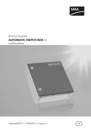
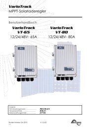
![SCHOTT PROTECT POLY 175-185 data sheet_D[...] - bk solar](https://img.yumpu.com/1309848/1/186x260/schott-protect-poly-175-185-data-sheet-d-bk-solar.jpg?quality=85)