V5124-581-04 _ Einputzadapter_Sprachen.qxd
V5124-581-04 _ Einputzadapter_Sprachen.qxd
V5124-581-04 _ Einputzadapter_Sprachen.qxd

Create successful ePaper yourself
Turn your PDF publications into a flip-book with our unique Google optimized e-Paper software.
<strong>Einputzadapter</strong>, 5124 03, 5125 03, 5126 03<br />
Für den flächenbündigen Einbau des M-PLAN II<br />
Adapter for flush-mounting, 5124 03, 5125 03, 5126 03<br />
For flush-mounted installation of M-PLAN II<br />
Boîtier d'encastrement, 5124 03, 5125 03, 5126 03<br />
Pour le montage affleurant du M-PLAN II<br />
Adattatore da incasso, 5124 03, 5125 03, 5126 03<br />
Per il montaggio a filo superficie dell'M-PLAN II<br />
Adaptador para empotrar, 5124 03, 5125 03, 5126 03<br />
Para el montaje a ras del M-PLAN II<br />
Adaptadores embutidos, 5124 03, 5125 03, 5126 03<br />
Para a montagem ao nível da superfície da M-PLAN II<br />
Inbouwadapter, 5124 03, 5125 03, 5126 03<br />
Voor gelijkliggende inbouw van de M-PLAN II<br />
D<br />
GB<br />
F<br />
I<br />
E<br />
P<br />
NL<br />
2
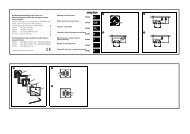
Gebrauchsanweisung 4<br />
Operating instructions 12<br />
Notice d`utilisation 20<br />
Istruzioni d´uso 28<br />
Instrucciones de servicio 36<br />
Instruções de serviço 44<br />
Gebruiksaanwijzing 52<br />
D<br />
GB<br />
F<br />
I<br />
E<br />
P<br />
NL<br />
3<br />
4<br />
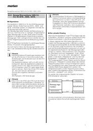
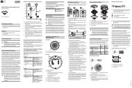
Einführung<br />
Mit dem <strong>Einputzadapter</strong> (Artikel-Nr.:<br />
512x 03) von Merten montieren Sie<br />
den M-PLAN II flächenbündig auf<br />
Gipskartonplatte oder auf<br />
Mauerwerk.<br />
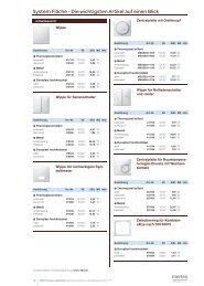
Übersicht der Einbaumöglichkeiten:<br />
A<br />
B<br />
C<br />
D<br />
E<br />
F<br />
G<br />
H<br />
A Gipskarton<br />
platte<br />
B Schraube<br />
C Mauerwerk<br />
D Nagel<br />
E Fuß<br />
F Edelputz<br />
G Fliesen<br />
H Tapete
A<br />
B<br />
C<br />
D<br />
A<br />
B<br />
C<br />
D<br />
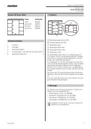
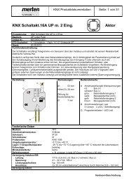
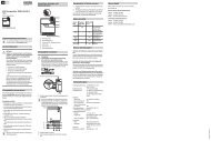
Aufbau auf unterschiedlichen<br />
Wänden<br />
Hohlwand-Installation<br />
Verwenden Sie den <strong>Einputzadapter</strong><br />
bei Hohlwand-Installationen.<br />
Montieren Sie ihn auf die<br />
Gipskartonplatte.<br />
A <strong>Einputzadapter</strong><br />
B Gerätedose<br />
C Gipskartonplatte<br />
D Leitung<br />
Unterputz-Installation<br />
Verwenden Sie den <strong>Einputzadapter</strong><br />
für Unterputz-Installationen.<br />
Montieren Sie ihn auf Mauerwerk.<br />
A <strong>Einputzadapter</strong><br />
B Gerätedose<br />
C Mauerwerk<br />
D Leitung<br />
5<br />
6<br />
E<br />
F<br />
! "<br />
§<br />
A<br />
B<br />
C<br />
D<br />
A<br />
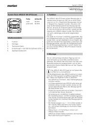
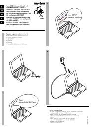
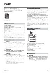
Anpassen an Einbausituation:<br />
Technische Informationen:<br />
- Die Ausgleichshöhe der fertigen<br />
Wandoberfläche ist von 9,5 - 17,5<br />
mm über Einlegeplättchen und<br />
Ausgleichskasten zu variieren.<br />
- Die Ausgleichshöhe je<br />
Einlegeplättchen beträgt<br />
1,2 mm.<br />
A Fertige Wandoberfläche<br />
B <strong>Einputzadapter</strong><br />
C Einlegeplättchen<br />
D Ausgleichskasten<br />
E min. 9,5 mm<br />
F max. 17,5 mm<br />
Beispielbilder:<br />
! = Ausgleichshöhe von 9,5 mm<br />
durch <strong>Einputzadapter</strong> (min.)<br />
" = Ausgleichshöhe von 12,5 mm<br />
durch <strong>Einputzadapter</strong> +<br />
1 Einlegeplättchen und<br />
Ausgleichskasten<br />
§ = Ausgleichshöhe von 17,5 mm<br />
durch <strong>Einputzadapter</strong> +<br />
5 Einlegeplättchen und<br />
Ausgleichskasten (max.)
!<br />
"<br />
§<br />
Montage des<br />
<strong>Einputzadapter</strong>s:<br />
!<br />
Dosen bündig zur Rohwand einbauen.<br />
Hilfslinien oben und unten einzeichnen.<br />
Dosen mit der Wasserwaage an<br />
Hilfslinien ausrichten.<br />
Hinweis:<br />
Vorhandene Geräteschrauben aus<br />
den Dosen entfernen!<br />
"<br />
<strong>Einputzadapter</strong> oben und unten<br />
mit den Nasen an Hilfslinien ausrichten.<br />
§<br />
<strong>Einputzadapter</strong> auf Gipskartonplatte<br />
schrauben oder auf<br />
Mauerwerk vernageln.<br />
Anpassen der <strong>Einputzadapter</strong>höhe<br />
an die Einbausituation von 9,5 -<br />
17,5 mm. (Siehe Seite 6)<br />
Hinweis:<br />
Die Oberkante des <strong>Einputzadapter</strong>s<br />
muss bündig mit der fertigen Wandoberfläche<br />
(z.B. Edelputz, Tapette,<br />
Fliesen, usw.) sein.<br />
7<br />
!a<br />
!b<br />
8<br />
Einbau des M-PLAN II mit<br />
dem <strong>Einputzadapter</strong><br />
Erklärt anhand von drei Beispielen:<br />
I = Gipskartonwände tapezieren<br />
II = Gipskartonwände verputzen<br />
III = Verfliesen<br />
I Gipskartonwände tapezieren<br />
!a<br />
Die Ausgleichshöhe beträgt in diesem<br />
Beispiel 9,5 mm<br />
(Siehe Beispielbilder auf Seite 6).<br />
Verputzschutz in <strong>Einputzadapter</strong><br />
einlegen.<br />
Zweite Gipskartonplatte zuschneiden<br />
und aufbringen.<br />
!b<br />
Freiraum beispachteln.<br />
Verputzschutz entnehmen.<br />
Anschließend die Gipskartonplatte<br />
tapezieren.<br />
Einsätze installieren und mit beigelegten<br />
Geräteschrauben befestigen.<br />
Rahmen und Abdeckung aufbringen.
!c<br />
"a<br />
"b<br />
!c<br />
Fertig eingebauter M-PLAN II auf<br />
tapezierter Gipskartonwand.<br />
II Gipskartonwände verputzen<br />
"a<br />
Hinweis:<br />
Höhe des <strong>Einputzadapter</strong>s mit dem<br />
Verputzer abstimmen.<br />
Die Ausgleichshöhe beträgt in diesem<br />
Beispiel 12,5 mm<br />
(Siehe Beispielbilder auf Seite 6).<br />
Einlegeplättchen und Ausgleichskasten<br />
mit beigelegten Geräteschrauben<br />
anschrauben.<br />
"b<br />
Verputzschutz an der Perforierung<br />
abreißen.<br />
Verputzschutz mit der größeren<br />
Seite nach oben in <strong>Einputzadapter</strong><br />
einlegen.<br />
Anschließend verputzen.<br />
9<br />
"c<br />
§a<br />
10<br />
Hinweis:<br />
Der Putz muss bündig mit der<br />
umlaufenden Kante des <strong>Einputzadapter</strong>s<br />
sein.<br />
Verputzschutz danach entnehmen.<br />
Geräteschrauben rausschrauben.<br />
Einsätze installieren und mit beigelegten<br />
Geräteschrauben befestigen.<br />
Rahmen und Abdeckung aufbringen.<br />
"c<br />
Fertig eingebauter M-PLAN II auf<br />
verputzter Gipskartonwand.<br />
III Verfliesen<br />
§a<br />
Hinweis:<br />
Höhe des <strong>Einputzadapter</strong>s mit dem<br />
Fliesenleger abstimmen.<br />
Die Ausgleichshöhe beträgt in diesem<br />
Beispiel 9,5 mm<br />
(Siehe Beispielbilder auf Seite 6).<br />
Die 4 Füße des <strong>Einputzadapter</strong>s<br />
an Sollbruchstelle abbrechen.
§b<br />
§c<br />
<strong>Einputzadapter</strong> innen mit 4<br />
Schrauben montieren.<br />
Hinweis:<br />
Schrauben müssen bündig zur<br />
Innenfläche sein.<br />
§b<br />
Verputzschutz in <strong>Einputzadapter</strong><br />
einlegen.<br />
Anschließend verputzen und verfliesen.<br />
Verputzschutz entnehmen.<br />
Einsätze installieren.<br />
Rahmen und Abdeckung aufbringen.<br />
§c<br />
Fertig eingebauter M-PLAN II auf<br />
verfliester Wand.<br />
11<br />
12<br />
Introduction<br />
The adapter for flush-mounting<br />
(art. no.: 512x 03) available from<br />
Merten makes it possible to flushmount<br />
M-PLAN II in gypsum plasterboard<br />
or masonry.<br />
Overview of fitting options:<br />
A<br />
B<br />
C<br />
D<br />
E<br />
F<br />
G<br />
H<br />
A Gypsum plasterboard<br />
B Screw<br />
C Masonry<br />
D Nail<br />
E Foot<br />
F Facing plaster<br />
G Tiles<br />
H Wallpaper
A<br />
B<br />
C<br />
D<br />
A<br />
B<br />
C<br />
D<br />
Fitting on various<br />
types of wall<br />
Cavity wall installation<br />
Use the adapter for installation<br />
in cavity walls. It is mounted into<br />
the gypsum plasterboard.<br />
A Adapter for flush-mounting<br />
B Device socket<br />
C Gypsum plasterboard<br />
D Cable<br />
Flush-mounted installation<br />
in plastered walls<br />
Use the adapter for flush-mounted<br />
installation in plastered walls. It is<br />
mounted into the masonry.<br />
A Adapter for flush-mounting<br />
B Device socket<br />
C Masonry<br />
D Cable<br />
13<br />
14<br />
E<br />
F<br />
! "<br />
§<br />
A<br />
B<br />
C<br />
D<br />
A<br />
Adaptation<br />
to the fitting site:<br />
Technical information:<br />
- The compensation height for<br />
the finished wall surface can be<br />
altered by between 9.5 - 17.5 mm<br />
using intermediate plates and<br />
boxes.<br />
- The compensation height per<br />
intermediate plate is 1.2 mm.<br />
A Finished wall surface<br />
B Adapter for flush-mounting<br />
C Intermediate plate<br />
D Box<br />
E min. 9.5 mm<br />
F max. 17.5 mm<br />
Example diagrams:<br />
! = Height compensation<br />
of 9.5 mm using the adapter<br />
for flush-mounting (min.)<br />
" = Height compensation<br />
of 12.5 mm using adapter<br />
+ 1 intermediate plate<br />
and box<br />
§ = Height compensation<br />
of 17.5 mm using adapter<br />
+ 5 intermediate plates<br />
and box (max.)
!<br />
"<br />
§<br />
Installing the adapter<br />
for flush-mounting:<br />
!<br />
Install the sockets flush<br />
to the unfinished wall.<br />
Draw guidance lines to the top<br />
and bottom.<br />
Align the sockets to the guidance<br />
lines using a spirit level.<br />
Note:<br />
Remove any device screws from<br />
the sockets!<br />
"<br />
Align the nibs of the adapter<br />
to the guidance lines top and bottom.<br />
§<br />
Screw the adapter to the<br />
gypsum plasterboard or nail it<br />
to the masonry.<br />
Adapt the height of the adapter<br />
by 9.5 - 17.5 mm depending on<br />
the installation site. (See page 14)<br />
Note:<br />
The top edge of the adapter must<br />
be flush with the finished surface of<br />
the wall (e.g. facing plaster, wallpaper,<br />
tiles etc.)<br />
15<br />
!a<br />
!b<br />
16<br />
Installing the M-PLAN II with<br />
the adapter for flush-mounting<br />
This is demonstrated using three<br />
examples:<br />
I = Wallpapering gypsum plasterboard<br />
walls<br />
II = Plastering gypsum plasterboard<br />
walls<br />
III = Tiling<br />
I Wallpapering gypsum<br />
plasterboard walls<br />
!a<br />
The compensation height in this<br />
example is 9.5 mm (see the example<br />
diagrams on page 14).<br />
Insert the plastering shield in<br />
the adapter.<br />
Cut the second gypsum plasterboard<br />
to size and fit it.<br />
!b<br />
Level out the free space with<br />
plaster.<br />
Remove the plastering shield.<br />
Then wallpaper the gypsum plasterboard.<br />
Install the inserts and fasten<br />
with the device screws supplied.<br />
Fit the frame and cover.
!c<br />
"a<br />
"b<br />
!c<br />
Fully fitted M-PLAN II on wallpapered<br />
gypsum plasterboard.<br />
II Plastering gypsum<br />
plasterboard walls<br />
"a<br />
Note:<br />
Confirm the height of the adapter<br />
with the plasterer.<br />
The compensation height in this<br />
example is 12.5 mm (See the example<br />
diagrams on page 14).<br />
Screw on the intermediate plates<br />
and boxes with the device screws<br />
provided.<br />
"b<br />
Tear off the plastering shield<br />
at the perforation.<br />
Insert the plastering shield into<br />
the adapter with the larger side<br />
upwards.<br />
Then, proceed with plastering<br />
the wall.<br />
17<br />
"c<br />
§a<br />
18<br />
Note:<br />
The plaster must be flush with the<br />
surrounding edge of the adapter.<br />
Remove the plastering shield<br />
afterwards.<br />
Unscrew the device screws.<br />
Install the inserts and fasten<br />
with the device screws supplied.<br />
Fit the frame and cover.<br />
"c<br />
Fully fitted M-PLAN II on plastered<br />
gypsum plasterboard.<br />
III Tiling<br />
§a<br />
Note:<br />
Confirm the height of the adapter<br />
with the tiler.<br />
The compensation height in this<br />
example is 9.5 mm (see the example<br />
diagrams on page 14).<br />
Break off the 4 feet of the adapter<br />
at the appropriate point.
§b<br />
§c<br />
Install the adapter on the inside<br />
with 4 screws.<br />
Note:<br />
The screws must be flush to the<br />
inside surface.<br />
§b<br />
Insert the plastering shield in the<br />
adapter.<br />
Then, proceed with plastering and<br />
tiling the wall.<br />
Remove the plastering shield.<br />
Install the inserts.<br />
Fit the frame and cover.<br />
§c<br />
Fully fitted M-PLAN II on tiled wall.<br />
19<br />
20<br />
Introduction<br />
Le boîtier d’encastrement (N° de<br />
référence : 512x 03) de Merten permet<br />
le montage affleurant du<br />
M-PLAN II sur les plaques de plâtre<br />
ou directement sur les murs.<br />
Aperçu des possibilités<br />
de montage :<br />
A<br />
B<br />
C<br />
D<br />
E<br />
F<br />
G<br />
H<br />
A Plaque de plâtre<br />
B Vis<br />
C Mur<br />
D Clou<br />
E Pied<br />
F Enduit de luxe<br />
G Carrelage<br />
H Tapisserie
A<br />
B<br />
C<br />
D<br />
A<br />
B<br />
C<br />
D<br />
Montage sur des cloisons<br />
de différents types<br />
Installation sur mur creux<br />
Pour les installations sur mur creux,<br />
utilisez le boîtier d’encastrement.<br />
Montez-le sur la plaque de plâtre.<br />
A Boîtier d’encastrement<br />
B Prise<br />
C Plaque de plâtre<br />
D Câble<br />
Installation sous enduit<br />
Pour les installations sous enduit,<br />
utilisez le boîtier d’encastrement.<br />
Montez-le sur le mur.<br />
A Boîtier d’encastrement<br />
B Prise<br />
C Mur<br />
D Câble<br />
21<br />
22<br />
E<br />
F<br />
! "<br />
§<br />
A<br />
B<br />
C<br />
D<br />
A<br />
Adaptation aux conditions<br />
de montage :<br />
Caractéristiques techniques :<br />
- L’utilisation de plaquettes intermédiaires<br />
et les socles d’ajustage<br />
permet de faire varier la hauteur<br />
d’ajustement de la surface du<br />
mur entre 9,5 et 17,5 mm.<br />
- Chaque plaquette intermédiaire<br />
utilisée permet un ajustement<br />
de 1,2 mm.<br />
A Surface de la cloison finie<br />
B Boîtier d’encastrement<br />
C Plaquettes intermédiaires<br />
D Socle d’ajustage<br />
E min. 9,5 mm<br />
F max. 17,5 mm<br />
Exemples illustrés :<br />
! = Hauteur d’ajustement<br />
de 9,5 mm grâce au boîtier<br />
d’encastrement (min.)<br />
" = Hauteur d’ajustement<br />
de 12,5 mm grâce au boîtier<br />
d’encastrement +<br />
1 plaquette intermédiaire<br />
et socle d’ajustage<br />
§ = Hauteur d’ajustement<br />
de 17,5 mm grâce au boîtier<br />
d’encastrement +<br />
5 plaquettes intermédiaires<br />
et socle d’ajustage (max.)
!<br />
"<br />
§<br />
Montage du boîtier<br />
d’encastrement :<br />
!<br />
Encastrer les prises dans le mur<br />
de façon à ce qu’elles ne dépassent<br />
pas.<br />
Tracer des lignes de repère audessus<br />
et au-dessous.<br />
Aligner les prises selon les lignes<br />
de repère et à l’aide du niveau<br />
à bulle.<br />
Remarque :<br />
Retirez les vis présentes sur les prises<br />
!<br />
"<br />
Aligner le boîtier d’encastrement<br />
en haut et en bas de façon à ce<br />
que les crochets soient dans<br />
l’alignement des lignes de repère<br />
tracées.<br />
§<br />
Visser le boîtier d’encastrement<br />
sur la plaque de plâtre ou le clouer<br />
sur le mur.<br />
Adapter la hauteur du boîtier<br />
d’encastrement, de 9,5 à<br />
17,5 mm, à la situation de montage.<br />
(Voir chapitre 22)<br />
Remarque :<br />
Le bord du boîtier d’encastrement ne<br />
doit pas dépasser de la surface de la<br />
cloison, une fois celle-ci finie (p. ex.<br />
crépi, tapisserie, carrelage, etc.).<br />
23<br />
!a<br />
!b<br />
24<br />
Montage du M-PLAN II<br />
sur le boîtier d’encastrement<br />
Explication à l’aide de trois exemples :<br />
I = Cloisons en plaques de plâtre<br />
tapissées<br />
II = Cloisons en plaques de plâtre<br />
enduites<br />
III = Carrelage<br />
I Cloisons en plaques<br />
de plâtre tapissées<br />
!a<br />
Dans cet exemple, la hauteur d’ajustement<br />
est de 9,5 mm<br />
(Voir exemples page 22).<br />
Emboîter la protection contre l’enduit<br />
dans le boîtier d’encastrement.<br />
Découper la deuxième plaque<br />
de plâtre et la poser.<br />
!b<br />
Enduire l’espace libre.<br />
Retirer la protection du boîtier.<br />
Tapisser ensuite la plaque de plâtre.<br />
Monter les composants et les<br />
fixer à l’aide des vis jointes prévues<br />
à cet effet.<br />
Poser le cadre et le revêtement.
!c<br />
"a<br />
"b<br />
!c<br />
M-PLAN II monté sur cloison<br />
en plaque de plâtre tapissée.<br />
II Cloisons en plaque<br />
de plâtre enduites<br />
"a<br />
Remarque :<br />
S’entendre avec le crépisseur sur<br />
la hauteur d’ajustement du boîtier<br />
d’encastrement.<br />
Dans cet exemple, la hauteur<br />
d’ajustement est de 12,5 mm<br />
(Voir exemples illustrés page 22).<br />
Visser les plaquettes intermédiaires<br />
et le socle d’ajustage à l’aide des<br />
vis fournies prévues à cet effet.<br />
"b<br />
Déchirer la protection du boîtier<br />
au niveau des perforations.<br />
Emboîter la protection contre l’enduit<br />
dans le boîtier d’encastrement<br />
de façon<br />
à ce que le coté le plus large<br />
soit orienté vers le haut.<br />
Puis enduire.<br />
25<br />
"c<br />
§a<br />
26<br />
Remarque :<br />
L’enduit doit être au même niveau que<br />
le rebord du boîtier d’encastrement.<br />
Retirer ensuite la protection<br />
du boîtier.<br />
Dévisser entièrement les vis.<br />
Monter les composants et<br />
les fixer à l’aide des vis jointes<br />
prévues à cet effet.<br />
Poser le cadre et le revêtement.<br />
"c<br />
M-PLAN II monté sur cloison<br />
en plaque de plâtre enduite.<br />
III Carrelage<br />
§a<br />
Remarque :<br />
S’entendre avec le carreleur sur<br />
la hauteur d’ajustement du boîtier<br />
d’encastrement.<br />
Dans cet exemple, la hauteur d’ajustement<br />
est de 9,5 mm<br />
(Voir exemples illustrés page 22).<br />
Rompre les 4 pieds du boîtier<br />
d’encastrement au niveau des<br />
points de rupture prescrits.
§b<br />
§c<br />
Visser le boîtier d’encastrement<br />
à l’intérieur, à l’aide de 4 vis.<br />
Remarque :<br />
Les vis ne doivent pas dépasser<br />
de la surface intérieure.<br />
§b<br />
Emboîter la protection contre l’enduit<br />
dans le boîtier d’encastrement.<br />
Puis enduire et carreler.<br />
Retirer la protection du boîtier.<br />
Monter les composants.<br />
Poser le cadre et le revêtement.<br />
§c<br />
M-PLAN II monté sur cloison carrelée.<br />
27<br />
28<br />
Introduzione<br />
Grazie all’adattatore da incasso (articolo<br />
no.: 512x 03) della Merten è<br />
possibile montare l’M-PLAN II a filo<br />
superficie su lastre di cartongesso o<br />
su pareti in muratura.<br />
Panoramica delle possibilità<br />
di montaggio:<br />
A<br />
B<br />
C<br />
D<br />
E<br />
F<br />
G<br />
H<br />
A Lastra di cartongesso<br />
B Vite<br />
C Parete in muratura<br />
D Chiodo<br />
E Piedino<br />
F Intonaco di rifinitura<br />
G Piastrella<br />
H Tappezzeria
A<br />
B<br />
C<br />
D<br />
A<br />
B<br />
C<br />
D<br />
Montaggio su diversi tipi<br />
di parete<br />
Installazione su parete cava<br />
Utilizzare l’adattatore da incasso<br />
per l’installazione su parete cava.<br />
In questo caso esso va montato<br />
sulla lastra di cartongesso.<br />
A Adattatore da incasso<br />
B Scatola<br />
C Lastra di cartongesso<br />
D Cavo<br />
Installazione sotto intonaco<br />
Utilizzare l’adattatore da incasso<br />
per l’installazione sotto intonaco.<br />
In questo caso esso va montato<br />
sulla parete in muratura.<br />
A Adattatore da incasso<br />
B Scatola<br />
C Parete in muratura<br />
D Cavo<br />
29<br />
30<br />
E<br />
F<br />
! "<br />
§<br />
A<br />
B<br />
C<br />
D<br />
A<br />
Adattamento alla situazione<br />
di montaggio:<br />
Informazioni tecniche:<br />
- L’altezza di compensazione della<br />
superficie della parete finita deve<br />
essere 9,5 - 17,5 mm al di sopra<br />
delle piastrine d’inserimento<br />
e della scatola di compensazione.<br />
- L’altezza di compensazione<br />
per ogni piastrina d’inserimento<br />
è di 1,2 mm.<br />
A Superficie della parete finita<br />
B Adattatore da incasso<br />
C Piastrina d’inserimento<br />
D Scatola di compensazione<br />
E min. 9,5 mm<br />
F max. 17,5 mm<br />
Figure di esempio:<br />
! = Altezza di compensazione<br />
di 9,5 mm mediante adattatore<br />
da incasso (min.)<br />
" = Altezza di compensazione<br />
di 12,5 mm mediante adattatore<br />
da incasso +<br />
1 piastrina d’inserimento<br />
e scatola di compensazione<br />
§ = Altezza di compensazione<br />
di 17,5 mm mediante adattatore<br />
da incasso +<br />
5 piastrine d’inserimento<br />
e scatola di compensazione<br />
(max.)
!<br />
"<br />
§<br />
Montaggio dell’adattatore<br />
da incasso:<br />
!<br />
Montare le scatole a filo con la<br />
parete grezza.<br />
Tracciare delle linee di riferimento<br />
sopra e sotto.<br />
Con una livella a bolla d’aria allineare<br />
le scatole alle linee di riferimento.<br />
Avvertenza:<br />
Rimuovere dalle scatole le viti eventualmente<br />
presenti!<br />
"<br />
Allineare i nasi dell’adattatore da<br />
incasso alle linee di riferimento<br />
sopra e sotto.<br />
§<br />
Fissare con delle viti l’adattatore<br />
da incasso sulla lastra di cartongesso,<br />
oppure con dei chiodi sulla<br />
parete in muratura.<br />
Adattare l’altezza dell’adattatore<br />
da incasso alla situazione di montaggio<br />
di 9,5 - 17,5 mm. (Vedi pagina<br />
6)<br />
Avvertenza:<br />
Il bordo superiore dell’adattatore<br />
da incasso deve essere a filo con<br />
la superficie della parete finita<br />
(ad es. con l’intonaco di rifinitura,<br />
la tappezzeria, le piastrelle ecc.).<br />
31<br />
!a<br />
!b<br />
32<br />
Montaggio dell’M-PLAN II<br />
con l’adattatore da incasso<br />
A titolo di spiegazione sono riportati<br />
tre esempi:<br />
I = Tappezzatura di pareti di cartongesso<br />
II = Intonacatura di pareti di cartongesso<br />
III = Piastrellatura<br />
I Tappezzatura di pareti<br />
di cartongesso<br />
!a<br />
In questo esempio l’altezza di compensazione<br />
è di 9,5 mm<br />
(vedi figure di esempio a pagina 30).<br />
Inserire nell’adattatore da incasso<br />
la protezione per intonacatura.<br />
Tagliare e applicare la seconda lastra<br />
di cartongesso.<br />
!b<br />
Riempire di stucco lo spazio libero.<br />
Togliere la protezione per intonacatura.<br />
Tappezzare la lastra di cartongesso.<br />
Installare gli inserti e fissarli con<br />
le viti comprese nella fornitura.<br />
Applicare la cornice e il rivestimento.
!c<br />
"a<br />
"b<br />
!c<br />
M-PLAN II montato su parete<br />
di cartongesso tappezzata.<br />
II Intonacatura di pareti<br />
di cartongesso<br />
"a<br />
Avvertenza:<br />
L’altezza dell’adattatore da incasso<br />
deve essere concordata con l’intonacatore.<br />
In questo esempio l’altezza di compensazione<br />
è di 12,5 mm<br />
(vedi figure di esempio a pagina 30).<br />
Avvitare le piastrine d’inserimento<br />
e la scatola di compensazione con<br />
le viti comprese nella fornitura.<br />
"b<br />
Strappare la protezione per intonacatura<br />
lungo la perforazione.<br />
Inserire nell’adattatore da incasso<br />
la protezione per intonacatura con<br />
il lato più grande verso l’alto.<br />
Procedere all’intonacatura.<br />
33<br />
"c<br />
§a<br />
34<br />
Avvertenza:<br />
L’intonaco deve essere a filo con<br />
i bordi dell’adattatore da incasso.<br />
Togliere quindi la protezione per<br />
intonacatura.<br />
Svitare e togliere le viti.<br />
Installare gli inserti e fissarli con<br />
le viti comprese nella fornitura.<br />
Applicare la cornice e il rivestimento.<br />
"c<br />
M-PLAN II montato su parete di cartongesso<br />
intonacata.<br />
III Piastrellatura<br />
§a<br />
Avvertenza:<br />
L’altezza dell’adattatore da incasso<br />
deve essere concordata con il piastrellista.<br />
In questo esempio l’altezza di compensazione<br />
è di 9,5 mm<br />
(vedi figure di esempio a pagina 30).<br />
Rompere i 4 piedini dell’adattatore<br />
da incasso nei punti di rottura previsti.
§b<br />
§c<br />
Montare l’adattatore da incasso<br />
fissandolo con 4 viti all’interno.<br />
Avvertenza:<br />
Le viti devono essere a filo con la<br />
superficie interna.<br />
§b<br />
Inserire nell’adattatore da incasso<br />
la protezione per intonacatura.<br />
Intonacare e piastrellare.<br />
Togliere la protezione per intonacatura.<br />
Installare gli inserti.<br />
Applicare la cornice e il rivestimento.<br />
§c<br />
M-PLAN II montato su parete piastrellata.<br />
35<br />
36<br />
Introducción<br />
Con el adaptador para empotrar<br />
(Ref.: 512x 03) de Merten, puede<br />
usted montar el M PLAN II a ras<br />
en paneles de cartón yeso o en<br />
mampostería.<br />
Esquema general de las<br />
posibilidades de montaje:<br />
A<br />
B<br />
C<br />
D<br />
E<br />
F<br />
G<br />
H<br />
A Panel de cartón<br />
yeso<br />
B Tornillo<br />
C Mampostería<br />
D Clavo<br />
E Pie<br />
F Revoque fino<br />
G Azulejos<br />
H Papel pintado
A<br />
B<br />
C<br />
D<br />
A<br />
B<br />
C<br />
D<br />
Montaje en diferentes tipos<br />
de paredes<br />
Instalación en paredes huecas<br />
Utilice el adaptador para empotrar<br />
para instalaciones en paredes huecas.<br />
Móntelo en paneles de cartón<br />
yeso.<br />
A Adaptador para empotrar<br />
B Caja de enchufe del aparato<br />
C Panel de cartón yeso<br />
D Cable<br />
Instalación revocada<br />
Utilice el adaptador para empotrar<br />
en instalaciones revocadas.<br />
Móntelo sobre mampostería.<br />
A Adaptador para empotrar<br />
B Caja de enchufe del aparato<br />
C Mampostería<br />
D Cable<br />
37<br />
38<br />
E<br />
F<br />
! "<br />
§<br />
A<br />
B<br />
C<br />
D<br />
A<br />
Adaptación a la situación<br />
de montaje:<br />
Informaciones técnicas:<br />
- La profundidad de nivelación de<br />
la superficie de la pared terminada<br />
puede variar entre los 9,5 - 17,5 mm<br />
sobre la placa intermedia y la caja<br />
de nivelación.<br />
- La profundidad de nivelación de cada<br />
placa intermedia es de 1,2 mm.<br />
A Superficie de la pared terminada<br />
B Adaptador para empotrar<br />
C Placa intermedia<br />
D Caja de nivelación<br />
E mín. 9,5 mm<br />
F máx.17,5 mm<br />
Esquemas ilustrativos:<br />
! = Profundidad de nivelación<br />
de 9,5 mm obtenida con<br />
el adaptador para empotrar<br />
(mín.)<br />
" = Profundidad de nivelación<br />
de 12,5 mm obtenida con el<br />
adaptador para empotrar +<br />
1 placa intermedia y la caja<br />
de nivelación<br />
§ = Profundidad de nivelación<br />
de 17,5 mm obtenida con el<br />
adaptador para empotrar +<br />
5 placas intermedias y la caja<br />
de nivelación (máx.)
!<br />
"<br />
§<br />
Montaje del adaptador<br />
para empotrar:<br />
!<br />
Monte las cajas de enchufe<br />
a ras en la pared en bruto.<br />
Trace líneas auxiliares arriba<br />
y abajo.<br />
Alinee las cajas de enchufe con<br />
las líneas auxiliares con la ayuda<br />
de un nivel.<br />
Nota:<br />
Retire los tornillos del equipo que<br />
haya en las cajas de enchufe.<br />
"<br />
Alinee el adaptador para empotrar<br />
con las líneas auxiliares, arriba y<br />
abajo, con ayuda de las pestañas.<br />
§<br />
Clave el adaptador para empotrar<br />
a un panel de cartón yeso o en<br />
mampostería.<br />
Ajuste la profundidad del adaptador<br />
para empotrar a la situación<br />
de 9,5 -17,5 mm.<br />
(Véase la página 38)<br />
Nota:<br />
El borde de arriba del adaptador<br />
para empotrar debe estar a ras con<br />
la superficie de la pared terminada<br />
(p. ej. revoque fino, papel pintado,<br />
azulejos, etc.)<br />
39<br />
!a<br />
!b<br />
40<br />
Montaje del M-PLAN II con<br />
el adaptador para empotrar<br />
Explicación a través de tres ejemplos:<br />
I = Empapelar paredes de cartón<br />
yeso<br />
II = Revocar paredes de cartón yeso<br />
III = Alicatar<br />
I Empapelado de paredes<br />
de cartón yeso<br />
!a<br />
La profundidad de nivelación es,<br />
en este ejemplo, 9,5 mm<br />
(Véanse los esquemas de la pág.<br />
38).<br />
Ponga la protección para revocar<br />
en el adaptador para empotrar.<br />
Corte y aplique el segundo panel<br />
de cartón yeso.<br />
!b<br />
Emplastezca los huecos.<br />
Retire la protección para revocar.<br />
A continuación empapele el panel<br />
de cartón yeso.<br />
Inserte las piezas y fíjelas con los<br />
tornillos del equipo.<br />
Coloque el marco y la cubierta.
!c<br />
"a<br />
"b<br />
!c<br />
M-PLAN II completamente montado<br />
en pared empapelada de cartón<br />
yeso.<br />
II Revoque de paredes<br />
de cartón yeso<br />
"a<br />
Nota:<br />
Ajuste al revoque la profundidad<br />
del adaptador para empotrar.<br />
La profundidad de nivelación<br />
en este ejemplo es 12,5 mm.<br />
(Véase el esquma de la pág. 38)<br />
Atornille las placas intermedias<br />
y la caja de nivelación con los tornillos<br />
del equipo.<br />
"b<br />
Arranque la protección para revocar<br />
del agujero perforado.<br />
Coloque la protección para revocar<br />
en el adaptador para empotrar,<br />
con el lado más grande hacia arriba.<br />
A continuación, revoque.<br />
41<br />
"c<br />
§a<br />
42<br />
Nota:<br />
El revoque tiene que estar a ras con<br />
el lado exterior del adaptador para<br />
empotrar.<br />
Retire después la protección para<br />
revocar.<br />
Destornillar los tornillos del equipo.<br />
Inserte las piezas y fíjelas con<br />
los tornillos del equipo.<br />
Coloque el marco y la cubierta.<br />
"c<br />
M-PLAN II completamente montado<br />
en pared revocada de cartón<br />
yeso.<br />
III Alicatado<br />
§a<br />
Nota:<br />
Ajuste al embaldosado la profundidad<br />
del adaptador para empotrar.<br />
La profundidad de nivelación es,<br />
en este ejemplo, 9,5 mm<br />
(Véanse los esquemas de la pág.<br />
38)<br />
Rompa los 4 pies del adaptador<br />
para empotrar por los puntos teóricos<br />
de rotura.
§b<br />
§c<br />
Monte dentro el adaptador para<br />
empotrar con 4 tornillos.<br />
Nota:<br />
Los tornillos han de estar a ras con<br />
la superficie interior.<br />
§b<br />
Coloque la protección para revocar<br />
en el adaptador para empotrar.<br />
A continuación, revoque y alicate.<br />
Retire la protección para revocar.<br />
Inserte las piezas.<br />
Coloque el marco y la cubierta.<br />
§c<br />
M-PLAN II completamente montado<br />
en una pared alicatada.<br />
43<br />
44<br />
Introdução<br />
Com o adaptador embutido<br />
(art. n.º 512x 03) da Merten, poderá<br />
montar a M-PLAN II ao nível da<br />
superfície em placas de gesso cartonado<br />
ou alvenaria.<br />
Vista geral das possibilidades<br />
de montagem:<br />
A<br />
B<br />
C<br />
D<br />
E<br />
F<br />
G<br />
H<br />
A Placa de gesso<br />
cartonado<br />
B Parafuso<br />
C Alvenaria<br />
D Prego<br />
E Pé<br />
F Reboco fino<br />
G Azulejos<br />
H Papel de parede
A<br />
B<br />
C<br />
D<br />
A<br />
B<br />
C<br />
D<br />
Montagem em diversos tipos<br />
de parede<br />
Instalação em paredes ocas<br />
Utilize o adaptador embutido<br />
nas instalações em paredes ocas.<br />
Monte-o em placas de gesso cartonado.<br />
A Adaptador embutido<br />
B Caixa de aparelhagem<br />
C Placa de gesso cartonado<br />
D Cabo<br />
Instalação em paredes rebocadas<br />
Utilize o adaptador embutido nas<br />
instalações em paredes rebocadas.<br />
Monte-o em alvenaria.<br />
A Adaptador embutido<br />
B Caixa de aparelhagem<br />
C Alvenaria<br />
D Cabo<br />
45<br />
46<br />
E<br />
F<br />
! "<br />
§<br />
A<br />
B<br />
C<br />
D<br />
A<br />
Adaptar à situação<br />
de instalação:<br />
Informações técnicas:<br />
- A altura de compensação da<br />
superfície na parede pronta<br />
é de 9,5 - 17,5 mm regulável através<br />
de distanciadores<br />
e a caixa compensadora.<br />
- A altura de compensação de cada<br />
distanciador é de 1,2 mm.<br />
A Superfície pronta da parede<br />
B Adaptador embutido<br />
C Distanciadores<br />
D Caixa compensadora<br />
E mín. 9,5 mm<br />
F máx. 17,5 mm<br />
Figuras de exemplo:<br />
! = altura de compensação<br />
de 9,5 mm com adaptador<br />
embutido (mín.)<br />
" = altura de compensação<br />
de 12,5 mm com adaptador<br />
embutido +<br />
1 distanciador e caixa de compensação<br />
§ = altura de compensação<br />
de 17,5 mm com adaptador<br />
embutido +<br />
5 distanciadores e caixa<br />
de compensação (máx.)
!<br />
"<br />
§<br />
Montagem do adaptador<br />
embutido:<br />
!<br />
Montar as caixas de montagem<br />
ao nível da parede em bruto.<br />
Marcar as linhas de ajuda em<br />
cima e em baixo.<br />
Alinhar as caixas de montagem<br />
pelas linhas de ajuda usando<br />
um nível de bolha de ar.<br />
Nota:<br />
Retirar os parafusos existentes<br />
nas caixas!<br />
"<br />
Alinhar o adaptador embutido em<br />
cima e em baixo pelas linhas de<br />
ajuda através dos ressaltos.<br />
§<br />
Aparafusar o adaptador embutido<br />
à placa de gesso cartonado ou<br />
fixá-lo com pregos à alvenaria.<br />
Adaptar a altura do adaptador<br />
embutido à situação desde 9,5<br />
a 17,5 mm (Ver página 46).<br />
Nota:<br />
A margem superior do adaptador<br />
embutido tem de estar ao nível da<br />
superfície da parede pronta (p. ex.<br />
reboco final, papel de parede, azulejos,<br />
etc.).<br />
47<br />
!a<br />
!b<br />
48<br />
Montagem da M-PLAN II<br />
com o adaptador embutido<br />
Explicação com base em três<br />
exemplos:<br />
I = Aplicar papel de parede em<br />
paredes de gesso cartonado<br />
II = Rebocar paredes em gesso<br />
cartonado<br />
III = Assentar azulejos<br />
I Aplicar papel de parede<br />
em paredes de gesso cartonado<br />
!a<br />
Neste exemplo, a altura de compensação<br />
é de 9,5 mm (Ver figuras<br />
de exemplo na página 46).<br />
Colocar a protecção contra reboco<br />
no adaptador embutido.<br />
Recortar e aplicar a segunda placa<br />
de gesso cartonado.<br />
!b<br />
Preencher o espaço vazio com<br />
uma espátula.<br />
Retirar a protecção contra reboco.<br />
Em seguida, colocar papel<br />
de parede na placa de gesso cartonado.<br />
Instalar a aparelhagem e fixá-la<br />
com os parafusos fornecidos.<br />
Colocar o espelho e a tampa.
!c<br />
"a<br />
"b<br />
!c<br />
M-PLAN II montada em parede<br />
de gesso cartonado com papel<br />
de parede.<br />
II Rebocar paredes<br />
em gesso cartonado<br />
"a<br />
Nota:<br />
Definir a altura do adaptador embutido<br />
com o pedreiro.<br />
Neste exemplo, a altura de compensação<br />
é de 12,5 mm (Ver figuras<br />
de exemplo na página 46).<br />
Aparafusar os distanciadores<br />
e a caixa de compensação<br />
com os parafusos fornecidos.<br />
"b<br />
Remover a protecção contra reboco<br />
pela perfuração.<br />
Inserir a protecção contra reboco,<br />
com o lado maior virado para<br />
cima, no adaptador embutido.<br />
Em seguida, rebocar.<br />
49<br />
"c<br />
§a<br />
50<br />
Nota:<br />
O reboco deve estar ao nível da<br />
margem do adaptador embutido.<br />
Depois, retirar a protecção contra<br />
reboco.<br />
Desaparafusar os parafusos.<br />
Instalar a aparelhagem e fixá-la<br />
com os parafusos fornecidos.<br />
Colocar o espelho e a tampa.<br />
"c<br />
M-PLAN II montada em parede<br />
de gesso cartonado rebocado.<br />
III Assentamento de azulejos<br />
§a<br />
Nota:<br />
Definir a altura do adaptador embutido<br />
com o ladrilhador.<br />
Neste exemplo, a altura de compensação<br />
é de 9,5 mm (Ver figuras<br />
de exemplo na página 46).<br />
Quebrar os 4 pés do adaptador<br />
embutido pelos pontos de quebra<br />
predefinidos.
§b<br />
§c<br />
Montar o adaptador embutido<br />
pelo interior com 4 parafusos.<br />
Nota:<br />
Os parafusos devem estar alinhados<br />
com a superfície interior.<br />
§b<br />
Colocar a protecção contra reboco<br />
no adaptador embutido.<br />
Em seguida, rebocar e assentar<br />
os azulejos.<br />
Retirar a protecção contra reboco.<br />
Instalar a aparelhagem.<br />
Colocar o espelho e a tampa.<br />
§c<br />
M-PLAN II montada em parede<br />
com azulejos.<br />
51<br />
52<br />
Inleiding<br />
Met de inbouwadapter (artikelnr.<br />
512x 03) van Merten monteert<br />
u de M-PLAN II gelijkliggend op gipsplaten<br />
of gepleisterde muren.<br />
Overzicht van de<br />
inbouwmogelijkheden:<br />
A<br />
B<br />
C<br />
D<br />
E<br />
F<br />
G<br />
H<br />
A Gipsplaat<br />
B Bout<br />
C Gepleisterde<br />
muur<br />
D Spijker<br />
E Voet<br />
F Muurwerk<br />
G Tegels<br />
H Behang
A<br />
B<br />
C<br />
D<br />
A<br />
B<br />
C<br />
D<br />
Montage op verschillende<br />
wandsoorten<br />
Montage op een holle wand<br />
Maak bij installatie op een holle<br />
wand gebruik van een inbouwadapter<br />
en monteer deze op de gipsplaat.<br />
A Inbouwadapter<br />
B Apparatendoos<br />
C Gipsplaat<br />
D Leiding<br />
Inbouwmontage<br />
Maak bij inbouwmontage gebruik<br />
van de inbouwadapter en monteer<br />
deze op de gepleisterde muur.<br />
A Inbouwadapter<br />
B Apparatendoos<br />
C Gepleisterde muur<br />
D Leiding<br />
53<br />
54<br />
E<br />
F<br />
! "<br />
§<br />
A<br />
B<br />
C<br />
D<br />
A<br />
Aanpassen aan<br />
inbouwsituaties:<br />
Technische informatie:<br />
- De compensatiehoogte van het<br />
bewerkte wandoppervlak is met<br />
behulp van inlegplaatjes en compensatiekasten<br />
van 9,5 - 17,5 mm<br />
af te stellen.<br />
- De compensatiehoogte per inlegplaatje<br />
bedraagt 1,2 mm.<br />
A Bewerkt wandoppervlak<br />
B Inbouwadapter<br />
C Inlegplaatjes<br />
D Compensatiekast<br />
E min. 9,5 mm<br />
F max. 17,5 mm<br />
Voorbeelden:<br />
! = Compensatiehoogte van<br />
9,5 mm door inbouwadapter<br />
(min.)<br />
" = Compensatiehoogte van<br />
12,5 mm door inbouwadapter<br />
+ 1 inlegplaatje en compensatiekast<br />
§ = Compensatiehoogte van<br />
17,5 mm door inbouwadapter<br />
+ 5 inlegplaatjes en compensatiekast<br />
(max.)
!<br />
"<br />
§<br />
Montage van de<br />
inbouwadapter:<br />
!<br />
De dozen parallel aan de onbewerkte<br />
muur monteren.<br />
Hulplijnen aan boven- en onderzijde<br />
markeren.<br />
De dozen met behulp van de waterpas<br />
aan de hulplijnen uitrichten.<br />
Aanwijzing:<br />
Voorhanden schroeven uit de dozen<br />
verwijderen!<br />
"<br />
De inbouwadapter aan bovenen<br />
onderzijde met behulp van<br />
de houders aan de hulplijnen uitrichten.<br />
§<br />
De inbouwadapter op de gipsplaat<br />
schroeven of met spijkers aan de<br />
muur bevestigen.<br />
Aanpassen van de inbouwadapterhoogte<br />
aan de inbouwsituatie van<br />
9,5 - 17,5 mm. (zie pagina 54)<br />
Aanwijzing:<br />
De bovenzijde van de inbouwadapter<br />
dient parallel aan het bewerkte<br />
muuroppervlak (bijv. muurwerk,<br />
behang, tegels enz.) te liggen.<br />
55<br />
!a<br />
!b<br />
56<br />
Inbouw van de M-PLAN II<br />
met de inbouwadapter<br />
Toegelicht aan de hand van drie<br />
voorbeelden:<br />
I = Gipsplaatwand behangen<br />
II = Gipsplaatwand bepleisteren<br />
III = Tegelzetten<br />
I Gipsplaatwand behangen<br />
!a<br />
De compensatiehoogte bedraagt<br />
in dit voorbeeld 9,5 mm<br />
(zie voorbeelden op pagina 54).<br />
Pleisterbescherming in inbouwadapter<br />
plaatsen.<br />
Tweede gipsplaat op maat snijden<br />
en plaatsen.<br />
!b<br />
Vrije ruimte pleisteren.<br />
Pleisterbescherming verwijderen.<br />
Vervolgens de gipsplaat behangen.<br />
De sokken installeren en met de<br />
meegeleverde bouten bevestigen.<br />
Frame en afdekplaat plaatsen.
!c<br />
"a<br />
"b<br />
!c<br />
De ingebouwde M-PLAN II op een<br />
behangen gipsplaatwand.<br />
II Gipsplaten pleisteren<br />
"a<br />
Aanwijzing:<br />
Hoogte van de inbouwadapter<br />
met de pleisteraar afspreken.<br />
De compensatiehoogte bedraagt<br />
in dit voorbeeld 12,5 mm<br />
(zie voorbeelden op pagina 54).<br />
De inlegplaatjes en de compensatiekasten<br />
met de meegeleverde bouten<br />
vastdraaien.<br />
"b<br />
Pleisterbescherming langs de perforatie<br />
afscheuren.<br />
De pleisterbescherming met<br />
de grotere zijde naar boven in<br />
de inbouwadapter plaatsen.<br />
Vervolgens pleisteren.<br />
57<br />
"c<br />
§a<br />
58<br />
Aanwijzing:<br />
Het pleister moet parallel aan de<br />
omliggende rand van de inbouwadapter<br />
aangebracht zijn.<br />
Pleisterbescherming vervolgens<br />
verwijderen.<br />
Bouten losdraaien en verwijderen.<br />
De sokken installeren en met de<br />
meegeleverde bouten bevestigen.<br />
Frame en afdekplaat plaatsen.<br />
"c<br />
De ingebouwde M-PLAN II<br />
op gepleisterde gipsplaat.<br />
III Tegelzetten<br />
§a<br />
Aanwijzing:<br />
Hoogte van de inbouwadapter<br />
met de tegelzetter afspreken.<br />
De compensatiehoogte bedraagt<br />
in dit voorbeeld 9,5 mm<br />
(zie voorbeelden op pagina 54).<br />
De 4 voetjes van de inbouwadapter<br />
aan het gewenste punt<br />
afbreken.
§b<br />
§c<br />
Inbouwadapter aan de binnenkant<br />
met 4 bouten monteren.<br />
Aanwijzing:<br />
De bouten moeten parallel aan het<br />
binnenste oppervlak gemonteerd zijn.<br />
§b<br />
Pleisterbescherming in inbouwadapter<br />
plaatsen.<br />
Vervolgens pleisteren en tegels<br />
zetten.<br />
Pleisterbescherming verwijderen.<br />
Sokken installeren.<br />
Frame en afdekplaat plaatsen.<br />
§c<br />
De ingebouwde M-PLAN II op een<br />
betegelde wand.<br />
59<br />
Bei Warenrücksendungen auf Grund von Beanstandungen wenden Sie sich<br />
bitte an unser Service Center:<br />
Merten GmbH & Co. KG, Lösungen für intelligente Gebäude,<br />
Service Center, Fritz-Kotz-Straße 8, Industriegebiet Bomig-West, D-51674 Wiehl<br />
Telefon: +49 2261 702-2<strong>04</strong><br />
Telefax: +49 2261 702-136<br />
E-Mail: servicecenter@merten.de<br />
Internet: www.merten.de<br />
Bei technischen Fragen wenden Sie sich bitte an unsere InfoLine:<br />
Telefon: +49 1805 212<strong>581</strong>* oder +49 800 63783640<br />
Telefax: +49 1805 212582* oder +49 800 63783630<br />
E-Mail: infoline@merten.de<br />
*kostenpflichtig / fee required<br />
<strong>V5124</strong>-<strong>581</strong>-<strong>04</strong> 06/05