GM-7179-IS / -BOX (Isolator für 2 Leiter Loop ... - g+m elektronik ag
GM-7179-IS / -BOX (Isolator für 2 Leiter Loop ... - g+m elektronik ag
GM-7179-IS / -BOX (Isolator für 2 Leiter Loop ... - g+m elektronik ag

Create successful ePaper yourself
Turn your PDF publications into a flip-book with our unique Google optimized e-Paper software.
<strong>GM</strong>-<strong>7179</strong>-<strong>IS</strong> / -<strong>BOX</strong> (<strong>Isolator</strong> <strong>für</strong> 2 <strong>Leiter</strong> <strong>Loop</strong> systeme)<br />
<strong>GM</strong>-<strong>7179</strong>-<strong>IS</strong> / -<strong>BOX</strong> (Isolateur pour le systèmes de <strong>Loop</strong> avec 2fils)<br />
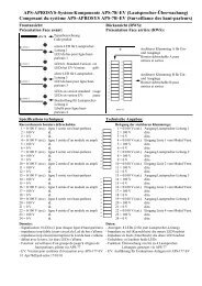
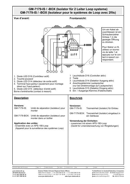
Vue d’avant:<br />
1. Diode LED D16 (Contrôleur actif)<br />
2. Touche-poussoir<br />
3. Diode LED D14 (détecteur de sortie actif)<br />
4. Terminal haut-parleur (seulement pour mont<strong>ag</strong>e<br />
direct sur l’haut-parleur)<br />
5. Diode LED D15 (détecteur d’entré actif)<br />
Borne d’entré/sortie (contact à ressort)<br />
Description<br />
Versions:<br />
<strong>GM</strong>-<strong>7179</strong>-<strong>IS</strong>: Unité de séparation (isolateur) pour<br />
monter<br />
<strong>GM</strong>-<strong>7179</strong>-<strong>BOX</strong>: Unité de séparation (isolateur) pour<br />
monter dans un boîtier<br />
Application des unités:<br />
- Ensemble avec un APS-180-<strong>Loop</strong><br />
(Appareil pour la surveillance des systèmes <strong>Loop</strong>)<br />
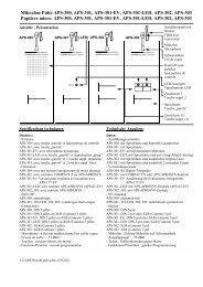
Frontansicht:<br />
1 2 3 4 5<br />
6<br />
1 Leuchtdiode D16 (Controller aktiv)<br />
2 Taste<br />
3 Leuchtdiode D14 (Detektor Ausgang aktiv)<br />
4 Anschlussklemme Lautsprecher<br />
(nur bei Direktmont<strong>ag</strong>e auf Lautsprecher)<br />
5 Leuchtdiode D15 (Detektor Eingang aktiv)<br />
6 Ein- / Ausgangs-Klemme (Federkontakt)<br />
Beschrieb<br />
Um ein Kabel abzuschliessen<br />
ist ein<br />
Schraubenzieher<br />
Grösse 1 in die<br />
gezeigte Öffnung<br />
zu drücken.<br />
Pour libérer un fil,<br />
utilisez un tournevis<br />
de taille 1 et<br />
appuyez sur le contact<br />
à ressort correspondant.<br />
Versionen:<br />
<strong>GM</strong>-<strong>7179</strong>-<strong>IS</strong>: Trenneinheit (<strong>Isolator</strong>) <strong>für</strong> Einbau<br />
<strong>GM</strong>-<strong>7179</strong>-<strong>BOX</strong>: Trenneinheit (<strong>Isolator</strong>) eingebaut in<br />
ein Gehäuse<br />
Verwendung der Einheiten:<br />
- zusammen mit einem APS-180-<strong>Loop</strong><br />
(Gerät <strong>für</strong> Linienüberwachung von Ringleitungen)<br />
Document: datasm_<strong>GM</strong>-<strong>7179</strong>_de.pub P<strong>ag</strong>e: 1 / 2 Created: 23.02.2012 By: mba/vo 1st Version: 01.00 Rev.: By: Version:
<strong>GM</strong>-<strong>7179</strong>-<strong>IS</strong> / -<strong>BOX</strong> (<strong>Isolator</strong> <strong>für</strong> 2 <strong>Leiter</strong> <strong>Loop</strong> systeme)<br />
<strong>GM</strong>-<strong>7179</strong>-<strong>IS</strong> / -<strong>BOX</strong> (Isolateur pour le systèmes de <strong>Loop</strong> avec 2fils)<br />
Spécifications techniques<br />
Raccordement de bornier à ressort débrochable (6):<br />
1 = 0 V Sortie<br />
2 = 100 V Sortie<br />
3 = 0 V Entré<br />
4 = 100 V Entré<br />
Raccordements du bornier à ressort débrochable (2):<br />
1 = 0 V Sortie pour haut-parleur<br />
2 = 100 V Sortie pour haut-parleur<br />
Données générales<br />
Poids:<br />
<strong>GM</strong>-<strong>7179</strong>-<strong>IS</strong>: 60 g<br />
<strong>GM</strong>-<strong>7179</strong>-<strong>BOX</strong>: 330 g<br />
Câble d‘installation pour le <strong>Loop</strong>: 2 x 1.5 mm²<br />
(Voir les instructions d‘installation APS-180-<strong>Loop</strong>)<br />
Puissance maximale par <strong>Loop</strong>: 250 W<br />
Puissance maximale par unité de séparation: 250 W<br />
Nombre maximal d‘unités de séparation par <strong>Loop</strong>: 35<br />
Courant consommé par signal de la porteuse:1.5 - 2.5 mA<br />
IMPORTANT:<br />
Toutes les unités d'un <strong>Loop</strong> doivent être connecter en série. La<br />
sortie d'une unité doit être connecté à l'entrée de la prochaine et<br />
avec la polarité correcte. L‘entré et la sortie peuvent être raccordés<br />
en manière échangée sans compromettre la fonction.<br />
Informations sur les unités de séparation <strong>GM</strong>-<strong>7179</strong>-<strong>IS</strong>:<br />
Pour le contrôle de fonction de l‘unité de séparation sert la touche 2<br />
et les diodes LED 1, 3 et 5. Dans le <strong>Loop</strong> actif sans erreur, tous les<br />
LED s‘allumés lorsque on appuy sur le touche. Les LED 3 et 5<br />
indiquent l‘état des détecteurs. Les LED correspondants s‘allument<br />
quand le signal de la porteuse est détecté par le circuit. En cas<br />
d‘une interruption, les deux LED sont allumés. Dans un cas de<br />
court-circuit isolé , la LED correspondante est inactive. La LED 1<br />
indique l‘état du contrôleur. Une LED lumineuse indique le contrôleur<br />
en service.<br />
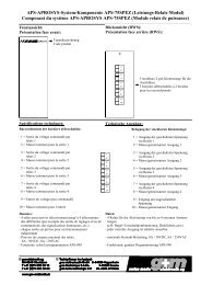
Hautparleur<br />
Entré Sortie<br />
Détecteur Logique Détecteur<br />
Mode de fonctionnement:<br />
Dans l‘état non alimenté, les deux relais sont ouverts. Dès que<br />
l‘isolateur détecte le signal de la porteuse, les deux relais se ferment.<br />
Lorsqu‘un court-circuit, le relais qui se trouve de côté de<br />
court-circuit se ouvre. Dans l‘état normal, l‘isolateur sera réinitialisé<br />
si le signal de la porteuse et interrompu au moins 1 seconde à<br />
l‘entré et la sortie.<br />
1 2 3 4<br />
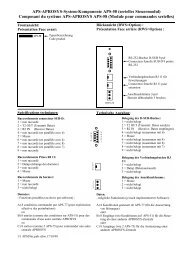
Technische Angaben<br />
Belegung der Federkontakt-Klemme (6):<br />
1 = 0 V Ausgang<br />
2 = 100 V Ausgang<br />
3 = 0 V Eingang<br />
4 = 100 V Eingang<br />
Belegung der Federkontakt-Klemme (2):<br />
1 = 0 V Ausgang auf Lautsprecher<br />
2 = 100 V Ausgang auf Lautsprecher<br />
Allgemeine Angaben<br />
Gewicht:<br />
<strong>GM</strong>-<strong>7179</strong>-<strong>IS</strong>: 60 g<br />
<strong>GM</strong>-<strong>7179</strong>-<strong>BOX</strong>: 330 g<br />
Installationskabel <strong>für</strong> die Ringleitungen: 2 x 1.5 mm²<br />
(Installationshinweise siehe APS-180-<strong>Loop</strong>)<br />
Maximale Leistung pro Ringleitung: 250 W<br />
Maximale Leistung pro Trenneinheit: 250 W<br />
Maximale Anzahl Trenneinheiten pro Ringleitung: 35<br />
Stromaufnahme Trägersignal: 1.5 - 2.5 mA<br />
WICHTIG:<br />
Alle Trenneinheiten eines <strong>Loop</strong>s müssen in Serie geschaltet sein.<br />
Der Ausgang einer Einheit ist jeweils mit dem Eingang der nächsten<br />
zu verbinden, wobei auf korrekte Polung geachtet werden muss.<br />
Der Eingang und Ausgang kann auch vertauscht angeschlossen<br />
werden ohne die Funktion zu beeinträchtigen.<br />
Informationen zu den Trenneinheiten <strong>GM</strong>-<strong>7179</strong>-<strong>IS</strong>:<br />
Zur Funktionskontrolle der Trenneinheit dient die Taste 2 und die<br />
Leuchtdioden 1, 3 und 5 Im aktiven fehlerfreien <strong>Loop</strong> leuchten beim<br />
Drücken der Taste alle LEDs. Die beiden LEDs 3 und 5 zeigen den<br />
Zustand der Detektoren. Detektiert die Schaltung das Trägersignal<br />
leuchtet die zugehörige LED. Bei einem Unterbruch leuchten beide<br />
LEDs, bei einem isolierten Kurzschluss ist jeweils eine LED inaktiv.<br />
Die dritte LED 1 zeigt den Zustand des Controllers an. Eine leuchtende<br />
LED zeigt an, dass der Controller in Betrieb ist.<br />
Document: datasm_<strong>GM</strong>-<strong>7179</strong>_de.pub P<strong>ag</strong>e: 2 / 2 Created: 23.02.2012 By: mba, vo 1st Version: 01.00 Rev.: By: Version:<br />
1 2<br />
Laut-<br />
sprecher<br />
Eingang Ausgang<br />
Detektor Logik Detektor<br />
Funktionsweise:<br />
In unversorgtem Zustand sind beide Relais geöffnet. Sobald der<br />
<strong>Isolator</strong> das Trägersignal detektiert, schliessen die beiden Relais.<br />
Bei einem Kurzschluss öffnet das Relais, welches auf der Seite des<br />
Kurzschlusses liegt. Der <strong>Isolator</strong> wird in den Normalzustand zurückgesetzt,<br />
wenn das Trägersignal länger als 1 Sekunde am Ein- und<br />
Ausgang unterbrochen wird.
Vista superior:<br />
Descripción<br />
<strong>GM</strong>-<strong>7179</strong>-<strong>IS</strong> / -<strong>BOX</strong> (<strong>Isolator</strong> unit for 2 wire loop systems)<br />
<strong>GM</strong>-<strong>7179</strong>-<strong>IS</strong> / -<strong>BOX</strong> (Aislador para sistemas de <strong>Loop</strong> a 2 hilos)<br />
1. Diodo LED D16 (Controlador activo)<br />
2. Pulsador de prueba<br />
3. Diodo LED D14 (detector de salida activo)<br />
4. Terminal altavoz (solo para montaje directo sobre<br />
el altavoz)<br />
5. Diodo LED D15 (detector de entrada activo)<br />
6. Terminal de entrada/salida (contactos de presión)<br />
Versiones:<br />
<strong>GM</strong>-<strong>7179</strong>-<strong>IS</strong>: Aislador para instalar en la red<br />
<strong>GM</strong>-<strong>7179</strong>-<strong>BOX</strong>: Aislador para montar en caja<br />
Aplicación:<br />
- Conjuntamente con un APS-180-<strong>Loop</strong><br />
(Unidad para la supervisión de los sistemas de lazo)<br />
Top view:<br />
1 2 3 4 5<br />
6<br />
1. Light emitting diode D16 (controller active)<br />
2. Push button<br />
3. Light emitting diode D14 (detector output active)<br />
4. Connection terminal for loudspeaker (only if<br />
mounted on loudspeaker)<br />
5. Light emitting diode D15 (detector input active)<br />
6. Connection terminal input / output (spring contact)<br />
Description<br />
Versions:<br />
<strong>GM</strong>-<strong>7179</strong>-<strong>IS</strong>: <strong>Isolator</strong> unit for built-in<br />
Para liberar un<br />
cable de conexión,<br />
utilizar un<br />
destornillador y<br />
pulse el terminal de<br />
presión<br />
correspondiente.<br />
To release a wire<br />
use a screw driver<br />
size 1 and press<br />
the corresponding<br />
spring contact.<br />
<strong>GM</strong>-<strong>7179</strong>-<strong>BOX</strong>: <strong>Isolator</strong> unit mounted in a box<br />
Use of the Units:<br />
- together with an APS-180-<strong>Loop</strong><br />
(device for line monitoring of loop systems)<br />
Document: datasm_<strong>GM</strong>-<strong>7179</strong>_de.pub P<strong>ag</strong>e: 3 / 2 Created: 01.12.2011 By: mba/ns 1st Version: 01.00 Rev.: By: Version:
<strong>GM</strong>-<strong>7179</strong>-<strong>IS</strong> / -<strong>BOX</strong> (<strong>Isolator</strong> unit for 2 wire loop systems)<br />
<strong>GM</strong>-<strong>7179</strong>-<strong>IS</strong> / -<strong>BOX</strong> (Aislador para sistemas de <strong>Loop</strong> a 2 hilos)<br />
Especificaciones técnicas<br />
Conexionado del terminal de presión (6):<br />
1 = 0 V Salida<br />
2 = 100 V Salida<br />
3 = 0 V Entrada<br />
4 = 100 V Entrada<br />
Conexionado del terminal de presión (4):<br />
1 = 0 V Salida para altavoz<br />
2 = 100 V Salida para altavoz<br />
Datos generales<br />
Peso:<br />
<strong>GM</strong>-<strong>7179</strong>-<strong>IS</strong>: 60 g<br />
<strong>GM</strong>-<strong>7179</strong>-<strong>BOX</strong>: 330 g<br />
Cable para instalación del Lazo: 2 x 1.5 mm²<br />
(Ver instrucciones de instalación APS-180-<strong>Loop</strong>)<br />
Potencia máxima por lazo: 250 W<br />
Potencia máxima por aislador : 250 W<br />
Número máximo de aisladores por lazo: 35<br />
Consumo de corriente de la señal portadora : 1.5 - 2.5 mA<br />
IMPORTANTE:<br />
Todas los aisladores de un lazo deben ser conectados en serie. La<br />
salida de un aislador debe ser conectada a la entrada del siguiente<br />
y con la polaridad correcta. La entrada y la salida pueden ser<br />
intercambiadas sin comprometer el funcionamiento.<br />
Información para el manejo de los aisladores <strong>GM</strong>-<strong>7179</strong>-<strong>IS</strong>:<br />
Al pulsar el botón 2 los LED 1, 3 y 5 indican el estado del aislador.<br />
Cuando el lazo está activo y sin errores, los 3 LED se iluminan<br />
cuando su pulsa el botón. Los LED 3 y 5 indican el estado de los<br />
detectores. Los LED se iluminan cuando la señal de la portadora es<br />
detectada por el circuito. En caso de una interrupción en la línea los<br />
dos LED se iluminan. En caso de cortocircuito, el LED del lado del<br />
cortocircuito se ap<strong>ag</strong>a. El LED 1 indica el estado del controlador,<br />
cuando está encendido indica que el aislador está funcionando.<br />
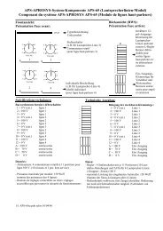
Altavoz<br />
Entrada Salida<br />
Detector Lógica Detector<br />
Modo de funcionamiento :<br />
En estado de reposo (sin señal portadora), los dos relés están<br />
abiertos. Cuando el aislador detecta la señal de la portadora, los<br />
dos relés se cierran. Cuando hay un cortocircuito, el relé del lado<br />
del cortocircuito se abre. En estado normal, el aislador se<br />
reajustará de nuevo si la señal de la portadora se ap<strong>ag</strong>a al menos<br />
un segundo.<br />
1 2 3 4<br />
Technical Specifications<br />
Connection di<strong>ag</strong>ram of terminals (6):<br />
1 = 0 V Output<br />
2 = 100 V Output<br />
3 = 0 V Output<br />
4 = 100 V Output<br />
Connection di<strong>ag</strong>ram of terminal (2):<br />
1 = 0 V output for loudspeaker<br />
2 = 100 V output for loudspeaker<br />
General information<br />
Weight:<br />
<strong>GM</strong>-<strong>7179</strong>-<strong>IS</strong>: 60 g<br />
<strong>GM</strong>-<strong>7179</strong>-<strong>BOX</strong>: 330 g<br />
Cable for <strong>Loop</strong> installation: 2 x 1.5 mm²<br />
(instructions for installation please refer to APS-180-<strong>Loop</strong>)<br />
Maximum power for one <strong>Loop</strong>: 250 W<br />
Maximum power for one isolator: 250 W<br />
Maximum number of isolators for each loop: 35<br />
current consumption isolator: 1.5 - 2.5 mA<br />
IMPORTANT:<br />
All isolators have to be connected in a daisy chain.<br />
The output of one isolator has to be connected to the input of the<br />
next isolator. the <strong>Isolator</strong>s have to be connected with correct polarity.<br />
input and output could be switched without any problems.<br />
Information for handling the isolators <strong>GM</strong>-<strong>7179</strong>-<strong>IS</strong>:<br />
By pressing the button 2 the LEDs 1, 3 and 5 are indicating the<br />
status of the isolator. If the Status is ok, all 3 LEDs are on. The LED<br />
3 and 5 are indicating the status of the detectors. If the carrier signal<br />
is detected the related LED is on. In case of an interruption of the<br />
line all LEDs are on.<br />
In case of a short circuit the LED on the Short circuit side is off.<br />
The LED 1 is indicating that the isolator is running.<br />
Document: datasm_<strong>GM</strong>-<strong>7179</strong>_de.pub P<strong>ag</strong>e: 4 / 2 Created: 01.12.2011 By: mba 1st Version: 01.00 Rev.: By: Version:<br />
1 2<br />
Loud<br />
speaker<br />
Input Output<br />
Detector Logic Detector<br />
Mode of operation:<br />
In idle state (without a carrier signal) both relais are open.<br />
When the isolator detects a carrier signal it is powering up the isolator<br />
and it tries to close the relais. In case of a short circuit the relais<br />
near the short circuit is opening and remains in short circuit state.<br />
The isolator can be set back if the carrier signal is off at least one<br />
second.