3 Other operating modes of the G-18.mft - NRI
3 Other operating modes of the G-18.mft - NRI
3 Other operating modes of the G-18.mft - NRI

You also want an ePaper? Increase the reach of your titles
YUMPU automatically turns print PDFs into web optimized ePapers that Google loves.
DESIGN G-<strong>18.mft</strong> with vending machine control system<br />
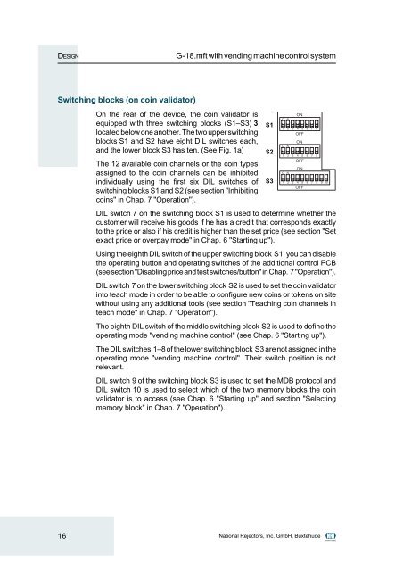
Switching blocks (on coin validator)<br />
On <strong>the</strong> rear <strong>of</strong> <strong>the</strong> device, <strong>the</strong> coin validator is<br />
equipped with three switching blocks (S1–S3) 3<br />
located below one ano<strong>the</strong>r. The two upper switching<br />
blocks S1 and S2 have eight DIL switches each,<br />
and <strong>the</strong> lower block S3 has ten. (See Fig. 1a)<br />
The 12 available coin channels or <strong>the</strong> coin types<br />
assigned to <strong>the</strong> coin channels can be inhibited<br />
individually using <strong>the</strong> first six DIL switches <strong>of</strong><br />
switching blocks S1 and S2 (see section "Inhibiting<br />
coins" in Chap. 7 "Operation").<br />
DIL switch 7 on <strong>the</strong> switching block S1 is used to determine whe<strong>the</strong>r <strong>the</strong><br />
customer will receive his goods if he has a credit that corresponds exactly<br />
to <strong>the</strong> price or also if his credit is higher than <strong>the</strong> set price (see section "Set<br />
exact price or overpay mode" in Chap. 6 "Starting up").<br />
Using <strong>the</strong> eighth DIL switch <strong>of</strong> <strong>the</strong> upper switching block S1, you can disable<br />
<strong>the</strong> <strong>operating</strong> button and <strong>operating</strong> switches <strong>of</strong> <strong>the</strong> additional control PCB<br />
(see section "Disabling price and test switches/button" in Chap. 7 "Operation").<br />
DIL switch 7 on <strong>the</strong> lower switching block S2 is used to set <strong>the</strong> coin validator<br />
into teach mode in order to be able to configure new coins or tokens on site<br />
without using any additional tools (see section "Teaching coin channels in<br />
teach mode" in Chap. 7 "Operation").<br />
The eighth DIL switch <strong>of</strong> <strong>the</strong> middle switching block S2 is used to define <strong>the</strong><br />
<strong>operating</strong> mode "vending machine control" (see Chap. 6 "Starting up").<br />
The DIL switches 1–8 <strong>of</strong> <strong>the</strong> lower switching block S3 are not assigned in <strong>the</strong><br />
<strong>operating</strong> mode "vending machine control". Their switch position is not<br />
relevant.<br />
DIL switch 9 <strong>of</strong> <strong>the</strong> switching block S3 is used to set <strong>the</strong> MDB protocol and<br />
DIL switch 10 is used to select which <strong>of</strong> <strong>the</strong> two memory blocks <strong>the</strong> coin<br />
validator is to access (see Chap. 6 "Starting up" and section "Selecting<br />
memory block" in Chap. 7 "Operation").<br />
16 National Rejectors, Inc. GmbH, Buxtehude<br />
S1<br />
S2<br />
S3