Kuhnke Electronics Instruction Manual
Kuhnke Electronics Instruction Manual
Kuhnke Electronics Instruction Manual

Create successful ePaper yourself
Turn your PDF publications into a flip-book with our unique Google optimized e-Paper software.
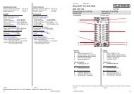
5.3.3 Functions of Internal Outputs (0.1 A)<br />
SO_0...SO_3<br />
The following functions are supported<br />
� normal output<br />
5.3.3.1 Normal Outputs<br />
� clock pulse output<br />
5.3.3.2 Clock Pulse Outputs<br />
'Normal' output means that the output is enabled or<br />
disabled as a continuous signal.<br />
Software<br />
'Clock pulse' output means that a clock pulse is enabled<br />
or disabled as the output signal.<br />
Clock pulse outputs are designed for the actuation or<br />
stepper motor output stages, for example.<br />
- The pulse-to-pause ratio of the clock pulse is always<br />
1:1.<br />
To start or stop a motor, the speed needs to go up or<br />
down with reference to the time, which is realised by the<br />
PLC program selecting the appropriate frequency.<br />
� The value entered and the frequency are linked by an<br />
allocation table which is stored in the PLC's monitor<br />
program.<br />
� The frequency is adjustable by selecting any of the<br />
395 different frequencies on the list.<br />
� Note that selecting '0' sets a frequency of 200 Hz<br />
already.<br />
� Whereas do0 and do1 as well as do2 and do3 are<br />
actuated by the same clock pulse, they can still be<br />
enabled and disabled separately.<br />
Select input/output function (� 5.3.1.1)<br />
The frequency is set by variables.<br />
� To be shown information about these variables,<br />
choose "Resources, PLC Configuration, <strong>Kuhnke</strong><br />
133