- Page 1 and 2:
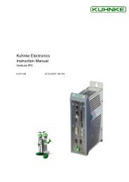
Kuhnke Electronics Instruction Manu
- Page 3 and 4:
Table of Contents Introduction 1 In
- Page 5 and 6:
Introduction 4.3.4 PLC Configuratio
- Page 7 and 8:
Introduction 6.1.4 Station Address
- Page 9 and 10:
1 Introduction Introduction Ventura
- Page 11 and 12:
1.2 Variants Introduction Compact c
- Page 13 and 14:
Advantages of Decentralisation Intr
- Page 15 and 16:
1.5 Network Examples 1.5.1 PROFIBUS
- Page 17 and 18:
2 Reliability, Safety 2.1 Intended
- Page 19 and 20:
2.4.3 Note Reliability, Safety This
- Page 21 and 22:
2.5.1 Project Planning and Installa
- Page 23 and 24:
2.6 Electromagnetic Compatibility 2
- Page 25 and 26:
2.6.6.2 Contamination Reliability,
- Page 27 and 28:
3 Hardware 3.1 System Description H
- Page 29 and 30:
Hardware Extensions Ventura Remote
- Page 31 and 32:
3.3 Power Supply 3.3.1 Earth left s
- Page 33 and 34:
3.3.3 Power Supply Hardware Voltage
- Page 35 and 36:
3.4 Inputs and Outputs 3.4.1 Digita
- Page 37 and 38:
3.4.2 Digital Combi I/Os Hardware V
- Page 39 and 40:
3.4.3 Analogue Inputs Hardware Vent
- Page 41 and 42:
3.5 A, B, Ref Counter Hardware Vent
- Page 43 and 44:
3.6.2 PROFIBUS Hardware Ventura Rem
- Page 45 and 46:
3.7 Expansion Modules Ventura Remot
- Page 47 and 48:
3.8.2 Mode Selector mode selector H
- Page 49 and 50:
3.8.3.1 RUN 3.8.3.2 Stop 3.8.3.3 Ex
- Page 51 and 52:
3.9 Status and Failure Indication "
- Page 53 and 54:
Installation 4 PLC Functions of Ven
- Page 55 and 56:
4.2 Writing CoDeSys Programs Online
- Page 57 and 58:
4.2.2 CAN: Online CAN Function Libr
- Page 59 and 60:
4.3.1 Operating System Function Lib
- Page 61 and 62:
4.3.3 Task Configuration 4.3.3.1 PL
- Page 63 and 64:
4.3.3.2 The Task Configurator 4.3.3
- Page 65 and 66:
4.3.4 PLC Configuration Function Li
- Page 67 and 68:
Function Libraries DI16/DO16". Repe
- Page 69 and 70:
4.3.6 The Flash File System Functio
- Page 71 and 72:
4.4.1 Installing a Thread Function
- Page 73 and 74:
Thread usage Function Libraries A t
- Page 75 and 76:
4.4.2 Installing / Uninstalling a T
- Page 77 and 78: To uninstall a timer task: Function
- Page 79 and 80: 4.4.3 Enabling / Disabling the Outp
- Page 81 and 82: 4.4.5 Direct Write of Local Outputs
- Page 83 and 84: FUNCTION INSTALL_ERROR_IRQ : BOOL V
- Page 85 and 86: Function Libraries INSTALL_INPUT_IR
- Page 87 and 88: 4.4.8 Installing a REF IRQ Module F
- Page 89 and 90: 4.4.10 Setting up the Watchdog Func
- Page 91 and 92: 4.5 Library MMC.LIB Function Librar
- Page 93 and 94: 4.5.2 Registering with the File Sys
- Page 95 and 96: 4.5.4 Copying Files Function Librar
- Page 97 and 98: 4.5.6 Determining the Free MMC Spac
- Page 99 and 100: 4.5.8 Moving a File Function Librar
- Page 101 and 102: 4.5.9 Opening a File Function Libra
- Page 103 and 104: 4.5.10 Reading from a File Function
- Page 105 and 106: 4.5.12 Setting the Edit Bookmark of
- Page 107 and 108: 4.5.14 Initialising the File System
- Page 109 and 110: Function Libraries FUNCTION_BLOCK M
- Page 111 and 112: � Use 'start' to repeatedly run t
- Page 113 and 114: 4.6.4 Online Reset (cold) 4.6.5 Res
- Page 115 and 116: 4.7.2 Variables with Set Addresses
- Page 117 and 118: 4.8 Extraremanent Data 4.8.1 Remane
- Page 119 and 120: Remanent Data If an extraremanent m
- Page 121 and 122: TYPE Extrarema_02: STRUCT END_STRUC
- Page 123 and 124: Start_OK := CheckXREMDATA(Clear); I
- Page 125 and 126: 5 Software Software Read this secti
- Page 127: Internal combi I/Os %IX0.0-%IX0.3 a
- Page 131 and 132: Software If an "Input IRQ module" h
- Page 133 and 134: 5.3.3 Functions of Internal Outputs
- Page 135 and 136: Software Value Frequency Value Freq
- Page 137 and 138: 5.3.4 Short-circuited Output Softwa
- Page 139 and 140: 5.3.5 Internal Analogue Input Funct
- Page 141 and 142: 5.3.6 Internal Analogue Output Func
- Page 143 and 144: 5.3.7 Functions of Internal Counter
- Page 145 and 146: 5.3.7.1.2 Event Counter Variables V
- Page 147 and 148: Resolution of the rotary encoder: s
- Page 149 and 150: Software 5.4 Functions of the Basic
- Page 151 and 152: 5.7 Status Messages of Expansion Mo
- Page 153 and 154: 6 PROFIBUS-DP 6.1 Basic Information
- Page 155 and 156: 6.2 Master-Slave Communication PROF
- Page 157 and 158: 6.2.2 Receive Parameter Data (Prm_D
- Page 159 and 160: 6.2.2.2 Device-specific Bus Paramet
- Page 161 and 162: PROFIBUS replaces the term "byte" w
- Page 163 and 164: Octet 4: Diag.Master_Add PROFIBUS A
- Page 165 and 166: 6.2.4 Master-Slave Data Communicati
- Page 167 and 168: Example: VAR bIn_0: BYTE; bOut_0: B
- Page 169 and 170: 7 CANopen CANopen At this point, we
- Page 171 and 172: 7.1.1 CANopen Example CANopen A Ven
- Page 173 and 174: • Step3: Write and test CoDeSys p
- Page 175 and 176: PROGRAM PLC_PRG VAR CANMaster_Ok: B
- Page 177 and 178: 8 PLC Error Handling 8.1 "Failure"
- Page 179 and 180:
Example VAR C690_Error: BYTE; END_V
- Page 181 and 182:
8.3.1 Short-circuited Output (Error
- Page 183 and 184:
=> - STOP: The program is stopped E
- Page 185 and 186:
9 Appendix 9.1 Technical Data 9.1.1
- Page 187 and 188:
Appendix Max. current .............
- Page 189 and 190:
9.1.3 Communication Ports V.24 port
- Page 191 and 192:
9.2 Order Specifications 9.2.1 Cont
- Page 193 and 194:
Appendix 9.3 Ventura Remote I/O Exp
- Page 195 and 196:
9.5 Sales & Service Appendix Please
- Page 197 and 198:
9.6 Index A, B, Ref counter 146 con
- Page 199:
PROFIBUS port 43 PROFIBUS-DP 153 di


