Kuhnke Electronics Instruction Manual
Kuhnke Electronics Instruction Manual
Kuhnke Electronics Instruction Manual

Create successful ePaper yourself
Turn your PDF publications into a flip-book with our unique Google optimized e-Paper software.
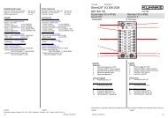
Internal combi I/Os %IX0.0-%IX0.3 and<br />
%QX0.0-%QX0.3<br />
Software<br />
The basic unit hosts a set of some I/Os which can be<br />
assigned both normal and special functions.<br />
� Inputs "read" the signals of switches, push-buttons,<br />
initiators, etc. The generate interrupts and run the<br />
input IRQ modules. The signal state is entered into<br />
the process image.<br />
Run function FLUSH_INPUTS to directly get the<br />
signal states of internal inputs and of the inputs of the<br />
basic module.<br />
� Outputs deliver control signals to relays, contactors,<br />
solenoids, etc. in order to turn them on or off. The<br />
CPU enters the signals into the process image<br />
depending on user program instructions. The output<br />
data in the process image are sent to the outputs<br />
between every two PLC cycles. Run function<br />
FLUSH_OUTPUTS to directly get the signal states of<br />
internal outputs and of the outputs of the basic<br />
module.<br />
If set up accordingly, the internal outputs can also be<br />
used as clock pulse outputs for actuating stepper<br />
motors compliant to a frequency table stored in the<br />
PLC memory. The PLC program selects the correct<br />
values from the table, maintaining a pulse-to-pause<br />
ratio of 1:1 at all times. Whereas outputs do0 and do1<br />
as well as do2 and do3 are actuated by the same<br />
clock pulse, they can still be enabled and disabled<br />
separately.<br />
127