Fuxx Control - ARS 2320 / ARS 2340 Instruction Manual - Kuhnke
Fuxx Control - ARS 2320 / ARS 2340 Instruction Manual - Kuhnke Fuxx Control - ARS 2320 / ARS 2340 Instruction Manual - Kuhnke
Fuxx Control ARS 2320 / ARS 2340 KUHNKE Automation 8.7.4 Cable type and configuration [X1] The cable names given refer to cables made by Lapp. They have proven to be reliable and are successfully used in many applications. However, it is also possible to use comparable cables from other manufacturers, e.g. Lütze or Helukabel. � LAPP KABEL UNITRONIC-LiYCY; 25 x 0.25 mm² Figure 24 shows the cable between the ARS 2300 servo positioning controller and the control system. The cable shown has two cable shields. The outer cable shield is connected to PE on both sides. Inside the ARS 2300 servo positioning controller, the connector housing of the D-Sub connector is connected to PE. If metal D-Sub connector housings are used, the cable shield is simply squeezed underneath the strain relief. Often an unshielded cable is sufficient for 24V signals. In environments with high interferences or in the case of long cables (l > 2m) between the control system and the ARS 2300 servo positioning controller, Kuhnke recommends using shielded control cables. Although the analog inputs of the ARS 2300 servo positioning controller are differential, using unshielded cables for the analog signals is not recommended as interferences, e.g. caused by switching contacts, or output stage interferences of the converters can reach high amplitudes. They couple themselves into the analog signals and cause common-mode interferences which may lead to deviations of the analog measured values. In the case of limited cable lengths (l < 2m, wiring inside the control cabinet), the outer dual-sided PE shield is enough to guarantee trouble-free operation. For optimal interference suppression of the analog signals, the cores for the analog signals have to be shielded together and separated from other cores. At the ARS 2300 servo positioning controller, the inner cable shield is connected on one side to AGND (pin 1 or 14). It can be connected on both sides in order to establish a connection between the reference potentials of the control system and the ARS 2300 servo positioning controller. Pins 1 and 14 are directly connected to each other inside the controller. 8.7.5 Connection notes [X1] The digital inputs are rated for control voltages of 24V. The high signal level already ensures a high level of interference immunity of these inputs. The ARS 2300 servo positioning controller provides an auxiliary voltage of 24V which may be loaded with 100 mA maximum. As a result, the inputs can be activated directly via switches. Activation via the 24V outputs of a PLC is of course also possible. The digital outputs are so-called "high-side switches". This means that the 24V of the ARS 2300 servo positioning controller are actively switched through to the output. Loads such as lamps, relays, etc. are thus switched from the output to GND24. The four outputs DOUT0 to DOUT3 can be loaded with a maximum of 100mA each. The outputs can also be led directly to 24V inputs of a PLC. 94 E 732 GB 14.12.2006
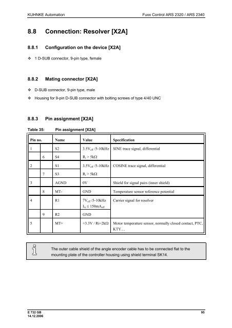
KUHNKE Automation Fuxx Control ARS 2320 / ARS 2340 8.8 Connection: Resolver [X2A] 8.8.1 Configuration on the device [X2A] � 1 D-SUB connector, 9-pin type, female 8.8.2 Mating connector [X2A] � D-SUB connector, 9-pin type, male � Housing for 9-pin D-SUB connector with bolting screws of type 4/40 UNC 8.8.3 Pin assignment [X2A] Table 35: Pin assignment [X2A] Pin no. Name Value Specification 1 S2 6 S4 2 S1 7 S3 3.5Veff /5-10kHz Ri > 5kΩ 3.5Veff /5-10kHz Ri > 5kΩ SINE trace signal, differential COSINE trace signal, differential 3 AGND 0V Shield for signal pairs (inner shield) 8 MT- GND Temperature sensor reference potential 4 R1 7Veff /5-10kHz 9 R2 GND IA ≤ 150mAeff Carrier signal for resolver 5 MT+ +3.3V / Ri=2kΩ Motor temperature sensor, normally closed contact, PTC, KTY… The outer cable shield of the angle encoder cable has to be connected flat to the mounting plate of the controller housing using shield terminal SK14. E 732 GB 95 14.12.2006
- Page 43 and 44: KUHNKE Automation Fuxx Control ARS
- Page 45 and 46: KUHNKE Automation Fuxx Control ARS
- Page 47 and 48: KUHNKE Automation Fuxx Control ARS
- Page 49 and 50: KUHNKE Automation Fuxx Control ARS
- Page 51 and 52: KUHNKE Automation Fuxx Control ARS
- Page 53 and 54: KUHNKE Automation Fuxx Control ARS
- Page 55 and 56: KUHNKE Automation Fuxx Control ARS
- Page 57 and 58: KUHNKE Automation Fuxx Control ARS
- Page 59 and 60: KUHNKE Automation Fuxx Control ARS
- Page 61 and 62: KUHNKE Automation Fuxx Control ARS
- Page 63 and 64: KUHNKE Automation Fuxx Control ARS
- Page 65 and 66: KUHNKE Automation Fuxx Control ARS
- Page 67 and 68: KUHNKE Automation Fuxx Control ARS
- Page 69 and 70: KUHNKE Automation Fuxx Control ARS
- Page 71 and 72: KUHNKE Automation Fuxx Control ARS
- Page 73 and 74: KUHNKE Automation Fuxx Control ARS
- Page 75 and 76: KUHNKE Automation Fuxx Control ARS
- Page 77 and 78: KUHNKE Automation Fuxx Control ARS
- Page 79 and 80: KUHNKE Automation Fuxx Control ARS
- Page 81 and 82: KUHNKE Automation Fuxx Control ARS
- Page 83 and 84: KUHNKE Automation Fuxx Control ARS
- Page 85 and 86: KUHNKE Automation Fuxx Control ARS
- Page 87 and 88: KUHNKE Automation Fuxx Control ARS
- Page 89 and 90: KUHNKE Automation Fuxx Control ARS
- Page 91 and 92: KUHNKE Automation Fuxx Control ARS
- Page 93: KUHNKE Automation Fuxx Control ARS
- Page 97 and 98: KUHNKE Automation Fuxx Control ARS
- Page 99 and 100: KUHNKE Automation Fuxx Control ARS
- Page 101 and 102: KUHNKE Automation Fuxx Control ARS
- Page 103 and 104: KUHNKE Automation Fuxx Control ARS
- Page 105 and 106: KUHNKE Automation Fuxx Control ARS
- Page 107 and 108: KUHNKE Automation Fuxx Control ARS
- Page 109 and 110: KUHNKE Automation Fuxx Control ARS
- Page 111 and 112: KUHNKE Automation Fuxx Control ARS
- Page 113 and 114: KUHNKE Automation Fuxx Control ARS
- Page 115 and 116: KUHNKE Automation Fuxx Control ARS
- Page 117 and 118: KUHNKE Automation Fuxx Control ARS
- Page 119 and 120: KUHNKE Automation Fuxx Control ARS
- Page 121 and 122: KUHNKE Automation Fuxx Control ARS
- Page 123 and 124: KUHNKE Automation Fuxx Control ARS
- Page 125 and 126: KUHNKE Automation Fuxx Control ARS
- Page 127 and 128: KUHNKE Automation Fuxx Control ARS
- Page 129 and 130: KUHNKE Automation Fuxx Control ARS
- Page 131 and 132: KUHNKE Automation Fuxx Control ARS
- Page 133 and 134: KUHNKE Automation Fuxx Control ARS
- Page 135 and 136: KUHNKE Automation Fuxx Control ARS
- Page 137 and 138: KUHNKE Automation Fuxx Control ARS
- Page 139 and 140: KUHNKE Automation Fuxx Control ARS
- Page 141 and 142: KUHNKE Automation Fuxx Control ARS
- Page 143 and 144: KUHNKE Automation Fuxx Control ARS
KUHNKE Automation <strong>Fuxx</strong> <strong>Control</strong> <strong>ARS</strong> <strong>2320</strong> / <strong>ARS</strong> <strong>2340</strong><br />
8.8 Connection: Resolver [X2A]<br />
8.8.1 Configuration on the device [X2A]<br />
� 1 D-SUB connector, 9-pin type, female<br />
8.8.2 Mating connector [X2A]<br />
� D-SUB connector, 9-pin type, male<br />
� Housing for 9-pin D-SUB connector with bolting screws of type 4/40 UNC<br />
8.8.3 Pin assignment [X2A]<br />
Table 35: Pin assignment [X2A]<br />
Pin no. Name Value Specification<br />
1 S2<br />
6 S4<br />
2 S1<br />
7 S3<br />
3.5Veff /5-10kHz<br />
Ri > 5kΩ<br />
3.5Veff /5-10kHz<br />
Ri > 5kΩ<br />
SINE trace signal, differential<br />
COSINE trace signal, differential<br />
3 AGND 0V Shield for signal pairs (inner shield)<br />
8 MT- GND Temperature sensor reference potential<br />
4 R1 7Veff /5-10kHz<br />
9 R2 GND<br />
IA ≤ 150mAeff<br />
Carrier signal for resolver<br />
5 MT+ +3.3V / Ri=2kΩ Motor temperature sensor, normally closed contact, PTC,<br />
KTY…<br />
The outer cable shield of the angle encoder cable has to be connected flat to the<br />
mounting plate of the controller housing using shield terminal SK14.<br />
E 732 GB 95<br />
14.12.2006


