Fuxx Control - ARS 2320 / ARS 2340 Instruction Manual - Kuhnke
Fuxx Control - ARS 2320 / ARS 2340 Instruction Manual - Kuhnke Fuxx Control - ARS 2320 / ARS 2340 Instruction Manual - Kuhnke
Fuxx Control ARS 2320 / ARS 2340 KUHNKE Automation 7.2 Device view L1: 400VAC mains phase connection L2: 400VAC mains phase connection L3: 400VAC mains phase connection PE: Mains ground conductor connection ZK+: Positive DC-link voltage ZK-: Negative DC-link voltage ext. Br-R: Connection of the external braking resistor int. Br.-R: Connection of the internal braking resistor U: Motor phase 1 connection V: Motor phase 2 connection W: Motor phase 3 connection PE: Mains ground conductor connection MT+: Motor temperature sensor MT-: Motor temperature sensor PE: Motor temperature sensor shield PE: Motor holding brake BR+: Motor holding brake BR-: Motor-Haltebremse Connection for the outer shield of the motor cable (motor shield terminal) Mounting plate [X9] L1 L2 L3 PE ZK+ ZK+ ZK- ZK- CAUTION! [X6] U V W PE [X6A] MT+ MT- PE PE BR+ BR- COOPERTools BR-EXT BR-CH BR-INT Risk of Electric Shock! Do not Touch Electrical Connectors for 5 Minutes after Switching Power off! Read Manual before Installing! High Leakage Current! First connect to Earth! ARS 2320 The technology slots TECH1 and TECH2 are located at the top Status display [X5]: Serial interface RS232 [X4]: CAN-Bus 70 E 732 GB 14.12.2006 RESET READY CAN ON STATE [X5] RS232/ COM [X1] I/O [X10] IN [X11] OUT [X4] CAN Figure 10: Servo positioning controller ARS 2320: Front view RESET button READY-LED CAN-LED [X1]: I/O communication [X10]: Incremental encoder input [X11]: Incremental encoder output
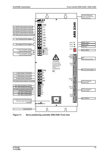
KUHNKE Automation Fuxx Control ARS 2320 / ARS 2340 L1: 400VAC mains phase connection L2: 400VAC mains phase connection L3: 400VAC mains phase connection PE: Mains ground conductor connection ZK+: Positive DC-link voltage ZK-: Negative DC-link voltage ext. Br-R: Connection of the external braking resistor int. Br.-R: Connection of the internal braking resistor U: Motor phase 1 connection V: Motor phase 2 connection W: Motor phase 3 connection PE: Motor ground conductor connection MT+: Motor temperature sensor MT-: Motor temperature sensor PE: Motor temperature sensor shield PE: Motor holding brake BR+: Motor holding brake BR-: Motor holding brake Connection for the outer shield of the motor cable (motor shield terminal) Mounting plate [X9] L1 L2 L3 PE ZK+ ZK+ ZK- ZK- [X6] U V W PE [X6A] MT+ MT- PE PE BR+ BR- [X9A] COOPERTools BR-EXT BR-CH BR-INT CAUTION! Risk of Electric Shock! Do not Touch Electrical Connectors for 5 Minutes after Switching Power off! Read Manual before Installing! High Leakage Current! First connect to Earth! Figure 11: Servo positioning controller ARS 2340: Front view [X5] RS232/ COM The technology slots TECH1 and TECH2 are located at the top Status display [X5]: Serial interface RS232 [X4]: CAN-Bus E 732 GB 71 14.12.2006 RESET READY CAN ON STATE [X1] I/O [X10] IN [X11] OUT [X4] CAN ARS 2340 RESET button READY-LED CAN-LED [X1]: I/O communication [X10]: Incremental encoder input [X11]: Incremental encoder output
- Page 19 and 20: KUHNKE Automation Fuxx Control ARS
- Page 21 and 22: KUHNKE Automation Fuxx Control ARS
- Page 23 and 24: KUHNKE Automation Fuxx Control ARS
- Page 25 and 26: KUHNKE Automation Fuxx Control ARS
- Page 27 and 28: KUHNKE Automation Fuxx Control ARS
- Page 29 and 30: KUHNKE Automation Fuxx Control ARS
- Page 31 and 32: KUHNKE Automation Fuxx Control ARS
- Page 33 and 34: KUHNKE Automation Fuxx Control ARS
- Page 35 and 36: KUHNKE Automation Fuxx Control ARS
- Page 37 and 38: KUHNKE Automation Fuxx Control ARS
- Page 39 and 40: KUHNKE Automation Fuxx Control ARS
- Page 41 and 42: KUHNKE Automation Fuxx Control ARS
- Page 43 and 44: KUHNKE Automation Fuxx Control ARS
- Page 45 and 46: KUHNKE Automation Fuxx Control ARS
- Page 47 and 48: KUHNKE Automation Fuxx Control ARS
- Page 49 and 50: KUHNKE Automation Fuxx Control ARS
- Page 51 and 52: KUHNKE Automation Fuxx Control ARS
- Page 53 and 54: KUHNKE Automation Fuxx Control ARS
- Page 55 and 56: KUHNKE Automation Fuxx Control ARS
- Page 57 and 58: KUHNKE Automation Fuxx Control ARS
- Page 59 and 60: KUHNKE Automation Fuxx Control ARS
- Page 61 and 62: KUHNKE Automation Fuxx Control ARS
- Page 63 and 64: KUHNKE Automation Fuxx Control ARS
- Page 65 and 66: KUHNKE Automation Fuxx Control ARS
- Page 67 and 68: KUHNKE Automation Fuxx Control ARS
- Page 69: KUHNKE Automation Fuxx Control ARS
- Page 73 and 74: KUHNKE Automation Fuxx Control ARS
- Page 75 and 76: KUHNKE Automation Fuxx Control ARS
- Page 77 and 78: KUHNKE Automation Fuxx Control ARS
- Page 79 and 80: KUHNKE Automation Fuxx Control ARS
- Page 81 and 82: KUHNKE Automation Fuxx Control ARS
- Page 83 and 84: KUHNKE Automation Fuxx Control ARS
- Page 85 and 86: KUHNKE Automation Fuxx Control ARS
- Page 87 and 88: KUHNKE Automation Fuxx Control ARS
- Page 89 and 90: KUHNKE Automation Fuxx Control ARS
- Page 91 and 92: KUHNKE Automation Fuxx Control ARS
- Page 93 and 94: KUHNKE Automation Fuxx Control ARS
- Page 95 and 96: KUHNKE Automation Fuxx Control ARS
- Page 97 and 98: KUHNKE Automation Fuxx Control ARS
- Page 99 and 100: KUHNKE Automation Fuxx Control ARS
- Page 101 and 102: KUHNKE Automation Fuxx Control ARS
- Page 103 and 104: KUHNKE Automation Fuxx Control ARS
- Page 105 and 106: KUHNKE Automation Fuxx Control ARS
- Page 107 and 108: KUHNKE Automation Fuxx Control ARS
- Page 109 and 110: KUHNKE Automation Fuxx Control ARS
- Page 111 and 112: KUHNKE Automation Fuxx Control ARS
- Page 113 and 114: KUHNKE Automation Fuxx Control ARS
- Page 115 and 116: KUHNKE Automation Fuxx Control ARS
- Page 117 and 118: KUHNKE Automation Fuxx Control ARS
- Page 119 and 120: KUHNKE Automation Fuxx Control ARS
KUHNKE Automation <strong>Fuxx</strong> <strong>Control</strong> <strong>ARS</strong> <strong>2320</strong> / <strong>ARS</strong> <strong>2340</strong><br />
L1: 400VAC mains phase connection<br />
L2: 400VAC mains phase connection<br />
L3: 400VAC mains phase connection<br />
PE: Mains ground conductor connection<br />
ZK+: Positive DC-link voltage<br />
ZK-: Negative DC-link voltage<br />
ext. Br-R: Connection of the<br />
external braking resistor<br />
int. Br.-R: Connection of the<br />
internal braking resistor<br />
U: Motor phase 1 connection<br />
V: Motor phase 2 connection<br />
W: Motor phase 3 connection<br />
PE: Motor ground conductor connection<br />
MT+: Motor temperature sensor<br />
MT-: Motor temperature sensor<br />
PE: Motor temperature sensor shield<br />
PE: Motor holding brake<br />
BR+: Motor holding brake<br />
BR-: Motor holding brake<br />
Connection for the outer shield of<br />
the motor cable (motor shield<br />
terminal)<br />
Mounting plate<br />
[X9]<br />
L1<br />
L2<br />
L3<br />
PE<br />
ZK+<br />
ZK+<br />
ZK-<br />
ZK-<br />
[X6]<br />
U<br />
V<br />
W<br />
PE<br />
[X6A]<br />
MT+<br />
MT-<br />
PE<br />
PE<br />
BR+<br />
BR-<br />
[X9A]<br />
COOPERTools<br />
BR-EXT<br />
BR-CH<br />
BR-INT<br />
CAUTION!<br />
Risk of Electric Shock!<br />
Do not Touch Electrical<br />
Connectors for 5 Minutes<br />
after Switching Power off!<br />
Read <strong>Manual</strong> before<br />
Installing!<br />
High Leakage Current!<br />
First connect to Earth!<br />
Figure 11: Servo positioning controller <strong>ARS</strong> <strong>2340</strong>: Front view<br />
[X5]<br />
RS232/<br />
COM<br />
The technology slots<br />
TECH1 and TECH2 are<br />
located at the top<br />
Status display<br />
[X5]:<br />
Serial interface RS232<br />
[X4]: CAN-Bus<br />
E 732 GB 71<br />
14.12.2006<br />
RESET<br />
READY<br />
CAN ON<br />
STATE<br />
[X1]<br />
I/O<br />
[X10]<br />
IN<br />
[X11]<br />
OUT<br />
[X4]<br />
CAN<br />
<strong>ARS</strong> <strong>2340</strong><br />
RESET button<br />
READY-LED<br />
CAN-LED<br />
[X1]: I/O communication<br />
[X10]: Incremental<br />
encoder input<br />
[X11]: Incremental<br />
encoder output


