Fuxx Control - ARS 2320 / ARS 2340 Instruction Manual - Kuhnke
Fuxx Control - ARS 2320 / ARS 2340 Instruction Manual - Kuhnke
Fuxx Control - ARS 2320 / ARS 2340 Instruction Manual - Kuhnke

You also want an ePaper? Increase the reach of your titles
YUMPU automatically turns print PDFs into web optimized ePapers that Google loves.
KUHNKE Automation <strong>Fuxx</strong> <strong>Control</strong> <strong>ARS</strong> <strong>2320</strong> / <strong>ARS</strong> <strong>2340</strong><br />
� The mains-end PE connection has to be connected to the PE connection point of supply<br />
connector [X9].<br />
� The inner PE conductor of the motor cable has to be connected to the PE connection point of<br />
motor connector [X6].<br />
� The signal lines must be as far away from the power cables as possible. They should not be laid<br />
in parallel. If intersections cannot be avoided, they should be perpendicular (i.e. at a 90° angle) if<br />
possible.<br />
� Unshielded signal and control lines should not be used. If their use is inevitable, they should at<br />
least be twisted.<br />
� Even shielded cables have short unshielded ends (unless shielded connector housings are used).<br />
In general, the following applies:<br />
� Connect the inner shields to the associated pins of the connectors. Maximum length: 40 mm.<br />
� Maximum length of unshielded cores: 35 mm.<br />
� The following applies to the motor cable:<br />
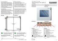
� Strip the motor cable as shown in Figure 33:<br />
1. Strip 30 mm of the insulation of the motor cable 240 mm away from the end of the cable.<br />
2. Strip 140 mm of the insulation of the motor cable at the end of the cable.<br />
3. Remove 140 mm of the outer motor cable shield of the insulated cable.<br />
4. Shorten the cables for the motor phases and the protective ground conductor of the motor to 90<br />
mm.<br />
� Connect the outer stripped motor cable shield (30 mm long) on the controller side flat to the<br />
motor shield terminal.<br />
� Connect the motor temperature sensor, the holding brake and the inner shields to connector<br />
[X6A].<br />
� Connect the motor phase and the protective ground conductor of the motor to connector [X6].<br />
� Connect the shield on the motor side flat to the connector or motor housing. Maximum length:<br />
40 mm.<br />
Insulation stripped::<br />
30 mm.<br />
Figure 33: Motor cable: Lengths of shields and cables<br />
70 mm. Motor temperature sensor and holding brake:<br />
Motor phase and motor ground conductor:<br />
90 mm.<br />
E 732 GB 111<br />
14.12.2006