Fuxx Control - ARS 2320 / ARS 2340 Instruction Manual - Kuhnke
Fuxx Control - ARS 2320 / ARS 2340 Instruction Manual - Kuhnke Fuxx Control - ARS 2320 / ARS 2340 Instruction Manual - Kuhnke
Fuxx Control ARS 2320 / ARS 2340 KUHNKE Automation 8.11.3 Pin assignment [X11] Table 40: Pin assignment [X11]: Incremental encoder output Pin no. Name Value Specification 1 A 5V / RA ≈ 66Ω *) Incremental encoder signal A 6 A# 5V / RA ≈ 66Ω *) Incremental encoder signal A# 2 B 5V / RA ≈ 66Ω *) Incremental encoder signal B 7 B# 5V / RA ≈ 66Ω *) Incremental encoder signal B# 3 N 5V / RA ≈ 66Ω *) Incremental encoder reset pulse N 8 N# 5V / RA ≈ 66Ω *) Incremental encoder reset pulse N# 4 GND - Reference GND for the encoder 9 GND - Shield for the connecting cable 5 VCC +5V ±5% 100mA Auxiliary supply, can be loaded with 100mA maximum, but short-circuit-proof ! *) The value for RA stands for the differential output resistance. 8.11.4 Cable type and configuration [X11] We recommend using encoder connection cables in which the incremental encoder signals are twisted in pairs and the individual pairs are shielded. 8.11.5 Connection notes [X11] D-SUB connector at X11 1 5 6 9 Male connector Connector housing 1 2 3 4 5 6 7 8 9 Figure 30: Pin assignment [X11]: Incremental encoder output Incremental encoder output Shield (optional) 104 E 732 GB 14.12.2006 A A# B B# N N# GND VCC Connector housing
KUHNKE Automation Fuxx Control ARS 2320 / ARS 2340 The output driver at the signal output supplies differential signals (5V) in accordance with the RS422 interface standard. Up to 32 additional controllers can be controlled by one device. 8.12 Connection: CAN bus [X4] 8.12.1 Configuration on the device [X4] � D-SUB connector, 9-pin type, male 8.12.2 Mating connector [X4] � D-SUB connector, 9-pin type, female � Housing for 9-pin D-SUB connector with bolting screws of type 4/40 UNC 8.12.3 Pin assignment [X4] Table 41: Pin assignment CAN bus [X4] Pin no. Name Value Specification 1 - - Not used 6 GND 0V CAN-GND, electrically connected to GND in the controller 2 CANL *) CAN low signal line 7 CANH *) CAN high signal line 3 GND 0V See pin no. 6 8 - - Not used 4 - - Not used 9 - - Not used 5 Schirm PE Connection for cable shield *) An external terminating resistor of 120Ω is required on both bus ends. We recommend using metal film resistors with a 5% tolerance of type 0207, e.g. made by BCC, part no.: 232215621201. E 732 GB 105 14.12.2006
- Page 53 and 54: KUHNKE Automation Fuxx Control ARS
- Page 55 and 56: KUHNKE Automation Fuxx Control ARS
- Page 57 and 58: KUHNKE Automation Fuxx Control ARS
- Page 59 and 60: KUHNKE Automation Fuxx Control ARS
- Page 61 and 62: KUHNKE Automation Fuxx Control ARS
- Page 63 and 64: KUHNKE Automation Fuxx Control ARS
- Page 65 and 66: KUHNKE Automation Fuxx Control ARS
- Page 67 and 68: KUHNKE Automation Fuxx Control ARS
- Page 69 and 70: KUHNKE Automation Fuxx Control ARS
- Page 71 and 72: KUHNKE Automation Fuxx Control ARS
- Page 73 and 74: KUHNKE Automation Fuxx Control ARS
- Page 75 and 76: KUHNKE Automation Fuxx Control ARS
- Page 77 and 78: KUHNKE Automation Fuxx Control ARS
- Page 79 and 80: KUHNKE Automation Fuxx Control ARS
- Page 81 and 82: KUHNKE Automation Fuxx Control ARS
- Page 83 and 84: KUHNKE Automation Fuxx Control ARS
- Page 85 and 86: KUHNKE Automation Fuxx Control ARS
- Page 87 and 88: KUHNKE Automation Fuxx Control ARS
- Page 89 and 90: KUHNKE Automation Fuxx Control ARS
- Page 91 and 92: KUHNKE Automation Fuxx Control ARS
- Page 93 and 94: KUHNKE Automation Fuxx Control ARS
- Page 95 and 96: KUHNKE Automation Fuxx Control ARS
- Page 97 and 98: KUHNKE Automation Fuxx Control ARS
- Page 99 and 100: KUHNKE Automation Fuxx Control ARS
- Page 101 and 102: KUHNKE Automation Fuxx Control ARS
- Page 103: KUHNKE Automation Fuxx Control ARS
- Page 107 and 108: KUHNKE Automation Fuxx Control ARS
- Page 109 and 110: KUHNKE Automation Fuxx Control ARS
- Page 111 and 112: KUHNKE Automation Fuxx Control ARS
- Page 113 and 114: KUHNKE Automation Fuxx Control ARS
- Page 115 and 116: KUHNKE Automation Fuxx Control ARS
- Page 117 and 118: KUHNKE Automation Fuxx Control ARS
- Page 119 and 120: KUHNKE Automation Fuxx Control ARS
- Page 121 and 122: KUHNKE Automation Fuxx Control ARS
- Page 123 and 124: KUHNKE Automation Fuxx Control ARS
- Page 125 and 126: KUHNKE Automation Fuxx Control ARS
- Page 127 and 128: KUHNKE Automation Fuxx Control ARS
- Page 129 and 130: KUHNKE Automation Fuxx Control ARS
- Page 131 and 132: KUHNKE Automation Fuxx Control ARS
- Page 133 and 134: KUHNKE Automation Fuxx Control ARS
- Page 135 and 136: KUHNKE Automation Fuxx Control ARS
- Page 137 and 138: KUHNKE Automation Fuxx Control ARS
- Page 139 and 140: KUHNKE Automation Fuxx Control ARS
- Page 141 and 142: KUHNKE Automation Fuxx Control ARS
- Page 143 and 144: KUHNKE Automation Fuxx Control ARS
- Page 145 and 146: KUHNKE Automation Fuxx Control ARS
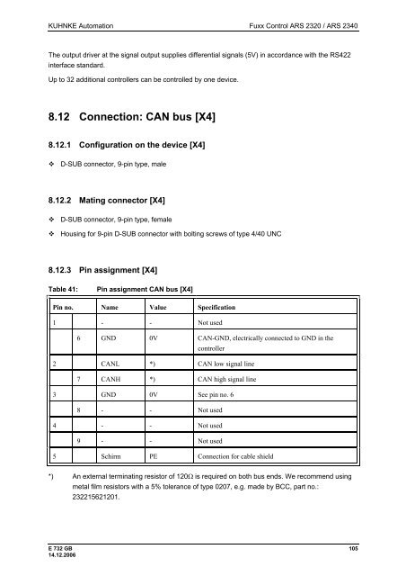
KUHNKE Automation <strong>Fuxx</strong> <strong>Control</strong> <strong>ARS</strong> <strong>2320</strong> / <strong>ARS</strong> <strong>2340</strong><br />
The output driver at the signal output supplies differential signals (5V) in accordance with the RS422<br />
interface standard.<br />
Up to 32 additional controllers can be controlled by one device.<br />
8.12 Connection: CAN bus [X4]<br />
8.12.1 Configuration on the device [X4]<br />
� D-SUB connector, 9-pin type, male<br />
8.12.2 Mating connector [X4]<br />
� D-SUB connector, 9-pin type, female<br />
� Housing for 9-pin D-SUB connector with bolting screws of type 4/40 UNC<br />
8.12.3 Pin assignment [X4]<br />
Table 41: Pin assignment CAN bus [X4]<br />
Pin no. Name Value Specification<br />
1 - - Not used<br />
6 GND 0V CAN-GND, electrically connected to GND in the<br />
controller<br />
2 CANL *) CAN low signal line<br />
7 CANH *) CAN high signal line<br />
3 GND 0V See pin no. 6<br />
8 - - Not used<br />
4 - - Not used<br />
9 - - Not used<br />
5 Schirm PE Connection for cable shield<br />
*) An external terminating resistor of 120Ω is required on both bus ends. We recommend using<br />
metal film resistors with a 5% tolerance of type 0207, e.g. made by BCC, part no.:<br />
232215621201.<br />
E 732 GB 105<br />
14.12.2006


