Fuxx Control - ARS 2320 / ARS 2340 Instruction Manual - Kuhnke
Fuxx Control - ARS 2320 / ARS 2340 Instruction Manual - Kuhnke Fuxx Control - ARS 2320 / ARS 2340 Instruction Manual - Kuhnke
Fuxx Control ARS 2320 / ARS 2340 KUHNKE Automation 8.9.5 Connection notes [X2B] D-SUB connector at X2B 1 8 9 15 Male connector Connector housing 1 2 3 4 5 6 7 8 9 10 11 12 13 14 15 Output of the analog incremental encoder at the motor Figure 26: Pin assignment: Analog incremental encoder - option [X2B] D-SUB-connector at X2B 1 9 8 15 Male connector Connector housing 1 2 3 4 9 10 11 12 5 13 6 14 7 15 8 TEMP- TEMP+ U_SENS+ U_SENS- COS_Z1 #COS_Z1 SIN_Z1 #SIN_Z1 COS_Z0 #COS_Z0 #SIN_Z0 Shield (optional) Connector housing 100 E 732 GB 14.12.2006 US GND R #R SIN_Z0 Output of the analog incremental encoder with serial Interface at the motor TEMP- TEMP+ U_SENS+ U_SENS- US GND DATA #DATA SCLK #SCLK COS_Z0 #COS_Z0 SIN_Z0 #SIN_Z0 Shield (optional) Connector housing Figure 27: Pin assignment: Incremental encoder with serial interface (e.g. EnDat, HIPERFACE) - option [X2B]
KUHNKE Automation Fuxx Control ARS 2320 / ARS 2340 D-SUB connector at X2B 1 8 9 15 Male connector Connector housing 1 2 3 4 5 6 7 8 9 10 11 12 13 14 15 Output of the incremental encoder with serial interface at the motor Figure 28: Pin assignment: Digital incremental encoder - option [X2B] TEMP- TEMP+ SENSE+ SENSE- Shield (optional) Connector housing E 732 GB 101 14.12.2006 VCC GND N N# HALL_U HALL_V HALL_W 8.10 Connection: Incremental encoder input [X10] 8.10.1 Configuration on the device [X10] � D-SUB connector, 9-pin type, female 8.10.2 Mating connector [X10] � D-SUB connector, 9-pin type, male � Housing for 9-pin D-SUB connector with bolting screws of type 4/40 UNC A A# B B#
- Page 49 and 50: KUHNKE Automation Fuxx Control ARS
- Page 51 and 52: KUHNKE Automation Fuxx Control ARS
- Page 53 and 54: KUHNKE Automation Fuxx Control ARS
- Page 55 and 56: KUHNKE Automation Fuxx Control ARS
- Page 57 and 58: KUHNKE Automation Fuxx Control ARS
- Page 59 and 60: KUHNKE Automation Fuxx Control ARS
- Page 61 and 62: KUHNKE Automation Fuxx Control ARS
- Page 63 and 64: KUHNKE Automation Fuxx Control ARS
- Page 65 and 66: KUHNKE Automation Fuxx Control ARS
- Page 67 and 68: KUHNKE Automation Fuxx Control ARS
- Page 69 and 70: KUHNKE Automation Fuxx Control ARS
- Page 71 and 72: KUHNKE Automation Fuxx Control ARS
- Page 73 and 74: KUHNKE Automation Fuxx Control ARS
- Page 75 and 76: KUHNKE Automation Fuxx Control ARS
- Page 77 and 78: KUHNKE Automation Fuxx Control ARS
- Page 79 and 80: KUHNKE Automation Fuxx Control ARS
- Page 81 and 82: KUHNKE Automation Fuxx Control ARS
- Page 83 and 84: KUHNKE Automation Fuxx Control ARS
- Page 85 and 86: KUHNKE Automation Fuxx Control ARS
- Page 87 and 88: KUHNKE Automation Fuxx Control ARS
- Page 89 and 90: KUHNKE Automation Fuxx Control ARS
- Page 91 and 92: KUHNKE Automation Fuxx Control ARS
- Page 93 and 94: KUHNKE Automation Fuxx Control ARS
- Page 95 and 96: KUHNKE Automation Fuxx Control ARS
- Page 97 and 98: KUHNKE Automation Fuxx Control ARS
- Page 99: KUHNKE Automation Fuxx Control ARS
- Page 103 and 104: KUHNKE Automation Fuxx Control ARS
- Page 105 and 106: KUHNKE Automation Fuxx Control ARS
- Page 107 and 108: KUHNKE Automation Fuxx Control ARS
- Page 109 and 110: KUHNKE Automation Fuxx Control ARS
- Page 111 and 112: KUHNKE Automation Fuxx Control ARS
- Page 113 and 114: KUHNKE Automation Fuxx Control ARS
- Page 115 and 116: KUHNKE Automation Fuxx Control ARS
- Page 117 and 118: KUHNKE Automation Fuxx Control ARS
- Page 119 and 120: KUHNKE Automation Fuxx Control ARS
- Page 121 and 122: KUHNKE Automation Fuxx Control ARS
- Page 123 and 124: KUHNKE Automation Fuxx Control ARS
- Page 125 and 126: KUHNKE Automation Fuxx Control ARS
- Page 127 and 128: KUHNKE Automation Fuxx Control ARS
- Page 129 and 130: KUHNKE Automation Fuxx Control ARS
- Page 131 and 132: KUHNKE Automation Fuxx Control ARS
- Page 133 and 134: KUHNKE Automation Fuxx Control ARS
- Page 135 and 136: KUHNKE Automation Fuxx Control ARS
- Page 137 and 138: KUHNKE Automation Fuxx Control ARS
- Page 139 and 140: KUHNKE Automation Fuxx Control ARS
- Page 141 and 142: KUHNKE Automation Fuxx Control ARS
- Page 143 and 144: KUHNKE Automation Fuxx Control ARS
- Page 145 and 146: KUHNKE Automation Fuxx Control ARS
<strong>Fuxx</strong> <strong>Control</strong> <strong>ARS</strong> <strong>2320</strong> / <strong>ARS</strong> <strong>2340</strong> KUHNKE Automation<br />
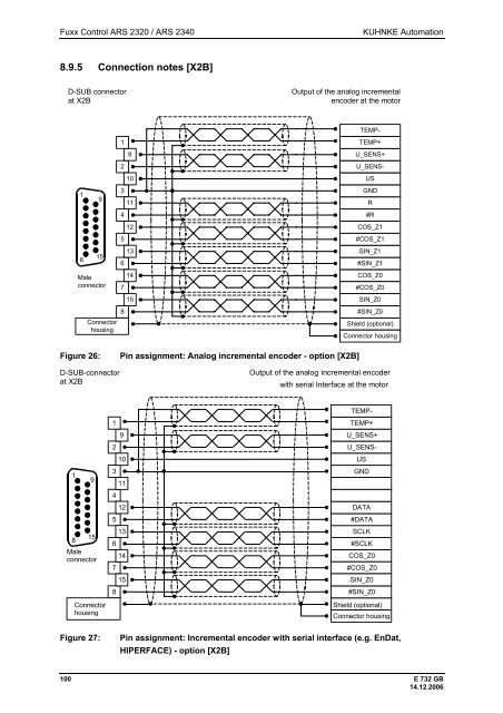
8.9.5 Connection notes [X2B]<br />
D-SUB connector<br />
at X2B<br />
1<br />
8<br />
9<br />
15<br />
Male<br />
connector<br />
Connector<br />
housing<br />
1<br />
2<br />
3<br />
4<br />
5<br />
6<br />
7<br />
8<br />
9<br />
10<br />
11<br />
12<br />
13<br />
14<br />
15<br />
Output of the analog incremental<br />
encoder at the motor<br />
Figure 26: Pin assignment: Analog incremental encoder - option [X2B]<br />
D-SUB-connector<br />
at X2B<br />
1<br />
9<br />
8<br />
15<br />
Male<br />
connector<br />
Connector<br />
housing<br />
1<br />
2<br />
3<br />
4<br />
9<br />
10<br />
11<br />
12<br />
5<br />
13<br />
6<br />
14<br />
7<br />
15<br />
8<br />
TEMP-<br />
TEMP+<br />
U_SENS+<br />
U_SENS-<br />
COS_Z1<br />
#COS_Z1<br />
SIN_Z1<br />
#SIN_Z1<br />
COS_Z0<br />
#COS_Z0<br />
#SIN_Z0<br />
Shield (optional)<br />
Connector housing<br />
100 E 732 GB<br />
14.12.2006<br />
US<br />
GND<br />
R<br />
#R<br />
SIN_Z0<br />
Output of the analog incremental encoder<br />
with serial Interface at the motor<br />
TEMP-<br />
TEMP+<br />
U_SENS+<br />
U_SENS-<br />
US<br />
GND<br />
DATA<br />
#DATA<br />
SCLK<br />
#SCLK<br />
COS_Z0<br />
#COS_Z0<br />
SIN_Z0<br />
#SIN_Z0<br />
Shield (optional)<br />
Connector housing<br />
Figure 27: Pin assignment: Incremental encoder with serial interface (e.g. EnDat,<br />
HIPERFACE) - option [X2B]


