Ventura IPC Instruction Manual pdf - Kuhnke
Ventura IPC Instruction Manual pdf - Kuhnke Ventura IPC Instruction Manual pdf - Kuhnke
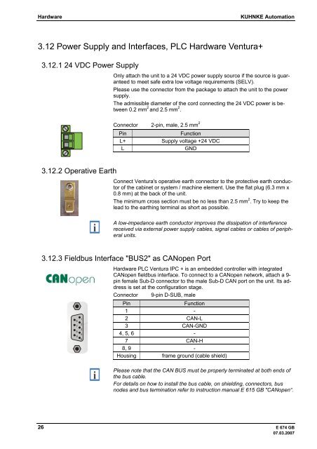
Hardware KUHNKE Automation 3.12 Power Supply and Interfaces, PLC Hardware Ventura+ 3.12.1 24 VDC Power Supply 3.12.2 Operative Earth Only attach the unit to a 24 VDC power supply source if the source is guaranteed to meet safe extra low voltage requirements (SELV). Please use the connector from the package to attach the unit to the power supply. The admissible diameter of the cord connecting the 24 VDC power is between 0.2 mm 2 and 2.5 mm 2 . Connector 2-pin, male, 2.5 mm 2 Pin Function L+ Supply voltage +24 VDC L GND Connect Ventura's operative earth connector to the protective earth conductor of the cabinet or system / machine element. Use the flat plug (6.3 mm x 0.8 mm) at the back of the unit. The minimum cross section must be no less than 2.5 mm 2 . Try to keep the lead to the earthing terminal as short as possible. A low-impedance earth conductor improves the dissipation of interference received via external power supply cables, signal cables or cables of peripheral units. 3.12.3 Fieldbus Interface "BUS2" as CANopen Port 1 6 2 7 3 8 4 9 5 Hardware PLC Ventura IPC + is an embedded controller with integrated CANopen fieldbus interface. To connect to a CANopen network, attach a 9pin female Sub-D connector to the male Sub-D CAN port on the unit. Its address is set at the configuration stage. Connector 9-pin D-SUB, male Pin Function 1 - 2 CAN-L 3 CAN-GND 4, 5, 6 - 7 CAN-H 8, 9 - Housing frame ground (cable shield) Please note that the CAN BUS must be properly terminated at both ends of the bus cable. For details on how to install the bus cable, on shielding, connectors, bus nodes and bus termination refer to instruction manual E 615 GB "CANopen“. 26 E 674 GB 07.03.2007
KUHNKE Automation Hardware 3.12.4 Fieldbus Interface "BUS3" as PROFIBUS Port 5 9 4 8 3 7 2 6 1 3.12.5 Digital Combi I/O "DI/DO" 1 2 4 Hardware PLC Ventura IPC + can be optionally equipped with a PROFIBUS DP master port. To connect to a bus, attach a 9-pin male Sub-D PROFIBUS connector to the female PROFIBUS port on the unit. Run the bus configuration utility to set the network's baud rate and address, then transfer the hardware parameters to the hardware PLC. It is not necessary to change any bus parameter settings at the device hardware. Connector 9-pin D-SUB, male Pin Function 1 (attached to housing frame) 2 - 3 RxD/TxD-P (Data +) 4 - 5 DGnd 6 VP (+5 V power, max. 100 mA) 7 - 8 RxD/TxD-N (Data -) 9 - Housing frame ground (connected with pin 1) Attach the cable shield to the connector housing. Please note that the PROFIBUS must be properly terminated at both ends of the bus cable. The PROFIBUS jack of hardware PLC Ventura IPC + supplies the required voltage. For details on how to install the bus cable, on shielding, connectors, bus nodes and bus termination refer to instruction manual E 611 GB "PROFI- BUS-DP“. Hardware PLC Ventura+ features 5 digital combi I/Os "DI/DO 0 ... 4" which can be set to act as inputs, special-function inputs or as outputs. Connector 5-pin, male, 2.5 mm 2 Pin Function Input Output (short-circuit-proof) 0 Interrupt A1 track counter, 24 VDC/0.5 A 1 Interrupt B1 track - 24 VDC/0.5 A 2 Interrupt A2 track counter, 24 VDC/0.5 A 3 Interrupt A3 track - 24 VDC/0.5 A 4 Interrupt Ref track - - If used as inputs, DI/DO 0 to DI/DO 4 are marked by their very short rising delay. User programs can read them just like normal inputs. To be able to immediately react to events, they are capable of requested processor interrupts. LEDs lighting up green show that there is either an input signal or that the output is active. Active outputs can be checked via the input address. Optional E 674 GB 27 07.03.2007
- Page 1 and 2: Kuhnke Electronics Instruction Manu
- Page 3 and 4: KUHNKE Automation Table of Contents
- Page 5 and 6: KUHNKE Automation Table of Contents
- Page 7 and 8: 1 Introduction Performance in a nut
- Page 9 and 10: KUHNKE Automation Reliability, Safe
- Page 11 and 12: KUHNKE Automation Reliability, Safe
- Page 13 and 14: KUHNKE Automation Hardware 3 Ventur
- Page 15 and 16: KUHNKE Automation Hardware 3.4 Tech
- Page 17 and 18: KUHNKE Automation Hardware 3.6 Phys
- Page 19 and 20: KUHNKE Automation Hardware 3.7.4 Gr
- Page 21 and 22: KUHNKE Automation Hardware 3.7.7 Et
- Page 23 and 24: KUHNKE Automation Hardware 3.9 Stor
- Page 25: KUHNKE Automation Hardware 3.11 Ext
- Page 29 and 30: KUHNKE Automation Hardware 3.13 Ven
- Page 31 and 32: KUHNKE Automation Hardware 4 Instal
- Page 33 and 34: KUHNKE Automation Software 5 Start-
- Page 35 and 36: KUHNKE Automation Software Windows
- Page 37 and 38: KUHNKE Automation Software 6.1 Comp
- Page 39 and 40: KUHNKE Automation Software 6.2.3 OP
- Page 41 and 42: KUHNKE Automation Software 6.3.3 Ul
- Page 43 and 44: KUHNKE Automation Software 6.5 Vent
- Page 45 and 46: KUHNKE Automation Software 7.1.2 Co
- Page 47 and 48: KUHNKE Automation Software 7.1.5 OP
- Page 49 and 50: KUHNKE Automation Software • Deve
- Page 51 and 52: KUHNKE Automation Software This com
- Page 53 and 54: KUHNKE Automation Software Sometime
- Page 55 and 56: KUHNKE Automation Software 7.5 Conn
- Page 57 and 58: KUHNKE Automation Software 7.5.2 Et
- Page 59 and 60: KUHNKE Automation Software • Star
- Page 61 and 62: KUHNKE Automation Software 9 Mainte
- Page 63 and 64: KUHNKE Automation Appendix 10 Appen
- Page 65 and 66: KUHNKE Automation Appendix E 674 GB
- Page 67 and 68: KUHNKE Automation Appendix Max. pow
- Page 69 and 70: KUHNKE Automation Appendix 10.3 Dim
- Page 71 and 72: KUHNKE Automation Appendix 10.3.3 V
- Page 73 and 74: KUHNKE Automation Appendix 10.4 Ven
- Page 75 and 76: KUHNKE Automation Appendix 10.4.2 V
Hardware KUHNKE Automation<br />
3.12 Power Supply and Interfaces, PLC Hardware <strong>Ventura</strong>+<br />
3.12.1 24 VDC Power Supply<br />
3.12.2 Operative Earth<br />
Only attach the unit to a 24 VDC power supply source if the source is guaranteed<br />
to meet safe extra low voltage requirements (SELV).<br />
Please use the connector from the package to attach the unit to the power<br />
supply.<br />
The admissible diameter of the cord connecting the 24 VDC power is between<br />
0.2 mm 2 and 2.5 mm 2 .<br />
Connector 2-pin, male, 2.5 mm 2<br />
Pin Function<br />
L+ Supply voltage +24 VDC<br />
L GND<br />
Connect <strong>Ventura</strong>'s operative earth connector to the protective earth conductor<br />
of the cabinet or system / machine element. Use the flat plug (6.3 mm x<br />
0.8 mm) at the back of the unit.<br />
The minimum cross section must be no less than 2.5 mm 2 . Try to keep the<br />
lead to the earthing terminal as short as possible.<br />
A low-impedance earth conductor improves the dissipation of interference<br />
received via external power supply cables, signal cables or cables of peripheral<br />
units.<br />
3.12.3 Fieldbus Interface "BUS2" as CANopen Port<br />
1<br />
6<br />
2<br />
7<br />
3<br />
8<br />
4<br />
9<br />
5<br />
Hardware PLC <strong>Ventura</strong> <strong>IPC</strong> + is an embedded controller with integrated<br />
CANopen fieldbus interface. To connect to a CANopen network, attach a 9pin<br />
female Sub-D connector to the male Sub-D CAN port on the unit. Its address<br />
is set at the configuration stage.<br />
Connector 9-pin D-SUB, male<br />
Pin Function<br />
1 -<br />
2 CAN-L<br />
3 CAN-GND<br />
4, 5, 6 -<br />
7 CAN-H<br />
8, 9 -<br />
Housing frame ground (cable shield)<br />
Please note that the CAN BUS must be properly terminated at both ends of<br />
the bus cable.<br />
For details on how to install the bus cable, on shielding, connectors, bus<br />
nodes and bus termination refer to instruction manual E 615 GB "CANopen“.<br />
26 E 674 GB<br />
07.03.2007


