Ventura IPC Instruction Manual pdf - Kuhnke
Ventura IPC Instruction Manual pdf - Kuhnke
Ventura IPC Instruction Manual pdf - Kuhnke

Create successful ePaper yourself
Turn your PDF publications into a flip-book with our unique Google optimized e-Paper software.
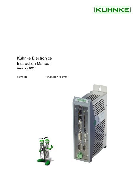
<strong>Kuhnke</strong> Electronics<br />
<strong>Instruction</strong> <strong>Manual</strong><br />
<strong>Ventura</strong> <strong>IPC</strong><br />
E 674 GB 07.03.2007/ 105.745
This instruction manual is primarily intended for use by design, project and development engineers. It does not contain any availability<br />
information. Data is only given to describe the product and must not be regarded as guaranteed properties in the legal sense. Any<br />
claims for damages - on whatever legal grounds - are excluded except for instances of deliberate intent or gross negligence on our<br />
part.<br />
We reserve the rights for errors, omissions and modifications.<br />
Reproduction even of extracts only with the editor's express and written prior consent.
KUHNKE Automation Table of Contents<br />
Table of Contents<br />
1 Introduction......................................................................................................................................................7<br />
2 Reliability, Safety .............................................................................................................................................8<br />
2.1 Application............................................................................................................................................8<br />
2.2 Target Group........................................................................................................................................8<br />
2.3 Reliability..............................................................................................................................................8<br />
2.4 Symbols ...............................................................................................................................................8<br />
2.4.1 Danger................................................................................................................................................9<br />
2.4.2 Attention .............................................................................................................................................9<br />
2.4.3 Note....................................................................................................................................................9<br />
2.4.4 Under Construction ............................................................................................................................9<br />
2.4.5 <strong>Instruction</strong>...........................................................................................................................................9<br />
2.5 Safety ...................................................................................................................................................9<br />
2.5.1 Project Planning and Installation......................................................................................................10<br />
2.5.2 Maintenance and Servicing..............................................................................................................10<br />
2.6 Electromagnetic Compatibility............................................................................................................11<br />
2.6.1 Definition ..........................................................................................................................................11<br />
2.6.2 Interference Emission ......................................................................................................................11<br />
2.6.3 General Notes on Installation...........................................................................................................11<br />
2.6.4 Electrical Immission Safeguard........................................................................................................12<br />
2.6.5 Cable Routing and Wiring ................................................................................................................12<br />
2.6.6 Location of Installation .....................................................................................................................12<br />
2.6.7 Particular Sources of Interference....................................................................................................12<br />
3 <strong>Ventura</strong> <strong>IPC</strong> System Description...................................................................................................................13<br />
3.1 Overview ............................................................................................................................................13<br />
3.2 <strong>Ventura</strong> <strong>IPC</strong> + System Description ....................................................................................................14<br />
3.3 Application..........................................................................................................................................14<br />
3.4 Technical Properties ..........................................................................................................................15<br />
3.5 Model Variant.....................................................................................................................................16<br />
3.6 Physical Design..................................................................................................................................17<br />
3.7 <strong>Ventura</strong> <strong>IPC</strong> Power Supply and Ports................................................................................................18<br />
3.7.1 24 VDC Power Supply .....................................................................................................................18<br />
3.7.2 Operative Earth ................................................................................................................................18<br />
3.7.3 Serial Ports "COM1 and COM2" ......................................................................................................18<br />
3.7.4 Graphics Adapter "DVI / VGA" .........................................................................................................19<br />
3.7.5 Interface "PS / 2" ..............................................................................................................................20<br />
3.7.6 Interface "USB1","USB2" .................................................................................................................20<br />
3.7.7 Ethernet "LAN1", "LAN2"..................................................................................................................21<br />
3.7.8 Fieldbus Interface "BUS1" as CANopen Port ..................................................................................22<br />
3.8 <strong>Ventura</strong> <strong>IPC</strong> Controls .........................................................................................................................22<br />
3.8.1 "RESET" Button ...............................................................................................................................22<br />
3.9 Storage Media (Removable Disk)......................................................................................................23<br />
3.9.1 Compact Flash Card Slot "CF-CARD" .............................................................................................23<br />
3.9.2 Compact Flash Card Slot "CF-CARD" .............................................................................................23<br />
3.10 LED Indicators, <strong>Ventura</strong> <strong>IPC</strong> ..........................................................................................................23<br />
3.10.1 Status LEDs ...................................................................................................................................23<br />
3.11 External Elements, <strong>Ventura</strong> <strong>IPC</strong> + Hardware PLC.........................................................................25<br />
3.12 Power Supply and Interfaces, PLC Hardware <strong>Ventura</strong>+................................................................26<br />
3.12.1 24 VDC Power Supply ...................................................................................................................26<br />
3.12.2 Operative Earth ..............................................................................................................................26<br />
E 674 GB 3<br />
07.03.2007
Table of Contents KUHNKE Automation<br />
3.12.3 Fieldbus Interface "BUS2" as CANopen Port ................................................................................26<br />
3.12.4 Fieldbus Interface "BUS3" as PROFIBUS Port..............................................................................27<br />
3.12.5 Digital Combi I/O "DI/DO" ..............................................................................................................27<br />
3.12.6 Serial RS 232 Interface ..................................................................................................................28<br />
3.13 <strong>Ventura</strong>+ Hardware PLC Controls..................................................................................................29<br />
3.13.1 "RESET" Button .............................................................................................................................29<br />
3.14 <strong>Ventura</strong> Indicators ..........................................................................................................................29<br />
3.14.1 Status LEDs ...................................................................................................................................29<br />
3.15 Error Codes ....................................................................................................................................30<br />
4 Installation .....................................................................................................................................................31<br />
4.1 Flange Plate Installation.....................................................................................................................31<br />
4.1.1 To Install the Screw Plate Adapter (<strong>Ventura</strong> <strong>IPC</strong> 300 / 700) ...........................................................31<br />
4.1.2 To Install the Device.........................................................................................................................31<br />
4.2 Mounting on Top-hat Rail (<strong>Ventura</strong> <strong>IPC</strong> 300 / 700) ...........................................................................32<br />
4.2.1 To Attach the Rail Adapter to the Device.........................................................................................32<br />
4.2.2 To Attach the Device to the Top-hat Rail .........................................................................................32<br />
4.2.3 To Remove the Device from the Top-hat Rail..................................................................................32<br />
5 Start-up..........................................................................................................................................................33<br />
5.1 Installing CoDeSys on the Programming PC.....................................................................................33<br />
5.1.1 CoDeSys Target Installation ............................................................................................................33<br />
5.2 CoDeSys Programming PC Setup.....................................................................................................34<br />
5.2.1 Ethernet Connections of <strong>Ventura</strong> <strong>IPC</strong>..............................................................................................34<br />
5.2.2 Programming PC Interface Setup ....................................................................................................34<br />
5.2.3 CoDeSys Target System Setting on the Programming PC .............................................................35<br />
6 Windows ® XP Embedded ..............................................................................................................................36<br />
6.1 Components.......................................................................................................................................37<br />
6.1.1 General Data....................................................................................................................................37<br />
6.1.2 Breakdown of Key Components of the Windows ® XP embedded Image .......................................37<br />
6.1.3 XP embedded File System...............................................................................................................37<br />
6.2 Tools ..................................................................................................................................................38<br />
6.2.1 <strong>Ventura</strong> touch Calibration.................................................................................................................38<br />
6.2.2 Temperature Monitor........................................................................................................................38<br />
6.2.3 OPC Server......................................................................................................................................39<br />
6.3 IPHelper .............................................................................................................................................39<br />
6.3.1 USB Memory Stick ...........................................................................................................................39<br />
6.3.2 Create New SID ...............................................................................................................................40<br />
6.3.3 UltraVNC Remote Control Option ....................................................................................................41<br />
6.4 File Transfer .......................................................................................................................................42<br />
6.5 <strong>Ventura</strong> SlotPLC Gateway Driver ......................................................................................................43<br />
6.5.1 Installation ........................................................................................................................................43<br />
6.5.2 To verify correct installation of the <strong>Ventura</strong> SlotPLC gateway drivers.............................................43<br />
7 Windows ® CE.NET ........................................................................................................................................44<br />
7.1.1 Windows CE.NET File System.........................................................................................................44<br />
7.1.2 Components.....................................................................................................................................45<br />
7.1.3 <strong>Ventura</strong> touch Calibration.................................................................................................................46<br />
7.1.4 Running Applications .......................................................................................................................46<br />
7.1.5 OPC Server......................................................................................................................................47<br />
7.1.6 Printers .............................................................................................................................................47<br />
7.1.7 USB Memory Stick ...........................................................................................................................47<br />
7.1.8 Remote Control Option ....................................................................................................................47<br />
4 E 674 GB<br />
07.03.2007
KUHNKE Automation Table of Contents<br />
7.2 Connecting Using "ActiveSync" .........................................................................................................48<br />
7.3 Connecting via the Network ...............................................................................................................50<br />
7.4 Tools ..................................................................................................................................................52<br />
7.4.1 Check System Status Using "systemhealth"....................................................................................52<br />
7.4.2 ScreenRes........................................................................................................................................52<br />
7.4.3 Remote Debugging in Microsoft Visual Studio .NET 2003 ..............................................................54<br />
7.5 Connecting with <strong>Ventura</strong> <strong>IPC</strong>'s Software PLC (Windows CE)...........................................................55<br />
7.5.1 Serial Interface .................................................................................................................................55<br />
7.5.2 Ethernet Interface.............................................................................................................................57<br />
8 Troubleshooting.............................................................................................................................................60<br />
8.1 General Problems ..............................................................................................................................60<br />
9 Maintenance ..................................................................................................................................................61<br />
9.1 Replacing the Battery.........................................................................................................................61<br />
9.2 Handling of Memory Cards ................................................................................................................62<br />
10 Appendix......................................................................................................................................................63<br />
10.1 Licencing ........................................................................................................................................63<br />
10.2 Technical Data................................................................................................................................64<br />
10.2.1 Basic Data......................................................................................................................................64<br />
10.2.2 Indicators........................................................................................................................................66<br />
10.2.3 Communication ports .....................................................................................................................66<br />
10.2.4 Hardware PLC (<strong>Ventura</strong>+)..............................................................................................................66<br />
10.2.5 Integrated Inputs and Outputs (<strong>Ventura</strong> +) ....................................................................................67<br />
10.2.6 Communication Ports (<strong>Ventura</strong> +)..................................................................................................68<br />
10.2.7 Permits ...........................................................................................................................................68<br />
10.3 Dimensions, <strong>Ventura</strong> <strong>IPC</strong> ...............................................................................................................69<br />
10.3.1 Outer Dimensions, <strong>Ventura</strong> <strong>IPC</strong> 300..............................................................................................69<br />
10.3.2 <strong>Ventura</strong> <strong>IPC</strong> 300 / 700, Drilling Jig for Screw Plate Adapter..........................................................70<br />
10.3.3 <strong>Ventura</strong> <strong>IPC</strong> 300 / 700, Rail Adapter..............................................................................................71<br />
10.3.4 Outer Dimensions, <strong>Ventura</strong> <strong>IPC</strong> 800 / 1000...................................................................................72<br />
10.4 <strong>Ventura</strong> <strong>IPC</strong> 800 / 1000, Drilling Jig ...............................................................................................73<br />
10.4.1 Outer Dimensions <strong>Ventura</strong> 300+ / <strong>Ventura</strong> 300FB ........................................................................74<br />
10.4.2 <strong>Ventura</strong> <strong>IPC</strong> 300+ / 300FB / 700+ / 700FB, Drilling Jig for Screw Plate Adapter .........................75<br />
10.4.3 <strong>Ventura</strong> <strong>IPC</strong> 300+ / 300FB / 700+ / 700FB, Rail Adapter ..............................................................76<br />
10.4.4 Outer Dimensions, <strong>Ventura</strong> 800+ / 800 FB / 1000+ / 1000FB .......................................................77<br />
10.4.5 <strong>Ventura</strong> <strong>IPC</strong> 800+ / 800FB / 1000+ / 1000FB, Drilling Jig for Screw Plate Adapter .....................78<br />
10.4.6 Emergency Action ..........................................................................................................................79<br />
10.5 Taking out of Service......................................................................................................................79<br />
10.6 Disposal..........................................................................................................................................79<br />
10.7 Order Specifications .......................................................................................................................80<br />
10.7.1 Basic Units .....................................................................................................................................80<br />
10.7.2 Accessories....................................................................................................................................81<br />
10.8 References .....................................................................................................................................83<br />
10.9 Sales & Service ..............................................................................................................................84<br />
10.9.1 Main Factory in Malente.................................................................................................................84<br />
10.9.2 Sales Germany...............................................................................................................................84<br />
10.10 Index...............................................................................................................................................85<br />
E 674 GB 5<br />
07.03.2007
Table of Contents KUHNKE Automation<br />
6 E 674 GB<br />
07.03.2007
1 Introduction<br />
Performance in a nutshell<br />
Introduction<br />
The modular design and standard on-board interfaces of PC-based controller<br />
<strong>Ventura</strong> support flexible control solutions providing for future developments<br />
in automation. Its passive chiller, fanless operation and the CF cards<br />
used as mass storage media ensure advanced flexibility and speed and safety.<br />
The mechanical and electrical design of the basic <strong>Ventura</strong> <strong>IPC</strong> model provides<br />
reliable control and actuation of machines under tough everyday conditions<br />
of the industry and warrants that all data is safe even in the event of<br />
power failures. It is shock-proof and vibration-proof, features low-voltage<br />
protection and EMC compliance plus compatibility with temperatures up to<br />
50 °Celsius. Standard ports to CANopen, DVI, Ethernet, COM and USB let<br />
<strong>Ventura</strong> <strong>IPC</strong> satisfy all communication needs. Users are supported by<br />
CoDeSys, the stable and real-time control and programming system, in conjunction<br />
with the real-time operating system, Microsoft® Windows® CE and<br />
XP embedded. Two compact flash drives allow application and machine<br />
data to be separated from the operating system. The <strong>Ventura</strong> <strong>IPC</strong> platform<br />
installs or mounts either in a switching cabinet or immediately behind the<br />
new <strong>Ventura</strong> <strong>IPC</strong> Touch.<br />
E 674 GB 7<br />
07.03.2007
Reliability, Safety KUHNKE Automation<br />
2 Reliability, Safety<br />
2.1 Application<br />
2.2 Target Group<br />
2.3 Reliability<br />
2.4 Symbols<br />
<strong>Kuhnke</strong> products are designed as resources for use in industrial environments.<br />
All other applications need to be discussed with the factory first. The manufacturer<br />
shall neither be liable for any other than the intended use of our<br />
products nor for any ensuing damages. The risk shall be borne by the operator<br />
alone. The use as intended includes that you read and apply all information<br />
and instructions contained in this manual.<br />
This instruction manual contains all information necessary for the use of the<br />
described product (control device, control terminal, software, etc.) according<br />
to instructions. It is written for design, project planning, servicing and commissioning<br />
experts. For proper understanding and error-free application of<br />
technical descriptions, instructions for use and particularly of notes of danger<br />
and warning, extensive knowledge of automation technology is compulsory.<br />
Reliability of <strong>Kuhnke</strong> products is brought to the highest possible standards<br />
by extensive and cost-effective means in their design and manufacture.<br />
These include:<br />
• selecting high-quality components,<br />
• quality agreements with our suppliers,<br />
• actions to avoid static charges when handling MOS circuits,<br />
• worst case planning and design of all circuits,<br />
• visual inspections at various stages of fabrication,<br />
• computer-aided tests of all assemblies and their interaction in the circuit,<br />
• statistical assessment of the quality of fabrication and of all returned<br />
goods for the immediate taking of appropriate corrective actions.<br />
Despite the measures described in chapter 2.3 the occurrence of faults or<br />
errors in electronic control units - even if most highly improbable - must be<br />
taken into consideration.<br />
Please pay particular attention to the additional notices which we have<br />
marked by symbols throughout this instruction manual. While some of these<br />
notices make you aware of possible dangers, others are intended as a<br />
means of orientation. They are described further down below in descending<br />
order of importance.<br />
8 E 674 GB<br />
07.03.2007
KUHNKE Automation Reliability, Safety<br />
2.4.1 Danger<br />
2.4.2 Attention<br />
2.4.3 Note<br />
2.4.4 Under Construction<br />
2.4.5 <strong>Instruction</strong><br />
2.5 Safety<br />
This symbol warns you of dangers which may cause death or grievous bodily<br />
harm if operators fail to implement the precautions described.<br />
This symbol draws your attention to information you must take a look at to<br />
avoid malfunctions, possible material damage or dangerous states.<br />
This symbol draws your attention to additional information concerning the<br />
use of the described product. This may include cross references to information<br />
found elsewhere (e.g. in other manuals).<br />
This symbol tells you that the function described was not or not fully available<br />
at the time this document went to press.<br />
Wherever you see these symbols in the left margin, you will find a list of<br />
steps instructing you to take the appropriate computer or hardware actions.<br />
They are intended as a means of orientation wherever working steps and<br />
background information alternate (e.g. in tutorials).<br />
Our products normally become part of larger systems or installations. The information<br />
below is intended to help you integrate the product into its environment<br />
without dangers to humans or material/equipment.<br />
To achieve a high degree of conceptual safety in planning and installing an<br />
electronic controller, it is essential to exactly follow the instructions given in<br />
the manual because wrong handling could lead to rendering measures against<br />
dangers ineffective or to creating additional dangers.<br />
E 674 GB 9<br />
07.03.2007
Reliability, Safety KUHNKE Automation<br />
2.5.1 Project Planning and Installation<br />
2.5.2 Maintenance and Servicing<br />
• 24 VDC power supply: generate as electrically safely separated low<br />
voltage. Suitable devices are, for example, split transformers constructed<br />
in compliance with European Standard EN 60742 (corresponds<br />
to VDE 0551).<br />
• Power breakdowns or power fades: the program structure is to ensure<br />
that a defined state at restart excludes all dangerous states.<br />
• Emergency switch-off installations must comply with EN 60204/IEC 204<br />
(VDE 0113). They must be effective at any time.<br />
• Safety and precautions regulations for qualified applications have to be<br />
complied with.<br />
• Please pay particular attention to the notices of warning which, at relevant<br />
places, will make you aware of possible sources of dangerous mistakes<br />
or faults.<br />
• Relevant standards and VDE regulations are to be complied with in<br />
every case.<br />
• Control elements are to be installed in such a way as to exclude unintended<br />
operation.<br />
• Control cables are to be laid in such a way as to exclude interference<br />
(inductive or capacitive) which could influence controller operation or its<br />
functionality.<br />
• Precautions regulation VBG 4.0 must be observed when measuring or<br />
checking a controller in a power-up condition. This applies to section 8<br />
(Admissible deviations when working on parts) in particular.<br />
• Repairs must be carried out by specially trained <strong>Kuhnke</strong> staff only (usually<br />
in the main factory in Malente). Warranty expires in every other<br />
case.<br />
• Spare parts:<br />
• Only use parts approved of by <strong>Kuhnke</strong>. Only genuine <strong>Kuhnke</strong> modules<br />
must be used in modular controllers.<br />
• Modular systems: always plug or unplug modules in a power-down state.<br />
You might otherwise damage the modules or (possibly not immediately<br />
recognisably!) inhibit their functionality.<br />
• Always dispose of any batteries and accumulators as hazardous waste.<br />
10 E 674 GB<br />
07.03.2007
KUHNKE Automation Reliability, Safety<br />
2.6 Electromagnetic Compatibility<br />
2.6.1 Definition<br />
2.6.2 Interference Emission<br />
2.6.3 General Notes on Installation<br />
Electromagnetic compatibility is the ability of a device to function satisfactorily<br />
in its electromagnetic environment without itself causing any electromagnetic<br />
interference that would be intolerable to other devices in this environment.<br />
Of all known phenomena of electromagnetic noise, only a certain range occurs<br />
at the location of a given device. These kinds of noise are specified in<br />
the applicable product standards.<br />
The design and immunity to interference of programmable logic controllers<br />
are internationally governed by standard<br />
IEC 61131-2 which, in Europe, has been the basis for European Standard<br />
EN 61131-2.<br />
Refer to IEC 61131-4, User's Guideline, for general installation instructions<br />
to be complied with to ensure that hardware interface factors and the ensuing<br />
noise voltages are limited to tolerable levels.<br />
Interfering emission of electromagnetic fields, HF<br />
compliant to EN 55011, limiting value class A, Group 1<br />
If the controller is designed for use in residential areas, high-frequency emissions<br />
must comply with limiting value class B as described in EN 55011.<br />
Fitting the controller into earthed metal cabinets and in-stalling filters in the<br />
supply lines may produce a shielding compliant to the above standard.<br />
As component parts of machines, facilities and systems, electronic control<br />
systems must comply with valid rules and regulations, depending on their<br />
field of application.<br />
General requirements concerning the electrical equipment of machines and<br />
aiming at the safety of these machines are contained in Part 1 of European<br />
Standard EN 60204 (corresponds to VDE 0113).<br />
For safe installation of our control system please observe the information<br />
contained in the next chapters (� 2.6.4 ff).<br />
E 674 GB 11<br />
07.03.2007
Reliability, Safety KUHNKE Automation<br />
2.6.4 Electrical Immission Safeguard<br />
2.6.5 Cable Routing and Wiring<br />
2.6.6 Location of Installation<br />
2.6.6.1 Temperature<br />
2.6.6.2 Contamination<br />
2.6.6.3 Impact and Vibration<br />
2.6.6.4 Electromagnetic Interference<br />
Connect the control system to the protective earth conductor to eliminate electromagnetic<br />
interference. Practice best cable routing.<br />
Keep power circuits separate from control circuits:<br />
• DC voltages 60 V ... 400 V<br />
• AC voltages 25 V ... 400 V<br />
Joint laying of control circuits is allowed for:<br />
• shielded data signals<br />
• shielded analogue signals<br />
• unshielded digital I/O lines<br />
• unshielded DC voltages < 60 V<br />
• unshielded AC voltages < 25 V<br />
2.6.7 Particular Sources of Interference<br />
2.6.7.1 Inductive Actuators<br />
Ensure that temperatures, contaminations, impact, vibration or electromagnetic<br />
interference are no impediment to the installation.<br />
Consider heat sources such as general heating of rooms, sunlight, heat accumulation<br />
in assembly rooms or control cabinets.<br />
Use suitable casings to avoid possible negative influences due to humidity,<br />
corrosive gas, liquid or conducting dust.<br />
Consider possible influences caused by motors, compressors, transfer lines,<br />
presses, ramming machines and vehicles.<br />
Consider electromagnetic interference from various local sources: motors,<br />
switching devices, switching thyristors, radio-controlled devices, welding equipment,<br />
arcing, switched-mode power supplies, converters / inverters.<br />
Switching off inductances (such as from relays, contactors, solenoids or<br />
switching magnets) produces surge voltages. It is necessary to reduce these<br />
extra voltages to a minimum. Throttling elements could be diodes, Z diodes,<br />
varistors or RC elements. To find the best adapted elements, we recommend<br />
that you contact the manufacturer or supplier of the corresponding actuators<br />
for the relevant information.<br />
12 E 674 GB<br />
07.03.2007
KUHNKE Automation Hardware<br />
3 <strong>Ventura</strong> <strong>IPC</strong> System Description<br />
3.1 Overview<br />
<strong>Ventura</strong> <strong>IPC</strong> is<br />
• compact<br />
• reliable due to fanless operation up to 50 °C<br />
• a safe place for data due to its retentive NV-RAM w/o battery<br />
• compatible due to CoDeSys (to IEC 61131-1 standard)<br />
• flexible due to modular PC hardware<br />
• scalable in its price and performance<br />
• a PC-based controller<br />
available in the long term<br />
PLC power supply<br />
CANopen<br />
easy to install<br />
E 674 GB 13<br />
07.03.2007
Hardware KUHNKE Automation<br />
3.2 <strong>Ventura</strong> <strong>IPC</strong> + System Description<br />
3.3 Application<br />
A scalable price and performance also means to only use the <strong>Ventura</strong> <strong>IPC</strong><br />
building blocks you really need for a given application.<br />
<strong>Ventura</strong> <strong>IPC</strong> + is a variant with an integrated slot PLC. Actually, it consists of<br />
two separate components built into the same housing and communicating<br />
via a dual-port RAM. Although the slot PLC resides in the same housing, it<br />
still has its own power supply and, to give extra safety to the system, the deterministic<br />
control process is entirely independent from the "<strong>Ventura</strong> <strong>IPC</strong><br />
host PC".<br />
For further information on the slot PLC inside <strong>Ventura</strong> <strong>IPC</strong> +, please read<br />
instruction manual E 697 GB "<strong>Ventura</strong> SlotPLC, PLC, PROFIBUS-DP and<br />
CANopen Master"<br />
<strong>Ventura</strong> <strong>IPC</strong> installs on a top-hat rail to provide a scalable, PC-based control<br />
platform for switching cabinets or terminal boxes.<br />
With this range of products you get a powerful and flexible industry PC system<br />
for a wide range of practical applications, specifically in the fields of mechanical<br />
engineering and switching cabinet construction:<br />
• open and closed loop control using standardised software tools for all<br />
areas of mechanical engineering<br />
• operation and visualisation with the display terminal taken down for use<br />
in automatic machines and info terminals<br />
• a single unit for the visualisation and real-time control of generalpurpose<br />
machine systems<br />
14 E 674 GB<br />
07.03.2007
KUHNKE Automation Hardware<br />
3.4 Technical Properties<br />
<strong>Ventura</strong> <strong>IPC</strong> 300 <strong>Ventura</strong> <strong>IPC</strong> 700 <strong>Ventura</strong> <strong>IPC</strong> 800/1000<br />
Design Cabinet-mounted <strong>IPC</strong> Cabinet-mounted <strong>IPC</strong> Cabinet-mounted <strong>IPC</strong><br />
Installation<br />
Universal rail or with<br />
screws<br />
Universal rail or with<br />
screws<br />
Cooling Passive Passive Passive<br />
Processor<br />
Controls<br />
Status indication by LEDs<br />
266 MHz<br />
Geode<br />
Reset button on front<br />
panel<br />
Run,<br />
Stop,<br />
Error (PLC),<br />
HDD,<br />
Bus (CANopen),<br />
DVI,<br />
USB<br />
Main memory Min. 128 Mbyte SD-RAM<br />
733 MHz<br />
Celeron®<br />
Reset button on front<br />
panel<br />
Run,<br />
Stop,<br />
Error (PLC),<br />
HDD,<br />
Bus (CANopen),<br />
DVI,<br />
USB<br />
Min. 128 Mbyte SD-<br />
RAM<br />
Integrated screw plate<br />
adapter<br />
800 MHz / 1.0 GHz<br />
Celeron® M<br />
Reset button on front panel<br />
Run,<br />
Stop,<br />
Error (PLC),<br />
HDD,<br />
Bus (CANopen),<br />
DVI,<br />
USB<br />
Min. 256 Mbyte DDR-Ram<br />
NV-RAM 32 kbyte 32 kbyte 32 kbyte<br />
Working memory size Max. 512 Mbyte Max. 512 Mbyte Max. 1024 Mbyte<br />
Compact flash card<br />
Ethernet<br />
Type I, boot-enabled,<br />
1x at front,<br />
1x at back<br />
2x 10/100 Base-T<br />
RJ-45 jack<br />
Type I, boot-enabled,<br />
1x at front,<br />
1x at back<br />
2x 10/100 Base-T<br />
RJ-45 jack<br />
Type I, boot-enabled,<br />
1x at front,<br />
1x at back<br />
2x 10/100 Base-T<br />
RJ-45 jack<br />
USB 2x USB 1.1 2x USB 2.0 2x USB 2.0<br />
Serial interface, 2x COM 2x COM 2x COM<br />
Graphics adapter DVI / VGA (combined) DVI / VGA (combined) DVI / VGA (combined)<br />
Resolution (DVI) Max. 1024 x 768 Max. 1024 x 768 Max. 1024 x 768<br />
Resolution (VGA) Max. 1024 x 768 Max. 1280x1024 Max. 2048x1536<br />
Keyboard/mouse PS/2 PS/2 PS/2<br />
CANopen Max. 1 Mbps Max. 1 Mbpss Max. 1 Mbpss<br />
Supply voltage 24 VDC -15%+20% 24 VDC -15%+20% 24 VDC -15%+20%<br />
Ambient temperature 0 ... 50 °C 0 ... 50 °C 0 ... 50 °C<br />
Housing made of Stainless steel/aluminium Stainless<br />
steel/aluminium<br />
Stainless steel/aluminium<br />
Protection IP20 IP20 IP20<br />
Dimensions (HxWxD) 222 x 63 x 141mm<br />
222 x 81 x 141 mm incl.<br />
heat sink<br />
222 x 69 x 135 mm incl.<br />
heat sink<br />
E 674 GB 15<br />
07.03.2007
Hardware KUHNKE Automation<br />
3.5 Model Variant<br />
KUHNKE <strong>Ventura</strong> <strong>IPC</strong><br />
Processor<br />
PC-RAM<br />
Add-on assembly<br />
CF card<br />
Operating system/<br />
software<br />
To perfectly adapt <strong>Ventura</strong> <strong>IPC</strong> to a given application, there is a range of<br />
hardware and software options to choose from. The model variant of your<br />
unit can be derived from the part no. (Order-No.) you order it by. The name<br />
plate is located on the right-hand side of the housing.<br />
Part Number<br />
Model variants Part Number<br />
Control PC 639<br />
100 MHz STPC eLite 00<br />
266 MHz Geode 10<br />
733 MHz Celeron 20<br />
800 MHz Celeron® M 41<br />
1 GHz Celeron® M 40<br />
128 Mbyte 0<br />
256 Mbyte 1<br />
512 Mbyte 2<br />
none 00<br />
<strong>Ventura</strong> <strong>IPC</strong>+ (CAN, PROFIBUS, 5 I/O) 01<br />
<strong>Ventura</strong> <strong>IPC</strong> FB (PROFIBUS) 02<br />
<strong>Ventura</strong> <strong>IPC</strong> ASI 30<br />
<strong>Ventura</strong> <strong>IPC</strong> ASI FB (PROFIBUS)<br />
UPS<br />
32<br />
128 Mbyte 0<br />
256 Mbyte 1<br />
512 Mbyte 2<br />
1024 Mbyte 3<br />
2048 Mbyte 4<br />
HDD 8<br />
none 00<br />
Win CE.net 01<br />
Win CE.net + CoDeSys RT 02<br />
Win CE.net + CoDeSys RT + Target Visualisation 03<br />
Win CE.net plus<br />
+ CoDeSys RT + Target Visualisation<br />
04<br />
Win XP embedded<br />
Win XP embedded + CoDeSys RTE<br />
Win XP embedded + .net framework<br />
20<br />
16 E 674 GB<br />
07.03.2007
KUHNKE Automation Hardware<br />
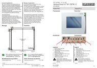
3.6 Physical Design<br />
mouse/keyboard adapter<br />
for Y cable<br />
Ethernet<br />
CANopen<br />
DVI/VGA<br />
serial port COM1<br />
24 VDC power supply<br />
protective earth<br />
heat sink for <strong>Ventura</strong> <strong>IPC</strong><br />
700/800/1000<br />
see dimensions<br />
protective earth<br />
status LEDs<br />
reset button<br />
CF card (front)<br />
CF card ejector<br />
USB1 (USB 2.5)<br />
USB2 (USB 2.5)<br />
serial port COM2<br />
E 674 GB 17<br />
07.03.2007
Hardware KUHNKE Automation<br />
3.7 <strong>Ventura</strong> <strong>IPC</strong> Power Supply and Ports<br />
3.7.1 24 VDC Power Supply<br />
3.7.2 Operative Earth<br />
3.7.3 Serial Ports "COM1 and COM2"<br />
1<br />
6<br />
2<br />
7<br />
3<br />
8<br />
4<br />
9<br />
5<br />
Only attach the unit to a 24 VDC power supply source if the source is guaranteed<br />
to meet safe extra low voltage requirements (SELV).<br />
Please use the connector from the package to attach the unit to the power<br />
supply.<br />
The admissible diameter of the cord connecting the 24 VDC power is between<br />
0.75 mm 2 and 2.5 mm 2 .<br />
Connector 2-pin, male, 2.5 mm 2<br />
Pin Function<br />
L+ Supply voltage +24 VDC<br />
L GND<br />
Connect operative earth to the protective earth conductor of the switching<br />
cabinet or the system that the PC is installed in. Use the flat plug (6.3 mm x<br />
0.8 mm) on the bottom side of the unit.<br />
The minimum cross section must be no less than 2.5 mm 2 . Try to keep the<br />
lead to the cabinet terminal as short as possible.<br />
A low-impedance earth conductor improves the dissipation of interference<br />
received via external power supply cables, signal cables or cables of peripheral<br />
units.<br />
<strong>Ventura</strong> <strong>IPC</strong> has two serial COM ports for communication with peripherals<br />
such as terminals, modems, etc. A 9-pin D-Sub connector is used to attach<br />
peripherals with a suitable cable.<br />
Connector 9-pin D-SUB, male<br />
Pin Function<br />
1 -<br />
2 TxD<br />
3 RxD<br />
4 -<br />
5 GND<br />
6 -<br />
7 CTS<br />
8 RTS<br />
9 -<br />
18 E 674 GB<br />
07.03.2007
KUHNKE Automation Hardware<br />
3.7.4 Graphics Adapter "DVI / VGA"<br />
The DVI-I adapter transfers analogue and digital monitor data (DVI-I integrated,<br />
analogue and digital) and can therefore be used for both monitors<br />
with a digital DVI port and monitors with an analogue VGA input.<br />
If a <strong>Ventura</strong> <strong>IPC</strong> touch-series monitor is attached, the cable can be up to 25<br />
m long (800x600 resolution). To bridge larger gaps, a DVI signal repeater<br />
can be installed somewhere along the line.<br />
Since the DVI port outputs VGA signals, VGA monitors can be attached using<br />
a DVI-to-VGA adapter.<br />
Pin Signal Function<br />
1 TMDS Data2- DVI data line (A)<br />
2 TMDS Data2+ DVI data line (A)<br />
3 TMDS Data2/4 shield shield<br />
4 NC*<br />
5 NC<br />
6 DDC clock (SCL) display data channel clock (I/O)<br />
7 DDC data (SDA) display data channel data (I/O)<br />
8 analogue vertical sync (VSYNC) analogue vertical sync signal (A)<br />
9 TMDS Data1- DVI data line (A)<br />
10 TMDS Data1+ DVI data line (A)<br />
11 TMDS Data1/3 shield shield<br />
12 NC<br />
13 NC<br />
14 +5V power (VCC) +5V power for DCC (A)<br />
15 Ground<br />
(return for V, Hsync and Vsync)<br />
analogue ground (GND)<br />
16 Hot plug detect<br />
17 TMDS Data 0- DVI data line (A)<br />
18 TMDS Data 0+ DVI data line (A)<br />
19 TMDS Data0/5 shield shield<br />
20 NC<br />
21 NC<br />
22 TMDS clock shield shield<br />
23 TMDS clock+ DVI clock line (A)<br />
24 TMDS clock- DVI clock line (A)<br />
C1 Analogue red (R) analogue red signal (A)<br />
C2 Analogue green (G) analogue green signal (A)<br />
C3 Analogue blue (B) analogue blue signal (A)<br />
C4 Analogue horizontal sync<br />
(HSYNC)<br />
analogue horizontal sync signal (A)<br />
C5 Analogue ground (analogue R, G,<br />
& return)<br />
analogue ground (GND)<br />
To allow the PC BIOS and operating system to properly detect and operate<br />
the DVI or CRT monitor, we recommend that you attach the monitor prior to<br />
starting the PC (automatic terminal detect).<br />
E 674 GB 19<br />
07.03.2007
Hardware KUHNKE Automation<br />
3.7.5 Interface "PS / 2"<br />
2<br />
1<br />
4<br />
3<br />
6<br />
5<br />
3.7.6 Interface "USB1","USB2"<br />
<strong>Ventura</strong> <strong>IPC</strong> features a PS / 2 interface that an external keyboard and/or an<br />
external mouse can be attached to.<br />
Connector 6-pin mini-DIN, female<br />
Pin Signal Function<br />
1 DAT (mouse) Data line (mouse)<br />
2 DAT (keyboard) Data line (keyboard)<br />
3 GND Earth<br />
4 P5VFK +5 V (fused)<br />
5 CLK (mouse) Clock line (mouse)<br />
6 CLK (keyboard) Clock line (keyboard)<br />
Shell Shield shielding<br />
To attach a keyboard or a mouse or both to the interface, a PS2 splitter (Y<br />
cable) is required.<br />
The USB adapter is the port for external peripherals such as CD-ROM<br />
drives, printers, modems or mouse and keyboard. The power supply unit for<br />
the USB peripherals supplies up to 500 mA output current and is fused by<br />
means of a maintenance-free "USB current-limiting circuit breaker". A short<br />
circuit or overload thus switches off the power supply and the "USB" status<br />
indicator lights up red.<br />
Connector type A, male<br />
Pin Signal Function<br />
1 VBUS (5 VDC) +5V (fused) for external USB port<br />
2 D- data+, USB channel 0<br />
3 D+ data-, USB channel 0<br />
4 GND GND for external USB port<br />
Shell Shield shielding<br />
The USB interfaces are made for attaching USB peripherals to. Due to the<br />
wide range of commercially available USB units and operating systems,<br />
KUHNKE cannot warrant that they will function properly.<br />
The standard demands 5m as the warranted length of line. Putting in a USB<br />
repeater you can extend lines to a maximum of 20m.<br />
Hot Plug-ready peripherals can be attached to the USB port while the PC is<br />
running.<br />
To comply with the noise immunity demanded by standard IEC 61131, the<br />
use of suitable USB cables is recommended. The accessory cables supplied<br />
by KUHNKE Automation GmbH & Co. ( 10.7.2 Accessories) are tested for<br />
compliance.<br />
Wiring of all installations should bear IT-specific needs in mind.<br />
20 E 674 GB<br />
07.03.2007
KUHNKE Automation Hardware<br />
3.7.7 Ethernet "LAN1", "LAN2"<br />
Ethernet is a commonly used, vendor-independent data transfer technology<br />
for Local Area Networks (LAN). Transfer rates are 10 million or 100 million<br />
bits per second (Mbps). Refer to standard IEEE802.3 to find specifications<br />
for the RJ 45 jack used in this device.<br />
Connector RJ 45 (female):<br />
Pin Signal Function<br />
1 TD + Transmit +<br />
2 TD - Transmit -<br />
3 RD + Receive +<br />
4 - -<br />
5 - -<br />
6 RD - Receive -<br />
7 - -<br />
8 - -<br />
Assuming you wish to attach <strong>Ventura</strong> <strong>IPC</strong> to a second network component<br />
(PC �� PC), but there is no uplink port, you can use a crossover cable to<br />
still establish the connection.<br />
A crossover cable X-links the two Receive and Transmit lines of the two<br />
interconnecting network components.<br />
E 674 GB 21<br />
07.03.2007
Hardware KUHNKE Automation<br />
3.7.8 Fieldbus Interface "BUS1" as CANopen Port<br />
1<br />
6<br />
2<br />
7<br />
3<br />
8<br />
4<br />
9<br />
5<br />
3.8 <strong>Ventura</strong> <strong>IPC</strong> Controls<br />
3.8.1 "RESET" Button<br />
RUN<br />
STOP<br />
ERROR<br />
HDD<br />
BUS<br />
DVI<br />
USB<br />
RESET<br />
<strong>Ventura</strong> <strong>IPC</strong> is a control PC with an integrated CANopen fieldbus interface.<br />
To connect to a CANopen network, attach a 9-pin female Sub-D connector<br />
to the male Sub-D CAN port on the unit. Its address is set at the configuration<br />
stage.<br />
Connector 9-pin D-SUB, male<br />
Pin Function<br />
1 -<br />
2 CAN-L<br />
3 CAN-GND<br />
4 -<br />
5 -<br />
6 -<br />
7 CAN-H<br />
8 -<br />
9 -<br />
Housing frame ground (cable shield)<br />
Please note that the CAN BUS must be properly terminated at both ends of<br />
the bus cable.<br />
For details on how to install the bus cable, on shielding, connectors, bus<br />
nodes and bus termination refer to instruction manual E 615 GB "CANopen“.<br />
The Reset button is located on the front of the device, underneath the <strong>Ventura</strong><br />
<strong>IPC</strong>'s status indicators. To avoid unintended actuation, you need a tool<br />
to operate it.<br />
Use a pointed object (pen, screwdriver) to press the Reset button. Pressing<br />
the button performs a hardware reset. The <strong>IPC</strong> reboots (cold boot).<br />
22 E 674 GB<br />
07.03.2007
KUHNKE Automation Hardware<br />
3.9 Storage Media (Removable Disk)<br />
3.9.1 Compact Flash Card Slot "CF-CARD"<br />
ejector mechanism<br />
Look at the back of the <strong>Ventura</strong> <strong>IPC</strong> housing to find the Compact Flash slot.<br />
The card stores the monitor program and the user program. Push the CF<br />
card into the slot until it is flush with the housing. You need a narrow or pointed<br />
object (screwdriver, pen) to actuate the ejector mechanism. You cannot<br />
remove the CF card while <strong>Ventura</strong> <strong>IPC</strong> is in the switching cabinet.<br />
Model variants <strong>Ventura</strong> <strong>IPC</strong> 300 and <strong>Ventura</strong> <strong>IPC</strong> 300 + feature a second<br />
compact flash slot at the front of the unit. The second CF card can be used<br />
for storing extra data, e.g. recipes.<br />
The ejector will mechanically push out the card until you can pull it out with<br />
your fingers. When you slot in the card, the ejector mechanism audibly<br />
snaps in.<br />
CompactFlash cards are susceptible to electrostatic discharge (ESD). Improper<br />
handling may lead to temporary or complete failure.<br />
Please take account of the instructions on how to handle memory cards.<br />
The compact flash card (CF card) is a non-volatile memory. The data stored<br />
on it will be retained even in the event of a power failure.<br />
We recommend to only use CF cards designed for industrial applications<br />
because these cards have an extended temperature range and can be rewritten<br />
more often.<br />
Compact flash cards (CF cards) of various volume capacities are sold as separate<br />
accessory options.<br />
3.9.2 Compact Flash Card Slot "CF-CARD"<br />
ejector mechanism<br />
3.10 LED Indicators, <strong>Ventura</strong> <strong>IPC</strong><br />
3.10.1 Status LEDs<br />
Look at the front of the <strong>Ventura</strong> <strong>IPC</strong> 300 housing to find a second Compact<br />
Flash slot which allows you to operate an additional storage volume of compact<br />
flash type I.<br />
CompactFlash cards are susceptible to electrostatic discharge (ESD).<br />
Improper handling may lead to temporary or complete failure.<br />
Please take account of the instructions on how to handle memory cards.<br />
Name LED Description<br />
E 674 GB 23<br />
07.03.2007
Hardware KUHNKE Automation<br />
RUN<br />
STOP<br />
ERROR<br />
HDD<br />
BUS<br />
DVI<br />
USB<br />
RUN OFF<br />
GREE<br />
N<br />
STOP OFF<br />
RED<br />
ERROR OFF<br />
RED<br />
HDD OFF<br />
YEL-<br />
LOW<br />
BUS OFF<br />
YEL-<br />
LOW<br />
OFF<br />
YEL-<br />
LOW<br />
DVI OFF<br />
YEL-<br />
LOW<br />
USB OFF<br />
RED<br />
PLC program not loaded, not started<br />
PLC program runs cyclically<br />
PLC program runs cyclically<br />
PLC program not loaded, not started<br />
No system error<br />
Operative controller problem<br />
Shows that the CF card is being accessed<br />
Data traffic on the fieldbus<br />
No function<br />
DVI display active<br />
USB station short circuit<br />
24 E 674 GB<br />
07.03.2007
KUHNKE Automation Hardware<br />
3.11 External Elements, <strong>Ventura</strong> <strong>IPC</strong> + Hardware PLC<br />
Industry PC connectors<br />
mouse/keyboard<br />
status LEDs<br />
<strong>IPC</strong> reset button<br />
Ethernet<br />
CF card (front)<br />
field bus interface 1<br />
CF card ejector<br />
DVI/VGA<br />
USB<br />
serial interfaces<br />
COM1<br />
COM2<br />
<strong>IPC</strong> power supply<br />
heat sink for<br />
<strong>Ventura</strong> <strong>IPC</strong> 700/800/1000<br />
see dimensions<br />
protective earth<br />
Hardware PLC<br />
connectors<br />
status LEDs<br />
PLC hardware<br />
reset button<br />
field bus interface 2<br />
field bus interface 3<br />
digital combi I/Os<br />
RS 232<br />
power supply to hardware<br />
PLC<br />
E 674 GB 25<br />
07.03.2007
Hardware KUHNKE Automation<br />
3.12 Power Supply and Interfaces, PLC Hardware <strong>Ventura</strong>+<br />
3.12.1 24 VDC Power Supply<br />
3.12.2 Operative Earth<br />
Only attach the unit to a 24 VDC power supply source if the source is guaranteed<br />
to meet safe extra low voltage requirements (SELV).<br />
Please use the connector from the package to attach the unit to the power<br />
supply.<br />
The admissible diameter of the cord connecting the 24 VDC power is between<br />
0.2 mm 2 and 2.5 mm 2 .<br />
Connector 2-pin, male, 2.5 mm 2<br />
Pin Function<br />
L+ Supply voltage +24 VDC<br />
L GND<br />
Connect <strong>Ventura</strong>'s operative earth connector to the protective earth conductor<br />
of the cabinet or system / machine element. Use the flat plug (6.3 mm x<br />
0.8 mm) at the back of the unit.<br />
The minimum cross section must be no less than 2.5 mm 2 . Try to keep the<br />
lead to the earthing terminal as short as possible.<br />
A low-impedance earth conductor improves the dissipation of interference<br />
received via external power supply cables, signal cables or cables of peripheral<br />
units.<br />
3.12.3 Fieldbus Interface "BUS2" as CANopen Port<br />
1<br />
6<br />
2<br />
7<br />
3<br />
8<br />
4<br />
9<br />
5<br />
Hardware PLC <strong>Ventura</strong> <strong>IPC</strong> + is an embedded controller with integrated<br />
CANopen fieldbus interface. To connect to a CANopen network, attach a 9pin<br />
female Sub-D connector to the male Sub-D CAN port on the unit. Its address<br />
is set at the configuration stage.<br />
Connector 9-pin D-SUB, male<br />
Pin Function<br />
1 -<br />
2 CAN-L<br />
3 CAN-GND<br />
4, 5, 6 -<br />
7 CAN-H<br />
8, 9 -<br />
Housing frame ground (cable shield)<br />
Please note that the CAN BUS must be properly terminated at both ends of<br />
the bus cable.<br />
For details on how to install the bus cable, on shielding, connectors, bus<br />
nodes and bus termination refer to instruction manual E 615 GB "CANopen“.<br />
26 E 674 GB<br />
07.03.2007
KUHNKE Automation Hardware<br />
3.12.4 Fieldbus Interface "BUS3" as PROFIBUS Port<br />
5<br />
9<br />
4<br />
8<br />
3<br />
7<br />
2<br />
6<br />
1<br />
3.12.5 Digital Combi I/O "DI/DO"<br />
1<br />
2<br />
4<br />
Hardware PLC <strong>Ventura</strong> <strong>IPC</strong> + can be optionally equipped with a PROFIBUS<br />
DP master port. To connect to a bus, attach a 9-pin male Sub-D PROFIBUS<br />
connector to the female PROFIBUS port on the unit.<br />
Run the bus configuration utility to set the network's baud rate and address,<br />
then transfer the hardware parameters to the hardware PLC. It is not necessary<br />
to change any bus parameter settings at the device hardware.<br />
Connector 9-pin D-SUB, male<br />
Pin Function<br />
1 (attached to housing frame)<br />
2 -<br />
3 RxD/TxD-P (Data +)<br />
4 -<br />
5 DGnd<br />
6 VP (+5 V power, max. 100 mA)<br />
7 -<br />
8 RxD/TxD-N (Data -)<br />
9 -<br />
Housing frame ground (connected with pin 1)<br />
Attach the cable shield to the connector housing.<br />
Please note that the PROFIBUS must be properly terminated at both ends of<br />
the bus cable. The PROFIBUS jack of hardware PLC <strong>Ventura</strong> <strong>IPC</strong> + supplies<br />
the required voltage.<br />
For details on how to install the bus cable, on shielding, connectors, bus<br />
nodes and bus termination refer to instruction manual E 611 GB "PROFI-<br />
BUS-DP“.<br />
Hardware PLC <strong>Ventura</strong>+ features 5 digital combi I/Os "DI/DO 0 ... 4" which<br />
can be set to act as inputs, special-function inputs or as outputs.<br />
Connector 5-pin, male, 2.5 mm 2<br />
Pin Function<br />
Input Output (short-circuit-proof)<br />
0 Interrupt A1 track counter, 24 VDC/0.5 A<br />
1 Interrupt B1 track - 24 VDC/0.5 A<br />
2 Interrupt A2 track counter, 24 VDC/0.5 A<br />
3 Interrupt A3 track - 24 VDC/0.5 A<br />
4 Interrupt Ref track - -<br />
If used as inputs, DI/DO 0 to DI/DO 4 are marked by their very short rising<br />
delay. User programs can read them just like normal inputs. To be able to<br />
immediately react to events, they are capable of requested processor interrupts.<br />
LEDs lighting up green show that there is either an input signal or that the<br />
output is active. Active outputs can be checked via the input address.<br />
Optional<br />
E 674 GB 27<br />
07.03.2007
Hardware KUHNKE Automation<br />
3.12.6 Serial RS 232 Interface<br />
5<br />
9<br />
4<br />
8<br />
3<br />
7<br />
22<br />
6<br />
1<br />
Combi I/Os DI/DO 0 and DI/DO 2 are designed to also act as event counters<br />
up to 10 kHz. If combined with a 24V incremental encoder, these combi I/Os<br />
also provide A, B, Ref counter functions.<br />
Their actual function is set at the configuration stage.<br />
The maximum nominal current of every combi I/O output is 0.5 A.<br />
If a combi I/O is used as an output, mind that no external input signal must<br />
go through that port at the same time.<br />
The main practical use of the RS 232 port is to attach an external programming<br />
device to it. However, you could also use it for exchanging data with<br />
dialog terminals, PCs and other such devices.<br />
Connector 9-pin D-SUB, female<br />
Pin Function<br />
1 -<br />
2 TxD<br />
3 RxD<br />
4 -<br />
5 GND<br />
6 -<br />
7 -<br />
8 -<br />
9 -<br />
Housing shielding<br />
If the interface is used for communication with a CoDeSys programming<br />
system, choose menu item "Communication Parameters" to set its baud rate<br />
to 38400 baud.<br />
The normal programming cable from the accessories range connects the<br />
<strong>Ventura</strong>+ hardware PLC with the programming device.<br />
Part number 691.151.09<br />
Length 3.0 m<br />
Assignment 1 : 1<br />
28 E 674 GB<br />
07.03.2007
KUHNKE Automation Hardware<br />
3.13 <strong>Ventura</strong>+ Hardware PLC Controls<br />
3.13.1 "RESET" Button<br />
RUN<br />
STOP<br />
ERROR<br />
BUS2<br />
BUS3<br />
RESET<br />
3.14 <strong>Ventura</strong> Indicators<br />
3.14.1 Status LEDs<br />
RUN<br />
STOP<br />
ERROR<br />
BUS2<br />
BUS3<br />
RESET<br />
The Reset button is located on the front of the device, underneath the <strong>Ventura</strong>'s<br />
status indicators. The reset / cold boot will affect the <strong>Ventura</strong>+ hardware<br />
PLC only, but not the PC.<br />
To avoid it being pushed unintentionally, the Reset button can be operated<br />
using a pointed object (pen, screwdriver) only.<br />
Label LED Description<br />
RUN OFF<br />
GREE<br />
N<br />
STOP OFF<br />
RED<br />
ERROR OFF<br />
RED<br />
BUS2 OFF<br />
YEL-<br />
LOW<br />
BUS3 OFF<br />
YEL-<br />
LOW<br />
FLASHI<br />
NG<br />
PLC program not loaded, not started<br />
PLC program runs cyclically<br />
PLC program runs cyclically<br />
PLC program not loaded, not started<br />
No system error<br />
Operative controller problem<br />
Ready<br />
OK, all stations connected to bus<br />
Warning, station missing<br />
Flash code imitates address of missing station<br />
E 674 GB 29<br />
07.03.2007
Hardware KUHNKE Automation<br />
3.15 Error Codes<br />
RUN<br />
STOP<br />
ERROR<br />
HDD<br />
BUS<br />
DVI<br />
USB<br />
RESET<br />
LEDs "RUN“, "STOP“ and "ERROR“ exclusively refer to functions of soft-<br />
PLC CoDeSys SP. If CoDeSys SP if off these LEDs have no function.<br />
LEDs "RUN" and "STOP", PLC op. modes<br />
RUN STOP Operating mode<br />
Off On PLC program not loaded<br />
Off On PLC program loaded but not started<br />
On Off PLC program loaded and started<br />
Flashing On PLC program loaded and started but stopped at<br />
breakpoint (DEBUG)<br />
LED "ERROR"<br />
Whereas LED "ERROR" indicates serious operative problems, it is not indicative<br />
of any PLC program errors. The following classify a serious operative<br />
problems: watchdog, low voltage, short circuit.<br />
If applicable, these problems are indicated by KUHNKE's well-known flash<br />
codes. Every flash pulse lasts 500 ms (250 ms on, 250 ms off), every flash<br />
sequence consists of n flash pulses (e.g. watchdog: n = 3), flash sequences<br />
are interrupted by 1 s breaks (off).<br />
30 E 674 GB<br />
07.03.2007
KUHNKE Automation Hardware<br />
4 Installation<br />
4.1 Flange Plate Installation<br />
Control PC <strong>Ventura</strong> <strong>IPC</strong> is designed for front panel installation. However,<br />
you can also choose to install the unit on any other even surface using the<br />
flange fitting. Please take note of the admissible ambient conditions during<br />
storage and operation as summarised in the Technical Data tables.<br />
A flange for installing the device at the rear wall of a switching cabinet or on<br />
any other even surface can be ordered as a separate accessory option. The<br />
<strong>Ventura</strong> 800 / 1000 series has the flange fitting as a component part of the<br />
housing. In these cases, the flange plate need not be ordered separately.<br />
4.1.1 To Install the Screw Plate Adapter (<strong>Ventura</strong> <strong>IPC</strong> 300 / 700)<br />
4.1.2 To Install the Device<br />
• Use screws (2) to attach the flange plate (1) to the back of the unit.<br />
• Drill holes into the mounting surface as shown on the illustration.<br />
• Turn all but approx. 5 mm of the screws into the holes drilled into the<br />
mounting surface.<br />
• Put on the device and push down.<br />
• Turn in the screws until tight.<br />
Please remember that the plate and screws must not only be able to sustain<br />
the weight of the device but also that of the cables.<br />
E 674 GB 31<br />
07.03.2007
Hardware KUHNKE Automation<br />
4.2 Mounting on Top-hat Rail (<strong>Ventura</strong> <strong>IPC</strong> 300 / 700)<br />
4.2.1 To Attach the Rail Adapter to the Device<br />
• Use screws (2) to attach snap-on adapter (1) to the back of the unit.<br />
4.2.2 To Attach the Device to the Top-hat Rail<br />
• Place the device on the upper top-hat rail guide, holding it at a slant.<br />
• Tip the device down onto the top-hat rail until the bracket of the adapter<br />
snaps onto the bottom top-hat rail guide.<br />
4.2.3 To Remove the Device from the Top-hat Rail<br />
• Pull down the strap at the bottom side of the device. Use a flat screwdriver<br />
and turn it slightly.<br />
• This will unlock the mechanism holding the unit firmly in place on the<br />
top-hat rail.<br />
• You can now remove the device.<br />
32 E 674 GB<br />
07.03.2007
KUHNKE Automation Software<br />
5 Start-up<br />
Various variants of the <strong>Ventura</strong> industial PC (<strong>IPC</strong>) are available. For the exact<br />
system configuration of your device, please refer to the name plate and<br />
the coded part number on it.<br />
To allow the BIOS and operating system to properly detect the DVI or CRT<br />
monitor at boot-up, we recommend that you attach the monitor prior to attaching<br />
the device to the power supply.<br />
Danger of damage to the unit!<br />
If the device was exposed to condensation, allow it to rest for about 12 hours<br />
before you start to use it.<br />
5.1 Installing CoDeSys on the Programming PC<br />
5.1.1 CoDeSys Target Installation<br />
To install the CoDeSys software on your programming<br />
PC:<br />
• Select CoDeSys...exe either from Windows Explorer or via 'Run' from<br />
the Windows Start menu.<br />
• Run the program.<br />
• The CoDeSys installer runs to request your preferred settings and install<br />
the application in the target system.<br />
To obtain an installation copy of the CoDeSys programming system either<br />
ask for the up-to-date CD-ROM 'Software & Information, E 627 D / GB' or<br />
browse for www.3s-software.com and find the download page of that company<br />
To create a CoDeSys project for target system "<strong>Ventura</strong> <strong>IPC</strong>", you must install<br />
the Target Support Package (TSP) "<strong>Ventura</strong>CE_TV.tnf" prior to running<br />
the program by running the installer called InstallTarget.<br />
A TSP contains all configuration and extension files required to use an application<br />
for operating a certain controller (target system).<br />
A configuration includes the code generator, the memory layout, the set of<br />
functions provided by the controller and the I/O modules.<br />
The libraries, gateway drivers, error and ini files for the PLC browser etc. are<br />
also installed.<br />
• Run the target installer delivered with your CoDeSys package.<br />
• Click on "Open" to open the folder containing TSP "KUHNKE PC Control<br />
<strong>Ventura</strong>", then choose "<strong>Ventura</strong>CE_TV.tnf".<br />
• Click to select "KUHNKE PC Control <strong>Ventura</strong>" and "Install" it.<br />
E 674 GB 33<br />
07.03.2007
Software KUHNKE Automation<br />
5.2 CoDeSys Programming PC Setup<br />
5.2.1 Ethernet Connections of <strong>Ventura</strong> <strong>IPC</strong><br />
5.2.2 Programming PC Interface Setup<br />
Following successful installation, "KUHNKE PC Control <strong>Ventura</strong>" appears in<br />
column "Installed target systems. The programming system can now access<br />
the <strong>Ventura</strong> controller.<br />
• To directly connect the <strong>IPC</strong> with the programming PC, please use a<br />
CAT5 crossover cable.<br />
• To operate the <strong>Ventura</strong> <strong>IPC</strong> in a network, please use a CAT5 patch<br />
cable.<br />
• CoDeSys communication should go through the <strong>Ventura</strong> <strong>IPC</strong>'s<br />
LAN2 port if at all possible.<br />
• Establish the connection before turning on the <strong>IPC</strong>'s 24 V power<br />
supply.<br />
Network connection<br />
No settings should have to be made or changed to program the <strong>IPC</strong> via a<br />
network.<br />
Windows 98, direct connection<br />
• Go to Windows Start and choose<br />
Start – Settings – Control Panels: "Network" – pick "TCP/IP" from the<br />
list, then "Properties".<br />
• Go to tab "IP address", choose "Set IP address" and enter any IP address<br />
as appropriate,<br />
e.g.: "169.254.112.85", subnet mask "255.255.255.0".<br />
34 E 674 GB<br />
07.03.2007
KUHNKE Automation Software<br />
Windows XP, direct connection<br />
• Go to Windows Start and choose<br />
Start – Settings – Network Connections: pick LAN connection from list,<br />
Properties<br />
• Go to tab "General", find the list of elements, choose "Internet protocol<br />
(TCP/IP)" and click on Properties.<br />
• Still on tab "General" choose "Use this IP address" and enter any IP<br />
address as appropriate,<br />
e.g.: "169.254.112.85", subnet mask "255.255.255.0"<br />
A direct connection requires the "File and printer release" to be ticked and a<br />
firewall, if any, to be disabled at least for the time of this connection.<br />
5.2.3 CoDeSys Target System Setting on the Programming PC<br />
• Run PLCWinCE on the <strong>Ventura</strong> <strong>IPC</strong><br />
(Start – Programs – KUHNKE – PLCWinCE)<br />
• Create a new CoDeSys project and choose "KUHNKE PC Control <strong>Ventura</strong>"<br />
as its target system<br />
• Choose "Online – Communication Parameters" to set up a TCP/IP connection<br />
using the IP address you previously specified for the <strong>Ventura</strong><br />
<strong>IPC</strong>.<br />
E 674 GB 35<br />
07.03.2007
Software KUHNKE Automation<br />
6 Windows ® XP Embedded<br />
Windows ® XP Embedded is based on the functionality of Windows ® XP Professional<br />
plus that it contains a set of predefined system configurations and<br />
more than 10,000 separate components that hardware developers can<br />
choose from. The space required by the installation (i.e., its footprint) can be<br />
minimised to make the operating system fit onto flash media.<br />
Windows ® XP Embedded is marked by its high level of reliability, safety and<br />
performance. It runs even on "small" x86 systems.<br />
Windows ® XP Embedded thus provides all properties for perfect interaction<br />
with industrial PCs to be trusted with industrial control tasks while still having<br />
the whole range of Windows ® communication and software features at hand.<br />
36 E 674 GB<br />
07.03.2007
KUHNKE Automation Software<br />
6.1 Components<br />
6.1.1 General Data<br />
Operating system Windows XP embedded SP1<br />
Current image version 1.0<br />
Memory requirements approx. 512 Mb<br />
Graphical user interface Explorer Shell<br />
Language English, German<br />
6.1.2 Breakdown of Key Components of the Windows<br />
® XP embedded Image<br />
Development / runtime environments / interfaces<br />
COM<br />
EWF<br />
Jet database engine ports (ODBC, OLEDB, DAO)<br />
ODBC interface<br />
Applications<br />
Console<br />
Internet Explorer 6<br />
Netmeeting<br />
Notepad<br />
On-Screen Keybord<br />
Windows Explorer<br />
Windows Media Player<br />
Network<br />
Network support (TCP/IP)<br />
File release<br />
Remote data transfer<br />
DHCP client<br />
DNS client<br />
Network Setup Wizard<br />
Remote Desktop<br />
System administration / system tools<br />
Event Log, Service Control Manager, Computer Management<br />
Check Disk<br />
Enhanced Write Filter<br />
Registry Editor<br />
System locals / English and German keyboard layouts<br />
Control Panels<br />
Task Scheduler<br />
Support of peripherals<br />
USB printer<br />
Touch<br />
Modem<br />
USB storage media<br />
Services<br />
Indexing Service<br />
Messenger<br />
6.1.3 XP embedded File System<br />
The <strong>Ventura</strong> <strong>IPC</strong> hosts the operating system on a CF card. It uses the NTFS<br />
file system (New Technology File System). The memory card resides in the<br />
system just like a hard disk. It therefore does not classify as a "removable<br />
disk" and must not be started up. The card is not "Hot Plug"-ready.<br />
E 674 GB 37<br />
07.03.2007
Software KUHNKE Automation<br />
6.2 Tools<br />
6.2.1 <strong>Ventura</strong> touch Calibration<br />
6.2.2 Temperature Monitor<br />
To calibrate and configure the <strong>Ventura</strong> touch screen monitor, run the "hwincal"<br />
application. If you chose the "Default Installation" option, browse the<br />
Start menu for folder "Programs / Touch / hwincal".<br />
For further information on how to calibrate <strong>Ventura</strong> touch refer to instruction<br />
manual E 675 GB "<strong>Ventura</strong> touch".<br />
Tool "Show<strong>Ventura</strong>Temp" takes readings of the temperature sensors integrated<br />
in the CPU and heat sink of <strong>Ventura</strong> <strong>IPC</strong> 700 and outputs them to the<br />
screen.<br />
Show<strong>Ventura</strong>Temp is freeware. Browse the <strong>Ventura</strong> <strong>IPC</strong> memory for folder<br />
'C/Program Files/<strong>Ventura</strong> Tool'.<br />
• To use the tool run "Show<strong>Ventura</strong>Temp.exe" located in folder<br />
'C/Program Files/<strong>Ventura</strong> Tool'.<br />
• The on-screen monitor is displayed.<br />
• Adapt the scales to the readings or use the "Auto" function.<br />
The temperature monitor option is not supported by <strong>Ventura</strong> <strong>IPC</strong> 300.<br />
38 E 674 GB<br />
07.03.2007
KUHNKE Automation Software<br />
6.2.3 OPC Server<br />
6.3 IPHelper<br />
6.3.1 USB Memory Stick<br />
A standard installation normally installs the OPC Server and makes it available<br />
to every <strong>Ventura</strong> <strong>IPC</strong>. We are still taking the CoDeSys RTE as an example<br />
of how to install and configure the OPC Server.<br />
The "IPhelper" tool display the current settings and IP addresses of the Ethernet<br />
interfaces. To toggle between LAN1 and LAN2 information, click on<br />
the picture of the <strong>Ventura</strong> <strong>IPC</strong>.<br />
Windows XP automatically detects normal plug & play USB memory sticks<br />
and card readers, knows that they are removable disks and adds new drives<br />
to the Explorer. The operating system displays a Desktop message to that<br />
effect.<br />
To retain the formatting of removable disks attached to the USB port, it is<br />
recommended to always use "safe hardware remove" to unplug such devices<br />
from the port.<br />
To display that dialog, click on icon located on the status bar.<br />
E 674 GB 39<br />
07.03.2007
Software KUHNKE Automation<br />
6.3.2 Create New SID<br />
When the <strong>Ventura</strong> <strong>IPC</strong> devices are produced a clone of the tested memory<br />
image is copied to all the devices made afterwards. This method ensures<br />
that the software of all devices is perfectly identical.<br />
Whereas this is a fast and efficient approach, it also entails that all devices<br />
have the same SID (computer security identifier) and computer name which<br />
some networks may have problems with.<br />
To avoid these problems there is a tool called "NewSID" whose job it is to give<br />
the system a unique new SID.<br />
Browse the <strong>Ventura</strong> <strong>IPC</strong> memory for folder 'C/Program Files/<strong>Ventura</strong> Tool' to<br />
locate the NewSID utility.<br />
• To use the tool run "newsid.exe" located in folder 'C/Program Files/<strong>Ventura</strong><br />
Tool'.<br />
• Readme file "NewSIDReadme.txt" contains further information on the<br />
tool.<br />
It may take a couple of minutes until a new SID has been assigned.<br />
40 E 674 GB<br />
07.03.2007
KUHNKE Automation Software<br />
6.3.3 UltraVNC Remote Control Option<br />
UltraVNC allows you to view the contents of a remote PC's Desktop and to<br />
seize control of the PC you are monitoring.<br />
UltraVNC is freeware. Browse the <strong>Ventura</strong> <strong>IPC</strong> memory for folder<br />
'C/Program Files/<strong>Ventura</strong> Tool / install' for an installation copy of the software.<br />
To install run file 'UltraVNC-101-Setup.exe'.<br />
Connect to the PC<br />
• Set up a network connection between the <strong>Ventura</strong> <strong>IPC</strong> and the monitoring<br />
PC.<br />
• Turn to the <strong>Ventura</strong> <strong>IPC</strong>, run 'UltraVNC Server' and adapt the settings<br />
as appropriate. Remember to specify a password to protect the connection<br />
against attacks.<br />
• Turn to the monitoring PC, run 'UltraVNC Viewer' and enter the "VNC<br />
Server" port you are using. To check the connection settings, go back to<br />
the <strong>Ventura</strong> <strong>IPC</strong> and display the 'LAN Status' screen.<br />
• Click on 'Connect' and enter the password you specified on the <strong>Ventura</strong><br />
<strong>IPC</strong>.<br />
• You will see a copy of <strong>Ventura</strong> <strong>IPC</strong>'s screen. Depending on your settings<br />
you will be able to take actions as appropriate.<br />
E 674 GB 41<br />
07.03.2007
Software KUHNKE Automation<br />
6.4 File Transfer<br />
The UltraVNC tool has a special dialog dedicated to controlling file transfer<br />
operations.<br />
• Click on the "Open File Transfer" button located on UltraVNC's control<br />
bar.<br />
The "File Transfer" dialog is displayed showing the complete folder structures<br />
of the two interconnecting PCs. There are various buttons for sending,<br />
receiving or deleting files.<br />
42 E 674 GB<br />
07.03.2007
KUHNKE Automation Software<br />
6.5 <strong>Ventura</strong> SlotPLC Gateway Driver<br />
6.5.1 Installation<br />
Before you can communicate with the <strong>Ventura</strong> SlotPLC via the DPRAM you<br />
must first install the appropriate driver in <strong>Ventura</strong> <strong>IPC</strong> +.<br />
At the time of delivery, installer SetupDPRamISA8K.exe is located in folder<br />
C:\Program Files\<strong>Ventura</strong> Tools\Install of your <strong>Ventura</strong>+.<br />
SetupDPRamISA8K.exe copies the gateway driver, i.e. DPRamISA.dll and<br />
Drv<strong>Kuhnke</strong>ISA.dll, to<br />
WINDOWS/SYSTEM32 and enters Drv<strong>Kuhnke</strong>ISA.dll into the registry.<br />
• Pick "Run" from the Windows Start menu.<br />
• Click on "Browse".<br />
• Navigate to C:\Program Files\<strong>Ventura</strong> Tools\Install and choose "SetupDPRamISA8K.exe".<br />
• Click on "OK" to actually run the installer.<br />
6.5.2 To verify correct installation of the <strong>Ventura</strong> SlotPLC gateway drivers<br />
The following drivers will be added to your Windows\System32 folder during<br />
Target installation.<br />
• DPRamISA.dll<br />
• Drv<strong>Kuhnke</strong>ISA.dll<br />
Drv<strong>Kuhnke</strong>ISA.dll is the one entered into the Registry. To check do the following:<br />
• From WINDOWS' Start menu choose Run and enter "regedit".<br />
• Browse for folder <strong>Kuhnke</strong>ISA645 \HKEY_LOCAL_MACHINE\.....(see<br />
status line in the figure below).<br />
For further information on the <strong>Ventura</strong>+ SlotPLC refer to instruction manual<br />
E 697 GB " <strong>Ventura</strong> SlotPLC".<br />
E 674 GB 43<br />
07.03.2007
Software KUHNKE Automation<br />
7 Windows ® CE.NET<br />
7.1.1 Windows CE.NET File System<br />
The Windows ® CE.NET operating system provides substantial benefits for<br />
industrial applications.<br />
• Real-time capability<br />
• Low memory requirements<br />
• Large selection of drivers<br />
• Various communication ports<br />
• Integrated tools<br />
• Flexible Platform Builder for image compilations<br />
• Low-cost runtime licences<br />
The <strong>Ventura</strong> <strong>IPC</strong> hosts the operating system on a CF card. It uses the FAT<br />
file system " File Allocation Table".<br />
The memory card resides in the system just like a hard disk. It therefore<br />
does not classify as a "removable disk" and must not be started up. The card<br />
is not "Hot Plug"-ready.<br />
44 E 674 GB<br />
07.03.2007
KUHNKE Automation Software<br />
7.1.2 Components<br />
Table of key CE image components<br />
(based on CE 4.2)<br />
Application End User<br />
ActiveSync<br />
CAB File Installer/Uninstaller<br />
Help<br />
Terminal Emulator<br />
WordPad<br />
Application and Services Development<br />
.NET Compact Framework<br />
.NET Compact Framework 1.0<br />
OS Dependencies for .NET Compact Framework 1.0<br />
Smart Device Authentication Utility<br />
Active Template Library (ALT)<br />
CLibraries and Runtimes<br />
DCOM<br />
Microsoft Foundation Classes (MFC)<br />
Standard SDK for Windows CE.NET<br />
XML<br />
Communication Services and Networking<br />
Networking – Local Area Network (LAN)<br />
Networking – Wide Area Networking (WAN)<br />
FTP Server<br />
Web Server (HTTPD)<br />
Core OS Services<br />
Remote Display Application<br />
Serial Port Support<br />
USB Host Support<br />
Fonts<br />
Arial<br />
Courier New<br />
Symbol<br />
Tahoma<br />
Times New Roman<br />
Verdana<br />
Webdings<br />
Wingding<br />
International<br />
Multilingual User Interface (MUI)<br />
National Language Support (NSL)<br />
Internet Client Services<br />
Internet Explorer 6.0 for Windows CE<br />
Scripting<br />
Multimedia Technologies<br />
WMV and MPEG-4 Streaming<br />
Waveform Audio<br />
MP3 Codec<br />
WMA Codec<br />
WMA Voice Codec<br />
Windows Media Player<br />
Security<br />
Authentication Services (SSPI)<br />
Kerberos<br />
NTLM<br />
Schannel (SSL/TLS)<br />
Cryptography Services (CryptoAPI 1.0)<br />
Certificates (CryptoAPI 2.0)<br />
Diffie-Hellman/DSS Provider<br />
Smart Card Encryption Provider<br />
Shell and User Interface<br />
Software Input Panel<br />
E 674 GB 45<br />
07.03.2007
Software KUHNKE Automation<br />
7.1.3 <strong>Ventura</strong> touch Calibration<br />
7.1.4 Running Applications<br />
When you run your <strong>Ventura</strong> <strong>IPC</strong> on a CE platform for the first time, touch<br />
screen calibration will be performed automatically (one-off Autorun). Please<br />
follow the on-screen instructions. Afterwards you can start using your <strong>Ventura</strong><br />
touch.<br />
To recalibrate the touch screen at any later time, manually run HCECAL.exe.<br />
On KUHNKE <strong>Ventura</strong> <strong>IPC</strong> systems, the program is located in Start menu folder<br />
"Programs / <strong>Kuhnke</strong>".<br />
For further information on how to calibrate <strong>Ventura</strong> touch refer to instruction<br />
manual E 675 GB "<strong>Ventura</strong> touch".<br />
Autorun<br />
To automatically run an application on the <strong>Ventura</strong> <strong>IPC</strong>, the easiest way is to<br />
add the relevant link to the 'Autorun' folder. To locate the Autorun subfolder,<br />
browse the CE volume's root directory (Explorer: "\storage card\autorun") for<br />
it.<br />
A link ("LNK" files) contains the command line that runs the corresponding<br />
application. To handle a link:<br />
• run any ASCII editor (e.g. "notepad.exe") on the host computer to edit<br />
the link file, then upload it to <strong>Ventura</strong> <strong>IPC</strong>;<br />
• run Microsoft WordPad ("pword.exe") installed on the <strong>Ventura</strong> <strong>IPC</strong> to edit<br />
the link file as appropriate.<br />
Link format<br />
gen. xy#"\"<br />
e.g. 31#"\storage card\3s\plcwince.exe"<br />
"xy" is the decimal number of characters after "#", including the quotation<br />
marks. Quotation marks are required only if the path or file name contains<br />
white space as in the example above.<br />
Do not terminate the command line with CR/LF!<br />
Do not use uppercase letters!<br />
At the time of delivery, subfolder "storage card\kuhnke\sm" contains a couple<br />
of .LNK files which can be copied, renamed or edited.<br />
Start menu and Desktop links<br />
An approach similar to using Autorun is to paste links to the Start menu or<br />
onto the Desktop:<br />
Links to be added to the Start menu will be stored in subdirectory "\storage<br />
card\kuhnke\sm".<br />
Links to be placed on the Desktop will be stored in subdirectory "\storage<br />
card\kuhnke\dt".<br />
46 E 674 GB<br />
07.03.2007
KUHNKE Automation Software<br />
7.1.5 OPC Server<br />
7.1.6 Printers<br />
7.1.7 USB Memory Stick<br />
7.1.8 Remote Control Option<br />
The <strong>Ventura</strong> <strong>IPC</strong> CE image contains all components required for operating a<br />
USB printer. All PostScript Level 1, 2 or 3 printers are supported.<br />
To print from <strong>Ventura</strong> with a CE platform, choose LPT1 as the printer port -<br />
the appropriate USB port will be allocated to this logical interface.<br />
A USB memory stick can be plugged into any available USB port. This mass<br />
storage medium is supported by the standard CE image. Whereas the CE<br />
operating system shows the memory stick as a separate volume in the CE<br />
Explorer, it will not output any other message, e.g. to the Desktop.<br />
After plugging in a memory stick, allow the CE Explorer about 30s to detect<br />
and show it as a "hard disk" and, after unplugging it, about 5s to remove it<br />
again.<br />
<strong>Ventura</strong> <strong>IPC</strong> CE system packages contain a utility program called 'Remote-<br />
Display' which allows another network computer to seize control over the<br />
<strong>Ventura</strong> <strong>IPC</strong> system. Prerequisites are to run 'cerhost.exe' on the network<br />
computer and to open a TCP/IP line to the <strong>Ventura</strong> <strong>IPC</strong> system.<br />
'Cerhost.exe' can run at the same time as the CoDeSys development system.<br />
To enable remote control<br />
• Set up a network connection between the <strong>Ventura</strong> <strong>IPC</strong> and the monitoring<br />
PC.<br />
• Run 'cerhost.exe' on the monitoring PC.<br />
• Run the 'RemoteDisplay' utility by choosing 'Programs', '<strong>Kuhnke</strong>', 'RemoteDisplay'<br />
from the <strong>Ventura</strong> <strong>IPC</strong> CE system's 'Start' menu.<br />
• Click on 'Connect' and enter the name of the monitoring PC or its network<br />
address as the 'Hostname'.<br />
E 674 GB 47<br />
07.03.2007
Software KUHNKE Automation<br />
7.2 Connecting Using "ActiveSync"<br />
This section explains the steps it takes to establish an ActiveSync connection<br />
between <strong>Ventura</strong> <strong>IPC</strong> and the development PC or host computer.<br />
Whereas the main purpose of an ActiveSync connection is to let the interconnecting<br />
computers exchange data, it is recommended for use in conjunction<br />
with implementing and, more importantly, with the testing (debugging) of<br />
applications under MS embVC++4 or MS Visual Studio .NET 2003.<br />
There is no necessity to use ActiveSync connections, since applications can<br />
be directly copied to the CF cards by means of CF adapters.<br />
Prerequisites<br />
• Microsoft ActiveSync (licence-free download from Microsoft site)<br />
• Null modem cable<br />
• Optional TCP/IP connection<br />
To set up ActiveSync<br />
To establish ActiveSync connections, the development PC and <strong>Ventura</strong> <strong>IPC</strong><br />
should either belong to the same network or directly connect their Ethernet<br />
interfaces using a crossover cable.<br />
The first connection requires you to also put a null modem cable between<br />
the V24 interfaces of the two devices.<br />
Setting up the <strong>Ventura</strong> <strong>IPC</strong><br />
• <strong>Ventura</strong> <strong>IPC</strong>:<br />
Display the 'Control Panel' and select 'Set up new network and remote<br />
connection', 'Direct connection', 'Serial cable on COM1'.<br />
• <strong>Ventura</strong> <strong>IPC</strong>:<br />
Display the 'Control Panel', choose 'PC connection' to select the newly<br />
established connection, and click on 'OK' to accept.<br />
48 E 674 GB<br />
07.03.2007
KUHNKE Automation Software<br />
• Development PC:<br />
Run 'ActiveSync' and search for the connection.<br />
• <strong>Ventura</strong> <strong>IPC</strong>:<br />
Browse the menu for 'Programs', '<strong>Kuhnke</strong>', and select 'ActiveSync'.<br />
The Explorer of the development PC shows a 'Mobile device'. All <strong>Ventura</strong><br />
<strong>IPC</strong> directories can be viewed and edited.<br />
You have the option to start a partnership between the <strong>Ventura</strong> <strong>IPC</strong> and the<br />
development PC. If you do ActiveSync will automatically work via TCP/IP in<br />
the future. The connection will be automatically established when "Active-<br />
Sync" is run on the <strong>Ventura</strong> <strong>IPC</strong>.<br />
E 674 GB 49<br />
07.03.2007
Software KUHNKE Automation<br />
7.3 Connecting via the Network<br />
Windows CE does not support the releasing of files or folders. You would<br />
therefore walk in the opposite direction: release a folder of the development<br />
PC and use "net use" to allow the <strong>Ventura</strong> <strong>IPC</strong> access to that folder.<br />
• Development PC or host PC:<br />
In Windows Explorer, release the file / folder.<br />
Click to select the folder, then right-click with the mouse. Pick Release<br />
from the menu and select a name and security options as appropriate.<br />
A hand holding the folder icon in the Explorer shows that the folder has been<br />
successfully released.<br />
• <strong>Ventura</strong> <strong>IPC</strong>:<br />
Choose 'Programs' and 'DOS Prompt' and enable the access to the released<br />
file.<br />
• At the DOS Prompt, enter:<br />
net use \\\<br />
50 E 674 GB<br />
07.03.2007
KUHNKE Automation Software<br />
This command includes:<br />
<br />
choose any to be shown in CE Explorer<br />
<br />
name of host PC<br />
<br />
released folder on host PC<br />
Note:<br />
Enter the host name, not its IP address!<br />
If the <strong>Ventura</strong> <strong>IPC</strong> has not previously been connected with the network, enter<br />
its access data to register it.<br />
The <strong>Ventura</strong> <strong>IPC</strong> can now use the released host PC folder as<br />
\network\.<br />
Here is what it looks like on <strong>Ventura</strong> <strong>IPC</strong>'s Explorer screen<br />
E 674 GB 51<br />
07.03.2007
Software KUHNKE Automation<br />
7.4 Tools<br />
7.4.1 Check System Status Using "systemhealth"<br />
7.4.2 ScreenRes<br />
Tool "systemhealth" is available via the '<strong>Kuhnke</strong>' program folder. It reads the<br />
serial number stored in an EEPROM as well as the current system temperature.<br />
The tool runs automatically. To activate it and give it the focus, double-click<br />
on on the task bar.<br />
Note:<br />
If the temperature goes up to 80° C, a warning will pop up on the screen. In<br />
this case, check the ventilation of the device or its ambient temperature.<br />
See section 8.1 General Problems.<br />
CRT monitor<br />
"ScreenRes" is stored in the '<strong>Kuhnke</strong>' program folder. It allows you to alter<br />
the screen resolution if a CRT monitor is attached. The new setting will be<br />
stored and used automatically after the next boot-up of the system.<br />
You must not use the program if a digital DVI monitor is attached. DVI monitors<br />
only have one resolution that they show best. That setting is made automatically<br />
or via the <strong>Ventura</strong>l <strong>IPC</strong> BIOS.<br />
TFT monitor<br />
52 E 674 GB<br />
07.03.2007
KUHNKE Automation Software<br />
Sometimes the <strong>Ventura</strong> <strong>IPC</strong> BIOS may fail to automatically detect the resolution<br />
of TFT monitors attached to the DVI port . If so, you must enter the<br />
setting into the BIOS manually.<br />
• To edit any BIOS settings, press "F2" on the keyboard while <strong>Ventura</strong><br />
<strong>IPC</strong> is booting.<br />
• This will run the "BIOS Setup" utility where you can change settings as<br />
appropriate.<br />
• Find the 'Boot' item and in it the 'Display Contol' option. Open this menu<br />
and select 'Flat Panel Type' where you enter the resolution of your monitor.<br />
• Press function key "F10" (Save and Exit) to quit the "BIOS Setup".<br />
E 674 GB 53<br />
07.03.2007
Software KUHNKE Automation<br />
7.4.3 Remote Debugging in Microsoft Visual Studio .NET 2003<br />
This section tells you how to use Microsoft VS .NET 2003 CE to produce<br />
applications on the HOST development PC and to debug the source code<br />
with the application running on the actual target device, i.e. <strong>Ventura</strong> on a<br />
CE.NET platform.<br />
Remote Debugging is a component of the Microsoft development environment.<br />
Remote debugging is efficiently performed via Ethernet and an ActiveSync<br />
connection.<br />
The way to establishing an ActiveSync connection is explained in section 7.2<br />
Connecting Using "ActiveSync.<br />
The text describes the "Smart Device Utility" variant as based on the add-on<br />
package of Windows CE utilities for Visual Studio .NET 2003.<br />
Prerequisites:<br />
• Microsoft Visual Studio .NET 2003<br />
• To be able to run the Smart Device Utility for the debugging of the remote<br />
unit, you need "Windows CE .NET Utilities for Visual Studio .NET<br />
2003.EXE". This Microsoft software is free and can be downloaded from<br />
the Internet.<br />
• Check that program folder '<strong>Kuhnke</strong>' contains item SmartDeviceAuthentication.<br />
This file is delivered with the CE image.<br />
To connect:<br />
• <strong>Ventura</strong> <strong>IPC</strong>:<br />
Run tool SmartDeviceAuthentication and click on "Start'.<br />
Your <strong>Ventura</strong> <strong>IPC</strong>'s IP address is displayed and tells you that the <strong>Ventura</strong><br />
<strong>IPC</strong> is ready for communication.<br />
• HOST PC:<br />
Run Visual Studio 2003 on the development PC:<br />
Pick 'Smart Device Authentication Utility' from the 'Extra' menu, enter<br />
your <strong>Ventura</strong> <strong>IPC</strong>'s IP address, and click on 'Set up device'.<br />
If opening a communication channel was successful, the following message<br />
will be displayed: 'Device has been prepped and ConmanClient.exe has<br />
been successfully launched'.<br />
Click on 'OK' and 'Close' to quit the utility. You are now connected with the<br />
<strong>Ventura</strong> <strong>IPC</strong>.<br />
In Visual Studio 2003, select 'Windows CE.NET device' as the target device.<br />
Choose 'TCP transport connection', click on 'Configure...', and enter <strong>Ventura</strong><br />
<strong>IPC</strong>'s IP address into the box labelled 'Use special IP address'.<br />
54 E 674 GB<br />
07.03.2007
KUHNKE Automation Software<br />
7.5 Connecting with <strong>Ventura</strong> <strong>IPC</strong>'s Software PLC (Windows CE)<br />
7.5.1 Serial Interface<br />
Software PLC “PLCWinCE“<br />
There are basically 3 channels available for communication:<br />
serial interface, Ethernet or Ethernet via a network.<br />
Serial (RS232)<br />
Ethernet<br />
Network<br />
• Connect a serial interface of the programming PC with <strong>Ventura</strong> <strong>IPC</strong>'s<br />
serial interface labelled COM 1.<br />
Use a "null modem cable" with 9-pin female connectors.<br />
• In the CoDeSys development environment, define a new gateway<br />
channel using the following settings:<br />
• Switch on the power supply to <strong>Ventura</strong> <strong>IPC</strong> and run the software PLC.<br />
• From the Start menu, choose 'Programs', '<strong>Kuhnke</strong>', 'PLCWinCE'.<br />
This launches the software PLC displaying the current status and connection<br />
details.<br />
E 674 GB 55<br />
07.03.2007
Software KUHNKE Automation<br />
current status<br />
Connection details<br />
• Choose 'Online', 'Log on'.<br />
This command connects the programming system with the controller<br />
and enables the Online mode.<br />
56 E 674 GB<br />
07.03.2007
KUHNKE Automation Software<br />
7.5.2 Ethernet Interface<br />
<strong>Ventura</strong> - LAN1<br />
<strong>Ventura</strong> – LAN2<br />
• Connect the Ethernet interface of the programming PC with one of <strong>Ventura</strong><br />
<strong>IPC</strong>'s Ethernet interfaces (LAN1 or LAN2).<br />
Use a crossover cable.<br />
• Switch on the power supply to <strong>Ventura</strong> <strong>IPC</strong> and run the software PLC.<br />
• Run program 'Network and remote connection' which you find via 'Start',<br />
'Settings' on the CE system of your <strong>Ventura</strong> <strong>IPC</strong>.<br />
The Network Connections utility lists two networks. The one, "PCI-<br />
DM9PCI1", accesses <strong>Ventura</strong> <strong>IPC</strong> port 'LAN1', whereas the other, "PCI-<br />
RTL81391", accesses <strong>Ventura</strong> <strong>IPC</strong> port 'LAN2'.<br />
• Adapt the settings of one of the networks to your preferences.<br />
We recommend that you set up the network connection for 'LAN2' because<br />
this is also the one whose settings are shown in software PLC<br />
window 'current connection parameters'.<br />
• You can choose any IP address and subnet mask.<br />
E 674 GB 57<br />
07.03.2007
Software KUHNKE Automation<br />
• Go to the development PC and define a network connection.<br />
Windows XP:<br />
Choose 'Start' 'Settings' 'Control Panels'.<br />
Run 'Network Connections'.<br />
Select 'LAN connections'.<br />
• Select 'Properties' of 'Internet protocol (TCP/IP)'.<br />
• Assign an address from the <strong>Ventura</strong> <strong>IPC</strong>'s address range but different<br />
from the <strong>Ventura</strong> <strong>IPC</strong>'s own address.<br />
58 E 674 GB<br />
07.03.2007
KUHNKE Automation Software<br />
• Start the <strong>Ventura</strong> <strong>IPC</strong> software PLC.<br />
• From the Start menu, choose 'Programs', '<strong>Kuhnke</strong>', 'PLCWinCE'.<br />
• In the CoDeSys development system, define a new gateway channel<br />
• Use the address shown on the <strong>Ventura</strong> <strong>IPC</strong> screen and enter it into the<br />
'Address' field of the configuration dialog.<br />
• Click on 'OK' to accept and confirm your entries.<br />
E 674 GB 59<br />
07.03.2007
Software KUHNKE Automation<br />
8 Troubleshooting<br />
8.1 General Problems<br />
Problem Cause Actions<br />
Unit won't work. Power not supplied to unit. Check power supply.<br />
Incorrect PC time and/or date. 1. At boot-up, press to run the<br />
BIOS Setup.<br />
2. Set the correct time/date in the Setup<br />
menu.<br />
Monitor won't work after booting<br />
the <strong>Ventura</strong> <strong>IPC</strong>.<br />
On-screen display won't work or<br />
not all the time, e.g. no picture<br />
or picture very dark.<br />
Cable not connected to monitor.<br />
BIOS failed to automatically find<br />
monitor data.<br />
Fluorescent lamp in monitor<br />
defective.<br />
USB device won't work. Operating system has no suitable<br />
driver for the USB device.<br />
Operating system does not<br />
support the USB interfaces.<br />
'System Status' dialog shows a<br />
temperature of more than 80°C.<br />
Excessive temperature inside<br />
the <strong>Ventura</strong> <strong>IPC</strong>.<br />
Attach cable properly.<br />
Measure the voltage supplied, check pin<br />
wiring.<br />
Set the TFT option of BIOS Setup to the<br />
correct resolution ( at boot-up).<br />
Run Control Panel utility or KUHNKE<br />
tool to adjust the monitor resolution (see<br />
7.4.2 ScreenRes).<br />
Contact the KUHNKE Customer Service<br />
to get a replacement for the defective<br />
fluorescent lamp<br />
Install correct driver; in most cases, the<br />
correct drivers can be obtained or downloaded<br />
from the manufacturer's Internet<br />
site.<br />
No corrective action.<br />
Ensure that the <strong>IPC</strong> is properly ventilated.<br />
Check the ambient temperature around<br />
the <strong>Ventura</strong> <strong>IPC</strong>.<br />
60 E 674 GB<br />
07.03.2007
KUHNKE Automation Software<br />
9 Maintenance<br />
9.1 Replacing the Battery<br />
<strong>Ventura</strong> has a 3 V lithium battery for buffering the power supply to the realtime<br />
clock. The battery is located under the plastic cover on the top side of<br />
the <strong>Ventura</strong> <strong>IPC</strong>.<br />
The battery lasts for about 4 to 6 years. After that time, the battery should be<br />
replaced.<br />
Before replacing the battery, check that the system is completely dead. Immediately<br />
before replacing the battery, be sure to attach <strong>Ventura</strong> <strong>IPC</strong> to the<br />
power supply for at least 1 hour. The internal buffer circuit will then give you<br />
an hour's time to replace the battery without any loss of data.<br />
Replace the lithium battery (type CR2032) with a battery of the same type.<br />
Procedure<br />
• Switch off the <strong>Ventura</strong> <strong>IPC</strong> and disconnect it from the mains.<br />
• Bleed any electrostatic charges via the housing or the earth conductor.<br />
battery compartment<br />
note the pull strip<br />
• Remove the black plastic cover from the battery compartment and carefully<br />
pull at the pull strip to remove the battery.<br />
• Put in a new battery, taking care to placing it on the pull strip.<br />
The integral buffer circuit will retain all data for one hour after switching off<br />
and give you that much time to replace the battery.<br />
Do not through the old lithium battery into the domestic waste.<br />
Dispose of the battery compliant to local regulations concerning the disposal<br />
of hazardous waste (e.g. by taking it to the special collecting points).<br />
E 674 GB 61<br />
07.03.2007
Appendix KUHNKE Automation<br />
9.2 Handling of Memory Cards<br />
CompactFlash cards are susceptible to electrostatic discharge (ESD). Improper<br />
handling may lead to temporary or complete failure. Please take account<br />
of the following instructions on how to properly handle memory cards.<br />
• Before installing or replacing a memory card be sure to completely turn<br />
off the unit. <strong>Ventura</strong> treats the memory cards like a hard disk and not as<br />
a removable disk.<br />
• Prior to handling the memory cards, touch any ground-connected components<br />
to bleed any electrostatic charge to earth, or put on an antistatic<br />
strip straight away.<br />
• Outside the unit, the memory cards should be placed on antistatic surfaces<br />
only.<br />
• Antistatic packaging to be used for transporting memory cards.<br />
CompactFlash cards are susceptible to electrostatic discharge (ESD). Improper<br />
handling may lead to temporary or complete failure.<br />
62 E 674 GB<br />
07.03.2007
KUHNKE Automation Appendix<br />
10 Appendix<br />
10.1 Licencing<br />
Operating system<br />
The operating system of <strong>Ventura</strong> <strong>IPC</strong>s is installed in the factory. The OS installed<br />
depends on which configuration option you ordered. Possible options<br />
are Microsoft Windows ® XP Embedded and Windows ® CE.NET.<br />
The licence key of the operating system is printed on the Windows licence<br />
label affixed to the outside of the housing. This original Microsoft label is the<br />
so-called COA (Certificate of Authenticity) which must not be removed from<br />
the device or moved to any other device. The label is your evidence of the<br />
device having a legal copy of the operating system installed in it.<br />
CoDeSys<br />
Depending on which configuration you ordered, a PLC runtime system is installed<br />
in <strong>Ventura</strong> <strong>IPC</strong> / <strong>Ventura</strong> <strong>IPC</strong>+. The relevant CoDeSys runtime licence<br />
label is affixed to the outside of the housing. This original 3S label of<br />
Smart Software Solutions must not be removed from the device or moved to<br />
any other device. The label is your evidence of the device having a legal copy<br />
of the CoDeSys software installed in it.<br />
E 674 GB 63<br />
07.03.2007
Appendix KUHNKE Automation<br />
10.2 Technical Data<br />
10.2.1 Basic Data<br />
Function........................................................ cabinet-mounted <strong>IPC</strong><br />
Design........................................................... installs on universal carrier rail in switching cabinet or on screw<br />
plate adapter<br />
Dimensions<br />
<strong>Ventura</strong> <strong>IPC</strong> 300.................................. 190x55x130 (WxHxD in mm)<br />
<strong>Ventura</strong> <strong>IPC</strong> 700.................................. 190x81x130 (WxHxD in mm)<br />
<strong>Ventura</strong> <strong>IPC</strong> 1000................................ 190x69x130 (WxHxD in mm)<br />
<strong>Ventura</strong> <strong>IPC</strong> + / FB .............................. 190x85x130 (WxHxD in mm)<br />
Weight<br />
<strong>Ventura</strong> <strong>IPC</strong> 300.................................. 1400g<br />
<strong>Ventura</strong> <strong>IPC</strong> 700.................................. 1800g<br />
<strong>Ventura</strong> <strong>IPC</strong> 1000................................ 1500g<br />
<strong>Ventura</strong> <strong>IPC</strong> 300 + / FB....................... 1800g<br />
Protection ................................................. IP 20 compliant to IEC 60529<br />
Protection class ........................................ class I compliant to IEC 61140<br />
Environment<br />
CE ............................................................. yes<br />
UL ............................................................. upon request<br />
PNO certificate (PROFIBUS) ................... upon request<br />
Power supply<br />
Supply voltage (DC) ................................ 24 VDC ±20% (19.2 to 28.8 V)<br />
Brief voltage interruption<br />
to Namur.............................................. Min. 15 ms (at 20.4 V).<br />
Max. 10 events per hour; recovery time min. 1s<br />
Power consumption at 24 VDC<br />
<strong>Ventura</strong> <strong>IPC</strong> 300.................................. 550 mA (typ. 450 mA)<br />
<strong>Ventura</strong> <strong>IPC</strong> 700.................................. 1000 mA (typ. 800 mA)<br />
Electromagnetic compatibility (EMC)<br />
Noise emission ......................................... EN 55022 Class B; FCC Class A<br />
Susceptibility to noise<br />
noise voltage conducted by ................<br />
power supply lines............................... +/- 2 kV compliant to IEC 61000-4-4; Burst.<br />
+/- 1 kV compliant to IEC 61000-4-5; symmetrical surge.<br />
+/- 2 kV compliant to IEC 61000-4-5; surge, asymmetrical<br />
signal lines........................................... +/- 1 kV compliant to IEC 61000-4-4; burst; length < 3 m<br />
+/- 2 kV compliant IEC 61000-4-4; burst; length > 3 m<br />
+/- 2 kV compliant IEC 61000-4-5; surge; length > 30 m<br />
discharge of static electricity ............... +/- 6 kV contact discharge to IEC 61000-4-2.<br />
+/- 8 kV air discharge to IEC 61000-4-2<br />
from HF interference ........................... 10 V/m 80 – 1000 MHz, 80% AM to IEC 61000-4-3.<br />
10 V/m 900 MHz and 1.89 GHz, 50% duty cycle to IEC 61000-<br />
4-3.<br />
10 V 9 KHz – 80 MHz, to IEC 61000-4-6<br />
Magnetic field ........................................... 30A/m 50 Hz compliant to IEC 61000-4-8<br />
64 E 674 GB<br />
07.03.2007
KUHNKE Automation Appendix<br />
E 674 GB 65<br />
07.03.2007
Appendix KUHNKE Automation<br />
Admissible ambient conditions<br />
Storage and transportation<br />
temperature ......................................... -25...+70 °C<br />
relative humidity .................................. 5% to 95% at 25°C (no condensation)<br />
vibration............................................... 5 to 9 Hz: 3.5 mm, 9 Hz to 500 Hz: 9.8 m/ s 2 (1g)<br />
shock ................................................... w/o hard disk: 150 m/s 2 , 11 ms (15g)<br />
Operation<br />
ambient temperature ........................... vertical installation: 0 ... 50 °C<br />
relative humidity .................................. 5% to 80% at 25°C (no condensation)<br />
vibration............................................... 5 to 9 Hz: 3.5 mm, 9 Hz to 500 Hz: 9.8 m/ s 2 (1g)<br />
shock ................................................... w/o hard disk: 150 m/ s 2 , 11 ms (15g)<br />
10.2.2 Indicators<br />
Local status indication<br />
LED "RUN" .......................................... green LED, <strong>IPC</strong> ready<br />
LED "STOP" ........................................ red LED, program stopped<br />
LED "ERROR"..................................... red LED, controller won't start<br />
LED "HDD" .......................................... yellow LED, CF card access<br />
LED "BUS" .......................................... yellow LED, fieldbus data traffic<br />
LED "DVI"............................................ yellow LED, DVI display active<br />
LED "USB" .......................................... red LED, USB station short circuit<br />
10.2.3 Communication ports<br />
V.24 interface (RS 232)<br />
Transfer rate............................................. 2.4 - 57.6 kbps<br />
USB interface<br />
<strong>Ventura</strong> <strong>IPC</strong> 300.................................. USB 1.1 full speed/ high current<br />
<strong>Ventura</strong> <strong>IPC</strong> 700.................................. USB 2.0 high speed/ high current<br />
<strong>Ventura</strong> <strong>IPC</strong> 1000................................ USB 2.0 high speed/ high current<br />
Ethernet<br />
Compatibility............................................. 10/100 Mbps with RJ45<br />
CANopen<br />
Function.................................................... NMT master, slave<br />
Protocol .................................................... DSP 301<br />
Transfer rate............................................. 50 - 1000 kbps (adjustable by software)<br />
Own station address................................. 0...125 (adjustable by software)<br />
10.2.4 Hardware PLC (<strong>Ventura</strong>+)<br />
Power supply<br />
Supply voltage (DC) ................................ 24 VDC ±20% (19.2 to 28.8 V)<br />
Brief voltage interruption<br />
to Namur.............................................. Min. 15 ms (at 20.4 V).<br />
Max. 10 events per hour; recovery time min. 1s<br />
66 E 674 GB<br />
07.03.2007
KUHNKE Automation Appendix<br />
Max. power consumption ......................... 200mA (at 24 VDC)<br />
Processor<br />
for user program....................................... XC167<br />
Memory<br />
User program............................................ 384 kbyte flash EPROM.<br />
384 kbyte RAM<br />
Global and local data................................ 96 kbyte RAM<br />
Memory: %MB.......................................... 8 kbyte RAM<br />
Input: %IB................................................. 8 kbyte RAM<br />
Output: %QB ............................................ 8 kbyte RAM<br />
Retain: ...................................................... 16 kbyte NV-RAM<br />
Extraremanent data.................................. 8 kbyte NV-RAM<br />
PROFIBUS process image....................... 14.5 kbyte RAM<br />
Flash file system....................................... 192 kbyte Flash EPROM<br />
Project planning<br />
Programming device ................................ IBM-PC (or compatible)<br />
Operating systems ................................... Windows 98, NT, 2000, XP<br />
Programming software ............................. CoDeSys 2.3, 3S<br />
10.2.5 Integrated Inputs and Outputs (<strong>Ventura</strong> +)<br />
Digital combi I/O "DI/DO"............................ 5/4, with electrical insulation<br />
Digital input (0, 1, 2) ................................. counter, A/B/Ref, interrupt (under construction)<br />
Rising delay......................................... 0.05 ms<br />
Maximum frequency............................ 10 kHz<br />
indicators ............................................. LEDs, green light<br />
signal state ..................................... 1: LED on, 0: LED off<br />
Input voltage........................................ 24 VDC +25%<br />
Signal detection.............................. ≤ 5 VDC ≥ 15 VDC<br />
Power consumption per input................... max. 10 mA<br />
Digital input (3, 4)<br />
Rising delay......................................... 0.05 ms (interrupt-ready)<br />
indicators ............................................. LEDs, green light, 1: LED on, 0: LED off<br />
Input voltage........................................ 24 VDC +25%<br />
signal detection ................................... ≤ 5 VDC ≥ 15 VDC<br />
Digital output (0, 1, 2, 3)<br />
Output voltage ..................................... 24 VDC –20%/+25%<br />
indicators ............................................. LEDs, green light<br />
Switching state .................................... 1: LED on, 0: LED off<br />
Current ................................................ 0.5 A, short-circuit-proof,<br />
auto resetting<br />
E 674 GB 67<br />
07.03.2007
Appendix KUHNKE Automation<br />
10.2.6 Communication Ports (<strong>Ventura</strong> +)<br />
V.24 interface (RS 232)<br />
Transfer rate............................................. 9.6 - 57.6 kbps<br />
Fieldbus interfaces<br />
PROFIBUS<br />
function................................................ DP-Master<br />
available protocols............................... PROFIBUS-DP<br />
transfer rate ......................................... 9.6 kbps to 12 Mbps (adjustable by software)<br />
own station address ............................ 0...125 (adjustable by software)<br />
CANopen<br />
function................................................ NMT master, slave<br />
protocol................................................ DSP 301<br />
transfer rate ......................................... 50 - 1000 kbps (adjustable by software)<br />
own station address ............................ 0...125 (adjustable by software)<br />
Indicators (<strong>Ventura</strong> +)<br />
Local status indication<br />
LED "RUN" .......................................... green LED, PLC program running<br />
LED "STOP" ........................................ red LED, program stopped<br />
LED "ERROR"..................................... red LED, operational controller problem<br />
LED "BUS1" ........................................ yellow LED, fieldbus 2 data traffic<br />
LED "BUS2" ........................................ yellow LED, fieldbus 3 data traffic<br />
10.2.7 Permits<br />
CE ............................................................. yes<br />
UL ............................................................. upon request<br />
PNO certificate (PROFIBUS) ................... upon request<br />
68 E 674 GB<br />
07.03.2007
KUHNKE Automation Appendix<br />
10.3 Dimensions, <strong>Ventura</strong> <strong>IPC</strong><br />
10.3.1 Outer Dimensions, <strong>Ventura</strong> <strong>IPC</strong> 300<br />
211<br />
60<br />
To find a complete installation drawing (<strong>pdf</strong> file) browse the Internet for<br />
www.kuhnke.com "DOWNLOAD" or find the product descriptions available<br />
on the "Electronics" pages.<br />
E 674 GB 69<br />
07.03.2007<br />
134<br />
54<br />
191
Appendix KUHNKE Automation<br />
10.3.2 <strong>Ventura</strong> <strong>IPC</strong> 300 / 700, Drilling Jig for Screw Plate Adapter<br />
222<br />
204 14<br />
70 E 674 GB<br />
07.03.2007<br />
50
KUHNKE Automation Appendix<br />
10.3.3 <strong>Ventura</strong> <strong>IPC</strong> 300 / 700, Rail Adapter<br />
130<br />
80<br />
35<br />
E 674 GB 71<br />
07.03.2007<br />
52
Appendix KUHNKE Automation<br />
10.3.4 Outer Dimensions, <strong>Ventura</strong> <strong>IPC</strong> 800 / 1000<br />
To find a complete installation drawing (<strong>pdf</strong> file) browse the Internet for<br />
www.kuhnke.com "DOWNLOAD" or find the product descriptions available<br />
on the "Electronics" pages.<br />
72 E 674 GB<br />
07.03.2007
KUHNKE Automation Appendix<br />
10.4 <strong>Ventura</strong> <strong>IPC</strong> 800 / 1000, Drilling Jig<br />
E 674 GB 73<br />
07.03.2007
Appendix KUHNKE Automation<br />
Dimensions, <strong>Ventura</strong> <strong>IPC</strong> +<br />
10.4.1 Outer Dimensions <strong>Ventura</strong> 300+ / <strong>Ventura</strong> 300FB<br />
211<br />
88,4<br />
To find a complete installation drawing (<strong>pdf</strong> file) browse the Internet for<br />
www.kuhnke.com "DOWNLOAD" or find the product descriptions available<br />
on the "Electronics" pages.<br />
74 E 674 GB<br />
07.03.2007<br />
134<br />
80<br />
191
KUHNKE Automation Appendix<br />
10.4.2 <strong>Ventura</strong> <strong>IPC</strong> 300+ / 300FB / 700+ / 700FB, Drilling Jig for<br />
Screw Plate Adapter<br />
222<br />
204 14<br />
E 674 GB 75<br />
07.03.2007<br />
76<br />
40<br />
40
Appendix KUHNKE Automation<br />
10.4.3 <strong>Ventura</strong> <strong>IPC</strong> 300+ / 300FB / 700+ / 700FB, Rail Adapter<br />
76 E 674 GB<br />
07.03.2007
KUHNKE Automation Appendix<br />
10.4.4 Outer Dimensions, <strong>Ventura</strong> 800+ / 800 FB / 1000+ / 1000FB<br />
130<br />
86<br />
35<br />
To find a complete installation drawing (<strong>pdf</strong> file) browse the Internet for<br />
www.kuhnke.com "DOWNLOAD" or find the product descriptions available<br />
on the "Electronics" pages.<br />
E 674 GB 77<br />
07.03.2007<br />
52
Appendix KUHNKE Automation<br />
10.4.5 <strong>Ventura</strong> <strong>IPC</strong> 800+ / 800FB / 1000+ / 1000FB, Drilling Jig for<br />
Screw Plate Adapter<br />
78 E 674 GB<br />
07.03.2007
KUHNKE Automation Appendix<br />
10.4.6 Emergency Action<br />
10.5 Taking out of Service<br />
10.6 Disposal<br />
In case <strong>Ventura</strong> <strong>IPC</strong> or <strong>Ventura</strong> Touch catch fire, use power or nitrogen to<br />
extinguish.<br />
Environmentally friendly disposal requires the device to be disassembled<br />
and entirely taken apart. The parts of the housing can be given to metal recycling.<br />
Electronic components such as bulbs or circuit boards to be disposed of<br />
compliant to the national ordinance concerning electronic scrap material.<br />
E 674 GB 79<br />
07.03.2007
Appendix KUHNKE Automation<br />
10.7 Order Specifications<br />
10.7.1 Basic Units<br />
KUHNKE <strong>Ventura</strong> <strong>IPC</strong><br />
Processor<br />
PC-RAM<br />
Add-on assembly<br />
CF card<br />
Operating system/<br />
software<br />
To perfectly adapt <strong>Ventura</strong> <strong>IPC</strong> to a given application, there is a range of<br />
hardware and software options to choose from. Go by the part number to order<br />
a specific model/configuration.<br />
Model variants Part Number<br />
Control PC 639<br />
100 MHz STPC eLite 00<br />
266 MHz Geode 10<br />
733 MHz Celeron 20<br />
800 MHz Celeron® M 41<br />
1 GHz Celeron® M 40<br />
128 Mbyte 0<br />
256 Mbyte 1<br />
512 Mbyte 2<br />
none 00<br />
<strong>Ventura</strong> <strong>IPC</strong>+ (CAN, PROFIBUS, 5 I/O) 01<br />
<strong>Ventura</strong> <strong>IPC</strong> FB (PROFIBUS) 02<br />
<strong>Ventura</strong> <strong>IPC</strong> ASI 30<br />
<strong>Ventura</strong> <strong>IPC</strong> ASI FB (PROFIBUS)<br />
UPS<br />
32<br />
128 Mbyte 0<br />
256 Mbyte 1<br />
512 Mbyte 2<br />
1024 Mbyte 3<br />
2048 Mbyte 4<br />
HDD 8<br />
none 00<br />
Win CE.net 01<br />
Win CE.net + CoDeSys RT 02<br />
Win CE.net + CoDeSys RT + Target Visualisation 03<br />
Win CE.net plus<br />
+ CoDeSys RT + Target Visualisation<br />
04<br />
Win XP embedded<br />
Win XP embedded + CoDeSys RTE<br />
Win XP embedded + .net framework<br />
20<br />
80 E 674 GB<br />
07.03.2007
KUHNKE Automation Appendix<br />
10.7.2 Accessories<br />
Screw plate adapter, narrow 639.800.00<br />
Fixing panel for cabinet wall attachment of all <strong>Ventura</strong> <strong>IPC</strong> variants without<br />
add-on assemblies, <strong>Ventura</strong> <strong>IPC</strong> 100, <strong>Ventura</strong> <strong>IPC</strong> 300, <strong>Ventura</strong> <strong>IPC</strong> 700,<br />
<strong>Ventura</strong> <strong>IPC</strong><br />
Screw plate adapter, wide 639.800.01<br />
Fixing panel for cabinet wall attachment of all <strong>Ventura</strong> <strong>IPC</strong> variants, <strong>Ventura</strong><br />
<strong>IPC</strong> 300+ / 700+ and <strong>Ventura</strong> <strong>IPC</strong> 300 FB / 700 FB<br />
Rail adapter 639.800.02<br />
Rail adapter for snapping on all <strong>Ventura</strong> <strong>IPC</strong> 300 / 700 variants to the top<br />
hat rail<br />
Set of cables, <strong>Ventura</strong> touch 2m 639.800.04<br />
DVI and USB adapter cable connecting <strong>Ventura</strong> <strong>IPC</strong> and <strong>Ventura</strong> touch,<br />
used for transferring monitor data and touch screen information.<br />
2m<br />
Programming cable 691.151.09<br />
Serial interface connection (RS 232) between hardware PLC <strong>Ventura</strong> <strong>IPC</strong><br />
+ and the programming device.<br />
3m<br />
PROFIBUS SUB-D plug 645.180.00<br />
PROFIBUS SUB-D plug, 12 Mbps, termination on/off control<br />
CAN SUB-D connector, straight 693.182.01<br />
CAN plug (D-Sub, 9-pin)<br />
Bus node (T-piece) with screw connectors,<br />
bus termination on/off control<br />
<strong>Ventura</strong> UPS 639.909.00.90.00<br />
<strong>Ventura</strong> UPS is the uninterruptible power supply for <strong>Ventura</strong> <strong>IPC</strong>s.<br />
Maintenance-free because of its high-performance capacitors, 200 As<br />
charge, non-potential contact<br />
<strong>Ventura</strong> touch 6.5" 639.300.00<br />
6.5" TFT control and display monitor including touch screen functionality.<br />
Interfaces: DVI, USB/RS232 4-wire touch screen (analogue/resistive) 24<br />
VDC power pack, resolution: 640x480 (VGA)<br />
<strong>Ventura</strong> touch 10.4" 639.310.00<br />
10.4" TFT control and display monitor including touch screen functionality.<br />
Interfaces: DVI, USB/RS232 4-wire touch screen (analogue/resistive) 24<br />
VDC power pack, resolution: 640x480 (VGA)<br />
E 674 GB 81<br />
07.03.2007
Appendix KUHNKE Automation<br />
<strong>Ventura</strong> touch 12.1" 638.320.00<br />
12.1" TFT control and display monitor including touch screen functionality.<br />
Interfaces: DVI, USB/RS232 4-wire touch screen (analogue/resistive) 24<br />
VDC power pack, resolution: 800x600 (SVGA)<br />
<strong>Ventura</strong> touch 12.1" XGA 638.330.00<br />
12.1" TFT control and display monitor including touch screen functionality.<br />
Interfaces: DVI, USB/RS232 4-wire touch screen (analogue/resistive) 24<br />
VDC power pack, resolution: 1024x768 (XGA)<br />
<strong>Ventura</strong> touch 15" XGA 638.340.00<br />
15" TFT control and display monitor including touch screen functionality.<br />
Interfaces: DVI, USB/RS232 4-wire touch screen (analogue/resistive) 24<br />
VDC power pack, resolution: 1024x768 (XGA)<br />
82 E 674 GB<br />
07.03.2007
KUHNKE Automation Appendix<br />
10.8 References<br />
Title / Subject Number Source<br />
<strong>Instruction</strong> <strong>Manual</strong><br />
PROFIBUS-DP<br />
<strong>Instruction</strong> <strong>Manual</strong><br />
CANopen<br />
<strong>Instruction</strong> <strong>Manual</strong><br />
<strong>Ventura</strong> SlotPLC<br />
PLC, PROFIBUS-DP and CANopen Master<br />
<strong>Instruction</strong> Booklet<br />
<strong>Ventura</strong> CAN-API<br />
<strong>Instruction</strong> Booklet<br />
CoDeSys RTE Operation<br />
<strong>Instruction</strong> Booklet<br />
CoDeSys System Interface (CDSIF)<br />
<strong>Instruction</strong> <strong>Manual</strong><br />
<strong>Ventura</strong> touch 6.5" / 10.4" / 12.1" / 15.0"<br />
Control and Display Monitor<br />
E 611 GB <strong>Kuhnke</strong> Automation GmbH & Co KG<br />
E 615 GB <strong>Kuhnke</strong> Automation GmbH & Co KG<br />
E 697 GB <strong>Kuhnke</strong> Automation GmbH & Co KG<br />
E 674-2GB <strong>Kuhnke</strong> Automation GmbH & Co KG<br />
E 674-3GB <strong>Kuhnke</strong> Automation GmbH & Co KG<br />
E 674-4GB <strong>Kuhnke</strong> Automation GmbH & Co KG<br />
E 675 GB <strong>Kuhnke</strong> Automation GmbH & Co KG<br />
E 674 GB 83<br />
07.03.2007
Appendix KUHNKE Automation<br />
10.9 Sales & Service<br />
10.9.1 Main Factory in Malente<br />
10.9.2 Sales Germany<br />
Please visit us on the Internet to find a comprehensive overview of our sales<br />
and service network including all the relevant addresses. You are, of course,<br />
always welcome to contact our staff at the main factory in Malente or at<br />
sales headquarters in Neuhausen:<br />
<strong>Kuhnke</strong> Automation GmbH & Co KG<br />
Lütjenburger Straße 101<br />
D-23714 Malente<br />
Phone +49(0) 45 23-4 02-0<br />
Fax +48(0) 45 23-40 22 47<br />
Email: sales@kuhnke.de<br />
Internet: www.kuhnke.de<br />
<strong>Kuhnke</strong> Automation GmbH & Co KG<br />
Sales Germany<br />
Strohgäustraße 3<br />
D-73765 Neuhausen<br />
Phone +49(0) 71 58-90 74 - 0<br />
Fax +49(0) 71 58-90 74 80<br />
Email: sales@kuhnke.de<br />
Internet: www.kuhnke.de<br />
84 E 674 GB<br />
07.03.2007
10.10 Index<br />
application ..........................................................14<br />
attention................................................................9<br />
cable routing and wiring......................................12<br />
compact flash card .............................................23<br />
contamination .....................................................12<br />
danger...................................................................9<br />
earth..............................................................18, 26<br />
electromagnetic compatibility .............................11<br />
electromagnetic interference ..............................12<br />
ESD ....................................................................23<br />
impact and vibration ...........................................12<br />
inductive actuators..............................................12<br />
installation...........................................................10<br />
driver ...............................................................43<br />
installation instructions .......................................11<br />
instruction .............................................................9<br />
interference emission .........................................11<br />
Index<br />
limiting value class..............................................11<br />
location of installation .........................................12<br />
note.......................................................................9<br />
preventive maintenance......................................10<br />
project planning ..................................................10<br />
reliability................................................................8<br />
safety ....................................................................9<br />
sales & service....................................................84<br />
servicing..............................................................10<br />
symbols.................................................................8<br />
target group ..........................................................8<br />
temperature ........................................................12<br />
touch calibration..................................................38<br />
under construction ................................................9<br />
<strong>Ventura</strong> <strong>IPC</strong> + system description ......................14<br />
working steps........................................................9<br />
XP embedded file system...................................37<br />
E 674 GB 85<br />
07.03.2007