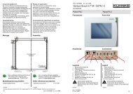
Ventura Scout 10,4" C - Kuhnke
Ventura Scout 10,4" C - Kuhnke
Ventura Scout 10,4" C - Kuhnke

Create successful ePaper yourself
Turn your PDF publications into a flip-book with our unique Google optimized e-Paper software.
Anwendungsbereich<br />
Der <strong>Ventura</strong> <strong>Scout</strong> ist als Betriebsmittel zum<br />
Einsatz in industrieller Umgebung konzipiert.<br />
Andere Anwendungen erfordern Rücksprache mit<br />
dem Werk. Bei nicht bestimmungsgemäßem<br />
Einsatz und eventuell hieraus resultierenden<br />
Schäden haftet der Hersteller nicht. Das Risiko<br />
trägt allein der Anwender.<br />
Zur bestimmungsgemäßen Verwendung gehört<br />
auch das Beachten der Betriebsanleitung.<br />
Inbetriebnahme<br />
Beim Betrieb elektrischer Geräte stehen<br />
zwangsläufig bestimmte Teile unter gefährlicher<br />
Spannung. Arbeiten an elektrischen Anlagen oder<br />
Betriebsmitteln dürfen nur von einer<br />
Elektrofachkraft oder von unterwiesenen<br />
Personen unter Anleitung und Aufsicht einer<br />
Elektrofachkraft den elektrotechnischen Regeln<br />
entsprechend vorgenommen werden.<br />
Montage<br />
4<br />
0<br />
-66<br />
-232<br />
-236<br />
0<br />
Eine vollständige Einbauzeichnung als<br />
PDF finden Sie im Internet unter<br />
www.kuhnke.com. "DOWNLOAD".<br />
Bestellbezeichnung Zubehör<br />
Bedienungsanleitung E 727 D<br />
30<br />
deutsch english<br />
Range of application<br />
The <strong>Ventura</strong> <strong>Scout</strong> is designed for use as<br />
equipment in industrial areas.<br />
For other applications, please consult us. <strong>Kuhnke</strong><br />
is not liable for any possible damages resulting<br />
from use in other than the designated<br />
applications. Such risk lies entirely with the user.<br />
Observance of the operation instructions is<br />
considered as part of the units’ designated use.<br />
Commissioning (electrical connection)<br />
During electrical operation certain parts inevitably<br />
carry lethal voltages. Work on the electrical<br />
system or equipment must only be carried out by<br />
a skilled electrician himself or by specially<br />
instructed personnel under the control and<br />
supervision of such an electrician and in<br />
accordance with the applicable electrical<br />
engineering rules.<br />
Assembly<br />
For a complete pdf-type installation<br />
drawing, browse for the "DOWNLOAD"<br />
section at www.kuhnke.com.<br />
Order references accessories<br />
Operating instructions E 727 GB<br />
<strong>Kuhnke</strong> Automation GmbH & Co. KG, Lütjenburger Str. <strong>10</strong>1, D-237<strong>10</strong> Malente, Internet: www.kuhnke.com<br />
Mittelachse Ausschnitt<br />
centerline of front panel cut out<br />
4/4 Doku <strong>10</strong>113862 / 04. November 2008<br />
170<br />
Fronttafel-Ausschnitt<br />
front panel cut out<br />
330 x 232<br />
270<br />
Bohrungen / drills<br />
Ø 5 mm (6x)<br />
Alle Maße in [mm] / All dimensions in [mm] Frontrahmen / front frame<br />
Frontansicht<br />
360 x 260<br />
Front view<br />
Mittelachse Frontplatte<br />
centerline of front panel<br />
3<strong>10</strong><br />
330<br />
340<br />
Doku <strong>10</strong>113862 04. November 2008<br />
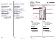
<strong>Ventura</strong> <strong>Scout</strong> <strong>10</strong>,4" C<br />
677.650.<strong>10</strong><br />
Panel PLC Panel PLC<br />
Frontansicht<br />
Anschlüsse<br />
Legende<br />
1 Betriebswahlschalter S1<br />
2 Statusanzeigen<br />
3 <strong>10</strong>/<strong>10</strong>0 Base-T Netzwerk-Anschluss<br />
(Ethernet), X2<br />
4 USB-Schnittstelle, X3 + Frontstecker<br />
5 Serielle Schnittstelle RS 232, X4, X5<br />
6 CANopen, X6, X7<br />
7 Serielle Schnittstelle RS 485, X8<br />
8 Stromversorgung X9<br />
Elektrostatisch gefährdete<br />
Bauelemente: Anschlusskontake der<br />
Steckverbinder nicht mit den Fingern<br />
berühren.<br />
Front view<br />
deutsch english<br />
Connections<br />
1 2 3 4 5 6 7 8<br />
Legend<br />
1 Mode switch, S1<br />
2 Status indications<br />
3 <strong>10</strong>/<strong>10</strong>0 Base-T network connection<br />
(Ethernet), X2<br />
4 USB Interface, X3 + front-facing connector<br />
5 Serial Interface RS 232, X4, X5<br />
8 CANopen, X6, X7<br />
9 Serial Interface, RS 485 X8<br />
<strong>10</strong> Power supply, X9<br />
Electrostatically endangered<br />
components: Do not touch the<br />
connection contacts of the plug/socket<br />
connectors.<br />
Doku <strong>10</strong>113862<br />
04. November 2008 1/4<br />
4
Funktion<br />
Die neu entwickelte Panel PLC <strong>Ventura</strong> <strong>Scout</strong> ist<br />
ein leistungsfähiges Steuerungssystem mit<br />
integriertem Bedien- und Anzeige-Bildschirm für<br />
den Einbau in Schaltpulten und Bedienkonsolen.<br />
Systemdaten<br />
Bauart: Gerät für Fronttafeleinbau<br />
Versorgungsspannung: 24 V DC -15% +20%<br />
Schutzart: IP 20, Front IP 65<br />
Zulässige Umgebungsbedingungen<br />
Lagertemperatur: -25...+70 °C<br />
Betriebs-Umgebungstemperatur: 0...50 °C<br />
Relative Luftfeuchte: 5...95 % (bei 25° C)<br />
Gewicht: ca. 5 kg<br />
Abmessungen:<br />
Breite: 360 mm<br />
Höhe: 260 mm<br />
Tiefe: 83 mm, (Frontplatte 6 mm)<br />
Einbautiefe: 77mm<br />
Betriebswahlschalter "S1"<br />
Betriebsartenumschaltung und Neustart.<br />
Schalter-<br />
Stellung<br />
CoDeSys<br />
RUN Programm im Zustand RUN,<br />
per Programmiergerät änderbar.<br />
STOP Programm im Zustand STOP.<br />
RESET Programmneustart mit gelöschten<br />
und RETAIN Variablen.<br />
Anzeigen<br />
LED 1<br />
(grün)<br />
an<br />
Status<br />
LED 3<br />
(grün)<br />
Zustand, Beschreibung<br />
EIN = korrekte Versorgungsspannung<br />
der Modulelektronik<br />
LED 4<br />
(rot)<br />
LED 5<br />
(rot)<br />
Beschreibung<br />
Zustand<br />
CoDeSys<br />
an aus - Programm: RUN<br />
aus an - Programm: STOP<br />
aus blinkt -<br />
Programm:<br />
FEHLERSTOP<br />
blinkt an -<br />
Programm:<br />
Breakpoint STOP<br />
- - an Modus: FORCE<br />
Function<br />
The newly developed Panel PLC <strong>Ventura</strong> <strong>Scout</strong> is<br />
a high-performance, compact control system with<br />
integrated operating and display screen for<br />
installation in control panels and operating<br />
consoles.<br />
System data<br />
Design: Unit to assembly in operating panel<br />
Supply voltage: 24 V DC -15% +20%<br />
Protection: IP 20, Front IP65<br />
Permitted ambient conditions<br />
Store temperature: -25...+70 °C<br />
Operating environmental temperature: 0...50 °C<br />
Humidity: 5...95 % (at 25° C)<br />
Weight: ca. 5 kg<br />
Measurements:<br />
Width: 360 mm<br />
High: 260 mm<br />
Depth: 83 mm, (Front 6 mm)<br />
Installation depth: 77mm<br />
Mode switch "S1"<br />
Mode switchover and restart.<br />
Switch<br />
position<br />
CoDeSys<br />
RUN Program states RUN, alterable by<br />
programming device.<br />
STOP Program states STOP.<br />
RESET Program restart with deleted<br />
RETAIN Variables.<br />
Indications<br />
LED 1<br />
(grün)<br />
on<br />
Status<br />
LED 3<br />
(grün)<br />
deutsch english<br />
State, description<br />
EIN = correct power supply of the<br />
module electronics<br />
LED 4<br />
(rot)<br />
LED 5<br />
(rot)<br />
State,<br />
description<br />
CoDeSys<br />
on off - Programm: RUN<br />
off on - Programm: STOP<br />
off flash -<br />
Programm:<br />
ERROR STOP<br />
flash on -<br />
Programm:<br />
Breakpoint STOP<br />
- - on Modus: FORCE<br />
2/4 Doku <strong>10</strong>113862 / 04. November 2008<br />
Ethernet Netzwerkanschluss"X2"<br />
Übertragungsgeschwindigkeit: <strong>10</strong>/<strong>10</strong>0 Base T<br />
Anschluss RJ 45 (Buchse):<br />
USB-Schnittstelle "X3"<br />
Frontstecker<br />
Spezifikation USB 1.1 (Master)<br />
high speed/ high current<br />
Stromversorgung max. 500 mA<br />
Anschluss Stecker Typ A<br />
Serielle Schnittstelle, RS 232"X4", "X5"<br />
Anschluss 9-polig, D_SUB Buchse<br />
Pin Funktion<br />
2 RxD<br />
3 TxD<br />
5 GND<br />
Feldbusschnittstelle "X6", "X7",<br />
CANopen<br />
Protokoll DSP 301<br />
Adresse 0-125 (per Software)<br />
Übertragungsgeschwindigkeit 50 - <strong>10</strong>00 kbit/s<br />
Anschluss 9-polig, D_SUB Stecker<br />
Pin Funktion<br />
2 CAN-L<br />
3 CAN-GND<br />
7 CAN-H<br />
Gehäuse Shield<br />
Serielle Schnittstelle ,RS 485, "X8"<br />
Anschluss 9-polig, D_SUB Buchse<br />
Pin Funktion<br />
1 RTxD-<br />
4 RTxD+<br />
5 GND<br />
Stromversorgung "X9"<br />
Anschluss 2-polig, Stecker, 2,5mm 2<br />
Pin Funktion<br />
L+ Versorgungsspannung +24 V DC<br />
M1 GND<br />
Eine zu hohe Spannung bzw. eine falsche<br />
Polarität an den Anschlüssen kann zur<br />
Zerstörung des IPC-Systems führen.<br />
Funktionserde<br />
Eine niederohmige Erdungsverbindung<br />
verbessert die Ableitung von Störungen, die über<br />
externe Stromversorgungskabel, Signalkabel<br />
oder Kabel zu Peripheriegeräten übertragen<br />
werden.<br />
Anschluss Flachstecker 6,3mm x 0,8mm<br />
deutsch english<br />
Ethernet network connection"X2"<br />
Transmission rate: <strong>10</strong>/<strong>10</strong>0 Base T<br />
Connection RJ 45 (Socket):<br />
USB Interface "X3"<br />
front-facing connector<br />
Specification USB 1.1 (master)<br />
high speed/ high current<br />
Power supply max. 500 mA<br />
Connection Plug Type A<br />
Serial Interface, RS 232"X4", "X5"<br />
Connection 9-pole, D_SUB socket<br />
Pin Function<br />
2 TxD<br />
3 RxD<br />
5 GND<br />
Field bus interface "X6", "X7",<br />
CANopen<br />
Protocol DSP 301<br />
Address 0-125 (by software)<br />
Transmission rate 50 - <strong>10</strong>00 kbit/s<br />
Connection 9-pole, D_SUB plug<br />
Pin Function<br />
2 CAN-L<br />
3 CAN-GND<br />
7 CAN-H<br />
cover Shield<br />
Serial Interface RS 485, "X8"<br />
Connection 9-pole, D_SUB socket<br />
Pin Function<br />
1 RTxD-<br />
4 RTxD+<br />
5 GND<br />
Power supply "X9"<br />
Connection 2-pole, Plug, 2,5mm 2<br />
Pin Function<br />
L+ Power supply +24 V DC<br />
M1 GND<br />
Excessive voltage or a wrong polarity at the<br />
connections can lead to the destruction of<br />
the IPC system<br />
Function Ground<br />
A low-impedance ground connection will improve<br />
the derivation of disturbances which are<br />
transferred over external power supply cables,<br />
signal cable or cable to peripherals.<br />
Connection Fast on 6.3 mm x 0.8 mm<br />
Doku <strong>10</strong>113862 / 04. November 2008 3/4