Profi I/O 690E+ Instruction Manual pdf - Kuhnke
Profi I/O 690E+ Instruction Manual pdf - Kuhnke
Profi I/O 690E+ Instruction Manual pdf - Kuhnke

You also want an ePaper? Increase the reach of your titles
YUMPU automatically turns print PDFs into web optimized ePapers that Google loves.
<strong>Kuhnke</strong> Electronics<br />
<strong>Instruction</strong> <strong>Manual</strong><br />
<strong>Profi</strong> I/O <strong>690E+</strong><br />
Remote I/O for PROFIBUS-DP<br />
E 408 GB 12.07.2002 / 67.115
This instruction manual is primarily intended for use by design, project, and<br />
development engineers. It does not contain any availability information.<br />
Data is only given to describe the product and must not be regarded as<br />
guaranteed properties in the legal sense. Any claims for damages - on<br />
whatever legal grounds - are excluded except for instances of deliberate<br />
intent or gross negligence on our part.<br />
We reserve the rights for errors, omissions and modifications.<br />
Reproduction even of extracts only with the editor's express and written<br />
prior consent.<br />
2 E 408 GB<br />
12.07.2002
Table of Contents<br />
Table of Contents<br />
1 Introduction ..............................................................................................11<br />
1.1 Moving on from separate controllers to networks ........................12<br />
1.2 <strong>Profi</strong> I/O <strong>690E+</strong> and PROFIBUS ..................................................14<br />
2 Reliability, Safety .....................................................................................15<br />
2.1 Application....................................................................................15<br />
2.2 Target Group ................................................................................15<br />
2.3 Reliability ......................................................................................15<br />
2.4 Notes ............................................................................................16<br />
2.4.1 Danger........................................................................................16<br />
2.4.2 Attention .....................................................................................16<br />
2.4.3 Note ............................................................................................16<br />
2.4.4 Under Construction.....................................................................17<br />
2.4.5 <strong>Instruction</strong> ...................................................................................17<br />
2.5 Safety ...........................................................................................18<br />
2.5.1 Project Planning and Installation ................................................19<br />
2.5.2 Maintenance and Servicing ........................................................20<br />
2.6 Electromagnetic Compatibility......................................................21<br />
2.6.1 Definition.....................................................................................21<br />
2.6.2 Interference Emission.................................................................22<br />
2.6.3 General Notes on Installation .....................................................22<br />
2.6.4 Protection against External Electrical Influences .......................23<br />
2.6.5 Cable Routing and Wiring ..........................................................23<br />
2.6.6 Location of Installation................................................................23<br />
2.6.7 Particular Sources of Interference..............................................24<br />
3 System Description..................................................................................25<br />
3.1 Mechanical Design .......................................................................26<br />
3.1.1 Earthing ......................................................................................26<br />
3.1.2 Installation ..................................................................................27<br />
3.2 Bus Interface Unit.........................................................................28<br />
3.2.1 System power supply .................................................................29<br />
3.2.2 System status indicators (LEDs) ................................................29<br />
3.2.3 Bus Connection ..........................................................................30<br />
E 408 GB 3<br />
12.07.2002
Table of Contents<br />
3.2.4 Setting the Station Address (Coding Switch) .............................31<br />
3.2.5 Technical data (basic bus interface unit data)............................32<br />
3.3 Extension......................................................................................33<br />
3.3.1 Connecting I/O Extensions.........................................................34<br />
3.3.2 Internal Module Bus....................................................................34<br />
3.3.3 Technical Data (Basic I/O Extension Data)................................35<br />
3.4 Inputs and Outputs .......................................................................36<br />
3.4.1 Line Interfacing ...........................................................................36<br />
3.4.2 I/O Supply...................................................................................40<br />
4 I/O Modules..............................................................................................43<br />
4.1 8 DI / 8 DO ...................................................................................43<br />
4.1.1 Connectors .................................................................................43<br />
4.1.2 Inputs..........................................................................................44<br />
4.1.3 Separation of potentials..............................................................44<br />
4.1.4 Outputs .......................................................................................44<br />
4.1.5 Light Emitting Diodes (LEDs) .....................................................45<br />
4.1.6 Technical Data............................................................................45<br />
4.1.7 PROFIBUS Data.........................................................................47<br />
4.2 8 DI / 8 Power DO ........................................................................49<br />
4.2.1 Connectors .................................................................................49<br />
4.2.2 Potential separation....................................................................50<br />
4.2.3 Inputs..........................................................................................50<br />
4.2.4 Outputs .......................................................................................50<br />
4.2.5 Light Emitting Diodes..................................................................50<br />
4.2.6 Technical Data............................................................................51<br />
4.2.7 PROFIBUS Data.........................................................................53<br />
4.3 16 DI / 16 DO ...............................................................................55<br />
4.3.1 Connectors .................................................................................55<br />
4.3.2 Potential separation....................................................................56<br />
4.3.3 Inputs..........................................................................................56<br />
4.3.4 Outputs .......................................................................................56<br />
4.3.5 Light Emitting Diodes..................................................................57<br />
4.3.6 Technical data ............................................................................57<br />
4 E 408 GB<br />
12.07.2002
Table of Contents<br />
4.3.7 PROFIBUS Data.........................................................................59<br />
4.4 16 DI.............................................................................................62<br />
4.4.1 Connectors .................................................................................62<br />
4.4.2 Inputs..........................................................................................63<br />
4.4.3 Light Emitting Diodes..................................................................63<br />
4.4.4 Technical Data............................................................................64<br />
4.4.5 PROFIBUS-Data ........................................................................65<br />
4.5 32 DI.............................................................................................67<br />
4.5.1 Connectors .................................................................................67<br />
4.5.2 Inputs..........................................................................................68<br />
4.5.3 Light Emitting Diodes..................................................................68<br />
4.5.4 Technical Data............................................................................69<br />
4.5.5 PROFIBUS-Data ........................................................................70<br />
4.6 16 DO ...........................................................................................73<br />
4.6.1 Connectors .................................................................................73<br />
4.6.2 Outputs .......................................................................................74<br />
4.6.3 Light Emitting Diodes..................................................................74<br />
4.6.4 Technical Data............................................................................75<br />
4.6.5 PROFIBUS-Data ........................................................................76<br />
4.7 32 DO ...........................................................................................78<br />
4.7.1 Connectors .................................................................................78<br />
4.7.2 Outputs .......................................................................................79<br />
4.7.3 Light Emitting Diodes..................................................................79<br />
4.7.4 Technical Data............................................................................80<br />
4.7.5 PROFIBUS-Data ........................................................................81<br />
4.8 8 DO, Relays ................................................................................84<br />
4.8.1 Connectors .................................................................................84<br />
4.8.2 Protective Action.........................................................................85<br />
4.8.3 Inputs..........................................................................................86<br />
4.8.4 Outputs .......................................................................................86<br />
4.8.5 Function......................................................................................87<br />
4.8.6 Light Emitting Diodes..................................................................88<br />
4.8.7 Technical Data............................................................................88<br />
E 408 GB 5<br />
12.07.2002
Table of Contents<br />
4.8.8 PROFIBUS Data.........................................................................89<br />
4.9 16 DI / 16 DO special-function .....................................................91<br />
4.9.1 Connectors .................................................................................92<br />
4.9.2 Potential separation....................................................................93<br />
4.9.3 Inputs..........................................................................................93<br />
4.9.4 Outputs .......................................................................................93<br />
4.9.5 Light Emitting Diodes..................................................................94<br />
4.9.6 Technical Data............................................................................94<br />
4.9.7 PROFIBUS Data.........................................................................96<br />
4.9.8 Standard Functions 16 DI / 16 DO .............................................98<br />
4.9.9 Special Function 16 DI/16 DO/2 32-bit Counters .....................100<br />
4.10 1 Counter (A, B, ref) / 13 DI / 16 DO ..........................................107<br />
4.10.1 Connectors .............................................................................107<br />
4.10.2 Potential separation................................................................108<br />
4.10.3 Inputs......................................................................................108<br />
4.10.4 Outputs ...................................................................................108<br />
4.10.5 Light Emitting Diodes..............................................................108<br />
4.10.6 Counter...................................................................................109<br />
4.10.7 Technical Data........................................................................110<br />
4.10.8 PROFIBUS Data.....................................................................112<br />
4.10.9 Example Counter Program.....................................................116<br />
4.11 2-Channel counter module.........................................................117<br />
4.11.1 Serial download interface .......................................................118<br />
4.11.2 Mode selector switch..............................................................118<br />
4.11.3 Power supply ..........................................................................119<br />
4.11.4 No separation of I/O potential.................................................119<br />
4.11.5 Inputs......................................................................................120<br />
4.11.6 Outputs ...................................................................................122<br />
4.11.7 Light emitting diodes...............................................................123<br />
4.11.8 Technical data ........................................................................124<br />
4.11.9 PROFIBUS Data.....................................................................126<br />
4.11.10 Usage notes .........................................................................146<br />
4.12 6 DI / 2 AO..................................................................................153<br />
6 E 408 GB<br />
12.07.2002
Table of Contents<br />
4.12.1 Connectors .............................................................................153<br />
4.12.2 Digital Inputs...........................................................................154<br />
4.12.3 Analogue Outputs...................................................................154<br />
4.12.4 Light Emitting Diodes..............................................................155<br />
4.12.5 Technical Data........................................................................156<br />
4.12.6 PROFIBUS Data.....................................................................158<br />
4.13 4 AI .............................................................................................162<br />
4.13.1 Connectors .............................................................................162<br />
4.13.2 Analogue Inputs......................................................................163<br />
4.13.3 Light Emitting Diodes..............................................................164<br />
4.13.4 Technical Data........................................................................165<br />
4.13.5 PROFIBUS Data.....................................................................167<br />
4.13.6 Software Filters.......................................................................172<br />
4.14 8 AI Thermo................................................................................174<br />
4.14.1 Connectors .............................................................................174<br />
4.14.2 Analogue Inputs......................................................................175<br />
4.14.3 Light Emitting Diodes..............................................................176<br />
4.14.4 Technical Data........................................................................177<br />
4.14.5 PROFIBUS Data.....................................................................179<br />
4.14.6 Temperatures .........................................................................183<br />
4.14.7 Sensor Connection.................................................................184<br />
4.15 4 AI Thermo................................................................................186<br />
4.15.1 Connectors .............................................................................186<br />
4.15.2 Analogue Inputs......................................................................187<br />
4.15.3 Light Emitting Diodes..............................................................188<br />
4.15.4 Technical Data........................................................................189<br />
4.15.5 PROFIBUS Data.....................................................................191<br />
4.15.6 Temperatures .........................................................................195<br />
4.15.7 Sensor Connection.................................................................196<br />
5 Software.................................................................................................198<br />
5.1 General.......................................................................................198<br />
5.1.1 <strong>Profi</strong> I/O <strong>690E+</strong> and PROFIBUS-DP ........................................199<br />
5.1.2 Example....................................................................................200<br />
E 408 GB 7<br />
12.07.2002
Table of Contents<br />
5.2 Master-Slave Communication ....................................................201<br />
5.2.1 Device Master File KUHN6900.GSD........................................201<br />
5.2.2 Initialising..................................................................................202<br />
5.2.3 Sending Parameter Data (Prm_Data) ......................................203<br />
5.2.4 General Bus Parameters..........................................................203<br />
5.2.5 Diagnostic Data (Diag_Data)....................................................206<br />
5.2.6 Data Exchange Between Master and Slave.............................212<br />
5.3 <strong>Kuhnke</strong> Controller Is Master.......................................................217<br />
5.3.1 Adding <strong>Profi</strong> I/O <strong>690E+</strong> to a Network .......................................217<br />
5.3.2 User Program for <strong>Kuhnke</strong> Masters...........................................238<br />
5.4 S7 (Siemens) Is Master..............................................................244<br />
5.4.1 Preparation ...............................................................................244<br />
5.4.2 Project Planning Using SIMATIC Manager ..............................246<br />
5.4.3 Configuring the Master .............................................................247<br />
5.4.4 Adding <strong>690E+</strong> to the Network...................................................249<br />
5.4.5 Parameters of <strong>Profi</strong> I/O <strong>690E+</strong> .................................................251<br />
5.4.6 Addressing................................................................................256<br />
5.4.7 Program Example.....................................................................256<br />
5.5 S5 (Siemens) Is Master..............................................................258<br />
5.5.1 Preparation ...............................................................................258<br />
5.5.2 Project Planning .......................................................................259<br />
5.5.3 Adding <strong>Profi</strong> I/O <strong>690E+</strong> to the Network ....................................260<br />
5.5.4 Configuring <strong>Profi</strong> I/O <strong>690E+</strong> .....................................................262<br />
5.5.5 Parameters of <strong>Profi</strong> I/O <strong>690E+</strong> .................................................265<br />
5.5.6 Further Settings ........................................................................265<br />
6 Appendix................................................................................................266<br />
6.1 Technical data ............................................................................266<br />
6.2 Part numbers..............................................................................268<br />
6.2.1 8 DI / 8 DO................................................................................268<br />
6.2.2 8 DI / 8 Power DO ....................................................................268<br />
6.2.3 16 DI / 16 DO............................................................................269<br />
6.2.4 16 DI .........................................................................................270<br />
6.2.5 32 DI .........................................................................................270<br />
8 E 408 GB<br />
12.07.2002
Table of Contents<br />
6.2.6 16 DO .......................................................................................271<br />
6.2.7 32 DO .......................................................................................271<br />
6.2.8 8 DO, Relays ............................................................................271<br />
6.2.9 16 DI / 16 DO Special-Function................................................272<br />
6.2.10 1 Counter (A, B, ref) / 13 DI / 16 DO ......................................272<br />
6.2.11 2-Channel counter module .....................................................272<br />
6.2.12 6 DI / 2 AO..............................................................................273<br />
6.2.13 4 AI .........................................................................................273<br />
6.2.14 8 AI Thermo............................................................................273<br />
6.2.15 4 AI Thermo............................................................................274<br />
6.2.16 PROFIBUS Accessories.........................................................275<br />
6.3 Versions .....................................................................................275<br />
6.4 Literature ....................................................................................276<br />
6.4.1 <strong>Kuhnke</strong> <strong>Manual</strong>s.......................................................................276<br />
6.4.2 Further PROFIBUS Reading ....................................................276<br />
6.5 Error Handling ............................................................................277<br />
6.5.1 Short-circuited Output (Message No. 1)...................................280<br />
6.5.2 Low Voltage (Message No. 2) ..................................................281<br />
6.5.3 Supply Voltage Back to Normal (Message 13) ........................282<br />
6.5.4 Communication Error (Message No. 4)....................................283<br />
6.5.5 Bus Error (Message No. 5).......................................................284<br />
6.5.6 Wrong Module Configuration (Message No. 7)........................284<br />
6.5.7 Parameter Error (Message No. 8) ............................................285<br />
6.6 Sales & Service ..........................................................................286<br />
6.6.1 Worldwide.................................................................................286<br />
6.6.2 Germany...................................................................................289<br />
6.7 Index...........................................................................................292<br />
E 408 GB 9<br />
12.07.2002
Table of Contents<br />
10 E 408 GB<br />
12.07.2002
1 Introduc tion<br />
Introduction<br />
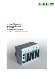
<strong>Profi</strong> I/O <strong>690E+</strong> is a modular input/output device. It integrates<br />
in PROFIBUS-DP network configurations for the<br />
remote reading of inputs and actuating of outputs.<br />
Devices can be delivered with terminals for two-core or<br />
three-core connectors so that relay coils, proximity<br />
switches etc. can be supplied via the same cable as the<br />
signal line – without any need for extra terminal blocks.<br />
Due to its room-saving design, the device can be installed<br />
exactly where input signals are generated or output signals<br />
are needed.<br />
The housing contains a device for snapping the whole unit<br />
on to a carrier rail.<br />
Bus interface unit Extension Extension Extension<br />
Fig.: <strong>Profi</strong> I/O <strong>690E+</strong>, bus interface unit with I/Os and<br />
3 I/O extensions<br />
E 408 GB 11<br />
12.07.2002
Introduction<br />
1.1 Moving on from separate controllers to<br />
networks<br />
For three main reasons, programmable logic controllers<br />
(PLCs) play an important role in industrial automation:<br />
� they are universally applicable,<br />
� programming is easy and comprehensible,<br />
� there are extensive tools for testing and start-up.<br />
As problem-oriented microcomputers with an everincreasing<br />
capacity and functionality, PLCs have taken on<br />
more and more features of process computing. They have<br />
become universal instruments of automation which have<br />
found acceptance in a wide range of action.<br />
A strong tendency towards hierarchically organised process<br />
control systems has developed since which are characterised<br />
by tasks being divided up among and completed<br />
by the part systems that are optimally suited for the job.<br />
In these hierarchical architectures, PLCs usually perform<br />
at the process interface level whereas PCs are used for<br />
calculating and managing the large volumes of data to be<br />
dealt with at the control level.<br />
12 E 408 GB<br />
12.07.2002
Introduction<br />
Task separation equals decentralisation<br />
Adding further components such as sensors and actuators<br />
produces field-level networks.<br />
Successful communication between PLCs, PLCs and<br />
other control units or devices, or between PLCs and PCs<br />
largely depends on high-performance interfaces and<br />
transfer lines.<br />
Decentralisation benefits<br />
� Fewer multi-core cables;<br />
� Material (cables, terminals, connectors...);<br />
� Space (conduits, junction boxes, switching cabinet);<br />
� Installation (time, fewer possibilities for mistakes);<br />
� Increased functionality;<br />
� Program structure similar to object structure, i.e. improved<br />
comprehensibility;<br />
� Improved fault tolerance (if one part of the system<br />
fails, other parts can continue to work);<br />
� Reduced commissioning and start-up times;<br />
� “Laboratory” tests of individual stations;<br />
� Vendor-independence.<br />
However, a standardised solution for all part-systems is<br />
required for all of these benefits to take effect. What you<br />
need is an acceptable compromise for the vast majority of<br />
applications.<br />
Speed, the reliability of data transfer, and an open-system<br />
design are the key factors. The standardised system to<br />
meet all of these requirements goes by the name of<br />
PROFIBUS.<br />
E 408 GB 13<br />
12.07.2002
Introduction<br />
1.2 <strong>Profi</strong> I/O <strong>690E+</strong> and PROFIBUS<br />
<strong>Profi</strong> I/O <strong>690E+</strong> is equipped with a PROFIBUS port. As a<br />
so-called slave device it can provide services for intelligent<br />
bus stations (masters). These include:<br />
� picking up signals from switches, sensors, proximity<br />
switches etc. and forwarding them to the master;<br />
� gating commands of the higher-level controller to the<br />
outputs as signals for switching on and off relays,<br />
valves etc.<br />
<strong>Profi</strong> I/O <strong>690E+</strong> uses the PROFIBUS-DP protocol for<br />
communication with the master. This bus protocol is standardised<br />
in European Standard EN 50 170, Vol. 2.<br />
Extensions to the controller’s I/O range<br />
PROFIBUS can also be seen as an easy means of increasing<br />
the number of inputs and outputs of a controller.<br />
For example, you can install one or several <strong>Profi</strong> I/O<br />
<strong>690E+</strong> devices in one single switching cabinet. In this<br />
case, PROFIBUS is not used as a field bus in the true<br />
sense of the word, but as a means of connecting additional<br />
peripherals.<br />
14 E 408 GB<br />
12.07.2002
2 Reliabili ty, Safety<br />
2.1 Application<br />
2.2 Target Group<br />
2.3 Reliability<br />
Reliability & Safety<br />
<strong>Kuhnke</strong> products are designed as resources for use in industrial<br />
environments.<br />
All other applications need to be discussed with the factory<br />
first. The manufacturer shall neither be liable for any<br />
other than the intended use of our products nor for any<br />
ensuing damages. The risk shall be borne by the operator<br />
alone. The use as intended includes that you read and<br />
apply all information and instructions contained in this<br />
manual.<br />
This instruction manual contains all information necessary<br />
for the use of the described product (control device, control<br />
terminal, software, etc.) according to instructions. It is<br />
written for the personnel of the construction, project planning,<br />
service and commissioning departments. For proper<br />
understanding and error-free application of technical descriptions,<br />
instructions for use and particularly of notes of<br />
danger and warning, extensive knowledge of automation<br />
technology is compulsory.<br />
Reliability of <strong>Kuhnke</strong> controllers is brought to the highest<br />
possible standards by extensive and cost-effective means<br />
in their design and manufacture.<br />
These include:<br />
� selecting high-quality components,<br />
� quality agreements with our suppliers,<br />
� measures for the prevention of static charge during<br />
the handling of MOS circuits,<br />
� worst case planning and design of all circuits,<br />
E 408 GB 15<br />
12.07.2002
Reliability & Safety<br />
2.4 Notes<br />
2.4.1 Danger<br />
2.4.2 Attention<br />
2.4.3 Note<br />
� inspections at various stages of fabrication,<br />
� computer-aided tests of all assembly groups and their<br />
interaction in the circuit,<br />
� statistical assessment of the quality of fabrication and<br />
of all returned goods for the immediate taking of appropriate<br />
corrective actions.<br />
Despite the measures described in chapter 2.3 , the occurrence<br />
of faults or errors in electronic control units -<br />
even if most highly improbable - must be taken into consideration.<br />
Please pay particular attention to the additional notes<br />
which we have marked by symbols in this instruction<br />
manual. While some of these notes make you aware of<br />
possible dangers, others are intended as a means of orientation.<br />
They are described further down below in descending<br />
order of importance.<br />
This symbol warns you of dangers which may cause<br />
death or grievous bodily harm if operators fail to implement<br />
the precautions described.<br />
This symbol draws your attention to information you must<br />
take a look at to avoid malfunctions, possible material<br />
damage or even dangerous states.<br />
This symbol draws your attention to additional information<br />
concerning the use of the described product. It may<br />
also indicate a cross reference to information to be found<br />
elsewhere (e. g. in other manuals).<br />
16 E 408 GB<br />
12.07.2002
2.4.4 Under Con struction<br />
2.4.5 <strong>Instruction</strong><br />
Reliability & Safety<br />
This symbol tells you that the function described was not<br />
or not fully available at the time this document went to<br />
press.<br />
Wherever you see these symbols in the left margin, you<br />
will find a list of steps instructing you to take the appropriate<br />
computer or hardware actions.<br />
They are intended as a means of orientation at places<br />
where steps of procedures and background information<br />
alternate (e. g. in beginner's manuals).<br />
E 408 GB 17<br />
12.07.2002
Reliability & Safety<br />
2.5 Safety<br />
Our products normally become part of larger systems or<br />
installations. The information below is intended to help<br />
you integrate the product into its environment without<br />
dangers to humans or material/equipment.<br />
To achieve a high degree of conceptual safety in planning<br />
and installing an electronic controller it is essential<br />
to exactly follow the instructions given in the manual because<br />
wrong handling could lead to rendering measures<br />
against dangers ineffective or to creating additional dangers.<br />
18 E 408 GB<br />
12.07.2002
2.5.1 Project Pla nning and Installation<br />
Reliability & Safety<br />
� 24 V DC power supply: Generate as electrically<br />
safely separated low voltage. Suitable devices are,<br />
for example, split transformers constructed in compliance<br />
with European Standard EN 60742 (corresponds<br />
to VDE 0551).<br />
� In case of power breakdowns or power fades: the<br />
program structure is to ensure that a defined state at<br />
restart excludes all dangerous states.<br />
� Emergency switch-off installations must comply with<br />
EN 60204/IEC 204 (VDE 0113). They must be effective<br />
at any time.<br />
� Safety and precautions regulations for qualified applications<br />
have to be complied with.<br />
� Please pay particular attention to the notes of warning<br />
which, at relevant places, will make you aware of<br />
possible sources of dangerous mistakes or faults.<br />
� Relevant standards and VDE regulations are to be<br />
complied with in every case.<br />
� Control elements are to be installed in such a way as<br />
to exclude unintended operation.<br />
� Control cables are to be laid in such a way as to exclude<br />
interference (inductive or capacitive) which<br />
could influence controller operation or its functionality.<br />
E 408 GB 19<br />
12.07.2002
Reliability & Safety<br />
2.5.2 Maintenan ce and Servicing<br />
� Precautions regulation VBG 4.0 must be observed,<br />
and section 8 (Admissible deviations when working<br />
on parts) in particular, when measuring or checking a<br />
controller in a power-up condition .<br />
� Repairs must be carried out by specially trained <strong>Kuhnke</strong><br />
staff only (usually in the main factory in Malente).<br />
Warranty expires in every other case.<br />
� Only use parts approved of by <strong>Kuhnke</strong>. Only genuine<br />
<strong>Kuhnke</strong> modules must be used in modular controllers.<br />
� Modular systems: Always plug or unplug modules in<br />
a power-down state. You might otherwise damage<br />
the modules or (possibly not immediately recognisably!)<br />
inhibit their functionality.<br />
� Always dispose of any batteries and accumulators as<br />
hazardous waste.<br />
20 E 408 GB<br />
12.07.2002
2.6 Electromagnetic Compatibility<br />
2.6.1 Definition<br />
Reliability & Safety<br />
Electromagnetic compatibility is the ability of a device to<br />
function satisfactorily in its electromagnetic environment<br />
without itself causing any electromagnetic interference<br />
that would be intolerable to other devices in this environment.<br />
Of all known phenomena of electromagnetic noise, only a<br />
certain range occurs at the location of a given device. It is<br />
defined in the relevant product standards.<br />
The international standard regulating construction and<br />
degree of noise resistance of programmable logic controllers<br />
is IEC 61131-2 which, in Europe, has been the basis<br />
for European Standard EN 61131-2.<br />
Refer to IEC 61131-4, User's Guideline, for general installation<br />
instructions to be complied with to ensure that<br />
hardware interface factors and the ensuing noise voltages<br />
are limited to tolerable levels.<br />
E 408 GB 21<br />
12.07.2002
Reliability & Safety<br />
2.6.2 Interferenc e Emission<br />
Interfering emission of electromagnetic fields, HF<br />
in acc. with EN 55011, limiting value class A, Group 1<br />
If the controller is designed for use in residential areas,<br />
then high-frequency emissions must comply with limiting<br />
value class B as described in EN 55011.<br />
Fitting the controller into an earthed metal cabinet and<br />
equipping the supply cables with filters may be appropriate<br />
means of maintaining the relevant limiting values.<br />
2.6.3 General N otes on Installation<br />
As component parts of machines, facilities and systems,<br />
electronic control systems must comply with valid rules<br />
and regulations, depending on their field of application.<br />
General requirements concerning the electrical equipment<br />
of machines and aiming at the safety of these machines<br />
are contained in Part 1 of European Standard EN 60204<br />
(corresponds to VDE 0113).<br />
For safe installation of our control system please observe<br />
the following notes (� 2.6.4 and following).<br />
22 E 408 GB<br />
12.07.2002
Reliability & Safety<br />
2.6.4 Protection against External Electrical Influences<br />
Connect the control system to the protective earth conductor<br />
to eliminate electromagnetic interference. Ensure<br />
practical wiring and laying of cables.<br />
2.6.5 Cable Rou ting and Wiring<br />
Lay power supply circuits separately, never together with<br />
control current loops:<br />
� DC voltage 60 V... 400 V<br />
� AC voltages 25 V ... 400 V<br />
Joint laying of control current loops is allowed for:<br />
� shielded data signals<br />
� shielded analogue signals<br />
� unshielded digital I/O lines<br />
� unshielded DC voltages < 60 V<br />
� unshielded AC voltages < 25 V<br />
2.6.6 Location o f Installation<br />
2.6.6.1 Temperatur e<br />
2.6.6.2 Dirt<br />
Make sure that there are no impediments due to temperatures,<br />
dirt, impact, vibration and electromagnetic interference.<br />
Consider heat sources such as general heating of rooms,<br />
sunlight, heat accumulation in assembly rooms or control<br />
cabinets.<br />
Use suitable casings to avoid possible negative influences<br />
due to humidity, corrosive gas, liquid or conducting dust.<br />
E 408 GB 23<br />
12.07.2002
Reliability & Safety<br />
2.6.6.3 Impact and Vibration<br />
Consider possible influences caused by motors, compressors,<br />
transfer lines, presses, ramming machines and vehicles.<br />
2.6.6.4 Electromagn etic Interference<br />
Consider electromagnetic interference from various<br />
sources near the location of installation: motors, switching<br />
devices, switching thyristors, radio-controlled devices,<br />
welding equipment, arcing, switched-mode power supplies,<br />
converters / inverters.<br />
2.6.7 Particular Sources of Interference<br />
2.6.7.1 Inductive Ac tuators<br />
Switching off inductance (such as from relays, contactors,<br />
solenoids or switching magnets) produces overvoltages. It<br />
is necessary to reduce these extra voltages to a minimum.<br />
Reducing elements may be diodes, Z-diodes, varistors or<br />
RC elements. To find the best adapted elements, we recommend<br />
that you contact the manufacturer or supplier of<br />
the corresponding actuators for the relevant information.<br />
24 E 408 GB<br />
12.07.2002
3 System Description<br />
System Description<br />
<strong>Profi</strong> I/O <strong>690E+</strong> is a remote, modular input/output unit<br />
(I/O). Up to three I/O extensions can be connected.<br />
<strong>Profi</strong> I/O <strong>690E+</strong> supports the PROFIBUS-DP protocol for<br />
communication via PROFIBUS at transfer rates of up to<br />
12 Mbit/s. The device automatically adopts the transfer<br />
rate set by the master.<br />
There is a whole range of differently configured I/O modules<br />
available.<br />
The system is made up of various components that can<br />
be combined as the case requires.<br />
Bus interface<br />
it<br />
I/O extension<br />
E 408 GB 25<br />
12.07.2002
Mechanical Design, Installation<br />
3.1 Mechanical Design<br />
3.1.1 Earthing<br />
right side panel<br />
left side panel<br />
The housing mainly consists of an aluminium frame with a<br />
snap-on device for carrier rail installation. The side panels<br />
of galvanised sheet steel are riveted to the aluminium<br />
frame. The plastic lid is held by studs that snap into<br />
notches in the side panels.<br />
The lid can be removed easily to set the coding switch inside<br />
the bus interface unit, for example, or to attach the<br />
ribbon cable connector of an I/O extension.<br />
Make sure to properly earth the metal housing via the<br />
earthing pin provided in either of the two side panels.<br />
Earthing wire<br />
� Diameter: min. 2.5 sqmm<br />
� Length: as short as possible<br />
Connector<br />
� Flat cable plug 6.3 x 0.8 mm<br />
Function<br />
� Earthing of the device also earth-connects the functions.<br />
� Spring-actuated contacts on the PCB make a capacitive<br />
earthing contact between the +24V DC and 0V<br />
connectors and the housing, also serving as a bleed<br />
line to earth for line-conducted RFI noise.<br />
� The casing of the PROFIBUS plug is directly connected<br />
to the earth connection of functions. This is<br />
also where the cable shielding is attached<br />
This earthing is no safeguard against high contact voltage.<br />
Proper protection is only ensured by supplying the<br />
device with appropriately separated small voltages (�<br />
2.5.1).<br />
(Exception: � 4.8.2)<br />
26 E 408 GB<br />
12.07.2002
3.1.2 Installation<br />
System Description<br />
Bus interface units and I/O extensions install on carrier<br />
rails (in compliance with DIN EN 50022, 35 x 7.5 mm).<br />
Procedure<br />
1.<br />
Push the device up the<br />
carrier rail as illustrated,<br />
making sure to insert and<br />
load the metal spring between<br />
carrier rail and<br />
mounting surface.<br />
Metal spring<br />
2.<br />
Press the device against<br />
the mounting surface until<br />
it snaps in properly.<br />
E 408 GB 27<br />
12.07.2002
Bus Interface Unit<br />
3.2 Bus Interface Unit<br />
The bus interface unit is the basic device. It consists of a<br />
processor board provided with a bus connector, the system<br />
supply and the coding switch (under the lid).<br />
The basic device is delivered with one I/O module for optional<br />
input/output configuration (� 0).<br />
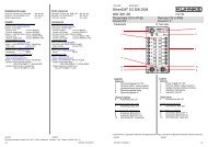
The illustration below shows a bus interface unit with 16<br />
digital inputs, 16 digital outputs and 1-wire spring terminals:<br />
System status indicators (LEDs)<br />
Coding switch (under the lid)<br />
run<br />
failure<br />
PROFIBUS-DP<br />
24VDC<br />
L1- L1+<br />
Bus connector<br />
System power supply<br />
I/O module (� 0)<br />
L2-L2+<br />
24VDC 0 1 2 3 4 5 6 7 .0 .1 .2 .3 .4 .5 .6 .7<br />
Digital Output 24V DC 0,5A<br />
Digital Input 24V DC<br />
0 1 2 3 4 5 6 7 .0 .1 .2 .3 .4 .5 .6 .7<br />
28 E 408 GB<br />
12.07.2002
3.2.1 System po wer supply<br />
System Description<br />
System power is supplied via a plug-type terminal block<br />
for two wires. System power supplies the bus interface<br />
unit, the internal module bus as well as the logic circuits of<br />
the I/O boards.<br />
Voltage: 24 V DC -20%/+25%<br />
Power consumption: max. approx. 200 mA in fully<br />
equipped configurations<br />
Connectors: L1- 0V<br />
L1+ +24V DC<br />
0V<br />
The actual inputs and outputs are supplied separately (�<br />
3.4.1).<br />
Power supply lines must not be connected through from<br />
one <strong>Profi</strong> I/O <strong>690E+</strong> supply terminal to the next. To exclude<br />
failures during operation, make sure to establish a<br />
star topology with a central supply connector and as<br />
short supply lines as possible.<br />
3.2.2 System status indicators (LEDs)<br />
+ 24V DC<br />
Two light emitting diodes indicate the device’s current<br />
state:<br />
LED Colour State Function<br />
run green on ready<br />
off not ready<br />
failure red flashing fault (� 0 )<br />
E 408 GB 29<br />
12.07.2002
Bus Interface Unit<br />
3.2.3 Bus Conn ection<br />
9 8 7 6<br />
5 4 3 2 1<br />
The PROFIBUS cable connects to the 9-pin D-Sub socket<br />
labelled "PROFIBUS-DP" on the lid of the housing.<br />
Pin wiring<br />
Pin Function<br />
1 unused<br />
2 unused<br />
3 RxD/TxD-P receive/transmit data, plus<br />
4 CNTR-P direction signal for repeater<br />
(+5V)<br />
5 DGnd data reference potential (0 V)<br />
6 VP supply voltage (+ 5 V)<br />
7 unused<br />
8 RxD/TxD-N receive/transmit data, minus<br />
9 unused<br />
Plug<br />
casing<br />
cable<br />
shielding<br />
Data transfer speed (baud rate)<br />
<strong>Profi</strong> I/O <strong>690E+</strong> supports the following baud rates:<br />
9.6 kbit/s, 19.2 kbit/s, 93.75 kbit/s, 187.5 kbit/s, 500 kbit/s,<br />
1500 kbit/s, 3000 kbit/s, 6000 kbit/s, and 12000 kbit/s. It<br />
automatically adopts the baud rate set by the master. You<br />
do not need to change any settings on the device.<br />
For information on bus cable installation and shielding,<br />
connectors, bus nodes and bus terminators please refer<br />
to Appendix "B. PROFIBUS installation".<br />
30 E 408 GB<br />
12.07.2002
System Description<br />
3.2.4 Setting the Station Address (Coding Switch)<br />
Every bus station has its own address to be used by other<br />
stations for communication.<br />
<strong>Profi</strong> I/O <strong>690E+</strong> features a coding switch for setting the<br />
address. The coding switch is located on the processor<br />
board under the lid of the bus interface unit's housing.<br />
Switch off all supply voltages (system and I/Os) before<br />
you remove the lid. Avoid electrostatic discharge to PCBs<br />
or any of the components placed on the PCBs. Noncompliance<br />
might damage the sensitive parts.<br />
The lid is snapped on to the device's side panels. Carefully<br />
push out one of the side panels to unlock the lid.<br />
Take the lid off. The coding switch is located in the top left<br />
corner of the bottom PCB (� illustration on the left).<br />
Coding switch<br />
1 2 3 4 5 6 7 8<br />
PROFIBUS<br />
station address<br />
off off off off off off off off 0<br />
on off off off off off off off 1<br />
off on off off off off off off 2<br />
on on off off off off off off 3<br />
etc. down to:<br />
off on on on on on on off 126<br />
on on on on on on on off<br />
x x x x x x x on<br />
Not allowed!<br />
1 2 4 8 16 32 64 none � Significance (binary)<br />
The address applies to the entire device including all I/O<br />
extensions.<br />
E 408 GB 31<br />
12.07.2002
Bus Interface Unit<br />
3.2.5 Technical data (basic bus interface unit data)<br />
Type ..................................................... open<br />
Installation............................................ on carrier rail<br />
Admissible ambient conditions<br />
Storage temperature....................... -25...+70 °C<br />
Ambient temp. during operation ..... 0...55 °C<br />
Relative humidity ............................ 5...95 %<br />
Dimensions L x W x H [mm]<br />
1-core connection ........................... 151.6 x 89.6 x 73<br />
3-core connection (single-ended) ... 151.6 x 119,6 x 73<br />
3-core connection (double-ended).. 151.6 x 149 x 73<br />
Weight [g]<br />
1-core connection ........................... 580<br />
3-core connection (single-ended) ... 670<br />
3-core connection (double-ended).. 760<br />
System power supply<br />
Voltage............................................ 24 V DC 20%/+25%<br />
Max. power consumption................ appr. 200 mA in fully conf. systems<br />
PROFIBUS<br />
Connector ....................................... 9-pin Sub-D socket<br />
Potential separation........................ yes<br />
Protocol........................................... PROFIBUS-DP<br />
Max. baud rate................................ 12 Mbit/s<br />
Local system status indicators............. LEDs 1<br />
LED “run“ ........................................ ready (operating)<br />
LED “failure“.................................... not ready (failure)<br />
Remote system messages ............. diagnostic data via PROFIBUS<br />
Extensions ........................................... up to 3 I/O extensions, seriesconnected<br />
via ribbon cable and<br />
plug<br />
Inputs and outputs ............................... � chapter 0<br />
1 Integral LEDs: light emitting diodes (class 1 in compl. with EN 60825-1)<br />
32 E 408 GB<br />
12.07.2002
3.3 Extension<br />
System Description<br />
I/O extensions are separate devices equipped with an I/O<br />
module. There are various I/O extensions available each<br />
with a different input/output configuration (� 0. I/O Modules).<br />
You can connect up to 3 I/O extensions to any one basic<br />
bus interface unit. Every extension module has a short flat<br />
ribbon cable and plug on its left side. The plug connects to<br />
its counterpart located under the lid of the preceding device.<br />
Conduct the ribbon cable through the opening in the<br />
device's side panel.<br />
Bus interface unit Extension Extension Extension<br />
E 408 GB 33<br />
12.07.2002
I / O Extensions<br />
3.3.1 Connectin g I/O Extensions<br />
Switch off all supply voltages (system and I/Os) before<br />
you remove the lid. Avoid electrostatic discharge to PCBs<br />
or any of the components placed on the PCBs. Noncompliance<br />
might damage the sensitive parts.<br />
The lid is snapped on to the device's side panels. Carefully<br />
push out one of the side panels to unlock the lid.<br />
Take the lid off. The ribbon cable connector is located on<br />
the right side of the I/O module. Connect the ribbon cable<br />
and close the lid when you’re done.<br />
Please only use the ribbon cable delivered with the device.<br />
Do not replace it by a longer cable because this<br />
may render the device susceptible to interference.<br />
3.3.2 Internal M odule Bus<br />
The separate units interconnect via the internal module<br />
bus which carries all serial communication data between<br />
the bus interface unit and the I/O modules.<br />
The module bus also supplies the I/O modules with the 5<br />
V system voltage (logic circuit supply).<br />
34 E 408 GB<br />
12.07.2002
System Description<br />
3.3.3 Technical Data (Basic I/O Extension Data)<br />
Type ..................................................... open<br />
Installation............................................ on carrier rail<br />
Admissible ambient conditions<br />
Storage temperature....................... -25...+70 °C<br />
Ambient temp. during operation ..... 0...55 °C<br />
Relative humidity ............................ 5...95 %<br />
Dimensions L x W x H [mm]<br />
1-core connector............................. 111.6 x 89.6 x 73<br />
3-core connector (single-ended)..... 111.6 x 119.6 x 73<br />
3-core connector (double-ended) ... 111.6 x 149 x 73<br />
Weight [g]<br />
1-core connector............................. 390<br />
3-core connector (single-ended)..... 470<br />
3-core connector (double-ended) ... 550<br />
System supply...................................... 5 V DC (from the bus interface<br />
unit)<br />
Connection to bus interface unit .......... up 3 I/O extensions in series via<br />
ribbon cable and plug<br />
Inputs and outputs ............................... � chapter 0. “I/O modules“<br />
E 408 GB 35<br />
12.07.2002
I / O Interfacing<br />
3.4 Inputs and Outputs<br />
3.4.1 Line Interf acing<br />
There is a large variety of differently configured I/O modules<br />
available. An I/O module can either be integrated in<br />
the bus interface unit or used as a separate extension<br />
module.<br />
Since 1999 all I/O modules have been equipped with<br />
plug-type connectors. There are two alternative plug<br />
types: screw terminals and spring terminals. The I/O<br />
modules with digital I/Os are also available with 3-core<br />
connectors.<br />
The line interfacing technique is indicated by the "B"<br />
specifier in the device's part number:<br />
Part number structure:<br />
Line interfacing:<br />
6 9 0 . x B x . x x . x x<br />
1-core screw terminals 2<br />
1-core spring terminals 1<br />
3-core screw terminals 5<br />
3-core spring terminals 4<br />
Maximum diameter of wire: 2.5 sqmm<br />
36 E 408 GB<br />
12.07.2002
3.4.1.1 1-Core Con nector<br />
Supply<br />
System Description<br />
Example of an 8I/8O extension with screw terminals<br />
Part number 690.522.11.00:<br />
89,6<br />
+ 24V DC<br />
0 V<br />
111,6<br />
24VDC<br />
L2+ L2-<br />
E 408 GB 37<br />
12.07.2002
I / O Interfacing<br />
3.4.1.2 3-Core Con nector, Single-Ended<br />
Supply<br />
Example of an 8I/8O extension with screw terminals<br />
Part number 690.552.11.00:<br />
89,6<br />
+ 24V DC<br />
0 V<br />
111,6<br />
24VDC<br />
L2+ L2-<br />
38 E 408 GB<br />
12.07.2002<br />
+ -<br />
119,6
3.4.1.3 3-Core Con nector, Double-Ended<br />
Supply<br />
System Description<br />
Example of an 16I/16O extension with screw terminals<br />
Part number 690.552.22.00:<br />
+ 24V DC<br />
0 V<br />
89,6<br />
+ -<br />
L2- L2+<br />
24VDC<br />
E 408 GB 39<br />
12.07.2002<br />
+ -<br />
149
I / O Supply, Potential separation<br />
3.4.2 I/O Supply<br />
The outputs of the I/O modules are supplied separately.<br />
The potential of this supply voltage is separated from the<br />
internal module bus and the internal logic circuit supply.<br />
Power supply lines must not be connected through from<br />
one <strong>Profi</strong> I/O <strong>690E+</strong> supply terminal to the next. To exclude<br />
failures during operation, make sure to establish a<br />
star topology with a central supply connector and as<br />
short supply lines as possible.<br />
For details please refer to chapters 3.4.1 (line interfacing)<br />
and 3.4.1(I/O modules).<br />
40 E 408 GB<br />
12.07.2002
3.4.2.1 Modules wit h I/O-potential separation<br />
Potential<br />
separation<br />
System Description<br />
In these modules inputs and outputs are supplied<br />
separately via the connectors L2+ and L2-. The potential<br />
of this supply is separated from the internal logic circuit<br />
supply, which is connected to the I/O modules via IMBus<br />
(Internal module bus) by optocouplers.<br />
Through this potential compensation currents are<br />
prevented between the I/O level and the logic.<br />
run<br />
failure<br />
PROFIBUS-DP<br />
24VDC<br />
L1- L1+<br />
L2-L2+<br />
24VDC 0 1 2 3 4 5 6 7 .0 .1 .2 .3 .4 .5 .6 .7<br />
Digital Output 24V DC 0,5A<br />
Digital Input 24V DC<br />
0 1 2 3 4 5 6 7 .0 .1 .2 .3 .4 .5 .6 .7<br />
This potential separation does not apply to input interconnections<br />
and connections to the outputs as these elements<br />
interconnect via connector "L2-".<br />
E 408 GB 41<br />
12.07.2002
I / O Supply, Potential separation<br />
3.4.2.2 Modules wit hout I/O-potential separation<br />
no<br />
potential<br />
separation<br />
3.4.2.2.1 Installation n otes<br />
In these modules inputs and outputs are also supplied via<br />
the connectors L2+ and L2-. But there is no potential<br />
separation to the internal logic circuit supply, which is<br />
connected to the I/O modules via IMBus (Internal module<br />
bus).<br />
Through this potential compensation currents are<br />
prevented between the I/O level and the logic.<br />
run<br />
failure<br />
PROFIBUS-DP<br />
24VDC<br />
L1- L1+<br />
L2-L2+<br />
24VDC 0 1 2 3 4 5 6 7 .0 .1 .2 .3 .4 .5 .6 .7<br />
Digital Output 24V DC 0,5A<br />
Digital Input 24V DC<br />
0 1 2 3 4 5 6 7 .0 .1 .2 .3 .4 .5 .6 .7<br />
Please, pay attention to the following installation notes<br />
when installing power supply, to prevent destructions in<br />
the modules.<br />
� Connect the 0V supply at L2- always at first, later on<br />
+ 24 V at L2+.<br />
� Secure, that the 0V supply never will be separated<br />
from L2- , bevore + 24 V is separated from L2+.<br />
You this way prevent high compensatory currents via the<br />
0V connection of the IMBus, which may destroy any<br />
components of the modules.<br />
42 E 408 GB<br />
12.07.2002
4 I/O Mod ules<br />
4.1 8 DI / 8 DO<br />
4.1.1 Connector s<br />
I/O Modules<br />
This chapter describes the different I/O modules that can<br />
be used either as integral parts of bus interfacing units or<br />
as extensions. The abbreviations stand for:<br />
DI: Digital Input DO: Digital Output<br />
AI: Analogue Input AO: Analogue Output<br />
This module has 8 digital inputs and 8 digital outputs. You<br />
can install it in the bus interface unit or add it as an extension.<br />
Digital Input 24V DC<br />
Digital Output 24V DC 0,5A<br />
0 1 2 3 4 5 6 7 .0.1.2.3.4.5.6.724VDC<br />
L2+L2-<br />
Supply to outputs (L2+, L2-) and inputs (L2-)<br />
� “L2+“ + 24V DC<br />
� “L2-“ 0V<br />
Digital inputs (DI) 24V DC<br />
� “0“...“7“ inputs 0...7<br />
Digital outputs (DO) 24V DC 0.5A<br />
� “.0“...“.7“ outputs 0...7<br />
E 408 GB 43<br />
12.07.2002<br />
8 DI / 8 DO<br />
8 DE / 8 Power DO<br />
16 DI /16 DO<br />
16 DE<br />
32 DE<br />
Register<br />
Register
8 DI / 8 DO<br />
4.1.2 Inputs<br />
The inputs are supplied with +24 V DC. Connect the 0V<br />
line to terminal L2-.<br />
4.1.3 Separation of potentials<br />
4.1.4 Outputs<br />
Optical couplers separate the inputs from the system voltage<br />
(voltage supplied to the bus interface unit) and the<br />
internal module bus.<br />
However, these devices do not separate the potentials of<br />
the various inputs or between inputs and outputs because<br />
these elements interconnect via the supply line (L2-).<br />
The outputs are supplied with 24 V DC via connectors<br />
“L2+“ and “L2-“.<br />
Separation of potentials<br />
Optical couplers separate the outputs from the system<br />
voltage (voltage supplied to the bus interface unit) and the<br />
internal module bus.<br />
However, these devices do not separate the potentials of<br />
the various outputs or between outputs and inputs because<br />
these elements interconnect via the supply line<br />
(L2-).<br />
Output current<br />
Clusters of 4 outputs each are controlled by one driver<br />
module (0...3 and 4...7), providing a switching capacity of<br />
up to 1.9 A (� technical data, outputs).<br />
Connecting the outputs of a driver module in parallel<br />
causes no real problem because the master addresses<br />
them by one data byte.<br />
44 E 408 GB<br />
12.07.2002
4.1.5 Light Emit ting Diodes (LEDs)<br />
4.1.6 Technical Data<br />
I/O Modules<br />
The LEDs are clearly assigned to the connectors and labels<br />
so that they are easy to identify.<br />
Supply to inputs and outputs ...............24 V DC -20%/+25%<br />
Inputs<br />
Quantity................................................8<br />
Potential separation .............................yes<br />
Type (IEC 1131) ..................................1<br />
Indicators .............................................LEDs 1<br />
Colour .............................................green<br />
Tapping point ..................................in the input current circuit<br />
Signal states ...................................1: LED on<br />
0: LED off<br />
Input voltage: .......................................24 V DC -20%/+25%<br />
(inc. residual ripple)<br />
Surge immunity....................................≤ 60 V DC (≤ 30 min.)<br />
Signal identification<br />
Logical 0 .........................................≤ 5 V DC<br />
Logical 1 .........................................≥ 15 V DC<br />
Max. voltage.........................................30 V DC<br />
Power consumption/input: ...................max. 10 mA<br />
Input delay ...........................................user-defined parameter setting<br />
1 Integral LEDs: light emitting diodes (class 1 in compl. with EN 60825-1)<br />
E 408 GB 45<br />
12.07.2002<br />
8 DI / 8 DO<br />
8 DE / 8 Power DO<br />
16 DI /16 DO<br />
16 DE<br />
32 DE<br />
Register<br />
Register
8 DI / 8 DO<br />
Outputs<br />
Quantity................................................8<br />
Potential separation .............................yes<br />
Type .....................................................semiconductor<br />
Indicators .............................................LEDs 1<br />
Colour .............................................red<br />
Tapping point ..................................in the load current circuit<br />
Switching states..............................1: LED on<br />
0: LED off<br />
Output voltage......................................24 V DC -20%/+25%<br />
(inc. residual ripple)<br />
Output current......................................Rated current 0.5 A per output<br />
Max. current 1.9 A per driver module<br />
(1 driver module = 4 outputs)<br />
� The tracks between driver and terminal must be exposed<br />
to no more than 1.25 A. To achieve higher<br />
output currents, connect several outputs of a driver<br />
module in parallel and actuate them together via the<br />
master.<br />
� The total load of all outputs must not exceed 8 A (=<br />
current limit of the supply terminal).<br />
Short circuit protection .........................yes<br />
Other technical data<br />
Basic bus interface unit data ..........� 3.2.5<br />
Basic I/O extension data.................� 3.3.3<br />
Order specifications .............................� 6.2.1<br />
1 Integral LEDs: light emitting diodes (class 1 in compl. with EN 60825-1)<br />
46 E 408 GB<br />
12.07.2002
4.1.7 PROFIBU S Data<br />
4.1.7.1 Configuratio n Data<br />
4.1.7.2 Parameter D ata<br />
4.1.7.3 Diagnostic D ata<br />
I/O Modules<br />
Refer to chapter 5.2 to find the data below explained in<br />
greater detail.<br />
Byte Ident. Type of data<br />
Explanation<br />
No. of Data consis-<br />
data bytes tency<br />
1 0x10 Inputs 1 Byte<br />
2 0x20 Outputs 1 Byte<br />
Byte Value Comment<br />
0 0x30 Module ID<br />
Input delay (filter) (ms)<br />
1 0 0...1.5 ms<br />
n(1...255) (n+1) x 2.5 ± 2.5<br />
2...23 unused<br />
Byte Bit Value Description<br />
0<br />
0 1 Short-circuited output<br />
1 1 Undervoltage of modulel supply<br />
2...7 unused<br />
1...3 unused<br />
4 0...255 Module software version<br />
E 408 GB 47<br />
12.07.2002<br />
8 DI / 8 DO<br />
8 DE / 8 Power DO<br />
16 DI /16 DO<br />
16 DE<br />
32 DE<br />
Register<br />
Register
8 DI / 8 DO<br />
4.1.7.4 Useful Input Data<br />
Byte Bit<br />
4.1.7.5 Useful Outp ut Data<br />
0<br />
Byte Bit<br />
0<br />
Description<br />
Address pattern in <strong>Kuhnke</strong> masters<br />
Input Bit addr. pattern Byte addr. pattern<br />
0 0 Ixyz.0<br />
1 1 Ixyz.1<br />
2 2 Ixyz.2<br />
3 3 Ixyz.3<br />
4 4 Ixyz.4<br />
5 5 Ixyz.5<br />
6 6 Ixyz.6<br />
7 7 Ixyz.7<br />
BIxyz.<br />
Description<br />
Address pattern in <strong>Kuhnke</strong> masters<br />
Output Bit addr. pattern Byte addr. pattern<br />
0 0 Oxyz.0<br />
1 1 Oxyz.1<br />
2 2 Oxyz.2<br />
3 3 Oxyz.3<br />
4 4 Oxyz.4<br />
5 5 Oxyz.5<br />
6 6 Oxyz.6<br />
7 7 Oxyz.7<br />
Explanation: x = PROFIBUS station address<br />
y = line address (a...)<br />
z = byte number<br />
BOxyz.<br />
48 E 408 GB<br />
12.07.2002
4.2 8 DI / 8 Power DO<br />
4.2.1 Connector s<br />
I/O Modules<br />
This module has 8 digital inputs and 8 digital outputs with<br />
particularly strong drivers. It is available as part of a bus<br />
interface unit.<br />
Digital Input 24V DC<br />
Digital Output 24V DC<br />
0 1 2 3 4 5 6 7 .0 .1 .2 .3 .4 .5 .6 .724VDC<br />
L2+L2-<br />
Power supply of outputs (L2+, L2-) and inputs (L2-)<br />
� "L2+" + 24V DC<br />
� "L2-" 0V<br />
Inputs (Digital Input) 24V DC<br />
� “0“...“7“ inputs 0...7<br />
Outputs (Digital Output) 24V DC 1.25A<br />
� “.0“...“.7“ outputs 0...7<br />
E 408 GB 49<br />
12.07.2002<br />
8 DI / 8 DO<br />
8 DI / 8 Power DO<br />
16 DI /16 DO<br />
16 DE<br />
32 DE<br />
Register<br />
Register
8 DI / 8 Power DO<br />
4.2.2 Potential s eparation<br />
4.2.3 Inputs<br />
4.2.4 Outputs<br />
An opto-electronic signal coupler separates the output<br />
potential from the system voltage (voltage supplied to the<br />
bus interface unit) and the internal module bus.<br />
This potential separation does not apply to output interconnections<br />
and connections to the inputs as these elements<br />
interconnect via connector "L2-".<br />
The inputs are supplied with + 24 V DC. Connect the 0V<br />
potential to terminal L2-.<br />
The outputs are supplied with 24 V DC via connectors<br />
"L2+" and "L2-".<br />
Output current<br />
The outputs are combined into 2 groups of 4 (0...3 and<br />
4...7) each of which is actuated by one driver module.<br />
Every driver module can control up to 6.3 A (� Technical<br />
Data, Outputs).<br />
The master addresses the outputs of any one driver module<br />
via one data byte which makes connecting them in<br />
parallel fairly easy.<br />
4.2.5 Light Emit ting Diodes<br />
The LEDs are directly assigned to the connectors and labels<br />
so that you can easily identify them.<br />
50 E 408 GB<br />
12.07.2002
4.2.6 Technical Data<br />
Power supply to inputs and outputs..... 24 V DC -20%/+25%<br />
Inputs<br />
Quantity................................................ 8<br />
Potential separation ............................. yes<br />
Type (IEC 1131) .................................. 1<br />
Indicators ............................................. LEDs 1<br />
Colour ............................................. green<br />
Tapping point .................................. in the input circuit<br />
Signal states ................................... 1: LED on<br />
0: LED off<br />
Input voltage: ......................................... 24 V DC -20%/+25%<br />
(inc. residual ripple)<br />
Surge immunity.................................... ≤ 60 V DC (≤ 30 min.)<br />
Signal recognition<br />
Logical 0 ......................................... ≤ 5 V DC<br />
Logical 1 ......................................... ≥ 15 V DC<br />
Max. voltage:........................................ 30 V DC<br />
Power consumption/input .................... max. 10 mA<br />
Input delay ........................................... user-definable<br />
1 Integral LEDs: light emitting diodes (class 1 in compl. with EN 60825-1)<br />
I/O Modules<br />
E 408 GB 51<br />
12.07.2002<br />
8 DI / 8 DO<br />
8 DI / 8 Power DO<br />
16 DI /16 DO<br />
16 DE<br />
32 DE<br />
Register<br />
Register
8 DI / 8 Power DO<br />
Outputs<br />
Quantity................................................ 8<br />
Potential separation ............................. yes<br />
Type ..................................................... semiconductor<br />
Indicators ............................................. LEDs 1<br />
Colour ............................................. red<br />
Tapping point .................................. in the load circuit<br />
Switching states.............................. 1: LED on<br />
0: LED off<br />
Output voltage...................................... 24 V DC -20%/+25%<br />
(inc. residual ripple)<br />
Output current...................................... rated current 1.25 A per output<br />
max. current 5 A per driver module<br />
(1 driver module = 4 outputs)<br />
� The max. admissible load on the tracks between<br />
driver module and terminal is 1.25 A. To obtain<br />
higher output currents connect several outputs of a<br />
driver module in parallel and have them addressed<br />
together by the master.<br />
� The max. admissible total current of all outputs is 8 A<br />
which is the limiting current of the supply terminal.<br />
Short-circuit protection......................... yes<br />
Further technical data<br />
Basic bus interface unit data ..........� 3.2.5<br />
Basic I/O extension data.................� 3.3.3<br />
Order specifications .............................� 6.2.2<br />
1 Integral LEDs: light emitting diodes (class 1 in compl. with EN 60825-1)<br />
52 E 408 GB<br />
12.07.2002
4.2.7 PROFIBU S Data<br />
4.2.7.1 Configuratio n Data<br />
4.2.7.2 Parameter D ata<br />
4.2.7.3 Diagnostic D ata<br />
I/O Modules<br />
Refer to chapter 5.2 to find details about the data described<br />
below.<br />
Byte Ident. Type of data<br />
Explanation<br />
No. of Data consis-<br />
data bytes tency<br />
1 0x10 Inputs 1 Byte<br />
2 0x20 Outputs 1 Byte<br />
Byte Value Comment<br />
0 0x30 Module ID<br />
Input delay (filter) (ms)<br />
1 0 0...1.5 ms<br />
n(1...255) (n+1) x 2.5 ± 2.5<br />
2...23 unused<br />
Byte Bit Value Description<br />
0<br />
0 1 Short-circuited output<br />
1 1 Undervoltage of module supply<br />
2...7 unused<br />
1...3 unused<br />
4 0...255 Module software version<br />
E 408 GB 53<br />
12.07.2002<br />
8 DI / 8 DO<br />
8 DI / 8 Power DO<br />
16 DI /16 DO<br />
16 DE<br />
32 DE<br />
Register<br />
Register
8 DI / 8 Power DO<br />
4.2.7.4 Useful Input Data<br />
Byte Bit<br />
4.2.7.5 Useful Outp ut Data<br />
0<br />
Byte Bit<br />
0<br />
Description<br />
Address pattern in <strong>Kuhnke</strong> masters<br />
Input Bit addr. pattern Byte addr. pattern<br />
0 0 Ixyz.0<br />
1 1 Ixyz.1<br />
2 2 Ixyz.2<br />
3 3 Ixyz.3<br />
4 4 Ixyz.4<br />
5 5 Ixyz.5<br />
6 6 Ixyz.6<br />
7 7 Ixyz.7<br />
BIxyz.<br />
Description<br />
Address pattern in <strong>Kuhnke</strong> masters<br />
Output Bit addr. pattern Byte addr. pattern<br />
0 0 Oxyz.0<br />
1 1 Oxyz.1<br />
2 2 Oxyz.2<br />
3 3 Oxyz.3<br />
4 4 Oxyz.4<br />
5 5 Oxyz.5<br />
6 6 Oxyz.6<br />
7 7 Oxyz.7<br />
Explanation: x = PROFIBUS station address<br />
y = line address (a...)<br />
z = byte number<br />
BOxyz.<br />
54 E 408 GB<br />
12.07.2002
4.3 16 DI / 16 DO<br />
4.3.1 Connector s<br />
I/O modules<br />
This module has 16 digital inputs and 16 digital outputs. It<br />
is available as part of the basic bus interface unit and as<br />
an extension module.<br />
L2-L2+<br />
24VDC0<br />
1 2 3 4 5 6 7 .0 .1 .2 .3 .4 .5 .6 .7<br />
Digital Output 24V DC 0,5A<br />
Digital Input 24V DC<br />
0 1 2 3 4 5 6 7 .0 .1 .2 .3 .4 .5 .6 .7<br />
Power supply of outputs (L2+, L2-) and inputs (L2-)<br />
� “L2+“ + 24V DC<br />
� “L2-“ 0V<br />
Inputs (Digital Input) 24V DC<br />
� “0“...“7“ inputs 0...7<br />
� “.0“...“.7“ inputs 8...15<br />
Outputs (Digital Output) 24V DC 0.5A<br />
� “0“...“7“ outputs 0...7<br />
� “.0“...“.7“ outputs 8...15<br />
E 408 GB 55<br />
12.07.2002<br />
8 DE / 8 DA<br />
8 DE / 8 Power DAO<br />
16 DI /16 DO<br />
16 DE<br />
32 DE<br />
Register<br />
Register
16 DI / 16 DO<br />
4.3.2 Potential s eparation<br />
4.3.3 Inputs<br />
4.3.4 Outputs<br />
An opto-electronic signal coupler separates the output<br />
potential from the system voltage (voltage supplied to the<br />
bus interface unit) and the internal module bus.<br />
This potential separation does not apply to output interconnections<br />
and connections to the inputs as these elements<br />
interconnect via connector "L2-".<br />
The inputs are supplied with + 24 V DC. Connect the 0V<br />
potential to terminal L2-.<br />
Potential separation<br />
An opto-electronic signal coupler separates the input potential<br />
from the system voltage (voltage supplied to the<br />
bus interface unit) and the internal module bus.<br />
This potential separation does not apply to input interconnections<br />
and connections to the outputs as these elements<br />
interconnect via connector "L2-".<br />
The outputs are supplied with 24 V DC via connectors<br />
"L2+" and "L2-".<br />
Output current<br />
Two groups of 4 outputs (0...3 and 4...7) are actuated by<br />
one driver module. Every driver module can control up to<br />
1.9 A (� Technical Data, Outputs).<br />
Connecting outputs in parallel<br />
The master addresses the outputs of any one driver module<br />
via one data byte which makes connecting them in<br />
parallel fairly easy.<br />
However, data consistency in the master is to be ensured<br />
if you connect outputs in parallel which are actuated by<br />
different data bytes (� 5.2.6.2).<br />
56 E 408 GB<br />
12.07.2002
4.3.5 Light Emit ting Diodes<br />
4.3.6 Technical data<br />
I/O modules<br />
The LEDs are directly assigned to the connectors and labels<br />
so that you can easily identify them.<br />
Power supply to inputs and outputs..... 24 V DC -20%/+25%<br />
Inputs<br />
Quantity................................................16<br />
Potential separation .............................yes<br />
Type (IEC 1131) ..................................1<br />
Indicators .............................................LEDs 1<br />
Colour .............................................green<br />
Tapping point ..................................in the input circuit<br />
Signal states ...................................1: LED on<br />
0: LED off<br />
Input voltage: .......................................24 V DC -20%/+25%<br />
(inc. residual ripple)<br />
Surge immunity....................................≤ 60 V DC (≤ 30 min.)<br />
Signal recognition<br />
Logical 0 .........................................≤ 5 V DC<br />
Logical 1 .........................................≥ 15 V DC<br />
Max. voltage.........................................30 V DC<br />
Power consumption/input: ...................max. 10 mA<br />
Input delay ...........................................user-defined<br />
1 Integral LEDs: light emitting diodes (class 1 in compl. with EN 60825-1)<br />
E 408 GB 57<br />
12.07.2002<br />
8 DE / 8 DA<br />
8 DE / 8 Power DAO<br />
16 DI /16 DO<br />
16 DE<br />
32 DE<br />
Register<br />
Register
16 DI / 16 DO<br />
Outputs<br />
Quantity................................................16<br />
Potential separation .............................yes<br />
Type .....................................................semiconductor<br />
Indicators .............................................LEDs 1<br />
Colour .............................................red<br />
Tapping point ..................................in the load circuit<br />
Switching states..............................1: LED on<br />
0: LED off<br />
Output voltage......................................24 V DC -20%/+25%<br />
(inc. residual ripple)<br />
Output current......................................rated current 0.5 A per output<br />
Max. current ........................................1.9 A per driver module<br />
(1 driver module = 4 outputs)<br />
� The max. admissible load on the tracks between<br />
driver module and terminal is 1.25 A. To obtain<br />
higher output currents connect several outputs of a<br />
driver module in parallel and have them addressed<br />
together by the master.<br />
� The max. admissible total current of all outputs is 8 A<br />
which is the limiting current of the supply terminal.<br />
Short-circuit protection.........................yes<br />
Further technical data<br />
Basic bus interface unit data ..........� 3.2.5<br />
Basic I/O extension data.................� 3.3.3<br />
Order specifications .............................� 6.2.3<br />
1 Integral LEDs: light emitting diodes (class 1 in compl. with EN 60825-1)<br />
58 E 408 GB<br />
12.07.2002
4.3.7 PROFIBU S Data<br />
4.3.7.1 Configuratio n Data<br />
4.3.7.2 Parameter D ata<br />
4.3.7.3 Diagnostic D ata<br />
I/O modules<br />
Refer to chapter 5.2 to find detailed explanations of the<br />
data below.<br />
Byte Ident. Type of data<br />
Explanation<br />
No. of Data consis-<br />
data bytes tency<br />
1 0x11 Inputs 2 Byte<br />
2 0x21 Outputs 2 Byte<br />
Byte Value Comment<br />
0 0x31 Module ID<br />
Input delay (filter) (ms)<br />
1 0 0...1.5 ms<br />
n(1...255) (n+1) x 2.5 ± 2.5<br />
2...23 unused<br />
Byte Bit Value Description<br />
0<br />
0 1 Short-circuited output<br />
1 1 Undervoltage of module supply<br />
2...7 unused<br />
1...3 unused<br />
4 0...255 Module software version<br />
E 408 GB 59<br />
12.07.2002<br />
8 DE / 8 DA<br />
8 DE / 8 Power DAO<br />
16 DI /16 DO<br />
16 DE<br />
32 DE<br />
Register<br />
Register
16 DI / 16 DO<br />
4.3.7.4 Useful Input Data<br />
Byte Bit<br />
0<br />
1<br />
Description<br />
Address pattern in <strong>Kuhnke</strong> masters<br />
Input Bit addr. pattern Byte addr. pattern<br />
0 0 Ixyz.0<br />
1 1 Ixyz.1<br />
2 2 Ixyz.2<br />
3 3 Ixyz.3<br />
4 4 Ixyz.4<br />
5 5 Ixyz.5<br />
6 6 Ixyz.6<br />
7 7 Ixyz.7<br />
0 8 Ixyz.0<br />
1 9 Ixyz.1<br />
2 10 Ixyz.2<br />
3 11 Ixyz.3<br />
4 12 Ixyz.4<br />
5 13 Ixyz.5<br />
6 14 Ixyz.6<br />
7 15 Ixyz.7<br />
Explanation: x = PROFIBUS station address<br />
y = line address (a...)<br />
z = byte number<br />
BIxyz.<br />
BIxyz(+1).<br />
60 E 408 GB<br />
12.07.2002
4.3.7.5 Useful Outp ut Data<br />
Byte Bit<br />
0<br />
1<br />
Description<br />
I/O modules<br />
Address pattern in <strong>Kuhnke</strong> masters<br />
Output Bit addr. pattern Byte addr. pattern<br />
0 0 Oxyz.0<br />
1 1 Oxyz.1<br />
2 2 Oxyz.2<br />
3 3 Oxyz.3<br />
4 4 Oxyz.4<br />
5 5 Oxyz.5<br />
6 6 Oxyz.6<br />
7 7 Oxyz.7<br />
0 8 Oxyz.0<br />
1 9 Oxyz.1<br />
2 10 Oxyz.2<br />
3 11 Oxyz.3<br />
4 12 Oxyz.4<br />
5 13 Oxyz.5<br />
6 14 Oxyz.6<br />
7 15 Oxyz.7<br />
Explanation: x = PROFIBUS station address<br />
y = line address (a...)<br />
z = byte number<br />
BOxyz.<br />
BOxyz(+1).<br />
E 408 GB 61<br />
12.07.2002<br />
8 DE / 8 DA<br />
8 DE / 8 Power DAO<br />
16 DI /16 DO<br />
16 DE<br />
32 DE<br />
Register<br />
Register
16 DI<br />
4.4 16 DI<br />
4.4.1 Connector s<br />
This module has 16 digital inputs.<br />
The module is available as part of the basic bus interface<br />
unit and as an extension module.<br />
Power supply of inputs (L2-)<br />
� “L2+“ + 24V DC (not used)<br />
� “L2-“ 0V<br />
Inputs (Digital Input) 24V DC<br />
� “0“...“7“ (+0.) inputs 0...7, byte 0<br />
� “.0“...“.7“ (+1.) inputs 0...7, byte 1<br />
62 E 408 GB<br />
12.07.2002
4.4.2 Inputs<br />
I/O Modules<br />
The inputs are supplied with + 24 V DC. Connect the 0V<br />
potential to terminal L2-.<br />
Modules without I/O-potential separation<br />
Inputs are not potential separated to system supply “L1”.<br />
Please, pay attention to the installation notes when<br />
installing power supply, to prevent destructions in the<br />
modules. � chapter 3.4.2.2.1<br />
4.4.3 Light Emit ting Diodes<br />
The LEDs are directly assigned to the connectors and labels<br />
so that you can easily identify them.<br />
E 408 GB 63<br />
12.07.2002<br />
8 DE / 8 DA<br />
8 DE / 8 Power DA<br />
16 DE /16 DA<br />
16 DI<br />
32 DI<br />
Register<br />
Register
16 DI<br />
4.4.4 Technical Data<br />
Supply to inputs ...................................24 V DC -20%/+25%<br />
Inputs<br />
Quantity................................................16<br />
Potential separation .............................no<br />
Type (IEC 1131) ..................................1<br />
Indicators .............................................LEDs 1<br />
Colour .............................................green<br />
Tapping point ..................................in the input current circuit<br />
Signal states ...................................1: LED on<br />
0: LED off<br />
Input voltage: .......................................24 V DC -20%/+25%<br />
(inc. residual ripple)<br />
Surge immunity....................................≤ 60 V DC (≤ 30 min.)<br />
Signal identification<br />
Logical 0 .........................................≤ 5 V DC<br />
Logical 1 .........................................≥ 15 V DC<br />
Max. voltage.........................................30 V DC<br />
Power consumption/input: ...................max. 10 mA<br />
Input delay ...........................................user-defined parameter setting<br />
Further technical data<br />
Basic bus interface unit data ..........� 3.2.5<br />
Basic I/O extension data.................� 3.3.3<br />
Order specifications .............................� 6.2.4<br />
1 Integral LEDs: light emitting diodes (class 1 in compl. with EN 60825-1)<br />
64 E 408 GB<br />
12.07.2002
4.4.5 PROFIBU S-Data<br />
4.4.5.1 Configuratio n Data<br />
4.4.5.2 Parameter D ata<br />
4.4.5.3 Diagnostic D ata<br />
I/O Modules<br />
Refer to chapter 5.2 to find detailed explanations of the<br />
data below.<br />
Byte Ident. Type of data<br />
Explanation<br />
No. of Data consis-<br />
data bytes tency<br />
1 0x11 Inputs 2 Byte<br />
2 0x00 Outputs - -<br />
Byte Value Comment<br />
0 0x12 Module ID<br />
Input delay (filter) (ms)<br />
1 0 0...1.5 ms<br />
n(1...255) (n+1) x 2.5 ± 2.5<br />
2...23 unused<br />
Byte Bit Value Description<br />
0...3 unused<br />
4 0...255 Module software version<br />
E 408 GB 65<br />
12.07.2002<br />
8 DE / 8 DA<br />
8 DE / 8 Power DA<br />
16 DE /16 DA<br />
16 DI<br />
32 DI<br />
Register<br />
Register
16 DI<br />
4.4.5.4 Useful Input Data<br />
Byte Bit<br />
0<br />
1<br />
Description<br />
Address pattern in <strong>Kuhnke</strong> masters<br />
Input Bit addr. pattern Byte addr. pattern<br />
0 0 Ixyz.0<br />
1 1 Ixyz.1<br />
2 2 Ixyz.2<br />
3 3 Ixyz.3<br />
4 4 Ixyz.4<br />
5 5 Ixyz.5<br />
6 6 Ixyz.6<br />
7 7 Ixyz.7<br />
0 8 Ixyz.0<br />
1 9 Ixyz.1<br />
2 10 Ixyz.2<br />
3 11 Ixyz.3<br />
4 12 Ixyz.4<br />
5 13 Ixyz.5<br />
6 14 Ixyz.6<br />
7 15 Ixyz.7<br />
Explanation: x = PROFIBUS station address<br />
y = line address (a...)<br />
z = byte number<br />
BIxyz.<br />
BIxyz(+1).<br />
66 E 408 GB<br />
12.07.2002
4.5 32 DI<br />
4.5.1 Connector s<br />
I/O Modules<br />
This module has 32 digital inputs.<br />
The module is available as part of the basic bus interface<br />
unit and as an extension module.<br />
Power supply of inputs (L2-)<br />
� “L2+“ + 24V DC (not used)<br />
� “L2-“ 0V<br />
Inputs (Digital Input) 24V DC<br />
� “0“...“7“ (+0.) inputs 0...7, byte 0<br />
� “.0“...“.7“ (+1.) inputs 0...7, byte 1<br />
� „0“...“7“ (+2.) inputs 0...7, byte 2<br />
� „.0“...“.7“ (+3.) inputs 0...7, byte 3<br />
E 408 GB 67<br />
12.07.2002<br />
8 DE / 8 DA<br />
8 DE / 8 Power DA<br />
16 DE /16 DA<br />
16 DE<br />
32 DI<br />
Register<br />
Register
32 DI<br />
4.5.2 Inputs<br />
The inputs are supplied with + 24 V DC. Connect the 0V<br />
potential to terminal L2-.<br />
Modules without I/O-potential separation<br />
Inputs are not potential separated to system supply “L1”.<br />
Please, pay attention to the installation notes when<br />
installing power supply, to prevent destructions in the<br />
modules. � chapter 3.4.2.2.1<br />
4.5.3 Light Emit ting Diodes<br />
The LEDs are directly assigned to the connectors and labels<br />
so that you can easily identify them.<br />
68 E 408 GB<br />
12.07.2002
4.5.4 Technical Data<br />
Supply to inputs and outputs ...............24 V DC -20%/+25%<br />
Inputs<br />
I/O Modules<br />
Quantity................................................32<br />
Potential separation .............................no<br />
Type (IEC 1131) ..................................1<br />
Indicators .............................................LEDs 1<br />
Colour .............................................green<br />
Tapping point ..................................in the input current circuit<br />
Signal states ...................................1: LED on<br />
0: LED off<br />
Input voltage: .......................................24 V DC -20%/+25%<br />
(inc. residual ripple)<br />
Surge immunity....................................≤ 60 V DC (≤ 30 min.)<br />
Signal identification<br />
Logical 0 .........................................≤ 5 V DC<br />
Logical 1 .........................................≥ 15 V DC<br />
Max. voltage.........................................30 V DC<br />
Power consumption/input: ...................max. 10 mA<br />
Input delay ...........................................user-defined parameter setting<br />
Further technical data<br />
Basic bus interface unit data ..........� 3.2.5<br />
Basic I/O extension data.................� 3.3.3<br />
Order specifications .............................� 6.2.5<br />
1 Integral LEDs: light emitting diodes (class 1 in compl. with EN 60825-1)<br />
E 408 GB 69<br />
12.07.2002<br />
8 DE / 8 DA<br />
8 DE / 8 Power DA<br />
16 DE /16 DA<br />
16 DE<br />
32 DI<br />
Register<br />
Register
32 DI<br />
4.5.5 PROFIBU S-Data<br />
4.5.5.1 Configuratio n Data<br />
4.5.5.2 Parameter D ata<br />
4.5.5.3 Diagnostic D ata<br />
Refer to chapter 5.2 to find detailed explanations of the<br />
data below.<br />
Byte Ident. Type of data<br />
Explanation<br />
No. of Data consis-<br />
data bytes tency<br />
1 0x13 Inputs 4 Byte<br />
2 0x00 Outputs - -<br />
Byte Value Comment<br />
0 0x13 Module ID<br />
Input delay (filter) (ms)<br />
1 0 0...1.5 ms<br />
n(1...15) (n+1) x 2.5 ± 2.5 (15 if n>15)<br />
2...23 unused<br />
Byte Bit Value Description<br />
0...3 unused<br />
4 0...255 Module software version<br />
70 E 408 GB<br />
12.07.2002
4.5.5.4 Useful Inpu t Data<br />
Byte Bit<br />
0<br />
1<br />
Description<br />
I/O Modules<br />
Address pattern in <strong>Kuhnke</strong> masters<br />
Input Bit addr. pattern Byte addr. pattern<br />
0 0 Ixyz.0<br />
1 1 Ixyz.1<br />
2 2 Ixyz.2<br />
3 3 Ixyz.3<br />
4 4 Ixyz.4<br />
5 5 Ixyz.5<br />
6 6 Ixyz.6<br />
7 7 Ixyz.7<br />
0 8 Ixyz.0<br />
1 9 Ixyz.1<br />
2 10 Ixyz.2<br />
3 11 Ixyz.3<br />
4 12 Ixyz.4<br />
5 13 Ixyz.5<br />
6 14 Ixyz.6<br />
7 15 Ixyz.7<br />
Explanation: x = PROFIBUS station address<br />
y = line address (a...)<br />
z = byte number<br />
BIxyz.<br />
BIxyz(+1).<br />
E 408 GB 71<br />
12.07.2002<br />
8 DE / 8 DA<br />
8 DE / 8 Power DA<br />
16 DE /16 DA<br />
16 DE<br />
32 DI<br />
Register<br />
Register
32 DI<br />
Byte Bit<br />
2<br />
3<br />
Description<br />
Address pattern in <strong>Kuhnke</strong> masters<br />
Input Bit addr. pattern Byte addr. pattern<br />
0 0 Ixyz.0<br />
1 1 Ixyz.1<br />
2 2 Ixyz.2<br />
3 3 Ixyz.3<br />
4 4 Ixyz.4<br />
5 5 Ixyz.5<br />
6 6 Ixyz.6<br />
7 7 Ixyz.7<br />
0 8 Ixyz.0<br />
1 9 Ixyz.1<br />
2 10 Ixyz.2<br />
3 11 Ixyz.3<br />
4 12 Ixyz.4<br />
5 13 Ixyz.5<br />
6 14 Ixyz.6<br />
7 15 Ixyz.7<br />
Explanation: x = PROFIBUS station address<br />
y = line address (a...)<br />
z = byte number<br />
Bixyz(+2).<br />
Bixyz(+3).<br />
72 E 408 GB<br />
12.07.2002
4.6 16 DO<br />
4.6.1 Connector s<br />
I/O-modules<br />
This module has 16 digital outputs.<br />
The module is available as part of the basic bus interface<br />
unit and as an extension module.<br />
Power supply of outputs (L2+, L2-)<br />
� “L2+“ + 24V DC<br />
� “L2-“ 0V<br />
Outputs (Digital Output) 24V DC<br />
� „0“...“7“ (+0.) Output 0...7, byte 0<br />
� „.0“...“.7“ (+1.) Output 0...7, byte 1<br />
E 408 GB 73<br />
12.07.2002<br />
8 DE / 8 DA<br />
8 DE / 8 Power DA<br />
16 DE /16 DA<br />
16 DE<br />
32 DE<br />
16 DO<br />
Register
16 DO<br />
4.6.2 Outputs<br />
The outputs are supplied with + 24 V DC via the connectors<br />
„L2+“ and „L2-“.<br />
Modules without I/O-potential separation<br />
Outputs are not potential separated to system supply “L1”.<br />
Please, pay attention to the installation notes when<br />
installing power supply, to prevent destructions in the<br />
modules. � chapter 3.4.2.2.1<br />
Output current<br />
Two groups of 4 outputs (0...3 and 4...7) are actuated by<br />
one driver module. Every driver module can control up to<br />
1.9 A (� Technical Data, Outputs).<br />
Connecting outputs in parallel<br />
The master addresses the outputs of any one driver module<br />
via one data byte which makes connecting them in<br />
parallel fairly easy.<br />
However, data consistency in the master is to be ensured<br />
if you connect outputs in parallel which are actuated by<br />
different data bytes (� 5.2.6.2).<br />
4.6.3 Light Emit ting Diodes<br />
The LEDs are directly assigned to the connectors and labels<br />
so that you can easily identify them.<br />
74 E 408 GB<br />
12.07.2002
4.6.4 Technical Data<br />
Outputs<br />
Power supply to outputs ......................24 V DC -20%/+25%<br />
Quantity................................................16<br />
Potential separation .............................no<br />
Type .....................................................semiconductor<br />
Indicators .............................................LEDs 1<br />
Colour .............................................red<br />
Tapping point ..................................in the load circuit<br />
Switching states..............................1: LED on<br />
0: LED off<br />
Output voltage......................................24 V DC -20%/+25%<br />
(inc. residual ripple)<br />
Output current......................................rated current 0.7 A per output<br />
Max. current ........................................2.8 A per driver module<br />
(1 driver module = 4 outputs)<br />
I/O-modules<br />
� The max. admissible load on the tracks between<br />
driver module and terminal is 1.25 A. To obtain<br />
higher output currents connect several outputs of a<br />
driver module in parallel and have them addressed<br />
together by the master.<br />
� The max. admissible total current of all outputs is<br />
10 A which is the limiting current of the supply terminal.<br />
Short-circuit protection.........................yes<br />
Further technical data<br />
Basic bus interface unit data ..........� 3.2.5<br />
Basic I/O extension data.................� 3.3.3<br />
Order specifications .............................� 6.2.6<br />
1 Integral LEDs: light emitting diodes (class 1 in compl. with EN 60825-1)<br />
E 408 GB 75<br />
12.07.2002<br />
8 DE / 8 DA<br />
8 DE / 8 Power DA<br />
16 DE /16 DA<br />
16 DE<br />
32 DE<br />
16 DO<br />
Register
16 DO<br />
4.6.5 PROFIBU S-Data<br />
4.6.5.1 Configuratio n Data<br />
4.6.5.2 Parameter D ata<br />
4.6.5.3 Diagnostic D ata<br />
Refer to chapter 5.2 to find detailed explanations of the<br />
data below.<br />
Byte Ident. Type of data<br />
Explanation<br />
No. of Data consis-<br />
data bytes tency<br />
1 0x10 Inputs 0 Byte<br />
2 0x21 Outputs 2 -<br />
Byte Value Comment<br />
0 0x12 Module ID<br />
1...23 unused<br />
Byte Bit Value Description<br />
0 1 Short circuited output<br />
0 1 1 Undervoltage of module supply<br />
2..7 unused<br />
1..3 unused<br />
4 0..255 Module software version<br />
76 E 408 GB<br />
12.07.2002
4.6.5.4 Useful Outp ut Data<br />
Byte Bit<br />
0<br />
1<br />
Description<br />
I/O-modules<br />
Address pattern in <strong>Kuhnke</strong> masters<br />
Output Bit addr. pattern Byte addr. pattern<br />
0 0 Oxyz.0<br />
1 1 Oxyz.1<br />
2 2 Oxyz.2<br />
3 3 Oxyz.3<br />
4 4 Oxyz.4<br />
5 5 Oxyz.5<br />
6 6 Oxyz.6<br />
7 7 Oxyz.7<br />
0 8 Oxyz.0<br />
1 9 Oxyz.1<br />
2 10 Oxyz.2<br />
3 11 Oxyz.3<br />
4 12 Oxyz.4<br />
5 13 Oxyz.5<br />
6 14 Oxyz.6<br />
7 15 Oxyz.7<br />
Explanation: x = PROFIBUS station address<br />
y = line address (a...)<br />
z = byte number<br />
BOxyz.<br />
BOxyz(+1).<br />
E 408 GB 77<br />
12.07.2002<br />
8 DE / 8 DA<br />
8 DE / 8 Power DA<br />
16 DE /16 DA<br />
16 DE<br />
32 DE<br />
16 DO<br />
Register
32 DO<br />
4.7 32 DO<br />
4.7.1 Connector s<br />
This module has 32 digital outputs.<br />
The module is available as part of the basic bus interface<br />
unit and as an extension module.<br />
Power supply of outputs (L2+, L2-)<br />
� “L2+“ + 24V DC<br />
� “L2-“ 0V<br />
Outputs (Digital Output) 24V DC<br />
� „0“...“7“ (+0.) Output 0...7, byte 0<br />
� „.0“...“.7“ (+1.) Output 0...7, byte 1<br />
� „0“...“7“ (+2.) Output 0...7, byte 2<br />
� „.0“...“.7“ (+3.) Output 0...7, byte 3<br />
78 E 408 GB<br />
12.07.2002
4.7.2 Outputs<br />
I/O Modules<br />
The outputs are supplied with + 24 V DC via the connectors<br />
„L2+“ and „L2-“.<br />
Modules without I/O-potential separation<br />
Outputs are not potential separated to system supply “L1”.<br />
Please, pay attention to the installation notes when<br />
installing power supply, to prevent destructions in the<br />
modules. � chapter 3.4.2.2.1<br />
Output current<br />
Two groups of 4 outputs (0...3 and 4...7) are actuated by<br />
one driver module. Every driver module can control up to<br />
1.9 A (� Technical Data, Outputs).<br />
Connecting outputs in parallel<br />
The master addresses the outputs of any one driver module<br />
via one data byte which makes connecting them in<br />
parallel fairly easy.<br />
However, data consistency in the master is to be ensured<br />
if you connect outputs in parallel which are actuated by<br />
different data bytes (� 5.2.6.2).<br />
Please, pay attention that the sum current of all outputs<br />
will not exceed 8 A. That is the maximum current of the<br />
power supply connectors.<br />
4.7.3 Light Emit ting Diodes<br />
The LEDs are directly assigned to the connectors and labels<br />
so that you can easily identify them.<br />
E 408 GB 79<br />
12.07.2002<br />
8 DE / 8 DA<br />
8 DE / 8 Power DA<br />
16 DE /16 DA<br />
16 DE<br />
32 DE<br />
16 DA<br />
32 DO
32 DO<br />
4.7.4 Technical Data<br />
Outputs<br />
Power supply to outputs ......................24 V DC -20%/+25%<br />
Quantity................................................32<br />
Potential separation .............................no<br />
Type .....................................................semiconductor<br />
Indicators .............................................LEDs 1<br />
Colour .............................................red<br />
Tapping point ..................................in the load circuit<br />
Switching states..............................1: LED on<br />
0: LED off<br />
Output voltage......................................24 V DC -20%/+25%<br />
(inc. residual ripple)<br />
Output current......................................rated current 0.7 A per output<br />
Max. current ........................................2.8 A per driver module<br />
(1 driver module = 4 outputs)<br />
� The max. admissible load on the tracks between<br />
driver module and terminal is 1.25 A. To obtain<br />
higher output currents connect several outputs of a<br />
driver module in parallel and have them addressed<br />
together by the master.<br />
� The max. admissible total current of all outputs is<br />
8 A which is the limiting current of the protection diode<br />
against reverse polarity.<br />
Short-circuit protection.........................yes<br />
Further technical data<br />
Basic bus interface unit data ..........� 3.2.5<br />
Basic I/O extension data.................� 3.3.3<br />
Order specifications .............................� 6.2.7<br />
1 Integral LEDs: light emitting diodes (class 1 in compl. with EN 60825-1)<br />
80 E 408 GB<br />
12.07.2002
4.7.5 PROFIBU S-Data<br />
4.7.5.1 Configuratio n Data<br />
4.7.5.2 Parameter D ata<br />
4.7.5.3 Diagnostic D ata<br />
I/O Modules<br />
Refer to chapter 5.2 to find detailed explanations of the<br />
data below.<br />
Byte Ident. Type of data<br />
Explanation<br />
No. of Data consis-<br />
data bytes tency<br />
1 0x10 Inputs 0 Byte<br />
2 0x23 Outputs 4 -<br />
Byte Value Comment<br />
0 0x32 Module ID<br />
1...23 unused<br />
Byte Bit Value Description<br />
0 1 Short circuited output<br />
0 1 1 Undervoltage of module supply<br />
2..7 unused<br />
1..3 unused<br />
4 0..255 Module software version<br />
E 408 GB 81<br />
12.07.2002<br />
8 DE / 8 DA<br />
8 DE / 8 Power DA<br />
16 DE /16 DA<br />
16 DE<br />
32 DE<br />
16 DA<br />
32 DO
32 DO<br />
4.7.5.4 Useful Outp ut Data<br />
Byte Bit<br />
0<br />
1<br />
Description<br />
Address pattern in <strong>Kuhnke</strong> masters<br />
Output Bit addr. pattern Byte addr. pattern<br />
0 0 Oxyz.0<br />
1 1 Oxyz.1<br />
2 2 Oxyz.2<br />
3 3 Oxyz.3<br />
4 4 Oxyz.4<br />
5 5 Oxyz.5<br />
6 6 Oxyz.6<br />
7 7 Oxyz.7<br />
0 8 Oxyz.0<br />
1 9 Oxyz.1<br />
2 10 Oxyz.2<br />
3 11 Oxyz.3<br />
4 12 Oxyz.4<br />
5 13 Oxyz.5<br />
6 14 Oxyz.6<br />
7 15 Oxyz.7<br />
Explanation: x = PROFIBUS station address<br />
y = line address (a...)<br />
z = byte number<br />
BOxyz.<br />
BOxyz(+1).<br />
82 E 408 GB<br />
12.07.2002
Byte Bit<br />
2<br />
3<br />
Description<br />
I/O Modules<br />
Address pattern in <strong>Kuhnke</strong> masters<br />
Output Bit addr. pattern Byte addr. pattern<br />
0 0 Oxyz.0<br />
1 1 Oxyz.1<br />
2 2 Oxyz.2<br />
3 3 Oxyz.3<br />
4 4 Oxyz.4<br />
5 5 Oxyz.5<br />
6 6 Oxyz.6<br />
7 7 Oxyz.7<br />
0 8 Oxyz.0<br />
1 9 Oxyz.1<br />
2 10 Oxyz.2<br />
3 11 Oxyz.3<br />
4 12 Oxyz.4<br />
5 13 Oxyz.5<br />
6 14 Oxyz.6<br />
7 15 Oxyz.7<br />
BOxyz(+2).<br />
BOxyz(+3).<br />
E 408 GB 83<br />
12.07.2002<br />
8 DE / 8 DA<br />
8 DE / 8 Power DA<br />
16 DE /16 DA<br />
16 DE<br />
32 DE<br />
16 DA<br />
32 DO
8 DO, Relays<br />
4.8 8 DO, Relays<br />
4.8.1 Connector s<br />
This module has 8 relay outputs. It is available as part of<br />
the basic bus interface unit and as an extension module.<br />
The module is equipped with 8 relays. Every relay features<br />
a change-over contact. The make contacts (n.o.<br />
contacts) connect to the module’s terminals.<br />
Relay Module<br />
0 1 2 3 4 5 6 7<br />
Power supply to relay coils<br />
� “L2+“ + 24V DC<br />
� “L2-“ 0V<br />
Outputs (relay contacts)<br />
� “0“...“7“ outputs 0...7<br />
24VDC<br />
L2+L2-<br />
84 E 408 GB<br />
12.07.2002
4.8.2 Protective Action<br />
I/O Modules<br />
This module allows you to switch voltages above the protective<br />
small voltage.<br />
If you do, you have to take special action to avoid the<br />
danger of personal or material damage:<br />
Proceed with greatest care – hazard of electric shock!<br />
Take all precautionary steps to avoid this hazard.<br />
� Always fully disconnect the device before you install<br />
or uninstall it.<br />
� Ensure that the signal lines carry no voltage when<br />
you connect them up.<br />
� Ensure that the device is entirely dead before you<br />
open the lid.<br />
� In this module, the earth connection (� 3.1.1) also<br />
works as protective earth if the signal lines carry voltages<br />
above the protective small voltage.<br />
� During installation, observe all relevant accident prevention<br />
regulations.<br />
E 408 GB 85<br />
12.07.2002<br />
8 DO Relays<br />
8 DE / 8 Power DA<br />
16 DE /16 DA<br />
16 DE<br />
32 DE<br />
16 DA<br />
32 DA
8 DO, Relays<br />
4.8.3 Inputs<br />
4.8.4 Outputs<br />
The module has no electrical inputs. Use the input addresses<br />
to read out the states of the relay connections instead.<br />
The relay coils are supplied with 24 V DC via connectors<br />
"L2+" and "L2-".<br />
Potential separation<br />
The relay contacts carry no potential. They connect with<br />
the terminals by means of 2-core wires which ensure the<br />
separation of all potentials between contacts.<br />
Output current<br />
6A per output (� 4.8.7)<br />
I = switching current, U = switching voltage<br />
86 E 408 GB<br />
12.07.2002
4.8.5 Function<br />
I/O Modules<br />
Every output (relay) of the module is assigned its own impulse<br />
circuit. The impulse duration is one of the parameters<br />
set via PROFIBUS-DP (� 4.8.8.2).<br />
� Parameter setting = 0 means that the relay is directly<br />
controlled by the master’s output signal.<br />
� Parameter setting > 0 means start the relay’s pick-up<br />
time is limited to the set value [ms].<br />
� All data transfer via the bus is made in the Intel format<br />
(low byte, high byte).<br />
4.8.5.1 Output Sign al Makes Relay Contact (Pulse Dur.:0)<br />
Output signal<br />
Relay contact<br />
4.8.5.2 Pulse Make s Relay Contact (Pulse Dur.:1...65535)<br />
Output signal<br />
Relay contact<br />
Output signal<br />
Relay contact<br />
Case 1: The output signal is longer than the defined impulse<br />
duration (dotted vertical line)<br />
Case 2: The output signal is shorter than the defined impulse<br />
duration (dotted vertical line)<br />
E 408 GB 87<br />
12.07.2002<br />
8 DO Relays<br />
8 DE / 8 Power DA<br />
16 DE /16 DA<br />
16 DE<br />
32 DE<br />
16 DA<br />
32 DA
8 DO, Relays<br />
4.8.6 Light Emit ting Diodes<br />
4.8.7 Technical Data<br />
The LEDs are directly assigned to the connectors and labels<br />
so that you can easily identify them.<br />
Power supply to relay coils .................. 24 V DC -20%/+25%<br />
Outputs<br />
Quantity................................................ 8<br />
Potential separation .............................yes<br />
Type................................................ relay contacts, n.o. contacts<br />
Relay type.......................................Siemens V23092 A1024 A301<br />
Contact material..............................AgSnO2<br />
Stress limits (� 4.8.4, load limit curve)<br />
Max. switching current...............6 A<br />
Max. starting current..................12 A<br />
Max. breaking current................6 A<br />
Max. DC switching voltage ........300 V<br />
Max. AC switching voltage ........400 V<br />
Max. AC switching capacity.......1500 VA<br />
Switching frequency ..................< 20 switching cycles/s<br />
Switching capacity per contact<br />
AC voltage............................max. 1500 VA<br />
DC voltage............................max. 5 A (under 24 VDC)<br />
Indicators ............................................. LEDs 1<br />
Colour ............................................. red<br />
Tapping point .................................. in load current of relay coil<br />
Switching states.............................. 1: LED on<br />
0: LED off<br />
Further technical data<br />
Basic bus interface unit data ..........� 3.2.5<br />
Basic I/O extension data.................� 3.3.3<br />
Order specifications .............................� 6.2.8<br />
1 Integral LEDs: light emitting diodes (class 1 in compl. with EN 60825-1)<br />
88 E 408 GB<br />
12.07.2002
4.8.8 PROFIBU S Data<br />
4.8.8.1 Configuratio n Data<br />
4.8.8.2 Parameter D ata<br />
I/O Modules<br />
Refer to chapter 5.2 to find detailed explanations of the<br />
data below.<br />
Byte Ident. Type of data<br />
Explanation<br />
No. of Data consis-<br />
data bytes tency<br />
1 0x10 Inputs 1 Byte<br />
2 0x20 Outputs 1 Byte<br />
Byte Value Comment<br />
0 0x21 Module ID<br />
1...3 unused<br />
Function (� 4.8.5)<br />
- Impulse: input “1...65535“ [ms]<br />
- Relay actuated by output value: input “0“<br />
4...5 0...65535 Output 0<br />
6...7 0...65535 Output 1<br />
8...9 0...65535 Output 2<br />
10...11 0...65535 Output 3<br />
12...13 0...65535 Output 4<br />
14...15 0...65535 Output 5<br />
16...17 0...65535 Output 6<br />
18...19 0...65535 Output 7<br />
20...23 unused<br />
E 408 GB 89<br />
12.07.2002<br />
8 DO Relays<br />
8 DE / 8 Power DA<br />
16 DE /16 DA<br />
16 DE<br />
32 DE<br />
16 DA<br />
32 DA
8 DO, Relays<br />
4.8.8.3 Diagnostic D ata<br />
4.8.8.4 Useful Input Data<br />
Byte Bit Value Description<br />
0<br />
0 1<br />
1 1 Undervoltage of module supply<br />
2...7 unused<br />
1...3 unused<br />
4 0...255 Module software version<br />
Via the inputs, the master knows the switching state of the<br />
relays (1 = relay pulled up, 0 = relay released).<br />
Explanation<br />
Byte Bit<br />
Address pattern in <strong>Kuhnke</strong> masters<br />
Input Bit addr. pattern Byte addr. pattern<br />
0 0 Ixyz.0<br />
1 1 Ixyz.1<br />
2 2 Ixyz.2<br />
0<br />
3<br />
4<br />
3<br />
4<br />
Ixyz.3<br />
Ixyz.4<br />
BIxyz.<br />
5 5 Ixyz.5<br />
6 6 Ixyz.6<br />
7 7 Ixyz.7<br />
Explanation: x = PROFIBUS station address<br />
y = line address (a...)<br />
z = byte number<br />
90 E 408 GB<br />
12.07.2002
4.8.8.5 Useful Outp ut Data<br />
4.9<br />
I/O Modules<br />
Byte Bit Output<br />
Explanation<br />
Address pattern in <strong>Kuhnke</strong> masters<br />
(relay) Bit addr. pattern Byte addr. pattern<br />
0 0 Oxyz.0<br />
1 1 Oxyz.1<br />
2 2 Oxyz.2<br />
0<br />
3<br />
4<br />
3<br />
4<br />
Oxyz.3<br />
Oxyz.4<br />
BOxyz.<br />
5 5 Oxyz.5<br />
6 6 Oxyz.6<br />
7 7 Oxyz.7<br />
Explanation: x = PROFIBUS station address<br />
y = line address (a...)<br />
z = byte number<br />
E 408 GB 91<br />
12.07.2002<br />
8 DO Relays<br />
8 DE / 8 Power DA<br />
16 DE /16 DA<br />
16 DE<br />
32 DE<br />
16 DA<br />
32 DA
16DI / 16 DO special function<br />
16 DI / 16 DO special-function<br />
4.9.1 Connector s<br />
This module has 16 digital inputs and 16 digital outputs. It<br />
also features an extended data range for special functions<br />
which you activate by setting specific parameters (�<br />
4.9.7).<br />
The module is available as part of the basic bus interface<br />
unit and as an extension module.<br />
L2-L2+<br />
24VDC 0 1 2 3 4 5 6 7 .0 .1 .2 .3 .4 .5 .6 .7<br />
Digital Output 24V DC 0,5A<br />
Digital Input 24V DC<br />
0 1 2 3 4 5 6 7 .0 .1 .2 .3 .4 .5 .6 .7<br />
Power supply of outputs (L2+, L2-) and inputs (L2-)<br />
� “L2+“ + 24 DC<br />
� “L2-“ 0V<br />
Inputs (Digital Input) 24V DC<br />
� “0“...“7“ inputs 0...7<br />
� “.0“...“.7“ inputs 8...15<br />
Outputs (Digital Output) 24V DC 0.5A<br />
� “0“...“7“ outputs 0...7<br />
� “.0“...“.7“ outputs 8...15<br />
92 E 408 GB<br />
12.07.2002
4.9.2 Potential s eparation<br />
4.9.3 Inputs<br />
4.9.4 Outputs<br />
I/O Modules<br />
An opto-electronic signal coupler separates the input potential<br />
from the system voltage (voltage supplied to the<br />
bus interface unit) and the internal module bus.<br />
This potential separation does not apply to input interconnections<br />
and connections to the outputs as these elements<br />
interconnect via connector "L2-".<br />
The inputs are supplied with + 24 V DC. Connect the 0V<br />
potential to terminal L2-.<br />
The outputs are supplied with 24 V DC via connectors<br />
"L2+" and "L2-".<br />
Potential separation<br />
An opto-electronic signal coupler separates the output<br />
potential from the system voltage (voltage supplied to the<br />
bus interface unit) and the internal module bus.<br />
This potential separation does not apply to output interconnections<br />
and connections to the inputs as these elements<br />
interconnect via connector "L2-".<br />
Output current<br />
Two groups of 4 outputs (0...3 and 4...7) are actuated by<br />
one driver module. Every driver module can control up to<br />
1.9 A (� Technical Data, Outputs).<br />
Connecting outputs in parallel<br />
The master addresses the outputs of any one driver module<br />
via one data byte which makes connecting them in<br />
parallel fairly easy.<br />
However, data consistency in the master is to be ensured<br />
if you connect outputs in parallel which are actuated by<br />
different data bytes (� 5.2.6.2).<br />
E 408 GB 93<br />
12.07.2002<br />
8 DA Relais<br />
16 DI / 16 DO special<br />
1 CNT 13DI, 16DO<br />
2-Channel Cnt.Mod..<br />
16 DA<br />
32 DA
16DI / 16 DO special function<br />
4.9.5 Light Emit ting Diodes<br />
4.9.6 Technical Data<br />
The LEDs are directly assigned to the connectors and labels<br />
so that you can easily identify them.<br />
Power supply to inputs and outputs.....24 V DC -20%/+25%<br />
Inputs<br />
Quantity................................................16<br />
Potential separation .............................yes<br />
Type (IEC 1131) ..................................1<br />
Indicators .............................................LEDs 1<br />
Colour .............................................green<br />
Tapping point ..................................in the input circuit<br />
Signal states ...................................1: LED on<br />
0: LED off<br />
Input voltage: .......................................24 V DC -20%/+25%<br />
(inc. residual ripple)<br />
Surge immunity....................................≤ 60 V DC (≤ 30 min.)<br />
Signal recognition<br />
Logical 0 .........................................≤ 5 V DC<br />
Logical 1 .........................................≥ 15 V DC<br />
Max. voltage.........................................30 V DC<br />
Power consumption/input: ...................max. 10 mA<br />
Input delay ...........................................user-defined<br />
Counting frequency (special function #1) max. 300 Hz<br />
1 Integral LEDs: light emitting diodes (class 1 in compl. with EN 60825-1)<br />
94 E 408 GB<br />
12.07.2002
Outputs<br />
I/O Modules<br />
Quantity................................................16<br />
Potential separation .............................yes<br />
Type .....................................................semiconductor<br />
Indicators .............................................LEDs 1<br />
Colour .............................................red<br />
Tapping point ..................................in the load circuit<br />
Switching states..............................1: LED on<br />
0: LED off<br />
Output voltage......................................24 V DC -20%/+25%<br />
(inc. residual ripple)<br />
Output current......................................rated current 0.5 A per output<br />
Max. current ........................................1.9 A per driver module<br />
(1 driver module = 4 outputs)<br />
� The max. admissible load on the tracks between<br />
driver module and terminal is 1.25 A. To obtain<br />
higher output currents connect several outputs of a<br />
driver module in parallel and have them addressed<br />
together by the master.<br />
� The max. admissible total current of all outputs is 8 A<br />
which is the limiting current of the supply terminal.<br />
Short-circuit protection.........................yes<br />
Further technical data<br />
Basic bus interface unit data ..........� 3.2.5<br />
Basic I/O extension data.................� 3.3.3<br />
Order specifications .............................� 6.2.9<br />
1 Integral LEDs: light emitting diodes (class 1 in compl. with EN 60825-1)<br />
E 408 GB 95<br />
12.07.2002<br />
8 DA Relais<br />
16 DI / 16 DO special<br />
1 CNT 13DI, 16DO<br />
2-Channel Cnt.Mod..<br />
16 DA<br />
32 DA
16DI / 16 DO special function<br />
4.9.7 PROFIBU S Data<br />
4.9.7.1 Configuratio n Data<br />
4.9.7.2 Parameter D ata<br />
Refer to chapter 5.2 to find detailed explanations of the<br />
data below.<br />
Byte Ident. Type of data<br />
Explanation<br />
No. of Data consis-<br />
data bytes tency<br />
1 0x1b Inputs 12 Byte<br />
2 0x27 Outputs 8 Byte<br />
Byte Value Comment<br />
0 0x35 Module ID<br />
Input delay (filter) (ms)<br />
1 0 0...1.5 ms<br />
n(1...255) (n+1) x 2.5 ± 2.5<br />
0 Intel (and <strong>Kuhnke</strong>) format<br />
2<br />
1<br />
(low byte, high byte)<br />
Motorola format<br />
(high byte, low byte)<br />
Selection of functions<br />
0 Standard 16 DI/16 DO. Available in<br />
3<br />
1<br />
all software versions<br />
Special 16 DI/16 DO / 2 32-bit<br />
counters. Available in all software<br />
versions<br />
4...23 unused<br />
96 E 408 GB<br />
12.07.2002
4.9.7.3 Diagnostic D ata<br />
Byte Bit Value Description<br />
0<br />
0 1 Short-circuited output<br />
I/O Modules<br />
1 1 Undervoltage of module supply<br />
2...7 unused<br />
1 unused<br />
2 unused<br />
3 unused<br />
4 0...255 Module software version<br />
E 408 GB 97<br />
12.07.2002<br />
8 DA Relais<br />
16 DI / 16 DO special<br />
1 CNT 13DI, 16DO<br />
2-Channel Cnt.Mod..<br />
16 DA<br />
32 DA
16DI / 16 DO special function<br />
4.9.8 Standard F unctions 16 DI / 16 DO<br />
4.9.8.1 Useful Input Data<br />
This mode is the same as the one of the module with 16<br />
dig. inputs / 16 dig. outputs (� 0). The difference is in the<br />
number of data bytes on the bus.<br />
Byte Bit<br />
Explanation<br />
Address pattern in <strong>Kuhnke</strong> masters<br />
Input Bit addr. pattern Byte addr. pattern<br />
0 0 Ixyz.0<br />
1 1 Ixyz.1<br />
2 2 Ixyz.2<br />
0<br />
3<br />
4<br />
3<br />
4<br />
Ixyz.3<br />
Ixyz.4<br />
BIxyz.<br />
5 5 Ixyz.5<br />
6 6 Ixyz.6<br />
7 7 Ixyz.7<br />
0 8 Ixyz.0<br />
1 9 Ixyz.1<br />
2 10 Ixyz.2<br />
1<br />
3<br />
4<br />
11<br />
12<br />
Ixyz.3<br />
Ixyz.4<br />
BIxyz(+1).<br />
5 13 Ixyz.5<br />
6 14 Ixyz.6<br />
7 15 Ixyz.7<br />
2...11 unused<br />
Explanation: x = PROFIBUS station address<br />
y = line address (a...) z = byte number<br />
98 E 408 GB<br />
12.07.2002
4.9.8.2 Useful Outp ut Data<br />
Byte Bit<br />
0<br />
1<br />
I/O Modules<br />
Explanation<br />
Address pattern in <strong>Kuhnke</strong> masters<br />
Output Bit addr. pattern Byte addr. pattern<br />
0 0 Oxyz.0<br />
1 1 Oxyz.1<br />
2 2 Oxyz.2<br />
3 3 Oxyz.3<br />
4 4 Oxyz.4<br />
5 5 Oxyz.5<br />
6 6 Oxyz.6<br />
7 7 Oxyz.7<br />
0 8 Oxyz.0<br />
1 9 Oxyz.1<br />
2 10 Oxyz.2<br />
3 11 Oxyz.3<br />
4 12 Oxyz.4<br />
5 13 Oxyz.5<br />
6 14 Oxyz.6<br />
7 15 Oxyz.7<br />
2...7 unused<br />
Explanation: x = PROFIBUS station address<br />
y = line address (a...)<br />
z = byte number<br />
BOxyz.<br />
BOxyz(+1).<br />
E 408 GB 99<br />
12.07.2002<br />
8 DA Relais<br />
16 DI / 16 DO special<br />
1 CNT 13DI, 16DO<br />
2-Channel Cnt.Mod..<br />
16 DA<br />
32 DA
16DI / 16 DO special function<br />
4.9.9 Special Fu nction 16 DI/16 DO/2 32-bit Counters<br />
Like with the other function, all input and output data are<br />
transferred via the bus. Additionally, the first two counters<br />
are used as counting inputs of two internal up-counters.<br />
The counter readings (32 bit = 4 bytes each) are sent to<br />
the master cyclically. The master can set the counters to<br />
an optional value.<br />
Counter inputs<br />
� Input 0.0 (counter 1)<br />
� Input 0.1 (counter 2)<br />
Configuration<br />
� Use a PROFIBUS configurator (e.g. VEBES) to write<br />
“1” into byte 3 of the parameter data (� 4.9.7.2)<br />
User Program in the DP master<br />
� Counter 1 � 0<br />
� Counter 2 � 4.9.9.4<br />
100 E 408 GB<br />
12.07.2002
4.9.9.1 Useful Input Data<br />
Byte Bit Description<br />
0 0...7 0.0...7<br />
1 0...7 1.0...7<br />
I/O Modules<br />
Digital inputs, same as standard<br />
function (� 4.9.8.1)<br />
Actual value counter 1<br />
Intel format 1<br />
Motorola format<br />
2 Low Word, Low Byte High Word, High Byte<br />
3 Low Word, High Byte High Word, Low Byte<br />
4 High Word, Low Byte Low Word, High Byte<br />
5 High Word, High Byte Low Word, Low Byte<br />
Actual value counter 2<br />
Intel format 1<br />
Motorola format<br />
6 Low Word, Low Byte High Word, High Byte<br />
7 Low Word, High Byte High Word, Low Byte<br />
8 High Word, Low Byte Low Word, High Byte<br />
9 High Word, High Byte Low Word, Low Byte<br />
10<br />
11<br />
Status byte of counter 1<br />
0 1= preset value loaded to counter<br />
1 1= preset value saved<br />
2...7 unused<br />
Status byte of counter 2<br />
0 1= preset value loaded to counter<br />
1 1= preset value saved<br />
2...7 unused<br />
1 The format specifies the sequence in which the data bytes are transferred.<br />
<strong>Kuhnke</strong> controllers use the Intel format. To know how to change the format �<br />
chapter 4.9.7.2.<br />
E 408 GB 101<br />
12.07.2002<br />
8 DA Relais<br />
16 DI / 16 DO special<br />
1 CNT 13DI, 16DO<br />
2-Channel Cnt.Mod..<br />
16 DA<br />
32 DA
16DI / 16 DO special function<br />
4.9.9.2 Useful Outp ut Data<br />
Byte Bit Description<br />
0 0...7 0.0...7<br />
1 0...7 1.0...7<br />
Digital outputs, same as standard<br />
function (� 4.9.8.2)<br />
Preset counter value<br />
Intel format 1<br />
Motorola format<br />
2 Low Word, Low Byte High Word, High Byte<br />
3 Low Word, High Byte High Word, Low Byte<br />
4 High Word, Low Byte Low Word, High Byte<br />
5 High Word, High Byte Low Word, Low Byte<br />
Control byte<br />
0 1= load preset value to counter 1<br />
1 1= load preset value to counter 2<br />
2<br />
1= write preset value into preset value<br />
memory of:<br />
- counter 1 (if bit 3= 0), or<br />
- counter 2 (if bit 3=1)<br />
6<br />
3<br />
0= preset value of counter 1 set<br />
1= preset value of counter 2 set<br />
4...5 unused<br />
6<br />
0= counter 1 enabled<br />
1= counter 1 disabled<br />
7<br />
0= counter 2 enabled<br />
1= counter 2 disabled<br />
7 0...7 unused<br />
1 The format specifies the sequence in which the data bytes are transferred.<br />
<strong>Kuhnke</strong> controllers use the Intel format. To know how to change the format �<br />
chapter 4.9.7.2.<br />
102 E 408 GB<br />
12.07.2002
4.9.9.3 DP Master’s User Program for Counter 1<br />
I/O Modules<br />
Choose data format<br />
Actual and preset values are written into 4 subsequent<br />
bytes and transferred via the bus. When you start your<br />
project planning, first use your PROFIBUS configurator<br />
(e.g. VEBES) to set the data format demanded by the DP<br />
master (� 4.9.9.1).<br />
� Intel format<br />
supported by all <strong>Kuhnke</strong> controllers<br />
� Motorola format<br />
Read actual value<br />
The current reading is cyclically sent to the DP master<br />
and written into the 4 input bytes (2...5 � 4.9.9.1).<br />
Make sure to take the appropriate action to achieve data<br />
consistency in the DP master because the I/O module<br />
provides byte consistency only. (� 5.2.6.2).<br />
Disable counter<br />
You can deactivate the counter function. In this case, the<br />
actual value will remain unaltered even if there are input<br />
signals:<br />
� To disable the counter<br />
set bit 7 of control byte 6 (=1 � 0).<br />
� To enable the counter<br />
clear bit 7 (=0).<br />
E 408 GB 103<br />
12.07.2002<br />
8 DA Relais<br />
16 DI / 16 DO special<br />
1 CNT 13DI, 16DO<br />
2-Channel Cnt.Mod..<br />
16 DA<br />
32 DA
16DI / 16 DO special function<br />
Write preset value into preset value memory<br />
The counter has its own memory for storing preset values<br />
where the DP master stores the optional preset value:<br />
� Write preset value into the 4 output bytes (2...5 � 0).<br />
� Clear bit 3 in control byte 6 (=0). This selects the preset<br />
value memory of counter 1.<br />
� Verify that bit 2 of control byte 6 has been cleared<br />
(=0). Clear it now if not!<br />
� Set bit 2 control byte 6 (=1). This writes the preset<br />
value into the preset value memory<br />
� Prompt for acknowledgement:<br />
Bit 1 of control byte 10 (� 4.9.9.1) set (=1)?<br />
- Continue, if so<br />
– Otherwise: wait and repeat steps 1 to 5 if necessary<br />
� Clear bit 2 of control byte 6 (=0).<br />
Write preset value into counter<br />
� Bit 0 of control byte 6 cleared (=0)?<br />
- Continue, if so<br />
– Otherwise: Clear bit 0<br />
� Set bit 0 of control byte 6 (=1). This uploads the value<br />
in the preset value memory to counter 1.<br />
� Prompt for acknowledgement:<br />
Bit 0 of control byte 10 set (=1)?<br />
- Continue, if so<br />
– Otherwise: wait and repeat steps 7 to 9 if necessary<br />
� Clear bit 0 of control byte 6 (=0).<br />
The counter is disabled (no counting function) while bit 0<br />
of control byte 6 is set (=1).<br />
104 E 408 GB<br />
12.07.2002
4.9.9.4 DP Master’s User Program for Counter 2<br />
I/O Modules<br />
Choose data format<br />
Actual and preset values are written into 4 subsequent<br />
bytes and transferred via the bus. When you start your<br />
project planning, first use your PROFIBUS configurator<br />
(e.g. VEBES) to set the data format demanded by the DP<br />
master (� 4.9.9.1).<br />
� Intel format<br />
supported by all <strong>Kuhnke</strong> controllers<br />
� Motorola format<br />
Read actual value<br />
The current reading is cyclically sent to the DP master<br />
and written into the 4 input bytes (6...9 � 4.9.9.1).<br />
Make sure to take the appropriate action to achieve data<br />
consistency in the DP master because the I/O module<br />
provides byte consistency only. (� 5.2.6.2).<br />
Disable counter<br />
You can deactivate the counter function. In this case, the<br />
actual value will remain unaltered even if there are input<br />
signals:<br />
� To disable the counter<br />
set bit 7 of control byte 6 (=1 � 0).<br />
� To enable the counter<br />
clear bit 7 (=0).<br />
E 408 GB 105<br />
12.07.2002<br />
8 DA Relais<br />
16 DI / 16 DO special<br />
1 CNT 13DI, 16DO<br />
2-Channel Cnt.Mod..<br />
16 DA<br />
32 DA
16DI / 16 DO special function<br />
Write preset value into preset value memory<br />
The counter has a separate memory for storing preset<br />
values. The DP master writes the optional preset value<br />
into that memory:<br />
� Write preset value into the 4 output bytes (2...5 � 0).<br />
� Set bit 3 of control byte 6 (=1). This selects the preset<br />
value memory of counter 2.<br />
� Verify that bit 2 of control byte 6 has been cleared<br />
(=0). Clear it now if not!<br />
� Set bit 2 of control byte 6 (=1). This writes the preset<br />
value into the preset value memory<br />
� Prompt for acknowledgement:<br />
Bit 1 of control byte 11 (� 4.9.9.1) set (=1)?<br />
- Continue, if so<br />
– Otherwise: wait and repeat steps 1 to 5 if necessary<br />
� Clear bit 2 of control byte 6 (=0).<br />
Write preset value into counter<br />
� Bit 1 of control byte 6 cleared (=0)?<br />
- Continue, if so<br />
– Otherwise: Clear bit 1<br />
� Set bit 1 of control byte 6 (=1). This uploads the value<br />
in the preset value memory to counter 1.<br />
� Prompt for acknowledgement:<br />
Bit 0 of control byte 11 set (=1)?<br />
- Continue, if so<br />
– Otherwise: wait and repeat steps 7 to 9 if necessary<br />
� Clear bit 1 of control byte 6 (=0).<br />
The counter is disabled (no counting function) while bit 1<br />
of control byte 6 is set (=1).<br />
106 E 408 GB<br />
12.07.2002
4.10 1 Counter (A, B, ref) / 13 DI / 16 DO<br />
4.10.1 Connector s<br />
I/O Modules<br />
The module features 1 counter with 3 inputs plus 13 digital<br />
inputs and 16 digital outputs. It is available as part of a<br />
bus interface unit.<br />
L2-L2+<br />
24VDC 0 1 2 3 4 5 6 7 .0 .1 .2 .3 .4 .5 .6 .7<br />
Digital Output 24V DC 0,5A<br />
Digital Input 24V DC<br />
ABref3456<br />
7.0.1.2.3.4.5.6.7<br />
Power supply of outputs (L2+, L2-) and inputs (L2-)<br />
� “L2+“ + 24V DC<br />
� “L2-“ 0V<br />
Inputs (Digital Input) 24V DC<br />
� “A“, “B“, “ref“ counter inputs<br />
� “3“...“7“ inputs 3...7<br />
� “.0“...“.7“ inputs 8...15<br />
Outputs (Digital Output) 24V DC 0.5A<br />
� “0“...“7“ outputs 0...7<br />
� “.0“...“.7“ outputs 8...15<br />
E 408 GB 107<br />
12.07.2002<br />
8 DA Relais<br />
16 DI / 16 DO special<br />
1 CNT 13DI, 16DO<br />
2-Channel Cnt.Mod..<br />
16 DA<br />
32 DA
1 Counter (A, B, Ref) / 13 DI / 16DO<br />
4.10.2 Potential s eparation<br />
4.10.3 Inputs<br />
4.10.4 Outputs<br />
An opto-electronic signal coupler separates the input potential<br />
from the system voltage (voltage supplied to the<br />
bus interface unit) and the internal module bus.<br />
This potential separation does not apply to input interconnections<br />
and connections to the outputs as these elements<br />
interconnect via connector "L2-".<br />
The inputs are supplied with + 24 V DC. Connect the 0V<br />
potential to terminal L2-.<br />
The outputs are supplied with 24 V DC via connectors<br />
"L2+" and "L2-".<br />
Output current<br />
Two groups of 4 outputs (0...3 and 4...7) are actuated by<br />
one driver module. Every driver module can control up to<br />
1.9 A (� Technical Data, Outputs).<br />
Connecting outputs in parallel<br />
The master addresses the outputs of any one driver module<br />
via one data byte which makes connecting them in<br />
parallel fairly easy.<br />
However, data consistency in the master is to be ensured<br />
if you connect outputs in parallel which are actuated by<br />
different data bytes (� 5.2.6.2).<br />
4.10.5 Light Emit ting Diodes<br />
The LEDs are directly assigned to the connectors and labels<br />
so that you can easily identify them.<br />
108 E 408 GB<br />
12.07.2002
4.10.6 Counter<br />
I/O Modules<br />
The module hosts a software-controlled up-/downcounter.<br />
The resolution is 16 bit supporting counter readings<br />
between 0 and 65535.<br />
Incremental encoder<br />
You can connect an incremental encoder with square 24<br />
V output signals to the first 3 inputs:<br />
Input Function<br />
A (0) track A<br />
B (1) track B<br />
ref (2) reference signal<br />
Counting mode<br />
The module counts impulses in a simple mode at a maximum<br />
counting frequency of 300 Hz.<br />
The counting direction is up or down, depending on the<br />
phase orientation of inputs "A" and "B".<br />
Reference input<br />
The reference signal supplied to input "ref" can be set to<br />
either containing a preset value or to clearing the counter<br />
reading. The reference signal can be enabled and disabled.<br />
Counter control<br />
The DP master controls the counter functions (preset<br />
value, reference function...) and receives the responses<br />
via PROFIBUS.<br />
Refer to the tables (� 4.10.8.4 and 0) to learn which<br />
operands are concerned.<br />
E 408 GB 109<br />
12.07.2002<br />
8 DA Relais<br />
16 DI / 16 DO special<br />
1 CNT 13DI, 16DO<br />
2-Channel Cnt.Mod..<br />
16 DA<br />
32 DA
1 Counter (A, B, Ref) / 13 DI / 16DO<br />
4.10.7 Technical Data<br />
Power supply to inputs and outputs..... 24 V DC -20%/+25%<br />
Inputs<br />
Quantity................................................ 16 including 3 counter inputs<br />
Potential separation ............................. yes<br />
Type (IEC 1131) .................................. 1<br />
Indicators ............................................. LEDs 1<br />
Colour ............................................. green<br />
Tapping point .................................. in the input circuit<br />
Signal states ................................... 1: LED on<br />
0: LED off<br />
Input voltage: ....................................... 24 V DC -20%/+25%<br />
(inc. residual ripple)<br />
Surge immunity.................................... ≤ 60 V DC (≤ 30 min.)<br />
Signal recognition<br />
Logical 0 ......................................... ≤ 5 V DC<br />
Logical 1 ......................................... ≥ 15 V DC<br />
Max. voltage......................................... 30 V DC<br />
Power consumption/input: ................... max. 10 mA<br />
Input delay ........................................... permanently set to 0...1.5 ms<br />
1 Integral LEDs: light emitting diodes (class 1 in compl. with EN 60825-1)<br />
110 E 408 GB<br />
12.07.2002
Outputs<br />
I/O Modules<br />
Quantity................................................ 16<br />
Potential separation ............................. yes<br />
Type................................................ semiconductor<br />
Indicators ............................................. LEDs 1<br />
Colour ............................................. red<br />
Tapping point .................................. in the load circuit<br />
Switching states.............................. 1: LED on<br />
0: LED off<br />
Output voltage...................................... 24 V DC -20%/+25%<br />
(inc. residual ripple)<br />
Output current...................................... rated current 0.5 A per output<br />
max. current 1.9 A per driver module<br />
(1 driver module = 4 outputs)<br />
� The max. admissible load on the tracks between<br />
driver module and terminal is 1.25 A. To obtain<br />
higher output currents connect several outputs of a<br />
driver module in parallel and have them addressed<br />
together by the master.<br />
� The max. admissible total current of all outputs is 8 A<br />
which is the limiting current of the supply terminal.<br />
Short-circuit protection......................... yes<br />
Further technical data<br />
Basic bus interface unit data ..........� 3.2.5<br />
Basic I/O extension data.................� 3.3.3<br />
Order specifications .............................� 6.2.10<br />
E 408 GB 111<br />
12.07.2002<br />
8 DA Relais<br />
16 DI / 16 DO special<br />
1 CNT 13DI, 16DO<br />
2-Channel Cnt.Mod..<br />
16 DA<br />
32 DA
1 Counter (A, B, Ref) / 13 DI / 16DO<br />
4.10.8 PROFIBU S Data<br />
4.10.8.1 Configuratio n Data<br />
4.10.8.2 Parameter D ata<br />
4.10.8.3 Diagnostic D ata<br />
Refer to chapter 5.2 to find detailed explanations of the<br />
data below.<br />
Byte Ident. Type of data<br />
Explanation<br />
No. of Data consis-<br />
data bytes tency<br />
1 0x14 Input data 5 Byte<br />
2 0x24 Output data 5 Byte<br />
Byte Value Comment<br />
0 0x33 Module ID<br />
1...23 unused<br />
Byte Bit Value Description<br />
0 1 Short-circuited output<br />
0 1 1 Undervoltage of module supply<br />
2...7 unused<br />
1 unused<br />
2 unused<br />
3 unused<br />
4 0...255 Module software version<br />
112 E 408 GB<br />
12.07.2002
4.10.8.4 Useful Input Data<br />
Byte Bit<br />
I/O Modules<br />
Explanation<br />
Address pattern in <strong>Kuhnke</strong> masters<br />
Input Bit addr. pattern Byte adr. pattern<br />
0 0<br />
Counter input: A<br />
(Ixyz.0)<br />
1 1<br />
Counter input: B<br />
(Ixyz.1)<br />
0<br />
2<br />
3<br />
2<br />
3<br />
Counter input: ref<br />
(Ixyz.2)<br />
Ixyz.3<br />
BIxyz.<br />
4 4 Ixyz.4<br />
5 5 Ixyz.5<br />
6 6 Ixyz.6<br />
7 7 Ixyz.7<br />
0 8 Ixyz.0<br />
1 9 Ixyz.1<br />
2 10 Ixyz.2<br />
1<br />
3<br />
4<br />
11<br />
12<br />
Ixyz.3<br />
Ixyz.4<br />
BIxyz(+1).<br />
5 13 Ixyz.5<br />
6 14 Ixyz.6<br />
7 15 Ixyz.7<br />
2 All Low byte of counter reading BIxyz(+2).<br />
3 All High byte of counter reading BIxyz(+3).<br />
4 4<br />
Toggle funct. bit 4 (00/16):<br />
preset value accepted<br />
BIxyz(+4).<br />
E 408 GB 113<br />
12.07.2002<br />
8 DA Relais<br />
16 DI / 16 DO special<br />
1 CNT 13DI, 16DO<br />
2-Channel Cnt.Mod..<br />
16 DA<br />
32 DA
1 Counter (A, B, Ref) / 13 DI / 16DO<br />
4.10.8.5 Useful Outp ut Data<br />
Byte Bit Output<br />
0<br />
1<br />
2<br />
3<br />
Explanation<br />
Address pattern in <strong>Kuhnke</strong> masters<br />
Bit addr. pattern<br />
0 0 Oxyz.0<br />
1 1 Oxyz.1<br />
2 2 Oxyz.2<br />
3 3 Oxyz.3<br />
4 4 Oxyz.4<br />
5 5 Oxyz.5<br />
6 6 Oxyz.6<br />
7 7 Oxyz.7<br />
0 8 Oxyz.0<br />
1 9 Oxyz.1<br />
2 10 Oxyz.2<br />
3 11 Oxyz.3<br />
4 12 Oxyz.4<br />
5 13 Oxyz.5<br />
6 14 Oxyz.6<br />
7 15 Oxyz.7<br />
<strong>Kuhnke</strong> format LB<br />
preset Motorola format HB<br />
value <strong>Kuhnke</strong> format LB<br />
Motorola format HB<br />
Byte addr.<br />
pattern<br />
BOxyz.<br />
BOxyz(+1).<br />
BOxyz(+2).<br />
BOxyz(+3).<br />
114 E 408 GB<br />
12.07.2002
Byte Bit Output<br />
4<br />
0<br />
Enable reference input<br />
(ref)<br />
I/O Modules<br />
Explanation<br />
Address pattern in<br />
<strong>Kuhnke</strong> masters<br />
Bit addr.<br />
pattern<br />
Oxyz.0<br />
Byte addr.<br />
pattern<br />
1<br />
If “reference” enabled:<br />
=0: clear counter<br />
=1: accept preset value<br />
Oxyz.1<br />
2..3 unused<br />
Edge 0/1:<br />
Oxyz.2...3 Boxyz(+4).<br />
4<br />
accept preset value<br />
(bit to be reset by DP<br />
master)<br />
Oxyz.4<br />
5..7 unused Oxyz.5...7<br />
Explanation: x = PROFIBUS station address<br />
y = line address (a...)<br />
z = byte number<br />
E 408 GB 115<br />
12.07.2002<br />
8 DA Relais<br />
16 DI / 16 DO special<br />
1 CNT 13DI, 16DO<br />
2-Channel Cnt.Mod..<br />
16 DA<br />
32 DA
1 Counter (A, B, Ref) / 13 DI / 16DO<br />
4.10.9 Example C ounter Program<br />
Station address: 11<br />
Configuration: slot 0 (bus module)<br />
Inputs: .0 switch: "ref" enable<br />
.1 switch: type of reference<br />
.2 switch: preset value<br />
; Read counter, check track A and track B<br />
LD COUNT_LB BI11a02. ; (actual value – low byte)<br />
=D DISPLAY BO11a00. ; (show act. value at output)<br />
L TRACK_A I11a00.0 ; (incremental encoder input)<br />
= M00.00<br />
L TRACK_B I11a00.1 ; (incremental encoder input)<br />
= M00.01<br />
; -----Preset value<br />
; Preset value = 10000<br />
LD 10000<br />
=D PRES_LB BO11a02. ; (preset value - low byte )<br />
; Feedback: preset value acknowledged<br />
L PRES_ACK I11a04.4 ; (accept preset value)<br />
= PP00.00<br />
L PP00.00<br />
JPCN HOP<br />
INCD CNT_PV BM01.00 ; (value assigned = ? times)<br />
HOP NOP<br />
; ----- Counter control<br />
; REF is to be enabled to take effect.<br />
L REF_ENAB I11a01.0 ; (enables the ref signal)<br />
= REF_ABLE O11a04.0 ; (enables the ref signal)<br />
; Does REF set the counter to 0 or to the preset value?<br />
L REF_TYPE I11a01.1 ; (0 = reset, 1 = preset)<br />
= REF_MODE O11a04.1 ; (0 = reset, 1 = preset)<br />
; Set counter to preset value.<br />
L PRESELECT I11a01.2 ; (preset at 0 —> 1)<br />
= PRESET O11a04.4 ; (preset at 0 —> 1)<br />
116 E 408 GB<br />
12.07.2002
4.11 2-Channel counter module<br />
I/O Modules<br />
The module has 2 channels each featuring a fast counter<br />
(input signals A, B, ref), 4 digital inputs, 2 digital outputs,<br />
and 1 analogue output.<br />
Power supply<br />
Actuator and analogue outputs (channel 1)<br />
Actuator and analogue outputs (channel 2)<br />
Serial download interface<br />
Mode selector switch<br />
Digital I/Os (channel 2)<br />
Digital I/Os (channel 1)<br />
E 408 GB 117<br />
12.07.2002<br />
8 DA Relais<br />
16 DE / 16 DA spez<br />
1 CNT 13DI, 16DO<br />
2-Channel Cnt.Mod..<br />
16 DA<br />
32 DA
2-Channel Counter Module<br />
4.11.1 Serial dow nload interface<br />
The serial interface is used for downloading the program<br />
from the PC into the counter module's flash memory.<br />
You only need this function to load your own subroutines<br />
(user tasks, � 4.11.10.9) or a new version of the operating<br />
system.<br />
Please run the Flash Development Toolkit V1.5 by Hitachi<br />
for this function. Check the web site below to obtain a free<br />
copy of the toolkit:<br />
(� http://www.hmse.com/products/fdt/index.htm ).<br />
Make sure to set the mode selector switch correctly before<br />
you download a program (� 4.11.2).<br />
Connector<br />
RxD<br />
TxD<br />
Gnd<br />
4.11.2 Mode sele ctor switch<br />
Switch setting Function<br />
Operation (default setting)<br />
Download user task<br />
Download operating system<br />
Boot mode:<br />
• Clear memory (inc. user task!)<br />
• Download operating system<br />
The switch setting only takes effect when you switch on<br />
the power supply (supply to the bus interface unit).<br />
118 E 408 GB<br />
12.07.2002
4.11.3 Power sup ply<br />
Connector Position Function<br />
L2+ 2-strand +24 V DC<br />
L2terminal<br />
block<br />
0 V<br />
4.11.4 No separa tion of I/O potential<br />
I/O Modules<br />
Supply to outputs, inputs and<br />
incremental rotary encoders<br />
The potential of inputs and outputs is not separated from<br />
system voltage "L1".<br />
It is highly recommended that you read the notes on<br />
connecting the supply voltage (� 0) when you install the<br />
unit.<br />
E 408 GB 119<br />
12.07.2002<br />
8 DA Relais<br />
16 DE / 16 DA spez<br />
1 CNT 13DI, 16DO<br />
2-Channel Cnt.Mod..<br />
16 DA<br />
32 DA
2-Channel Counter Module<br />
4.11.5 Inputs<br />
4.11.5.1 Counter inp uts of hardware counters<br />
Every hardware counter are assigned 3 inputs which connect<br />
to the D-Sub plug:<br />
Connector Function<br />
As earth-related 5 V TTL signals...<br />
15 Counting pulse A+<br />
13 Counting pulse B+<br />
10 Reference+<br />
3, 6, 7, 8,11 0 V (actuator supply)<br />
1, 2 +5 V (actuator supply)<br />
... or as differential RS 422 signals<br />
15 Counting pulse A+<br />
14 Counting pulse A-<br />
13 Counting pulse B+<br />
12 Counting pulse B-<br />
10 Reference+<br />
9 Reference-<br />
3, 6, 7, 8,11 0 V (actuator supply)<br />
1, 2 +5 V (actuator supply)<br />
120 E 408 GB<br />
12.07.2002
4.11.5.2 Digital input s I0...I3<br />
I/O Modules<br />
Connector Position Function<br />
I0...I3 8-strand Digital inputs<br />
L2+'<br />
terminal<br />
block<br />
+24 VDC (L2+ with thermal overload protection),<br />
supply to the input signal generators<br />
L2-<br />
0 V, reference potential<br />
Digital inputs I0...I3 are supplied with + 24 V DC. Make<br />
sure to supply the generators via terminal L2+'. Provide a<br />
compensation of potentials via L2- if another voltage<br />
source is used for the inputs. The inputs can be used as<br />
remote inputs for special functions such as software<br />
counter, counter enable, interrupt, output enable/disable,<br />
etc.<br />
Functions<br />
The functions are set by bytes 5 and 6 of the parameter<br />
assignment data for channel 1 (� page 129) and bytes 15<br />
and 16 for channel 2 (� page 134).<br />
E 408 GB 121<br />
12.07.2002<br />
8 DA Relais<br />
16 DE / 16 DA spez<br />
1 CNT 13DI, 16DO<br />
2-Channel Cnt.Mod..<br />
16 DA<br />
32 DA
2-Channel Counter Module<br />
4.11.6 Outputs<br />
4.11.6.1 Digital outpu ts<br />
Connector Position Function<br />
L2- 8-strand 0 V, reference potential<br />
O0...O1<br />
terminal<br />
block<br />
Digital outputs<br />
The outputs are supplied with 24 V DC via connectors<br />
"L2+" and "L2-".<br />
Output current<br />
Every output can control a rated output current of up to<br />
0.5 A. The max. admissible total current of all outputs is<br />
1.9 A All outputs are short-circuit-proof. They can be used<br />
as remote outputs and enabled or disabled by counter or<br />
input events.<br />
Functions<br />
The functions are set by byte 7 of the parameter assignment<br />
data for channel 1 (� page 131) and byte 17 for<br />
channel 2 (� page 136).<br />
122 E 408 GB<br />
12.07.2002
4.11.6.2 Analogue ou tputs<br />
I/O Modules<br />
Every counter is assigned an analogue output which connects<br />
to the D-Sub plug:<br />
Pin Function<br />
4 Analogue output ± 10 V (max. 10 mA)<br />
5 Analogue Gnd<br />
Functions<br />
The DP master defines the analogue value to be output.<br />
The user program has to write the value to a 16 bit<br />
address as a two's complement (� 4.11.9.5, bytes 12 and<br />
13). The value is stored in bits 7...14, bit 15 is the sign bit.<br />
Bits 0...6 are not read:<br />
Byte: HB LB<br />
Bit: 15 14 13 12 11 10 9 8 7 6 5 4 3 2 1 0<br />
Status: ± ------ Output value ----- x x x x x x x<br />
Sample instruction for <strong>Kuhnke</strong> PLCs:<br />
The user program writes the values by means of a double<br />
byte operation.<br />
LD 5.5V ;value(0...±10.00V)<br />
=D BOxyz.<br />
4.11.7 Light emitt ing diodes<br />
The LEDs are directly assigned to the connectors and labels<br />
so that you can easily identify them.<br />
E 408 GB 123<br />
12.07.2002<br />
8 DA Relais<br />
16 DE / 16 DA spez<br />
1 CNT 13DI, 16DO<br />
2-Channel Cnt.Mod..<br />
16 DA<br />
32 DA
2-Channel Counter Module – Technical Data<br />
4.11.8 Technical data<br />
Power supply to inputs and outputs..... 24 V DC -20%/+25%<br />
Digital inputs I0...I3<br />
Quantity................................................ 8 (4 per channel)<br />
Potential separation ............................. no<br />
Type (IEC 1131) .................................. 1<br />
Indicators ............................................. LEDs 1<br />
Colour ............................................. green<br />
Tapping point .................................. in the system circuit<br />
Signal states ................................... 1: LED on<br />
0: LED off<br />
Input voltage: ....................................... 24 V DC -20%/+25%<br />
(inc. residual ripple)<br />
Surge immunity.................................... ≤ 50 V DC (≤ 30 min.)<br />
Signal recognition<br />
Logical 0 ......................................... ≤ 5 V DC<br />
Logical 1 ......................................... ≥ 15 V DC<br />
Max. voltage......................................... 30 V DC<br />
Power consumption/input: ................... 2...3.5 mA<br />
Input delay [µs] .................................... min. typ. max.<br />
Switching on ................................... 38 88 263<br />
Switching off ................................... 52 182 304<br />
Counter inputs<br />
Quantity................................................ 6 (3 per channel)<br />
Potential separation ............................. no<br />
Type ..................................................... 5 V TTL (earth-related)<br />
or RS422 (differential inputs)<br />
Function<br />
A...................................................... counting clock<br />
B...................................................... counting clock<br />
Reference ....................................... actuator reference signal<br />
Max. counting frequency<br />
Hardware counter ........................... 1 MHz<br />
Software counter............................. 5 kHz<br />
1 Built-in LEDs: class 1 light emitting diodes (EN 60825-1)<br />
124 E 408 GB<br />
12.07.2002
Digital outputs<br />
I/O Modules<br />
Quantity................................................ 4 (2 per channel)<br />
Potential separation ............................. no<br />
Type ..................................................... semiconductor<br />
Indicators ............................................. LEDs 1<br />
Colour ............................................. red<br />
Tapping point .................................. in the load circuit<br />
Switching states.............................. 1: LED on, 0: LED off<br />
Output voltage...................................... 24 V DC -20%/+25%<br />
(inc. residual ripple)<br />
Output current...................................... rated current 0.5 A per output<br />
Max. current ........................................ 1.9 A per driver module<br />
(1 driver module = 4 outputs)<br />
The max. admissible load on the tracks between<br />
driver module and terminal is 1.25 A. To obtain<br />
higher output currents connect several outputs of a<br />
driver module in parallel and have them addressed<br />
together by the master.<br />
The max. admissible total current of all outputs is 8 A<br />
which is the limiting current of the supply terminal.<br />
Short-circuit protection......................... yes<br />
Analogue outputs<br />
Quantity................................................ 2 (1 per channel)<br />
Potential separation ............................. no<br />
Range .................................................. -10 V...+10 V<br />
Resolution ............................................ 8 bit + sign bit<br />
System data<br />
Processor............................................. Hitachi H8S / 2357F<br />
Avail. memory<br />
Flash EPROM................................. 32 kbyte (for 2nd user task)<br />
RAM................................................ 5 kbyte, unbuffered<br />
Further technical data<br />
Basic bus interface unit data .......... � 3.2.5<br />
Basic I/O extension data................. � 3.3.3<br />
Order specifications ............................. � 6.2.11<br />
1 Built-in LEDs: class 1 light emitting diodes (EN 60825-1)<br />
E 408 GB 125<br />
12.07.2002<br />
8 DA Relais<br />
16 DE / 16 DA spez<br />
1 CNT 13DI, 16DO<br />
2-Channel Cnt.Mod..<br />
16 DA<br />
32 DA
2-Channel Counter Module – Technical Data<br />
4.11.9 PROFIBU S Data<br />
4.11.9.1 Configuratio n data<br />
Refer to chapter 5.2 to find detailed explanations of the<br />
data below.<br />
Explanation<br />
Byte Identifier Type of data No. of data<br />
bytes<br />
Data consistency<br />
1 0x9F Inputs 16 Everything<br />
2 0xAF Outputs 16 Everything<br />
126 E 408 GB<br />
12.07.2002
4.11.9.2 Parameter d ata<br />
4.11.9.2.1 General<br />
Byte Bit Value Explanation<br />
0 0x90 Module ID<br />
1 unused<br />
2 0<br />
0 <strong>Kuhnke</strong> format data (Intel)<br />
1 Motorola format data<br />
4.11.9.2.2 Function reg ister<br />
Byte Bit Value Explanation<br />
3<br />
0 Standard functions<br />
1 Special functions 1 (� 4.11.10.9.1)<br />
2...255 unused<br />
I/O Modules<br />
E 408 GB 127<br />
12.07.2002<br />
8 DA Relais<br />
16 DE / 16 DA spez<br />
1 Zähler (A, B, ref)...<br />
2-Channel Cnt.Mod..<br />
16 DA<br />
32 DA
2-Channel Counter Module - Parameter Data<br />
4.11.9.2.3 Channel 1<br />
Counting functions<br />
Byte Bit Value Explanation<br />
Counting modes HWC 1<br />
0...3<br />
4<br />
0 Event counter: A↓ counts 2 up<br />
1 Event counter: A↑ counts up<br />
2 Event counter: A↑↓ count up<br />
3 2-stage encoder mode<br />
4-edge up/down counters (A↑↓, B↑↓) with detection<br />
of direction of rotation and indication in status<br />
word.<br />
4 Event counter: A↓ counts<br />
- if input B = 1: up<br />
- if input B = 0: down<br />
5 Event counter<br />
Input B = 1: A↓ counts up<br />
Input A = 1: B↓ counts down<br />
6 2-stage encoder mode<br />
2-edge up/down counters (B↑↓) with detection of<br />
direction of rotation and indication in status word.<br />
4 Type of counter<br />
0 32 bit infinite counter (all counting modes)<br />
1 32 bit ring counter with set terminal value (all<br />
counting modes)<br />
Extended clearing functions<br />
5 1 Clear counter when reading = reference value<br />
6 1 Clear counter when Capture pulse occurs<br />
7 unused<br />
1<br />
HWC = hardware counter, SWC = software counter<br />
2<br />
↑ = rising edge, ↓ = falling edge, ↑↓ = rising and falling edge<br />
128 E 408 GB<br />
12.07.2002
Functions of digital inputs<br />
Byte Bit Value Explanation<br />
5<br />
0...3<br />
4...7<br />
I0 and I1<br />
0000 I0 = remote input<br />
0001 I0↑ 1 = remote input with interrupt function<br />
0010 I0↓ = remote input with interrupt function<br />
0011 I0↑↓ = remote input with interrupt function<br />
I/O Modules<br />
0100 I0� clears output O0 (SW)<br />
Only if O0 was set in mode 4..6 or 8...10 (by "final<br />
value level" or "reference value level") (� page<br />
131, byte 7, value 0100...1010)<br />
0101 I0↓ = capture pulse of SWC 2 (SW 3 )<br />
0110 I0 is counter enable (SW)<br />
I0 = 0: Counter stop<br />
I0 = 1: Counter enabled<br />
0000 I1 = remote input<br />
0001 I1↑ = remote input with interrupt function<br />
0010 I1↓ = remote input with interrupt function<br />
0011 I1↑↓ = remote input with interrupt function<br />
0100 I1↓ clears output O1 (SW)<br />
Only if O1 was set in mode 1..3 (by "reference<br />
value level")<br />
0101 SWC counts I1↓<br />
0110 SWC counts I1↑↓<br />
1 ↑ = rising edge, ↓ = falling edge, ↑↓ = rising and falling edge<br />
2 HWC = hardware counter, SWC = software counter<br />
3 HW = hardware function, SW = software function<br />
E 408 GB 129<br />
12.07.2002<br />
8 DA Relais<br />
16 DE / 16 DA spez<br />
1 Zähler (A, B, ref)...<br />
2-Channel Cnt.Mod..<br />
16 DA<br />
32 DA
2-Channel Counter Module - Parameter Data<br />
Byte Bit Value Explanation<br />
6<br />
0...3<br />
4...7<br />
I2 and I3<br />
0000 I2 = remote input<br />
0001 I2↑ 1 = remote input with interrupt function<br />
0010 I2↓ = remote input with interrupt function<br />
0011 I2↑↓ = remote input with interrupt function<br />
0100 I2 = reference signal enable (SW 2 )<br />
I2 = 0: reference signal disabled<br />
I2 = 1: reference signal enabled<br />
0101 I2↓ is the trigger pulse for timing between two trigger<br />
pulses (HW)<br />
0110 I2↑↓ are trigger pulses for timing (HW)<br />
0000 I3 = remote input<br />
0001 I3↑ = remote input with interrupt function<br />
0010 I3↓ = remote input with interrupt function<br />
0011 I3↑↓ = remote input with interrupt function<br />
0100 I3↓ = capture pulse (HW)<br />
0101 I3↑ = capture pulse (HW)<br />
0110 I3↑↓ = capture pulses (HW)<br />
1 ↑ = rising edge, ↓ = falling edge, ↑↓ = rising and falling edge<br />
2 HW = hardware function, SW = software function<br />
130 E 408 GB<br />
12.07.2002
Functions of digital outputs<br />
Byte Bit Value Explanation<br />
7<br />
0...3<br />
O0<br />
0000 Remote output<br />
0001<br />
0010<br />
0011<br />
I/O Modules<br />
O0↓ 1 if “HWC 2 reading = reference value” (HW 3 )<br />
This function automatically actuates O0 if<br />
counter reading = 8000h before ref. value!<br />
O0↑ if "HWC reading = reference value" (HW)<br />
This function automatically disables O0 if<br />
counter reading = 8000h before ref. value!<br />
O0↑↓ if "HWC reading = reference value" (HW)<br />
This function automatically disables O0 if<br />
counter reading = 8000h before ref. value!<br />
0100 O0↓ if "HWC reading = final value" (SW)<br />
0101 O0↑ if "HWC reading = final value" (SW)<br />
0110 O0↑↓ if "HWC reading = final value" (SW)<br />
1000 O0↓ if "HWC reading = reference value" (SW)<br />
1001 O0↑ if "HWC reading = reference value" (SW)<br />
1010 O0↑↓ if "HWC reading = reference value" (SW)<br />
O0 and O1<br />
1100 O0 and O1 are remote outputs which are also set<br />
according to the bit pattern of byte 15 of the "user<br />
output data" (� page 145) if "HWC reading = reference<br />
value" (SW). The status of bits 4...7 are<br />
irrelevant (O1 status same as "0000", remote output).<br />
Continued on next page<br />
1<br />
↑ = activate, ↓ = deactivate, ↑↓ = toggle (change status)<br />
2<br />
HWC = hardware counter, SWC = software counter<br />
3<br />
HW = hardware function, SW = software function<br />
E 408 GB 131<br />
12.07.2002<br />
8 DA Relais<br />
16 DE / 16 DA spez<br />
1 Zähler (A, B, ref)...<br />
2-Channel Cnt.Mod..<br />
16 DA<br />
32 DA
2-Channel Counter Module - Parameter Data<br />
4...7<br />
O1<br />
0000 Remote output<br />
0001 O1↓ if "HWC reading = reference value" (SW)<br />
0010 O1↑ if "HWC reading = reference value" (SW)<br />
0011 O1↑↓ if "HWC reading = reference value" (SW)<br />
0100 O1↓ if "SWC reading = reference value" (SW)<br />
0101 O1↑ if "SWC reading = reference value" (SW)<br />
0110 O1↑↓ if "SWC reading = reference value" (SW)<br />
Final counter value and encoder resolution<br />
Byte Bit Value Explanation<br />
Final value of ring counter HWC 1<br />
<strong>Kuhnke</strong> format (Intel) 2<br />
LW/LB 3<br />
8 0...255<br />
Motorola format HW/HB<br />
<strong>Kuhnke</strong> format (Intel) LW/HB<br />
9 0...255 Motorola format HW/LB<br />
<strong>Kuhnke</strong> format (Intel) HW/LB<br />
10 0...255 Motorola format LW/HB<br />
<strong>Kuhnke</strong> format (Intel) HW/HB<br />
11 0...255 Motorola format LW/LB<br />
Encoder resolution (for encoder speed metering)<br />
<strong>Kuhnke</strong> format (Intel) LB<br />
12 0...255 Motorola format HB<br />
<strong>Kuhnke</strong> format (Intel) HB<br />
13 0...255 Motorola format LB<br />
1 HWC = hardware counter, SWC = software counter<br />
2 � 0, General parameter data, byte 2<br />
3 LW = low word, LB = low byte, HW = high word, HB = high byte<br />
132 E 408 GB<br />
12.07.2002
4.11.9.2.4 Channel 2<br />
Counting functions<br />
Byte Bit Value Explanation<br />
Counting modes HWC 1<br />
0 Event counter: A↓ 2 0...3<br />
counts up<br />
14<br />
1 Event counter: A↑ counts up<br />
2 Event counter: A↑↓ count up<br />
I/O Modules<br />
3 2-stage encoder mode<br />
4-edge up/down counters (A↑↓, B↑↓) with detection<br />
of direction of rotation and indication in status<br />
word.<br />
4 Event counter: A↓ counts<br />
- if input B = 1: up<br />
- if input B = 0: down<br />
5 Event counter<br />
Input B = 1: A↓ counts up<br />
Input A = 1: B↓ counts down<br />
6 2-stage encoder mode<br />
2-edge up/down counters (B↑↓) with detection of<br />
direction of rotation and indication in status word.<br />
4 Type of HWCounter<br />
0 32 bit infinite counter (all counting modes)<br />
1 32 bit ring counter with set terminal value (all<br />
counting modes)<br />
Extended HWC clearing functions<br />
5 1 Clear counter when reading = reference value<br />
6 1 Clear counter when Capture pulse occurs<br />
7 unused<br />
1<br />
HWC = hardware counter, SWC = software counter<br />
2<br />
↑ = rising edge, ↓ = falling edge, ↑↓ = rising and falling edge<br />
E 408 GB 133<br />
12.07.2002<br />
8 DA Relais<br />
16 DE / 16 DA spez<br />
1 Zähler (A, B, ref)...<br />
2-Channel Cnt.Mod..<br />
16 DA<br />
32 DA
2-Channel Counter Module - Parameter Data<br />
Functions of digital inputs<br />
Byte Bit Value Explanation<br />
15<br />
0...3<br />
4...7<br />
I0 and I1<br />
0000 I0 = remote input<br />
0001 I0↑ 1 = remote input with interrupt function<br />
0010 I0↓ = remote input with interrupt function<br />
0011 I0↑↓ = remote input with interrupt function<br />
0100 I0↓ clears output O0 (SW)<br />
Only if O0 was set in mode 4...6 or 8...10 (by "final<br />
value level" or "reference value level") (� page<br />
136, byte 17, value 0100...1010)<br />
0101 I0↓ = capture pulse of SWC 2 (SW 3 )<br />
0110 I0 is counter enable (SW)<br />
I0 = 0: Counter stop<br />
I0 = 1: Counter enabled<br />
0000 I1 = remote input<br />
0001 I1↑ = remote input with interrupt function<br />
0010 I1↓ = remote input with interrupt function<br />
0011 I1↑↓ = remote input with interrupt function<br />
0100 I1↓ clears output O1 (SW)<br />
Only if O1 was set in mode 1..3 (by "reference<br />
value level")<br />
0101 SWC counts I1↓<br />
0110 SWC counts I1↑↓<br />
1 ↑ = rising edge, ↓ = falling edge, ↑↓ = rising and falling edge<br />
2 HWC = hardware counter, SWC = software counter<br />
3 HW = hardware function, SW = software function<br />
134 E 408 GB<br />
12.07.2002
Byte Bit Value Explanation<br />
16<br />
0...3<br />
4...7<br />
I2 and I3<br />
0000 I2 = remote input<br />
0001 I2↑ 1 = remote input with interrupt function<br />
0010 I2↓ = remote input with interrupt function<br />
0011 I2↑↓ = remote input with interrupt function<br />
I/O Modules<br />
0100 I2 = reference signal enable (SW 2 )<br />
I2 = 0: reference signal disabled<br />
I2 = 1: reference signal enabled<br />
0101 I2↓ is the trigger pulse for timing between two trigger<br />
pulses (HW)<br />
0110 I2↑↓ are trigger pulses for timing (HW)<br />
0000 I3 = remote input<br />
0001 I3↑ = remote input with interrupt function<br />
0010 I3↓ = remote input with interrupt function<br />
0011 I3↑↓ = remote input with interrupt function<br />
0100 I3↓ = capture pulse (HW)<br />
0101 I3↑ = capture pulse (HW)<br />
0110 I3↑↓ = capture pulses (HW)<br />
1 ↑ = rising edge, ↓ = falling edge, ↑↓ = rising and falling edge<br />
2 HW = hardware function, SW = software function<br />
E 408 GB 135<br />
12.07.2002<br />
8 DA Relais<br />
16 DE / 16 DA spez<br />
1 Zähler (A, B, ref)...<br />
2-Channel Cnt.Mod..<br />
16 DA<br />
32 DA
2-Channel Counter Module - Parameter Data<br />
Functions of digital outputs<br />
Byte Bit Value Explanation<br />
17<br />
0...3<br />
O0<br />
0000 Remote output<br />
0001<br />
0010<br />
0011<br />
O0↓ 1 if “HWC 2 reading = reference value” (HW 3 )<br />
This function automatically actuates O0 if<br />
counter reading = 8000h before ref. value!<br />
O0↑ if "HWC reading = reference value" (HW)<br />
This function automatically disables O0 if<br />
counter reading = 8000h before ref. value!<br />
O0↑↓ if "HWC reading = reference value" (HW)<br />
This function automatically disables O0 if<br />
counter reading = 8000h before ref. value!<br />
0100 O0↓ if "HWC reading = final value" (SW)<br />
0101 O0↑ if "HWC reading = final value" (SW)<br />
0110 O0↑↓ if "HWC reading = final value" (SW)<br />
1000 O0↓ if "HWC reading = reference value" (SW)<br />
1001 O0↑ if "HWC reading = reference value" (SW)<br />
1010 O0↑↓ if "HWC reading = reference value" (SW)<br />
O0 and O1<br />
1100 O0 and O1 are remote outputs which are also set<br />
according to the bit pattern of byte 15 of the "user<br />
output data" (� page 145) if "HWC reading = reference<br />
value" (SW). The status of bits 4...7 are<br />
irrelevant (O1 status same as "0000", remote output).<br />
Continued on next page<br />
1<br />
↑ = activate, ↓ = deactivate, ↑↓ = toggle (change status)<br />
2<br />
HWC = hardware counter, SWC = software counter<br />
3<br />
HW = hardware function, SW = software function<br />
136 E 408 GB<br />
12.07.2002
4...7<br />
O1<br />
0000 Remote output<br />
0001 O1↓ if "HWC reading = reference value" (SW)<br />
0010 O1↑ if "HWC reading = reference value" (SW)<br />
I/O Modules<br />
0011 O1↑↓ if "HWC reading = reference value" (SW)<br />
0100 O1↓ if "SWC reading = reference value" (SW)<br />
0101 O1↑ if "SWC reading = reference value" (SW)<br />
0110 O1↑↓ if "SWC reading = reference value" (SW)<br />
Final counter value and encoder resolution<br />
Byte Bit Value Explanation<br />
Final value of ring counter HWC 1<br />
<strong>Kuhnke</strong> format (Intel) 2<br />
LW/LB 3<br />
18 0...255<br />
Motorola format HW/HB<br />
<strong>Kuhnke</strong> format (Intel) LW/HB<br />
19 0...255 Motorola format HW/LB<br />
<strong>Kuhnke</strong> format (Intel) HW/LB<br />
20 0...255 Motorola format LW/HB<br />
<strong>Kuhnke</strong> format (Intel) HW/HB<br />
21 0...255 Motorola format LW/LB<br />
Encoder resolution (for encoder speed metering)<br />
<strong>Kuhnke</strong> format (Intel) LB<br />
22 0...255 Motorola format HB<br />
<strong>Kuhnke</strong> format (Intel) HB<br />
23 0...255 Motorola format LB<br />
1 HWC = hardware counter, SWC = software counter<br />
2 � 0, General parameter data, byte 2<br />
3 LW = low word, LB = low byte, HW = high word, HB = high byte<br />
E 408 GB 137<br />
12.07.2002<br />
8 DA Relais<br />
16 DE / 16 DA spez<br />
1 Zähler (A, B, ref)...<br />
2-Channel Cnt.Mod..<br />
16 DA<br />
32 DA
2-Channel Counter Module - Parameter Data<br />
4.11.9.3 Diagnostic d ata<br />
Byte Bit Value Explanation<br />
Module error messages<br />
0 1 Short-circuited output<br />
1 1 Low voltage module supply L2<br />
2 1 Hardware error<br />
0<br />
3<br />
4<br />
1<br />
1<br />
Parameter error<br />
Checksum error when downloading the counter readings<br />
from the flash EPROM<br />
5 1 Watchdog error<br />
6 1 unused<br />
7 1 unused<br />
Alarms/error messages channel 1<br />
0 1 Counter overflow (infinite counter only)<br />
1 1 "Reading = reference value" flag not reset when count<br />
reached reference value<br />
2 1 "Capture ok" flag not reset when capture pulse occurred<br />
1 3 1 "Reading = final value" flag not reset when count reached<br />
final value<br />
4 1 "External interrupt" flag not reset when interrupt occurred<br />
5 1 unused<br />
6 1 unused<br />
7 1 Counter error<br />
2<br />
Alarms/error messages channel 2<br />
Same as "Alarms/error messages channel 1"<br />
3 unused<br />
4 0..255Software version<br />
138 E 408 GB<br />
12.07.2002
4.11.9.4 User input d ata (counter module � DP master)<br />
I/O Modules<br />
Byte Bit Value Explanation<br />
Addressing by <strong>Kuhnke</strong><br />
master<br />
Bit Byte<br />
0 1<br />
Low byte of status word<br />
Module ready Ixyz.0 1<br />
1 1 Counter enabled Ixyz.1<br />
2 1 Counter reference set Ixyz.2<br />
0<br />
3<br />
4<br />
1<br />
1<br />
unused<br />
Reading = reference value<br />
Ixyz.3<br />
Ixyz.4 BIxyz.<br />
5 1 Reading = final value Ixyz.5<br />
6 1 Capture pulse occurred Ixyz.6<br />
7<br />
0<br />
1<br />
Counting up<br />
Counting down<br />
High byte of status word<br />
Ixyz.7<br />
0 1 Error encountered Ixyz.0<br />
1 1 Alarm occurred Ixyz.1<br />
2 1 Unused Ixyz.2<br />
1<br />
3<br />
4<br />
1<br />
1<br />
Unused<br />
Unused<br />
Ixyz.3<br />
Ixyz.4 BIxyz.<br />
5 1 External interrupt Ixyz.5<br />
6 1 Unused Ixyz.6<br />
7<br />
0<br />
1<br />
Input data channel 1<br />
Input data channel 2<br />
Ixyz.7<br />
1 x = PROFIBUS station address<br />
y = line address (a...)<br />
z = byte number plus amount of input bytes from preceding modules<br />
E 408 GB 139<br />
12.07.2002<br />
8 DA Relais<br />
16 DE / 16 DA spez<br />
1 Zähler (A, B, ref)...<br />
2-Channel Cnt.Mod..<br />
16 DA<br />
32 DA
2-Channel Counter Module - User Data<br />
Byte Bit Value Explanation<br />
Current reading of HWC 1<br />
<strong>Kuhnke</strong> format (Intel) 2 LW/LB 3<br />
2 0...255<br />
Motorola format HW/HB<br />
3<br />
<strong>Kuhnke</strong> format (Intel)<br />
0...255<br />
Motorola format<br />
LW/HB<br />
HW/LB<br />
4<br />
<strong>Kuhnke</strong> format (Intel)<br />
0...255<br />
Motorola format<br />
HW/LB<br />
LW/HB<br />
5<br />
<strong>Kuhnke</strong> format (Intel)<br />
0...255<br />
Motorola format<br />
HW/HB<br />
LW/LB<br />
Capture value of HWCounter<br />
6<br />
<strong>Kuhnke</strong> format (Intel)<br />
0...255<br />
Motorola format<br />
LW/LB<br />
HW/HB<br />
7<br />
<strong>Kuhnke</strong> format (Intel)<br />
0...255<br />
Motorola format<br />
LW/HB<br />
HW/LB<br />
8<br />
<strong>Kuhnke</strong> format (Intel)<br />
0...255<br />
Motorola format<br />
HW/LB<br />
LW/HB<br />
9<br />
<strong>Kuhnke</strong> format (Intel)<br />
0...255<br />
Motorola format<br />
HW/HB<br />
LW/LB<br />
1 HWC = hardware counter / SWC = software counter<br />
2 � 0, General parameter settings, byte 2<br />
3 LW = low word, LB = low byte, HW = high word, HB = high byte<br />
4 x = PROFIBUS station address<br />
y = line address (a...)<br />
z = byte number plus amount of input bytes from preceding modules<br />
Addressing by <strong>Kuhnke</strong><br />
master<br />
BIxyz. 4<br />
BIxyz.<br />
BIxyz.<br />
BIxyz.<br />
BIxyz.<br />
BIxyz.<br />
BIxyz.<br />
BIxyz.<br />
140 E 408 GB<br />
12.07.2002
I/O Modules<br />
Output register for software counters, timing and encoder<br />
speed<br />
Addressing by<br />
Byte Bit Value Explanation<br />
<strong>Kuhnke</strong> master<br />
Multi Out 1<br />
<strong>Kuhnke</strong> format (Intel) 1 LW 2 /LB 3<br />
10 0...255<br />
Motorola format HW/HB<br />
11<br />
<strong>Kuhnke</strong> format (Intel)<br />
0...255<br />
Motorola format<br />
Multi Out 2<br />
LW/HB<br />
HW/LB<br />
<strong>Kuhnke</strong> format (Intel)<br />
0...255<br />
Motorola format<br />
HW/LB<br />
LW/HB<br />
Only for encoder speed metering: indication<br />
of input states of the "other" channel:<br />
12 0<br />
1<br />
0/1<br />
0/1<br />
I0<br />
I1<br />
Byte 1, bit 7 = 0: Channel 2<br />
Byte 1, bit 7 = 1: Channel 1<br />
2<br />
3<br />
0/1<br />
0/1<br />
I2<br />
I3<br />
(� HB of status word, page<br />
139)<br />
5<br />
4...7 -<br />
13<br />
<strong>Kuhnke</strong> format (Intel)<br />
0...255<br />
Motorola format<br />
HW/HB<br />
LW/LB<br />
BIxyz. 4<br />
BIxyz.<br />
BIxyz.<br />
BIxyz.<br />
1<br />
� 0, General parameter settings, byte 2<br />
2<br />
LW = low word, LB = low byte, HW = high word, HB = high byte<br />
3<br />
The HW and LW specifiers are relevant for time metering only (� 4.11.10.6.1)<br />
4<br />
x = PROFIBUS station address<br />
y = line address (a...)<br />
z = byte number plus amount of input bytes from preceding modules<br />
5<br />
The "encoder speed metering" function makes use of byte 12 for indicating the<br />
input states of the other channel<br />
E 408 GB 141<br />
12.07.2002<br />
8 DA Relais<br />
16 DE / 16 DA spez<br />
1 Zähler (A, B, ref)...<br />
2-Channel Cnt.Mod..<br />
16 DA<br />
32 DA
2-Channel Counter Module - User Data<br />
Byte Bit Value Explanation<br />
14<br />
15<br />
Flags<br />
0 1 Interrupt input I0<br />
Addressing by<br />
<strong>Kuhnke</strong> master<br />
Bit Byte<br />
Ixyz.0 1<br />
1 1 Interrupt input I1 Ixyz.1<br />
2 1 Interrupt input I2 Ixyz.2<br />
3 1 Interrupt input I3 Ixyz.3<br />
4 1 unused Ixyz.4<br />
5 1 unused Ixyz.5<br />
6 1 unused Ixyz.6<br />
7 1 unused Ixyz.7<br />
0 Status of input I0 Ixyz.0<br />
1 Status of input I1 Ixyz.1<br />
2 Status of input I2 Ixyz.2<br />
3 Status of input I3 Ixyz.3<br />
4 Reference signal Ixyz.4<br />
5 unused Ixyz.5<br />
6 Status of output O0 Ixyz.6<br />
7 Status of output O1 Ixyz.7<br />
1 x = PROFIBUS station address<br />
y = line address (a...)<br />
z = byte number plus amount of input bytes from preceding modules<br />
BIxyz.<br />
BIxyz.<br />
142 E 408 GB<br />
12.07.2002
I/O Modules<br />
4.11.9.5 User output data (DP master � counter module)<br />
Byte Bit Value Explanation<br />
Addressing by<br />
<strong>Kuhnke</strong> master<br />
Bit Byte<br />
0 1<br />
Low byte of control word<br />
Module enable (both channels) Oxyz.0 1<br />
1<br />
0<br />
1<br />
Stop counter<br />
Start counter<br />
Oxyz.1<br />
2 ↑ 2 Enable reference signal Oxyz.2<br />
0 3<br />
4<br />
1<br />
1<br />
Enable reference value<br />
Enable capture<br />
Oxyz.3<br />
Oxyz.4<br />
BOxyz.<br />
5 ↑ Accept set counter reading Oxyz.5<br />
6 ↑ Clear counter Oxyz.6<br />
7 ↑<br />
Load counter using old value stored in<br />
flash EPROM<br />
High byte of control word<br />
Oxyz.7<br />
0 ↑ Reset "error occurred" 3<br />
Oxyz.0<br />
1 ↑ Reset "reading = reference value"³ Oxyz.1<br />
2 ↑ Reset "reading = final value"³ Oxyz.2<br />
3 ↑ Reset "capture pulse occurred"³ Oxyz.3<br />
1<br />
4 ↑<br />
Enable digital output values (for "remote<br />
output" setting)<br />
Oxyz.4 BOxyz.<br />
5 ↑ Enable analogue output value Oxyz.5<br />
6 ↑ Reset "external interrupt"³ Oxyz.6<br />
7<br />
0<br />
1<br />
Channel 1 data available<br />
Channel 2 data available<br />
Oxyz.7<br />
1<br />
x = PROFIBUS station address<br />
y = line address (a...)<br />
z = byte number plus amount of output bytes from preceding modules<br />
2<br />
↑ = rising edge, ↓ = falling edge, ↑↓ = rising and falling edge<br />
3<br />
Reset messages contained in status word<br />
E 408 GB 143<br />
12.07.2002<br />
8 DA Relais<br />
16 DE / 16 DA spez<br />
1 Zähler (A, B, ref)...<br />
2-Channel Cnt.Mod..<br />
16 DA<br />
32 DA
2-Channel Counter Module - User Data<br />
Byte Bit Value Explanation<br />
Set HWC reading 1<br />
<strong>Kuhnke</strong> format (Intel) 2 LW/LB 3<br />
2 0...255<br />
Motorola format HW/HB<br />
3<br />
<strong>Kuhnke</strong> format (Intel)<br />
0...255<br />
Motorola format<br />
LW/HB<br />
HW/LB<br />
<strong>Kuhnke</strong> format (Intel) HW/LB<br />
4 0...255<br />
Motorola format LW/HB<br />
5<br />
<strong>Kuhnke</strong> format (Intel)<br />
0...255<br />
Motorola format<br />
HWC reference value<br />
HW/HB<br />
LW/LB<br />
6<br />
<strong>Kuhnke</strong> format (Intel)<br />
0...255<br />
Motorola format<br />
LW/LB<br />
HW/HB<br />
7<br />
<strong>Kuhnke</strong> format (Intel)<br />
0...255<br />
Motorola format<br />
LW/HB<br />
HW/LB<br />
8<br />
<strong>Kuhnke</strong> format (Intel)<br />
0...255<br />
Motorola format<br />
HW/LB<br />
LW/HB<br />
9<br />
<strong>Kuhnke</strong> format (Intel)<br />
0...255<br />
Motorola format<br />
SWC reference value<br />
HW/HB<br />
LW/LB<br />
10<br />
<strong>Kuhnke</strong> format (Intel)<br />
0...255<br />
Motorola format<br />
LB<br />
HB<br />
11<br />
<strong>Kuhnke</strong> format (Intel)<br />
0...255<br />
Motorola format<br />
HB<br />
LB<br />
1 HWC = hardware counter, SWC = software counter<br />
2 � 0, General parameter settings, byte 2<br />
3 LW = low word, LB = low byte, HW = high word, HB = high byte<br />
Addressing by<br />
<strong>Kuhnke</strong> master<br />
BOxyz. 4<br />
BOxyz.<br />
BOxyz.<br />
BOxyz.<br />
BOxyz.<br />
BOxyz.<br />
BOxyz.<br />
BOxyz.<br />
BOxyz.<br />
BOxyz.<br />
4 x = PROFIBUS station address<br />
y = line address (a...)<br />
z = byte number plus amount of output bytes from preceding modules<br />
144 E 408 GB<br />
12.07.2002
I/O Modules<br />
Byte Bit Value Explanation<br />
Addressing by<br />
<strong>Kuhnke</strong> master<br />
Bit<br />
Analogue output value (KUBES format)<br />
Byte<br />
<strong>Kuhnke</strong> format (Intel) 1 LB 2<br />
12 0...255<br />
Motorola format HB (� 4.11.6.2)<br />
BOxyz.<br />
13<br />
<strong>Kuhnke</strong> format (Intel)<br />
0...255<br />
Motorola format<br />
HB<br />
LB<br />
BOxyz.<br />
Standby<br />
14 0...7 Unused Oxyz.0...7 3 BOxyz.<br />
15<br />
4.11.10<br />
Remote actuation of digital outputs<br />
"Standard functions" mode (� 4.11.9.2.2)<br />
0 0/1 O0 Oxyz.0<br />
1 0/1 O1 Oxyz.1<br />
2...7 0/1 Unused Oxyz.2..7<br />
"Special functions" mode (� 4.11.9.2.2)<br />
0 0/1 O0 Oxyz.0<br />
1 0/1 O1 Oxyz.1<br />
Outputs of "other" channel: Oxyz.2<br />
2 0/1 O0 Byte 1, bit 7 = 0: Channel 2<br />
Byte 1, bit 7 = 1: Channel 1<br />
3 0/1 O1 (� HB of status word, page<br />
139)<br />
Oxyz.3<br />
4...7 0/1 Unused Oxyz.4...7<br />
1 � 0, General parameter settings, byte 2<br />
2<br />
LB = low byte / HB = high byte<br />
3<br />
x = PROFIBUS station address<br />
y = line address (a...)<br />
z = byte number plus amount of output bytes from preceding modules<br />
BOxyz.<br />
E 408 GB 145<br />
12.07.2002<br />
8 DA Relais<br />
16 DE / 16 DA spez<br />
1 Zähler (A, B, ref)...<br />
2-Channel Cnt.Mod..<br />
16 DA<br />
32 DA
2-Channel Counter Module - Notes<br />
Usage notes<br />
4.11.10.1 Module ena ble<br />
Module actuation is controlled by bit 0 of byte 0 of the<br />
output data (� 4.11.9.5).<br />
Bit 0 = 0: all module functions disabled<br />
Bit 0 = 1: all module functions enabled<br />
4.11.10.2 Hardware (H W) and software (SW) functions<br />
The tables make frequent references to hardware or software<br />
functions. These notes are intended to help users<br />
understand the time response:<br />
� Hardware function (HW)<br />
means that the module hardware executes that function<br />
in real time.<br />
� Software function (SW)<br />
means that the software is used to execute that function<br />
(within a few µs).<br />
4.11.10.3 Channel 1 a nd channel 2 user data<br />
The module has 2x16 byte available for the transfer of input<br />
data (1x16) and output data (1x16). To be able to utilise<br />
the many functions of the counter module, this memory<br />
reserved for data transfer between DP master and<br />
counter module is used for channel 1 and channel 2 if the<br />
case requires (see below). We therefore recommend that<br />
you store the data in two separate memory ranges in the<br />
user program running in the DP master to avoid accidental<br />
confusion. Make sure to keep DP master data consistent<br />
to prevent channel 1 data getting mixed up with<br />
channel 2 data and vice versa (� instruction manual<br />
PROFIBUS-DP, E 611 GB).<br />
The user program running in the DP master uses flags in<br />
the output data range to allocate the output data to the<br />
correct channel and to determine the channel via which<br />
the input data are to be downloaded.<br />
146 E 408 GB<br />
12.07.2002
I/O Modules<br />
� User output data<br />
The user program writes the data of the specified<br />
channel into the output data range (� 4.11.9.5) and<br />
sets bit 7 of byte 2 to indicate that channel:<br />
Bit 7 = 0: output data channel 1<br />
bit 7 = 1: output data channel 2<br />
� User input data<br />
The counter module checks bit 7 of the output data<br />
range to see whethe channel 1 or channel 2 (�<br />
1.1.1.1) input data are to be sent to the DP master.<br />
Bit 7 of byte 2 tells the module via which channel the<br />
data have been transferred:<br />
Bit 7 = 0: channel 1 input data<br />
Bit 7 = 1: channel 2 input data<br />
4.11.10.4 Types of co unters<br />
The module has two channels with the following counters<br />
which can be used independently of each other:<br />
� 1 hardware counter (32 bit)<br />
� 1 software counter (16 bit)<br />
Further functions are timing and encoder speed metering.<br />
You can only choose to set one of these 3 functions because<br />
they all share the output registers (multi out 1 and<br />
2) with the software counter.<br />
E 408 GB 147<br />
12.07.2002<br />
8 DA Relais<br />
16 DE / 16 DA spez<br />
1 Zähler (A, B, ref)...<br />
2-Channel Cnt.Mod..<br />
16 DA<br />
32 DA
2-Channel Counter Module - Notes<br />
4.11.10.5 Hardware co unter (HWC)<br />
The hardware counter counts the signals output by an incremental<br />
rotary encoder that connects to the D-Sub<br />
socket. The counter detects very fast signals with frequencies<br />
of up to 1 MHz.<br />
The counter reading appears in input bytes 2...5 (current<br />
counter reading) at a resolution of 32 bit (� page 140).<br />
4.11.10.5.1 Counting fun ctions<br />
The counting functions are set by byte 4 of the parameter<br />
assignment data for channel 1 (� page 128) and byte 14<br />
for channel 2 (� page 133).<br />
4.11.10.5.2 Reference s ignal (ref)<br />
The reference signal defines the counter's zero position. It<br />
can be provided by the rotary encoder or any external<br />
signalling device (limit switch, sensor, etc.). The reference<br />
signal output by the rotary encoder is sent once every encoder<br />
revolution.<br />
It is to be enabled before it can be used for setting the<br />
counter's zero position. There are two ways of enabling<br />
the reference signal:<br />
� Via the control word<br />
In this case the DP master enables the signal. The<br />
DP master sets bit 2 of byte 0 of the user output data<br />
(� page 139). When this point has been referenced<br />
is when the DP master has to reset (bit = 0) this bit at<br />
the latest.<br />
� The reference signal is enabled by the parameters<br />
assigned (� page 129 for channel 1 and page 134<br />
for channel 2).<br />
Afterwards, the reference signal will be enabled every<br />
time input I2 is actuated thus immediately resetting<br />
the counter.<br />
148 E 408 GB<br />
12.07.2002
I/O Modules<br />
4.11.10.5.3 Event-contro lled saving of the counter reading<br />
(capture)<br />
Upon occurrence of an external event, the current counter<br />
reading can be saved to a memory without interrupting the<br />
counter.<br />
Special parameters define whether the rising, the falling or<br />
both edges of input I3 are used as the capture pulse. As<br />
this function is controlled by the hardware, the input delay<br />
(I3) is the only inaccuracy to be considered.<br />
The capture value appears in input bytes 6...9 (counter<br />
capture value) (� page 140).<br />
4.11.10.6 Software co unter (SWC)<br />
The counting function is set by special parameters (�<br />
page 129 for channel 1 and page 134 for channel 2).<br />
The parameter assignment defines whether the falling or<br />
both edges of input I1 are counted. The counter detects<br />
signals with frequencies of up to 5 kHz.<br />
The counter reading appears in input bytes 10 and 11<br />
(multi out 1) at a resolution of 16 bit (� page 141).<br />
Software counters, timing and encoder speed metering<br />
share the same output registers (multi out). This is<br />
why only of these functions can be active at any one<br />
time.<br />
4.11.10.6.1 Event-contro lled saving of the counter reading<br />
(capture)<br />
4.11.10.7 Timing<br />
Upon occurrence of an external event, the current counter<br />
reading can be saved to a memory without interrupting the<br />
counter.<br />
The negative edge of input I0 is defined as the capture<br />
pulse. The capture value appears in input bytes 12 and 13<br />
(multi out 2) (� page 141).<br />
Timing is set by special parameters (� page 129 for<br />
channel 1 and page 134 for channel 2)<br />
E 408 GB 149<br />
12.07.2002<br />
8 DA Relais<br />
16 DE / 16 DA spez<br />
1 Zähler (A, B, ref)...<br />
2-Channel Cnt.Mod..<br />
16 DA<br />
32 DA
2-Channel Counter Module - Notes<br />
measuring the time elapsing between two subsequent<br />
trigger pulses. The parameter assignment defines<br />
whether the falling or both edges of input I2 are used as<br />
trigger pulse.<br />
The time measured [µs] appears in input bytes 10...13<br />
(multi out 1 and multi out 2) at a resolution of 32 bit (�<br />
page 141).<br />
Software counters, timing and encoder speed metering<br />
share the same output registers (multi out). This is<br />
why only of these functions can be active at any one<br />
time.<br />
4.11.10.8 Encoder spe ed metering<br />
The speed of the incremental rotary encoder is measured<br />
automatically if neither software counters (� 4.11.10.6)<br />
nor the timing function (� 4.11.10.6.1) are set.<br />
This requires you to set the encoder resolution as a 16 bit<br />
value in parameter bytes 12 and 13 for channel 1 (�<br />
page 132) and bytes 22 and 23 for channel 2 (� page<br />
137).<br />
The speed [rpm] appears in input bytes 10 and 11 (multi<br />
out 1) at a resolution of 16 bit (� page 141).<br />
Software counters, timing and encoder speed metering<br />
share the same output registers (multi out 1 and<br />
2). This is why only of these functions can be active at<br />
any one time.<br />
Input states of the "other" channel<br />
If the "encoder speed metering" function is enabled, input<br />
byte 12 of Multi Out 2 is used to indicate the input states<br />
of the "other" channel. In this case, input byte 13 remains<br />
unused.<br />
150 E 408 GB<br />
12.07.2002
4.11.10.9 Special func tions<br />
I/O Modules<br />
During parameter assignment, the function register is<br />
used to define whether the module runs with a set of<br />
standard or special functions (� 4.11.9.2.2). As a general<br />
rule, the tables describe the standard functions, whereas<br />
reference to the special functions is made as the case requires.<br />
4.11.10.9.1 Special func tions 1<br />
This setting covers the following functions:<br />
Set outputs of "other" channel<br />
This is a practical function if only one counter but all outputs<br />
are used. In this case, the master can still manipulate<br />
the outputs of the other channel (� page 140).<br />
Run user task<br />
If an input sets off an interrupt, the processor verifies<br />
whether there is a user task (code at address 18000h)<br />
and automatically start that routine.<br />
User task data<br />
The user task can directly access the key data which are<br />
either stored at certain addresses or directly at the processor<br />
ports:<br />
Address Bit Data<br />
Counter readings<br />
FFEC00...03h 0...31 Reading counter 1 (HWC 1 )<br />
FFEC04...07h 0...31 Reading counter 2 (HWC)<br />
1 HWC = hardware counter, SWC = software counter<br />
E 408 GB 151<br />
12.07.2002<br />
8 DA Relais<br />
16 DE / 16 DA spez<br />
1 Zähler (A, B, ref)...<br />
2-Channel Cnt.Mod..<br />
16 DA<br />
32 DA
2-Channel Counter Module - Notes<br />
Interrupts of digital inputs<br />
FFEC08h<br />
0 Interrupt of I0<br />
1 Interrupt of I1<br />
2 Interrupt of I2<br />
3 Interrupt of I3<br />
4 Interrupt of I0<br />
5 Interrupt of I1<br />
6 Interrupt of I2<br />
7 Interrupt of I3<br />
Signal states of digital inputs and outputs<br />
Channel 1<br />
Channel 2<br />
Processor port Bit Inputs and outputs<br />
6<br />
A<br />
6<br />
A<br />
4 I0<br />
5 I1<br />
6 I2<br />
4 I3<br />
6 I0<br />
7 I1<br />
7 I2<br />
5 I3<br />
2 6 O0<br />
6 1 O1<br />
1 6 O0<br />
6 3 O1<br />
Channel 1<br />
Channel 2<br />
Channel 1<br />
Channel 2<br />
The signal states of the digital inputs are inverted at<br />
the specified port.<br />
152 E 408 GB<br />
12.07.2002
4.12 6 DI / 2 AO<br />
4.12.1 Connector s<br />
I/O Modules<br />
This module has 6 digital inputs and 2 analogue outputs.<br />
It is available as part of the basic bus interface unit and as<br />
an extension module.<br />
Analogue Output Digital Input 24V DC<br />
run fail fail 0 1 2 3 4 524VDC<br />
L2+L2-<br />
I0 Gnd U0 I1 Gnd U1<br />
Power supply of outputs (L2+, L2-) and inputs (L2-)<br />
� "L2+" + 24V DC<br />
� “L2-“ 0V<br />
Digital inputs (Digital Input) 24V DC<br />
� “0“...“5“ inputs 0...5<br />
Analogue outputs (Analogue Output)<br />
� In current out<br />
� Gnd reference potential<br />
� Un voltage out<br />
� shield<br />
E 408 GB 153<br />
12.07.2002<br />
8 DA Relais<br />
16 DE / 16 DA spez<br />
1 Zähler (A, B, ref)...<br />
2-Channel Cnt.Mod..<br />
6 DI / 2 AO<br />
32 DA
6 DI / 2 AO<br />
4.12.2 Digital Inp uts<br />
The digital inputs are supplied with + 24 V DC. Connect<br />
the 0V potential to terminal L2-.<br />
Potential separation<br />
An opto-electronic signal coupler separates the digital inputs<br />
from the system voltage (voltage supplied to the bus<br />
interface unit) and the internal module bus.<br />
This potential separation does not apply to input interconnections<br />
and connections to the outputs as these elements<br />
interconnect via connector "L2-".<br />
4.12.3 Analogue Outputs<br />
The analogue outputs are supplied with 24 V DC via connectors<br />
"L2+" and "L2-".<br />
Cable shielding<br />
Analogue signals are to be conducted via shielded twisted<br />
cables. The shielding is normally connected to earth on<br />
either end of the line.<br />
Exception for single-sided connection of shielding:<br />
If there is a difference of potential between the devices<br />
(signal transmitter and receiver), an equalisation current<br />
will go through the shielding. This may negatively influence<br />
the analogue signals.<br />
Potential separation<br />
An opto-electronic signal coupler separates the analogue<br />
outputs from the system voltage (voltage supplied to the<br />
bus interface unit) and the internal module bus. This potential<br />
separation does not apply to output interconnections<br />
and connections to the inputs as these elements interconnect<br />
via connector "L2-".<br />
154 E 408 GB<br />
12.07.2002
I/O Modules<br />
Output signal<br />
Type and range of the output signal are set by the master<br />
(� 4.12.6.2). Below find a list of possible signal types<br />
telling you to which terminals the wires are to be connected:<br />
Signal Connectors<br />
0 ... 10 V Un, Gnd<br />
0 ...20 mA In, Gnd<br />
-10 V ... +10 V Un, Gnd<br />
4 ... 20 mA In, Gnd<br />
0 ... 24 mA In, Gnd<br />
Shield<br />
- The max. adm. difference between Gnd and L2- is 3 V.<br />
- If the output is set to serve as voltage output, the relevant<br />
current output is to remain unused. If the output is<br />
set to serve as a current output, the relevant voltage<br />
output is to remain unused. Non-compliance would<br />
negatively influence the output value!<br />
4.12.4 Light Emit ting Diodes<br />
System status indication<br />
� run module ready (operating)<br />
Failure indications of analogue outputs<br />
� failure 0: failure of analogue output #0<br />
� failure 1: failure of analogue output #1<br />
The master falls back on the diagnostic data to determine<br />
the type of failure/error (� 0)<br />
Status indications of digital inputs<br />
They are directly allocated to the terminals and the labels.<br />
E 408 GB 155<br />
12.07.2002<br />
8 DA Relais<br />
16 DE / 16 DA spez<br />
1 Zähler (A, B, ref)...<br />
2-Channel Cnt.Mod..<br />
6 DI / 2 AO<br />
32 DA
6 DI / 2 AO<br />
4.12.5 Technical Data<br />
Power supply to inputs and outputs .... 24 V DC -20%/+25%<br />
no reverse polarity safeguard<br />
Power consumption<br />
from system supply (5 V DC).......... c. 70 mA<br />
from I/O supply (24 V DC) .............. c. 80 mA (load current exc.)<br />
Admissible difference of potential<br />
between Gnd and L2- .................... 3 V DC<br />
between Gnd and L1- ..................... 75 V DC<br />
Check of proper insulation from casing 500 V DC<br />
Ready indicator.................................... 1 green LED 1 “run“<br />
Inputs<br />
Quantity/type........................................ 6/digital<br />
Potential separation ............................. yes<br />
Type (IEC 1131) .................................. 1<br />
Indicators ............................................. LEDs 1<br />
Colour ............................................. green<br />
Tapping point .................................. in the input circuit<br />
Signal states ................................... 1: LED on<br />
0: LED off<br />
Input voltage: ....................................... 24 V DC -20%/+25%<br />
(inc. residual ripple)<br />
Surge immunity.................................... ≤ 60 V DC (≤ 30 min.)<br />
Signal recognition<br />
Logical 0 ......................................... ≤ 5 V DC<br />
Logical 1 ......................................... ≥ 15 V DC<br />
Max. voltage ................................... 28.8 V DC<br />
Input delay ........................................... user-defined<br />
Power consumption/input: ................... c. 6 mA (24 V input)<br />
1 Integral LEDs: light emitting diodes (class 1 in compl. with EN 60825-1)<br />
156 E 408 GB<br />
12.07.2002
Outputs<br />
I/O Modules<br />
Quantity/type........................................ 2/analogue<br />
Potential separation ............................. yes<br />
Output signal type options ................... 0 ... 10 V, 0 ... 20 mA<br />
-10 ... +10 V, 4 ... 20 mA<br />
0 ... 24 mA<br />
Resolution<br />
at -10/0...+10 V ............................... 15 bit (0.3 mV/digit)<br />
at 0/4...20/24 mA ............................ 16 bit (0.3 µA/digit)<br />
Load<br />
at -10/0...+10 V ............................... max. 2 kW<br />
at 0...20 and 4...24 mA ................... 600 W/ 500 W<br />
Open circuit voltage ............................. max. 16.5 V<br />
Failure indicator ................................... 2 red LEDs 1) “fail“<br />
Short-circuit protection......................... yes, short-circuit current ±15 mA<br />
Max. standard deviation in relation to the output range<br />
across the entire temperature range ±0.5 %<br />
at 25 °C........................................... ±0.3 %<br />
Temperature failure<br />
in relation to the output range......... ±0.01 % /K<br />
Linearity error<br />
in relation to the output range......... ±0.05 %<br />
Precision of repetition<br />
in relation to the output range......... ±0.05 %<br />
Output ripple<br />
in relation to the output range......... ±0.10 %<br />
Transient building-up time<br />
resistive load................................... 1.8 ms<br />
capacitive load ................................ 1.8 ms<br />
inductive load.................................. 1.8 ms<br />
Cross-talk between channels............... > 60 dB<br />
Diagnostic data readout supported...... yes<br />
Further technical data<br />
Basic bus interface unit data .......... � 3.2.5<br />
Basic I/O extension data................. � 3.3.3<br />
Order specifications ............................. � 6.2.12<br />
E 408 GB 157<br />
12.07.2002<br />
8 DA Relais<br />
16 DE / 16 DA spez<br />
1 Zähler (A, B, ref)...<br />
2-Channel Cnt.Mod..<br />
6 DI / 2 AO<br />
32 DA
6 DI / 2 AO<br />
4.12.6 PROFIBU S Data<br />
4.12.6.1 Configuratio n Data<br />
4.12.6.2 Parameter D ata<br />
Refer to chapter 5.2 to find detailed explanations of the<br />
data below.<br />
Byte Ident. Type of data<br />
Description<br />
No. of Data consis-<br />
data bytes tency<br />
1 0x10 Inputs 1 Byte<br />
2 0xA3 Outputs 4 All<br />
Byte Value Comment<br />
0 0x7A Module ID<br />
Input delay (filter) [ms]:<br />
1 0 0...1.5<br />
n(1...255) (n+1) x 2.5 ± 2.5<br />
2<br />
Representation of analogue val-<br />
0 ues:<br />
1 <strong>Kuhnke</strong> format<br />
Swap high byte and low byte<br />
3 unused<br />
Type of analogue value 0:<br />
0 0 V...+10 V<br />
4<br />
1<br />
2<br />
0 mA...20 mA<br />
-10 V...+10 V<br />
3 4 mA...20 mA<br />
4 0 mA...20 mA<br />
5 0...4 Type of anal. value 1 (� AO 0)<br />
6...23 unused<br />
158 E 408 GB<br />
12.07.2002
4.12.6.3 Diagnostic D ata<br />
Byte Bit Value Description<br />
0<br />
1<br />
2<br />
0 1 unused<br />
I/O Modules<br />
1 1 Undervoltage of module supply<br />
2...7 unused<br />
0 1 Analogue output 0 exceeds range<br />
1 1 Analogue output 0 – wire failure<br />
2...7 unused<br />
0 1 Analogue output 1 exceeds range<br />
1 1 Analogue output 1 – wire failure<br />
2...7 unused<br />
3 0...7 unused<br />
4 0...255 Module software version<br />
E 408 GB 159<br />
12.07.2002<br />
8 DA Relais<br />
16 DE / 16 DA spez<br />
1 Zähler (A, B, ref)...<br />
2-Channel Cnt.Mod..<br />
6 DI / 2 AO<br />
32 DA
6 DI / 2 AO<br />
4.12.6.4 Useful Digita l Input Data<br />
Byte Bit<br />
0<br />
Description<br />
Address pattern in <strong>Kuhnke</strong> masters<br />
Input Bit addr. pattern Byte addr. pattern<br />
0 0 Ixyz.0<br />
1 1 Ixyz.1<br />
2 2 Ixyz.2<br />
3 3 Ixyz.3<br />
4 4 Ixyz.4<br />
5 5 Ixyz.5<br />
6 - -<br />
7 - -<br />
BIxyz.<br />
160 E 408 GB<br />
12.07.2002
4.12.6.5 Useful Analo gue Output Data<br />
I/O Modules<br />
Byte Value<br />
Description<br />
Addr. pattern in <strong>Kuhnke</strong> mas-<br />
Output<br />
ters<br />
0<br />
1<br />
Low byte<br />
High byte<br />
0<br />
BOxyz.<br />
BOxyz(+1).<br />
2<br />
3<br />
Low byte<br />
High byte<br />
1<br />
BOxyz(+2).<br />
BOxyz(+3).<br />
Explanation: x = PROFIBUS station address<br />
y = line address (a...)<br />
z = byte number<br />
E 408 GB 161<br />
12.07.2002<br />
8 DA Relais<br />
16 DE / 16 DA spez<br />
1 Zähler (A, B, ref)...<br />
2-Channel Cnt.Mod..<br />
6 DI / 2 AO<br />
32 DA
4 AI<br />
4.13 4 AI<br />
4.13.1 Connector s<br />
This module has 4 analogue inputs. It is available as part<br />
of the basic bus interface unit and as an extension module.<br />
Analogue Input<br />
run fail fail fail fail 24VDC<br />
L2+L2-<br />
I0 Gnd U0<br />
I1 Gnd U1 I2 Gnd U2 I3 Gnd U3<br />
Module power supply<br />
� "L2+" + 24V DC<br />
� “L2-“ 0V<br />
Analogue inputs (Analogue Input)<br />
� In current in<br />
� Gnd reference potential<br />
� U n voltage in<br />
� Shield<br />
162 E 408 GB<br />
12.07.2002
4.13.2 Analogue Inputs<br />
Cable shielding<br />
I/O Modules<br />
Analogue signals are to be conducted via shielded twisted<br />
cables. The shielding is normally connected to earth on<br />
either end of the line.<br />
Exception for single-sided connection of shielding:<br />
If there is a difference of potential between the devices<br />
(signal transmitter and receiver), an equalisation current<br />
will go through the shielding. This may negatively influence<br />
the analogue signals.<br />
Potential separation<br />
An opto-electronic signal coupler separates the analogue<br />
inputs from the system voltage (voltage supplied to the<br />
bus interface unit) and the internal module bus.<br />
This potential separation does not apply to input interconnections<br />
as these elements interconnect via connector<br />
"L2-".<br />
Input signal<br />
Type and range of the input signal are set by the master<br />
(see "... Parameter data"). Below find a list of possible<br />
signal types telling you to which terminals the wires are to<br />
be connected:<br />
Signal Connectors<br />
0 ... 10 V Un, Gnd<br />
0 ... 20 mA In, Gnd<br />
-10 V ... +10 V Un, Gnd<br />
4 ... 20 mA In, Gnd<br />
Shield<br />
Unused channels need not be connected.<br />
The internal power flowing between the Gnd connectors<br />
and supply voltage connector L2- is10 MΩ.<br />
The max. difference between Gnd and L2- is 3 V.<br />
E 408 GB 163<br />
12.07.2002<br />
4 AI<br />
8 AI Thermo<br />
4 AI Thermo<br />
Tab<br />
Tab<br />
Tab
4 AI<br />
4.13.3 Light Emit ting Diodes<br />
System status indication<br />
� run module ready (operating)<br />
Analogue outputs: failure indication<br />
� fail 0 failure of analogue input #0<br />
� fail 1 failure of analogue input #1<br />
� fail 2 failure of analogue input #2<br />
� fail 3 failure of analogue input #3<br />
The master falls back on the diagnostic data to determine<br />
the type of failure/error (� 4.13.5.3)<br />
164 E 408 GB<br />
12.07.2002
4.13.4 Technical Data<br />
I/O Modules<br />
Power supply to inputs......................... 24 V DC -20%/+25%<br />
no reverse polarity safeguard<br />
Power consumption<br />
from system supply (5 V DC).......... c. 40 mA<br />
from I/O supply (24 V DC) .............. c. 50 mA (load current exc.)<br />
Admissible difference of potential<br />
between Gnd and L2- (U PD ) ........... 3 V DC<br />
between Gnd and L1- ..................... 75 V DC<br />
Check of proper insulation from casing 500 V DC<br />
Ready indicator.................................... 1 green LED 1 “run“<br />
Inputs<br />
Quantity/type........................................ 4/analogue<br />
Potential separation .............................yes<br />
Input signal type options ......................0 ... 10 V, 0 ... 20 mA<br />
-10 ... +10 V, 4 ... 20 mA<br />
Resolution<br />
at 0...10 V and 0...20 mA................12 bit<br />
at -10...+10 V .................................. 11 bit + sign bit<br />
at 4...20 mA .................................... 11 bit<br />
Failure indicator ................................... 4 red LEDs 1 “fail“<br />
Filter (set via software preferences) .... Setting Conversion time<br />
no filter c. 5 ms<br />
50 Hz 20 ms<br />
60 Hz 16.67 ms<br />
32, 80, 170, 360 [ms]<br />
If "no filter" is set, the user program in the master should<br />
only evaluate the 8 high bits of the analogue value. The<br />
low bits are not stable when subject to interference signals.<br />
(� Chapter 4.13.6).<br />
Noise pulse protection<br />
Common-mode interference........... to be defined<br />
Push-pull interference..................... to be defined<br />
Peak noise voltage ............................. < rated value of input range<br />
Cross-talk between channels ......... to be defined<br />
1 Integral LEDs: light emitting diodes (class 1 in compl. with EN 60825-1)<br />
E 408 GB 165<br />
12.07.2002<br />
4 AI<br />
8 AI Thermo<br />
4 AI Thermo<br />
Tab<br />
Tab<br />
Tab
4 AI<br />
Max. standard deviation in relation to the input range<br />
across the entire temperature range ±0.5 %<br />
at 25 °C........................................... ±0.3 %<br />
Temperature failure<br />
in relation to the input range ........... ±0.005 % /K<br />
Linearity error<br />
in relation to the input range ........... ±0.05 %<br />
Precision of repetition<br />
in relation to the input range ........... ±0.05 %<br />
Limiting value alert............................... yes, adjustable parameter for all<br />
channels<br />
Diagnostic data readout supported...... yes, adjustable parameter<br />
Surge immunity<br />
of voltage input ............................... max. 30 V<br />
of current input................................ max. 50 mA<br />
Input resistance ratings<br />
voltage in ........................................ 10 MΩ<br />
current in......................................... 25 Ω<br />
Further technical data<br />
Basic bus interface unit data .......... � 3.2.5<br />
Basic I/O extension data................. � 3.3.3<br />
Order specifications ............................. � 6.2.13<br />
166 E 408 GB<br />
12.07.2002
4.13.5 PROFIBU S Data<br />
4.13.5.1 Configuratio n Data<br />
I/O Modules<br />
Refer to chapter 5.2 to find detailed explanations of the<br />
data below.<br />
Byte Ident.<br />
Type of data<br />
Description<br />
No. of<br />
data bytes<br />
Data consistency<br />
1 0x97 Inputs 8 All<br />
2 0x00<br />
E 408 GB 167<br />
12.07.2002<br />
4 AI<br />
8 AI Thermo<br />
4 AI Thermo<br />
Tab<br />
Tab<br />
Tab
4 AI<br />
4.13.5.2 Parameter D ata<br />
Byte Value Comment<br />
0 0x50 Module ID<br />
1 unused<br />
2 0<br />
1<br />
Representation of analogue values:<br />
<strong>Kuhnke</strong> format (Intel)<br />
Swap high byte and low byte (Motorola)<br />
3 unused<br />
4<br />
5<br />
6<br />
7<br />
Bit 3...0<br />
0000<br />
0001<br />
0010<br />
0011<br />
Type of analogue value of input 0:<br />
0 V...+ 10V<br />
0 mA ... 20 mA<br />
- 10 V...+ 10 V<br />
4 mA... 20 mA<br />
Bit 7...4: Filter for analogue value of input 0:<br />
0000 No filter<br />
0001 50 Hz Averaging across periods<br />
0010 60 Hz 50 to 60 Hz<br />
0011 32 ms<br />
0100 80 ms<br />
0101 170 ms<br />
0110 360 ms<br />
After the set time, 99% of the<br />
change of value will be added<br />
to the original value<br />
Type/filter, analogue<br />
value of input 1<br />
Type/filter, analogue<br />
value of input 2<br />
Type/filter, analogue<br />
value of input 3<br />
(� Input 0,<br />
byte 4)<br />
168 E 408 GB<br />
12.07.2002
8 low Byte<br />
9 high Byte<br />
10 low Byte<br />
11 high Byte<br />
12 low Byte<br />
13 high Byte<br />
14 low Byte<br />
15 high Byte<br />
16 low Byte<br />
17 high Byte<br />
18 low Byte<br />
19 high Byte<br />
20 low Byte<br />
21 high Byte<br />
22 low Byte<br />
23 high Byte<br />
I/O Modules<br />
Lower limit of analogue input 0<br />
Lower limit of analogue input 1<br />
Lower limit of analogue input 2<br />
Lower limit of analogue input 3<br />
Upper limit of analogue input 0<br />
Upper limit of analogue input 1<br />
Upper limit of analogue input 2<br />
Upper limit of analogue input 3<br />
E 408 GB 169<br />
12.07.2002<br />
4 AI<br />
8 AI Thermo<br />
4 AI Thermo<br />
Tab<br />
Tab<br />
Tab
4 AI<br />
4.13.5.3 Diagnostic D ata<br />
Byte Bit Value Description<br />
0<br />
1<br />
2<br />
3<br />
0 unused<br />
1 1 Undervoltage of module supply<br />
2...7 unused<br />
Inputs 4...20 mA – recognition of wire failures<br />
0 1 Analogue input 0<br />
1 1 Analogue input 1<br />
2 1 Analogue input 2<br />
3 1 Analogue input 3<br />
4...7 unused<br />
Lower limit exceeded<br />
0 1 Analogue input 0<br />
1 1 Analogue input 1<br />
2 1 Analogue input 2<br />
3 1 Analogue input 3<br />
4...7 unsed<br />
Upper limit exceeded<br />
0 1 Analogue input 0<br />
1 1 Analogue input 1<br />
2 1 Analogue input 2<br />
3 1 Analogue input 3<br />
4...7 unused<br />
4 0...255 Module software version<br />
170 E 408 GB<br />
12.07.2002
4.13.5.4 Useful Analo gue Input Data<br />
Byte Value<br />
Description<br />
I/O Modules<br />
Input Addr. pattern in <strong>Kuhnke</strong> masters<br />
0 Low byte 0<br />
BIxyz.<br />
1 High byte<br />
BIxyz(+1).<br />
2 Low byte 1<br />
BIxyz(+2).<br />
3 High byte<br />
BIxyz(+3).<br />
4 Low byte 2<br />
BIxyz(+4).<br />
5 High byte<br />
BIxyz(+5).<br />
6 Low byte 3<br />
BIxyz(+6).<br />
7 High byte<br />
BIxyz(+7).<br />
Explanation: x = PROFIBUS station address<br />
y = line address (a...)<br />
z = byte number<br />
E 408 GB 171<br />
12.07.2002<br />
4 AI<br />
8 AI Thermo<br />
4 AI Thermo<br />
Tab<br />
Tab<br />
Tab
4 AI<br />
4.13.6 Software F ilters<br />
Calculation of time constants to be used for the software<br />
filters of analogue inputs.<br />
Software filter structure:<br />
τ... time constant<br />
x ... new value<br />
Ta... scanning time<br />
f( t Ta) f( t)<br />
f( t)<br />
2<br />
τ<br />
Ta<br />
2 t /Ta in steps of 2, 4, 8, 16<br />
Value( t Ta) Value( t)<br />
N : = 8<br />
i : = 0..<br />
Val_start : = 10<br />
Val_end : =<br />
172 E 408 GB<br />
12.07.2002<br />
2<br />
x<br />
τ<br />
Ta<br />
Variable x describes the significance of the new<br />
measuring value:<br />
x : = x1 : = x2 : = x3 : = x4 : = 1<br />
Value 0 := Val_start<br />
Value i 1 Value i<br />
Value i<br />
x<br />
Value( t)<br />
x<br />
Val_end<br />
x<br />
Val_meas<br />
x
Spannungshub in % vom Startwert<br />
I/O Modules<br />
100<br />
97.5<br />
95<br />
92.5<br />
90<br />
87.5<br />
85<br />
82.5<br />
80<br />
77.5<br />
75<br />
72.5<br />
70<br />
67.5<br />
65<br />
62.5<br />
60<br />
57.5<br />
55<br />
52.5<br />
50<br />
47.5<br />
45<br />
42.5<br />
40<br />
37.5<br />
35<br />
32.5<br />
30<br />
27.5<br />
25<br />
22.5<br />
20<br />
17.5<br />
15<br />
12.5<br />
10<br />
7.5<br />
5<br />
2.5<br />
0<br />
0 20 40 60 80 100 120 140 160 180 200 220 240 260 280 300 320 340 360 380 400<br />
Zeit in ms<br />
Ausschalten Filter 32 ms<br />
Ausschalten Filter 80 ms<br />
Ausschalten Filter 170 ms<br />
Ausschalten Filter 350 ms<br />
Einschalten Filter 32 ms<br />
Einschalten Filter 80 ms<br />
Einschalten Filter 170 ms<br />
Einschalten Filter 350 ms<br />
99 % Ausschalten<br />
99 % Einschalten<br />
Diagram of transient building-up behaviour from a starting<br />
to a final value using different filter constants after changing<br />
a value. The top and the bottom line corresponds to<br />
99% of the starting value.<br />
E 408 GB 173<br />
12.07.2002<br />
4 AI<br />
8 AI Thermo<br />
4 AI Thermo<br />
Tab<br />
Tab<br />
Tab
8 AI Thermo<br />
4.14 8 AI Thermo<br />
4.14.1 Connector s<br />
This module has 8 analogue inputs for temperature sensors.<br />
It is available as part of a bus interface unit and as<br />
an extension module.<br />
Module power supply<br />
� "L2+“ + 24V DC<br />
� "L2-“ 0V<br />
Analogue inputs<br />
� Ic+ Constant current line (positive)<br />
� Ic- Constant current line (negative)<br />
� M+ Measuring line (positive)<br />
� M- Measuring line (negative)<br />
� Shield<br />
174 E 408 GB<br />
12.07.2002
4.14.2 Analogue Inputs<br />
Cable shielding<br />
I/O Modules<br />
Analogue signals are to be conducted via shielded twisted<br />
cables. The shielding is normally connected to earth on<br />
either end of the line.<br />
Exception for single-sided connection of shielding:<br />
If there is a difference of potential between the devices<br />
(signal transmitter and receiver), an equalisation current<br />
will go through the shielding. This may negatively influence<br />
the analogue signals.<br />
Potential separation<br />
Opto-electronic signal couplers separate the potentials of<br />
analogue inputs from the system voltage (voltage supplied<br />
to the bus interface unit) and the internal module bus (�<br />
0).<br />
Input signal<br />
Type and range of the input signal are set by the master<br />
(see „...Parameter Settings“). Below find a list of possible<br />
signal types telling you to which terminals the wires are to<br />
be connected:<br />
Signal Connectors<br />
PT100 M+, M-, I+, I-<br />
Type J,K,L M+, M-<br />
0..100mV M+, M-<br />
Shielding<br />
Unused channels need not be connected.<br />
The internal power flowing between the Gnd connectors<br />
and supply voltage connector L2- is10 MΩ.<br />
The max. difference between Gnd and L2- is 3 V.<br />
E 408 GB 175<br />
12.07.2002<br />
4 AI<br />
8 AI Thermo<br />
4 AI Thermo<br />
Tab<br />
Tab<br />
Tab
8 AI Thermo<br />
4.14.3 Light Emit ting Diodes<br />
System status indication<br />
� run Module ready to operate<br />
Failure indication of analogue outputs<br />
� fail 0 Failure of analogue input 0<br />
� fail 1 Failure of analogue input 1<br />
� fail 2 Failure of analogue input 2<br />
� fail 3 Failure of analogue input 3<br />
� fail 4 Failure of analogue input 4<br />
� fail 5 Failure of analogue input 5<br />
� fail 6 Failure of analogue input 6<br />
� fail 7 Failure of analogue input 7<br />
The master falls back on the diagnostic data to determine<br />
the type of failure/error (�4.14.5.3)<br />
176 E 408 GB<br />
12.07.2002
4.14.4 Technical Data<br />
I/O Modules<br />
Power supply to inputs.........................24 V DC -20%/+25%<br />
with polarity safeguard<br />
Power consumption<br />
from system supply (5 V DC)..........approx. 180 mA<br />
from I/O supply (24 V DC) ..............approx. 35 mA (ex load current)<br />
Ready indicator....................................1 green LED 1 !run“<br />
Inputs<br />
Quantity/type........................................8/analogue thermo<br />
Potential separation .............................no<br />
Select type of sensor ...........................PT 100, thermo element<br />
type J, type K, type L, 0 ... 100 mV<br />
Measuring range<br />
PT 100 .................................................-50° ... +450°C<br />
Thermo element type J ........................-10° ... +250°C<br />
Thermo element type K ....................... 0° ... +1200°C<br />
Thermo element type L........................-10° ... +250°C<br />
Resolution ............................................adjustable 12 bit/10 bit<br />
Conversion time per channel ...............102 ms (separate channel switch-off)<br />
Failure indicator ..................................4 red LEDs 1 "fail“<br />
1 Built-in LEDs: class 1 light emitting diodes ( EN 60825-1)<br />
E 408 GB 177<br />
12.07.2002<br />
4 AI<br />
8 AI Thermo<br />
4 AI Thermo<br />
Tab<br />
Tab<br />
Tab
8 AI Thermo<br />
Noise pulse protection, error limits<br />
Sensor type: PT 100 Thermo element<br />
Type J Type K Type L 0..100<br />
mV<br />
Max. standard deviation in relation to the input range [%]<br />
Total temperature range ±0.32 ±1.94 ±0.58 ±1.94 ±0.68<br />
at 25 °C ±0.16 ±1.4 ±0.42 ±1.4 ±0.6<br />
Temperature failure in relation to the input range [%]<br />
±0.16 ±0.6 ±0.16 ±0.6 ±0,082<br />
Linearity error in relation to the input range [%]<br />
±0.31 ±0.6 ±0.34 ±0.66 ±0.05<br />
Precision of repetition, steady state at 25°C in relation to input range [%]<br />
±0.08 ±0.16 ±0.05 ±0.28 ±0.1<br />
Cold point compensation .....................Internal<br />
Limiting value alert...............................No<br />
Wire failure monitoring.........................Yes<br />
Short circuit monitoring ........................Yes (PT 100)<br />
Diagnostic data readout.......................Yes<br />
Surge immunity<br />
of voltage input ...............................± 15V<br />
Initial resistance ratings<br />
Voltage input...................................10 MΩ<br />
Further technical data<br />
Basic bus interface unit data ..........� 3.2.5<br />
Basic I/O extension data.................� 3.3.3<br />
Order specifications .............................� 6.2.14<br />
178 E 408 GB<br />
12.07.2002
4.14.5 PROFIBU S Data<br />
4.14.5.1 Configuratio n Data<br />
I/O Modules<br />
Refer to chapter 5.2 to find detailed explanations of the<br />
data below.<br />
Byte<br />
Identification<br />
Type of data<br />
Explanation<br />
No. of data<br />
bytes<br />
Data consistency<br />
1 0x9F Inputs 16 Complete<br />
2 0x00 Outputs 0 -<br />
E 408 GB 179<br />
12.07.2002<br />
4 AI<br />
8 AI Thermo<br />
4 AI Thermo<br />
Tab<br />
Tab<br />
Tab
8 AI Thermo<br />
4.14.5.2 Parameter D ata<br />
Byte Value Comment<br />
0 0x51 Module ID<br />
1 unused<br />
2<br />
3<br />
4<br />
Representation of analogue values:<br />
0 <strong>Kuhnke</strong> format data (Intel)<br />
1 Swap high byte and low byte (Motorola)<br />
Representation of temperatures as 0.1 °C:<br />
0 <strong>Kuhnke</strong> format (bit 15= sign, bit 14...0 = reading)<br />
1 Two's complement<br />
Bits<br />
0..6<br />
Type of sensor of thermo input 0:<br />
0000 Inactive<br />
0001 PT 100<br />
0010 Thermo element type J<br />
0011 Thermo element type K<br />
0100 Thermo element type L<br />
0101 0 .. 100 mV<br />
Bit 7 Resolution of thermo input 0<br />
0 10 bit<br />
1 12 bit<br />
5 Thermo input 1<br />
6 Thermo input 2<br />
7 Thermo input 3<br />
8 Thermo input 4<br />
9 Thermo input 5<br />
10 Thermo input 6<br />
11 Thermo input 7<br />
12 .. 23 unused<br />
(� Thermo input 0,<br />
byte 4)<br />
180 E 408 GB<br />
12.07.2002
4.14.5.3 Diagnostic D ata<br />
Byte Bit Value Explanation<br />
0<br />
1<br />
2<br />
3<br />
0 unused<br />
1 1 Low module supply voltage<br />
2...7 unused<br />
Wire failure detection<br />
0 1 Thermo input 0<br />
1 1 Thermo input 1<br />
2 1 Thermo input 2<br />
3 1 Thermo input 3<br />
4 1 Thermo input 4<br />
5 1 Thermo input 5<br />
6 1 Thermo input 6<br />
7 1 Thermo input 7<br />
Short-circuit detection (PT 100)<br />
0 1 Thermo input 0<br />
1 1 Thermo input 1<br />
2 1 Thermo input 2<br />
3 1 Thermo input 3<br />
4 1 Thermo input 4<br />
5 1 Thermo input 5<br />
6 1 Thermo input 6<br />
7 1 Thermo input 7<br />
unused<br />
4 0...255 Module software version<br />
I/O Modules<br />
E 408 GB 181<br />
12.07.2002<br />
4 AI<br />
8 AI Thermo<br />
4 AI Thermo<br />
Tab<br />
Tab<br />
Tab
8 AI Thermo<br />
4.14.5.4 Useful Data of Analogue Inputs<br />
Byte (<strong>Kuhnke</strong>) 1<br />
(Intel) format<br />
Value<br />
Motorola format<br />
Input<br />
Addressing by<br />
<strong>Kuhnke</strong> master<br />
0 LB 2<br />
HB BIxyz. 3<br />
0<br />
1 HB LB<br />
BIxyz.<br />
2 LB HB 1<br />
BIxyz.<br />
3 HB LB<br />
BIxyz.<br />
4 LB HB 2<br />
BIxyz.<br />
5 HB LB<br />
BIxyz.<br />
6 LB HB 3<br />
BIxyz.<br />
7 HB LB<br />
BIxyz.<br />
8 LB HB 4<br />
BIxyz.<br />
9 HB LB<br />
BIxyz.<br />
10 LB HB 5<br />
BIxyz.<br />
11 HB LB<br />
BIxyz.<br />
12 LB HB 6<br />
BIxyz.<br />
13 HB LB<br />
BIxyz.<br />
14 LB HB 7<br />
BIxyz.<br />
15 HB LB<br />
BIxyz.<br />
1 � 4.14.5.2, Parameter Data, Byte 2<br />
2<br />
LB = low byte / HB = high byte<br />
3<br />
x = PROFIBUS station address<br />
y = line address (a...)<br />
z = byte number plus quantity of input bytes of preceding modules<br />
182 E 408 GB<br />
12.07.2002
4.14.6 Temperatu res<br />
<strong>Kuhnke</strong> format<br />
Output as sign bit (bit 15) and reading (bits 14...0)<br />
I/O Modules<br />
Example for temperature >= 0 °C:<br />
BI03a00. $E1<br />
BI03a01. $10<br />
Load temperature by word command: LD BI03a00.<br />
$10E1 � decimal 4321 � 432.1 °C<br />
Example for temperature < 0 °C:<br />
BI03a00. $41<br />
BI03a01. $81<br />
$90E1 � $8000 + $0141<br />
Sign: $8000 � –<br />
Reading: $0141 � decimal 321 � 32.1 °C<br />
i.e value = -32.1°<br />
Two's complement<br />
Output as 2 byte two's complement:<br />
Example for temperature >= 0 °C:<br />
BI03a00. $E1<br />
BI03a01. $10<br />
$10E1 � decimal 4321 � 432.1 °C<br />
Example for temperature < 0 °C:<br />
BI03a00. $BF<br />
BI03a01. $FE<br />
$FEBF � decimal -321 � -32.1 °C<br />
E 408 GB 183<br />
12.07.2002<br />
4 AI<br />
8 AI Thermo<br />
4 AI Thermo<br />
Tab<br />
Tab<br />
Tab
8 AI Thermo<br />
4.14.7 Sensor Co nnection<br />
PT 100 measuring rule<br />
A constant current flows through the sensor via the Ic<br />
connectors. The M connectors measure the voltage dip<br />
caused by the sensor's temperature-dependent resistance.<br />
PT 100: 4-core wire<br />
Four-core wire sensors are the most accurate because<br />
they compensate for the noise caused by the measuring<br />
wire.<br />
PT 100<br />
4-core<br />
PT 100: 3-core wire<br />
Bridge M- and lc- at the sensor and separately duct to the<br />
terminals (cable resistance causes imprecision).<br />
PT 100<br />
3-core<br />
Rcable<br />
Ic+<br />
M+<br />
M-<br />
Ic-<br />
Ic+<br />
M+<br />
M-<br />
Ic-<br />
184 E 408 GB<br />
12.07.2002
PT 100: 2-core wire<br />
I/O Modules<br />
Bridge Ic+ and M+ as well as M- and lc- at the sensor and<br />
separately duct to the terminals (cable resistance causes<br />
imprecision).<br />
PT 100<br />
2-core<br />
Thermo element<br />
Thermo elements output a temperature-dependent thermo<br />
voltage. The thermo voltage is measured via connectors<br />
M+ and M-. The module internally compensates for cold<br />
points.<br />
Type J<br />
Type K<br />
Type L<br />
Rcable<br />
Rcable<br />
Ic+<br />
M+<br />
M-<br />
Ic-<br />
Ic+<br />
M+<br />
M-<br />
Ic-<br />
E 408 GB 185<br />
12.07.2002<br />
4 AI<br />
8 AI Thermo<br />
4 AI Thermo<br />
Tab<br />
Tab<br />
Tab
4 AI Thermo<br />
4.15 4 AI Thermo<br />
4.15.1 Connector s<br />
This module has 4 analogue inputs for temperature sensors.<br />
It is available as part of a bus interface unit and as<br />
an extension module.<br />
Module power supply<br />
� "L2+“ + 24V DC<br />
� "L2-“ 0V<br />
Analogue inputs<br />
� Ic+ Constant current line (positive)<br />
� Ic- Constant current line (negative)<br />
� M+ Measuring line (positive)<br />
� M- Measuring line (negative)<br />
� Shield<br />
186 E 408 GB<br />
12.07.2002
4.15.2 Analogue Inputs<br />
Cable shielding<br />
I/O Modules<br />
Analogue signals are to be conducted via shielded twisted<br />
cables. The shielding is normally connected to earth on<br />
either end of the line.<br />
Exception for single-sided connection of shielding:<br />
If there is a difference of potential between the devices<br />
(signal transmitter and receiver), an equalisation current<br />
will go through the shielding. This may negatively influence<br />
the analogue signals.<br />
Potential separation<br />
Opto-electronic signal couplers separate the potentials of<br />
analogue inputs from the system voltage (voltage supplied<br />
to the bus interface unit) and the internal module bus (�<br />
0).<br />
Input signal<br />
Type and range of the input signal are set by the master<br />
(see „...Parameter Settings“). Below find a list of possible<br />
signal types telling you to which terminals the wires are to<br />
be connected:<br />
Signal Connectors<br />
PT100 M+, M-, I+, I-<br />
Type J,K,L M+, M-<br />
0..100mV M+, M-<br />
Shielding<br />
Unused channels need not be connected.<br />
The internal power flowing between the Gnd connectors<br />
and supply voltage connector L2- is10 MΩ.<br />
The max. difference between Gnd and L2- is 3 V.<br />
E 408 GB 187<br />
12.07.2002<br />
4 AI<br />
8 AI Thermo<br />
4 AI Thermo<br />
Tab<br />
Tab<br />
Tab
4 AI Thermo<br />
4.15.3 Light Emit ting Diodes<br />
System status indication<br />
� run Module ready to operate<br />
Failure indication of analogue outputs<br />
� fail 0 Failure of analogue input 0<br />
� fail 1 Failure of analogue input 1<br />
� fail 2 Failure of analogue input 2<br />
� fail 3 Failure of analogue input 3<br />
The master falls back on the diagnostic data to determine<br />
the type of failure/error (�4.14.5.3)<br />
188 E 408 GB<br />
12.07.2002
4.15.4 Technical Data<br />
I/O Modules<br />
Power supply to inputs.........................24 V DC -20%/+25%<br />
with polarity safeguard<br />
Power consumption<br />
from system supply (5 V DC)..........approx. 180 mA<br />
from I/O supply (24 V DC) ..............approx. 35 mA (ex load current)<br />
Ready indicator....................................1 green LED 1 !run“<br />
Inputs<br />
Quantity/type........................................4/analogue thermo<br />
Potential separation .............................no<br />
Select type of sensor ...........................PT 100, thermo element<br />
type J, type K, type L, 0 ... 100 mV<br />
Measuring range<br />
PT 100 .................................................-50° ... +450°C<br />
Thermo element type J ........................-10° ... +250°C<br />
Thermo element type K ....................... 0° ... +1200°C<br />
Thermo element type L........................-10° ... +250°C<br />
Resolution ............................................adjustable 12 bit/10 bit<br />
Conversion time per channel ...............102 ms (separate channel switch-off)<br />
Failure indicator ..................................4 red LEDs 1 "fail“<br />
1 Built-in LEDs: class 1 light emitting diodes ( EN 60825-1)<br />
E 408 GB 189<br />
12.07.2002<br />
4 AI<br />
8 AI Thermo<br />
4 AI Thermo<br />
Tab<br />
Tab<br />
Tab
4 AI Thermo<br />
Noise pulse protection, error limits<br />
Sensor type: PT 100 Thermo element<br />
Type J Type K Type L 0..100<br />
mV<br />
Max. standard deviation in relation to the input range [%]<br />
Total temperature range ±0.32 ±1.94 ±0.58 ±1.94 ±0.68<br />
at 25 °C ±0.16 ±1.4 ±0.42 ±1.4 ±0.6<br />
Temperature failure in relation to the input range [%]<br />
±0.16 ±0.6 ±0.16 ±0.6 ±0,082<br />
Linearity error in relation to the input range [%]<br />
±0.31 ±0.6 ±0.34 ±0.66 ±0.05<br />
Precision of repetition, steady state at 25°C in relation to input range [%]<br />
±0.08 ±0.16 ±0.05 ±0.28 ±0.1<br />
Cold point compensation .....................Internal<br />
Limiting value alert...............................No<br />
Wire failure monitoring.........................Yes<br />
Short circuit monitoring ........................Yes (PT 100)<br />
Diagnostic data readout.......................Yes<br />
Surge immunity<br />
of voltage input ...............................± 15V<br />
Initial resistance ratings<br />
Voltage input...................................10 MΩ<br />
Further technical data<br />
Basic bus interface unit data ..........� 3.2.5<br />
Basic I/O extension data.................� 3.3.3<br />
Order specifications .............................� 6.2.15<br />
190 E 408 GB<br />
12.07.2002
4.15.5 PROFIBU S Data<br />
4.15.5.1 Configuratio n Data<br />
I/O Modules<br />
Refer to chapter 5.2 to find detailed explanations of the<br />
data below.<br />
Byte<br />
Identification<br />
Type of data<br />
Explanation<br />
No. of data<br />
bytes<br />
Data consistency<br />
1 0x97 Inputs 8 Complete<br />
2 0x00 Outputs 0 -<br />
E 408 GB 191<br />
12.07.2002<br />
4 AI<br />
8 AI Thermo<br />
4 AI Thermo<br />
Tab<br />
Tab<br />
Tab
4 AI Thermo<br />
4.15.5.2 Parameter D ata<br />
Byte Value Comment<br />
0 0x52 Module ID<br />
1 unused<br />
2<br />
3<br />
4<br />
Representation of analogue values:<br />
0 <strong>Kuhnke</strong> format data (Intel)<br />
1 Swap high byte and low byte (Motorola)<br />
Representation of temperatures as 0.1 °C:<br />
0 <strong>Kuhnke</strong> format (bit 15= sign, bit 14...0 = reading)<br />
1 Two's complement<br />
Bits<br />
0..6<br />
Type of sensor of thermo input 0:<br />
0000 Inactive<br />
0001 PT 100<br />
0010 Thermo element type J<br />
0011 Thermo element type K<br />
0100 Thermo element type L<br />
0101 0 .. 100 mV<br />
Bit 7 Resolution of thermo input 0<br />
0 10 bit<br />
1 12 bit<br />
5 Thermo input 1<br />
6 Thermo input 2<br />
7 Thermo input 3<br />
8 .. 23 unused<br />
(� Thermo input 0,<br />
byte 4)<br />
192 E 408 GB<br />
12.07.2002
4.15.5.3 Diagnostic D ata<br />
Byte Bit Value Explanation<br />
0<br />
1<br />
2<br />
3<br />
0 unused<br />
1 1 Low module supply voltage<br />
2...7 unused<br />
Wire failure detection<br />
0 1 Thermo input 0<br />
1 1 Thermo input 1<br />
2 1 Thermo input 2<br />
3 1 Thermo input 3<br />
4..7 1 unused<br />
Short-circuit detection (PT 100)<br />
0 1 Thermo input 0<br />
1 1 Thermo input 1<br />
2 1 Thermo input 2<br />
3 1 Thermo input 3<br />
4..7 1 unused<br />
unused<br />
4 0...255 Module software version<br />
I/O Modules<br />
E 408 GB 193<br />
12.07.2002<br />
4 AI<br />
8 AI Thermo<br />
4 AI Thermo<br />
Tab<br />
Tab<br />
Tab
4 AI Thermo<br />
4.15.5.4 Useful Data of Analogue Inputs<br />
Byte (<strong>Kuhnke</strong>) 1<br />
(Intel) format<br />
Value<br />
Motorola format<br />
Input<br />
Addressing by<br />
<strong>Kuhnke</strong> master<br />
0 LB 2<br />
HB BIxyz. 3<br />
0<br />
1 HB LB<br />
BIxyz.<br />
2 LB HB 1<br />
BIxyz.<br />
3 HB LB<br />
BIxyz.<br />
4 LB HB 2<br />
BIxyz.<br />
5 HB LB<br />
BIxyz.<br />
6 LB HB 3<br />
BIxyz.<br />
7 HB LB<br />
BIxyz.<br />
1 � 4.14.5.2, Parameter Data, Byte 2<br />
2<br />
LB = low byte / HB = high byte<br />
3<br />
x = PROFIBUS station address<br />
y = line address (a...)<br />
z = byte number plus quantity of input bytes of preceding modules<br />
194 E 408 GB<br />
12.07.2002
4.15.6 Temperatu res<br />
<strong>Kuhnke</strong> format<br />
Output as sign bit (bit 15) and reading (bits 14...0)<br />
I/O Modules<br />
Example for temperature >= 0 °C:<br />
BI03a00. $E1<br />
BI03a01. $10<br />
Load temperature by word command: LD BI03a00.<br />
$10E1 � decimal 4321 � 432.1 °C<br />
Example for temperature < 0 °C:<br />
BI03a00. $41<br />
BI03a01. $81<br />
$90E1 � $8000 + $0141<br />
Sign: $8000 � –<br />
Reading: $0141 � decimal 321 � 32.1 °C<br />
i.e value = -32.1°<br />
Two's complement<br />
Output as 2 byte two's complement:<br />
Example for temperature >= 0 °C:<br />
BI03a00. $E1<br />
BI03a01. $10<br />
$10E1 � decimal 4321 � 432.1 °C<br />
Example for temperature < 0 °C:<br />
BI03a00. $BF<br />
BI03a01. $FE<br />
$FEBF � decimal -321 � -32.1 °C<br />
E 408 GB 195<br />
12.07.2002<br />
4 AI<br />
8 AI Thermo<br />
4 AI Thermo<br />
Tab<br />
Tab<br />
Tab
4 AI Thermo<br />
4.15.7 Sensor Co nnection<br />
PT 100 measuring rule<br />
A constant current flows through the sensor via the Ic<br />
connectors. The M connectors measure the voltage dip<br />
caused by the sensor's temperature-dependent resistance.<br />
PT 100: 4-core wire<br />
Four-core wire sensors are the most accurate because<br />
they compensate for the noise caused by the measuring<br />
wire.<br />
PT 100<br />
4-core<br />
PT 100: 3-core wire<br />
Bridge M- and lc- at the sensor and separately duct to the<br />
terminals (cable resistance causes imprecision).<br />
PT 100<br />
3-core<br />
Rcable<br />
Ic+<br />
M+<br />
M-<br />
Ic-<br />
Ic+<br />
M+<br />
M-<br />
Ic-<br />
196 E 408 GB<br />
12.07.2002
PT 100: 2-core wire<br />
I/O Modules<br />
Bridge Ic+ and M+ as well as M- and lc- at the sensor and<br />
separately duct to the terminals (cable resistance causes<br />
imprecision).<br />
PT 100<br />
2-core<br />
Thermo element<br />
Thermo elements output a temperature-dependent thermo<br />
voltage. The thermo voltage is measured via connectors<br />
M+ and M-. The module internally compensates for cold<br />
points.<br />
Type J<br />
Type K<br />
Type L<br />
Rcable<br />
Rcable<br />
Ic+<br />
M+<br />
M-<br />
Ic-<br />
Ic+<br />
M+<br />
M-<br />
Ic-<br />
E 408 GB 197<br />
12.07.2002<br />
4 AI<br />
8 AI Thermo<br />
4 AI Thermo<br />
Tab<br />
Tab<br />
Tab
<strong>Profi</strong> I/O <strong>690E+</strong> and PROFIBUS<br />
5 Software<br />
5.1 General<br />
PROFIBUS-DP is a field bus. DP stands for “Decentralised<br />
Periphery“. This bus is designed for simple, cyclic<br />
communication processes at high transfer rates.<br />
Open communication<br />
PROFIBUS-DP has been standardised in European Norm<br />
EN 50170 vol. 2 Open communication is ensured because<br />
many vendors of electronic equipment support the protocol.<br />
Topology<br />
PROFIBUS-DP is constructed as a line. The number of<br />
stations on any one line is limited to 32. Where that is not<br />
enough, you can establish a second line by installing a<br />
repeater (bi-directional line amplifier) in the first line.<br />
Repeaters also count as stations (without their own station<br />
address) so that the number of "real" stations on the<br />
line is reduced to 31 (or to 30 if you are using 2 repeaters).<br />
Using up to 3 repeaters you can increase the number<br />
of bus stations to 123.<br />
Station address<br />
Every station has its own station address. PROFIBUS-DP<br />
allows addresses in the range between 0 and 126 (VE-<br />
BES, the PROFIBUS configurator for <strong>Kuhnke</strong> controllers,<br />
supports an address range of 0...99).<br />
For further reading � 6.3<br />
198 E 408 GB<br />
12.07.2002
5.1.1 <strong>Profi</strong> I/O 6 90E+ and PROFIBUS-DP<br />
5.1.1.1 Network inte gration<br />
5.1.1.2 Master<br />
Software<br />
<strong>Profi</strong> I/O <strong>690E+</strong> is an input/output device without any control<br />
functions. Its purpose is to use its inputs for the decentralised<br />
reading of sensor signal states (switches, relay<br />
contacts, light barriers, proximity switches...) and to<br />
use its outputs for switching actuators (relays, solenoids,<br />
solenoid valves...).<br />
The user need not write any communication programs for<br />
<strong>Profi</strong> I/O <strong>690E+</strong> itself.<br />
A PROFIBUS configurator is used to integrate the device<br />
in networks.<br />
If a <strong>Kuhnke</strong> controller (<strong>Profi</strong> Control 680l, PC Control<br />
645...) is the master, the VEBES PROFIBUS configuration<br />
software is the tool to set up the network (� 0).<br />
You need device master file (GSD) KUHN6900.GSD for<br />
your configurator entry (� 5.2.1). which contains all the<br />
required device information.<br />
Actual signal processing is done in a higher-level controller,<br />
i.e. the master (class 1). This might be a PC Control<br />
645-12M or any other device that is a valid PROFIBUS-<br />
DP device and which complies with the settings made for<br />
active bus stations. The master is connected to <strong>Profi</strong> I/O<br />
690E via the PROFIBUS cable.<br />
The term Master (without further classification) in this<br />
manual always refers to Class-1 masters.<br />
E 408 GB 199<br />
12.07.2002
<strong>Profi</strong> I/O <strong>690E+</strong> and PROFIBUS<br />
5.1.1.3 Station addr ess<br />
5.1.2 Example<br />
<strong>Profi</strong> I/O <strong>690E+</strong> has a coding switch for setting the station<br />
address (� 3.2.4). The switch supports an address range<br />
of 0 to 126.<br />
The illustration below shows <strong>Profi</strong> I/O <strong>690E+</strong> fully configured<br />
with 4 different I/O modules. This section describes<br />
how to set up a network by means of various configuration<br />
tools, assuming that you are using the above module configuration.<br />
<strong>Profi</strong> I/O <strong>690E+</strong> is configured as follows:<br />
I/O extension #3<br />
8 digital inputs<br />
8 digital outputs<br />
I/O extension #2<br />
4 analogue inputs<br />
I/O extension #1<br />
6 digital inputs<br />
2 analogue outputs<br />
Bus interface unit<br />
16 digital inputs<br />
16 digital outputs<br />
200 E 408 GB<br />
12.07.2002
5.2 Master-Slave Communication<br />
Software<br />
This section provides you with some basic details about<br />
how to add <strong>Profi</strong> I/O <strong>690E+</strong> to a network. Refer to the following<br />
chapters to learn which steps you need to take in<br />
conjunction with various DP masters (�5.3 <strong>Kuhnke</strong> controller<br />
is master, 0 S7 (Siemens) is master, 0 S5<br />
(Siemens) is master).<br />
5.2.1 Device Ma ster File KUHN6900.GSD<br />
File KUHN6900.GSD contains the master data of DP<br />
slave <strong>Profi</strong> I/O <strong>690E+</strong>. PROFIBUS configuration tools require<br />
the file to be able to add the device to a DP network.<br />
If your configurator features graphics support, it can also<br />
show an image of the DP slaves. The graphics file for<br />
69ßE+ is called KU_6900n.DIB. (Use a graphics editor to<br />
convert the DIB file into a BMP file if your configurator accepts<br />
BMP-format graphics files only.)<br />
File sources:<br />
� VEBES 3.10 or higher version (GSD file only)<br />
� Internet site<br />
http://www.profibus.com<br />
section “GSD Library”<br />
� or contact <strong>Kuhnke</strong> (� address on page 289).<br />
E 408 GB 201<br />
12.07.2002
Master-Slave Communication<br />
5.2.2 Initialising<br />
500<br />
Step<br />
0 1)<br />
1<br />
2<br />
3<br />
4<br />
When you start the master it will first initialise all slaves<br />
connected to it:<br />
Sender Frame<br />
Recipient<br />
Station SAP<br />
Station SAP<br />
Master 62 Set parameters Slave 61<br />
Slave - Single code ackn. Master -<br />
Master 62 Get diagnostic data Slave 60<br />
Slave 60 Diagnostic data Master 62<br />
Master 62 Set parameters Slave 61<br />
Slave - Single code ackn. Master -<br />
Master 62 Check configuration Slave 62<br />
Slave - Single code ackn. Master -<br />
Master 62 Get diagnostic data Slave 60<br />
Slave 60 Diagnostic data Master 62<br />
1) Step 1 is taken by the following masters only:<br />
<strong>Profi</strong> Control 680I, DP master module system 680, PC Control 645-<br />
If there is no device-specific fault in the DP slave, it will<br />
return a 6 byte response (standard diagnosis), i.e. initialisation<br />
was successful and the device is ready for data<br />
exchange. If there was a fault, the slave will return the<br />
device-specific diagnostic data with its response message.<br />
In this case, communication will not start and initialisation<br />
will be repeated starting with Step 1.<br />
202 E 408 GB<br />
12.07.2002
5.2.3 Sending P arameter Data (Prm_Data)<br />
Software<br />
The parameters of passive stations (slaves) are set during<br />
DP system startup. The master transmits all parameter<br />
data to the DP slave (in this case: <strong>Profi</strong> I/O <strong>690E+</strong>). The<br />
master is also allowed to send/change parameter settings<br />
during network operation.<br />
The first 7 bytes (octets 1...7) contain the general bus parameters.<br />
They are obligatory for all DP slaves and supported<br />
by almost all of the usual configurators.<br />
Starting with byte no. 8 you can transmit device-specific<br />
parameters. These deserve particular attention as they influence<br />
functions of the relevant device<br />
5.2.4 General B us Parameters<br />
Octet 1: Station_status<br />
Refer to EN 50170, "Send parameter data", for details<br />
Octet 2: WD_Fact_1<br />
Range of values 1...255<br />
Octet 3: WD_Fact_2<br />
Range of values 1...255<br />
Octets 2 and 3 define the response monitoring timeout<br />
(watchdog time T ) using the following equation:<br />
WD<br />
T [s] = 10 ms * WD_FACT_1 * WD_FACT_2<br />
WD<br />
Use this equation to define times between 10 ms and 650<br />
sec independent of the baud rate. The device reports error<br />
no. 4 if the watchdog reacts (� 0).<br />
E 408 GB 203<br />
12.07.2002
Master-Slave Communication<br />
Reaction of outputs to bus errors<br />
Bit 3 (WD_ON) in octet 1 enables (=1) or disables (=0) the<br />
watchdog control of that DP slave. The following output<br />
reactions are supported:<br />
WD_ON=1 all outputs off<br />
WD_ON=0 the outputs maintain their current<br />
status<br />
Octet 4:Min. Station Delay Responder (min<br />
T SDR )<br />
Default: 11<br />
This is the minimum time that the DP slave has to wait<br />
before sending back its response frames to the DP master.<br />
"0" leaves the current value unmodified.<br />
Octets 5..6: Ident_Number (unsigned16)<br />
<strong>Profi</strong> I/O <strong>690E+</strong>: 6900 (hex)<br />
ID-number of DP slave.<br />
Octet 7: Group_Ident<br />
Refer to EN 50170, "Send parameter data", for details<br />
204 E 408 GB<br />
12.07.2002
5.2.4.1 Device-spec ific Bus Parameters<br />
Software<br />
Octet 8... (max) 109: User_Prm_Data<br />
Apart from the general bus parameters it is also possible<br />
to send device-specific parameters (octets 8...max 244) to<br />
every DP slave. There are 104 bytes (octets) available for<br />
<strong>Profi</strong> I/O <strong>690E+</strong>.<br />
Specify the values in the PROFIBUS configurator.<br />
General parameters (8 Byte)<br />
Octet Bit Value Description<br />
8 SPC3_spec_user_prm_byte<br />
9<br />
(This byte must remain 0 at all times)<br />
Reaction of outputs to undervoltage<br />
0 0 Reset all outputs<br />
1 Outputs keep current status<br />
1...7 Reserve<br />
10 Delayed sending of undervoltage message<br />
0...255 x 10 ms<br />
11...15 Reserve<br />
Module-specific parameters<br />
Octet 16 and following are the parameters used to configure<br />
the I/O modules:<br />
Octets Quantity I/O module plugged into<br />
16...39 24 0 Bus interface unit<br />
40...63 24 1 I/O extension1<br />
64...87 24 2 I/O extension2<br />
88...111 24 3 I/O extension3<br />
Refer to chapter 0 to learn which module-specific parameters<br />
are assigned to the modules.<br />
E 408 GB 205<br />
12.07.2002
Master-Slave Communication<br />
If you change the device-specific bus parameters during<br />
operation, make sure to always transmit 8 byte of general<br />
bus data plus 24 byte for every module.<br />
5.2.5 Diagnostic Data (Diag_Data)<br />
Diagnostic data inform the master of the status of the DP<br />
slave.<br />
DP slave message<br />
Usually the slave responds by sending a low-priority<br />
frame to the master. However, if the DP slave finds an error,<br />
it sends the master a high-priority frame. While the<br />
master is not responding accurately but continuing data<br />
communication as before, the DP slave continues to send<br />
a high-priority frame.<br />
Response from the master<br />
The appropriate response of the master to a high-priority<br />
frame is to request the diagnostic data:<br />
Sender Frame<br />
Recipient<br />
Device SAP<br />
Master Request diagnostic data Slave 60<br />
Slave Send diagnostic data Master -<br />
After successful diagnosis, the master continues data<br />
communication unless other actions are started by the<br />
user program.<br />
All diagnostic data are sent to the master where they are<br />
mapped onto specific byte operands.<br />
In <strong>Kuhnke</strong> masters<br />
� 645-500, 680I, PROFIBUS module system 680, and<br />
657P, the operand range is set via the VEBES configuration<br />
software;<br />
206 E 408 GB<br />
12.07.2002
Software<br />
� 645-12M and 680V, KUBES module DP_CTRL is<br />
used to request and download the diagnostic data.<br />
Standard diagnostic data of <strong>Profi</strong> I/O <strong>690E+</strong> is contained<br />
in six bytes (octets 1...6). Bytes 7...31 contain the devicespecific<br />
diagnostic data. Instead of Byte, the text below<br />
refers to Octet because this is the term used in the PRO-<br />
FIBUS standard.<br />
A set bit (=1) signifies that the described event has occurred.<br />
5.2.5.1 Standard Di agnostic Data<br />
Octet 1: station_status_1<br />
Bit Set by Description<br />
0 Master Diag.Station_Non_Existent (does not apply to <strong>Kuhnke</strong> masters)<br />
DP slave cannot be accessed via the bus<br />
1 Slave Diag.Station_Not_Ready<br />
DP slave not ready for data exchange<br />
2 Slave Diag.Cfg_Fault<br />
The master’s set of configuration data are not identical with the<br />
ones found by the slave<br />
3 Slave Diag.Ext_Diag<br />
Entry found in device-specific diagnostic data (octet 7...)<br />
4 Slave Diag.Not_Supported<br />
The requested information is not supported by the DP slave<br />
5 Master Diag.Invalid_Slave_Response<br />
Invalid response received from the DP slave<br />
6 Slave Diag.Param_Fault<br />
There were errors in the last frame of parameter data<br />
7 Master Diag.Master_Lock<br />
DP slave parameters set by another master<br />
E 408 GB 207<br />
12.07.2002
Master-Slave Communication<br />
Bit Set by Description<br />
Octet 2:station_status_2<br />
0 Slave Diag.Prm_Req<br />
DP slave parameters need to be set again<br />
1 Slave Diag.Stat_Diag (statistic diagnosis)<br />
DP master is to get diagnostic data<br />
2 Slave Always set (=1)<br />
3 Slave Diag.WD_On<br />
Watchdog enabled<br />
4 Slave Diag.Freeze_Mode<br />
Freeze command received by DP slave<br />
5 Slave Diag.Sync_Mode<br />
Sync command received by DP slave<br />
6 Slave reserved<br />
7<br />
Master<br />
Diag.Deactivated<br />
DP slave parameters mark DP slave as “deactivated”; the<br />
DP master therefore no longer includes it in the cyclic polling<br />
Bit Set by Description<br />
0<br />
1<br />
2<br />
3<br />
4<br />
5<br />
6<br />
7 Slave<br />
Octet 3:station_status_3<br />
Reserved<br />
Diag.Ext_Diag_Overflow<br />
There is more diagnostic information than specified in the<br />
set of device-specific diagnostic data<br />
208 E 408 GB<br />
12.07.2002
Software<br />
Octet 4: Diag.Master_Add<br />
Address of the DP master that set the parameters of the<br />
DP slave.<br />
Octets 5..6: Ident_Number<br />
Manufacturer code for DP slave identification.<br />
<strong>Profi</strong> I/O <strong>690E+</strong>: 6900 (hex)<br />
E 408 GB 209<br />
12.07.2002
Master-Slave Communication<br />
5.2.5.2 Device-spec ific Diagnostic Data “Ext_Diag_Data”<br />
Octets 7...31 are reserved for device-specific diagnostic<br />
data. This range can only be accessed by the DP slave.<br />
General diagnostic data<br />
Octet Bit Description<br />
0...5 Header byte Bytes per block = 25<br />
7<br />
(including Octet 7 )<br />
6...7<br />
Set to “0”, no change possible<br />
0...4 Device failure Failure numbers (� 0)<br />
8<br />
9<br />
5...6 unused<br />
7 Module diagnosis extists (see Octet 9 )<br />
0 Fault exists<br />
I/O module 0<br />
1<br />
Fault changed<br />
2 Fault exists<br />
I/O module 0<br />
3<br />
Fault changed<br />
4 Diagnosis Fault exists<br />
5 I/O module 0 Fault changed<br />
6 Diagnosis Fault exists<br />
7 I/O module 0 Fault changed<br />
10 0...7 Bus interface Digit before separator (x.y)<br />
11 0...7 unit software Digit after separator (x.y)<br />
version<br />
210 E 408 GB<br />
12.07.2002
Software<br />
Module-specific diagnostic data<br />
Octet 12 and following are the parameters used for the diagnostic<br />
data of the I/O modules. Five bytes are reserved<br />
for every I/O module:<br />
Octets I/O module plugged into<br />
12...16 0 Bus interface unit<br />
17...21 1 I/O extension #1<br />
22...26 2 I/O extension #2<br />
27...31 3 I/O extension #3<br />
Refer to chapter 0 to learn which module-specific diagnostic<br />
data are assigned to the modules.<br />
E 408 GB 211<br />
12.07.2002
Master-Slave Communication<br />
5.2.6 Data Exch ange Between Master and Slave<br />
The master starts to exchange data with the slave when<br />
the slave has been initialised properly. Data exchange always<br />
sticks to the same routine:<br />
Sender Frame Recipient<br />
Master Sends the output data Slave<br />
Slave Sends the input data Master<br />
All data (inputs and outputs) are converted into byte<br />
strings and sent off. Data packages are sent in the same<br />
order as the I/O modules: bus interface unit, extension<br />
#1, ...<br />
Refer to the description of the modules contained in<br />
chapter 0 to find information as to the quantity, sequence<br />
and meaning of bytes for every I/O module.<br />
Input data: � “useful input data”<br />
Output data: � “useful output data”<br />
212 E 408 GB<br />
12.07.2002
5.2.6.1 Example<br />
Configuration as in our example (� 5.1.2):<br />
Input data<br />
Byte Bits Description<br />
0 0...7 Digital inputs 0...7<br />
1 0...7 Digital inputs “.0“...“.7“<br />
2<br />
0...5 Digital inputs 0...5<br />
6...7 unused<br />
3<br />
4<br />
0...7 Low byte<br />
Analogue input 0<br />
0...7 High byte<br />
5<br />
6<br />
0...7 Low byte<br />
Analogue input 1<br />
0...7 High byte<br />
7<br />
8<br />
0...7 Low byte<br />
Analogue input 2<br />
0...7 High byte<br />
9<br />
10<br />
0...7 Low byte<br />
Analogue input 3<br />
0...7 High byte<br />
11 0...7 Digital inputs 0...7<br />
Software<br />
Bus interface<br />
unit<br />
I/O<br />
extension 1<br />
I/O<br />
extension 2<br />
I/O<br />
extension 3<br />
E 408 GB 213<br />
12.07.2002
Master-Slave Communication<br />
Output data<br />
Byte Bits Description<br />
0 0...7 Digital outputs 0...7<br />
Bus interface<br />
1 0...7 Digital outputs “.0“...“.7“ unit<br />
2<br />
3<br />
6...7 Low byte<br />
Analogue output 0<br />
0...7 High byte<br />
I/O<br />
extension 1<br />
4<br />
5<br />
0...7 Low byte<br />
Analogue output 1<br />
0...7 High byte<br />
I/O<br />
extension 2<br />
6 0...7 Digital outputs 0...7<br />
I/O<br />
extension 3<br />
214 E 408 GB<br />
12.07.2002
5.2.6.2 Data Consis tency<br />
Software<br />
State-of-the-art DP masters (such as PC Control 645-<br />
12M) feature multi-tasking operating systems Tasks such<br />
as user program handling or PROFIBUS communication<br />
are processed acylically. Changing between tasks is controlled<br />
by timers, thus remaining independent of how far<br />
the previous task has been processed.<br />
Consequently, the PROFIBUS task may update the process<br />
image while being between 2 commands of the user<br />
program. In that case, the external operands read by the<br />
next command of the user program may be more up-todate<br />
than the ones read before.<br />
This may cause problems if the relevant information refers<br />
to the same functions. Misinterpretations cannot be excluded.<br />
Just imagine a 32-bit counter reading of an I/O<br />
module (e.g. “16 DI/16 DO special-function” � chapter 0)<br />
that is taken by 2 subsequent commands and that tasks<br />
change in between those 2 commands of all places! The<br />
result might be an entirely misinterpreted counter reading.<br />
Also, if the outputs of a DP slave are connected in parallel,<br />
you must make sure that they are actuated at the<br />
same time.<br />
In all of the above cases, you must ensure that all DP<br />
slave data are consistent.<br />
Refer to the manual of the relevant DP master to learn how<br />
you can obtain data consistency.<br />
E 408 GB 215<br />
12.07.2002
<strong>Kuhnke</strong> Controller is Master<br />
In <strong>Kuhnke</strong> masters<br />
use KUBES module OS_CRIT to remedy the problem. It<br />
manipulates the OS in that it prevents the OS from<br />
changing tasks within limited sections of the user program.<br />
OS_CRIT is delivered with KUBES. It contains a constant<br />
value as starting parameter.<br />
1. To enable data consistency:<br />
JPK OC_CRIT , _____<br />
1 -|_____|-<br />
2. To read, store, compare... all data<br />
3. To disable data consistency:<br />
JPK OS_CRIT , _____<br />
0 -|_____|-<br />
216 E 408 GB<br />
12.07.2002
5.3 <strong>Kuhnke</strong> Controller Is Master<br />
Software<br />
It is quite easy to configure a PROFIBUS-DP network using<br />
a <strong>Kuhnke</strong> controller as master. The parameter settings<br />
required for defining the <strong>Profi</strong> I/O <strong>690E+</strong> features are<br />
made via special dialogue boxes that take the possibilities<br />
of this controller into account.<br />
5.3.1 Adding Pr ofi I/O <strong>690E+</strong> to a Network<br />
You need the VEBES configuration software (version 3.10<br />
or higher) to set up a PROFIBUS network of <strong>Kuhnke</strong> controllers.<br />
This chapter tells you how to use VEBES to integrate <strong>Profi</strong><br />
I/O <strong>690E+</strong> in such a network to communicate with the<br />
master.<br />
For more detailed information about VEBES please refer<br />
to the VEBES on-line help system. Beginners' manual E<br />
315 GB helps you with the first steps you take with the<br />
software.<br />
E 408 GB 217<br />
12.07.2002
<strong>Kuhnke</strong> Controller is Master<br />
Verifying the GSD Catalogue<br />
The VEBES installer automatically creates a directory<br />
called VEBESGSD on the hard disk of your PC. This is<br />
where VEBES copies the GSD files of <strong>Kuhnke</strong>’s PRO-<br />
FIBUS-DP slaves to add them to the GSD catalogue later.<br />
Proceed as follows to verify that the GSD file of <strong>Profi</strong> I/O<br />
<strong>690E+</strong> has actually been added to the catalogue:<br />
� Start VEBES<br />
� Open the Stations menu<br />
� Choose Create GSD Catalogue...<br />
The Create GSD Catalogue dialogue is displayed:<br />
In the upper half of the box you find a list of GSD files<br />
stored in the selected directory. The lower half of the box<br />
lists the files that have been added to the catalogue.<br />
� Check whether the lower half has "<strong>Kuhnke</strong> <strong>Profi</strong> I/O<br />
<strong>690E+</strong>...” under “...in catalogue:”.<br />
� If not, choose the directory where the GSD file is<br />
stored and copy it into the catalogue from there.<br />
� Click "Cancel" or "OK" to quit the dialogue.<br />
218 E 408 GB<br />
12.07.2002
5.3.1.1 Setting the B us Parameters<br />
Software<br />
All PROFIBUS-DP network stations share the same bus<br />
parameter settings.<br />
Prerequisite: there must be a network.<br />
Procedure:<br />
� Open the Line menu<br />
� Choose Bus Parameters...<br />
The PROFIBUS Parameters dialogue is displayed:<br />
Some <strong>Kuhnke</strong> controllers support dual-mode operation<br />
which is to say that they can communicate with DP slaves<br />
via the DP protocol and in the same network use the FMS<br />
protocol to communicate with FMS slaves or FMS masters.<br />
At this point you set the time parameters of the network.<br />
They depend on the protocol, which you do not<br />
choose via this dialogue, however:<br />
continued on the next two pages<br />
E 408 GB 219<br />
12.07.2002
<strong>Kuhnke</strong> Controller is Master<br />
Either: DP-only Network<br />
� From the "Timing" box choose "DP protocol".<br />
� Set a baud rate.<br />
� Leave all other parameters unchanged if possible.<br />
The dialogue now looks like this:<br />
� Click "OK" to close the dialogue box.<br />
The slave’s baud rate must be the same as the master’s.<br />
<strong>Profi</strong> I/O <strong>690E+</strong> automatically sets itself to the master's<br />
baud rate.<br />
The DP watchdog control factor set in this box determines<br />
the period during which the DP slaves must have<br />
been addressed by the master. It applies to all slaves.<br />
220 E 408 GB<br />
12.07.2002
Software<br />
Or: Dual-Protocol Network (FMS and DP Devices)<br />
� From the "Timing" box choose "FMS/DP protocol".<br />
� Set a baud rate.<br />
� Leave all other parameters unchanged if possible.<br />
The dialogue now looks like this:<br />
� Click "OK" to close the dialogue box.<br />
The slave’s baud rate must be the same as the master’s.<br />
<strong>Profi</strong> I/O <strong>690E+</strong> automatically sets itself to the master's<br />
baud rate.<br />
The DP watchdog control factor set in this box determines<br />
the period during which the DP slaves must have<br />
been addressed by the master. It applies to all slaves.<br />
E 408 GB 221<br />
12.07.2002
<strong>Kuhnke</strong> Controller is Master<br />
5.3.1.2 Defining Bu s Stations<br />
You have to define <strong>Profi</strong> I/O <strong>690E+</strong> as a bus station before<br />
it can be added to the network.<br />
Proceed as follows:<br />
� Open the Line menu<br />
� Choose Stations...<br />
The Define Station dialogue is displayed. In our case, the<br />
master has been defined already:<br />
� Now input the information for the new station:<br />
Station/Project: name (here: SL_690EP)<br />
Addr: station address (here: 2)<br />
Station type: DP Slave (EN 50170-2)<br />
� and confirm by clicking Accept<br />
At this stage it is not possible to change the module configuration<br />
of DP slaves. This is done automatically after<br />
configuration.<br />
222 E 408 GB<br />
12.07.2002
The dialogue now looks like this:<br />
Software<br />
Although the station has been defined, you still need to<br />
configure it and set its parameters (see next pages).<br />
E 408 GB 223<br />
12.07.2002
<strong>Kuhnke</strong> Controller is Master<br />
5.3.1.3 Setting the D P Options<br />
� Stay in the Define Station dialogue.<br />
� Highlight the entry for "SL_690EP..."<br />
=> the DP Options command button (bottom left) becomes<br />
active<br />
� Click the DP Options button.<br />
The DP Options dialogue is displayed:<br />
� Select the GSD file:<br />
<strong>Kuhnke</strong> <strong>Profi</strong> I/O <strong>690E+</strong> 1 KUHN6900<br />
� and confirm by clicking Accept.<br />
This activates the Select Modules and Set Parameters<br />
command buttons (see screenshot detail below):<br />
224 E 408 GB<br />
12.07.2002
Software<br />
Diagnostic memory<br />
The diagnostic information of a DP slave can be analysed<br />
by the master. <strong>Profi</strong> I/O <strong>690E+</strong> sends a total of 31 status<br />
bytes to the master (� 5.2.5). <strong>Kuhnke</strong> masters 680I,<br />
680C, 645-500, and 657P have a memory range available<br />
where they can store these status bytes and where the<br />
information can then be read by the user program (in 645-<br />
12M and 680V, this function is provided by software modules<br />
which increase the speed of internal processing).<br />
You can choose any starting address (byte operand). The<br />
length should be 31 bytes so that all diagnostic data can<br />
be stored.<br />
When working with <strong>Kuhnke</strong> masters, it is not absolutely<br />
necessary to set up a memory range for diagnostic data.<br />
PROFIBUS messages that are part of the system anyway<br />
provide information about the communication status<br />
of the communication partner and its basic error or failure<br />
messages:<br />
� PSaxx.xx (communication status) 1<br />
0 normal condition, connection ok<br />
1 initiation of connection failed<br />
2 connection aborted<br />
4 no connection to DP slave (VEBES) defined<br />
� PEaxx.xx (Event notification) 1<br />
In the case of errors or failures, this address contains<br />
the error code (� 0).<br />
However, you need the diagnostic data to get detailed information<br />
about individual modules. We therefore recommend<br />
that you set up a diagnostic memory at least for initial<br />
setup and troubleshooting operations.<br />
Group Ident<br />
allocates <strong>Profi</strong> I/O <strong>690E+</strong> to a group (if required) which<br />
can then be addressed via global control commands.<br />
1 xx.xx refers to the station number<br />
(00.00=station 0, 00.01=station 1, 01.00=station 16, etc.)<br />
E 408 GB 225<br />
12.07.2002
<strong>Kuhnke</strong> Controller is Master<br />
Control commands<br />
� Freeze Mode Support info<br />
when the master sends a Freeze command, the<br />
status of the inputs is read and "frozen".<br />
� Sync Mode Support info<br />
allows synchronous control of the outputs of a DP<br />
slave.<br />
(The Clear command is always supported)<br />
Watchdog control<br />
enables (tick) the watchdog control (response monitoring<br />
period) of the DP slave. The default response time is set<br />
as one of the PROFIBUS parameters (� 5.3.1.1). If the<br />
DP slave receives no frame during that timeout period it<br />
will notify error no. 4 (� 6.5.4).<br />
Operation<br />
645-12M or 680V as master only:<br />
Defines whether the DP slave station is to be "passive". It<br />
will not be addressed by the master if so. This information<br />
is stored in the master to ensure that it does not include<br />
the DP slave in the poll list. The master can activate the<br />
DP slave at any time during operation. The appropriate<br />
software modules can be obtained.<br />
(This function is not available for <strong>Profi</strong> Control 680I, PC<br />
Control 645-500, Modu Control 657P, and the DP master<br />
module of the 680 system).<br />
Operands<br />
645-12M or 680V as master only:<br />
Defines whether the process image data is to be available<br />
as byte operands only, or also as bit operands (does not<br />
apply to <strong>Profi</strong> Control 680I, PC Control 645-500, Modu<br />
Control 657P, and the DP master module of the 680 system).<br />
226 E 408 GB<br />
12.07.2002
5.3.1.4 Configuring<br />
Software<br />
Specify the input/output configuration of <strong>Profi</strong> I/O <strong>690E+</strong>.<br />
For our example we will use the configuration as described<br />
earlier (� 5.1.2):<br />
� Make sure that the DP Options dialogue is still displayed<br />
� Click the Select Modules button<br />
The Select Module Configuration dialogue is displayed:<br />
� On the Available Modules panels on the left, doubleclick<br />
the following entries (or select and click ">>"):<br />
DI 16 / DO 16<br />
DI 6 / AO 2<br />
4AI 4<br />
DI 8 / DO 8<br />
Always specify 4 modules. Any modules that are not<br />
available are to be declared as Dummies.<br />
Continued overleaf<br />
E 408 GB 227<br />
12.07.2002
<strong>Kuhnke</strong> Controller is Master<br />
The Used Modules panel on the right now lists the selected<br />
<strong>Profi</strong> I/O <strong>690E+</strong> configuration:<br />
The bottom panel displays information on the input/output<br />
data provided by the currently selected module.<br />
� Click OK to return to the DP Options dialogue.<br />
please turn over<br />
228 E 408 GB<br />
12.07.2002
5.3.1.5 Setting the P arameters<br />
Software<br />
� Make sure that the DP Options dialogue is still displayed<br />
� Click the Set Parameters button.<br />
The User Parameters for <strong>Profi</strong> I/O <strong>690E+</strong> dialog is displayed:<br />
� Select the action by which the outputs are to respond<br />
to Low Voltage and Bus Error. These settings apply<br />
to all I/O modules used.<br />
� Set the low voltage detection timeout.<br />
This refers to the system supply voltage, i.e. the bus<br />
interface unit.<br />
� Next configure the I/O module according to your<br />
needs as described on the following pages.<br />
please turn over<br />
E 408 GB 229<br />
12.07.2002
<strong>Kuhnke</strong> Controller is Master<br />
5.3.1.5.1 Parameters of the “16 DI/16 DO” Module<br />
� Ensure that the User Parameters for <strong>Profi</strong> I/O <strong>690E+</strong><br />
dialogue is still active.<br />
� Double-click the DI 16/DO 16 entry.<br />
The configuration dialogue for this module is displayed:<br />
� Select one of the input delay times.<br />
The default setting is 5 ms. When you open this dialogue<br />
for the first time, the 0 ms setting is active. This is a very<br />
sensitive setting which is not practical for most applications.<br />
We therefore recommend that you click Default for<br />
standard applications unless of course another setting is<br />
required.<br />
� Click OK to close the dialogue.<br />
230 E 408 GB<br />
12.07.2002
Software<br />
5.3.1.5.2 Parameters of the “6 DI/2 AO” Module<br />
� Ensure that the User Parameters for <strong>Profi</strong> I/O <strong>690E+</strong><br />
dialogue is still active.<br />
� Double-click the DI 6/AO 2 entry. The<br />
configuration dialogue for this module is displayed:<br />
� Select the function of the two analogue outputs.<br />
� Select one of the input delay times.<br />
� Click OK to close the dialogue.<br />
E 408 GB 231<br />
12.07.2002
<strong>Kuhnke</strong> Controller is Master<br />
5.3.1.5.3 Parameters of the “4 AI” module<br />
� Ensure that the User Parameters for <strong>Profi</strong> I/O <strong>690E+</strong><br />
dialogue is still active.<br />
� Double-click the AI 4 entry. The configuration dialogue<br />
for this module is displayed:<br />
For all of the analogue inputs select the following:<br />
� function<br />
� filter<br />
You can enable software filters to suppress interference<br />
signals. The filters use various methods to interpolate<br />
the input signals.<br />
Setting Conversion time<br />
no filter c. 5 ms<br />
50 Hz 16.67 ms<br />
60 Hz (20 ms)<br />
32, 80, 170, 360 [ms]<br />
If "no filter" is set, the user program in the master should<br />
only evaluate the 8 high bits of the analogue value. The<br />
low bits are not stable when subject to interference signals.<br />
(� 4.13.6)<br />
continued on next page<br />
232 E 408 GB<br />
12.07.2002
Software<br />
� Limiting values<br />
V/mA: limiting values as physical units [V] or [mA]<br />
Hex: as 2-byte hexedecimal number<br />
<strong>Profi</strong> I/O <strong>690E+</strong> sends a frame with diagnostic data to the<br />
master if any limiting values have been violated (�<br />
4.13.5.3)<br />
� Click OK to close the dialogue.<br />
E 408 GB 233<br />
12.07.2002
<strong>Kuhnke</strong> Controller is Master<br />
5.3.1.5.4 Parameters of the “8 DI/8 DO” Module<br />
� Ensure that the User Parameters for <strong>Profi</strong> I/O <strong>690E+</strong><br />
dialogue is still active.<br />
� Double-click the DI 8/DO 8 entry.<br />
The configuration dialogue for this module is displayed:<br />
� Select one of the input delay times.<br />
The default setting is 5 ms. When you open this dialogue<br />
for the first time, the 0 ms setting is active. This is a very<br />
sensitive setting which is not practical for most applications.<br />
We therefore recommend that you click Default for<br />
standard applications unless of course another setting is<br />
required.<br />
� Click OK to return to the User Parameters of<br />
<strong>Profi</strong> I/O <strong>690E+</strong> dialogue<br />
� Click OK to return to the DP Options dialogue.<br />
234 E 408 GB<br />
12.07.2002
Software<br />
The Define Station dialogue now contains all information<br />
required for the selected DP slave:<br />
� Click Done to quit the dialogue.<br />
You have now finished configuring <strong>Profi</strong> I/O <strong>690E+</strong> as a<br />
bus station.<br />
E 408 GB 235<br />
12.07.2002
<strong>Kuhnke</strong> Controller is Master<br />
5.3.1.5.5 Establishing a Process Chart Connection<br />
All that is left to do now is to establish the necessary connections<br />
between master and DP slave:<br />
� Open the Line menu<br />
� Choose Connections - Process Chart...<br />
The Define Process Chart Connections dialogue is displayed:<br />
� Choose MASTER from the list box under "from", select<br />
SL_690EP from the list box under "to", and click<br />
Accept.<br />
=> the connection is indicated in the box at the bottom of<br />
the window as an arrow under "Existing connections". In<br />
compliance with the PROFIBUS-DP standard, the connection<br />
was automatically made in both directions.<br />
Continued overleaf<br />
236 E 408 GB<br />
12.07.2002
The box should look like this now:<br />
� Click Done to quit the dialogue.<br />
Software<br />
This is all the information VEBES needs for configuration.<br />
Everything else is done under KUBES, the operating<br />
software for <strong>Kuhnke</strong> controllers.<br />
Read chapter "5.3.2 User program for <strong>Kuhnke</strong> masters"<br />
on the following pages to find more detailed information.<br />
E 408 GB 237<br />
12.07.2002
<strong>Kuhnke</strong> Controller is Master<br />
5.3.2 User Prog ram for <strong>Kuhnke</strong> Masters<br />
Establishing communication connections for <strong>Kuhnke</strong> controllers<br />
(<strong>Profi</strong> Control 680l, PC Control 645...) causes no<br />
problems. You need not take care of internal communication<br />
processes.<br />
The master’s entire communication management is done<br />
by ALI, a program interfacing between the user program<br />
and PROFIBUS-DP.<br />
For further information about this topic refer to the manuals<br />
of the relevant controllers or PROFIBUS modules.<br />
5.3.2.1 Communica tion from the Master’s Perspective<br />
During network configuration in the VEBES environment,<br />
the master provides a process chart that serves as a window<br />
to PROFIBUS-DP. This chart is stored in a RAM section<br />
via which the master communicates with external inputs<br />
and outputs. All digital inputs and outputs of a <strong>Profi</strong><br />
I/O <strong>690E+</strong> in a network are mapped on bits and bytes in<br />
this memory section.<br />
238 E 408 GB<br />
12.07.2002
5.3.2.2 Addressing via the Process Chart<br />
Software<br />
From the master’s perspective, the inputs and outputs of<br />
<strong>Profi</strong> I/O <strong>690E+</strong> are external I/Os. Whereas they are<br />
treated like the normal ones used in the controller itself,<br />
they have their own address pattern:<br />
I 03 a 02 .5<br />
Channel number 0...7 (bit)<br />
Group address 00...15 (byte)<br />
PROFIBUS line address<br />
PROFIBUS station address 00...99<br />
Type (I=input, BI=byte input, O=output, BO=byte output<br />
Analogue inputs and outputs appear as byte inputs and<br />
byte outputs. Every analogue value is stored in groups of<br />
2 subsequent bytes which can be accessed via doublebyte<br />
operations (LD, =D ...).<br />
5.3.2.3 Uploading P ROFIBUS Data to the Master<br />
Use KUBES to upload the user program to the master<br />
controller. This ensures that all PROFIBUS data is transferred<br />
as well.<br />
E 408 GB 239<br />
12.07.2002
<strong>Kuhnke</strong> Controller is Master<br />
5.3.2.3.1 Parameter D ata<br />
VEBES compiles all DP slave parameters in a file called<br />
.g_a, which is one of the master's project<br />
files.<br />
� VEBES retrieves the General Bus Parameters from<br />
the settings made in the Bus Parameter and DP Options<br />
dialogues.<br />
� VEBES retrieves the Station-Specific Bus Parameters<br />
from the settings made in the User Parameters of<br />
<strong>Profi</strong> I/O <strong>690E+</strong> dialogue.<br />
When KUBES uploads the project to the master, this information<br />
is also transferred.<br />
If the master receives modified PROFIBUS data via the<br />
Adjust Program function while the controller is in Run<br />
mode, the new parameters will not automatically take<br />
effect because the master does not forward them to the<br />
DP slaves.<br />
To forward the new parameters to the DP slaves Reset<br />
and restart (Run) the master after program adjustment.<br />
240 E 408 GB<br />
12.07.2002
5.3.2.4 Example Pr ograms<br />
Software<br />
The examples below were written for a DP slave configured<br />
as described in chapter 5.1.2. For input/output address<br />
information refer to the table (� 5.2.6.1) which was<br />
compiled for the same configuration.<br />
We suggest that you define symbols in the Symbol Table<br />
for all I/O addresses. This avoids getting operands confused<br />
when writing the program. And the symbols make<br />
the program a lot easier to understand.<br />
The fact that all data are stored in the process chart as a<br />
sequence of bytes underlines the necessity of being particularly<br />
careful when allocating them to the I/Os (�<br />
5.2.6.1)<br />
However, the short program examples on the following<br />
pages contain no symbols to make it more obvious how<br />
remote I/Os are addressed.<br />
E 408 GB 241<br />
12.07.2002
<strong>Kuhnke</strong> Controller is Master<br />
5.3.2.4.1 Actuating O utputs<br />
To enable or disable a <strong>Profi</strong> I/O <strong>690E+</strong> output, the user<br />
program in the master writes the corresponding information<br />
into the process chart.<br />
Program example #1<br />
One of the master’s digital inputs is to actuate a digital<br />
output of <strong>Profi</strong> I/O <strong>690E+</strong>:<br />
L I00.00 ; read status of local input<br />
= O02a00.0 ; actuate digital output 0<br />
on the DP slave’s bus interface unit<br />
Program example #2<br />
An analogue value generated by the master is to be output<br />
to an analogue output of <strong>Profi</strong> I/O <strong>690E+</strong>:<br />
LD +05.500V ; load constant analogue value 5.5 V<br />
=D BO02a02. ; actuate analogue output 0<br />
of I/O extension #1<br />
The status of all outputs is automatically transmitted from<br />
the master's process chart to <strong>Profi</strong> I/O <strong>690E+</strong> which then<br />
directly actuates the outputs.<br />
Precision<br />
Due to the fact that you can only input three digits after<br />
the decimal point, the precision of physical values input<br />
under KUBES is 0.1 mV or 0.1 µA resp.<br />
However, the resolution of the analogue outputs of <strong>Profi</strong><br />
I/O <strong>690E+</strong> is 15 or 16 bit resp. (see ch. "4.2.3.5. Technical<br />
data..."). The resulting precision is 0.3 mV or 0.3 µA resp.<br />
If you wish to output values of this degree of precision you<br />
have to input them as decimal or hexadecimal values, not<br />
as physical units [V] oder [mA], under KUBES.<br />
242 E 408 GB<br />
12.07.2002
Software<br />
5.3.2.4.2 Reading Inp uts<br />
<strong>Profi</strong> I/O <strong>690E+</strong> responds to an output data frame by<br />
sending the status of all inputs. This data exchange is not<br />
in line with the PLC cycle. The master adds the information<br />
to the process chart where they are then available for<br />
further processing by the user program.<br />
Program example #1<br />
A digital input of <strong>Profi</strong> I/O <strong>690E+</strong> is to actuate one of the<br />
master’s digital outputs:<br />
L I02a02.0 ; read status of input 0 of the<br />
DP slave’s I/O extension #1<br />
= O00.00 ; actuate local output<br />
Program example #2<br />
The master is to compare a value of an analogue input of<br />
<strong>Profi</strong> I/O <strong>690E+</strong> with a previously defined value:<br />
LD BI02a03. ; read status of analogue<br />
output 0 of I/O extension #2<br />
CMPD 3.4V ; compare with value 3.4 V<br />
JP< LABEL ; and react with a jump<br />
E 408 GB 243<br />
12.07.2002
S7 (Siemens) is Master<br />
5.4 S7 (Siemens) Is Master<br />
5.4.1 Preparatio n<br />
Tools and equipment used<br />
� STEP7-V5.0 + SP3<br />
� SIMATIC S7 CPU315-2 DP<br />
� <strong>690E+</strong> configured as in our example (� 5.1.2)<br />
• Adding “third-party devices” (from Siemens’<br />
perspective) to the STEP7 configurator<br />
• Make sure you have the following files at hand: GSD<br />
file KUHN6900.GSD and (to add the image) file<br />
KU_6900n.DIB or KU_6900n.BMP. Read chapter<br />
5.2.1 to know where the files are located.<br />
• Copy file KUHN6900.GSD to folder<br />
C:\STEP7\S7DATA\GSD<br />
• Copy file KUHN6900n.BMP to folder<br />
C:\STEP7\S7DATA\NSBMP<br />
• In the hardware configurator choose:<br />
Options, Update GSD Files<br />
• In the hardware configurator choose:<br />
View, Catalogue<br />
To check if the device is in the catalogue:<br />
• Choose PROFIBUS-DP, Additional Field Devices,<br />
folder “I/O” <strong>Profi</strong> I/O <strong>690E+</strong>, Universal Module<br />
� illustration on next page<br />
244 E 408 GB<br />
12.07.2002
Overview Detail<br />
Software<br />
E 408 GB 245<br />
12.07.2002
S7 (Siemens) is Master<br />
5.4.2 Project Pla nning Using SIMATIC Manager<br />
� File, New, Project: Select a name (here: “PLUS1”<br />
Insert, Station, SIMATIC 300 Station(1)<br />
� Click SIMATIC 300 Station, open object<br />
or<br />
� Double-click SIMATIC 300 Station(1) to make the<br />
Hardware icon appear; double-click that icon to<br />
display the hardware configurator and the catalogue.<br />
246 E 408 GB<br />
12.07.2002
5.4.3 Configurin g the Master<br />
Software<br />
� Select SIMATIC 300 to gain access to the hardware<br />
components of S7-300<br />
� Double-click a component or drag it onto the<br />
worksheet to configure the controller.<br />
� 1. Rack-300/profiled bar<br />
� 2. PS-300 / power supply in slot 1<br />
� 3. SM-300/D0-300/ module with 16 digital outputs in<br />
slot 4<br />
� 4. CPU 315-2DP in slot 2 (requires<br />
2 slots)<br />
When you add the CPU, the Properties – PROFIBUS<br />
Interface DP Master dialog pops up; click New to create a<br />
PROFIBUS subnet.<br />
E 408 GB 247<br />
12.07.2002
S7 (Siemens) is Master<br />
Click the Network Settings tab to define the bus<br />
parameters of the new network.<br />
<strong>Profi</strong> I/O <strong>690E+</strong> supports the fastest parameters (DP<br />
settings), allowing transfer rates of up to 12 Mbaud. Note,<br />
however, that a subnet uses the same set of parameters<br />
for all devices connected to it. Thus, if you wish to add<br />
other devices later you must ensure that your parameters<br />
are supported by all of them.<br />
When you have configured the CPU, a DP master<br />
appears in slot 2.1 featuring an outgoing line called DP<br />
Master System. Select the slaves from the catalogue as<br />
appropriate and connect them to that line.<br />
248 E 408 GB<br />
12.07.2002
5.4.4 Adding 69 0E+ to the Network<br />
Software<br />
� From the hardware catalogue choose folder<br />
PROFIBUS-DP\<strong>Kuhnke</strong> Field Devices\I/O<br />
� Drag <strong>Profi</strong> I/O <strong>690E+</strong> from the catalogue onto<br />
line DP Master System.<br />
The Properties – PROFIBUS Interface <strong>Profi</strong> I/O<br />
<strong>690E+</strong> dialog pops up; specify the PROFIBUS station<br />
address (5 in this case, � below).<br />
In the next dialogue you specify the modules that<br />
your <strong>Profi</strong> I/O <strong>690E+</strong> is equipped with.<br />
In our example we have the following module<br />
configuration:<br />
1. Bus interface unit with 16 DI / 16 DO<br />
2. Extension module, 6DI / 2AO<br />
3. Extension module, 4AI<br />
4. Extension module, 8DI / 8DO<br />
Every module takes up 2 logical slots of the device.<br />
Choose “empty slot” for every slot that carries no module.<br />
You must define 8 logical slots!<br />
Configuring <strong>Profi</strong> I/O <strong>690E+</strong><br />
E 408 GB 249<br />
12.07.2002
S7 (Siemens) is Master<br />
5.4.4.1 Module 16D I/16DO<br />
5.4.4.2 Module 6DI/ 2AO<br />
5.4.4.3 Module 4AI<br />
5.4.4.4 Module 8DI/ 8DO<br />
� Insert the 16DI/16DO module, Part1 (16 inputs)<br />
P1: DI16/DO16 into slot 0.<br />
� Insert the 16DI/16DO module, Part2 (16 outputs)<br />
P2: DI16/DO16 into slot 1.<br />
Together with the parameters, the data addresses are<br />
part of the module’s object properties. They are assigned<br />
automatically but can be set manually or changed later.<br />
� Insert the 6DI/2AO module, Part1 (6 inputs)<br />
P1: DI6/AO2 into slot 2.<br />
� Insert the 6DI/2AO module, Part2 (2 anal. outputs)<br />
P2: DI6/AO2 into slot 3.<br />
� Insert the 4AI module, Part1 (4 analogue inputs)<br />
P1: AI4 into slot 4.<br />
� Insert the 4AI module, Part2 (Empty)<br />
P2: AI4 into slot 5.<br />
� Insert the 8DI/8DO module, Part1 (8 inputs)<br />
P1: DI8/DO8 into slot 6.<br />
� Insert the 8DI/8DO module, Part2 (8 outputs)<br />
P2: DI8/DO8 into slot 7.<br />
250 E 408 GB<br />
12.07.2002
5.4.5 Parameter s of <strong>Profi</strong> I/O <strong>690E+</strong><br />
Software<br />
Double-click the icon of <strong>Profi</strong> I/O <strong>690E+</strong> connected to the<br />
PROFIBUS line to display the Properties DP Slave dialog<br />
where you set the station’s object properties.<br />
� On the General tab you define the PROFIBUS<br />
address and bus parameters.<br />
� On the Parameter Assignment tab, click the<br />
Change Value button to change the device settings.<br />
Adjustable options:<br />
� Reaction of outputs to undervoltage<br />
� Delay of low voltage detection<br />
E 408 GB 251<br />
12.07.2002
S7 (Siemens) is Master<br />
5.4.5.1 Module 16D I/16DO<br />
Double-click one of the slots to open the Properties – DP<br />
Slave dialogue.<br />
� On the Address/ID tab, you can set an optional data<br />
address in the PLC program.<br />
� On the Parameter Assignment tab (only available<br />
for slots with Part1 modules (P1:)), click the Change<br />
Value button to change the device settings.<br />
Adjustable options:<br />
� Input delay of (all) digital inputs<br />
252 E 408 GB<br />
12.07.2002
5.4.5.2 Module 6DI/ 2AO<br />
Software<br />
Adjustable options:<br />
� Input delay of (all) digital inputs<br />
� Analogue value formate (high byte/low byte)<br />
� Current/voltage/measuring range of every channel<br />
Note: With regard to PROFIBUS, the analogue outputs<br />
are 4 byte consistent data.<br />
E 408 GB 253<br />
12.07.2002
S7 (Siemens) is Master<br />
5.4.5.3 Module 4AI<br />
Adjustable options:<br />
� Analogue value format (high byte/low byte)<br />
� Current/voltage/measuring range of every channel<br />
� Filter of every channel<br />
� Limiting values of every channel (exceeding causes a<br />
frame of diagnostic data to be sent)<br />
Note: With regard to PROFIBUS, the analogue outputs<br />
are 8 byte consistent data (across entire length). You<br />
must therefore read them using SFC 14.<br />
254 E 408 GB<br />
12.07.2002
5.4.5.4 Module 8DI/ 8DO<br />
Adjustable options:<br />
� Input delay of (all) digital inputs<br />
Software<br />
E 408 GB 255<br />
12.07.2002
S7 (Siemens) is Master<br />
5.4.6 Addressin g<br />
5.4.7 Program E xample<br />
� overleaf<br />
256 E 408 GB<br />
12.07.2002
5.5<br />
Software<br />
E 408 GB 257<br />
12.07.2002
S5 (Siemens) is Master<br />
S5 (Siemens) Is Master<br />
5.5.1 Preparatio n<br />
Tools and equipment used:<br />
� COM PROFIBUS V3.3<br />
� SIMATIC S5 CPU with IM308C<br />
� <strong>690E+</strong> configured as in our example (� 5.1.2)<br />
Adding “third-party devices” (from Siemens’ perspective)<br />
to COM PROFIBUS<br />
� Copy file KUHN6900.GSD to folder<br />
C:\COMPB33\GSD<br />
� In COM PROFIBUS choose: File, Import GSD Files<br />
258 E 408 GB<br />
12.07.2002
5.5.2 Project Pla nning<br />
� File, New: Select master system and<br />
specify station address<br />
Appendix<br />
Click OK to display a chart of the DP master system. A<br />
slave catalogue pops up.<br />
E 408 GB 259<br />
12.07.2002
S5 (Siemens) is Master<br />
5.5.3 Adding Pr ofi I/O <strong>690E+</strong> to the Network<br />
� Project, New Slave – or click relevant I/O in the slave<br />
catalogue and drag it onto the project sheet.<br />
� First of all, set the address of the slave (here: 3)<br />
The Slave Properties dialogue is displayed:<br />
� Select Family: I/O, Station Type: <strong>Profi</strong> I/O <strong>690E+</strong><br />
� OK opens the Configuration dialogue.<br />
� The first module you choose is DI16 / DO16.<br />
� Click OK to add <strong>690E+</strong> to the network.<br />
see illustration on next page<br />
260 E 408 GB<br />
12.07.2002
Appendix<br />
E 408 GB 261<br />
12.07.2002
S5 (Siemens) is Master<br />
5.5.4 Configurin g <strong>Profi</strong> I/O <strong>690E+</strong><br />
5.5.4.1 Module 1: 1 6DI/16DO<br />
5.5.4.2 Module 2: 6 DI/2AO<br />
The first module is already configured when you add slave<br />
<strong>690E+</strong> to the network. However, it is mandatory that you<br />
define 4 modules. If you are working with fewer modules,<br />
you must plug in dummy modules (empty slot).<br />
� Choose Project, Slave Properties (double-click I/O<br />
icon of <strong>690E+</strong>):<br />
� Configuration: List Configuration: <strong>Profi</strong> I/O <strong>690E+</strong> is<br />
displayed.<br />
� Enter the data of module 2 into lines 2 and 3:<br />
262 E 408 GB<br />
12.07.2002
5.5.4.3 Module 3: 4 AI<br />
5.5.4.4 Module 4: 8 DI/8DO<br />
� Enter the data of module 3 into lines 4 and 5:<br />
� Enter the data of module 4 into lines 6 and 7:<br />
Appendix<br />
E 408 GB 263<br />
12.07.2002
S5 (Siemens) is Master<br />
5.5.4.5 Configuratio n List<br />
The following list is to be displayed when you have fully<br />
configured the device.<br />
We will not detail how the addressing works in this case.<br />
Auto Addr. was selected.<br />
Note:<br />
� Use “empty slot” as Part 2 of the analogue input<br />
module<br />
� Unit consistency is available for analogue data (only).<br />
264 E 408 GB<br />
12.07.2002
5.5.5 Parameter s of <strong>Profi</strong> I/O <strong>690E+</strong><br />
Appendix<br />
In the Set Slave Properties dialogue, proceed as follows:<br />
� Edit 104 bytes (see section 5.3.6 for details)<br />
Part 1<br />
Part 2<br />
5.5.6 Further Se ttings<br />
Via the options of the Project menu of COM PROFIBUS,<br />
you control dialogues that allow you to set bus<br />
parameters, group allocations, master properties, etc.<br />
Make sure to save the master system to a file when you<br />
have taken all preparatory steps at the latest.<br />
E 408 GB 265<br />
12.07.2002
Technical Data<br />
6 Append ix<br />
6.1 Technical data<br />
Type ..................................................... open<br />
Installation............................................ on carrier rail<br />
Admissible ambient conditions<br />
Storage temperature....................... -25...+70 °C<br />
Ambient temp. during operation .....0...55 °C<br />
Relative humidity ............................ 5...95 %<br />
Basic bus interface unit data<br />
Dimensions L x W x H [mm]<br />
1-core connector............................. 151.6 x 89.6 x 73<br />
3-core connector (single-ended)..... 151.6 x 119.6 x 73<br />
3-core connector (double-ended) ... 151.6 x 149 x 73<br />
Weight [g]<br />
1-core connector............................. 580<br />
3-core connector (single-ended)..... 670<br />
3-core connector (double-ended) ... 760<br />
System power supply<br />
Voltage............................................ 24 V DC -20%/+25%<br />
Max. power consumption ............... c. 200 mA (fully equipped)<br />
PROFIBUS<br />
Connector ............................................ 9-pin Sub-D socket<br />
Potential separation........................ yes<br />
Protocol........................................... PROFIBUS-DP<br />
Max. baud rate................................ 12 Mbit/s<br />
266 E 408 GB<br />
12.07.2002
Local system messages ...................... by LEDs 1<br />
Appendix<br />
LED "run" ........................................ ready/operating<br />
LED "failure" ................................... error<br />
Remote system messages .................. diagnostic data via PROFIBUS<br />
Extension modules .............................. up to 3 I/O modules, seriesconnected<br />
by ribbon cable and<br />
connector<br />
Basic I/O extension data<br />
Dimensions L x W x H [mm]<br />
1-core connector............................. 111.6 x 89.6 x 73<br />
3-core connector (single-ended)..... 111.6 x 119.6 x 73<br />
3-core connector (double-ended) ... 111.6 x 149 x 73<br />
Weight [g]<br />
1-core connector............................. 390<br />
3-core connector (single-ended)..... 470<br />
3-core connector (double-ended) ... 550<br />
System power supply........................... 5 V DC (from bus interface unit)<br />
Connection with bus interface unit....... up to 3 I/O modules, seriesconnected<br />
by ribbon cable and<br />
connector<br />
Inputs and outputs ...............................� chapter 0 I/O modules<br />
1 Integral LEDs: light emitting diodes (class 1 in compl. with EN 60825-1)<br />
E 408 GB 267<br />
12.07.2002
Part Numbers<br />
6.2 Part numbers<br />
6.2.1 8 DI / 8 DO<br />
Abbreviations:<br />
DI: Digital Input DO: Digitale Output<br />
AI: Analogue Input AO: Analogue<br />
6.2.1.1 Modules wit h I/O-potential separation<br />
Bus interface unit<br />
1-core screw terminals..............................690.523.11.00<br />
1-core spring terminals .............................690.513.11.00<br />
3-core screw terminals..............................690.553.11.00<br />
3-core spring terminals .............................690.543.11.00<br />
I/O extension<br />
1-core screw terminals..............................690.522.11.00<br />
1-core spring terminals .............................690.512.11.00<br />
3-core screw terminals..............................690.552.11.00<br />
3-core spring terminals .............................690.542.11.00<br />
6.2.2 8 DI / 8 Po wer DO<br />
6.2.2.1 Modules wit h I/O-potential separation<br />
Bus interface unit<br />
1-core screw terminals..............................690.523.16.00<br />
3-core screw terminals..............................690.553.16.00<br />
268 E 408 GB<br />
12.07.2002
6.2.3 16 DI / 16 DO<br />
6.2.3.1 Modules wit h I/O-potential separation<br />
Bus interface unit<br />
Appendix<br />
1-core screw terminals..............................690.523.22.00<br />
1-core spring terminals .............................690.513.22.00<br />
3-core screw terminals..............................690.553.22.00<br />
3-core spring terminals .............................690.543.22.00<br />
I/O extension<br />
1-core screw terminals..............................690.522.22.00<br />
1-core spring terminals .............................690.512.22.00<br />
3-core screw terminals..............................690.552.22.00<br />
3-core spring terminals .............................690.542.22.00<br />
6.2.3.2 Modules wit hout I/O-potential separation<br />
Bus interface unit<br />
1-core screw terminals..............................690.623.22.00<br />
1-core spring terminals .............................690.613.22.00<br />
3-core screw terminals..............................690.643.22.00<br />
3-core spring terminals .............................690.653.22.00<br />
I/O extension<br />
1-core screw terminals..............................690.622.22.00<br />
1-core spring terminals .............................690.612.22.00<br />
3-core screw terminals..............................690.642.22.00<br />
3-core spring terminals .............................690.652.22.00<br />
E 408 GB 269<br />
12.07.2002
Part Numbers<br />
6.2.4 16 DI<br />
6.2.4.1 Modules wit hout I/O-potential separation<br />
6.2.5 32 DI<br />
Bus interface unit<br />
16 Digital Inputs<br />
1-Core screw terminals .............................690.623.20.00<br />
1-Core spring terminals.............................690.613.20.00<br />
I/O extension<br />
16 Digital Inputs<br />
1-Core screw terminals .............................690.622.20.00<br />
1-Core spring terminals.............................690.612.20.00<br />
6.2.5.1 Modules wit hout I/O-potential separation<br />
Bus interface unit<br />
32 Digital Inputs<br />
1-Core screw terminals .............................690.623.40.00<br />
1-Core spring terminals.............................690.613.40.00<br />
I/O extension<br />
32 Digital Inputs<br />
1-Core screw terminals .............................690.622.40.00<br />
1-Core spring terminals.............................690.612.40.00<br />
270 E 408 GB<br />
12.07.2002
6.2.6 16 DO<br />
6.2.6.1 Modules wit hout I/O-potential separation<br />
6.2.7 32 DO<br />
Bus interface unit<br />
Appendix<br />
16 Digital Outputs<br />
1-Core screw terminals .............................690.623.02.00<br />
1-Core spring terminals.............................690.613.02.00<br />
I/O extension<br />
16 Digital Outputs<br />
1-Core screw terminals .............................690.622.02.00<br />
1-Core spring terminals.............................690.612.02.00<br />
6.2.7.1 Modules wit hout I/O-potential separation<br />
Bus interface unit<br />
32 Digital Outputs<br />
1-Core screw terminals .............................690.623.04.00<br />
1-Core spring terminals.............................690.613.04.00<br />
I/O extension<br />
6.2.8 8 DO, Rel ays<br />
32 Digital Outputs<br />
1-Core screw terminals .............................690.622.04.00<br />
1-Core spring terminals.............................690.612.04.00<br />
I/O extension<br />
1-core screw terminals..............................690.122.08.00<br />
1-core spring terminals .............................690.112.08.00<br />
E 408 GB 271<br />
12.07.2002
Part Numbers<br />
6.2.9 16 DI / 16 DO Special-Function<br />
Currently available with 2 up-counters, 32 bit, 300 Hz<br />
6.2.9.1 Modules wit hout I/O-potential separation<br />
On enquiry.<br />
6.2.9.2 Modules wit h I/O-potential separation<br />
Bus interface unit<br />
1-core screw terminals..............................690.523.65.00<br />
I/O extension<br />
1-core screw terminals..............................690.522.65.00<br />
6.2.10 1 Counter (A, B, ref) / 13 DI / 16 DO<br />
Features 1 up/down counter (A, B, ref) 16 bit, 300 Hz<br />
6.2.10.1 Modules wit h I/O-potential separation<br />
Bus interface unit<br />
1-core screw terminals..............................690.523.55.00<br />
1-core spring terminals .............................690.513.55.00<br />
6.2.11 2-Channe l counter module<br />
6.2.11.1 Modules wit hout I/O-potential separation<br />
I/O extension<br />
1-core screw terminals..............................690.322.42.00<br />
272 E 408 GB<br />
12.07.2002
6.2.12 6 DI / 2 AO<br />
6.2.12.1 Modules wit h I/O-potential separation<br />
6.2.13 4 AI<br />
Bus interface unit<br />
Appendix<br />
1-core screw terminals..............................690.223.32.00<br />
1-core spring terminals .............................690.213.32.00<br />
I/O extension<br />
1-core screw terminals..............................690.222.32.00<br />
1-core spring terminals .............................690.212.32.00<br />
6.2.13.1 Modules wit h I/O-potential separation<br />
Bus interface unit<br />
1-core screw terminals..............................690.223.40.00<br />
1-core spring terminals .............................690.213.40.00<br />
I/O extension<br />
6.2.14 8 AI Therm o<br />
1-core screw terminals..............................690.222.40.00<br />
1-core spring terminals .............................690.212.40.00<br />
6.2.14.1 Modules wit hout I/O-potential separation<br />
Bus interface unit<br />
1-core screw terminals..............................690.223.80.00<br />
I/O extension<br />
1-core screw terminals..............................690.222.80.00<br />
E 408 GB 273<br />
12.07.2002
Part Numbers<br />
6.2.15 4 AI Therm o<br />
6.2.15.1 Modules wit hout I/O-potential separation<br />
Bus interface unit<br />
1-core screw terminals..............................690.223.70.00<br />
I/O extension<br />
1-core screw terminals..............................690.222.70.00<br />
274 E 408 GB<br />
12.07.2002
6.2.16 PROFIBU S Accessories<br />
6.3 Versions<br />
Bus node, On/Off Passive bus termination,<br />
"A" type cables<br />
with vertical cable OUT connector ............645.180.00<br />
Appendix<br />
Bus node<br />
with horizontal cable OUT connector........690.180.05<br />
with vertical cable OUT connector ............690.180.06<br />
Passive bus termination, "A" type cables<br />
with horizontal cable OUT connector .......690.180.07<br />
with vertical cable OUT connector ............690.180.08<br />
Active bus terminator, 230 V AC power supply<br />
“A” type cables ..........................................680.180.12<br />
“B” type cables ..........................................680.180.10<br />
Active bus terminator, 24 V DC power supply<br />
“A” type cables ..........................................680.180.14<br />
“B” type cables ..........................................680.180.15<br />
System <strong>Profi</strong> I/O <strong>690E+</strong> is permanently under<br />
observation.This means, that software or hardware will be<br />
changed if necessary. Beyond this necessary or<br />
meaningful expansions are made.<br />
� Softwareversion 1.4<br />
� Softwareversion 1.5<br />
Limitation of input and output data has been<br />
increased.<br />
E 408 GB 275<br />
12.07.2002
Part Numbers<br />
6.4 Literature<br />
6.4.1 <strong>Kuhnke</strong> M anuals<br />
Programming manual for <strong>Kuhnke</strong> controllers ...E 417 GB<br />
VEBES, PROFIBUS network configurator........E 315 GB<br />
KUBES, <strong>Kuhnke</strong> operating software.................E 327 GB<br />
User interface for the programming, testing, and<br />
documenting of user programs for <strong>Kuhnke</strong> controllers<br />
PROFIBUS DP..................................................E 365 GB<br />
Fundamentals, installation, acessories<br />
<strong>Profi</strong> Control 680I ..............................................E 308 GB<br />
PROFIBUS modules of system 680..................E 509 GB<br />
PC Control 645-500 ..........................................E 405 GB<br />
PC Control 645-12M .........................................E 528 GB<br />
Modu Control 657P and PROFIBUS module....E 312 GB<br />
<strong>Profi</strong> Control 680V.............................................E 598 GB<br />
<strong>Profi</strong>Control 690PLC+<br />
� in preparation at press date..........................E 559 GB<br />
6.4.2 Further PR OFIBUS Reading<br />
Norm sheet: EN 50 170, PROFIBUS<br />
Book:<br />
PROFIBUS, The Field Bus for Industrial Automation<br />
Klaus Bender Ed.) Carl Hanser Verlag (Munich) /<br />
Prentice Hall (New York, London)<br />
ISBN 13-012691-8 (hbk)<br />
Homepage: http://www.profibus.com/<br />
section: Documentation<br />
276 E 408 GB<br />
12.07.2002
6.5 Error Handling<br />
Appendix<br />
<strong>Profi</strong> I/O <strong>690E+</strong> monitors itself. Errors are reported to the<br />
controller which deactivates the outputs, depending on the<br />
current parameter settings.<br />
Local Failure Indication<br />
Any faults <strong>Profi</strong> I/O <strong>690E+</strong> finds are indicated by the red<br />
“failure” LED on the bus interface unit lighting up. A flash<br />
code (see page after next) tells you which type of fault occurred.<br />
Diagnostic Information to Master<br />
The master is informed of the problem by <strong>Profi</strong> I/O <strong>690E+</strong><br />
sending a frame of diagnostic data.<br />
The 8 th byte (octet 8) of the diagnostic data contains an<br />
error code that specifies the type of problem (see next<br />
page). <strong>Kuhnke</strong> masters also store the failure notification in<br />
PROFIBUS event byte PExxayy.<br />
The 9 th byte (octet 9) of the diagnostic data tells the master<br />
which I/O module the problem occurred in.<br />
Bytes no. 12 and following (octets 12...31) contain detailed<br />
information.<br />
Refer to chapter “Device-specific diagnostic data...” (�<br />
5.2.5.2)<br />
The best approach to troubleshooting is to find out which<br />
type of problem occurred by looking at the error code<br />
(LED flashing and no. in PExxayy). In most cases, this will<br />
be enough to locate the cause of the problem.<br />
Check the module-specific diagnostic data only if you<br />
need more detailed information.<br />
Errors and failures are numbered through (1 ... max. 255)<br />
and can be indicated in various ways.<br />
E 408 GB 277<br />
12.07.2002
Error Handling<br />
Overview of (Device) Failures<br />
Failure Indication<br />
No. Type LED<br />
flashes<br />
1<br />
Short-circuited output<br />
2<br />
Supply: undervoltage<br />
4<br />
Communication<br />
error<br />
<strong>Kuhnke</strong> master<br />
event 1<br />
Diag.<br />
octet 8 2<br />
yes yes yes<br />
yes yes yes<br />
yes no no<br />
5 Bus error<br />
Wrong module con-<br />
yes no no<br />
7<br />
figuration or communication<br />
error on<br />
internal bus<br />
yes yes yes<br />
8 Parameter error<br />
Supply voltage back<br />
yes yes yes<br />
13 to normal (� error<br />
2)<br />
no yes yes<br />
Module diagnosis<br />
128...255<br />
exists (octet 9)<br />
s. legend on next page<br />
1 � 5.3.1.3 Diagnostics memory, PExx.xx<br />
2 � 5.2.5.2, “Ext_Diag_Data“, octets 8/9<br />
no yes yes<br />
278 E 408 GB<br />
12.07.2002
Errors and failures overview: legend<br />
Appendix<br />
LED "failure"<br />
The red light emitting diode is located on the left side of<br />
the device above the power supply connections. If an error<br />
or failure occurs its flashing rhythm indicates the error<br />
code:<br />
No. Flash code<br />
1<br />
2<br />
3<br />
4<br />
etc.<br />
The counting pulses follow each other quickly (250/250<br />
ms). Then there is a break of 1 s and the counting pulses<br />
start again.<br />
A flashing sequence is always completed correctly even if<br />
the cause has been removed in the meantime.<br />
If you switch the device on without connecting it to the bus<br />
first, a bus error (error no. 5) is indicated immediately.<br />
Ext_Diag_Data<br />
Error messages are sent to the master together with the<br />
diagnostic information (� 5.2.5.2 octet 8).<br />
<strong>Kuhnke</strong> Masters<br />
Error messages are also notified as PROFIBUS event and<br />
stored in the appropriate operand (PExx.xx).<br />
E 408 GB 279<br />
12.07.2002
Error Handling<br />
6.5.1 Short-circu ited Output (Message No. 1)<br />
Cause<br />
� Short circuit<br />
� Overload<br />
� Feedback for more than c. 30 ms<br />
Indication<br />
� "failure" LED flashes<br />
� Message to master<br />
Reaction<br />
� All outputs disabled<br />
� The process chart in the master does no longer correspond<br />
to the output values<br />
� Inputs can still be read<br />
Corrective action<br />
� Remove cause<br />
� Then: restart hardware (switch device off and on<br />
again)<br />
280 E 408 GB<br />
12.07.2002
6.5.2 Low Voltag e (Message No. 2)<br />
1 � 5.2.4.1, octet 8<br />
Cause<br />
� System supply voltage (L1) < 19 V<br />
� I/O supply voltage (L2) < 16 V<br />
Indication<br />
� "failure" LED flashes<br />
� Message to master<br />
Appendix<br />
Reaction 1 (outputs off in case of low voltage) 1<br />
� All outputs off<br />
� The process chart in the master does no longer correspond<br />
to the output values<br />
� Inputs can still be read<br />
Reaction 2 (outputs unmodified in case of low<br />
voltage) 1<br />
� Output changes are still enabled<br />
� The process chart in the master still corresponds to<br />
the output values as long as the outputs are sufficiently<br />
supplied (see description of modules).<br />
� Inputs can still be read<br />
Corrective action<br />
� Check voltage supply and remove problem<br />
(24 V + 25% - 20%)<br />
� The device resumes normal operation as soon as the<br />
supply voltage has returned to its specified range<br />
E 408 GB 281<br />
12.07.2002
Error Handling<br />
6.5.3 Supply Vo ltage Back to Normal (Message 13)<br />
Cause<br />
� System supply voltage (L1) back in specified range<br />
Indication<br />
� LED is on (but not flashing)<br />
� Message to master<br />
282 E 408 GB<br />
12.07.2002
6.5.4 Communic ation Error (Message No. 4)<br />
Cause<br />
Appendix<br />
Response of watchdog control (response delay monitoring)<br />
(� 5.2.4.1, octets 2...3), e.g.:<br />
� Wrong station address<br />
� <strong>Profi</strong> I/O <strong>690E+</strong> deactivated 1<br />
Indication<br />
� "failure" LED flashes<br />
Reaction of outputs<br />
The reaction of the outputs depends on the parameter<br />
data (� 5.2.4.1, octet 8)<br />
Corrective action<br />
� Find and remove cause of problem<br />
� Try increasing the watchdog timeout<br />
1 DP slaves can be deactivated by “global control” commands. <strong>Kuhnke</strong> controllers<br />
use KUBES module DP_CTRL to send a global control command. Masters 645-<br />
12M and 680V also allow you to define (in VEBES) whether <strong>Profi</strong> I/O <strong>690E+</strong> is to<br />
be started in passive mode.<br />
E 408 GB 283<br />
12.07.2002
Error Handling<br />
6.5.5 Bus Error (Message No. 5)<br />
Cause<br />
No communication with the partner station, caused by:<br />
� PROFIBUS cable failure<br />
� partner station has problems or is switched off<br />
Indication<br />
� "failure" LED flashes<br />
Reaction of outputs<br />
The reaction of the outputs depends on the parameter<br />
data (� 5.2.4.1, octet 8)<br />
Corrective action<br />
� Find and remove cause of problem<br />
6.5.6 Wrong Mo dule Configuration (Message No. 7)<br />
Cause<br />
� The module configuration or the number of I/Os does<br />
not correspond to the configurator settings<br />
Indication<br />
� "failure" LED flashes<br />
� Message to master<br />
Corrective action<br />
� Find and remove cause of problem<br />
284 E 408 GB<br />
12.07.2002
6.5.7 Parameter Error (Message No. 8)<br />
Cause<br />
Appendix<br />
� Wrong length of device-specific parameter data (�<br />
5.2.4.1, octets 8...111)<br />
� or wrong data<br />
Indication<br />
� "failure" LED flashes<br />
� Message to master<br />
Corrective action<br />
� Find and remove cause of problem, then reset parameters<br />
(by re-starting the bus)<br />
E 408 GB 285<br />
12.07.2002
Sales & Services<br />
6.6 Sales & Service<br />
Fachbereiche/<br />
Departements:<br />
6.6.1 Worldwide<br />
Australia<br />
G.Z. Pneumatic Pty. Ltd.<br />
46 Lillimur Avenue<br />
Heidelberg West, Vic.3081<br />
Telefon (3) 9459 3341<br />
Telefax (3) 9458 3467<br />
R, M, S, P<br />
R<br />
M<br />
S<br />
P<br />
=<br />
=<br />
=<br />
=<br />
Belgium<br />
Estebel bv / Stuifmeel Techniek bv<br />
(� Seite/page 288, Netherlands)<br />
Cyprus<br />
Nissad Development Company Ltd<br />
10 Mykenae Street<br />
1306 Nicosia<br />
Telefon (02) 76 50 14<br />
Telefax (02) 76 15 35<br />
E-Mail nissad@cytanet.com.cy<br />
R<br />
Denmark<br />
Fritz Schur Teknik AS<br />
Sydmarken 46<br />
2860 Søborg<br />
Telefon +45 70 20 16 16<br />
Telefax +45 70 20 16 15<br />
R, M, S, P<br />
Relais / Relays<br />
Magnete / Solenoids<br />
Elektronische Steuerungssysteme/ Electronic Systems<br />
Pneumatik / Pneumatics<br />
Austria<br />
<strong>Kuhnke</strong> Automation Ges.m.b.H.<br />
Schumanngasse 38a<br />
2380 Perchtoldsdorf<br />
Telefon (1) 869 62 00 - 0<br />
Telefax (1) 869 62 00 - 6<br />
E-Mail kuhnke@netway.at<br />
R, M, S, P<br />
Chile<br />
Electronica Industrial<br />
Schädler y Cia.Ltda.<br />
Casilla 189 - 9<br />
6641545 Santiago - Chile<br />
Telefon (2) 2 74 74 30<br />
Telefax (2) 2 04 93 38<br />
R<br />
Czech Republic<br />
EKM Knobloch spol. s. r. o.<br />
Vratislavická 58<br />
460 06 Liberec 6<br />
Telefon (0 48) 524 82 30<br />
Telefax (048) 513 41 05<br />
R, M, S und P<br />
Finland<br />
Atoy Oy Atoco<br />
Lauttasaarentie 54<br />
00101 Helsinki 10<br />
Telefon (9) 6 82 71<br />
Telefax (9) 6 82 73 03<br />
E-Mail atoy@atoy.fi<br />
P<br />
286 E 408 GB<br />
12.07.2002
Finland<br />
Oy E. Sarlin AB<br />
P.O. Box 750<br />
00200 Helsinki<br />
Telefon (9) 50 44 41<br />
Telefax (9) 5 63 32 27<br />
R, M<br />
Germany<br />
(� Seite/page 289, Deutschland)<br />
Greece<br />
Nikos Tsilakopoulos Import-Exporthaus<br />
Georgaki Olympiou 20<br />
60100 Katerini<br />
Telefon (03 51) 2 79 02<br />
Telefax (03 51) 2 61 75<br />
R<br />
Hungary<br />
Compex KF<br />
Etele út 56/b<br />
1115 Budapest<br />
Telefon (1) 2 06 - 57 25<br />
Telefax (1) 2 06 - 57 71<br />
R, M, S, P<br />
Italy<br />
<strong>Kuhnke</strong> Automation Spa<br />
Via Pacinotti, 24<br />
35030 Rubano PD<br />
Telefon (049) 87 31 811<br />
Telefax (049) 63 58 42<br />
E-Mail kuhnke@tin.it<br />
S, P<br />
France<br />
<strong>Kuhnke</strong> Pneumatic S.A.R.L.<br />
La Croix Rouge<br />
35530 Brécé<br />
Telefon (02) 99 00 28 98<br />
Telefax (02) 99 00 25 85<br />
R, M, S, P<br />
Great Britain<br />
H. <strong>Kuhnke</strong> Ltd.<br />
Lane End, High Wycombe<br />
Bucks., HP14 3BY<br />
Telefon (0) 1494 887000<br />
Telefax (0) 1494 882400<br />
E-Mail sales@kuhnke.co.uk<br />
Internet www.kuhnke.co.uk<br />
R, M, S, P<br />
Hong Kong<br />
RIC CO.LTD<br />
54-58 Tong Mi Road<br />
10/F, Unit 2-3 Wing Lee Ind. Bld.<br />
Mongkok, Kowloon<br />
Telefon (2) 3 91 84 63<br />
Telefax (2) 7 89 83 35<br />
P<br />
Israel<br />
Tapuz K.S. Import & Export Ltd.<br />
5 Hasadan St. Holon<br />
Holon 58152<br />
Telefon (03) 5 59 42 01<br />
Telefax (03) 5 58 42 98<br />
E-Mail tapuz_@internet-zahav.net.il<br />
Internet www.tapuz-ltd.co.il<br />
R, M, S, P<br />
Japan<br />
M&F Enterprise Co. Ltd.<br />
16 - 3, Sakuragaoko - Cho<br />
Tokyo 150, Shibuya - Ku<br />
Telefon (3) 3 46 21 061<br />
Telefax (3) 3 46 25 425<br />
P<br />
Appendix<br />
E 408 GB 287<br />
12.07.2002
Sales & Services<br />
Netherlands<br />
Stuifmeel Techniek bv<br />
Zeilweg 32<br />
8243 PK Lelystad<br />
Telefon (03 20) 27 74 11<br />
Telefax (03 20) 26 06 88<br />
E-Mail info@stuifmeel.nl<br />
Internet www.stuifmeel.nl<br />
R, M, S, P<br />
Philippines<br />
RIC Airtec Indusys, Inc.<br />
34 Don Jesus Blvd<br />
Muntinlupa, Metro Manila<br />
Telefon (2) 8 42 43 47<br />
Telefax (2) 8 07 01 90<br />
P<br />
Singapore<br />
Hoerbiger-Origa Pte Ltd.<br />
5012, #05-01, Ang Mo Kio Ave 5<br />
TECH place II<br />
Singapore 569876<br />
Telefon 4 83 29 59<br />
Telefax 4 83 29 79<br />
R, M, P<br />
South Africa<br />
Avnet Kopp (Pty.) Ltd.<br />
P.O. Box 3853<br />
2128 Rivonia<br />
Telefon (11) 4 44 - 23 33<br />
Telefax (11) 4 44 - 17 06<br />
R, M<br />
Sweden<br />
<strong>Kuhnke</strong> Automation AB<br />
Bryggerigatan 7<br />
29105 Kristianstad<br />
Telefon (44) 10 36 60<br />
Telefax (44) 10 95 15<br />
E-Mail sales@kuhnke.se<br />
Internet www.kuhnke.se<br />
R, M, S, P<br />
Norway<br />
Elteco AS<br />
Floodmyrveien 24<br />
3901 Porsgrunn<br />
Telefon 35 57 38 00<br />
Tefefax 35 57 38 49<br />
Internet www.elteco.no<br />
R, M<br />
Romania<br />
<strong>Kuhnke</strong> Relee S.R.L.<br />
Str. Raului 33<br />
2400 Sibiu<br />
Telefon (069) 22 36 53<br />
Telefax (069) 23 61 64<br />
R, M, S, P<br />
South Africa<br />
Hoerbiger Origa S.A. Pty. + Ltd.<br />
5, Sunnyrock Close<br />
Germiston, 1401<br />
Telefon (11) 4 50 - 13 51<br />
Telefax (11) 4 50 - 13 54<br />
P<br />
Spain<br />
<strong>Kuhnke</strong> c/o Comercial Key S.L.<br />
Padilla, 216, Entlo 1<br />
8013 Barcelona<br />
Telefon (93) 2 70 01 75<br />
Telefax (93) 2 65 37 53<br />
E-Mail kuhnke@mx2.redestb.es<br />
R, M, S, P<br />
Switzerland<br />
Omni Ray AG<br />
Im Schossacher 12<br />
8600 Dübendorf<br />
Telefon (1) 8 02 28 80<br />
Telefax (1) 8 02 28 28<br />
E-Mail orag@omniray.ch<br />
Internet www.omniray.ch<br />
R, M, P<br />
288 E 408 GB<br />
12.07.2002
Taiwan<br />
OARSMEN Corporation<br />
Chung Hwa 2nd Road<br />
Kaohsiung City / Taiwan<br />
Telefon (886) 2 258 56 713<br />
Telefax (886) 2 258 56 734<br />
R, M, P<br />
Turkey<br />
Else A.S.<br />
Okcumusa Cad. Günes Han No:66 Kat:3<br />
80020 Karaköy-Istanbul<br />
Telefon (2 12) 2 54 54 05<br />
Telefax (2 12) 2 50 65 90<br />
R<br />
6.6.2 Germany<br />
<strong>Kuhnke</strong> GmbH<br />
Lütjenburger Straße 101<br />
23714 Malente<br />
Telefon (0 45 23) 4 02-0<br />
Telefax (0 45 23) 40 22 47<br />
E-Mail sales@kuhnke.de<br />
Internet www.kuhnke.de<br />
R, M, S, P<br />
Welzer Industrievertretungen<br />
Buckower Damm 108<br />
12349 Berlin<br />
Telefon (0 30) 6 67 99 99-0<br />
Telefax (0 30) 6 05 10 65<br />
E-Mail welzerindustrie@welzer.de<br />
Internet www.welzer.de<br />
R, M, S, P<br />
Thailand<br />
Thai Agency Engineering Co.Ltd.<br />
Vipavadirangsit Road<br />
10900 Ladyao, Chatujak, Bangkok<br />
Telefon 6 91 - 59 00<br />
Telefax 6 91 - 58 20<br />
P<br />
United States of America<br />
<strong>Kuhnke</strong> Automation, Inc.<br />
P.O. Box 1369<br />
USA-Wayne, N.J. 07474-1369<br />
Telefon (973) 633 - 0690<br />
Telefax (973) 633 - 7230<br />
R, M, S und P<br />
<strong>Kuhnke</strong> GmbH<br />
Verkauf Deutschland<br />
Strohgäustraße 3<br />
73765 Neuhausen<br />
Telefon (0 71 58) 90 74 - 0<br />
Telefax (0 71 58) 90 74 80<br />
E-Mail sales@kuhnke.de<br />
Internet www.kuhnke.de<br />
R, M, S, P<br />
Appendix<br />
Industrial Representatives<br />
(technical support and distribution warehouse)<br />
Welzer Industrievertretungen<br />
Karl-Gustav-Straße 5<br />
16816 Neuruppin<br />
Telefon (0 33 91) 50 56 25<br />
Telefax (0 33 91) 50 56 26<br />
E-Mail welzerindustrie@welzer.de<br />
Internet www.welzer.de<br />
R, M, S, P<br />
E 408 GB 289<br />
12.07.2002
Sales & Services<br />
IBH Elektrotechnik GmbH<br />
Gutenbergring 35<br />
22848 Norderstedt<br />
Telefon (0 40) 52 30 52 26<br />
Telefax (0 40) 52 88 21 63<br />
E-Mail info@IBH-Elektrotechnik.de<br />
Internet www.IBH-Elektrotechnik.de/<br />
R, M, S, P<br />
Hans-Jürgen Kasprich<br />
Weberstraße 4<br />
30916 Isernhagen<br />
Telefon (0 51 36 ) 88 96 - 0<br />
Telefax (0 51 36) 88 96 - 99<br />
E-Mail HJKKasprich@compuserve.com<br />
R, M, S, P<br />
Distributors<br />
Welzer Industrievertretungen<br />
Halsbrücker Straße 34<br />
09599 Freiberg/ Sachsen<br />
Telefon (0 37 31) 36 55 17<br />
Telefax (0 37 31) 36 56 05<br />
E-Mail welzerindustrie@welzer.de<br />
Internet www.welzer.de<br />
R, M, S, P<br />
Meyer Industrie Elektronik GmbH<br />
Carl-Bosch-Straße 8<br />
49525 Lengerich<br />
Telefon (0 54 81) 93 85 - 0<br />
Telefax (0 54 81) 93 85 12<br />
E-Mail sales@meyle.de<br />
R, M, S und P<br />
Deltrona GmbH<br />
Dieselstraße 11<br />
71332 Waiblingen<br />
Telefon (0 71 51) 9 53 00<br />
Telefax (0 71 51) 1 81 62<br />
E-Mail Deltrona.info@zrw.de<br />
R<br />
IBH Elektrotechnik GmbH<br />
Helgoländer Str. 22-26<br />
24768 Rendsburg<br />
Telefon (0 43 31) 4 49 80<br />
Telefax (0 43 31) 4 29 93<br />
E-Mail info@IBH-Elektrotechnik.de<br />
Internet www.IBH-Elektrotechnik.de/<br />
R, M, S, P<br />
Hans E. Winkelmann GmbH<br />
Maybachstr.10<br />
63322 Rödermark<br />
Telefon (0 60 74) 92 06 - 0<br />
Telefax (0 60 74) 9 66 08<br />
E-Mail hans-e-winkelmann@t-online.de<br />
Internet www.hans-e-winkelmann.de<br />
R, M, S, P<br />
Freise GmbH - Automation -<br />
Justus-v.-Liebig-Ring 7-9<br />
25451 Quickborn<br />
Telefon (0 41 06) 20 33<br />
Telefax (0 41 06) 6 71 73<br />
P<br />
Jürgen Breier<br />
Am Holzplatz 1<br />
66287 Quierschied<br />
Telefon (0 68 97) 9 64 10<br />
Telefax (0 68 97) 6 10 89<br />
E-Mail elmat@t-online.de<br />
R<br />
BoGeTec Gerätetechnik<br />
Danziger Straße 12<br />
72501 Gammertingen<br />
Telefon (0 75 74) 9 15 30<br />
Telefax (0 75 74) 9 15 32<br />
E-Mail BoGeTec@t-online.de<br />
R, M, S, P<br />
290 E 408 GB<br />
12.07.2002
MEP-Elektronik Peikert KG<br />
Weberstraße 14<br />
72622 Nürtingen<br />
Telefon (0 70 22) 9 26 30<br />
Telefax (0 70 22) 92 63 22<br />
R<br />
J.W. Zander GmbH & Co<br />
Elektrogroßhandel<br />
Einsteinstraße 5<br />
79108 Freiburg<br />
Telefon (07 61) 51 40 - 0<br />
Telefax (07 61) 5 14 02 06<br />
E-Mail zanderfr@aol.com<br />
R<br />
Ing. Büro Ernst Heinl<br />
Bachstraße 5<br />
85406 Zolling<br />
Telefon (0 81 67) 6 95 25<br />
Telefax (0 81 67) 6 95 24<br />
E-Mail FEM-Heinl@t-online.de<br />
P<br />
Schuricht GmbH & Co KG<br />
Richtweg 32<br />
28195 Bremen<br />
Telefon (0 180) 5 22 34 35<br />
Telefax (0 180) 5 22 - 34 36<br />
E-Mail scc@schuricht.de<br />
Internet www.schuricht.de<br />
Bürklin OHG<br />
Schillerstraße 40<br />
80336 München<br />
Telefon (089) 55 87 50<br />
Telefax (089) 55 53 23<br />
E-Mail info@buerklin.de<br />
6.7<br />
Frei Technik + Systeme GmbH & Co KG<br />
Rottweiler Straße 84<br />
78021 VS-Schwenningen<br />
Telefon (0 77 20) 97 86 - 0<br />
Telefax (0 77 20) 97 86 - 11<br />
E-Mail frei@frei-technik.de<br />
Internet www.frei-technik.de<br />
P<br />
J. Fröschl & Co. -GmbH & Co.<br />
Ridlerstraße 71<br />
80339 München<br />
Telefon (089) 50 06 64 10<br />
Telefax (089) 50 06 64 10<br />
R, M, P<br />
Mail Order Distributors<br />
Pressluft-Stölzel KG<br />
Konradstraße 7<br />
90429 Nürnberg<br />
Telefon (0 9 11) 32 41 00<br />
Telefax (0 9 11) 3 24 10 20<br />
Appendix<br />
E 408 GB 291<br />
12.07.2002<br />
P<br />
Bürklin OHG<br />
Am Wehrhahn 80<br />
40211 Düsseldorf<br />
Telefon (02 11) 90 67 - 0<br />
Telefax (02 11) 90 67 - 189<br />
E-Mail info@buerklin.de
Index<br />
Index<br />
3-core connectors ....................36<br />
4 AI<br />
software filters ....................173<br />
analogue outputs<br />
failure indication .................155<br />
attention ...................................16<br />
bus interface unit .....................28<br />
basic data...........................273<br />
bus parameters<br />
device-specific....................210<br />
general ...............................208<br />
cable routing and wiring...........23<br />
capture ...................................149<br />
configuration list.....................271<br />
connector .................................26<br />
control commands .................232<br />
danger......................................16<br />
data ........................................273<br />
data consistency ....................221<br />
decentralisation benefits ..........13<br />
device master file...................206<br />
device-specific diagnostic data<br />
Ext_Diag_Data ...................216<br />
diagnostic data (Diag_Data) ..211<br />
dirt ............................................24<br />
earthing ....................................26<br />
earthing wire ............................26<br />
electromagnetic compatibility...21<br />
electromagnetic interference ...24<br />
error handling.........................285<br />
(device) failures..................286<br />
bus error (message 5)........292<br />
communication error (message<br />
4) ....................................291<br />
diagnostic information to<br />
master.............................285<br />
local failure indication.........285<br />
low voltage (message 2) ....289<br />
parameter error (message 8)<br />
........................................293<br />
short-circuited output<br />
(message 1)....................288<br />
wrong module configuration<br />
(message 7)....................292<br />
example<br />
fully configured <strong>690E+</strong> .......205<br />
Ext_Diag_Data.......................287<br />
functions<br />
earthing ................................26<br />
Global Control........................291<br />
Group Ident............................231<br />
GSD file .................................206<br />
HW.........................................146<br />
HWC ......................................148<br />
I/O<br />
1-core connector ..................37<br />
3-core connector, doubleended................................39<br />
3-core connector, single-ended<br />
..........................................38<br />
line interfacing......................36<br />
I/O extension............................33<br />
basic data...........................274<br />
292 E 408 GB<br />
12.07.2002
connect.................................34<br />
internal module bus..............34<br />
I/O modules..............................43<br />
1 counter (A, B, ref) / 13 DI / 16<br />
DO ..................................107<br />
16 DI.....................................62<br />
16 DI / 16 DO .......................55<br />
16 DI / 16 DO special-function<br />
..........................................91<br />
16 DO...................................73<br />
2-channel counter module..117<br />
32 DI.....................................67<br />
32 DO...................................78<br />
4 AI .....................................162<br />
4 AI Thermo........................189<br />
6 DI / 2 AO..........................153<br />
8 DI / 8 DO ...........................43<br />
8 DI / Power 8 DO ................49<br />
8 DO, relays .........................84<br />
8AI Thermo.........................175<br />
I/O supply.................................40<br />
impact and vibration.................24<br />
inductive actuators...................24<br />
initialisation ............................207<br />
installation ....................19, 22, 27<br />
instruction.................................17<br />
interference emission...............22<br />
Introduction ..............................11<br />
KUHN6900.GSD....................206<br />
<strong>Kuhnke</strong> controller is master ...223<br />
addressing via the process<br />
chart................................245<br />
check GSD catalogue ........224<br />
Appendix<br />
communication for the master’s<br />
perspective .....................244<br />
configure ............................233<br />
define bus stations .............228<br />
diagnostic memory.............231<br />
DP-only network.................226<br />
dual-protocol mode ............227<br />
example programs .............247<br />
parameter data...................246<br />
process chart connection ...242<br />
program..............................244<br />
set bus parameters ............225<br />
set DP options....................230<br />
set parameters ...................235<br />
upload of PROFIBUS data to<br />
the master.......................245<br />
use VEBES to add <strong>Profi</strong> I/O<br />
<strong>690E+</strong> to a network ........223<br />
<strong>Kuhnke</strong> masters.....................287<br />
LED "failure" ..........................287<br />
limiting value class...................22<br />
literature.................................284<br />
location of installation ..............23<br />
maintenance ............................20<br />
master....................................204<br />
master - slave<br />
data exchange....................218<br />
master-slave<br />
communication...................206<br />
mechanical design...................26<br />
migration from separate<br />
controllers to network systems<br />
.............................................12<br />
module-specific parameters ..210<br />
E 408 GB 293<br />
12.07.2002
Index<br />
multi-tasking system ..............221<br />
network integration ................204<br />
note ..........................................16<br />
operands (only if PC Control 645-<br />
12M is master) ...................232<br />
operation (only if PC Control 645-<br />
12M is master) ...................232<br />
OS_CRIT ...............................222<br />
parameter data (Prm_Data)<br />
send....................................208<br />
part numbers<br />
1 counter (A, B, ref) / 13 DI / 16<br />
DO ..................................279<br />
16 DA .................................278<br />
16 DE .................................277<br />
16 DI / 16 DO .....................276<br />
16 DI / 16 DO special function<br />
........................................279<br />
2-Channel counter module.280<br />
32 DE .................................277<br />
4 AI .............................281, 282<br />
6 DI / 2 AO..........................281<br />
8 DI / 8 DO .........................275<br />
8 DI / 8 power DO275, 276,<br />
277, 278, 279, 281, 282<br />
8 DO, relays .......................278<br />
PROFIBUS accessories.....283<br />
potential separation .................44<br />
<strong>Profi</strong> I/O <strong>690E+</strong><br />
configure.............................264<br />
use VEBES to add to network<br />
........................................223<br />
<strong>Profi</strong> I/O <strong>690E+</strong> and PROFIBUS-<br />
DP ......................................204<br />
PROFIBUS<br />
bus connection.....................30<br />
set station address...............31<br />
PROFIBUS data<br />
1 counter (A, B, ref) / 13 DI / 16<br />
DO ..................................112<br />
16 DI / 16 DO .......................59<br />
16 DI / 16 power DO specialfunction<br />
.............................96<br />
2-channel counter module .126<br />
4 AI.....................................168<br />
4 AI thermo.........................195<br />
6 DI / 2 AO .........................158<br />
8 AI thermo.........................181<br />
8 DI / 8 DO ...........................47<br />
8 DI / 8 power DO ................53<br />
8 DO, relays .........................89<br />
PROFIBUS-DP ......................203<br />
project planning .......................19<br />
protective earth ........................85<br />
PT 100<br />
connection..................186, 200<br />
measuring rule ...........186, 200<br />
reliability...................................15<br />
S5 (Siemens) is master<br />
add <strong>Profi</strong> I/O <strong>690E+</strong> to network<br />
........................................267<br />
configure <strong>Profi</strong> I/O <strong>690E+</strong>...269<br />
further settings ...................272<br />
parameters of <strong>Profi</strong> I/O <strong>690E+</strong><br />
........................................272<br />
preparation .........................265<br />
project planning..................266<br />
S7 (Siemens) is master<br />
add <strong>690E+</strong> to network ........255<br />
294 E 408 GB<br />
12.07.2002
addressing..........................263<br />
configure master ................253<br />
configure <strong>Profi</strong> I/O <strong>690E+</strong>...255<br />
parameters of <strong>Profi</strong> I/O <strong>690E+</strong><br />
........................................257<br />
preparation .........................250<br />
program example ...............263<br />
SIMATIC Manager project..252<br />
safety .......................................18<br />
Sales ......................................294<br />
screw terminals........................36<br />
sensor connection<br />
4AI Thermo.................186, 200<br />
Service ...................................294<br />
servicing...................................20<br />
software .................................203<br />
speed metering ......................150<br />
spring terminals........................36<br />
standard diagnostic data........213<br />
station address ..............203, 205<br />
SW .........................................146<br />
SWC.......................................149<br />
system description ...................25<br />
system power supply ...............29<br />
system status indicators (LEDs)<br />
.............................................29<br />
target group..............................15<br />
task separation equals<br />
decentralisation ....................13<br />
technical data<br />
Appendix<br />
2-channel counter module .124<br />
basic bus interface unit data 32<br />
basic I/O extension data ......35<br />
I/O module 16 DI..................64<br />
I/O module 16 DI/16 DO ......57<br />
I/O module 16 DI/16 DO<br />
special-function.................93<br />
I/O module 16DO .................75<br />
I/O module 32 DI..................69<br />
I/O module 32 DO ................80<br />
I/O module 4 AI ..................165<br />
I/O module 4 AI Thermo.....193<br />
I/O module 6 DI/2 AO.........156<br />
I/O module 8 AI Thermo.....179<br />
I/O module 8 DI/8 DO ..........45<br />
I/O module 8 DI/8 power DO 51<br />
I/O module 8 DO, relays ......88<br />
I/O module1 counter (A, B, ref)<br />
/ 13 DI / 16 DO................110<br />
overview .............................273<br />
temperature .............................23<br />
Thermo element<br />
connector ...................188, 202<br />
timing .....................................149<br />
topology .................................203<br />
under construction ...................17<br />
useful input data ......................90<br />
versions .................................283<br />
watchdog control....................232<br />
working steps...........................17<br />
E 408 GB 295<br />
12.07.2002