Impactor Johnas - Paul Gothe GmbH
Impactor Johnas - Paul Gothe GmbH
Impactor Johnas - Paul Gothe GmbH

You also want an ePaper? Increase the reach of your titles
YUMPU automatically turns print PDFs into web optimized ePapers that Google loves.
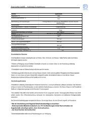
<strong>Paul</strong> <strong>Gothe</strong> Bochum<br />
GMU-Cascade <strong>Impactor</strong><br />
<strong>Johnas</strong> II<br />
For In-Stack<br />
PM 10 and 2,5<br />
Measurements<br />
(Emissions Monitoring)<br />
3 cut-off-classes:<br />
1. dae > 10 µm<br />
2. dae 2,5 bis 10 µm<br />
3. dae < 2,5 µm<br />
� calibrated with mono- und<br />
polysize Particle<br />
� checked for their correctness<br />
in official control-programs<br />
according to the german and european guideline<br />
Developed by<br />
Gerhard-Mercator University Duisburg<br />
and contry-environment-office<br />
Nordrhein-Westfalen –Germany-<br />
Manufacturer: <strong>Paul</strong> <strong>Gothe</strong> Bochum
<strong>Johnas</strong> II page 2<br />
Instruction manual PM 10 / PM 2.5 - GMU-Cascade <strong>Impactor</strong> <strong>Johnas</strong> II<br />
for measurement of the emissions of fine dust in low range<br />
Cascade <strong>Impactor</strong> GMU-<strong>Johnas</strong> - developed for PM 10 / PM 2.5 in-stack measurements<br />
Preliminary Note<br />
With dust emissions, particular attention should be paid to the proportion of fine dust, which<br />
may considerably affect the quality of the air. Reference has to be made in this connection to<br />
the thoracic penetration, the low sedimentation velocity in the atmosphere and the concentration<br />
of heavy metals on small particles.<br />
For the above mentioned reason the total and the fine dust content of industrial waste gases<br />
have been limited by the Technical Instructions on Air Quality Control within the European<br />
Immission Control Act, in which fine dust refers to particles having diameters of 5 µm and/or<br />
10 µm. However, nothing has been stipulated as to how particle diameters have to be defined,<br />
what density the definition has to be based on and which method of measurement has<br />
to be applied.<br />
The German Guideline VDI 3491 Part 1 defines 19 different particle diameters. In combination<br />
with various units of quantity, such as the number, volume and mass, numerous ways<br />
are obtained for measuring and presenting the particle size distribution. For emission measurements,<br />
the aerodynamic diameter is suitable for defining the particle size. It describes the<br />
behaviour of gas-borne particles having a diameter of more than 0.5 µm. In accordance with<br />
European standards mass fractions should be used for describing the particle size distribution.<br />
The number of applicable methods of measurement is limited by the requirements of the<br />
measuring test to be solved. In general it is desirable to measure the particle size while the<br />
particle is still suspended in the gas. However most measuring instruments used for this purpose,<br />
such as those based on light scattering, diffusion batteries, electrostatic aerosol analysers<br />
and aerosol centrifuges, require sampling by means of the extraction probe, since the<br />
instruments cannot be used directly in the waste gas duct.<br />
It has been fond that measuring of particles larger than 3 µm is affected by parts of the dust<br />
being deposited on the walls of the probe and of the measuring instrument inlet. The application<br />
of these methods of measurement is therefore limited to particles below 3 µm. For emission<br />
measurements in industrial plants, the presence of particles smaller than 1 µm and up to<br />
100 µm is to be expected.<br />
Normally, the above mentioned aerosol instruments cannot be used in hot and chemically<br />
aggressive waste gases. Heavy cooling of the extracted sample gas stream is not allowed<br />
since condensation of the moisture and other substances carried along with waste gas could<br />
alter the particle size spectrum.<br />
According to the latest state of the art, cascade impactors are considered as suitable for the<br />
extraction and simultaneous fractionation of sample gas streams for the purpose specified in<br />
Guideline VDI 2066 Part 1. Moreover, they can be used directly in hot and chemically aggressive<br />
gases.<br />
Due to the new standards of ambient air quality PM 10 and PM 2.5, these particle size<br />
fractions should also be measured in emissions as combustion and industrial processes are<br />
anthropogenic sources of particulate matter in ambient air. Therefore, the johnas a sampling<br />
system for PM 10 / PM 2.5 in-stack measurements was designed and calibrated. The<br />
exhaust gas is isokinetically sucked into the cascade impactor through the inlet of the plane
<strong>Johnas</strong> II page 3<br />
filter device (VDI 2066 part 7) and the aerosol is fractionated in the particle size classes > 10<br />
µm, 10 - 2.5 µm and < 2.5 µm. Due to a relatively high volume flow (ca. 3.2 m³/h, depending<br />
on exhaust gas conditions), sampling times are kept short (for dust concentrations of 10<br />
mg/Nm³ only 30 min).<br />
When applying cascade impactors johnas in combination with gravimetric evaluation, it is<br />
possible to obtain the mass distributions related to the aerodynamic particle diameter. This<br />
is, however, no substitute for the measurement of the total dust content (TSP).<br />
Conversion to other particle measures can only be carried out in exceptional cases and with<br />
the help of additional information on further properties, such as mass density and particle<br />
shape factors of the dust.<br />
As with all aerosol measuring instruments, limits are set to the applicability of cascade<br />
impactors by the particle size range, the mass concentration of particles and the properties of<br />
the carrier gas. Depending on the condition of the gas, the particle properties, and the design,<br />
cascade impactors johnas will collect the particles and segregate them into three fractions<br />
-> PM 10, PM 10 and PM 2.5-. Coarser particles (larger than 10 µm) affect the fractionating<br />
process and separate often in the first cone (transition between sampling probe and<br />
first impactor stage).<br />
The use of the johnas is, of course, not limited to the applications described in this manual.<br />
Thus, for instance, impactors may be used in field of the process technology.<br />
1 Principle of the Method<br />
<strong>Impactor</strong>s make use of the different inertia of particles to fractionate the dust according to<br />
particle sizes. The basic impactor stage components are the nozzle and impact plate. When<br />
accelerated in the nozzle those particles which have sufficient inertia strike the impact plate<br />
where they are collected.<br />
The most important dimensions of the system as far as fractionation is concerned are the<br />
nozzle width D, the nozzle length L and the distance S between impact plate and nozzle.<br />
The cascade impactor <strong>Johnas</strong> consist of a series of impactor stages in which the particles<br />
are segregated according to their decreasing inertia, so that fractions of different particle size<br />
are obtained. The particles which are not retained in one of the impactor stages are collected<br />
in a backup filter arranged downstream of the impactor stages.<br />
It is very easy to find out the particle size range covered by the three fractions. Use the excel<br />
file, which you find in the delivery capacity. The separation efficiencies is a function of the<br />
particle sizes for the individual impactor stages of a cascade impactor. The probability of a<br />
specific size of particles being collected on the impact plate and retained there is reflected by<br />
the separation efficiency which is given by the product of the impaction and retention efficiency.<br />
The separation efficiency will only equal the impaction efficiency, if the retention efficiency is<br />
100%. The impaction efficiency depends on the flow field and particularly on the mobility of<br />
the particles. The flow field is mainly characterised by the S/D ratio and the Reynolds number.<br />
The particle movement in the flow is defined by the dimensionless Stokes number.<br />
The <strong>Johnas</strong> is developed according to the theory of Marple. VA. Marple and B. YH. Liu calculated<br />
the impaction efficiencies for different flow fields as a function of the Stokes number.<br />
According to these calculations the impaction efficiency for L/D > 0.25, 0.5 < S/D
<strong>Johnas</strong> II page 4<br />
mately 80% it rises with a very steep gradient as a function of the Stokes number continuing<br />
then with a decreasing gradient until reaching 100%.<br />
Because of the impaction efficiency rapidly rising with the Stokes number, the functional interrelation<br />
can be expressed more or less as a discontinuous function with the jump discontinuity<br />
being assigned to the median value St50. This causes a segregation into two fractions at<br />
the aerodynamic diameter<br />
The following theoretically derived values, which have also been experimentally confirmed<br />
for test aerosols, are indicated for various Stokes numbers.<br />
Median values of the Stokes number determined by experiments are used as a basis for the<br />
practical evaluation of impactor measurements while the cut diameter dae50 of an impactor<br />
stage is determined in accordance with equation.<br />
The influence of the Reynolds number on the median value St50 may be neglected within the<br />
range of 100 < Re < 3000.<br />
With very large Reynolds numbers (Re> 10000) deviation towards smaller Stokes numbers<br />
will occur. However, large Reynolds numbers should generally be avoided to prevent particle<br />
blowoff from the impact plate because of the high gas velocities.<br />
Deviations towards larger Stokes numbers, which have also been observed in experiments,<br />
occur with Reynolds numbers of less than 100.<br />
For details see Table 1-3 at the end of this description.<br />
2 Mode of Operation and Structural Components<br />
2.1 Mode of Operation<br />
A dust-Iaden gas flows through an extraction probe and a transition cone into the impactor<br />
where the dust particles are segregated according to their size and collected in the individual<br />
impactor stages. The dust particles which are not collected in the impactor stages are retained<br />
in a backup filter (see Figs. 1).<br />
To obtain sufficiency of dust, an adequate volume flow has to be passed through the impactor.<br />
Therefore in consideration to the specified Reynolds number range, several identical<br />
nozzles are arranged in parallel in an impactor stage (multi-nozzle impactor).<br />
As far as the volume flow is concerned, an impactor, must be operated in the defined limits,<br />
in accordance with its design and the calculated flow (see excel file). Moreover, the requirement<br />
of isokinetic sample gas extraction has to be met. Losses due to deposits of particles<br />
on surfaces different than the impact plates of the individual <strong>Impactor</strong> stages is well as losses<br />
due to particle bouncing and blowoff from the impact plates limited the use of the impactor<br />
(see table 1).
2.2 Components<br />
<strong>Johnas</strong> II page 5<br />
The cascade impactor consists of the following components which is manufactured from corrosion-proof<br />
titanium materials:<br />
Extraction Probe<br />
For adapting the gas velocity at the extraction probe inlet to the gas velocities prevailing in<br />
the waste gas duct, a set of exchangeable probes with different diameters is required.<br />
Transition Cone<br />
This part is required to provide a transition between the diameter of the extraction probe and<br />
the diameter of the first nozzle plate.<br />
<strong>Impactor</strong> Casing<br />
This casing is required for the accommodation of the impactor inserts which consist of the<br />
individual impactor stages, the sealing elements and the backup filter.<br />
<strong>Impactor</strong> Stages<br />
These consist of the nozzle plates and the impact plates (filter holder).<br />
The impact plates are arranged rectangularity to the direction of flow.<br />
The impact plates are either covered by suitable Munktell quartz fibre filter (collecting plates)<br />
or provided with a coating (adhesive agent), depending on the properties of the particles to<br />
be studied, on the gas composition, the gas temperature and the requirements of the subsequent<br />
analysis.<br />
Backup Filter<br />
This alter follows immediately after the last impactor stage and is to collect the particles that<br />
have not been retained in the impactor stages. Suspensions filters of the S category are<br />
used for this purpose (Munktell-filter).<br />
3 Measuring Arrangement<br />
The Arrangement of the measuring equipment must comply with the requirements of the application.<br />
The following contains a description of a typical installation for a measurement by<br />
impactor in accordance with Guideline VDI 2066 Part 1.<br />
3.1.1 Sampling Equipment<br />
All gas carrying parts are of corrosion-proof titanium<br />
Extraction Probes effective diameter 3 to approximately 16 mm, straight probe design.<br />
Cascade <strong>Impactor</strong> consisting of impactor casing and impactor insert, selection in accordance<br />
with the application.
<strong>Johnas</strong> II page 6<br />
3.1.2 Equipment for Sucking, Adjusting and Measuring the Sample Volume Flow Rate<br />
Gas Drying Column Silica gel packed, minimum column diameter 70 mm, height of the<br />
packing approximately 300 mm.<br />
Condensate Trap if necessary, the drying column is preceded by a gas cooler.<br />
Suction Equipment e.g. corrosion-proof pump; volume flow rate approximately 4 m³/h at<br />
400 mbar on the intake side.<br />
Suction Tube inside diameter approximately 8 mm, outside diameter for lengths of<br />
more than 2 m at least 20 mm; in order to prevent the condensate<br />
from flowing back into the cascade impactor, it may either be necessary<br />
to provide a heating system for the suction tube or to install a<br />
condensate trap.<br />
Gas Volume Meter gas volume meter for measuring the passed gas volume; nominal<br />
capacity 6 m³/h, calibration tolerance 2%, permissible depression with<br />
reference to the atmosphere 200 mbar.<br />
Rotameter for monitoring the sample volume flow rate.<br />
alternatively:<br />
Gas Volume Meter gas throttle device (orifice or nozzle), design and use in accordance<br />
with DIN 1952 or Guideline VDI/ VDE 2040 Part 2.<br />
Temperature Measuring Devices for measuring the gas temperature at the gas volume meter<br />
and the tapping point.<br />
Differential Pressure Measuring Device e.g. U-tube manometer for measuring the differential<br />
pressure in the gas volume meter and in the waste gas duct<br />
with reference to the atmospheric air pressure.<br />
Time Measuring Device for measuring the sampling period.<br />
Barometer for measuring the atmospheric air pressure at the sampling point.<br />
Shutt off Valves and Control Valves for coarse and fine adjustment of the sample gas flow<br />
rate.<br />
Junction Tubings the junction tubing’s between the individual equipment parts must be<br />
corrosion-proof, flexible and heatable, if necessary.<br />
3.1.3 Equipment for Measuring the Gas Velocity and the Gas Composition<br />
Gas Velocity Measuring Device Prandtl tube in combination with a micromanometer.<br />
Gas Analysers (if necessary) for determining the main components of the waste gas at<br />
the tapping point in connection with the determination of<br />
the gas density and viscosity; e.g. CO2,O2, H2O depending<br />
on the application.
<strong>Johnas</strong> II page 7<br />
3.1.4 Accessories for the Pretreatment and Posttreatment of the Collecting Plates in<br />
the Laboratory<br />
Scales minimum resolution 0.1 mg; installation, if possible, in a room with<br />
constant temperature and humidity (recommended values: temperature<br />
approximately 20°C, constant relative humidity within the range<br />
of 50 to 60%).<br />
Drying Chamber for heating up the collecting plates to approximately 250°C<br />
Furnace only necessary if temperatures above 250°C are required.<br />
Desiccator for equilibrating the samples.<br />
Scale pans for accommodating the collecting plates made, for instance, of Aluminium<br />
foil.<br />
Transport Container for the accommodation of the impactor inserts or impactor stages.<br />
3.1.5 Working Materials<br />
Collecting Plates can used with Munktell quartz-fibre filter. Stamps accessories, for the<br />
hole in the middle is in the delivery capacity.<br />
Backup Filter for the collection of particles that have not been retained in the impactor<br />
stages, e.g. quartz fibre filter of the S category (Munktell).<br />
Adhesive Agent for improving the adhesion of the dust particles: high-vacuum grease<br />
Apiezon L or Apiezon H.<br />
Drying Agent silica gel with colour indicator.<br />
3.2 Measuring Setup<br />
As far as the connection to the supply system and the equipment of the measuring site are<br />
concerned, reference is made to Guideline VDI 2066 Part 1. The sampling ports should be<br />
adequately dimensioned in accordance with the impactor type and the wall thickness of the<br />
waste gas duct.<br />
The cascade impactor has to be equipped with a straight inlet probe (acc. to VDI 2066,<br />
page 7) and to be installed in the waste gas duct so that it will face the gas stream.<br />
When arranging the suction equipment after the gas volume meter, the volume flow can be<br />
controlled by adding ambient air. By adding ambient air, the test gas can be cooled in the<br />
condensate chamber at the same time.<br />
Unlike the measuring setup it may be necessary under special circumstances, such as in<br />
oversaturated waste gases, to locate the cascade impactor outside the waste gas duct. For<br />
this purpose the impactor is headed by a suction tube, an elbow and an extraction probe.<br />
These have to be heated up, if necessary. With this arrangement, particles may get deposited<br />
on the walls of the extraction system thus affecting the fractionating separation in the<br />
impactor.
4 Preparation and Performance of the Measurement<br />
<strong>Johnas</strong> II page 8<br />
4.1 Selection and Pretreatment of the Collecting Plates and the Backup Filter<br />
A suitable set of collecting plates and backup filters have to be chosen and pretreated for<br />
each measurement.<br />
The collecting plates (filter holder) and the backup Filter is in titanium, so that is inert in respect<br />
of the constituents of the sample gas stream so as to avoid changes in the mass<br />
caused by chemical reactions. Titanium collecting plates which have been pretreated with<br />
Munktell quartz fibre filter have proven successful in practice for many applications. It is advisable<br />
to check the materials considered adequate in a preliminary test for changes in mass<br />
and thus to ensure that the material most suitable for the purpose will be selected.<br />
To avoid weight losses, the filter of the collecting plates and the backup filter, both made of<br />
quartz fibre, are each accommodated in filter holder and placed in the drying chamber where<br />
they are left for at least 1 hour to dry at a temperature of 180°C. If the cascade impactor is to<br />
be used at temperatures above 180°C, care should be taken to subject the collecting plates<br />
and the backup filter to a pre- and posttreatment at a reasonably higher temperature in order<br />
to avoid losses of binding agent etc. during the measurement. After the heat treatment, the<br />
filter holder containing the collecting filters and the backup filter have to be cooled in the desiccator<br />
for at least 1 hour before weighing. After weighing they have to be kept in Petri<br />
dishes, well protected from dust.<br />
The introduction of the weighed collecting filter holder into the prepared impactor inserts<br />
should preferably be done in the laboratory, since adequate rooms for this sort of work are<br />
very often not available on the site where the measurements have to be carried out. The<br />
number of measurements to be made should not exceeds the number of available impactor<br />
filter holder. The filter holder with the filter can easy exchanged in situ. Utmost caution is advised<br />
for the transport of the prepared filter holder and backup Filters to the site and of the<br />
dust-laden plates and backup filters back to the laboratory.<br />
The individual collecting filter holder and backup filter holder must allow easy identification.<br />
Since they themselves must not be marked (change in weight!), it is advisable to mark the<br />
pans with the set and the stage numbers. The right order should be strictly adhered on insertion<br />
and withdrawal.<br />
4.2 Pretreatment of the lmpactor Inserts<br />
The individual components of the impactor insert have to be cleaned in the ultrasonic bath<br />
before each measurement. Normal tap water to which some detergent or alcohol has been<br />
added is generally sufficient as cleaning agent. When tap water is used carefully rinsing with<br />
distilled water is necessary to avoid calcareous deposits.<br />
After drying, the nozzle plates, collecting plates (filter holder) and gaskets have to be<br />
checked for appreciable damage. Care should be taken during the assembly to prevent the<br />
gaskets, collecting plates and backup filter from being damaged.<br />
4.3 Performance of the Measurement<br />
4.3.1 Measurement Planning<br />
Before carrying out, the measurement should be thoroughly planned in accordance with<br />
Guideline VDI 2066 Part 1. This includes the determination of the number and the location of<br />
the sampling points. Unlike the tubular filter device, which is used for measuring the total
<strong>Johnas</strong> II page 9<br />
dust content, the impactor does not permit free selection of the gas flow rate once the probe<br />
diameter has been established. On the contrary, the gas flow must be kept constant during<br />
the measurement (sampling). This means that one measurement can only cover sampling<br />
points of approximately identical gas velocity (deviations of +30% are permissible) and that<br />
grid measurements require several measuring operations if there are significant differences<br />
in the velocity distribution.<br />
To calculate the gas flow rate use the excel file, which is in the delivery capacity. Set in all<br />
necessary data of the duct and gas specification and see the proposed nozzle diameter. If<br />
the Reynold Number between 100 and 3000 the theory of the impaction is valid and the plates<br />
contents the particle according to the shown cut offs.<br />
If the proportion of particles having a diameter of more than 10 µm is expected to exceed<br />
approximately 15% (by mass), it is necessary to reduce the sampling period, to prevent an<br />
overload of the first stage. Waste gas dust contents of more than 100 mg/m³ are indicative of<br />
a considerable proportion of particles having a diameter of more than 10 µm.<br />
4.3.2 Waste Gas Data<br />
To permit the adjustment of approximately isokinetic sucking conditions it is necessary to<br />
determine the waste gas velocity at the established sampling points.<br />
The differential pressure may, for instance, be measured with a Prandtl tube in combination<br />
with a micromanometer from the company <strong>Paul</strong> <strong>Gothe</strong> (see: www.paulgothe.de). The density<br />
has to be calculated from the pressure, temperature, gas composition and the molar masses<br />
of the gas components.<br />
For the evaluation of the results of the impactor measurements it is necessary to know the<br />
viscosity of the waste gas. Frequently the viscosity of the air at the corresponding temperature<br />
of the gas can be used in the calculation because the major part of the waste gases<br />
consists in nitrogen and oxygen.<br />
To calculate the flow rate through the impactor use the excel file. Have a look at the Reynold<br />
number, shown in the excel-file.<br />
4.3.3 Handling the Cascade <strong>Impactor</strong> during Operation<br />
Dust measuring by means of an impactor is done in a similar way to dust measuring by<br />
means of a tubular filter device. The individual working steps are described below.<br />
When introducing the impactor sampling system into the waste gas duct, care should be<br />
taken that the dust adhering to the walls of the duct or deposited in the duct does not enter<br />
the probe. Moreover, any flow through the impactor caused by the difference between duct<br />
and ambient pressure must be avoided. The shut-off valve has to be kept tightly closed for<br />
this purpose until after the start-up of the sucking system.<br />
It is advisable, particularly for measurements in the waste gas having a temperature which is<br />
only slightly above the dew point, to preheat the sampling system so as to ensure that the<br />
temperature in the impactor does not drop below the dew point temperature. Preheating can<br />
in general be carried out outside the duct, in a furnace, or by keeping the impactor for a sufficiently<br />
long period in the waste gas stream before performing the measurement. The opening<br />
of the probe must be adjusted in the direction of the gas flow to prevent particles from<br />
entering the impactor before the measurement starts.
<strong>Johnas</strong> II page 10<br />
During the sucking procedure (sampling period), the opening of the probe at the individual<br />
sampling points has to face the gas flow.<br />
The sampling period of the impactor should be chosen to ensure collection of a sufficient<br />
mass of dust per impactor stage to permit weighing with sufficient accuracy and to prevent<br />
overloading of the stages.<br />
After each measurement or when moving the sampling system to another sampling point, the<br />
shut-off valve has to be closed before the suction unit is switched off in order to avoid reverse<br />
flow through the impactor. Then the probe has to be aligned with the direction of the<br />
gas now and removed from the duct. The impactor or the impactor insert respectively is kept<br />
away from the measuring system and stored in a dust free atmosphere until evaluation. Drying<br />
and re-weighing of the collecting plates and the backup Filter is done under the same<br />
conditions as the determination of the mass of the unloaded components. The drying temperature<br />
of the loaded collecting plates and the backup filter can be limited due to possible<br />
changes of the collected dust.<br />
Deposits of dust in the sampling train have to be extracted and considered for the evaluation.<br />
The collecting filter holder of the individual impactor stages and the backup filter holder<br />
should be checked again before and after re-weighing in order to prevent measuring or interpretation<br />
errors:<br />
- A change in the colour of the backup Filter may be due to condensate having flown back<br />
to the backup filter either during sampling or immediately afterwards or due to the temperature<br />
in the impactor having dropped below the dew point during the measurement.<br />
This lets the particle size distribution in the result appear to have been shifted towards<br />
smaller particle diameters.<br />
- If dust deposits are not clearly delimited on the collecting plates, the respective collecting<br />
plate may have been overloaded. This may result in a shifting of the particle size distribution.<br />
An Figure in the chapter: “hints during sampling” shown collected dust at the different<br />
collecting plates.<br />
If the particle size distribution is unknown, the decision whether the impactor can used or not<br />
can be taken after the first measurement. The decision can be taken on visual assessment of<br />
the collecting plates.<br />
4.3.5 Treatment of the lmpactor Inserts<br />
The impactor inserts have to be handled with utmost care. Containers with compartments for<br />
the individual accommodation of several impactor inserts have proven successful for transport.<br />
Since the nozzle plates are not firmly installed, the containers should be transported in<br />
a vertical position. They must not be tilted nor exposed to vibration or shocks. Installation and<br />
dismantling of impactor inserts has to he carried out at a location without draught. It has to be<br />
ensured that the collecting plates and the backup filters do not get damaged or contaminated.<br />
If no laboratory is available at the measuring site, the used impactor inserts have to be returned<br />
with great caution to the laboratory.
4.3.6 Evaluation of the lmpactor lnserts in the Laboratory<br />
<strong>Johnas</strong> II page 11<br />
After sampling the collecting plates and backup Filters must again, as in the pretreatment<br />
procedure, be put individually into their respective marked pans, and placed in the drying<br />
chamber. Before weighing they have to be kept for 1 hour at a temperature of 180°C and<br />
cooled down in the desiccator.<br />
Loose dust lying on the plates of the individual stages of the impactor has to be included on<br />
weighing. If sufficient dust hits been collected in the impactor stages, a balance with a readout<br />
precision tolerance of 0.1 mg may be used.<br />
4.3.7 Evaluation of the first cone<br />
For evaluation of particle larger PM 10 it is necessary to determine the dust mass collected in<br />
the first cone (transition between sampling probe and first impactor stage) by differential<br />
weighing. A weighing accuracy of 0.1 mg should be aimed at. If differential weighing is not<br />
possible, the dust collected has to be transferred quantitatively from the cone to a weighing<br />
pan. If a dust of more than 20 mg has been collected in the cone, it will mostly be sufficient to<br />
transfer the dust from the cone to the weighing pan by means of a brush.<br />
If the dust mass is small, the cone has to he washed out. For this purpose the outside has<br />
first to thoroughly cleaned. If necessary, acetone has to be used to remove the grease from<br />
the threads of the lid. After this, the cone is washed out with approximately 50 ml of distilled<br />
water or methanol and rinsed with a further 25 ml of distilled water or methanol.<br />
The dust mass can be determined by filtering the suspension through a membrane filter having<br />
a pore size of approximately 1 to 2 µm. If the suspension contains soluble substances, it<br />
has to be evaporated for mass determination.<br />
4.3.8 Measurement of Gases with High Water Vapour Content<br />
If the waste gases contain a high proportion of water vapour, the determination of the gas<br />
flow rate through the cascade impactor may be affected by errors occurring on measuring<br />
the water vapour content. If the gas volume is measured by means of a volume meter which<br />
is headed by a drying column, exact measurement of the water dew point is necessary to<br />
minimise the error occurring on dry to moist gas volume conversion, this is particularly important<br />
with water dew points of more than 80°C.<br />
If the waste gas temperature is only slightly above or equal to the dew point temperature, the<br />
cascade impactor has to be heated up in the heater for the cascade impactor to a temperature<br />
approximately 50°C above that of the waste gas before installation into the waste gas<br />
duct. After installation the cascade impactor needs time to adapt the temperature to that of<br />
the waste gas. Normally this will take about 15 minutes. In this way condensation is prevented<br />
in the cascade impactor.<br />
By using a heated gas throttle device in combination with a heated suction tube, it is possible<br />
to measure the volume flow rate through the cascade impactor including the water vapour<br />
content directly.<br />
For oversaturated waste gases containing droplets it is normally necessary to use heated<br />
sampling equipment with a cascade impactor installed outside of the waste gas duct. With<br />
this arrangement the droplets dry up forming nuclei of dissolved and undissolved impurities<br />
which are separated as considerably smaller particles in the corresponding cascade impactor<br />
stage. Due to increased separation of coarse particles in the sampling train, the use of this<br />
arrangement is limited to particles having a diameter of less than 4 µm.
4.3.9 Selection of Suitable Sampling Probes<br />
<strong>Johnas</strong> II page 12<br />
The volume flow rate of a cascade impactor can not be selected freely. It does, however,<br />
influence the location of the particle size cut of the individual impactor stages. Therefore, the<br />
impactor must be operated with from the excel file calculated constant volume flow rate during<br />
measurement. To achieve an approximately isokinetic sample gas stream it is necessary<br />
to have a set of suitable sampling probes. The appropriate probe diameter is determined by<br />
the Excel-file as a function of the required sample volume flow rate and of the waste gas velocity,<br />
in accordance with the following equation:<br />
4 •V<br />
d =<br />
π • w<br />
d = diameter of the sampling probe in m<br />
V = sample volume flow rate at operating conditions in m³/s<br />
W = waste gas velocity in m/s.<br />
From the set of available sampling probes the one with the cross-sectional area coming most<br />
closely to the dimensions of the calculated probe should be chosen.<br />
It is advisable to use the next smaller size of probe in order to have an increasing of the gas<br />
volume flow at the nozzle. This give less errors. In practice, probes with cross-sectional areas<br />
derated by the factor 1 have shown good results the volume flow rates. The probe diameter<br />
should, however, not be smaller than 3 mm.<br />
Straight and curved probes are available for the <strong>Johnas</strong> cascade impactor, the latter under<br />
the name of "gooseneck probes". Due to increased coarse particle separation in a curved<br />
probe, this type of probe should only be used for particles with diameters of less than 4 µm.<br />
4.3.10 Calculating the Sample Volume Flow Rate<br />
Use the excel-file to calculate the sample flow rate.<br />
It has to be corrected according to the gas conditions in the gas volume meter by the following<br />
equation:<br />
TZ<br />
• Pm<br />
Vz<br />
= Vm<br />
• • S<br />
Tm<br />
• PZ<br />
Vz = volume flow rate in the gas volume meter m³/s<br />
Vm = sample volume flow rate at operating conditions in m³/s<br />
Tz = temperature of the gas in the gas volume meter in K<br />
Tm = temperature of the gas at the measuring point (waste gas duct) in K<br />
Pz = absolute pressure in the gas volume meter in bar<br />
Pm = absolute pressure at the measuring point (waste gas duct) in bar<br />
S = dry to humid gas volume ratio<br />
At the beginning Tz and Pz are unknown. Estimated values have to be used in the calculation<br />
to achieve a first approximation. Or the basis of these estimated values, the volume flow rate<br />
of the impactor is first of all adjusted. After a sufficient long measuring period the values obtained<br />
at the beginning of the measurement may be used for further correction.<br />
With short measuring periods it is advisable to stick to the gas volume meter setting based<br />
on the estimated temperature and pressure values, otherwise the adjusting of the volume<br />
flow rate will take up to large a proportion of the measuring period.
<strong>Johnas</strong> II page 13<br />
The volume flow rate V, can be checked by means of a variable area flowmeter.<br />
4.3.11 Estimating the Measuring Period<br />
The measuring period may be estimated from the desired impactor load and the dust content<br />
of the waste gas in accordance with the following equation:<br />
T =<br />
q<br />
f<br />
m<br />
•V<br />
m<br />
=<br />
q<br />
tr<br />
m<br />
•V<br />
Z<br />
T = measuring period in s<br />
M = desired impactor load in mg<br />
Vm = sample volume flow rate under operating conditions in m³/s<br />
VZ = volume flow rate through the gas volume meter in m³/s<br />
qf = dust mass concentration in the waste gas related to the operating conditions in mg/m³<br />
qtr = dust mass concentration in the dry gas, related to the condition at ambient temperature<br />
and ambient pressure in mg/m³.<br />
The load capacity of the cascade impactor depends on the particle size distribution. The<br />
measuring periods for narrow particle size distributions may be considerably shorter due to<br />
possible overcharging of individual stages. If necessary, that is, for instance, if the dust content<br />
is unknown, the measuring period has to be estimated by a visual assessment of the<br />
dust-Iaden collecting plates after the first use. This requires some experience. It is more advisable<br />
to evaluate the first measurement exactly to allow purposeful application of the impactor<br />
for further measurements.<br />
5 Evaluation of the Measured Data and Calculation<br />
5.1 General<br />
The mass of the dust which has been impacted on the individual collecting plates of the impactor<br />
and which is determined by weighing is the direct result of the impactor measurement.<br />
At the first collecting stage –PM10 filter holder- are collected particle with dae50 value greater<br />
than 10µm. The summary mass of the second preceding stage –PM 2.5 filter holder- and the<br />
backup filter enclosed 50 % of particle with dae50 value smaller as 10µm, named PM 10. The<br />
mass of the backup filter enclosed 50 % of particle with dae50 value smaller as 2.5 µm, named<br />
PM 2.5.<br />
The cut-off curve is shown in figure 2-3.<br />
The mass of the second impactor stage –PM 2.5 filter holder- collected defined particle size<br />
intervals between PM 10 and PM 2.5. The actual cut off can read out from the excel file.
6 Performance Characteristics and Application<br />
<strong>Johnas</strong> II page 14<br />
The performance characteristics mentioned below were determined for the johnas round<br />
nozzle impactors, if the following minimum requirements are met:<br />
- ratio S/D > 1.5<br />
- ratio L/D> 0.25<br />
- number of nozzles per stage: the Reynolds numbers for the flow in the nozzle jets must<br />
be within the range of 100 < Re < 3000. The Excel-file calculate the Reynold numbers.<br />
Therefore the operator can easy controlled the operating conditions.<br />
- collecting plate material: quartz fibre material with adequate adhesion properties to retain<br />
particles<br />
- suitable design to minimise "wall losses"<br />
6.1 Particle Size Range<br />
The median value of the aerodynamic diameter of the last stage of the impactor is about 2.5<br />
µm. The impactor is followed by an S-class backup filter which is characterised by its high<br />
collection efficiency for particles of less than 1 µm. In this way almost all the particulate matter<br />
is collected in an impactor.<br />
For larger particle sizes the application of the impactor is limited because of an increasing<br />
error rate in the case of<br />
- non-isokinetic sampling<br />
- deposits on surfaces which are not included in the evaluation, particularly in the inlet<br />
cone (transition between sampling probe and first impactor stage)<br />
- insufficient adhesion to the collecting plates causing particle bouncing or blowoff.<br />
The impactor <strong>Johnas</strong> is calibrated with monodisperse aerosols. For an accuracy required in<br />
practice it has been found that the mass fraction of the particles larger than 10 µm must not<br />
exceed 15%.<br />
If the proportion of particles larger than 10 µm exceeds the above percentage, it is advisable<br />
to use the impactor only for a short period so that bouncing particles of the first page will not<br />
get into the second and last stage.<br />
6.2 <strong>Impactor</strong> Load<br />
High <strong>Impactor</strong> loads permit, in general, better evaluation by reducing the influence of weighing<br />
errors. The range of 4 to 10 mg per stage should be aimed.<br />
If the chemical composition of the dust is known, low impactor loads will suffice provided a<br />
volumetric analysis procedure of adequate accuracy is applied. Table 1 shown the operating<br />
conditions. The <strong>Johnas</strong> can used also by high dust load over 100 mg/m³. An higher dust load<br />
does not restrict the application of the impactor. The first stage may be checked. For the interpretation<br />
of PM 10 and PM 2.5 is not the weighing of the first stage necessary.
6.3 Dust Content<br />
<strong>Johnas</strong> II page 15<br />
The limits of the waste gas dust content between which an impactor can be used are given<br />
by the load capacity and the requirement of a reasonable measuring period. In addition, the<br />
particle size distribution may have influence on the permissible limits of the waste gas dust<br />
content.<br />
The <strong>Johnas</strong> cascade impactors is special developed for low dust range and can be used<br />
within the dust content range up to 100 mg/m³ (see Table 1). Higher dust load can measured<br />
too, but the stages must controlled very well whether the high dust load happened influence<br />
of the impaction. The measuring period must set shorter, down to a period of about 3 minutes.<br />
Measurements of considerably lower duration should be avoided since the adjustment<br />
of the volume flow rate would take up to large a proportion of the measuring period.<br />
To achieve the optimum impactor load when handling gases with a dust content of about 1<br />
mg/m³, the measurement must last 5 h. However, useful results can already be obtained with<br />
loads of 10 mg and measuring periods of 30 min.<br />
6.4 Temperature Range<br />
The <strong>Johnas</strong> cascade impactors are available for waste gas temperatures of up to 400°C. In<br />
addition to the permissible maximum working temperature, the temperature resistance of the<br />
collecting plate material has to be taken into account. Glass fibre papers loose some of the<br />
binding agent at high temperatures which results in a loss in strength. Their suitability for<br />
application above 300°C must therefore be tested. The Munktell-quartz fibre filter can used<br />
up to 900°C. In this case, it is very important to pre-heat the Munktell-quartz fibre filter!<br />
6.5 Waste Gas Velocity<br />
The range of the velocities prevailing in waste gas ducts where cascade impactors can be<br />
used is limited by the volume flow rate of the cascade impactor and by the probe diameter.<br />
6.6 Reproducibility and Uncertainty<br />
The reliability of the measuring method can be assessed by the reproducibility’s and uncertainties<br />
of the undersize total.<br />
7 Possible Errors and Error Assessment<br />
When carrying out the measurements with the measuring equipment, errors may occur,<br />
which will affect the calculation of the median value of the aerodynamic diameter and the<br />
determination of the undersize total to a different degree. For the following error assessment<br />
it is understood that the impactor-specific parameters (dimensions and number of nozzles of<br />
the individual impactor stages and Stokes number) are known to a sufficient degree of accuracy<br />
and that they do not vary during the measurement.<br />
The measuring errors and their influences on the performance characteristics can be estimated<br />
as follows:<br />
a) Dust masses on the individual impactor stages and on the backup filter, if any errors on<br />
dust mass determination may be brought about by:<br />
- Improper handling of the impactor (condensate formation due to the temperature drop<br />
below the dew point, mechanical damage of the collecting plates, displacement of impacted
<strong>Johnas</strong> II page 16<br />
particles due to overloading of individual impactor stages, insufficient adhesion of the particles<br />
due to the use of unsuitable collecting plates<br />
- Influences of the waste gas on the collecting plates (mass increase or decrease due<br />
to sorption and chemical reaction of the plate material with the individual components of the<br />
waste gas<br />
- Thermal instability of the collecting plates (loss of binding agent, insufficient conditioning,<br />
wrong heating temperature and heating period<br />
- Weighing errors (limited read-out accuracy of the balance used)<br />
When handling the impactor properly and selecting the right collecting plates in accordance<br />
with the instructions given in this specification, the error rate for the determination of the<br />
mass of the individual impactor stages and the backup filter, if any, can be limited to + 0.5<br />
mg. This subjects the undersize total and the oversize total to an error of approximately ± 3<br />
%.<br />
b) Waste gas composition<br />
Errors in the determination of the waste gas composition affect the calculation of the gas viscosity<br />
and the conversion of the volume of the dry gas (determined by means of a volume<br />
meter) to the corresponding humid gas volume at operating conditions. If the volume fraction<br />
of the individual constituents is determined with a relative error of less than 5%, the influence<br />
on the gas viscosity will be negligible.<br />
If the proportion of water vapour in the waste gas is less than 50%, it can be determined with<br />
a relative error of +2%. This results in a relative error of + 1% for the determination of the gas<br />
volume passing through the impactor. With higher water vapour proportions the volume<br />
should be determined by means of a meter run with a gas throttle device.<br />
c) Temperature of the waste gas relative error of approximately ± 0.5%<br />
d) waste gas pressures<br />
static pressure: relative error of approximately ± 0.2%<br />
dynamic pressure: relative error of approximately ± 10%,<br />
e) Sample gas volume flow rate – measured by means of a gas volume meter<br />
relative error of approximately ± 2%<br />
f) Temperature of the sample gas volume meter flow rate in the gas volume meter and at<br />
the gas throttle device<br />
relative error of approximately ± 0,5%<br />
g) Pressure of the sample gas volume flow rate in the gas volume meter at the gas throttle<br />
device<br />
absolute pressure relative error of approximately ± 2%<br />
differential pressure relative error of approximately ± 2%<br />
h) Measuring period
<strong>Johnas</strong> II page 17<br />
Errors in the determination of the measuring period are normally negligible. With extremely<br />
short measuring periods (less than 3 min) a relative error of time of 5% has to be<br />
reckoned with because of the adjustment of the volume flow rate.<br />
8 Maintenance and Check of the Measuring Equipment<br />
8.1 Maintenance carried out at the Laboratory<br />
Each time the impactor has been used it should be carefully cleaned. This applies particularly<br />
to the threads of the impactor casing which has to be cleaned with a fine wire brash of<br />
brass. This will help to prevent the threads from getting jammed during operation due to contamination.<br />
The nozzle plates have to be cleaned in the ultrasonic bath and checked for damage by visual<br />
inspection each time they have been used. Periodical examination of the nozzle plates<br />
under the microscope is recommended.<br />
To prevent the measuring accuracy from being affected by corrosive waste gas components,<br />
the calibration of the gas volume meter or of the gas throttle device as well as of the temperature<br />
and pressure measuring instruments should be checked at pre-set time intervals.<br />
8.2 Checking of the Measuring Equipment before Use<br />
Care has to be taken when installing or replacing an impactor insert that the dirt deposited on<br />
the impactor components does not get onto the impactor insert.<br />
The complete measuring system has to be checked for leakage before starting the measurement.<br />
For this purpose the opening of the probe has to be closed with a stopper and a<br />
negative pressure of about 150 mbar to be produced in the measuring system. This is about<br />
three or four times the negative pressure expected during operation. If neither the variable<br />
area flowmeter nor the gas volume meter indicate a volume flow, the measuring system is<br />
regarded as non-leaking.<br />
The silica gel packing of the drying column has to be exchanged in due time (watch the colour<br />
of the indicator) and the condensate trap, if any, to be emptied.<br />
9 Applications<br />
The <strong>Johnas</strong> cascade impactors are well suited for determining the particle size PM 10 and<br />
PM 2.5 in flowing gases. They can be installed in any position, that is in vertical, inclined or<br />
horizontal waste gas ducts.<br />
10 Excel-file<br />
As explained above, the separation-diameters d(ae)50 of a <strong>Impactor</strong> dependent of the duct gas<br />
conditions. The cut off steps PM 10 and PM 2.5 is calculated for a quite certain operating<br />
condition (see table 1). So that these cut off diameter don't postpone themselves, if itself the<br />
duct gas conditions changed, e.g. temperature and pressure in the duct as well as water vapour<br />
and gas composition, the gas flow rate must set accordingly through the Impaktor. For<br />
the fast, exact calculation, the included Excel-file, in which the measured duct gas conditions<br />
are set in, calculate the gas flow rate. This gas flow rate must be used to guarantee the cut<br />
off diameters 10 µm and 2.5 µm.
Short instruction<br />
<strong>Johnas</strong> II page 18<br />
The impactor’s handling in principle works like the one of the plane filter heading device, just<br />
as the impactor is in principle operated with the same peripheral devices (sucking-in probe<br />
for isokinetic sampling as well as bent, nozzles, suction tubes, etc..).<br />
Cleaning<br />
The cleaning of the impactor is carried out like the one of the plane filter heading.<br />
Filters<br />
For the impactor’s operation Munktell quartz fibre filters MK 360, Ø 50 mm are designed.<br />
Back-up Filters<br />
The fully cured quartz fibre filter is inserted as usual into the filter holder (I) and fixed by the<br />
fixing ring (1).<br />
Filters of the PM 10 and PM 2.5-Stage<br />
The fully cured quartz fibre filters are punched out with the help of the provided tool into<br />
which the filter holders (D and G) are inserted and fixed with the fixing ring.<br />
Weighing<br />
If the filters’ weighing takes place before or after the sampling including the filter holders,<br />
measuring adulterations can be prevented which might, for example, occur through losses of<br />
dust mass due to the withdrawal of the filter from the filter holder. The weighing takes place<br />
after the acclimatisation of the filters under constant temperature and air humidity by a balance<br />
with a resolving power as high as possible.<br />
Assembly<br />
Assemble the individual parts (see figure 1) according to the described order. Employ seal Di<br />
14 under and Di 15 over the plane filter holder (see figure 6). These seals are highly important.<br />
Seal Di 45 is inserted above the first cone and seals the Cover upward. The thread can<br />
be sealed with a teflon tape when required.<br />
The seals are used according to figure 6.<br />
Cone (B)<br />
PM 10-nozzle plate (C)<br />
PM 10-impaction plate (E)<br />
with filter holder and fixing ring (D + d)<br />
PM 2.5-nozzle plate (F)<br />
PM 2.5-impaction plate (H)<br />
with filter holder and fixing ring (G + g)<br />
Back-up filter holder and fixing ring (I + i)<br />
Exit (J)<br />
Cover (K)<br />
Operation<br />
The included Excel program, into which the operational data such as the waste gas temperature<br />
and composition etc. are entered, determines the proper sucking-in probe for the isokinetic<br />
sampling. It also determines the flow rate with which the impactor is to be operated<br />
under the appropriate conditions.
Hints for the Sampling:<br />
Isokinetic suction:<br />
<strong>Johnas</strong> II page 19<br />
an equal suction rate will rarely be possible. Usually the nozzle diameter suggested by the<br />
Excel file will not be available. However, there should be available a nozzle set with 1 mm<br />
steps. The errors that occur with a high suction rate are smaller than those with too low a<br />
rate. The separation diameters depend on the rate inside the impactor. Therefore, the suction<br />
rate can be kept only through the selection of the nozzle. The rate inside the impactor<br />
must never be modified , including the suction rate. The nozzle with the second smaller diameter<br />
is selected, except the difference from the next bigger diameter is clearly smaller.<br />
Thus the rate at the nozzle point increases and effects a faster suction. The less the selected<br />
nozzle differs from the one prescribed by the Excel file, the more isokinetic requests are fulfilled.<br />
If the temperature or the pressure or generally the density of the gas changes, the rate<br />
inside the impactor must again be calculated. In this case the suction rate must also be modified.<br />
This process will always generate errors. The specialist on the spot must decide which error<br />
is of greater significance. With particles smaller than 5 µm derivations from isokinetics can be<br />
neglected. The position of the separation diameter is more important. In the case of modification<br />
of the density the rate inside the impactor should be adapted. This is the only way to<br />
make a statement at all. If the separation diameters shift too strongly, an analysis is impossible.<br />
VDI guideline 2066, part 10, delivers useful information that contributes to a decision.<br />
Analysis:<br />
All collecting plates can be used for the sampling. The total of the selecting plate PM 2.5 and<br />
the back-up filter is the so-called PM 10-fraction. The back-up filter contains the so-called PM<br />
2.5-fraction.<br />
If also those particles bigger than PM 10 are to be considered, the particles on the first filter<br />
plate and the deposits inside the cone are to be weighed out together.<br />
The single filter plates are conditioned and treated according to the measurement of VDI<br />
2066, part 10.<br />
Particles inside the Input Cone:<br />
With total dust measurements according to VDI 2066, sheet 7, there are usually no deposits<br />
that can be perceived inside the input cone of the filter heading device. The mass of the adherent<br />
particles is not important. This is clearly different when sampling with the GMU cascade<br />
impactor <strong>Johnas</strong>. The flow inside the input cone causes increased particle separation<br />
on the wall. If exclusively the PM 10- and PM 2,5-fractions are to be determined, the particles<br />
inside the cone can remain unconsidered as long as the deposits do not influence the flow<br />
inside the cone. In case of the development of deposits which reach far into the cone, also<br />
particles with a small aerodynamic diameter will stick to these deposits and thus will question<br />
the whole measurement. However, this will rarely be the case. Usually the cone will be covered<br />
with a thin dust layer. This dust layer contains only particles bigger than PM 10.<br />
If the fraction bigger than PM 10 is also to be determined, the particles adherent to the cone<br />
must be added to the filter of the first stage plate. Therefore, the cone is rinsed with alcohol<br />
and the suspension of alcohol and particles is filtered by a standard filter. Filtering can be<br />
accelerated via a nutsch with a vacuum. Subsequently, this filter is dried and treated in accordance<br />
with VDI 2066 part 10.<br />
Sampling Time:<br />
The sampling duration can deviate clearly from the half-hour sampling required according to<br />
the government laws. The necessary sampling time is limited by at least two factors. On the<br />
one hand, no filter should be overloaded. If considerable impaction ‘hills’ are developed on
<strong>Johnas</strong> II page 20<br />
the filter, also smaller particles are disturbed in their flight path and possibly separated on the<br />
wrong impact plate. This danger is given with particle distribution on one side. If this is unknown<br />
before the sampling, the sampling duration can be estimated only after regarding the<br />
individual impaction plates. The ‘hill’ should not be higher than the edge of the interior hole of<br />
the respective impaction plate. On the other hand, there is the danger that the step can not<br />
be analysed due to a lack of mass if there is too little dust mass on the filter.<br />
According to the investigations of the State Environment office Essen, the particles are<br />
clearly below 10 PM in filtered waste gas flows. The decrease of pressure behind the impactor<br />
is in this case the criterion for the first sampling time. Here the experiences of the total<br />
dust measurements according to VDI 2066, page 7, can be taken into account. Usually the<br />
back-up filter is sufficiently covered when the decrease of pressure above the filter is 200-<br />
300 mbar. Depending upon filter material and dampness the filter material can tear with<br />
higher vacuums and make the measurement useless. Please note: again the experiences of<br />
the specialists on the spot are more important than inflexible specifications.<br />
Area of Application:<br />
The area of application of the impactor is specified in figure 1. These boundary conditions<br />
guarantee that the calibration data also apply in modified situations. In order to make sure<br />
that the flow and the regularities are valid according to Marple’s theory, the Reynolds number<br />
must be between 100 and 3000. The medium free path of the gas should be within the scale<br />
for gases (~ 65 nm). Both quantities depend on the temperature, the pressure and the density<br />
of the gas. These data are calculated with the enclosed Excel file.<br />
From this results a clearly larger area of application of the impactor. Due to the titanium the<br />
temperature must not be more than 400°C.<br />
Gas with high Water Vapour Content:<br />
The titanium mass of the impactor is substantial. Therefore, the heating and the temperature<br />
adjustment of the impactor within the gas stream need much time. If the dew point is above<br />
the outside temperature, the impactor should be preheated. For the preheating the standard<br />
filter heater from the company <strong>Paul</strong> <strong>Gothe</strong> can used. Please note that not only the heating<br />
takes its time; so does the cooling if the impactor is brought in too hot. We recommend the<br />
<strong>Paul</strong> <strong>Gothe</strong>-temperature controller with PID-control. The temperature controller is characterised<br />
by a simple handling and can keep the impactor at a specified temperature very exactly<br />
when combined with the standard heater.<br />
Please note: The temperature of the impactor must not change during the sampling since<br />
otherwise the separation diameters shift. An impactor kept at a specified temperature is thus<br />
not only important by high water vapour.<br />
Horizontal Measurements:<br />
If the impactor is in a horizontal position in the flow during the measurement, there is a great<br />
torque at the suction pipe. A counterweight can be installed at the end of the suction pipe so<br />
that the holder of the suction pipe does not have to take up the entire torque (order no.:<br />
60.4). Besides, strengthened bent should be employed.<br />
Comparison with Total Dust Measurement (TSP):<br />
The dust quantity of all impact plates and the particles inside the input cone will not result in<br />
the mass of a total dust measurement according to VDI 2066, page 7. Wall losses cannot be<br />
avoided. These wall losses occur with each impactor. The GMU-impactor <strong>Johnas</strong> has only<br />
small wall losses because of the optimised flow guidance. Nevertheless, results reduced to<br />
up to 20% can occur. The results of the impactor measurements are not suitable for the calculation<br />
of the total dust measurement. According to investigations by the Gerhard Mercator
<strong>Johnas</strong> II page 21<br />
University, Duisburg, the losses predominantly occur with particles bigger than PM 10. The<br />
mass of the PM 2.5- and PM 10-fractions can thus be regarded as absolute.<br />
Artifact Formation:<br />
<strong>Impactor</strong>s separate particles according to their aerodynamic diameter. This aerodynamic<br />
diameter is a function of many parameters. The mass of the particle is only one parameter. If<br />
the mass changes, the aerodynamic diameter changes with it although the radius does not<br />
have to change obligatorily. Hygroscopic salt mixtures will therefore indicate different aerodynamic<br />
diameters, depending upon the air humidity. Semivolatile substances will indicate a<br />
greater mass during the sampling than after the measurement. The analysis does not only<br />
have to determine the total mass, but also the ingredients. Possibly the deliquescence point<br />
can be calculated from the composition of the elements (cations and anions). Thus the mass<br />
modifications by water content or reduced results through semivolatile substances can be<br />
measured. They are to be taken into account when interpreting the results.<br />
OUT STACK-Measurements:<br />
The impactor should generally be placed In-Stack directly behind the nozzle. If this is not<br />
possible, goose-neck nozzles can be used or the impactor is installed behind the bent or behind<br />
the suction tube. No matter where you place the impactor: The sections in front of the<br />
impactor are separating devices of unknown kind. Only a very limited analysis is possible.<br />
This also applies for other impactors, even if the manufacturer offers suitable accessories.<br />
Physics is not a function of marketing.<br />
Comparison with other <strong>Impactor</strong>s:<br />
We do not shy away from a comparison of <strong>Johnas</strong> with other impactors, but you can hardly<br />
compare pears to apples. A multi-step impactor does not record the PM 10 or PM 2.5fraction<br />
specifically. Not only is the calculation of the PM 10 and PM 2.5 mass based on the<br />
steps highly complex, but also is this method afflicted with many possible errors. Deviations<br />
are not rarely a cause of false calculation data. In case of doubt those results obtained by a<br />
simple weighing by the GMU-impactor <strong>Johnas</strong> are more reliable. Cascade cyclones are socalled<br />
3-D-separators and only applicable to the status calibrated in each case.<br />
Fun:<br />
That’s our wish for you,<br />
although we know that<br />
measurements of PM 10<br />
and PM 2.5 are very complex !!<br />
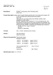
Example for dust on filter :<br />
1: PM-10-stage<br />
2: PM-2,5-stage<br />
3: Back-Up-filter
Table 1: Condition for the <strong>Impactor</strong><br />
<strong>Johnas</strong> II page 22<br />
Mittel min max<br />
Konzentration [mg/Nm³] 10 1 100<br />
Temperatur [°C] 135 20 250<br />
Druck [mbar] 1000 850 1100<br />
Feuchte [g/Nm³] 30 0 100<br />
Gaszusammensetzung Luft 30% CO2<br />
Kaminöffnung Standard 3"<br />
Table 2: Results Cut-Off of the University Duisburg:<br />
Geometric Aerodynamic<br />
cut off<br />
diameter<br />
diameter<br />
<strong>Johnas</strong> 2<br />
PM 10-Stage 10,00 µm 10,25 µm 51,8 ± 6,5 %<br />
PM 2,5-Stage 2,495 µm 2,56 µm 49,4 ± 2,1 %<br />
Table 3: Calibration Results of the University Duisburg of the effective Cut-Offs (d(ae)50):<br />
d(ae)50 deviation acceptance<br />
US-EPA<br />
PM 2,5-Stage 2,53 µm + 1,2 % ± 8 %<br />
PM 10-Stage 9,95 µm - 0,5 % ± 5 %
Figure 1: GMU - <strong>Impactor</strong> johnas<br />
<strong>Johnas</strong> II page 23
separation [%]<br />
100<br />
90<br />
80<br />
70<br />
60<br />
50<br />
40<br />
30<br />
20<br />
10<br />
<strong>Johnas</strong> II page 24<br />
0<br />
0.0 0.5 1.0 1.5 2.0 2.5 3.0 3.5 4.0 4.5 5.0 5.5 6.0 6.5 7.0 7.5 8.0 8.5 9.0 9.5 10.0 10.5<br />
d(ae) [µm]<br />
grease PM Filter PM US WINS<br />
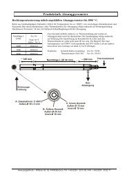
Figure 2: effective particulate matter of the stage 2.5 µm- GMU - <strong>Impactor</strong>s johnas, In the<br />
comparison with the US WINS PM 2.5-<strong>Impactor</strong> (calculated from "penetration efficiency<br />
curve")<br />
separation [%]<br />
100<br />
90<br />
80<br />
70<br />
60<br />
50<br />
40<br />
30<br />
20<br />
10<br />
0<br />
0.00 2.00 4.00 6.00 8.00 10.00 12.00 14.00 16.00 18.00 20.00<br />
d(ae) [µm]<br />
grease PM 10 Filter PM 10 thorax US PM 10-Inlet<br />
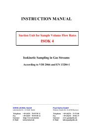
Figure 3: effective particulate matter of the stage 10 µm- GMU - <strong>Impactor</strong>s johnas, In the<br />
comparison with the US PM 10-Inlets (calculated from "effectiveness curve") and<br />
the thorax fraction
62,4<br />
Wall losses<br />
not consider<br />
37,6<br />
Figure 4: Mass of Al2O3- test dust on the impaction stages,<br />
<strong>Johnas</strong> II page 25<br />
Figure 5: Wall losses on the impact stages PM 10 and PM 2.5 in mass percent calculated to<br />
the total mass of each stage<br />
Picture 1: GMU - <strong>Impactor</strong>s johnas<br />
62,7<br />
10 µm - 2.5 < 2.5<br />
96,4 % 98,3 %<br />
3,6 %<br />
10 µm - 2.5 < 2.5<br />
Filter Wall losses<br />
1,7 %<br />
Wall losses<br />
consider<br />
37,3
Figure 6: Seals<br />
<strong>Johnas</strong> II page 26
Attention – In case of using the excel-file, this following license agreement will be accepted by the user!<br />
Achtung – Wird die Excel-Datei verwendet, akzeptiert der Benutzer diese folgende Lizenz-Vereinbarung!<br />
Excel-Berechnungsdatei für den Kaskadenimpaktor <strong>Johnas</strong><br />
Die auf dem Datenträger enthaltene Excel-Datei fällt unter den Schutz des Urheberrechtsgesetzes. Alle<br />
Urhebernutzungsrechte und andere geistigen Eigentumsrechte in Bezug auf die Datei verbleiben dem Programmautor<br />
und dem Lizenzgeber. Der Anwender erhält eine beschränkte, nicht ausschließliche und widerrufliche Lizenz zur<br />
Verwendung der Datei. Der Anwender verpflichtet sich, die Datei weder zu irgendwelchen Zwecken an andere<br />
Benutzer zu verleihen, zu vermieten, zu leasen oder zu unterlizensieren.<br />
Der Anwender verpflichtet sich, die Datei in angemessener Weise vor unbefugter Benutzung, Modifizierung,<br />
Vervielfältigung, Verteilung und Veröffentlichung zu schützen. Der Anwender erhält das Recht, zu Sicherheitszwecken<br />
eine Kopie der Datei anfertigen zu können. Für Verwendungen und Kopien der Datei zu anderen als in der Richtlinie<br />
angegebenen Belangen besteht keine Befugnis. Unverzüglich nach Erhalt des beiliegenden Datenträgers erfolgt eine<br />
Abnahmeprüfung durch den Anwender. Hierbei eventuell festgestellte Fehler wird der Lizenzgeber innerhalb von<br />
vierzehn Tagen beseitigen oder Ersatz liefern. Jede weitere Gewährleistung wird ausgeschlossen. Die hinter der<br />
Datei stehenden Modelle oder Modellvorstellungen stellen den Stand der Technik zur Zeit der Entwicklung der Datei<br />
dar. Für die Richtigkeit der Formeln, Modelle und/oder Programme wird keine Gewähr übernommen. Garantien<br />
bezüglich der Nutzung und Eignung der Datei für einen bestimmten Zweck werden nicht gegeben. In allen Fällen ist<br />
die Haftung auf den Datenträgerpreis begrenzt.<br />
Die auf dem Datenträger enthaltene Dateiversion kann jederzeit vom Lizenzgeber für ungültig erklärt werden. Wird<br />
die Richtlinie VDI 2066 Blatt 10 zurückgezogen oder durch eine Neuausgabe ersetzt, so verliert auch die<br />
dazugehörige Datei ihre Gültigkeit.<br />
<strong>Paul</strong> <strong>Gothe</strong>, Bochum den 10.12.03<br />
Excel-calculation-file for the Cascade impaktor <strong>Johnas</strong><br />
The Excel-file on the data disk falls under the protection of the copyright-law. All originator-usufructs and other mental<br />
titles in reference on the file remain by the program-author and the licensor. The user gets a limited, not exclusive and<br />
revocable license to the application of the file. The user commits himself neither to lend the file to any purposes to<br />
other users to rent to lease or to under-license.<br />
The user commits himself to protect the file in appropriate manner from unauthorised use, modification, duplication,<br />
distribution and publication. The user gets the right, to prepare a copy of the file for the security. Instantaneously after<br />
receipt of the enclosed data carrier, a decrease-examination takes place through the user. On this occasion possibly<br />
determined mistake will remove by the licensor within fourteen days or will deliver substitute. Each more guarantee is<br />
excluded. The models standing behind the calculation or model-ideas represent the stand of the technology at the<br />
time of the development of the file. For the correctness of the formulas, models and/or programs is taken on no<br />
assurance. Guarantees respecting the utilization and suitability of the file for a certain purpose are not given. In all<br />
cases, the liability is restricted on the data carrier-price.<br />
That on the data carrier existing file-version can be explained by the licensor for invalid at anytime. The guideline VDI<br />
2066 part 10 is withdrawn or is replaced with a reprint, so also the pertinent file loses their validity.<br />
<strong>Paul</strong> <strong>Gothe</strong>, Bochum the 2003-12-10,